media access layer
TRANSCRIPT
Medium Access(MAC) Sub-Layer
Multiple access ProtocolsTopologiesOverview of IEEE Standard 802 for LANS and MANSIntroduction to Wireless CommunicationIntroduction to Bridge Switch and Router
Elements of a wireless network
network
infrastructure
wireless hosts laptop smartphone
run applications
may be stationary (non-mobile) or mobile
wireless does notalways mean mobility
Elements of a wireless network
network
infrastructure
base station typically connected to
wired network
relay - responsible for sending packets between wired network and wireless host(s) in its ldquoareardquo
eg cell towers 80211 access points
Elements of a wireless network
network
infrastructure
wireless link typically used to
connect mobile(s) to base station
also used as backbone link
multiple access protocol coordinates link access
various data rates transmission distance
Elements of a wireless network
network
infrastructure
infrastructure mode base station connects
mobiles into wired network
handoff mobile changes base station providing connection into wired network
Elements of a wireless network
network
infrastructure
ad hoc mode
no base stations
nodes can only transmit to other nodes within link coverage
nodes organize themselves into a network route among themselves
Elements of a wireless network
Wireless Link Characteristics
important differences from wired link hellip
ndash decreased signal strength radio signal attenuates as it propagates through matter (path loss)
ndash interference from other sources standardized wireless network frequencies (eg 24 GHz) shared by other devices (eg phone) devices (motors) interfere as well
ndash multipath propagation radio signal reflects off objects ground arriving ad destination at slightly different times
hellip make communication across (even a point to point) wireless link much more ldquodifficultrdquo
Wireless Link Characteristics
bull SNR signal-to-noise ratio
ndash larger SNR ndash easier to extract signal from noise (a ldquogood thingrdquo)
bull SNR versus BER tradeoffsndash given physical layer increase power -gt increase SNR-gtdecrease
BER
Wireless network characteristics
Multiple wireless senders and receivers create additional problems (beyond multiple access)
AB
C
Hidden terminal problem
B A hear each other
B C hear each other
A C can not hear each other means A C unaware of their interference at B
A B C
Arsquos signal
strength
space
Crsquos signal
strength
Signal attenuation
B A hear each other
B C hear each other
A C can not hear each other interfering at B
IEEE 80211 Wireless LAN
80211b
bull 24-5 GHz unlicensed spectrum
bull up to 11 Mbps
80211n multiple antennae24-5 GHz rangeup to 200 Mbps
80211andash 5-6 GHz rangendash up to 54 Mbps
80211gndash 24-5 GHz rangendash up to 54 Mbps
all use CSMACA for multiple access
all have base-station and ad-hoc network versions
80211 LAN architecture
wireless host
communicates with base
station
base station = access
point (AP)
Basic Service Set (BSS)
(aka ldquocellrdquo) in
infrastructure mode
contains wireless hosts
access point (AP) base station
ad hoc mode hosts only
BSS 1
BSS 2
Internet
hub switch
or router
80211 Channels association
bull 80211b 24GHz-2485GHz spectrum divided into 11 channels at different frequencies
ndash AP admin chooses frequency for APndash interference possible channel can be same as that
chosen by neighboring AP
bull host must associate with an APndash scans channels listening for beacon frames containing
APrsquos name (SSID) and MAC addressndash selects AP to associate withndash may perform authenticationndash will typically run DHCP to get IP address in APrsquos
subnet
80211 passiveactive scanning
AP 2AP 1
H1
BSS 2BSS 1
1
23
1
passive scanning(1) beacon frames sent from APs
(2) association Request frame sent
H1 to selected AP
(3) association Response frame sent
from selected AP to H1
AP 2AP 1
H1
BSS 2BSS 1
122
34
active scanning (1) Probe Request frame broadcast
from H1
(2) Probe Response frames sent
from APs
(3) Association Request frame sent
H1 to selected AP
(4) Association Response frame sent
from selected AP to H1
IEEE 80211 multiple access
bull avoid collisions 2+ nodes transmitting at same time
bull 80211 CSMA - sense before transmitting
ndash donrsquot collide with ongoing transmission by other node
bull 80211 no collision detectionndash difficult to receive (sense collisions) when transmitting due to weak
received signals (fading)
ndash canrsquot sense all collisions in any case hidden terminal fading
ndash goal avoid collisions CSMAC(ollision)A(voidance)
space
AB
CA B C
Arsquos signal
strength
Crsquos signal
strength
IEEE 80211 MAC Protocol CSMACA
80211 sender
1 if sense channel idle for DIFS then
transmit entire frame (no CD)
2 if sense channel busy then
start random backoff time
timer counts down while channel idle
transmit when timer expires
if no ACK increase random backoff interval
repeat 2
80211 receiver
- if frame received OK
return ACK after SIFS (ACK needed due to
hidden terminal problem)
sender receiver
DIFS
data
SIFS
ACK
An Overview of Repeaters
bull Used for extending the physical span of a network
ndash An example is the extension of the distance between a hub and a node
bull Span is often limited by design considerations
bull 10base5
ndash The span is limited to 500 meters
A Repeater Connection
Expanding the Span of the Network
Source Black Box
Operations of a Repeater Within the ISO OSI Model
bull Operates at the lower level of the ISO OSI model
ndash Physical layer
Medium
Physical
LayerRepeater
Medium
Physical
Layer
An Overview of a Bridge
bull A device used for connecting two LANs operating under the same protocol
bull Currently the term bridge is loosely being used to describe different interconnecting devices
ndash Used now for connecting LANs operating under different protocols as well
Purpose of a Bridge
bull Facilitate the movement of data packet from one network segment to another
bull Not a sophisticated internetworking device
bull Bridge does not perform the routing of information to different segments of a network
bull Connects two network segments and not multiple network segments
Bridge
Bridge ISO-OSI Layer of Operation
X Medium X Medium
Physical
Layer
Physical
Layer
Data
Link
Layer
Data
Link
Layer
A simple bridge operates at the second layer of the ISO model
Practical Bridge Implementations
bull Local Bridge
bull Remote Bridge
Local and Remote Bridges
bull Local bridge
ndash Connects two different LANs located locally
bull Remote bridge
ndash Connects LAN segments that are geographically apart
ndash An example is a device that provide dial-up access to a LAN
Switch Definition and Purpose
bull A switch is defined as a device that allows a LAN to be segmented
ndash The segments will operate under the same protocol
Difference Between a Switch and a Bridge
bull A switch focuses on segmenting a LAN
bull A bridge is concerned with linking two network segments that operate under different protocols
Purpose of a Switch
bull Improve the network performance and reliability
bull Better manage the network in general
Switching Technologies
bull There are two major types of switching technologies
ndash Cut-through
ndash Store-and-forward
Cut-Through Technology
bull Reads only part of the packet
ndash The addresses header
ndash Packet is forwarded accordingly
bull Bad packets are not filtered
Store-and-Forward Technology
bull Entire packet is processed
bull Packets are filtered
ndash Bad packets are filtered
Switching Technology Comparison
Header Senderrsquos Add Receivers Add Data
Cut-through
Store-and-forward
Switching Technology Operation at the ISO Layer
bull In each of the two cases of switching technologies no protocol conversion takes place
bull Forwarding and filtering are done at the MAC layer
The Purpose of a Router
bull Connect LANs operating under different protocols
bull The LANs connected are better known as sub-networks instead of network segments
ndash The term segments is nevertheless used in practice
Router Characteristics
bull A router true internetworking device
ndash Connects different sub-networks together
bull Establishes a logical path of communication between the sub-networks
bull Contributes to the modular construction of a network
ndash Network itself is better managed
ndash Network resources are better utilized
Internetworking with a Router
IEEE 8023Sub-network IEEE 8025
Sub-network
PC-NFSSub-network
Router
Difference Between Routers Switches and Hubs
bull Hubsndash Simply provides the mechanical and electrical
connections between the nodes
bull Switchesndash Examine the data packet for the destination
addressndash Do not alter the data packets
bull Routersndash Examine and alter the data packetsndash Perform protocol conversion
Router Requirements
bull Requires more processing power compared to switches and bridges
bull Operations fall within the network layer of the ISO-OSI communication model
Router Network Layer Interface
X MEDIUM X MEDIUM
PHYSICAL
LAYER
PHYSICAL
LAYER
DATA LINK
LAYER
DATA LINK
LAYER
NETWORK
LAYERROUTER
NETWORK
LAYER
Devices and Layers
PHYSICAL
LAYER
DATA LINK
LAYER
NETWORK
LAYER
Switches
Routers
Repeaters
Swit
che
s
Layer 1
Layer 2
Layer 3
An Introduction to Gateways
bull Gateways are comprehensive internetworking devices
bull They can be computers themselves
Gateways in the Past
bull Very popular
bull They were the only devices that could be used for internetworking
bull Computers of the past were not designed with network connections in mind
ndash Interconnection of different computer systems has to be managed and driven by an advanced device such as a gateway
The Present Scenario
bull Computers are now designed with due consideration given to network connections
bull Larger networks could today be configured using internetworking devices
ndash Routers switches hubs etc
Gatewayrsquos Functional Relationship to the ISO-OSI Model
Application
Presentation
Session
Transport
Network
Data Link
Physical
Application
Presentation
Session
Transport
Network
Data Link
Physical
Link layer introduction
terminology hosts and routers nodes
communication channels that connect adjacent nodes along communication path links
wired links
wireless links
LANs
layer-2 packet frameencapsulates datagram
data-link layer has responsibility of transferring datagram from one node to physically adjacent node over a link
global ISP
Link layer context
datagram transferred by different link protocols over different links
eg Ethernet on first link frame relay on intermediate links 80211 on last link
each link protocol provides different services
eg may or may not provide rdt over link
transportation analogy trip from Princeton to Lausanne
limo Princeton to JFK
plane JFK to Geneva
train Geneva to Lausanne
tourist = datagram
transport segment = communication link
transportation mode = link layer protocol
travel agent = routing algorithm
Link layer services
bull framing link accessndash encapsulate datagram into frame adding
header trailerndash channel access if shared mediumndash ldquoMACrdquo addresses used in frame headers to
identify source dest bull different from IP address
bull reliable delivery between adjacent nodesndash seldom used on low bit-error link (fiber some
twisted pair)ndash wireless links high error rates
flow control pacing between adjacent sending and receiving nodes
error detection errors caused by signal attenuation noise
receiver detects presence of errors
bull signals sender for retransmission or drops frame
error correction receiver identifies and corrects bit error(s) without resorting to
retransmission
half-duplex and full-duplex with half duplex nodes at both ends of link can transmit but not
at same time
Link layer services (more)
Where is the link layer implemented
bull in each and every host
bull link layer implemented in ldquoadaptorrdquo (aka network interface card NIC) or on a chip
ndash Ethernet card 80211 card Ethernet chipset
ndash implements link physical layer
bull attaches into hostrsquos system buses
bull combination of hardware software firmware
controller
physical
transmission
cpu memory
host
bus
(eg PCI)
network adapter
card
application
transport
network
link
link
physical
Adaptors communicating
sending side
encapsulates datagram in frame
adds error checking bits rdt flow control etc
receiving side
looks for errors rdt flow control etc
extracts datagram passes to upper layer at receiving side
controller controller
sending host receiving host
datagram datagram
datagram
frame
Error detectionEDC= Error Detection and Correction bits (redundancy)
D = Data protected by error checking may include header fields
bull Error detection not 100 reliable
bull protocol may miss some errors but rarely
bull larger EDC field yields better detection and correction
otherwise
Parity checking
single bit parity detect single bit
errors
two-dimensional bit parity detect and correct single bit errors
0 0
Internet checksum (review)
senderbull treat segment contents
as sequence of 16-bit integers
bull checksum addition (1rsquos complement sum) of segment contents
bull sender puts checksum value into UDP checksum field
receiver compute checksum of
received segment check if computed
checksum equals checksum field value NO - error detected YES - no error detected
But maybe errors nonetheless
goal detect ldquoerrorsrdquo (eg flipped bits) in transmitted packet (note used at transport layer only)
Cyclic redundancy check
more powerful error-detection coding
view data bits D as a binary number
choose r+1 bit pattern (generator) G
goal choose r CRC bits R such that ltDRgt exactly divisible by G (modulo 2)
receiver knows G divides ltDRgt by G If non-zero remainder error detected
can detect all burst errors less than r+1 bits
widely used in practice (Ethernet 80211 WiFi ATM)
CRC example
wantD2r XOR R = nG
equivalentlyD2r = nG XOR R
equivalentlyif we divide D2r by G want remainder R to satisfy
R = remainder[ ]D2r
G
Multiple access links protocols
two types of ldquolinksrdquo
bull point-to-pointndash PPP for dial-up access
ndash point-to-point link between Ethernet switch host
bull broadcast (shared wire or medium)ndash old-fashioned Ethernet
ndash upstream HFC
ndash 80211 wireless LAN
shared wire (eg cabled Ethernet)
shared RF(eg 80211 WiFi)
shared RF(satellite)
humans at acocktail party
(shared air acoustical)
Multiple access protocols single shared broadcast channel
two or more simultaneous transmissions by nodes interference
collision if node receives two or more signals at the same time
multiple access protocol distributed algorithm that determines how nodes share
channel ie determine when node can transmit
communication about channel sharing must use channel itself no out-of-band channel for coordination
An ideal multiple access protocol
given broadcast channel of rate R bps
desiderata
1 when one node wants to transmit it can send at rate R
2 when M nodes want to transmit each can send at average rate RM
3 fully decentralized
bull no special node to coordinate transmissions
bull no synchronization of clocks slots
4 simple
MAC protocols taxonomy
three broad classes
bull channel partitioningndash divide channel into smaller ldquopiecesrdquo (time slots frequency code)
ndash allocate piece to node for exclusive use
bull random accessndash channel not divided allow collisions
ndash ldquorecoverrdquo from collisions
bull ldquotaking turnsrdquondash nodes take turns but nodes with more to send can take longer
turns
Channel partitioning MAC protocols TDMA
TDMA time division multiple accessaccess to channel in rounds each station gets fixed length slot (length =
pkt trans time) in each round unused slots go idle example 6-station LAN 134 have pkt
slots 256 idle
1 3 4 1 3 4
6-slot
frame
6-slot
frame
FDMA frequency division multiple access channel spectrum divided into frequency bands
each station assigned fixed frequency band
unused transmission time in frequency bands go idle
example 6-station LAN 134 have pkt frequency bands 256 idle
frequency b
ands
FDM cable
Channel partitioning MAC protocols FDMA
Random access protocols
bull when node has packet to sendndash transmit at full channel data rate Rndash no a priori coordination among nodes
bull two or more transmitting nodes ldquocollisionrdquo
bull random access MAC protocol specifies ndash how to detect collisionsndash how to recover from collisions (eg via
delayed retransmissions)
bull examples of random access MAC protocolsndash slotted ALOHAndash ALOHAndash CSMA CSMACD CSMACA
Slotted ALOHA
assumptions
all frames same size
time divided into equal size slots (time to transmit 1 frame)
nodes start to transmit only slot beginning
nodes are synchronized
if 2 or more nodes transmit in slot all nodes detect collision
operation when node obtains fresh
frame transmits in next slot
if no collision node can send new frame in next slot
if collision node retransmits frame in each subsequent slot with prob p until success
Pros
single active node can continuously transmit at full rate of channel
highly decentralized only slots in nodes need to be in sync
simple
Cons collisions wasting slots
idle slots
nodes may be able to detect collision in less than time to transmit packet
clock synchronization
Slotted ALOHA
1 1 1 1
2
3
2 2
3 3
node 1
node 2
node 3
C C CS S SE E E
suppose N nodes with many frames to send each transmits in slot with probability p
prob that given node has success in a slot = p(1-p)N-1
prob that any node has a success = Np(1-p)N-1
max efficiency find p that maximizes Np(1-p)N-1
for many nodes take limit of Np(1-p)N-1 as N goes to infinity gives
max efficiency = 1e = 37
efficiency long-run fraction of successful slots (many nodes all with many frames to send)
at best channelused for useful transmissions 37of time
Slotted ALOHA efficiency
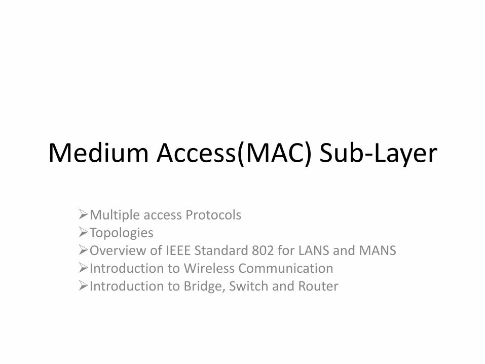
Pure (unslotted) ALOHA
unslotted Aloha simpler no synchronization
when frame first arrives
transmit immediately
collision probability increases
frame sent at t0 collides with other frames sent in [t0-1t0+1]
Pure ALOHA efficiency
P(success by given node) = P(node transmits)
P(no other node transmits in [t0-1t0]
P(no other node transmits in [t0-1t0]
= p (1-p)N-1 (1-p)N-1
= p (1-p)2(N-1)
hellip choosing optimum p and then letting n
= 1(2e) = 18
even worse than slotted Aloha
CSMA (carrier sense multiple access)
CSMA listen before transmitif channel sensed idle transmit entire frame
bull if channel sensed busy defer transmission
bull human analogy donrsquot interrupt others
CSMA collisions
bull collisions can still occur propagation delay means two nodes may not hear each otherrsquos transmission
bull collision entire packet transmission time wastedndash distance amp propagation
delay play role in in determining collision probability
spatial layout of nodes
CSMACD (collision detection)
CSMACD carrier sensing deferral as in CSMA
collisions detected within short time
colliding transmissions aborted reducing channel wastage
collision detection
easy in wired LANs measure signal strengths compare transmitted received signals
difficult in wireless LANs received signal strength overwhelmed by local transmission strength
human analogy the polite conversationalist
CSMACD (collision detection)
spatial layout of nodes
Ethernet CSMACD algorithm
1 NIC receives datagram from network layer creates frame
2 If NIC senses channel idle starts frame transmission If NIC senses channel busy waits until channel idle then transmits
3 If NIC transmits entire frame without detecting another transmission NIC is done with frame
4 If NIC detects another transmission while transmitting aborts and sends jam signal
5 After aborting NIC enters binary (exponential) backoff
ndash after mth collision NIC chooses K at random from 012 hellip 2m-1 NIC waits K512 bit times returns to Step 2
ndash longer backoff interval with more collisions
CSMACD efficiency
Tprop = max prop delay between 2 nodes in LAN
ttrans = time to transmit max-size frame
efficiency goes to 1
as tprop goes to 0
as ttrans goes to infinity
better performance than ALOHA and simple cheap
decentralized
transprop ttefficiency
51
1
ldquoTaking turnsrdquo MAC protocols
channel partitioning MAC protocols
ndash share channel efficiently and fairly at high load
ndash inefficient at low load delay in channel access 1N bandwidth allocated even if only 1 active node
random access MAC protocols
ndash efficient at low load single node can fully utilize channel
ndash high load collision overhead
ldquotaking turnsrdquo protocols
look for best of both worlds
pollingbull master node ldquoinvitesrdquo
slave nodes to transmit in turn
bull typically used with ldquodumbrdquo slave devices
bull concerns
ndash polling overhead
ndash latency
ndash single point of failure (master)
master
slaves
poll
data
data
ldquoTaking turnsrdquo MAC protocols
token passing control token passed
from one node to next sequentially
token message
concerns
token overhead
latency
single point of failure (token)
T
data
(nothing
to send)
T
ldquoTaking turnsrdquo MAC protocols
MAC addresses and ARP
bull 32-bit IP address
ndash network-layer address for interface
ndash used for layer 3 (network layer) forwarding
bull MAC (or LAN or physical or Ethernet) address
ndash function used lsquolocallyrdquo to get frame from one interface to another physically-connected interface (same network in IP-addressing sense)
ndash 48 bit MAC address (for most LANs) burned in NIC ROM also sometimes software settable
ndash eg 1A-2F-BB-76-09-AD
hexadecimal (base 16) notation
(each ldquonumberrdquo represents 4 bits)
LAN addresses and ARPeach adapter on LAN has unique LAN address
adapter
1A-2F-BB-76-09-AD
58-23-D7-FA-20-B0
0C-C4-11-6F-E3-98
71-65-F7-2B-08-53
LAN
(wired or
wireless)
LAN addresses (more)
MAC address allocation administered by IEEE
manufacturer buys portion of MAC address space (to assure uniqueness)
analogy
MAC address like Social Security Number
IP address like postal address
MAC flat address portability
can move LAN card from one LAN to another
IP hierarchical address not portable
address depends on IP subnet to which node is
ARP address resolution protocol
ARP table each IP node (host router) on LAN has table
IPMAC address mappings for some LAN nodes
lt IP address MAC address TTLgt
TTL (Time To Live) time after which address mapping will be forgotten (typically 20 min)
Question how to determine
interfacersquos MAC address
knowing its IP address
1A-2F-BB-76-09-AD
58-23-D7-FA-20-B0
0C-C4-11-6F-E3-98
71-65-F7-2B-08-53
LAN
137196723
137196778
137196714
137196788
ARP protocol same LAN
bull A wants to send datagram to B
ndash Brsquos MAC address not in Arsquos ARP table
bull A broadcasts ARP query packet containing Bs IP address ndash dest MAC address = FF-FF-
FF-FF-FF-FF
ndash all nodes on LAN receive ARP query
bull B receives ARP packet replies to A with its (Bs) MAC address
ndash frame sent to Arsquos MAC address (unicast)
bull A caches (saves) IP-to-MAC address pair in its ARP table until information becomes old (times out)ndash soft state information that
times out (goes away) unless refreshed
bull ARP is ldquoplug-and-playrdquondash nodes create their ARP
tables without intervention from net administrator
walkthrough send datagram from A to B via R
ndash focus on addressing ndash at IP (datagram) and MAC layer (frame)
ndash assume A knows Brsquos IP address
ndash assume A knows IP address of first hop router R (how)
ndash assume A knows Rrsquos MAC address (how)
Addressing routing to another LAN
R
1A-23-F9-CD-06-9B222222222220
111111111110E6-E9-00-17-BB-4BCC-49-DE-D0-AB-7D
111111111112
111111111111
74-29-9C-E8-FF-55
A
222222222222
49-BD-D2-C7-56-2A
22222222222188-B2-2F-54-1A-0F
B
R
1A-23-F9-CD-06-9B222222222220
111111111110E6-E9-00-17-BB-4BCC-49-DE-D0-AB-7D
111111111112
111111111111
74-29-9C-E8-FF-55
A
222222222222
49-BD-D2-C7-56-2A
22222222222188-B2-2F-54-1A-0F
B
Addressing routing to another LAN
IP
Eth
Phy
IP src 111111111111
IP dest 222222222222
A creates IP datagram with IP source A destination B
A creates link-layer frame with Rs MAC address as dest frame contains A-to-B IP datagram
MAC src 74-29-9C-E8-FF-55
MAC dest E6-E9-00-17-BB-4B
R
1A-23-F9-CD-06-9B222222222220
111111111110E6-E9-00-17-BB-4BCC-49-DE-D0-AB-7D
111111111112
111111111111
74-29-9C-E8-FF-55
A
222222222222
49-BD-D2-C7-56-2A
22222222222188-B2-2F-54-1A-0F
B
Addressing routing to another LAN
IP
Eth
Phy
frame sent from A to R
IP
Eth
Phy
frame received at R datagram removed passed up to IP
MAC src 74-29-9C-E8-FF-55
MAC dest E6-E9-00-17-BB-4B
IP src 111111111111
IP dest 222222222222
IP src 111111111111
IP dest 222222222222
R
1A-23-F9-CD-06-9B222222222220
111111111110E6-E9-00-17-BB-4BCC-49-DE-D0-AB-7D
111111111112
111111111111
74-29-9C-E8-FF-55
A
222222222222
49-BD-D2-C7-56-2A
22222222222188-B2-2F-54-1A-0F
B
Addressing routing to another LAN
IP src 111111111111
IP dest 222222222222
R forwards datagram with IP source A destination B
R creates link-layer frame with Bs MAC address as dest frame contains A-to-B IP datagram
MAC src 1A-23-F9-CD-06-9B
MAC dest 49-BD-D2-C7-56-2A
IP
Eth
Phy
IP
Eth
Phy
R
1A-23-F9-CD-06-9B222222222220
111111111110E6-E9-00-17-BB-4BCC-49-DE-D0-AB-7D
111111111112
111111111111
74-29-9C-E8-FF-55
A
222222222222
49-BD-D2-C7-56-2A
22222222222188-B2-2F-54-1A-0F
B
Addressing routing to another LAN R forwards datagram with IP source A destination B
R creates link-layer frame with Bs MAC address as dest frame contains A-to-B IP datagram
IP src 111111111111
IP dest 222222222222
MAC src 1A-23-F9-CD-06-9B
MAC dest 49-BD-D2-C7-56-2A
IP
Eth
Phy
Ethernet
ldquodominantrdquo wired LAN technology
bull cheap $20 for NIC
bull first widely used LAN technology
bull simpler cheaper than token LANs and ATM
bull kept up with speed race 10 Mbps ndash 10 Gbps
Metcalfersquos Ethernet sketch
Ethernet physical topology
bull bus popular through mid 90sndash all nodes in same collision domain (can collide with
each other)
bull star prevails todayndash active switch in center
ndash each ldquospokerdquo runs a (separate) Ethernet protocol (nodes do not collide with each other)
switch
bus coaxial cablestar
Ethernet frame structure
sending adapter encapsulates IP datagram (or other network layer protocol packet) in Ethernet frame
preamble
7 bytes with pattern 10101010 followed by one byte with pattern 10101011
used to synchronize receiver sender clock rates
destaddress
sourceaddress
data (payload) CRCpreamble
type
Ethernet frame structure (more)
addresses 6 byte source destination MAC addresses
if adapter receives frame with matching destination address or with broadcast address (eg ARP packet) it passes data in frame to network layer protocol
otherwise adapter discards frame
type indicates higher layer protocol (mostly IP but others possible eg Novell IPX AppleTalk)
CRC cyclic redundancy check at receiver
error detected frame is dropped
destaddress
sourceaddress
data (payload) CRCpreamble
type
Ethernet unreliable connectionless
bull connectionless no handshaking between sending and receiving NICs
bull unreliable receiving NIC doesnt send acks or nacks to sending NIC
ndash data in dropped frames recovered only if initial sender uses higher layer rdt (eg TCP) otherwise dropped data lost
Switch multiple simultaneous transmissions
bull hosts have dedicated direct connection to switch
bull switches buffer packets
bull Ethernet protocol used on eachincoming link but no collisions full duplex
ndash each link is its own collision domain
bull switching A-to-Arsquo and B-to-Brsquocan transmit simultaneously without collisions switch with six interfaces
(123456)
A
Arsquo
B
Brsquo C
Crsquo
1 2
345
6
Switch forwarding table
Q how does switch know Arsquo reachable via interface 4 Brsquo reachable via interface 5
switch with six interfaces
(123456)
A
Arsquo
B
Brsquo C
Crsquo
1 2
345
6 A each switch has a switch table each entry
(MAC address of host
interface to reach host time
stamp)
looks like a routing table
Q how are entries created maintained in switch table
something like a routing protocol
A
Arsquo
B
Brsquo C
Crsquo
1 2
345
6
Switch self-learning
bull switch learns which hosts can be reached through which interfaces
ndash when frame received switch ldquolearnsrdquo location of sender incoming LAN segment
ndash records senderlocation pair in switch table
A Arsquo
Source A
Dest Arsquo
MAC addr interface TTL
Switch table
(initially empty)A 1 60
A
Arsquo
B
Brsquo C
Crsquo
1 2
345
6
Self-learning forwarding example
A Arsquo
Source A
Dest Arsquo
MAC addr interface TTL
switch table
(initially empty)A 1 60
A ArsquoA ArsquoA ArsquoA ArsquoA Arsquo
bull frame destination Arsquo locaton unknownflood
Arsquo A
destination A location
known
Arsquo 4 60
selectively send
on just one link
Interconnecting switches
switches can be connected together
Q sending from A to G - how does S1 know to forward frame destined to F via S4 and S3
A self learning (works exactly the same as in single-switch case)
A
B
S1
C D
E
F
S2
S4
S3
H
I
G
Self-learning multi-switch example
Suppose C sends frame to I I responds to C
Q show switch tables and packet forwarding in S1 S2 S3 S4
A
B
S1
C D
E
F
S2
S4
S3
H
I
G
Switches vs routers
both are store-and-forward
routers network-layer devices (examine network-layer headers)
switches link-layer devices (examine link-layer headers)
both have forwarding tables routers compute tables
using routing algorithms IP addresses
switches learn forwarding table using flooding learning MAC addresses
application
transport
network
link
physical
network
link
physical
link
physical
switch
datagram
application
transport
network
link
physical
frame
frame
frame
datagram
VLANs motivation
consider CS user moves office to EE
but wants connect to CS switch
single broadcast domain
all layer-2 broadcast traffic (ARP DHCP unknown location of destination MAC address) must cross entire LAN
securityprivacy efficiency issues
Computer
Science Electrical
Engineering
Computer
Engineering
VLANsport-based VLAN switch ports
grouped (by switch management software) so that single physical switch helliphellip
switch(es) supporting
VLAN capabilities can
be configured to
define multiple virtual
LANS over single
physical LAN
infrastructure
Virtual Local
Area Network1
8
9
16102
7
hellip
Electrical Engineering
(VLAN ports 1-8)
Computer Science
(VLAN ports 9-15)
15
hellip
Electrical Engineering
(VLAN ports 1-8)
hellip
1
82
7 9
1610
15
hellip
Computer Science
(VLAN ports 9-16)
hellip operates as multiple virtual switches
Port-based VLAN
1
8
9
16102
7
hellip
Electrical Engineering
(VLAN ports 1-8)
Computer Science
(VLAN ports 9-15)
15
hellip
traffic isolation frames tofrom ports 1-8 can onlyreach ports 1-8 can also define VLAN based on
MAC addresses of endpoints rather than switch port
dynamic membershipports can be dynamically assigned among VLANs
router
forwarding between VLANSdone via routing (just as with separate switches) in practice vendors sell combined
switches plus routers

Elements of a wireless network
network
infrastructure
wireless hosts laptop smartphone
run applications
may be stationary (non-mobile) or mobile
wireless does notalways mean mobility
Elements of a wireless network
network
infrastructure
base station typically connected to
wired network
relay - responsible for sending packets between wired network and wireless host(s) in its ldquoareardquo
eg cell towers 80211 access points
Elements of a wireless network
network
infrastructure
wireless link typically used to
connect mobile(s) to base station
also used as backbone link
multiple access protocol coordinates link access
various data rates transmission distance
Elements of a wireless network
network
infrastructure
infrastructure mode base station connects
mobiles into wired network
handoff mobile changes base station providing connection into wired network
Elements of a wireless network
network
infrastructure
ad hoc mode
no base stations
nodes can only transmit to other nodes within link coverage
nodes organize themselves into a network route among themselves
Elements of a wireless network
Wireless Link Characteristics
important differences from wired link hellip
ndash decreased signal strength radio signal attenuates as it propagates through matter (path loss)
ndash interference from other sources standardized wireless network frequencies (eg 24 GHz) shared by other devices (eg phone) devices (motors) interfere as well
ndash multipath propagation radio signal reflects off objects ground arriving ad destination at slightly different times
hellip make communication across (even a point to point) wireless link much more ldquodifficultrdquo
Wireless Link Characteristics
bull SNR signal-to-noise ratio
ndash larger SNR ndash easier to extract signal from noise (a ldquogood thingrdquo)
bull SNR versus BER tradeoffsndash given physical layer increase power -gt increase SNR-gtdecrease
BER
Wireless network characteristics
Multiple wireless senders and receivers create additional problems (beyond multiple access)
AB
C
Hidden terminal problem
B A hear each other
B C hear each other
A C can not hear each other means A C unaware of their interference at B
A B C
Arsquos signal
strength
space
Crsquos signal
strength
Signal attenuation
B A hear each other
B C hear each other
A C can not hear each other interfering at B
IEEE 80211 Wireless LAN
80211b
bull 24-5 GHz unlicensed spectrum
bull up to 11 Mbps
80211n multiple antennae24-5 GHz rangeup to 200 Mbps
80211andash 5-6 GHz rangendash up to 54 Mbps
80211gndash 24-5 GHz rangendash up to 54 Mbps
all use CSMACA for multiple access
all have base-station and ad-hoc network versions
80211 LAN architecture
wireless host
communicates with base
station
base station = access
point (AP)
Basic Service Set (BSS)
(aka ldquocellrdquo) in
infrastructure mode
contains wireless hosts
access point (AP) base station
ad hoc mode hosts only
BSS 1
BSS 2
Internet
hub switch
or router
80211 Channels association
bull 80211b 24GHz-2485GHz spectrum divided into 11 channels at different frequencies
ndash AP admin chooses frequency for APndash interference possible channel can be same as that
chosen by neighboring AP
bull host must associate with an APndash scans channels listening for beacon frames containing
APrsquos name (SSID) and MAC addressndash selects AP to associate withndash may perform authenticationndash will typically run DHCP to get IP address in APrsquos
subnet
80211 passiveactive scanning
AP 2AP 1
H1
BSS 2BSS 1
1
23
1
passive scanning(1) beacon frames sent from APs
(2) association Request frame sent
H1 to selected AP
(3) association Response frame sent
from selected AP to H1
AP 2AP 1
H1
BSS 2BSS 1
122
34
active scanning (1) Probe Request frame broadcast
from H1
(2) Probe Response frames sent
from APs
(3) Association Request frame sent
H1 to selected AP
(4) Association Response frame sent
from selected AP to H1
IEEE 80211 multiple access
bull avoid collisions 2+ nodes transmitting at same time
bull 80211 CSMA - sense before transmitting
ndash donrsquot collide with ongoing transmission by other node
bull 80211 no collision detectionndash difficult to receive (sense collisions) when transmitting due to weak
received signals (fading)
ndash canrsquot sense all collisions in any case hidden terminal fading
ndash goal avoid collisions CSMAC(ollision)A(voidance)
space
AB
CA B C
Arsquos signal
strength
Crsquos signal
strength
IEEE 80211 MAC Protocol CSMACA
80211 sender
1 if sense channel idle for DIFS then
transmit entire frame (no CD)
2 if sense channel busy then
start random backoff time
timer counts down while channel idle
transmit when timer expires
if no ACK increase random backoff interval
repeat 2
80211 receiver
- if frame received OK
return ACK after SIFS (ACK needed due to
hidden terminal problem)
sender receiver
DIFS
data
SIFS
ACK
An Overview of Repeaters
bull Used for extending the physical span of a network
ndash An example is the extension of the distance between a hub and a node
bull Span is often limited by design considerations
bull 10base5
ndash The span is limited to 500 meters
A Repeater Connection
Expanding the Span of the Network
Source Black Box
Operations of a Repeater Within the ISO OSI Model
bull Operates at the lower level of the ISO OSI model
ndash Physical layer
Medium
Physical
LayerRepeater
Medium
Physical
Layer
An Overview of a Bridge
bull A device used for connecting two LANs operating under the same protocol
bull Currently the term bridge is loosely being used to describe different interconnecting devices
ndash Used now for connecting LANs operating under different protocols as well
Purpose of a Bridge
bull Facilitate the movement of data packet from one network segment to another
bull Not a sophisticated internetworking device
bull Bridge does not perform the routing of information to different segments of a network
bull Connects two network segments and not multiple network segments
Bridge
Bridge ISO-OSI Layer of Operation
X Medium X Medium
Physical
Layer
Physical
Layer
Data
Link
Layer
Data
Link
Layer
A simple bridge operates at the second layer of the ISO model
Practical Bridge Implementations
bull Local Bridge
bull Remote Bridge
Local and Remote Bridges
bull Local bridge
ndash Connects two different LANs located locally
bull Remote bridge
ndash Connects LAN segments that are geographically apart
ndash An example is a device that provide dial-up access to a LAN
Switch Definition and Purpose
bull A switch is defined as a device that allows a LAN to be segmented
ndash The segments will operate under the same protocol
Difference Between a Switch and a Bridge
bull A switch focuses on segmenting a LAN
bull A bridge is concerned with linking two network segments that operate under different protocols
Purpose of a Switch
bull Improve the network performance and reliability
bull Better manage the network in general
Switching Technologies
bull There are two major types of switching technologies
ndash Cut-through
ndash Store-and-forward
Cut-Through Technology
bull Reads only part of the packet
ndash The addresses header
ndash Packet is forwarded accordingly
bull Bad packets are not filtered
Store-and-Forward Technology
bull Entire packet is processed
bull Packets are filtered
ndash Bad packets are filtered
Switching Technology Comparison
Header Senderrsquos Add Receivers Add Data
Cut-through
Store-and-forward
Switching Technology Operation at the ISO Layer
bull In each of the two cases of switching technologies no protocol conversion takes place
bull Forwarding and filtering are done at the MAC layer
The Purpose of a Router
bull Connect LANs operating under different protocols
bull The LANs connected are better known as sub-networks instead of network segments
ndash The term segments is nevertheless used in practice
Router Characteristics
bull A router true internetworking device
ndash Connects different sub-networks together
bull Establishes a logical path of communication between the sub-networks
bull Contributes to the modular construction of a network
ndash Network itself is better managed
ndash Network resources are better utilized
Internetworking with a Router
IEEE 8023Sub-network IEEE 8025
Sub-network
PC-NFSSub-network
Router
Difference Between Routers Switches and Hubs
bull Hubsndash Simply provides the mechanical and electrical
connections between the nodes
bull Switchesndash Examine the data packet for the destination
addressndash Do not alter the data packets
bull Routersndash Examine and alter the data packetsndash Perform protocol conversion
Router Requirements
bull Requires more processing power compared to switches and bridges
bull Operations fall within the network layer of the ISO-OSI communication model
Router Network Layer Interface
X MEDIUM X MEDIUM
PHYSICAL
LAYER
PHYSICAL
LAYER
DATA LINK
LAYER
DATA LINK
LAYER
NETWORK
LAYERROUTER
NETWORK
LAYER
Devices and Layers
PHYSICAL
LAYER
DATA LINK
LAYER
NETWORK
LAYER
Switches
Routers
Repeaters
Swit
che
s
Layer 1
Layer 2
Layer 3
An Introduction to Gateways
bull Gateways are comprehensive internetworking devices
bull They can be computers themselves
Gateways in the Past
bull Very popular
bull They were the only devices that could be used for internetworking
bull Computers of the past were not designed with network connections in mind
ndash Interconnection of different computer systems has to be managed and driven by an advanced device such as a gateway
The Present Scenario
bull Computers are now designed with due consideration given to network connections
bull Larger networks could today be configured using internetworking devices
ndash Routers switches hubs etc
Gatewayrsquos Functional Relationship to the ISO-OSI Model
Application
Presentation
Session
Transport
Network
Data Link
Physical
Application
Presentation
Session
Transport
Network
Data Link
Physical
Link layer introduction
terminology hosts and routers nodes
communication channels that connect adjacent nodes along communication path links
wired links
wireless links
LANs
layer-2 packet frameencapsulates datagram
data-link layer has responsibility of transferring datagram from one node to physically adjacent node over a link
global ISP
Link layer context
datagram transferred by different link protocols over different links
eg Ethernet on first link frame relay on intermediate links 80211 on last link
each link protocol provides different services
eg may or may not provide rdt over link
transportation analogy trip from Princeton to Lausanne
limo Princeton to JFK
plane JFK to Geneva
train Geneva to Lausanne
tourist = datagram
transport segment = communication link
transportation mode = link layer protocol
travel agent = routing algorithm
Link layer services
bull framing link accessndash encapsulate datagram into frame adding
header trailerndash channel access if shared mediumndash ldquoMACrdquo addresses used in frame headers to
identify source dest bull different from IP address
bull reliable delivery between adjacent nodesndash seldom used on low bit-error link (fiber some
twisted pair)ndash wireless links high error rates
flow control pacing between adjacent sending and receiving nodes
error detection errors caused by signal attenuation noise
receiver detects presence of errors
bull signals sender for retransmission or drops frame
error correction receiver identifies and corrects bit error(s) without resorting to
retransmission
half-duplex and full-duplex with half duplex nodes at both ends of link can transmit but not
at same time
Link layer services (more)
Where is the link layer implemented
bull in each and every host
bull link layer implemented in ldquoadaptorrdquo (aka network interface card NIC) or on a chip
ndash Ethernet card 80211 card Ethernet chipset
ndash implements link physical layer
bull attaches into hostrsquos system buses
bull combination of hardware software firmware
controller
physical
transmission
cpu memory
host
bus
(eg PCI)
network adapter
card
application
transport
network
link
link
physical
Adaptors communicating
sending side
encapsulates datagram in frame
adds error checking bits rdt flow control etc
receiving side
looks for errors rdt flow control etc
extracts datagram passes to upper layer at receiving side
controller controller
sending host receiving host
datagram datagram
datagram
frame
Error detectionEDC= Error Detection and Correction bits (redundancy)
D = Data protected by error checking may include header fields
bull Error detection not 100 reliable
bull protocol may miss some errors but rarely
bull larger EDC field yields better detection and correction
otherwise
Parity checking
single bit parity detect single bit
errors
two-dimensional bit parity detect and correct single bit errors
0 0
Internet checksum (review)
senderbull treat segment contents
as sequence of 16-bit integers
bull checksum addition (1rsquos complement sum) of segment contents
bull sender puts checksum value into UDP checksum field
receiver compute checksum of
received segment check if computed
checksum equals checksum field value NO - error detected YES - no error detected
But maybe errors nonetheless
goal detect ldquoerrorsrdquo (eg flipped bits) in transmitted packet (note used at transport layer only)
Cyclic redundancy check
more powerful error-detection coding
view data bits D as a binary number
choose r+1 bit pattern (generator) G
goal choose r CRC bits R such that ltDRgt exactly divisible by G (modulo 2)
receiver knows G divides ltDRgt by G If non-zero remainder error detected
can detect all burst errors less than r+1 bits
widely used in practice (Ethernet 80211 WiFi ATM)
CRC example
wantD2r XOR R = nG
equivalentlyD2r = nG XOR R
equivalentlyif we divide D2r by G want remainder R to satisfy
R = remainder[ ]D2r
G
Multiple access links protocols
two types of ldquolinksrdquo
bull point-to-pointndash PPP for dial-up access
ndash point-to-point link between Ethernet switch host
bull broadcast (shared wire or medium)ndash old-fashioned Ethernet
ndash upstream HFC
ndash 80211 wireless LAN
shared wire (eg cabled Ethernet)
shared RF(eg 80211 WiFi)
shared RF(satellite)
humans at acocktail party
(shared air acoustical)
Multiple access protocols single shared broadcast channel
two or more simultaneous transmissions by nodes interference
collision if node receives two or more signals at the same time
multiple access protocol distributed algorithm that determines how nodes share
channel ie determine when node can transmit
communication about channel sharing must use channel itself no out-of-band channel for coordination
An ideal multiple access protocol
given broadcast channel of rate R bps
desiderata
1 when one node wants to transmit it can send at rate R
2 when M nodes want to transmit each can send at average rate RM
3 fully decentralized
bull no special node to coordinate transmissions
bull no synchronization of clocks slots
4 simple
MAC protocols taxonomy
three broad classes
bull channel partitioningndash divide channel into smaller ldquopiecesrdquo (time slots frequency code)
ndash allocate piece to node for exclusive use
bull random accessndash channel not divided allow collisions
ndash ldquorecoverrdquo from collisions
bull ldquotaking turnsrdquondash nodes take turns but nodes with more to send can take longer
turns
Channel partitioning MAC protocols TDMA
TDMA time division multiple accessaccess to channel in rounds each station gets fixed length slot (length =
pkt trans time) in each round unused slots go idle example 6-station LAN 134 have pkt
slots 256 idle
1 3 4 1 3 4
6-slot
frame
6-slot
frame
FDMA frequency division multiple access channel spectrum divided into frequency bands
each station assigned fixed frequency band
unused transmission time in frequency bands go idle
example 6-station LAN 134 have pkt frequency bands 256 idle
frequency b
ands
FDM cable
Channel partitioning MAC protocols FDMA
Random access protocols
bull when node has packet to sendndash transmit at full channel data rate Rndash no a priori coordination among nodes
bull two or more transmitting nodes ldquocollisionrdquo
bull random access MAC protocol specifies ndash how to detect collisionsndash how to recover from collisions (eg via
delayed retransmissions)
bull examples of random access MAC protocolsndash slotted ALOHAndash ALOHAndash CSMA CSMACD CSMACA
Slotted ALOHA
assumptions
all frames same size
time divided into equal size slots (time to transmit 1 frame)
nodes start to transmit only slot beginning
nodes are synchronized
if 2 or more nodes transmit in slot all nodes detect collision
operation when node obtains fresh
frame transmits in next slot
if no collision node can send new frame in next slot
if collision node retransmits frame in each subsequent slot with prob p until success
Pros
single active node can continuously transmit at full rate of channel
highly decentralized only slots in nodes need to be in sync
simple
Cons collisions wasting slots
idle slots
nodes may be able to detect collision in less than time to transmit packet
clock synchronization
Slotted ALOHA
1 1 1 1
2
3
2 2
3 3
node 1
node 2
node 3
C C CS S SE E E
suppose N nodes with many frames to send each transmits in slot with probability p
prob that given node has success in a slot = p(1-p)N-1
prob that any node has a success = Np(1-p)N-1
max efficiency find p that maximizes Np(1-p)N-1
for many nodes take limit of Np(1-p)N-1 as N goes to infinity gives
max efficiency = 1e = 37
efficiency long-run fraction of successful slots (many nodes all with many frames to send)
at best channelused for useful transmissions 37of time
Slotted ALOHA efficiency
Pure (unslotted) ALOHA
unslotted Aloha simpler no synchronization
when frame first arrives
transmit immediately
collision probability increases
frame sent at t0 collides with other frames sent in [t0-1t0+1]
Pure ALOHA efficiency
P(success by given node) = P(node transmits)
P(no other node transmits in [t0-1t0]
P(no other node transmits in [t0-1t0]
= p (1-p)N-1 (1-p)N-1
= p (1-p)2(N-1)
hellip choosing optimum p and then letting n
= 1(2e) = 18
even worse than slotted Aloha
CSMA (carrier sense multiple access)
CSMA listen before transmitif channel sensed idle transmit entire frame
bull if channel sensed busy defer transmission
bull human analogy donrsquot interrupt others
CSMA collisions
bull collisions can still occur propagation delay means two nodes may not hear each otherrsquos transmission
bull collision entire packet transmission time wastedndash distance amp propagation
delay play role in in determining collision probability
spatial layout of nodes
CSMACD (collision detection)
CSMACD carrier sensing deferral as in CSMA
collisions detected within short time
colliding transmissions aborted reducing channel wastage
collision detection
easy in wired LANs measure signal strengths compare transmitted received signals
difficult in wireless LANs received signal strength overwhelmed by local transmission strength
human analogy the polite conversationalist
CSMACD (collision detection)
spatial layout of nodes
Ethernet CSMACD algorithm
1 NIC receives datagram from network layer creates frame
2 If NIC senses channel idle starts frame transmission If NIC senses channel busy waits until channel idle then transmits
3 If NIC transmits entire frame without detecting another transmission NIC is done with frame
4 If NIC detects another transmission while transmitting aborts and sends jam signal
5 After aborting NIC enters binary (exponential) backoff
ndash after mth collision NIC chooses K at random from 012 hellip 2m-1 NIC waits K512 bit times returns to Step 2
ndash longer backoff interval with more collisions
CSMACD efficiency
Tprop = max prop delay between 2 nodes in LAN
ttrans = time to transmit max-size frame
efficiency goes to 1
as tprop goes to 0
as ttrans goes to infinity
better performance than ALOHA and simple cheap
decentralized
transprop ttefficiency
51
1
ldquoTaking turnsrdquo MAC protocols
channel partitioning MAC protocols
ndash share channel efficiently and fairly at high load
ndash inefficient at low load delay in channel access 1N bandwidth allocated even if only 1 active node
random access MAC protocols
ndash efficient at low load single node can fully utilize channel
ndash high load collision overhead
ldquotaking turnsrdquo protocols
look for best of both worlds
pollingbull master node ldquoinvitesrdquo
slave nodes to transmit in turn
bull typically used with ldquodumbrdquo slave devices
bull concerns
ndash polling overhead
ndash latency
ndash single point of failure (master)
master
slaves
poll
data
data
ldquoTaking turnsrdquo MAC protocols
token passing control token passed
from one node to next sequentially
token message
concerns
token overhead
latency
single point of failure (token)
T
data
(nothing
to send)
T
ldquoTaking turnsrdquo MAC protocols
MAC addresses and ARP
bull 32-bit IP address
ndash network-layer address for interface
ndash used for layer 3 (network layer) forwarding
bull MAC (or LAN or physical or Ethernet) address
ndash function used lsquolocallyrdquo to get frame from one interface to another physically-connected interface (same network in IP-addressing sense)
ndash 48 bit MAC address (for most LANs) burned in NIC ROM also sometimes software settable
ndash eg 1A-2F-BB-76-09-AD
hexadecimal (base 16) notation
(each ldquonumberrdquo represents 4 bits)
LAN addresses and ARPeach adapter on LAN has unique LAN address
adapter
1A-2F-BB-76-09-AD
58-23-D7-FA-20-B0
0C-C4-11-6F-E3-98
71-65-F7-2B-08-53
LAN
(wired or
wireless)
LAN addresses (more)
MAC address allocation administered by IEEE
manufacturer buys portion of MAC address space (to assure uniqueness)
analogy
MAC address like Social Security Number
IP address like postal address
MAC flat address portability
can move LAN card from one LAN to another
IP hierarchical address not portable
address depends on IP subnet to which node is
ARP address resolution protocol
ARP table each IP node (host router) on LAN has table
IPMAC address mappings for some LAN nodes
lt IP address MAC address TTLgt
TTL (Time To Live) time after which address mapping will be forgotten (typically 20 min)
Question how to determine
interfacersquos MAC address
knowing its IP address
1A-2F-BB-76-09-AD
58-23-D7-FA-20-B0
0C-C4-11-6F-E3-98
71-65-F7-2B-08-53
LAN
137196723
137196778
137196714
137196788
ARP protocol same LAN
bull A wants to send datagram to B
ndash Brsquos MAC address not in Arsquos ARP table
bull A broadcasts ARP query packet containing Bs IP address ndash dest MAC address = FF-FF-
FF-FF-FF-FF
ndash all nodes on LAN receive ARP query
bull B receives ARP packet replies to A with its (Bs) MAC address
ndash frame sent to Arsquos MAC address (unicast)
bull A caches (saves) IP-to-MAC address pair in its ARP table until information becomes old (times out)ndash soft state information that
times out (goes away) unless refreshed
bull ARP is ldquoplug-and-playrdquondash nodes create their ARP
tables without intervention from net administrator
walkthrough send datagram from A to B via R
ndash focus on addressing ndash at IP (datagram) and MAC layer (frame)
ndash assume A knows Brsquos IP address
ndash assume A knows IP address of first hop router R (how)
ndash assume A knows Rrsquos MAC address (how)
Addressing routing to another LAN
R
1A-23-F9-CD-06-9B222222222220
111111111110E6-E9-00-17-BB-4BCC-49-DE-D0-AB-7D
111111111112
111111111111
74-29-9C-E8-FF-55
A
222222222222
49-BD-D2-C7-56-2A
22222222222188-B2-2F-54-1A-0F
B
R
1A-23-F9-CD-06-9B222222222220
111111111110E6-E9-00-17-BB-4BCC-49-DE-D0-AB-7D
111111111112
111111111111
74-29-9C-E8-FF-55
A
222222222222
49-BD-D2-C7-56-2A
22222222222188-B2-2F-54-1A-0F
B
Addressing routing to another LAN
IP
Eth
Phy
IP src 111111111111
IP dest 222222222222
A creates IP datagram with IP source A destination B
A creates link-layer frame with Rs MAC address as dest frame contains A-to-B IP datagram
MAC src 74-29-9C-E8-FF-55
MAC dest E6-E9-00-17-BB-4B
R
1A-23-F9-CD-06-9B222222222220
111111111110E6-E9-00-17-BB-4BCC-49-DE-D0-AB-7D
111111111112
111111111111
74-29-9C-E8-FF-55
A
222222222222
49-BD-D2-C7-56-2A
22222222222188-B2-2F-54-1A-0F
B
Addressing routing to another LAN
IP
Eth
Phy
frame sent from A to R
IP
Eth
Phy
frame received at R datagram removed passed up to IP
MAC src 74-29-9C-E8-FF-55
MAC dest E6-E9-00-17-BB-4B
IP src 111111111111
IP dest 222222222222
IP src 111111111111
IP dest 222222222222
R
1A-23-F9-CD-06-9B222222222220
111111111110E6-E9-00-17-BB-4BCC-49-DE-D0-AB-7D
111111111112
111111111111
74-29-9C-E8-FF-55
A
222222222222
49-BD-D2-C7-56-2A
22222222222188-B2-2F-54-1A-0F
B
Addressing routing to another LAN
IP src 111111111111
IP dest 222222222222
R forwards datagram with IP source A destination B
R creates link-layer frame with Bs MAC address as dest frame contains A-to-B IP datagram
MAC src 1A-23-F9-CD-06-9B
MAC dest 49-BD-D2-C7-56-2A
IP
Eth
Phy
IP
Eth
Phy
R
1A-23-F9-CD-06-9B222222222220
111111111110E6-E9-00-17-BB-4BCC-49-DE-D0-AB-7D
111111111112
111111111111
74-29-9C-E8-FF-55
A
222222222222
49-BD-D2-C7-56-2A
22222222222188-B2-2F-54-1A-0F
B
Addressing routing to another LAN R forwards datagram with IP source A destination B
R creates link-layer frame with Bs MAC address as dest frame contains A-to-B IP datagram
IP src 111111111111
IP dest 222222222222
MAC src 1A-23-F9-CD-06-9B
MAC dest 49-BD-D2-C7-56-2A
IP
Eth
Phy
IP
Eth
Phy
R
1A-23-F9-CD-06-9B222222222220
111111111110E6-E9-00-17-BB-4BCC-49-DE-D0-AB-7D
111111111112
111111111111
74-29-9C-E8-FF-55
A
222222222222
49-BD-D2-C7-56-2A
22222222222188-B2-2F-54-1A-0F
B
Addressing routing to another LAN R forwards datagram with IP source A destination B
R creates link-layer frame with Bs MAC address as dest frame contains A-to-B IP datagram
IP src 111111111111
IP dest 222222222222
MAC src 1A-23-F9-CD-06-9B
MAC dest 49-BD-D2-C7-56-2A
IP
Eth
Phy
Ethernet
ldquodominantrdquo wired LAN technology
bull cheap $20 for NIC
bull first widely used LAN technology
bull simpler cheaper than token LANs and ATM
bull kept up with speed race 10 Mbps ndash 10 Gbps
Metcalfersquos Ethernet sketch
Ethernet physical topology
bull bus popular through mid 90sndash all nodes in same collision domain (can collide with
each other)
bull star prevails todayndash active switch in center
ndash each ldquospokerdquo runs a (separate) Ethernet protocol (nodes do not collide with each other)
switch
bus coaxial cablestar
Ethernet frame structure
sending adapter encapsulates IP datagram (or other network layer protocol packet) in Ethernet frame
preamble
7 bytes with pattern 10101010 followed by one byte with pattern 10101011
used to synchronize receiver sender clock rates
destaddress
sourceaddress
data (payload) CRCpreamble
type
Ethernet frame structure (more)
addresses 6 byte source destination MAC addresses
if adapter receives frame with matching destination address or with broadcast address (eg ARP packet) it passes data in frame to network layer protocol
otherwise adapter discards frame
type indicates higher layer protocol (mostly IP but others possible eg Novell IPX AppleTalk)
CRC cyclic redundancy check at receiver
error detected frame is dropped
destaddress
sourceaddress
data (payload) CRCpreamble
type
Ethernet unreliable connectionless
bull connectionless no handshaking between sending and receiving NICs
bull unreliable receiving NIC doesnt send acks or nacks to sending NIC
ndash data in dropped frames recovered only if initial sender uses higher layer rdt (eg TCP) otherwise dropped data lost
Switch multiple simultaneous transmissions
bull hosts have dedicated direct connection to switch
bull switches buffer packets
bull Ethernet protocol used on eachincoming link but no collisions full duplex
ndash each link is its own collision domain
bull switching A-to-Arsquo and B-to-Brsquocan transmit simultaneously without collisions switch with six interfaces
(123456)
A
Arsquo
B
Brsquo C
Crsquo
1 2
345
6
Switch forwarding table
Q how does switch know Arsquo reachable via interface 4 Brsquo reachable via interface 5
switch with six interfaces
(123456)
A
Arsquo
B
Brsquo C
Crsquo
1 2
345
6 A each switch has a switch table each entry
(MAC address of host
interface to reach host time
stamp)
looks like a routing table
Q how are entries created maintained in switch table
something like a routing protocol
A
Arsquo
B
Brsquo C
Crsquo
1 2
345
6
Switch self-learning
bull switch learns which hosts can be reached through which interfaces
ndash when frame received switch ldquolearnsrdquo location of sender incoming LAN segment
ndash records senderlocation pair in switch table
A Arsquo
Source A
Dest Arsquo
MAC addr interface TTL
Switch table
(initially empty)A 1 60
A
Arsquo
B
Brsquo C
Crsquo
1 2
345
6
Self-learning forwarding example
A Arsquo
Source A
Dest Arsquo
MAC addr interface TTL
switch table
(initially empty)A 1 60
A ArsquoA ArsquoA ArsquoA ArsquoA Arsquo
bull frame destination Arsquo locaton unknownflood
Arsquo A
destination A location
known
Arsquo 4 60
selectively send
on just one link
Interconnecting switches
switches can be connected together
Q sending from A to G - how does S1 know to forward frame destined to F via S4 and S3
A self learning (works exactly the same as in single-switch case)
A
B
S1
C D
E
F
S2
S4
S3
H
I
G
Self-learning multi-switch example
Suppose C sends frame to I I responds to C
Q show switch tables and packet forwarding in S1 S2 S3 S4
A
B
S1
C D
E
F
S2
S4
S3
H
I
G
Switches vs routers
both are store-and-forward
routers network-layer devices (examine network-layer headers)
switches link-layer devices (examine link-layer headers)
both have forwarding tables routers compute tables
using routing algorithms IP addresses
switches learn forwarding table using flooding learning MAC addresses
application
transport
network
link
physical
network
link
physical
link
physical
switch
datagram
application
transport
network
link
physical
frame
frame
frame
datagram
VLANs motivation
consider CS user moves office to EE
but wants connect to CS switch
single broadcast domain
all layer-2 broadcast traffic (ARP DHCP unknown location of destination MAC address) must cross entire LAN
securityprivacy efficiency issues
Computer
Science Electrical
Engineering
Computer
Engineering
VLANsport-based VLAN switch ports
grouped (by switch management software) so that single physical switch helliphellip
switch(es) supporting
VLAN capabilities can
be configured to
define multiple virtual
LANS over single
physical LAN
infrastructure
Virtual Local
Area Network1
8
9
16102
7
hellip
Electrical Engineering
(VLAN ports 1-8)
Computer Science
(VLAN ports 9-15)
15
hellip
Electrical Engineering
(VLAN ports 1-8)
hellip
1
82
7 9
1610
15
hellip
Computer Science
(VLAN ports 9-16)
hellip operates as multiple virtual switches
Port-based VLAN
1
8
9
16102
7
hellip
Electrical Engineering
(VLAN ports 1-8)
Computer Science
(VLAN ports 9-15)
15
hellip
traffic isolation frames tofrom ports 1-8 can onlyreach ports 1-8 can also define VLAN based on
MAC addresses of endpoints rather than switch port
dynamic membershipports can be dynamically assigned among VLANs
router
forwarding between VLANSdone via routing (just as with separate switches) in practice vendors sell combined
switches plus routers
Wireless Link Characteristics
important differences from wired link hellip
ndash decreased signal strength radio signal attenuates as it propagates through matter (path loss)
ndash interference from other sources standardized wireless network frequencies (eg 24 GHz) shared by other devices (eg phone) devices (motors) interfere as well
ndash multipath propagation radio signal reflects off objects ground arriving ad destination at slightly different times
hellip make communication across (even a point to point) wireless link much more ldquodifficultrdquo
Wireless Link Characteristics
bull SNR signal-to-noise ratio
ndash larger SNR ndash easier to extract signal from noise (a ldquogood thingrdquo)
bull SNR versus BER tradeoffsndash given physical layer increase power -gt increase SNR-gtdecrease
BER
Wireless network characteristics
Multiple wireless senders and receivers create additional problems (beyond multiple access)
AB
C
Hidden terminal problem
B A hear each other
B C hear each other
A C can not hear each other means A C unaware of their interference at B
A B C
Arsquos signal
strength
space
Crsquos signal
strength
Signal attenuation
B A hear each other
B C hear each other
A C can not hear each other interfering at B
IEEE 80211 Wireless LAN
80211b
bull 24-5 GHz unlicensed spectrum
bull up to 11 Mbps
80211n multiple antennae24-5 GHz rangeup to 200 Mbps
80211andash 5-6 GHz rangendash up to 54 Mbps
80211gndash 24-5 GHz rangendash up to 54 Mbps
all use CSMACA for multiple access
all have base-station and ad-hoc network versions
80211 LAN architecture
wireless host
communicates with base
station
base station = access
point (AP)
Basic Service Set (BSS)
(aka ldquocellrdquo) in
infrastructure mode
contains wireless hosts
access point (AP) base station
ad hoc mode hosts only
BSS 1
BSS 2
Internet
hub switch
or router
80211 Channels association
bull 80211b 24GHz-2485GHz spectrum divided into 11 channels at different frequencies
ndash AP admin chooses frequency for APndash interference possible channel can be same as that
chosen by neighboring AP
bull host must associate with an APndash scans channels listening for beacon frames containing
APrsquos name (SSID) and MAC addressndash selects AP to associate withndash may perform authenticationndash will typically run DHCP to get IP address in APrsquos
subnet
80211 passiveactive scanning
AP 2AP 1
H1
BSS 2BSS 1
1
23
1
passive scanning(1) beacon frames sent from APs
(2) association Request frame sent
H1 to selected AP
(3) association Response frame sent
from selected AP to H1
AP 2AP 1
H1
BSS 2BSS 1
122
34
active scanning (1) Probe Request frame broadcast
from H1
(2) Probe Response frames sent
from APs
(3) Association Request frame sent
H1 to selected AP
(4) Association Response frame sent
from selected AP to H1
IEEE 80211 multiple access
bull avoid collisions 2+ nodes transmitting at same time
bull 80211 CSMA - sense before transmitting
ndash donrsquot collide with ongoing transmission by other node
bull 80211 no collision detectionndash difficult to receive (sense collisions) when transmitting due to weak
received signals (fading)
ndash canrsquot sense all collisions in any case hidden terminal fading
ndash goal avoid collisions CSMAC(ollision)A(voidance)
space
AB
CA B C
Arsquos signal
strength
Crsquos signal
strength
IEEE 80211 MAC Protocol CSMACA
80211 sender
1 if sense channel idle for DIFS then
transmit entire frame (no CD)
2 if sense channel busy then
start random backoff time
timer counts down while channel idle
transmit when timer expires
if no ACK increase random backoff interval
repeat 2
80211 receiver
- if frame received OK
return ACK after SIFS (ACK needed due to
hidden terminal problem)
sender receiver
DIFS
data
SIFS
ACK
An Overview of Repeaters
bull Used for extending the physical span of a network
ndash An example is the extension of the distance between a hub and a node
bull Span is often limited by design considerations
bull 10base5
ndash The span is limited to 500 meters
A Repeater Connection
Expanding the Span of the Network
Source Black Box
Operations of a Repeater Within the ISO OSI Model
bull Operates at the lower level of the ISO OSI model
ndash Physical layer
Medium
Physical
LayerRepeater
Medium
Physical
Layer
An Overview of a Bridge
bull A device used for connecting two LANs operating under the same protocol
bull Currently the term bridge is loosely being used to describe different interconnecting devices
ndash Used now for connecting LANs operating under different protocols as well
Purpose of a Bridge
bull Facilitate the movement of data packet from one network segment to another
bull Not a sophisticated internetworking device
bull Bridge does not perform the routing of information to different segments of a network
bull Connects two network segments and not multiple network segments
Bridge
Bridge ISO-OSI Layer of Operation
X Medium X Medium
Physical
Layer
Physical
Layer
Data
Link
Layer
Data
Link
Layer
A simple bridge operates at the second layer of the ISO model
Practical Bridge Implementations
bull Local Bridge
bull Remote Bridge
Local and Remote Bridges
bull Local bridge
ndash Connects two different LANs located locally
bull Remote bridge
ndash Connects LAN segments that are geographically apart
ndash An example is a device that provide dial-up access to a LAN
Switch Definition and Purpose
bull A switch is defined as a device that allows a LAN to be segmented
ndash The segments will operate under the same protocol
Difference Between a Switch and a Bridge
bull A switch focuses on segmenting a LAN
bull A bridge is concerned with linking two network segments that operate under different protocols
Purpose of a Switch
bull Improve the network performance and reliability
bull Better manage the network in general
Switching Technologies
bull There are two major types of switching technologies
ndash Cut-through
ndash Store-and-forward
Cut-Through Technology
bull Reads only part of the packet
ndash The addresses header
ndash Packet is forwarded accordingly
bull Bad packets are not filtered
Store-and-Forward Technology
bull Entire packet is processed
bull Packets are filtered
ndash Bad packets are filtered
Switching Technology Comparison
Header Senderrsquos Add Receivers Add Data
Cut-through
Store-and-forward
Switching Technology Operation at the ISO Layer
bull In each of the two cases of switching technologies no protocol conversion takes place
bull Forwarding and filtering are done at the MAC layer
The Purpose of a Router
bull Connect LANs operating under different protocols
bull The LANs connected are better known as sub-networks instead of network segments
ndash The term segments is nevertheless used in practice
Router Characteristics
bull A router true internetworking device
ndash Connects different sub-networks together
bull Establishes a logical path of communication between the sub-networks
bull Contributes to the modular construction of a network
ndash Network itself is better managed
ndash Network resources are better utilized
Internetworking with a Router
IEEE 8023Sub-network IEEE 8025
Sub-network
PC-NFSSub-network
Router
Difference Between Routers Switches and Hubs
bull Hubsndash Simply provides the mechanical and electrical
connections between the nodes
bull Switchesndash Examine the data packet for the destination
addressndash Do not alter the data packets
bull Routersndash Examine and alter the data packetsndash Perform protocol conversion
Router Requirements
bull Requires more processing power compared to switches and bridges
bull Operations fall within the network layer of the ISO-OSI communication model
Router Network Layer Interface
X MEDIUM X MEDIUM
PHYSICAL
LAYER
PHYSICAL
LAYER
DATA LINK
LAYER
DATA LINK
LAYER
NETWORK
LAYERROUTER
NETWORK
LAYER
Devices and Layers
PHYSICAL
LAYER
DATA LINK
LAYER
NETWORK
LAYER
Switches
Routers
Repeaters
Swit
che
s
Layer 1
Layer 2
Layer 3
An Introduction to Gateways
bull Gateways are comprehensive internetworking devices
bull They can be computers themselves
Gateways in the Past
bull Very popular
bull They were the only devices that could be used for internetworking
bull Computers of the past were not designed with network connections in mind
ndash Interconnection of different computer systems has to be managed and driven by an advanced device such as a gateway
The Present Scenario
bull Computers are now designed with due consideration given to network connections
bull Larger networks could today be configured using internetworking devices
ndash Routers switches hubs etc
Gatewayrsquos Functional Relationship to the ISO-OSI Model
Application
Presentation
Session
Transport
Network
Data Link
Physical
Application
Presentation
Session
Transport
Network
Data Link
Physical
Link layer introduction
terminology hosts and routers nodes
communication channels that connect adjacent nodes along communication path links
wired links
wireless links
LANs
layer-2 packet frameencapsulates datagram
data-link layer has responsibility of transferring datagram from one node to physically adjacent node over a link
global ISP
Link layer context
datagram transferred by different link protocols over different links
eg Ethernet on first link frame relay on intermediate links 80211 on last link
each link protocol provides different services
eg may or may not provide rdt over link
transportation analogy trip from Princeton to Lausanne
limo Princeton to JFK
plane JFK to Geneva
train Geneva to Lausanne
tourist = datagram
transport segment = communication link
transportation mode = link layer protocol
travel agent = routing algorithm
Link layer services
bull framing link accessndash encapsulate datagram into frame adding
header trailerndash channel access if shared mediumndash ldquoMACrdquo addresses used in frame headers to
identify source dest bull different from IP address
bull reliable delivery between adjacent nodesndash seldom used on low bit-error link (fiber some
twisted pair)ndash wireless links high error rates
flow control pacing between adjacent sending and receiving nodes
error detection errors caused by signal attenuation noise
receiver detects presence of errors
bull signals sender for retransmission or drops frame
error correction receiver identifies and corrects bit error(s) without resorting to
retransmission
half-duplex and full-duplex with half duplex nodes at both ends of link can transmit but not
at same time
Link layer services (more)
Where is the link layer implemented
bull in each and every host
bull link layer implemented in ldquoadaptorrdquo (aka network interface card NIC) or on a chip
ndash Ethernet card 80211 card Ethernet chipset
ndash implements link physical layer
bull attaches into hostrsquos system buses
bull combination of hardware software firmware
controller
physical
transmission
cpu memory
host
bus
(eg PCI)
network adapter
card
application
transport
network
link
link
physical
Adaptors communicating
sending side
encapsulates datagram in frame
adds error checking bits rdt flow control etc
receiving side
looks for errors rdt flow control etc
extracts datagram passes to upper layer at receiving side
controller controller
sending host receiving host
datagram datagram
datagram
frame
Error detectionEDC= Error Detection and Correction bits (redundancy)
D = Data protected by error checking may include header fields
bull Error detection not 100 reliable
bull protocol may miss some errors but rarely
bull larger EDC field yields better detection and correction
otherwise
Parity checking
single bit parity detect single bit
errors
two-dimensional bit parity detect and correct single bit errors
0 0
Internet checksum (review)
senderbull treat segment contents
as sequence of 16-bit integers
bull checksum addition (1rsquos complement sum) of segment contents
bull sender puts checksum value into UDP checksum field
receiver compute checksum of
received segment check if computed
checksum equals checksum field value NO - error detected YES - no error detected
But maybe errors nonetheless
goal detect ldquoerrorsrdquo (eg flipped bits) in transmitted packet (note used at transport layer only)
Cyclic redundancy check
more powerful error-detection coding
view data bits D as a binary number
choose r+1 bit pattern (generator) G
goal choose r CRC bits R such that ltDRgt exactly divisible by G (modulo 2)
receiver knows G divides ltDRgt by G If non-zero remainder error detected
can detect all burst errors less than r+1 bits
widely used in practice (Ethernet 80211 WiFi ATM)
CRC example
wantD2r XOR R = nG
equivalentlyD2r = nG XOR R
equivalentlyif we divide D2r by G want remainder R to satisfy
R = remainder[ ]D2r
G
Multiple access links protocols
two types of ldquolinksrdquo
bull point-to-pointndash PPP for dial-up access
ndash point-to-point link between Ethernet switch host
bull broadcast (shared wire or medium)ndash old-fashioned Ethernet
ndash upstream HFC
ndash 80211 wireless LAN
shared wire (eg cabled Ethernet)
shared RF(eg 80211 WiFi)
shared RF(satellite)
humans at acocktail party
(shared air acoustical)
Multiple access protocols single shared broadcast channel
two or more simultaneous transmissions by nodes interference
collision if node receives two or more signals at the same time
multiple access protocol distributed algorithm that determines how nodes share
channel ie determine when node can transmit
communication about channel sharing must use channel itself no out-of-band channel for coordination
An ideal multiple access protocol
given broadcast channel of rate R bps
desiderata
1 when one node wants to transmit it can send at rate R
2 when M nodes want to transmit each can send at average rate RM
3 fully decentralized
bull no special node to coordinate transmissions
bull no synchronization of clocks slots
4 simple
MAC protocols taxonomy
three broad classes
bull channel partitioningndash divide channel into smaller ldquopiecesrdquo (time slots frequency code)
ndash allocate piece to node for exclusive use
bull random accessndash channel not divided allow collisions
ndash ldquorecoverrdquo from collisions
bull ldquotaking turnsrdquondash nodes take turns but nodes with more to send can take longer
turns
Channel partitioning MAC protocols TDMA
TDMA time division multiple accessaccess to channel in rounds each station gets fixed length slot (length =
pkt trans time) in each round unused slots go idle example 6-station LAN 134 have pkt
slots 256 idle
1 3 4 1 3 4
6-slot
frame
6-slot
frame
FDMA frequency division multiple access channel spectrum divided into frequency bands
each station assigned fixed frequency band
unused transmission time in frequency bands go idle
example 6-station LAN 134 have pkt frequency bands 256 idle
frequency b
ands
FDM cable
Channel partitioning MAC protocols FDMA
Random access protocols
bull when node has packet to sendndash transmit at full channel data rate Rndash no a priori coordination among nodes
bull two or more transmitting nodes ldquocollisionrdquo
bull random access MAC protocol specifies ndash how to detect collisionsndash how to recover from collisions (eg via
delayed retransmissions)
bull examples of random access MAC protocolsndash slotted ALOHAndash ALOHAndash CSMA CSMACD CSMACA
Slotted ALOHA
assumptions
all frames same size
time divided into equal size slots (time to transmit 1 frame)
nodes start to transmit only slot beginning
nodes are synchronized
if 2 or more nodes transmit in slot all nodes detect collision
operation when node obtains fresh
frame transmits in next slot
if no collision node can send new frame in next slot
if collision node retransmits frame in each subsequent slot with prob p until success
Pros
single active node can continuously transmit at full rate of channel
highly decentralized only slots in nodes need to be in sync
simple
Cons collisions wasting slots
idle slots
nodes may be able to detect collision in less than time to transmit packet
clock synchronization
Slotted ALOHA
1 1 1 1
2
3
2 2
3 3
node 1
node 2
node 3
C C CS S SE E E
suppose N nodes with many frames to send each transmits in slot with probability p
prob that given node has success in a slot = p(1-p)N-1
prob that any node has a success = Np(1-p)N-1
max efficiency find p that maximizes Np(1-p)N-1
for many nodes take limit of Np(1-p)N-1 as N goes to infinity gives
max efficiency = 1e = 37
efficiency long-run fraction of successful slots (many nodes all with many frames to send)
at best channelused for useful transmissions 37of time
Slotted ALOHA efficiency
Pure (unslotted) ALOHA
unslotted Aloha simpler no synchronization
when frame first arrives
transmit immediately
collision probability increases
frame sent at t0 collides with other frames sent in [t0-1t0+1]
Pure ALOHA efficiency
P(success by given node) = P(node transmits)
P(no other node transmits in [t0-1t0]
P(no other node transmits in [t0-1t0]
= p (1-p)N-1 (1-p)N-1
= p (1-p)2(N-1)
hellip choosing optimum p and then letting n
= 1(2e) = 18
even worse than slotted Aloha
CSMA (carrier sense multiple access)
CSMA listen before transmitif channel sensed idle transmit entire frame
bull if channel sensed busy defer transmission
bull human analogy donrsquot interrupt others
CSMA collisions
bull collisions can still occur propagation delay means two nodes may not hear each otherrsquos transmission
bull collision entire packet transmission time wastedndash distance amp propagation
delay play role in in determining collision probability
spatial layout of nodes
CSMACD (collision detection)
CSMACD carrier sensing deferral as in CSMA
collisions detected within short time
colliding transmissions aborted reducing channel wastage
collision detection
easy in wired LANs measure signal strengths compare transmitted received signals
difficult in wireless LANs received signal strength overwhelmed by local transmission strength
human analogy the polite conversationalist
CSMACD (collision detection)
spatial layout of nodes
Ethernet CSMACD algorithm
1 NIC receives datagram from network layer creates frame
2 If NIC senses channel idle starts frame transmission If NIC senses channel busy waits until channel idle then transmits
3 If NIC transmits entire frame without detecting another transmission NIC is done with frame
4 If NIC detects another transmission while transmitting aborts and sends jam signal
5 After aborting NIC enters binary (exponential) backoff
ndash after mth collision NIC chooses K at random from 012 hellip 2m-1 NIC waits K512 bit times returns to Step 2
ndash longer backoff interval with more collisions
CSMACD efficiency
Tprop = max prop delay between 2 nodes in LAN
ttrans = time to transmit max-size frame
efficiency goes to 1
as tprop goes to 0
as ttrans goes to infinity
better performance than ALOHA and simple cheap
decentralized
transprop ttefficiency
51
1
ldquoTaking turnsrdquo MAC protocols
channel partitioning MAC protocols
ndash share channel efficiently and fairly at high load
ndash inefficient at low load delay in channel access 1N bandwidth allocated even if only 1 active node
random access MAC protocols
ndash efficient at low load single node can fully utilize channel
ndash high load collision overhead
ldquotaking turnsrdquo protocols
look for best of both worlds
pollingbull master node ldquoinvitesrdquo
slave nodes to transmit in turn
bull typically used with ldquodumbrdquo slave devices
bull concerns
ndash polling overhead
ndash latency
ndash single point of failure (master)
master
slaves
poll
data
data
ldquoTaking turnsrdquo MAC protocols
token passing control token passed
from one node to next sequentially
token message
concerns
token overhead
latency
single point of failure (token)
T
data
(nothing
to send)
T
ldquoTaking turnsrdquo MAC protocols
MAC addresses and ARP
bull 32-bit IP address
ndash network-layer address for interface
ndash used for layer 3 (network layer) forwarding
bull MAC (or LAN or physical or Ethernet) address
ndash function used lsquolocallyrdquo to get frame from one interface to another physically-connected interface (same network in IP-addressing sense)
ndash 48 bit MAC address (for most LANs) burned in NIC ROM also sometimes software settable
ndash eg 1A-2F-BB-76-09-AD
hexadecimal (base 16) notation
(each ldquonumberrdquo represents 4 bits)
LAN addresses and ARPeach adapter on LAN has unique LAN address
adapter
1A-2F-BB-76-09-AD
58-23-D7-FA-20-B0
0C-C4-11-6F-E3-98
71-65-F7-2B-08-53
LAN
(wired or
wireless)
LAN addresses (more)
MAC address allocation administered by IEEE
manufacturer buys portion of MAC address space (to assure uniqueness)
analogy
MAC address like Social Security Number
IP address like postal address
MAC flat address portability
can move LAN card from one LAN to another
IP hierarchical address not portable
address depends on IP subnet to which node is
ARP address resolution protocol
ARP table each IP node (host router) on LAN has table
IPMAC address mappings for some LAN nodes
lt IP address MAC address TTLgt
TTL (Time To Live) time after which address mapping will be forgotten (typically 20 min)
Question how to determine
interfacersquos MAC address
knowing its IP address
1A-2F-BB-76-09-AD
58-23-D7-FA-20-B0
0C-C4-11-6F-E3-98
71-65-F7-2B-08-53
LAN
137196723
137196778
137196714
137196788
ARP protocol same LAN
bull A wants to send datagram to B
ndash Brsquos MAC address not in Arsquos ARP table
bull A broadcasts ARP query packet containing Bs IP address ndash dest MAC address = FF-FF-
FF-FF-FF-FF
ndash all nodes on LAN receive ARP query
bull B receives ARP packet replies to A with its (Bs) MAC address
ndash frame sent to Arsquos MAC address (unicast)
bull A caches (saves) IP-to-MAC address pair in its ARP table until information becomes old (times out)ndash soft state information that
times out (goes away) unless refreshed
bull ARP is ldquoplug-and-playrdquondash nodes create their ARP
tables without intervention from net administrator
walkthrough send datagram from A to B via R
ndash focus on addressing ndash at IP (datagram) and MAC layer (frame)
ndash assume A knows Brsquos IP address
ndash assume A knows IP address of first hop router R (how)
ndash assume A knows Rrsquos MAC address (how)
Addressing routing to another LAN
R
1A-23-F9-CD-06-9B222222222220
111111111110E6-E9-00-17-BB-4BCC-49-DE-D0-AB-7D
111111111112
111111111111
74-29-9C-E8-FF-55
A
222222222222
49-BD-D2-C7-56-2A
22222222222188-B2-2F-54-1A-0F
B
R
1A-23-F9-CD-06-9B222222222220
111111111110E6-E9-00-17-BB-4BCC-49-DE-D0-AB-7D
111111111112
111111111111
74-29-9C-E8-FF-55
A
222222222222
49-BD-D2-C7-56-2A
22222222222188-B2-2F-54-1A-0F
B
Addressing routing to another LAN
IP
Eth
Phy
IP src 111111111111
IP dest 222222222222
A creates IP datagram with IP source A destination B
A creates link-layer frame with Rs MAC address as dest frame contains A-to-B IP datagram
MAC src 74-29-9C-E8-FF-55
MAC dest E6-E9-00-17-BB-4B
R
1A-23-F9-CD-06-9B222222222220
111111111110E6-E9-00-17-BB-4BCC-49-DE-D0-AB-7D
111111111112
111111111111
74-29-9C-E8-FF-55
A
222222222222
49-BD-D2-C7-56-2A
22222222222188-B2-2F-54-1A-0F
B
Addressing routing to another LAN
IP
Eth
Phy
frame sent from A to R
IP
Eth
Phy
frame received at R datagram removed passed up to IP
MAC src 74-29-9C-E8-FF-55
MAC dest E6-E9-00-17-BB-4B
IP src 111111111111
IP dest 222222222222
IP src 111111111111
IP dest 222222222222
R
1A-23-F9-CD-06-9B222222222220
111111111110E6-E9-00-17-BB-4BCC-49-DE-D0-AB-7D
111111111112
111111111111
74-29-9C-E8-FF-55
A
222222222222
49-BD-D2-C7-56-2A
22222222222188-B2-2F-54-1A-0F
B
Addressing routing to another LAN
IP src 111111111111
IP dest 222222222222
R forwards datagram with IP source A destination B
R creates link-layer frame with Bs MAC address as dest frame contains A-to-B IP datagram
MAC src 1A-23-F9-CD-06-9B
MAC dest 49-BD-D2-C7-56-2A
IP
Eth
Phy
IP
Eth
Phy
R
1A-23-F9-CD-06-9B222222222220
111111111110E6-E9-00-17-BB-4BCC-49-DE-D0-AB-7D
111111111112
111111111111
74-29-9C-E8-FF-55
A
222222222222
49-BD-D2-C7-56-2A
22222222222188-B2-2F-54-1A-0F
B
Addressing routing to another LAN R forwards datagram with IP source A destination B
R creates link-layer frame with Bs MAC address as dest frame contains A-to-B IP datagram
IP src 111111111111
IP dest 222222222222
MAC src 1A-23-F9-CD-06-9B
MAC dest 49-BD-D2-C7-56-2A
IP
Eth
Phy
IP
Eth
Phy
R
1A-23-F9-CD-06-9B222222222220
111111111110E6-E9-00-17-BB-4BCC-49-DE-D0-AB-7D
111111111112
111111111111
74-29-9C-E8-FF-55
A
222222222222
49-BD-D2-C7-56-2A
22222222222188-B2-2F-54-1A-0F
B
Addressing routing to another LAN R forwards datagram with IP source A destination B
R creates link-layer frame with Bs MAC address as dest frame contains A-to-B IP datagram
IP src 111111111111
IP dest 222222222222
MAC src 1A-23-F9-CD-06-9B
MAC dest 49-BD-D2-C7-56-2A
IP
Eth
Phy
Ethernet
ldquodominantrdquo wired LAN technology
bull cheap $20 for NIC
bull first widely used LAN technology
bull simpler cheaper than token LANs and ATM
bull kept up with speed race 10 Mbps ndash 10 Gbps
Metcalfersquos Ethernet sketch
Ethernet physical topology
bull bus popular through mid 90sndash all nodes in same collision domain (can collide with
each other)
bull star prevails todayndash active switch in center
ndash each ldquospokerdquo runs a (separate) Ethernet protocol (nodes do not collide with each other)
switch
bus coaxial cablestar
Ethernet frame structure
sending adapter encapsulates IP datagram (or other network layer protocol packet) in Ethernet frame
preamble
7 bytes with pattern 10101010 followed by one byte with pattern 10101011
used to synchronize receiver sender clock rates
destaddress
sourceaddress
data (payload) CRCpreamble
type
Ethernet frame structure (more)
addresses 6 byte source destination MAC addresses
if adapter receives frame with matching destination address or with broadcast address (eg ARP packet) it passes data in frame to network layer protocol
otherwise adapter discards frame
type indicates higher layer protocol (mostly IP but others possible eg Novell IPX AppleTalk)
CRC cyclic redundancy check at receiver
error detected frame is dropped
destaddress
sourceaddress
data (payload) CRCpreamble
type
Ethernet unreliable connectionless
bull connectionless no handshaking between sending and receiving NICs
bull unreliable receiving NIC doesnt send acks or nacks to sending NIC
ndash data in dropped frames recovered only if initial sender uses higher layer rdt (eg TCP) otherwise dropped data lost
Switch multiple simultaneous transmissions
bull hosts have dedicated direct connection to switch
bull switches buffer packets
bull Ethernet protocol used on eachincoming link but no collisions full duplex
ndash each link is its own collision domain
bull switching A-to-Arsquo and B-to-Brsquocan transmit simultaneously without collisions switch with six interfaces
(123456)
A
Arsquo
B
Brsquo C
Crsquo
1 2
345
6
Switch forwarding table
Q how does switch know Arsquo reachable via interface 4 Brsquo reachable via interface 5
switch with six interfaces
(123456)
A
Arsquo
B
Brsquo C
Crsquo
1 2
345
6 A each switch has a switch table each entry
(MAC address of host
interface to reach host time
stamp)
looks like a routing table
Q how are entries created maintained in switch table
something like a routing protocol
A
Arsquo
B
Brsquo C
Crsquo
1 2
345
6
Switch self-learning
bull switch learns which hosts can be reached through which interfaces
ndash when frame received switch ldquolearnsrdquo location of sender incoming LAN segment
ndash records senderlocation pair in switch table
A Arsquo
Source A
Dest Arsquo
MAC addr interface TTL
Switch table
(initially empty)A 1 60
A
Arsquo
B
Brsquo C
Crsquo
1 2
345
6
Self-learning forwarding example
A Arsquo
Source A
Dest Arsquo
MAC addr interface TTL
switch table
(initially empty)A 1 60
A ArsquoA ArsquoA ArsquoA ArsquoA Arsquo
bull frame destination Arsquo locaton unknownflood
Arsquo A
destination A location
known
Arsquo 4 60
selectively send
on just one link
Interconnecting switches
switches can be connected together
Q sending from A to G - how does S1 know to forward frame destined to F via S4 and S3
A self learning (works exactly the same as in single-switch case)
A
B
S1
C D
E
F
S2
S4
S3
H
I
G
Self-learning multi-switch example
Suppose C sends frame to I I responds to C
Q show switch tables and packet forwarding in S1 S2 S3 S4
A
B
S1
C D
E
F
S2
S4
S3
H
I
G
Switches vs routers
both are store-and-forward
routers network-layer devices (examine network-layer headers)
switches link-layer devices (examine link-layer headers)
both have forwarding tables routers compute tables
using routing algorithms IP addresses
switches learn forwarding table using flooding learning MAC addresses
application
transport
network
link
physical
network
link
physical
link
physical
switch
datagram
application
transport
network
link
physical
frame
frame
frame
datagram
VLANs motivation
consider CS user moves office to EE
but wants connect to CS switch
single broadcast domain
all layer-2 broadcast traffic (ARP DHCP unknown location of destination MAC address) must cross entire LAN
securityprivacy efficiency issues
Computer
Science Electrical
Engineering
Computer
Engineering
VLANsport-based VLAN switch ports
grouped (by switch management software) so that single physical switch helliphellip
switch(es) supporting
VLAN capabilities can
be configured to
define multiple virtual
LANS over single
physical LAN
infrastructure
Virtual Local
Area Network1
8
9
16102
7
hellip
Electrical Engineering
(VLAN ports 1-8)
Computer Science
(VLAN ports 9-15)
15
hellip
Electrical Engineering
(VLAN ports 1-8)
hellip
1
82
7 9
1610
15
hellip
Computer Science
(VLAN ports 9-16)
hellip operates as multiple virtual switches
Port-based VLAN
1
8
9
16102
7
hellip
Electrical Engineering
(VLAN ports 1-8)
Computer Science
(VLAN ports 9-15)
15
hellip
traffic isolation frames tofrom ports 1-8 can onlyreach ports 1-8 can also define VLAN based on
MAC addresses of endpoints rather than switch port
dynamic membershipports can be dynamically assigned among VLANs
router
forwarding between VLANSdone via routing (just as with separate switches) in practice vendors sell combined
switches plus routers
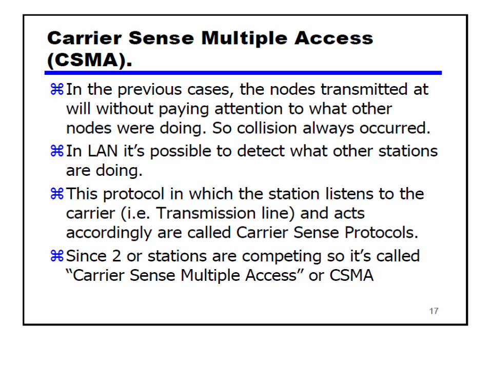
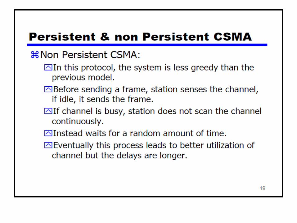
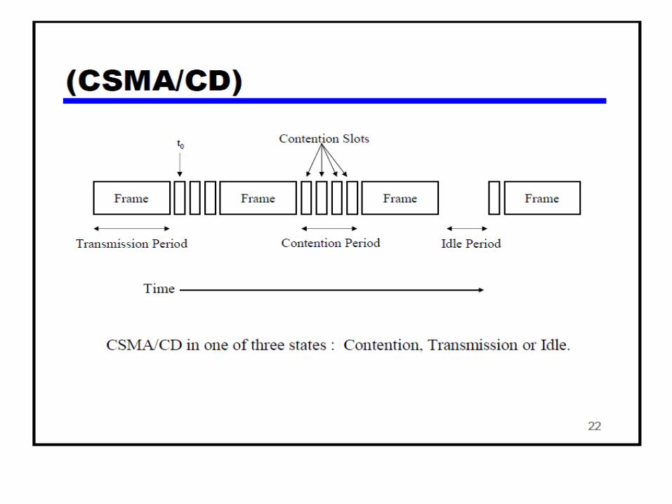
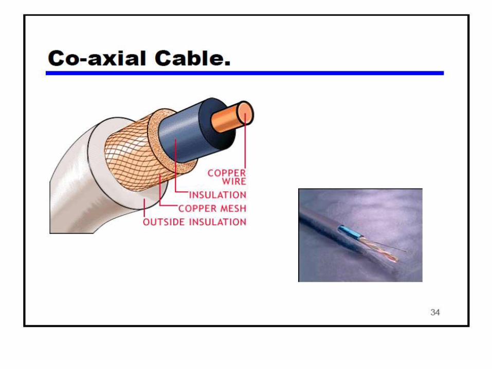
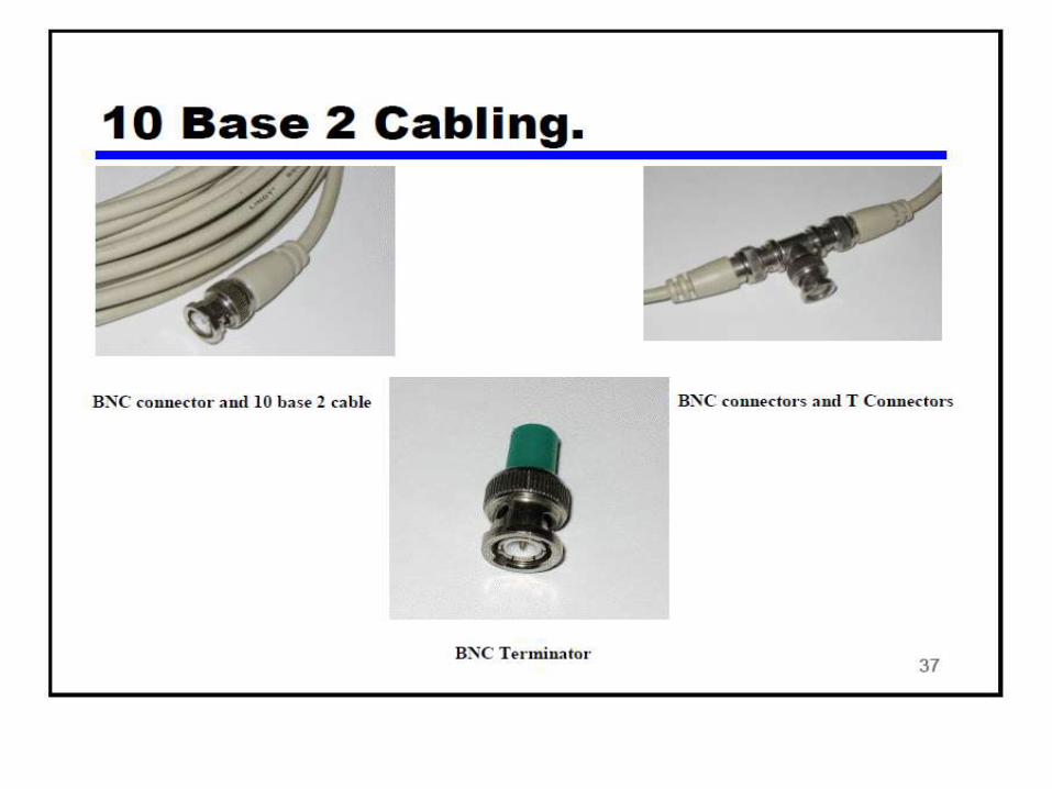
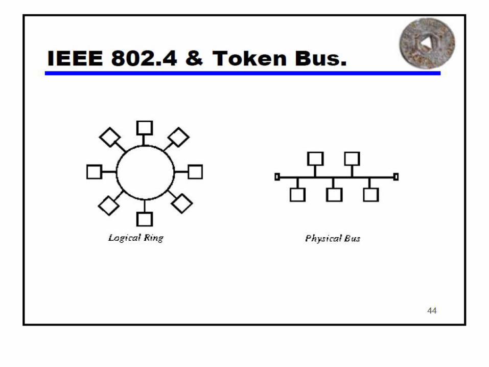
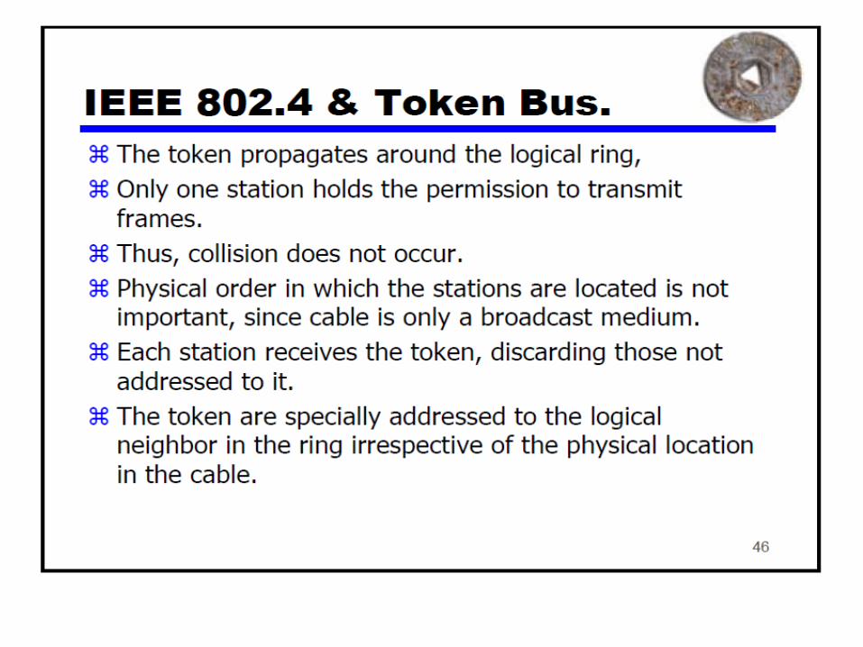
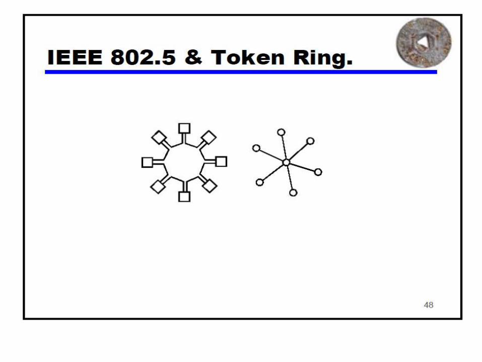
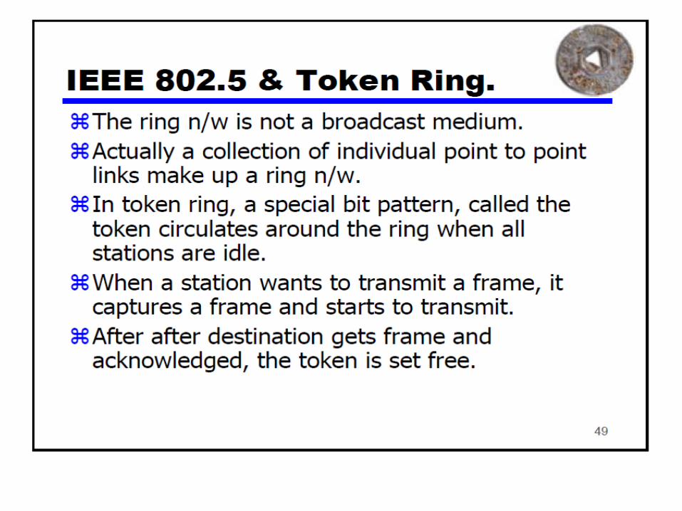
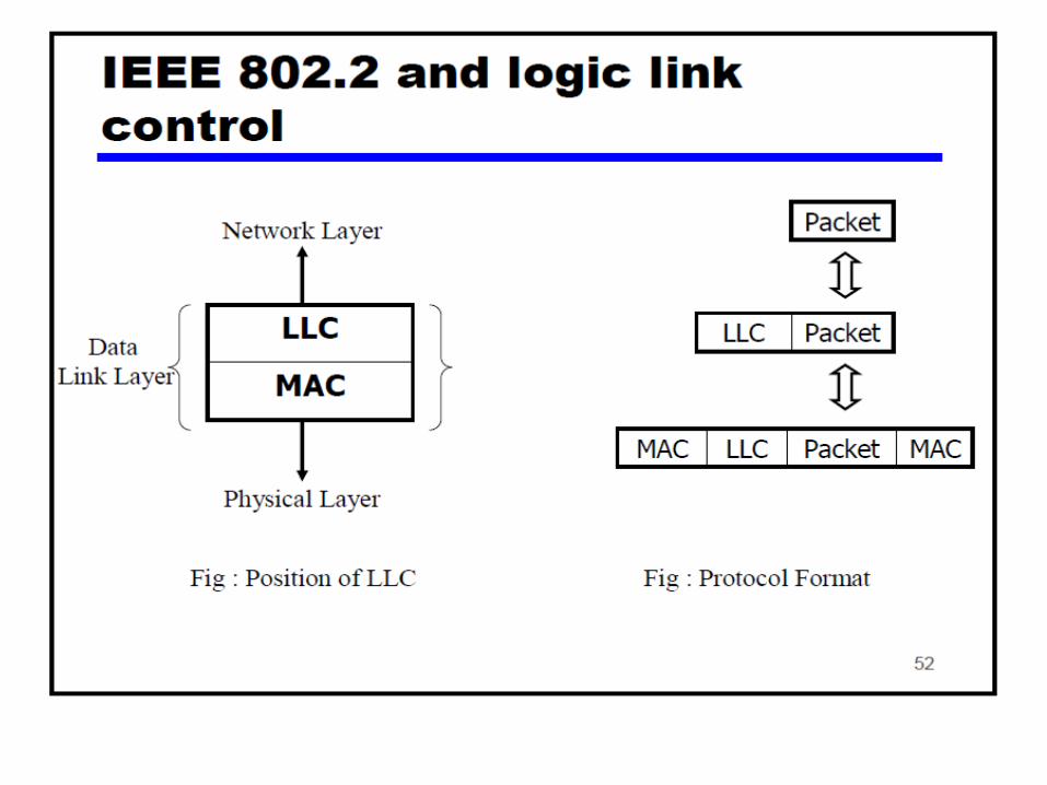
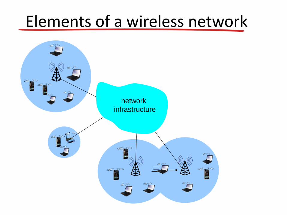
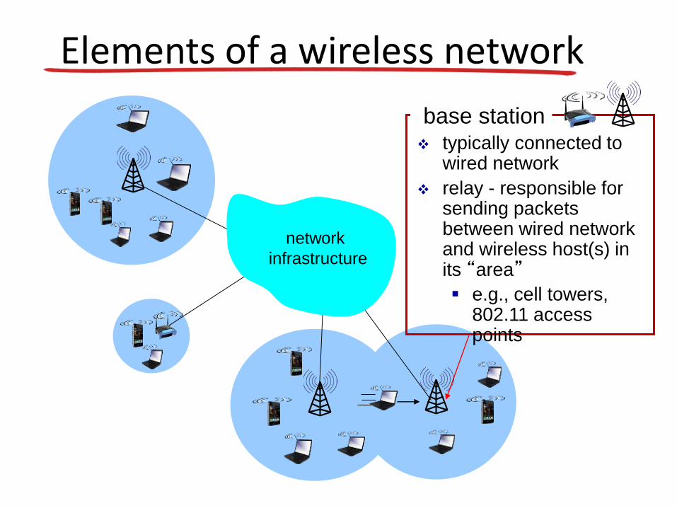
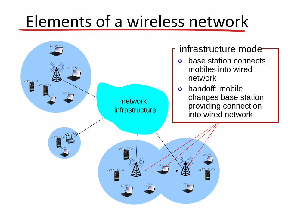
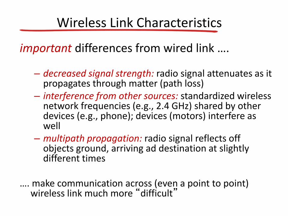
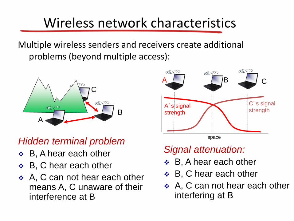
Slotted ALOHA
assumptions
all frames same size
time divided into equal size slots (time to transmit 1 frame)
nodes start to transmit only slot beginning
nodes are synchronized
if 2 or more nodes transmit in slot all nodes detect collision
operation when node obtains fresh
frame transmits in next slot
if no collision node can send new frame in next slot
if collision node retransmits frame in each subsequent slot with prob p until success
Pros
single active node can continuously transmit at full rate of channel
highly decentralized only slots in nodes need to be in sync
simple
Cons collisions wasting slots
idle slots
nodes may be able to detect collision in less than time to transmit packet
clock synchronization
Slotted ALOHA
1 1 1 1
2
3
2 2
3 3
node 1
node 2
node 3
C C CS S SE E E
suppose N nodes with many frames to send each transmits in slot with probability p
prob that given node has success in a slot = p(1-p)N-1
prob that any node has a success = Np(1-p)N-1
max efficiency find p that maximizes Np(1-p)N-1
for many nodes take limit of Np(1-p)N-1 as N goes to infinity gives
max efficiency = 1e = 37
efficiency long-run fraction of successful slots (many nodes all with many frames to send)
at best channelused for useful transmissions 37of time
Slotted ALOHA efficiency
Pure (unslotted) ALOHA
unslotted Aloha simpler no synchronization
when frame first arrives
transmit immediately
collision probability increases
frame sent at t0 collides with other frames sent in [t0-1t0+1]
Pure ALOHA efficiency
P(success by given node) = P(node transmits)
P(no other node transmits in [t0-1t0]
P(no other node transmits in [t0-1t0]
= p (1-p)N-1 (1-p)N-1
= p (1-p)2(N-1)
hellip choosing optimum p and then letting n
= 1(2e) = 18
even worse than slotted Aloha
CSMA (carrier sense multiple access)
CSMA listen before transmitif channel sensed idle transmit entire frame
bull if channel sensed busy defer transmission
bull human analogy donrsquot interrupt others
CSMA collisions
bull collisions can still occur propagation delay means two nodes may not hear each otherrsquos transmission
bull collision entire packet transmission time wastedndash distance amp propagation
delay play role in in determining collision probability
spatial layout of nodes
CSMACD (collision detection)
CSMACD carrier sensing deferral as in CSMA
collisions detected within short time
colliding transmissions aborted reducing channel wastage
collision detection
easy in wired LANs measure signal strengths compare transmitted received signals
difficult in wireless LANs received signal strength overwhelmed by local transmission strength
human analogy the polite conversationalist
CSMACD (collision detection)
spatial layout of nodes
Ethernet CSMACD algorithm
1 NIC receives datagram from network layer creates frame
2 If NIC senses channel idle starts frame transmission If NIC senses channel busy waits until channel idle then transmits
3 If NIC transmits entire frame without detecting another transmission NIC is done with frame
4 If NIC detects another transmission while transmitting aborts and sends jam signal
5 After aborting NIC enters binary (exponential) backoff
ndash after mth collision NIC chooses K at random from 012 hellip 2m-1 NIC waits K512 bit times returns to Step 2
ndash longer backoff interval with more collisions
CSMACD efficiency
Tprop = max prop delay between 2 nodes in LAN
ttrans = time to transmit max-size frame
efficiency goes to 1
as tprop goes to 0
as ttrans goes to infinity
better performance than ALOHA and simple cheap
decentralized
transprop ttefficiency
51
1
ldquoTaking turnsrdquo MAC protocols
channel partitioning MAC protocols
ndash share channel efficiently and fairly at high load
ndash inefficient at low load delay in channel access 1N bandwidth allocated even if only 1 active node
random access MAC protocols
ndash efficient at low load single node can fully utilize channel
ndash high load collision overhead
ldquotaking turnsrdquo protocols
look for best of both worlds
pollingbull master node ldquoinvitesrdquo
slave nodes to transmit in turn
bull typically used with ldquodumbrdquo slave devices
bull concerns
ndash polling overhead
ndash latency
ndash single point of failure (master)
master
slaves
poll
data
data
ldquoTaking turnsrdquo MAC protocols
token passing control token passed
from one node to next sequentially
token message
concerns
token overhead
latency
single point of failure (token)
T
data
(nothing
to send)
T
ldquoTaking turnsrdquo MAC protocols
MAC addresses and ARP
bull 32-bit IP address
ndash network-layer address for interface
ndash used for layer 3 (network layer) forwarding
bull MAC (or LAN or physical or Ethernet) address
ndash function used lsquolocallyrdquo to get frame from one interface to another physically-connected interface (same network in IP-addressing sense)
ndash 48 bit MAC address (for most LANs) burned in NIC ROM also sometimes software settable
ndash eg 1A-2F-BB-76-09-AD
hexadecimal (base 16) notation
(each ldquonumberrdquo represents 4 bits)
LAN addresses and ARPeach adapter on LAN has unique LAN address
adapter
1A-2F-BB-76-09-AD
58-23-D7-FA-20-B0
0C-C4-11-6F-E3-98
71-65-F7-2B-08-53
LAN
(wired or
wireless)
LAN addresses (more)
MAC address allocation administered by IEEE
manufacturer buys portion of MAC address space (to assure uniqueness)
analogy
MAC address like Social Security Number
IP address like postal address
MAC flat address portability
can move LAN card from one LAN to another
IP hierarchical address not portable
address depends on IP subnet to which node is
ARP address resolution protocol
ARP table each IP node (host router) on LAN has table
IPMAC address mappings for some LAN nodes
lt IP address MAC address TTLgt
TTL (Time To Live) time after which address mapping will be forgotten (typically 20 min)
Question how to determine
interfacersquos MAC address
knowing its IP address
1A-2F-BB-76-09-AD
58-23-D7-FA-20-B0
0C-C4-11-6F-E3-98
71-65-F7-2B-08-53
LAN
137196723
137196778
137196714
137196788
ARP protocol same LAN
bull A wants to send datagram to B
ndash Brsquos MAC address not in Arsquos ARP table
bull A broadcasts ARP query packet containing Bs IP address ndash dest MAC address = FF-FF-
FF-FF-FF-FF
ndash all nodes on LAN receive ARP query
bull B receives ARP packet replies to A with its (Bs) MAC address
ndash frame sent to Arsquos MAC address (unicast)
bull A caches (saves) IP-to-MAC address pair in its ARP table until information becomes old (times out)ndash soft state information that
times out (goes away) unless refreshed
bull ARP is ldquoplug-and-playrdquondash nodes create their ARP
tables without intervention from net administrator
walkthrough send datagram from A to B via R
ndash focus on addressing ndash at IP (datagram) and MAC layer (frame)
ndash assume A knows Brsquos IP address
ndash assume A knows IP address of first hop router R (how)
ndash assume A knows Rrsquos MAC address (how)
Addressing routing to another LAN
R
1A-23-F9-CD-06-9B222222222220
111111111110E6-E9-00-17-BB-4BCC-49-DE-D0-AB-7D
111111111112
111111111111
74-29-9C-E8-FF-55
A
222222222222
49-BD-D2-C7-56-2A
22222222222188-B2-2F-54-1A-0F
B
R
1A-23-F9-CD-06-9B222222222220
111111111110E6-E9-00-17-BB-4BCC-49-DE-D0-AB-7D
111111111112
111111111111
74-29-9C-E8-FF-55
A
222222222222
49-BD-D2-C7-56-2A
22222222222188-B2-2F-54-1A-0F
B
Addressing routing to another LAN
IP
Eth
Phy
IP src 111111111111
IP dest 222222222222
A creates IP datagram with IP source A destination B
A creates link-layer frame with Rs MAC address as dest frame contains A-to-B IP datagram
MAC src 74-29-9C-E8-FF-55
MAC dest E6-E9-00-17-BB-4B
R
1A-23-F9-CD-06-9B222222222220
111111111110E6-E9-00-17-BB-4BCC-49-DE-D0-AB-7D
111111111112
111111111111
74-29-9C-E8-FF-55
A
222222222222
49-BD-D2-C7-56-2A
22222222222188-B2-2F-54-1A-0F
B
Addressing routing to another LAN
IP
Eth
Phy
frame sent from A to R
IP
Eth
Phy
frame received at R datagram removed passed up to IP
MAC src 74-29-9C-E8-FF-55
MAC dest E6-E9-00-17-BB-4B
IP src 111111111111
IP dest 222222222222
IP src 111111111111
IP dest 222222222222
R
1A-23-F9-CD-06-9B222222222220
111111111110E6-E9-00-17-BB-4BCC-49-DE-D0-AB-7D
111111111112
111111111111
74-29-9C-E8-FF-55
A
222222222222
49-BD-D2-C7-56-2A
22222222222188-B2-2F-54-1A-0F
B
Addressing routing to another LAN
IP src 111111111111
IP dest 222222222222
R forwards datagram with IP source A destination B
R creates link-layer frame with Bs MAC address as dest frame contains A-to-B IP datagram
MAC src 1A-23-F9-CD-06-9B
MAC dest 49-BD-D2-C7-56-2A
IP
Eth
Phy
IP
Eth
Phy
R
1A-23-F9-CD-06-9B222222222220
111111111110E6-E9-00-17-BB-4BCC-49-DE-D0-AB-7D
111111111112
111111111111
74-29-9C-E8-FF-55
A
222222222222
49-BD-D2-C7-56-2A
22222222222188-B2-2F-54-1A-0F
B
Addressing routing to another LAN R forwards datagram with IP source A destination B
R creates link-layer frame with Bs MAC address as dest frame contains A-to-B IP datagram
IP src 111111111111
IP dest 222222222222
MAC src 1A-23-F9-CD-06-9B
MAC dest 49-BD-D2-C7-56-2A
IP
Eth
Phy
IP
Eth
Phy
R
1A-23-F9-CD-06-9B222222222220
111111111110E6-E9-00-17-BB-4BCC-49-DE-D0-AB-7D
111111111112
111111111111
74-29-9C-E8-FF-55
A
222222222222
49-BD-D2-C7-56-2A
22222222222188-B2-2F-54-1A-0F
B
Addressing routing to another LAN R forwards datagram with IP source A destination B
R creates link-layer frame with Bs MAC address as dest frame contains A-to-B IP datagram
IP src 111111111111
IP dest 222222222222
MAC src 1A-23-F9-CD-06-9B
MAC dest 49-BD-D2-C7-56-2A
IP
Eth
Phy
Ethernet
ldquodominantrdquo wired LAN technology
bull cheap $20 for NIC
bull first widely used LAN technology
bull simpler cheaper than token LANs and ATM
bull kept up with speed race 10 Mbps ndash 10 Gbps
Metcalfersquos Ethernet sketch
Ethernet physical topology
bull bus popular through mid 90sndash all nodes in same collision domain (can collide with
each other)
bull star prevails todayndash active switch in center
ndash each ldquospokerdquo runs a (separate) Ethernet protocol (nodes do not collide with each other)
switch
bus coaxial cablestar
Ethernet frame structure
sending adapter encapsulates IP datagram (or other network layer protocol packet) in Ethernet frame
preamble
7 bytes with pattern 10101010 followed by one byte with pattern 10101011
used to synchronize receiver sender clock rates
destaddress
sourceaddress
data (payload) CRCpreamble
type
Ethernet frame structure (more)
addresses 6 byte source destination MAC addresses
if adapter receives frame with matching destination address or with broadcast address (eg ARP packet) it passes data in frame to network layer protocol
otherwise adapter discards frame
type indicates higher layer protocol (mostly IP but others possible eg Novell IPX AppleTalk)
CRC cyclic redundancy check at receiver
error detected frame is dropped
destaddress
sourceaddress
data (payload) CRCpreamble
type
Ethernet unreliable connectionless
bull connectionless no handshaking between sending and receiving NICs
bull unreliable receiving NIC doesnt send acks or nacks to sending NIC
ndash data in dropped frames recovered only if initial sender uses higher layer rdt (eg TCP) otherwise dropped data lost
Switch multiple simultaneous transmissions
bull hosts have dedicated direct connection to switch
bull switches buffer packets
bull Ethernet protocol used on eachincoming link but no collisions full duplex
ndash each link is its own collision domain
bull switching A-to-Arsquo and B-to-Brsquocan transmit simultaneously without collisions switch with six interfaces
(123456)
A
Arsquo
B
Brsquo C
Crsquo
1 2
345
6
Switch forwarding table
Q how does switch know Arsquo reachable via interface 4 Brsquo reachable via interface 5
switch with six interfaces
(123456)
A
Arsquo
B
Brsquo C
Crsquo
1 2
345
6 A each switch has a switch table each entry
(MAC address of host
interface to reach host time
stamp)
looks like a routing table
Q how are entries created maintained in switch table
something like a routing protocol
A
Arsquo
B
Brsquo C
Crsquo
1 2
345
6
Switch self-learning
bull switch learns which hosts can be reached through which interfaces
ndash when frame received switch ldquolearnsrdquo location of sender incoming LAN segment
ndash records senderlocation pair in switch table
A Arsquo
Source A
Dest Arsquo
MAC addr interface TTL
Switch table
(initially empty)A 1 60
A
Arsquo
B
Brsquo C
Crsquo
1 2
345
6
Self-learning forwarding example
A Arsquo
Source A
Dest Arsquo
MAC addr interface TTL
switch table
(initially empty)A 1 60
A ArsquoA ArsquoA ArsquoA ArsquoA Arsquo
bull frame destination Arsquo locaton unknownflood
Arsquo A
destination A location
known
Arsquo 4 60
selectively send
on just one link
Interconnecting switches
switches can be connected together
Q sending from A to G - how does S1 know to forward frame destined to F via S4 and S3
A self learning (works exactly the same as in single-switch case)
A
B
S1
C D
E
F
S2
S4
S3
H
I
G
Self-learning multi-switch example
Suppose C sends frame to I I responds to C
Q show switch tables and packet forwarding in S1 S2 S3 S4
A
B
S1
C D
E
F
S2
S4
S3
H
I
G
Switches vs routers
both are store-and-forward
routers network-layer devices (examine network-layer headers)
switches link-layer devices (examine link-layer headers)
both have forwarding tables routers compute tables
using routing algorithms IP addresses
switches learn forwarding table using flooding learning MAC addresses
application
transport
network
link
physical
network
link
physical
link
physical
switch
datagram
application
transport
network
link
physical
frame
frame
frame
datagram
VLANs motivation
consider CS user moves office to EE
but wants connect to CS switch
single broadcast domain
all layer-2 broadcast traffic (ARP DHCP unknown location of destination MAC address) must cross entire LAN
securityprivacy efficiency issues
Computer
Science Electrical
Engineering
Computer
Engineering
VLANsport-based VLAN switch ports
grouped (by switch management software) so that single physical switch helliphellip
switch(es) supporting
VLAN capabilities can
be configured to
define multiple virtual
LANS over single
physical LAN
infrastructure
Virtual Local
Area Network1
8
9
16102
7
hellip
Electrical Engineering
(VLAN ports 1-8)
Computer Science
(VLAN ports 9-15)
15
hellip
Electrical Engineering
(VLAN ports 1-8)
hellip
1
82
7 9
1610
15
hellip
Computer Science
(VLAN ports 9-16)
hellip operates as multiple virtual switches
Port-based VLAN
1
8
9
16102
7
hellip
Electrical Engineering
(VLAN ports 1-8)
Computer Science
(VLAN ports 9-15)
15
hellip
traffic isolation frames tofrom ports 1-8 can onlyreach ports 1-8 can also define VLAN based on
MAC addresses of endpoints rather than switch port
dynamic membershipports can be dynamically assigned among VLANs
router
forwarding between VLANSdone via routing (just as with separate switches) in practice vendors sell combined
switches plus routers
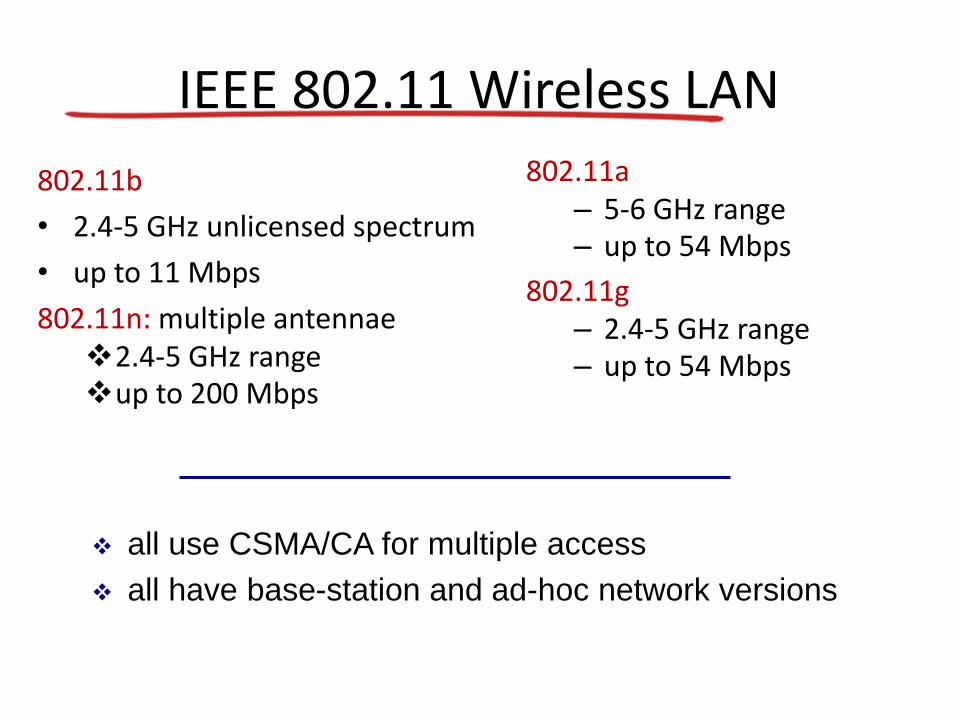
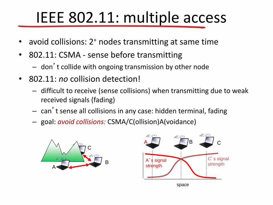

CSMACD (collision detection)
spatial layout of nodes
Ethernet CSMACD algorithm
1 NIC receives datagram from network layer creates frame
2 If NIC senses channel idle starts frame transmission If NIC senses channel busy waits until channel idle then transmits
3 If NIC transmits entire frame without detecting another transmission NIC is done with frame
4 If NIC detects another transmission while transmitting aborts and sends jam signal
5 After aborting NIC enters binary (exponential) backoff
ndash after mth collision NIC chooses K at random from 012 hellip 2m-1 NIC waits K512 bit times returns to Step 2
ndash longer backoff interval with more collisions
CSMACD efficiency
Tprop = max prop delay between 2 nodes in LAN
ttrans = time to transmit max-size frame
efficiency goes to 1
as tprop goes to 0
as ttrans goes to infinity
better performance than ALOHA and simple cheap
decentralized
transprop ttefficiency
51
1
ldquoTaking turnsrdquo MAC protocols
channel partitioning MAC protocols
ndash share channel efficiently and fairly at high load
ndash inefficient at low load delay in channel access 1N bandwidth allocated even if only 1 active node
random access MAC protocols
ndash efficient at low load single node can fully utilize channel
ndash high load collision overhead
ldquotaking turnsrdquo protocols
look for best of both worlds
pollingbull master node ldquoinvitesrdquo
slave nodes to transmit in turn
bull typically used with ldquodumbrdquo slave devices
bull concerns
ndash polling overhead
ndash latency
ndash single point of failure (master)
master
slaves
poll
data
data
ldquoTaking turnsrdquo MAC protocols
token passing control token passed
from one node to next sequentially
token message
concerns
token overhead
latency
single point of failure (token)
T
data
(nothing
to send)
T
ldquoTaking turnsrdquo MAC protocols
MAC addresses and ARP
bull 32-bit IP address
ndash network-layer address for interface
ndash used for layer 3 (network layer) forwarding
bull MAC (or LAN or physical or Ethernet) address
ndash function used lsquolocallyrdquo to get frame from one interface to another physically-connected interface (same network in IP-addressing sense)
ndash 48 bit MAC address (for most LANs) burned in NIC ROM also sometimes software settable
ndash eg 1A-2F-BB-76-09-AD
hexadecimal (base 16) notation
(each ldquonumberrdquo represents 4 bits)
LAN addresses and ARPeach adapter on LAN has unique LAN address
adapter
1A-2F-BB-76-09-AD
58-23-D7-FA-20-B0
0C-C4-11-6F-E3-98
71-65-F7-2B-08-53
LAN
(wired or
wireless)
LAN addresses (more)
MAC address allocation administered by IEEE
manufacturer buys portion of MAC address space (to assure uniqueness)
analogy
MAC address like Social Security Number
IP address like postal address
MAC flat address portability
can move LAN card from one LAN to another
IP hierarchical address not portable
address depends on IP subnet to which node is
ARP address resolution protocol
ARP table each IP node (host router) on LAN has table
IPMAC address mappings for some LAN nodes
lt IP address MAC address TTLgt
TTL (Time To Live) time after which address mapping will be forgotten (typically 20 min)
Question how to determine
interfacersquos MAC address
knowing its IP address
1A-2F-BB-76-09-AD
58-23-D7-FA-20-B0
0C-C4-11-6F-E3-98
71-65-F7-2B-08-53
LAN
137196723
137196778
137196714
137196788
ARP protocol same LAN
bull A wants to send datagram to B
ndash Brsquos MAC address not in Arsquos ARP table
bull A broadcasts ARP query packet containing Bs IP address ndash dest MAC address = FF-FF-
FF-FF-FF-FF
ndash all nodes on LAN receive ARP query
bull B receives ARP packet replies to A with its (Bs) MAC address
ndash frame sent to Arsquos MAC address (unicast)
bull A caches (saves) IP-to-MAC address pair in its ARP table until information becomes old (times out)ndash soft state information that
times out (goes away) unless refreshed
bull ARP is ldquoplug-and-playrdquondash nodes create their ARP
tables without intervention from net administrator
walkthrough send datagram from A to B via R
ndash focus on addressing ndash at IP (datagram) and MAC layer (frame)
ndash assume A knows Brsquos IP address
ndash assume A knows IP address of first hop router R (how)
ndash assume A knows Rrsquos MAC address (how)
Addressing routing to another LAN
R
1A-23-F9-CD-06-9B222222222220
111111111110E6-E9-00-17-BB-4BCC-49-DE-D0-AB-7D
111111111112
111111111111
74-29-9C-E8-FF-55
A
222222222222
49-BD-D2-C7-56-2A
22222222222188-B2-2F-54-1A-0F
B
R
1A-23-F9-CD-06-9B222222222220
111111111110E6-E9-00-17-BB-4BCC-49-DE-D0-AB-7D
111111111112
111111111111
74-29-9C-E8-FF-55
A
222222222222
49-BD-D2-C7-56-2A
22222222222188-B2-2F-54-1A-0F
B
Addressing routing to another LAN
IP
Eth
Phy
IP src 111111111111
IP dest 222222222222
A creates IP datagram with IP source A destination B
A creates link-layer frame with Rs MAC address as dest frame contains A-to-B IP datagram
MAC src 74-29-9C-E8-FF-55
MAC dest E6-E9-00-17-BB-4B
R
1A-23-F9-CD-06-9B222222222220
111111111110E6-E9-00-17-BB-4BCC-49-DE-D0-AB-7D
111111111112
111111111111
74-29-9C-E8-FF-55
A
222222222222
49-BD-D2-C7-56-2A
22222222222188-B2-2F-54-1A-0F
B
Addressing routing to another LAN
IP
Eth
Phy
frame sent from A to R
IP
Eth
Phy
frame received at R datagram removed passed up to IP
MAC src 74-29-9C-E8-FF-55
MAC dest E6-E9-00-17-BB-4B
IP src 111111111111
IP dest 222222222222
IP src 111111111111
IP dest 222222222222
R
1A-23-F9-CD-06-9B222222222220
111111111110E6-E9-00-17-BB-4BCC-49-DE-D0-AB-7D
111111111112
111111111111
74-29-9C-E8-FF-55
A
222222222222
49-BD-D2-C7-56-2A
22222222222188-B2-2F-54-1A-0F
B
Addressing routing to another LAN
IP src 111111111111
IP dest 222222222222
R forwards datagram with IP source A destination B
R creates link-layer frame with Bs MAC address as dest frame contains A-to-B IP datagram
MAC src 1A-23-F9-CD-06-9B
MAC dest 49-BD-D2-C7-56-2A
IP
Eth
Phy
IP
Eth
Phy
R
1A-23-F9-CD-06-9B222222222220
111111111110E6-E9-00-17-BB-4BCC-49-DE-D0-AB-7D
111111111112
111111111111
74-29-9C-E8-FF-55
A
222222222222
49-BD-D2-C7-56-2A
22222222222188-B2-2F-54-1A-0F
B
Addressing routing to another LAN R forwards datagram with IP source A destination B
R creates link-layer frame with Bs MAC address as dest frame contains A-to-B IP datagram
IP src 111111111111
IP dest 222222222222
MAC src 1A-23-F9-CD-06-9B
MAC dest 49-BD-D2-C7-56-2A
IP
Eth
Phy
IP
Eth
Phy
R
1A-23-F9-CD-06-9B222222222220
111111111110E6-E9-00-17-BB-4BCC-49-DE-D0-AB-7D
111111111112
111111111111
74-29-9C-E8-FF-55
A
222222222222
49-BD-D2-C7-56-2A
22222222222188-B2-2F-54-1A-0F
B
Addressing routing to another LAN R forwards datagram with IP source A destination B
R creates link-layer frame with Bs MAC address as dest frame contains A-to-B IP datagram
IP src 111111111111
IP dest 222222222222
MAC src 1A-23-F9-CD-06-9B
MAC dest 49-BD-D2-C7-56-2A
IP
Eth
Phy
Ethernet
ldquodominantrdquo wired LAN technology
bull cheap $20 for NIC
bull first widely used LAN technology
bull simpler cheaper than token LANs and ATM
bull kept up with speed race 10 Mbps ndash 10 Gbps
Metcalfersquos Ethernet sketch
Ethernet physical topology
bull bus popular through mid 90sndash all nodes in same collision domain (can collide with
each other)
bull star prevails todayndash active switch in center
ndash each ldquospokerdquo runs a (separate) Ethernet protocol (nodes do not collide with each other)
switch
bus coaxial cablestar
Ethernet frame structure
sending adapter encapsulates IP datagram (or other network layer protocol packet) in Ethernet frame
preamble
7 bytes with pattern 10101010 followed by one byte with pattern 10101011
used to synchronize receiver sender clock rates
destaddress
sourceaddress
data (payload) CRCpreamble
type
Ethernet frame structure (more)
addresses 6 byte source destination MAC addresses
if adapter receives frame with matching destination address or with broadcast address (eg ARP packet) it passes data in frame to network layer protocol
otherwise adapter discards frame
type indicates higher layer protocol (mostly IP but others possible eg Novell IPX AppleTalk)
CRC cyclic redundancy check at receiver
error detected frame is dropped
destaddress
sourceaddress
data (payload) CRCpreamble
type
Ethernet unreliable connectionless
bull connectionless no handshaking between sending and receiving NICs
bull unreliable receiving NIC doesnt send acks or nacks to sending NIC
ndash data in dropped frames recovered only if initial sender uses higher layer rdt (eg TCP) otherwise dropped data lost
Switch multiple simultaneous transmissions
bull hosts have dedicated direct connection to switch
bull switches buffer packets
bull Ethernet protocol used on eachincoming link but no collisions full duplex
ndash each link is its own collision domain
bull switching A-to-Arsquo and B-to-Brsquocan transmit simultaneously without collisions switch with six interfaces
(123456)
A
Arsquo
B
Brsquo C
Crsquo
1 2
345
6
Switch forwarding table
Q how does switch know Arsquo reachable via interface 4 Brsquo reachable via interface 5
switch with six interfaces
(123456)
A
Arsquo
B
Brsquo C
Crsquo
1 2
345
6 A each switch has a switch table each entry
(MAC address of host
interface to reach host time
stamp)
looks like a routing table
Q how are entries created maintained in switch table
something like a routing protocol
A
Arsquo
B
Brsquo C
Crsquo
1 2
345
6
Switch self-learning
bull switch learns which hosts can be reached through which interfaces
ndash when frame received switch ldquolearnsrdquo location of sender incoming LAN segment
ndash records senderlocation pair in switch table
A Arsquo
Source A
Dest Arsquo
MAC addr interface TTL
Switch table
(initially empty)A 1 60
A
Arsquo
B
Brsquo C
Crsquo
1 2
345
6
Self-learning forwarding example
A Arsquo
Source A
Dest Arsquo
MAC addr interface TTL
switch table
(initially empty)A 1 60
A ArsquoA ArsquoA ArsquoA ArsquoA Arsquo
bull frame destination Arsquo locaton unknownflood
Arsquo A
destination A location
known
Arsquo 4 60
selectively send
on just one link
Interconnecting switches
switches can be connected together
Q sending from A to G - how does S1 know to forward frame destined to F via S4 and S3
A self learning (works exactly the same as in single-switch case)
A
B
S1
C D
E
F
S2
S4
S3
H
I
G
Self-learning multi-switch example
Suppose C sends frame to I I responds to C
Q show switch tables and packet forwarding in S1 S2 S3 S4
A
B
S1
C D
E
F
S2
S4
S3
H
I
G
Switches vs routers
both are store-and-forward
routers network-layer devices (examine network-layer headers)
switches link-layer devices (examine link-layer headers)
both have forwarding tables routers compute tables
using routing algorithms IP addresses
switches learn forwarding table using flooding learning MAC addresses
application
transport
network
link
physical
network
link
physical
link
physical
switch
datagram
application
transport
network
link
physical
frame
frame
frame
datagram
VLANs motivation
consider CS user moves office to EE
but wants connect to CS switch
single broadcast domain
all layer-2 broadcast traffic (ARP DHCP unknown location of destination MAC address) must cross entire LAN
securityprivacy efficiency issues
Computer
Science Electrical
Engineering
Computer
Engineering
VLANsport-based VLAN switch ports
grouped (by switch management software) so that single physical switch helliphellip
switch(es) supporting
VLAN capabilities can
be configured to
define multiple virtual
LANS over single
physical LAN
infrastructure
Virtual Local
Area Network1
8
9
16102
7
hellip
Electrical Engineering
(VLAN ports 1-8)
Computer Science
(VLAN ports 9-15)
15
hellip
Electrical Engineering
(VLAN ports 1-8)
hellip
1
82
7 9
1610
15
hellip
Computer Science
(VLAN ports 9-16)
hellip operates as multiple virtual switches
Port-based VLAN
1
8
9
16102
7
hellip
Electrical Engineering
(VLAN ports 1-8)
Computer Science
(VLAN ports 9-15)
15
hellip
traffic isolation frames tofrom ports 1-8 can onlyreach ports 1-8 can also define VLAN based on
MAC addresses of endpoints rather than switch port
dynamic membershipports can be dynamically assigned among VLANs
router
forwarding between VLANSdone via routing (just as with separate switches) in practice vendors sell combined
switches plus routers
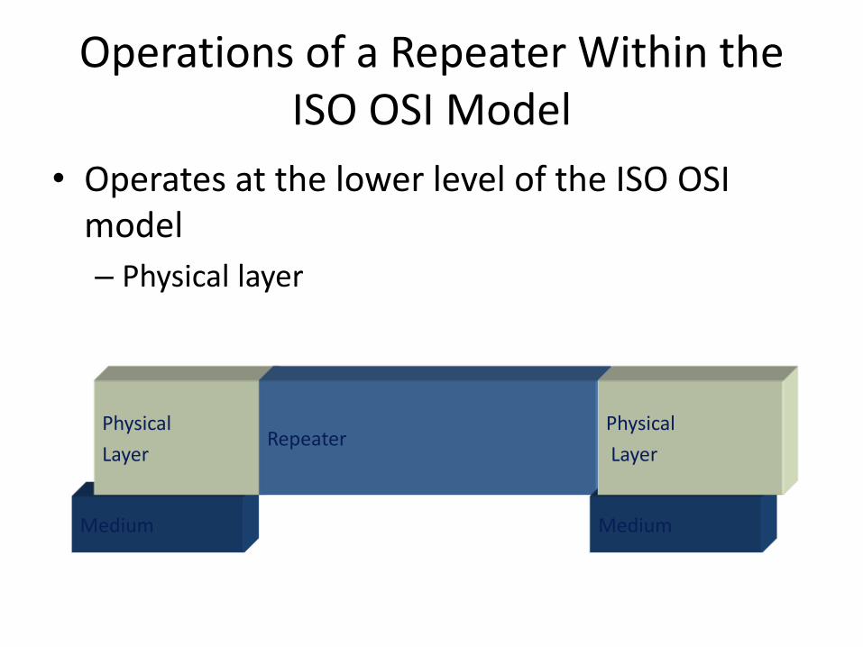
ldquoTaking turnsrdquo MAC protocols
channel partitioning MAC protocols
ndash share channel efficiently and fairly at high load
ndash inefficient at low load delay in channel access 1N bandwidth allocated even if only 1 active node
random access MAC protocols
ndash efficient at low load single node can fully utilize channel
ndash high load collision overhead
ldquotaking turnsrdquo protocols
look for best of both worlds
pollingbull master node ldquoinvitesrdquo
slave nodes to transmit in turn
bull typically used with ldquodumbrdquo slave devices
bull concerns
ndash polling overhead
ndash latency
ndash single point of failure (master)
master
slaves
poll
data
data
ldquoTaking turnsrdquo MAC protocols
token passing control token passed
from one node to next sequentially
token message
concerns
token overhead
latency
single point of failure (token)
T
data
(nothing
to send)
T
ldquoTaking turnsrdquo MAC protocols
MAC addresses and ARP
bull 32-bit IP address
ndash network-layer address for interface
ndash used for layer 3 (network layer) forwarding
bull MAC (or LAN or physical or Ethernet) address
ndash function used lsquolocallyrdquo to get frame from one interface to another physically-connected interface (same network in IP-addressing sense)
ndash 48 bit MAC address (for most LANs) burned in NIC ROM also sometimes software settable
ndash eg 1A-2F-BB-76-09-AD
hexadecimal (base 16) notation
(each ldquonumberrdquo represents 4 bits)
LAN addresses and ARPeach adapter on LAN has unique LAN address
adapter
1A-2F-BB-76-09-AD
58-23-D7-FA-20-B0
0C-C4-11-6F-E3-98
71-65-F7-2B-08-53
LAN
(wired or
wireless)
LAN addresses (more)
MAC address allocation administered by IEEE
manufacturer buys portion of MAC address space (to assure uniqueness)
analogy
MAC address like Social Security Number
IP address like postal address
MAC flat address portability
can move LAN card from one LAN to another
IP hierarchical address not portable
address depends on IP subnet to which node is
ARP address resolution protocol
ARP table each IP node (host router) on LAN has table
IPMAC address mappings for some LAN nodes
lt IP address MAC address TTLgt
TTL (Time To Live) time after which address mapping will be forgotten (typically 20 min)
Question how to determine
interfacersquos MAC address
knowing its IP address
1A-2F-BB-76-09-AD
58-23-D7-FA-20-B0
0C-C4-11-6F-E3-98
71-65-F7-2B-08-53
LAN
137196723
137196778
137196714
137196788
ARP protocol same LAN
bull A wants to send datagram to B
ndash Brsquos MAC address not in Arsquos ARP table
bull A broadcasts ARP query packet containing Bs IP address ndash dest MAC address = FF-FF-
FF-FF-FF-FF
ndash all nodes on LAN receive ARP query
bull B receives ARP packet replies to A with its (Bs) MAC address
ndash frame sent to Arsquos MAC address (unicast)
bull A caches (saves) IP-to-MAC address pair in its ARP table until information becomes old (times out)ndash soft state information that
times out (goes away) unless refreshed
bull ARP is ldquoplug-and-playrdquondash nodes create their ARP
tables without intervention from net administrator
walkthrough send datagram from A to B via R
ndash focus on addressing ndash at IP (datagram) and MAC layer (frame)
ndash assume A knows Brsquos IP address
ndash assume A knows IP address of first hop router R (how)
ndash assume A knows Rrsquos MAC address (how)
Addressing routing to another LAN
R
1A-23-F9-CD-06-9B222222222220
111111111110E6-E9-00-17-BB-4BCC-49-DE-D0-AB-7D
111111111112
111111111111
74-29-9C-E8-FF-55
A
222222222222
49-BD-D2-C7-56-2A
22222222222188-B2-2F-54-1A-0F
B
R
1A-23-F9-CD-06-9B222222222220
111111111110E6-E9-00-17-BB-4BCC-49-DE-D0-AB-7D
111111111112
111111111111
74-29-9C-E8-FF-55
A
222222222222
49-BD-D2-C7-56-2A
22222222222188-B2-2F-54-1A-0F
B
Addressing routing to another LAN
IP
Eth
Phy
IP src 111111111111
IP dest 222222222222
A creates IP datagram with IP source A destination B
A creates link-layer frame with Rs MAC address as dest frame contains A-to-B IP datagram
MAC src 74-29-9C-E8-FF-55
MAC dest E6-E9-00-17-BB-4B
R
1A-23-F9-CD-06-9B222222222220
111111111110E6-E9-00-17-BB-4BCC-49-DE-D0-AB-7D
111111111112
111111111111
74-29-9C-E8-FF-55
A
222222222222
49-BD-D2-C7-56-2A
22222222222188-B2-2F-54-1A-0F
B
Addressing routing to another LAN
IP
Eth
Phy
frame sent from A to R
IP
Eth
Phy
frame received at R datagram removed passed up to IP
MAC src 74-29-9C-E8-FF-55
MAC dest E6-E9-00-17-BB-4B
IP src 111111111111
IP dest 222222222222
IP src 111111111111
IP dest 222222222222
R
1A-23-F9-CD-06-9B222222222220
111111111110E6-E9-00-17-BB-4BCC-49-DE-D0-AB-7D
111111111112
111111111111
74-29-9C-E8-FF-55
A
222222222222
49-BD-D2-C7-56-2A
22222222222188-B2-2F-54-1A-0F
B
Addressing routing to another LAN
IP src 111111111111
IP dest 222222222222
R forwards datagram with IP source A destination B
R creates link-layer frame with Bs MAC address as dest frame contains A-to-B IP datagram
MAC src 1A-23-F9-CD-06-9B
MAC dest 49-BD-D2-C7-56-2A
IP
Eth
Phy
IP
Eth
Phy
R
1A-23-F9-CD-06-9B222222222220
111111111110E6-E9-00-17-BB-4BCC-49-DE-D0-AB-7D
111111111112
111111111111
74-29-9C-E8-FF-55
A
222222222222
49-BD-D2-C7-56-2A
22222222222188-B2-2F-54-1A-0F
B
Addressing routing to another LAN R forwards datagram with IP source A destination B
R creates link-layer frame with Bs MAC address as dest frame contains A-to-B IP datagram
IP src 111111111111
IP dest 222222222222
MAC src 1A-23-F9-CD-06-9B
MAC dest 49-BD-D2-C7-56-2A
IP
Eth
Phy
IP
Eth
Phy
R
1A-23-F9-CD-06-9B222222222220
111111111110E6-E9-00-17-BB-4BCC-49-DE-D0-AB-7D
111111111112
111111111111
74-29-9C-E8-FF-55
A
222222222222
49-BD-D2-C7-56-2A
22222222222188-B2-2F-54-1A-0F
B
Addressing routing to another LAN R forwards datagram with IP source A destination B
R creates link-layer frame with Bs MAC address as dest frame contains A-to-B IP datagram
IP src 111111111111
IP dest 222222222222
MAC src 1A-23-F9-CD-06-9B
MAC dest 49-BD-D2-C7-56-2A
IP
Eth
Phy
Ethernet
ldquodominantrdquo wired LAN technology
bull cheap $20 for NIC
bull first widely used LAN technology
bull simpler cheaper than token LANs and ATM
bull kept up with speed race 10 Mbps ndash 10 Gbps
Metcalfersquos Ethernet sketch
Ethernet physical topology
bull bus popular through mid 90sndash all nodes in same collision domain (can collide with
each other)
bull star prevails todayndash active switch in center
ndash each ldquospokerdquo runs a (separate) Ethernet protocol (nodes do not collide with each other)
switch
bus coaxial cablestar
Ethernet frame structure
sending adapter encapsulates IP datagram (or other network layer protocol packet) in Ethernet frame
preamble
7 bytes with pattern 10101010 followed by one byte with pattern 10101011
used to synchronize receiver sender clock rates
destaddress
sourceaddress
data (payload) CRCpreamble
type
Ethernet frame structure (more)
addresses 6 byte source destination MAC addresses
if adapter receives frame with matching destination address or with broadcast address (eg ARP packet) it passes data in frame to network layer protocol
otherwise adapter discards frame
type indicates higher layer protocol (mostly IP but others possible eg Novell IPX AppleTalk)
CRC cyclic redundancy check at receiver
error detected frame is dropped
destaddress
sourceaddress
data (payload) CRCpreamble
type
Ethernet unreliable connectionless
bull connectionless no handshaking between sending and receiving NICs
bull unreliable receiving NIC doesnt send acks or nacks to sending NIC
ndash data in dropped frames recovered only if initial sender uses higher layer rdt (eg TCP) otherwise dropped data lost
Switch multiple simultaneous transmissions
bull hosts have dedicated direct connection to switch
bull switches buffer packets
bull Ethernet protocol used on eachincoming link but no collisions full duplex
ndash each link is its own collision domain
bull switching A-to-Arsquo and B-to-Brsquocan transmit simultaneously without collisions switch with six interfaces
(123456)
A
Arsquo
B
Brsquo C
Crsquo
1 2
345
6
Switch forwarding table
Q how does switch know Arsquo reachable via interface 4 Brsquo reachable via interface 5
switch with six interfaces
(123456)
A
Arsquo
B
Brsquo C
Crsquo
1 2
345
6 A each switch has a switch table each entry
(MAC address of host
interface to reach host time
stamp)
looks like a routing table
Q how are entries created maintained in switch table
something like a routing protocol
A
Arsquo
B
Brsquo C
Crsquo
1 2
345
6
Switch self-learning
bull switch learns which hosts can be reached through which interfaces
ndash when frame received switch ldquolearnsrdquo location of sender incoming LAN segment
ndash records senderlocation pair in switch table
A Arsquo
Source A
Dest Arsquo
MAC addr interface TTL
Switch table
(initially empty)A 1 60
A
Arsquo
B
Brsquo C
Crsquo
1 2
345
6
Self-learning forwarding example
A Arsquo
Source A
Dest Arsquo
MAC addr interface TTL
switch table
(initially empty)A 1 60
A ArsquoA ArsquoA ArsquoA ArsquoA Arsquo
bull frame destination Arsquo locaton unknownflood
Arsquo A
destination A location
known
Arsquo 4 60
selectively send
on just one link
Interconnecting switches
switches can be connected together
Q sending from A to G - how does S1 know to forward frame destined to F via S4 and S3
A self learning (works exactly the same as in single-switch case)
A
B
S1
C D
E
F
S2
S4
S3
H
I
G
Self-learning multi-switch example
Suppose C sends frame to I I responds to C
Q show switch tables and packet forwarding in S1 S2 S3 S4
A
B
S1
C D
E
F
S2
S4
S3
H
I
G
Switches vs routers
both are store-and-forward
routers network-layer devices (examine network-layer headers)
switches link-layer devices (examine link-layer headers)
both have forwarding tables routers compute tables
using routing algorithms IP addresses
switches learn forwarding table using flooding learning MAC addresses
application
transport
network
link
physical
network
link
physical
link
physical
switch
datagram
application
transport
network
link
physical
frame
frame
frame
datagram
VLANs motivation
consider CS user moves office to EE
but wants connect to CS switch
single broadcast domain
all layer-2 broadcast traffic (ARP DHCP unknown location of destination MAC address) must cross entire LAN
securityprivacy efficiency issues
Computer
Science Electrical
Engineering
Computer
Engineering
VLANsport-based VLAN switch ports
grouped (by switch management software) so that single physical switch helliphellip
switch(es) supporting
VLAN capabilities can
be configured to
define multiple virtual
LANS over single
physical LAN
infrastructure
Virtual Local
Area Network1
8
9
16102
7
hellip
Electrical Engineering
(VLAN ports 1-8)
Computer Science
(VLAN ports 9-15)
15
hellip
Electrical Engineering
(VLAN ports 1-8)
hellip
1
82
7 9
1610
15
hellip
Computer Science
(VLAN ports 9-16)
hellip operates as multiple virtual switches
Port-based VLAN
1
8
9
16102
7
hellip
Electrical Engineering
(VLAN ports 1-8)
Computer Science
(VLAN ports 9-15)
15
hellip
traffic isolation frames tofrom ports 1-8 can onlyreach ports 1-8 can also define VLAN based on
MAC addresses of endpoints rather than switch port
dynamic membershipports can be dynamically assigned among VLANs
router
forwarding between VLANSdone via routing (just as with separate switches) in practice vendors sell combined
switches plus routers
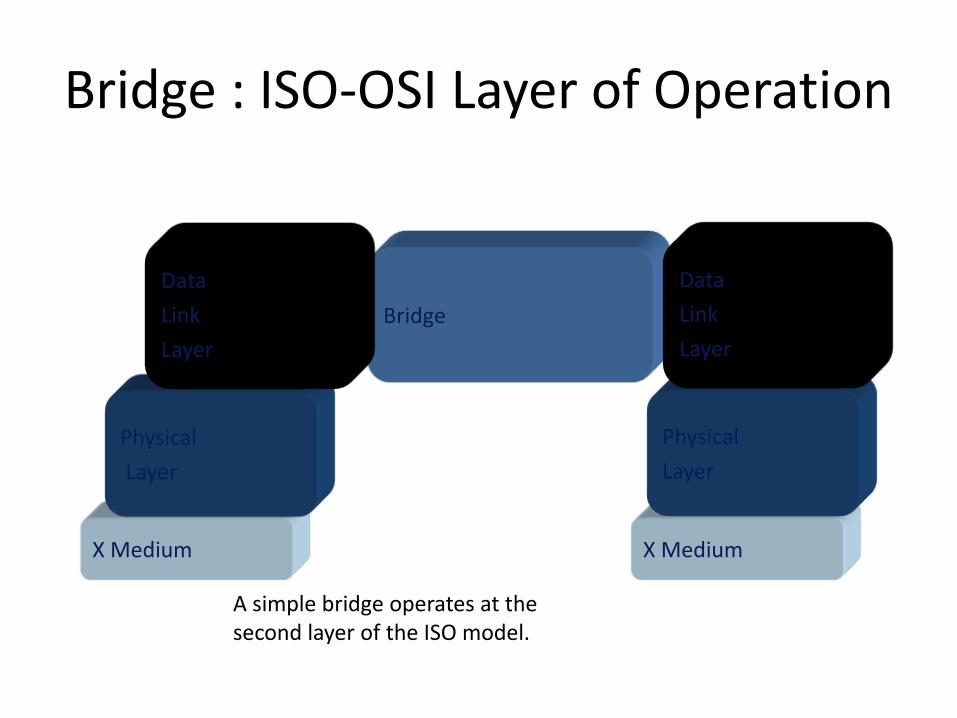
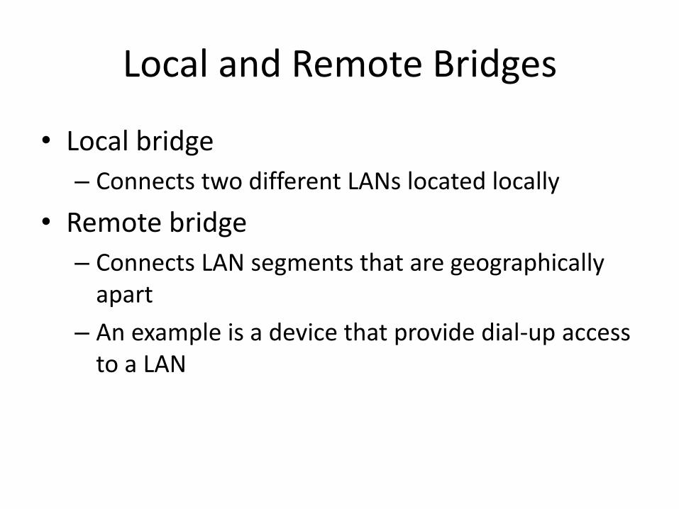

R
1A-23-F9-CD-06-9B222222222220
111111111110E6-E9-00-17-BB-4BCC-49-DE-D0-AB-7D
111111111112
111111111111
74-29-9C-E8-FF-55
A
222222222222
49-BD-D2-C7-56-2A
22222222222188-B2-2F-54-1A-0F
B
Addressing routing to another LAN
IP
Eth
Phy
IP src 111111111111
IP dest 222222222222
A creates IP datagram with IP source A destination B
A creates link-layer frame with Rs MAC address as dest frame contains A-to-B IP datagram
MAC src 74-29-9C-E8-FF-55
MAC dest E6-E9-00-17-BB-4B
R
1A-23-F9-CD-06-9B222222222220
111111111110E6-E9-00-17-BB-4BCC-49-DE-D0-AB-7D
111111111112
111111111111
74-29-9C-E8-FF-55
A
222222222222
49-BD-D2-C7-56-2A
22222222222188-B2-2F-54-1A-0F
B
Addressing routing to another LAN
IP
Eth
Phy
frame sent from A to R
IP
Eth
Phy
frame received at R datagram removed passed up to IP
MAC src 74-29-9C-E8-FF-55
MAC dest E6-E9-00-17-BB-4B
IP src 111111111111
IP dest 222222222222
IP src 111111111111
IP dest 222222222222
R
1A-23-F9-CD-06-9B222222222220
111111111110E6-E9-00-17-BB-4BCC-49-DE-D0-AB-7D
111111111112
111111111111
74-29-9C-E8-FF-55
A
222222222222
49-BD-D2-C7-56-2A
22222222222188-B2-2F-54-1A-0F
B
Addressing routing to another LAN
IP src 111111111111
IP dest 222222222222
R forwards datagram with IP source A destination B
R creates link-layer frame with Bs MAC address as dest frame contains A-to-B IP datagram
MAC src 1A-23-F9-CD-06-9B
MAC dest 49-BD-D2-C7-56-2A
IP
Eth
Phy
IP
Eth
Phy
R
1A-23-F9-CD-06-9B222222222220
111111111110E6-E9-00-17-BB-4BCC-49-DE-D0-AB-7D
111111111112
111111111111
74-29-9C-E8-FF-55
A
222222222222
49-BD-D2-C7-56-2A
22222222222188-B2-2F-54-1A-0F
B
Addressing routing to another LAN R forwards datagram with IP source A destination B
R creates link-layer frame with Bs MAC address as dest frame contains A-to-B IP datagram
IP src 111111111111
IP dest 222222222222
MAC src 1A-23-F9-CD-06-9B
MAC dest 49-BD-D2-C7-56-2A
IP
Eth
Phy
IP
Eth
Phy
R
1A-23-F9-CD-06-9B222222222220
111111111110E6-E9-00-17-BB-4BCC-49-DE-D0-AB-7D
111111111112
111111111111
74-29-9C-E8-FF-55
A
222222222222
49-BD-D2-C7-56-2A
22222222222188-B2-2F-54-1A-0F
B
Addressing routing to another LAN R forwards datagram with IP source A destination B
R creates link-layer frame with Bs MAC address as dest frame contains A-to-B IP datagram
IP src 111111111111
IP dest 222222222222
MAC src 1A-23-F9-CD-06-9B
MAC dest 49-BD-D2-C7-56-2A
IP
Eth
Phy
Ethernet
ldquodominantrdquo wired LAN technology
bull cheap $20 for NIC
bull first widely used LAN technology
bull simpler cheaper than token LANs and ATM
bull kept up with speed race 10 Mbps ndash 10 Gbps
Metcalfersquos Ethernet sketch
Ethernet physical topology
bull bus popular through mid 90sndash all nodes in same collision domain (can collide with
each other)
bull star prevails todayndash active switch in center
ndash each ldquospokerdquo runs a (separate) Ethernet protocol (nodes do not collide with each other)
switch
bus coaxial cablestar
Ethernet frame structure
sending adapter encapsulates IP datagram (or other network layer protocol packet) in Ethernet frame
preamble
7 bytes with pattern 10101010 followed by one byte with pattern 10101011
used to synchronize receiver sender clock rates
destaddress
sourceaddress
data (payload) CRCpreamble
type
Ethernet frame structure (more)
addresses 6 byte source destination MAC addresses
if adapter receives frame with matching destination address or with broadcast address (eg ARP packet) it passes data in frame to network layer protocol
otherwise adapter discards frame
type indicates higher layer protocol (mostly IP but others possible eg Novell IPX AppleTalk)
CRC cyclic redundancy check at receiver
error detected frame is dropped
destaddress
sourceaddress
data (payload) CRCpreamble
type
Ethernet unreliable connectionless
bull connectionless no handshaking between sending and receiving NICs
bull unreliable receiving NIC doesnt send acks or nacks to sending NIC
ndash data in dropped frames recovered only if initial sender uses higher layer rdt (eg TCP) otherwise dropped data lost
Switch multiple simultaneous transmissions
bull hosts have dedicated direct connection to switch
bull switches buffer packets
bull Ethernet protocol used on eachincoming link but no collisions full duplex
ndash each link is its own collision domain
bull switching A-to-Arsquo and B-to-Brsquocan transmit simultaneously without collisions switch with six interfaces
(123456)
A
Arsquo
B
Brsquo C
Crsquo
1 2
345
6
Switch forwarding table
Q how does switch know Arsquo reachable via interface 4 Brsquo reachable via interface 5
switch with six interfaces
(123456)
A
Arsquo
B
Brsquo C
Crsquo
1 2
345
6 A each switch has a switch table each entry
(MAC address of host
interface to reach host time
stamp)
looks like a routing table
Q how are entries created maintained in switch table
something like a routing protocol
A
Arsquo
B
Brsquo C
Crsquo
1 2
345
6
Switch self-learning
bull switch learns which hosts can be reached through which interfaces
ndash when frame received switch ldquolearnsrdquo location of sender incoming LAN segment
ndash records senderlocation pair in switch table
A Arsquo
Source A
Dest Arsquo
MAC addr interface TTL
Switch table
(initially empty)A 1 60
A
Arsquo
B
Brsquo C
Crsquo
1 2
345
6
Self-learning forwarding example
A Arsquo
Source A
Dest Arsquo
MAC addr interface TTL
switch table
(initially empty)A 1 60
A ArsquoA ArsquoA ArsquoA ArsquoA Arsquo
bull frame destination Arsquo locaton unknownflood
Arsquo A
destination A location
known
Arsquo 4 60
selectively send
on just one link
Interconnecting switches
switches can be connected together
Q sending from A to G - how does S1 know to forward frame destined to F via S4 and S3
A self learning (works exactly the same as in single-switch case)
A
B
S1
C D
E
F
S2
S4
S3
H
I
G
Self-learning multi-switch example
Suppose C sends frame to I I responds to C
Q show switch tables and packet forwarding in S1 S2 S3 S4
A
B
S1
C D
E
F
S2
S4
S3
H
I
G
Switches vs routers
both are store-and-forward
routers network-layer devices (examine network-layer headers)
switches link-layer devices (examine link-layer headers)
both have forwarding tables routers compute tables
using routing algorithms IP addresses
switches learn forwarding table using flooding learning MAC addresses
application
transport
network
link
physical
network
link
physical
link
physical
switch
datagram
application
transport
network
link
physical
frame
frame
frame
datagram
VLANs motivation
consider CS user moves office to EE
but wants connect to CS switch
single broadcast domain
all layer-2 broadcast traffic (ARP DHCP unknown location of destination MAC address) must cross entire LAN
securityprivacy efficiency issues
Computer
Science Electrical
Engineering
Computer
Engineering
VLANsport-based VLAN switch ports
grouped (by switch management software) so that single physical switch helliphellip
switch(es) supporting
VLAN capabilities can
be configured to
define multiple virtual
LANS over single
physical LAN
infrastructure
Virtual Local
Area Network1
8
9
16102
7
hellip
Electrical Engineering
(VLAN ports 1-8)
Computer Science
(VLAN ports 9-15)
15
hellip
Electrical Engineering
(VLAN ports 1-8)
hellip
1
82
7 9
1610
15
hellip
Computer Science
(VLAN ports 9-16)
hellip operates as multiple virtual switches
Port-based VLAN
1
8
9
16102
7
hellip
Electrical Engineering
(VLAN ports 1-8)
Computer Science
(VLAN ports 9-15)
15
hellip
traffic isolation frames tofrom ports 1-8 can onlyreach ports 1-8 can also define VLAN based on
MAC addresses of endpoints rather than switch port
dynamic membershipports can be dynamically assigned among VLANs
router
forwarding between VLANSdone via routing (just as with separate switches) in practice vendors sell combined
switches plus routers
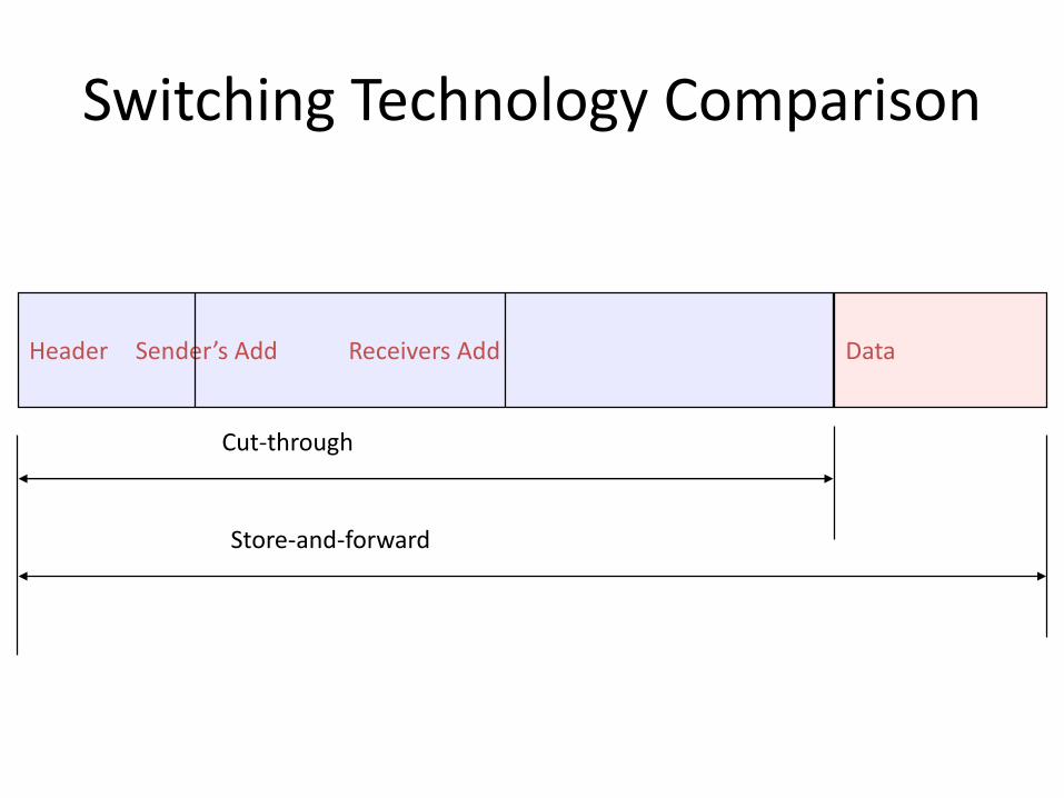
R
1A-23-F9-CD-06-9B222222222220
111111111110E6-E9-00-17-BB-4BCC-49-DE-D0-AB-7D
111111111112
111111111111
74-29-9C-E8-FF-55
A
222222222222
49-BD-D2-C7-56-2A
22222222222188-B2-2F-54-1A-0F
B
Addressing routing to another LAN
IP
Eth
Phy
frame sent from A to R
IP
Eth
Phy
frame received at R datagram removed passed up to IP
MAC src 74-29-9C-E8-FF-55
MAC dest E6-E9-00-17-BB-4B
IP src 111111111111
IP dest 222222222222
IP src 111111111111
IP dest 222222222222
R
1A-23-F9-CD-06-9B222222222220
111111111110E6-E9-00-17-BB-4BCC-49-DE-D0-AB-7D
111111111112
111111111111
74-29-9C-E8-FF-55
A
222222222222
49-BD-D2-C7-56-2A
22222222222188-B2-2F-54-1A-0F
B
Addressing routing to another LAN
IP src 111111111111
IP dest 222222222222
R forwards datagram with IP source A destination B
R creates link-layer frame with Bs MAC address as dest frame contains A-to-B IP datagram
MAC src 1A-23-F9-CD-06-9B
MAC dest 49-BD-D2-C7-56-2A
IP
Eth
Phy
IP
Eth
Phy
R
1A-23-F9-CD-06-9B222222222220
111111111110E6-E9-00-17-BB-4BCC-49-DE-D0-AB-7D
111111111112
111111111111
74-29-9C-E8-FF-55
A
222222222222
49-BD-D2-C7-56-2A
22222222222188-B2-2F-54-1A-0F
B
Addressing routing to another LAN R forwards datagram with IP source A destination B
R creates link-layer frame with Bs MAC address as dest frame contains A-to-B IP datagram
IP src 111111111111
IP dest 222222222222
MAC src 1A-23-F9-CD-06-9B
MAC dest 49-BD-D2-C7-56-2A
IP
Eth
Phy
IP
Eth
Phy
R
1A-23-F9-CD-06-9B222222222220
111111111110E6-E9-00-17-BB-4BCC-49-DE-D0-AB-7D
111111111112
111111111111
74-29-9C-E8-FF-55
A
222222222222
49-BD-D2-C7-56-2A
22222222222188-B2-2F-54-1A-0F
B
Addressing routing to another LAN R forwards datagram with IP source A destination B
R creates link-layer frame with Bs MAC address as dest frame contains A-to-B IP datagram
IP src 111111111111
IP dest 222222222222
MAC src 1A-23-F9-CD-06-9B
MAC dest 49-BD-D2-C7-56-2A
IP
Eth
Phy
Ethernet
ldquodominantrdquo wired LAN technology
bull cheap $20 for NIC
bull first widely used LAN technology
bull simpler cheaper than token LANs and ATM
bull kept up with speed race 10 Mbps ndash 10 Gbps
Metcalfersquos Ethernet sketch
Ethernet physical topology
bull bus popular through mid 90sndash all nodes in same collision domain (can collide with
each other)
bull star prevails todayndash active switch in center
ndash each ldquospokerdquo runs a (separate) Ethernet protocol (nodes do not collide with each other)
switch
bus coaxial cablestar
Ethernet frame structure
sending adapter encapsulates IP datagram (or other network layer protocol packet) in Ethernet frame
preamble
7 bytes with pattern 10101010 followed by one byte with pattern 10101011
used to synchronize receiver sender clock rates
destaddress
sourceaddress
data (payload) CRCpreamble
type
Ethernet frame structure (more)
addresses 6 byte source destination MAC addresses
if adapter receives frame with matching destination address or with broadcast address (eg ARP packet) it passes data in frame to network layer protocol
otherwise adapter discards frame
type indicates higher layer protocol (mostly IP but others possible eg Novell IPX AppleTalk)
CRC cyclic redundancy check at receiver
error detected frame is dropped
destaddress
sourceaddress
data (payload) CRCpreamble
type
Ethernet unreliable connectionless
bull connectionless no handshaking between sending and receiving NICs
bull unreliable receiving NIC doesnt send acks or nacks to sending NIC
ndash data in dropped frames recovered only if initial sender uses higher layer rdt (eg TCP) otherwise dropped data lost
Switch multiple simultaneous transmissions
bull hosts have dedicated direct connection to switch
bull switches buffer packets
bull Ethernet protocol used on eachincoming link but no collisions full duplex
ndash each link is its own collision domain
bull switching A-to-Arsquo and B-to-Brsquocan transmit simultaneously without collisions switch with six interfaces
(123456)
A
Arsquo
B
Brsquo C
Crsquo
1 2
345
6
Switch forwarding table
Q how does switch know Arsquo reachable via interface 4 Brsquo reachable via interface 5
switch with six interfaces
(123456)
A
Arsquo
B
Brsquo C
Crsquo
1 2
345
6 A each switch has a switch table each entry
(MAC address of host
interface to reach host time
stamp)
looks like a routing table
Q how are entries created maintained in switch table
something like a routing protocol
A
Arsquo
B
Brsquo C
Crsquo
1 2
345
6
Switch self-learning
bull switch learns which hosts can be reached through which interfaces
ndash when frame received switch ldquolearnsrdquo location of sender incoming LAN segment
ndash records senderlocation pair in switch table
A Arsquo
Source A
Dest Arsquo
MAC addr interface TTL
Switch table
(initially empty)A 1 60
A
Arsquo
B
Brsquo C
Crsquo
1 2
345
6
Self-learning forwarding example
A Arsquo
Source A
Dest Arsquo
MAC addr interface TTL
switch table
(initially empty)A 1 60
A ArsquoA ArsquoA ArsquoA ArsquoA Arsquo
bull frame destination Arsquo locaton unknownflood
Arsquo A
destination A location
known
Arsquo 4 60
selectively send
on just one link
Interconnecting switches
switches can be connected together
Q sending from A to G - how does S1 know to forward frame destined to F via S4 and S3
A self learning (works exactly the same as in single-switch case)
A
B
S1
C D
E
F
S2
S4
S3
H
I
G
Self-learning multi-switch example
Suppose C sends frame to I I responds to C
Q show switch tables and packet forwarding in S1 S2 S3 S4
A
B
S1
C D
E
F
S2
S4
S3
H
I
G
Switches vs routers
both are store-and-forward
routers network-layer devices (examine network-layer headers)
switches link-layer devices (examine link-layer headers)
both have forwarding tables routers compute tables
using routing algorithms IP addresses
switches learn forwarding table using flooding learning MAC addresses
application
transport
network
link
physical
network
link
physical
link
physical
switch
datagram
application
transport
network
link
physical
frame
frame
frame
datagram
VLANs motivation
consider CS user moves office to EE
but wants connect to CS switch
single broadcast domain
all layer-2 broadcast traffic (ARP DHCP unknown location of destination MAC address) must cross entire LAN
securityprivacy efficiency issues
Computer
Science Electrical
Engineering
Computer
Engineering
VLANsport-based VLAN switch ports
grouped (by switch management software) so that single physical switch helliphellip
switch(es) supporting
VLAN capabilities can
be configured to
define multiple virtual
LANS over single
physical LAN
infrastructure
Virtual Local
Area Network1
8
9
16102
7
hellip
Electrical Engineering
(VLAN ports 1-8)
Computer Science
(VLAN ports 9-15)
15
hellip
Electrical Engineering
(VLAN ports 1-8)
hellip
1
82
7 9
1610
15
hellip
Computer Science
(VLAN ports 9-16)
hellip operates as multiple virtual switches
Port-based VLAN
1
8
9
16102
7
hellip
Electrical Engineering
(VLAN ports 1-8)
Computer Science
(VLAN ports 9-15)
15
hellip
traffic isolation frames tofrom ports 1-8 can onlyreach ports 1-8 can also define VLAN based on
MAC addresses of endpoints rather than switch port
dynamic membershipports can be dynamically assigned among VLANs
router
forwarding between VLANSdone via routing (just as with separate switches) in practice vendors sell combined
switches plus routers
R
1A-23-F9-CD-06-9B222222222220
111111111110E6-E9-00-17-BB-4BCC-49-DE-D0-AB-7D
111111111112
111111111111
74-29-9C-E8-FF-55
A
222222222222
49-BD-D2-C7-56-2A
22222222222188-B2-2F-54-1A-0F
B
Addressing routing to another LAN
IP src 111111111111
IP dest 222222222222
R forwards datagram with IP source A destination B
R creates link-layer frame with Bs MAC address as dest frame contains A-to-B IP datagram
MAC src 1A-23-F9-CD-06-9B
MAC dest 49-BD-D2-C7-56-2A
IP
Eth
Phy
IP
Eth
Phy
R
1A-23-F9-CD-06-9B222222222220
111111111110E6-E9-00-17-BB-4BCC-49-DE-D0-AB-7D
111111111112
111111111111
74-29-9C-E8-FF-55
A
222222222222
49-BD-D2-C7-56-2A
22222222222188-B2-2F-54-1A-0F
B
Addressing routing to another LAN R forwards datagram with IP source A destination B
R creates link-layer frame with Bs MAC address as dest frame contains A-to-B IP datagram
IP src 111111111111
IP dest 222222222222
MAC src 1A-23-F9-CD-06-9B
MAC dest 49-BD-D2-C7-56-2A
IP
Eth
Phy
IP
Eth
Phy
R
1A-23-F9-CD-06-9B222222222220
111111111110E6-E9-00-17-BB-4BCC-49-DE-D0-AB-7D
111111111112
111111111111
74-29-9C-E8-FF-55
A
222222222222
49-BD-D2-C7-56-2A
22222222222188-B2-2F-54-1A-0F
B
Addressing routing to another LAN R forwards datagram with IP source A destination B
R creates link-layer frame with Bs MAC address as dest frame contains A-to-B IP datagram
IP src 111111111111
IP dest 222222222222
MAC src 1A-23-F9-CD-06-9B
MAC dest 49-BD-D2-C7-56-2A
IP
Eth
Phy
Ethernet
ldquodominantrdquo wired LAN technology
bull cheap $20 for NIC
bull first widely used LAN technology
bull simpler cheaper than token LANs and ATM
bull kept up with speed race 10 Mbps ndash 10 Gbps
Metcalfersquos Ethernet sketch
Ethernet physical topology
bull bus popular through mid 90sndash all nodes in same collision domain (can collide with
each other)
bull star prevails todayndash active switch in center
ndash each ldquospokerdquo runs a (separate) Ethernet protocol (nodes do not collide with each other)
switch
bus coaxial cablestar
Ethernet frame structure
sending adapter encapsulates IP datagram (or other network layer protocol packet) in Ethernet frame
preamble
7 bytes with pattern 10101010 followed by one byte with pattern 10101011
used to synchronize receiver sender clock rates
destaddress
sourceaddress
data (payload) CRCpreamble
type
Ethernet frame structure (more)
addresses 6 byte source destination MAC addresses
if adapter receives frame with matching destination address or with broadcast address (eg ARP packet) it passes data in frame to network layer protocol
otherwise adapter discards frame
type indicates higher layer protocol (mostly IP but others possible eg Novell IPX AppleTalk)
CRC cyclic redundancy check at receiver
error detected frame is dropped
destaddress
sourceaddress
data (payload) CRCpreamble
type
Ethernet unreliable connectionless
bull connectionless no handshaking between sending and receiving NICs
bull unreliable receiving NIC doesnt send acks or nacks to sending NIC
ndash data in dropped frames recovered only if initial sender uses higher layer rdt (eg TCP) otherwise dropped data lost
Switch multiple simultaneous transmissions
bull hosts have dedicated direct connection to switch
bull switches buffer packets
bull Ethernet protocol used on eachincoming link but no collisions full duplex
ndash each link is its own collision domain
bull switching A-to-Arsquo and B-to-Brsquocan transmit simultaneously without collisions switch with six interfaces
(123456)
A
Arsquo
B
Brsquo C
Crsquo
1 2
345
6
Switch forwarding table
Q how does switch know Arsquo reachable via interface 4 Brsquo reachable via interface 5
switch with six interfaces
(123456)
A
Arsquo
B
Brsquo C
Crsquo
1 2
345
6 A each switch has a switch table each entry
(MAC address of host
interface to reach host time
stamp)
looks like a routing table
Q how are entries created maintained in switch table
something like a routing protocol
A
Arsquo
B
Brsquo C
Crsquo
1 2
345
6
Switch self-learning
bull switch learns which hosts can be reached through which interfaces
ndash when frame received switch ldquolearnsrdquo location of sender incoming LAN segment
ndash records senderlocation pair in switch table
A Arsquo
Source A
Dest Arsquo
MAC addr interface TTL
Switch table
(initially empty)A 1 60
A
Arsquo
B
Brsquo C
Crsquo
1 2
345
6
Self-learning forwarding example
A Arsquo
Source A
Dest Arsquo
MAC addr interface TTL
switch table
(initially empty)A 1 60
A ArsquoA ArsquoA ArsquoA ArsquoA Arsquo
bull frame destination Arsquo locaton unknownflood
Arsquo A
destination A location
known
Arsquo 4 60
selectively send
on just one link
Interconnecting switches
switches can be connected together
Q sending from A to G - how does S1 know to forward frame destined to F via S4 and S3
A self learning (works exactly the same as in single-switch case)
A
B
S1
C D
E
F
S2
S4
S3
H
I
G
Self-learning multi-switch example
Suppose C sends frame to I I responds to C
Q show switch tables and packet forwarding in S1 S2 S3 S4
A
B
S1
C D
E
F
S2
S4
S3
H
I
G
Switches vs routers
both are store-and-forward
routers network-layer devices (examine network-layer headers)
switches link-layer devices (examine link-layer headers)
both have forwarding tables routers compute tables
using routing algorithms IP addresses
switches learn forwarding table using flooding learning MAC addresses
application
transport
network
link
physical
network
link
physical
link
physical
switch
datagram
application
transport
network
link
physical
frame
frame
frame
datagram
VLANs motivation
consider CS user moves office to EE
but wants connect to CS switch
single broadcast domain
all layer-2 broadcast traffic (ARP DHCP unknown location of destination MAC address) must cross entire LAN
securityprivacy efficiency issues
Computer
Science Electrical
Engineering
Computer
Engineering
VLANsport-based VLAN switch ports
grouped (by switch management software) so that single physical switch helliphellip
switch(es) supporting
VLAN capabilities can
be configured to
define multiple virtual
LANS over single
physical LAN
infrastructure
Virtual Local
Area Network1
8
9
16102
7
hellip
Electrical Engineering
(VLAN ports 1-8)
Computer Science
(VLAN ports 9-15)
15
hellip
Electrical Engineering
(VLAN ports 1-8)
hellip
1
82
7 9
1610
15
hellip
Computer Science
(VLAN ports 9-16)
hellip operates as multiple virtual switches
Port-based VLAN
1
8
9
16102
7
hellip
Electrical Engineering
(VLAN ports 1-8)
Computer Science
(VLAN ports 9-15)
15
hellip
traffic isolation frames tofrom ports 1-8 can onlyreach ports 1-8 can also define VLAN based on
MAC addresses of endpoints rather than switch port
dynamic membershipports can be dynamically assigned among VLANs
router
forwarding between VLANSdone via routing (just as with separate switches) in practice vendors sell combined
switches plus routers

R
1A-23-F9-CD-06-9B222222222220
111111111110E6-E9-00-17-BB-4BCC-49-DE-D0-AB-7D
111111111112
111111111111
74-29-9C-E8-FF-55
A
222222222222
49-BD-D2-C7-56-2A
22222222222188-B2-2F-54-1A-0F
B
Addressing routing to another LAN R forwards datagram with IP source A destination B
R creates link-layer frame with Bs MAC address as dest frame contains A-to-B IP datagram
IP src 111111111111
IP dest 222222222222
MAC src 1A-23-F9-CD-06-9B
MAC dest 49-BD-D2-C7-56-2A
IP
Eth
Phy
IP
Eth
Phy
R
1A-23-F9-CD-06-9B222222222220
111111111110E6-E9-00-17-BB-4BCC-49-DE-D0-AB-7D
111111111112
111111111111
74-29-9C-E8-FF-55
A
222222222222
49-BD-D2-C7-56-2A
22222222222188-B2-2F-54-1A-0F
B
Addressing routing to another LAN R forwards datagram with IP source A destination B
R creates link-layer frame with Bs MAC address as dest frame contains A-to-B IP datagram
IP src 111111111111
IP dest 222222222222
MAC src 1A-23-F9-CD-06-9B
MAC dest 49-BD-D2-C7-56-2A
IP
Eth
Phy
Ethernet
ldquodominantrdquo wired LAN technology
bull cheap $20 for NIC
bull first widely used LAN technology
bull simpler cheaper than token LANs and ATM
bull kept up with speed race 10 Mbps ndash 10 Gbps
Metcalfersquos Ethernet sketch
Ethernet physical topology
bull bus popular through mid 90sndash all nodes in same collision domain (can collide with
each other)
bull star prevails todayndash active switch in center
ndash each ldquospokerdquo runs a (separate) Ethernet protocol (nodes do not collide with each other)
switch
bus coaxial cablestar
Ethernet frame structure
sending adapter encapsulates IP datagram (or other network layer protocol packet) in Ethernet frame
preamble
7 bytes with pattern 10101010 followed by one byte with pattern 10101011
used to synchronize receiver sender clock rates
destaddress
sourceaddress
data (payload) CRCpreamble
type
Ethernet frame structure (more)
addresses 6 byte source destination MAC addresses
if adapter receives frame with matching destination address or with broadcast address (eg ARP packet) it passes data in frame to network layer protocol
otherwise adapter discards frame
type indicates higher layer protocol (mostly IP but others possible eg Novell IPX AppleTalk)
CRC cyclic redundancy check at receiver
error detected frame is dropped
destaddress
sourceaddress
data (payload) CRCpreamble
type
Ethernet unreliable connectionless
bull connectionless no handshaking between sending and receiving NICs
bull unreliable receiving NIC doesnt send acks or nacks to sending NIC
ndash data in dropped frames recovered only if initial sender uses higher layer rdt (eg TCP) otherwise dropped data lost
Switch multiple simultaneous transmissions
bull hosts have dedicated direct connection to switch
bull switches buffer packets
bull Ethernet protocol used on eachincoming link but no collisions full duplex
ndash each link is its own collision domain
bull switching A-to-Arsquo and B-to-Brsquocan transmit simultaneously without collisions switch with six interfaces
(123456)
A
Arsquo
B
Brsquo C
Crsquo
1 2
345
6
Switch forwarding table
Q how does switch know Arsquo reachable via interface 4 Brsquo reachable via interface 5
switch with six interfaces
(123456)
A
Arsquo
B
Brsquo C
Crsquo
1 2
345
6 A each switch has a switch table each entry
(MAC address of host
interface to reach host time
stamp)
looks like a routing table
Q how are entries created maintained in switch table
something like a routing protocol
A
Arsquo
B
Brsquo C
Crsquo
1 2
345
6
Switch self-learning
bull switch learns which hosts can be reached through which interfaces
ndash when frame received switch ldquolearnsrdquo location of sender incoming LAN segment
ndash records senderlocation pair in switch table
A Arsquo
Source A
Dest Arsquo
MAC addr interface TTL
Switch table
(initially empty)A 1 60
A
Arsquo
B
Brsquo C
Crsquo
1 2
345
6
Self-learning forwarding example
A Arsquo
Source A
Dest Arsquo
MAC addr interface TTL
switch table
(initially empty)A 1 60
A ArsquoA ArsquoA ArsquoA ArsquoA Arsquo
bull frame destination Arsquo locaton unknownflood
Arsquo A
destination A location
known
Arsquo 4 60
selectively send
on just one link
Interconnecting switches
switches can be connected together
Q sending from A to G - how does S1 know to forward frame destined to F via S4 and S3
A self learning (works exactly the same as in single-switch case)
A
B
S1
C D
E
F
S2
S4
S3
H
I
G
Self-learning multi-switch example
Suppose C sends frame to I I responds to C
Q show switch tables and packet forwarding in S1 S2 S3 S4
A
B
S1
C D
E
F
S2
S4
S3
H
I
G
Switches vs routers
both are store-and-forward
routers network-layer devices (examine network-layer headers)
switches link-layer devices (examine link-layer headers)
both have forwarding tables routers compute tables
using routing algorithms IP addresses
switches learn forwarding table using flooding learning MAC addresses
application
transport
network
link
physical
network
link
physical
link
physical
switch
datagram
application
transport
network
link
physical
frame
frame
frame
datagram
VLANs motivation
consider CS user moves office to EE
but wants connect to CS switch
single broadcast domain
all layer-2 broadcast traffic (ARP DHCP unknown location of destination MAC address) must cross entire LAN
securityprivacy efficiency issues
Computer
Science Electrical
Engineering
Computer
Engineering
VLANsport-based VLAN switch ports
grouped (by switch management software) so that single physical switch helliphellip
switch(es) supporting
VLAN capabilities can
be configured to
define multiple virtual
LANS over single
physical LAN
infrastructure
Virtual Local
Area Network1
8
9
16102
7
hellip
Electrical Engineering
(VLAN ports 1-8)
Computer Science
(VLAN ports 9-15)
15
hellip
Electrical Engineering
(VLAN ports 1-8)
hellip
1
82
7 9
1610
15
hellip
Computer Science
(VLAN ports 9-16)
hellip operates as multiple virtual switches
Port-based VLAN
1
8
9
16102
7
hellip
Electrical Engineering
(VLAN ports 1-8)
Computer Science
(VLAN ports 9-15)
15
hellip
traffic isolation frames tofrom ports 1-8 can onlyreach ports 1-8 can also define VLAN based on
MAC addresses of endpoints rather than switch port
dynamic membershipports can be dynamically assigned among VLANs
router
forwarding between VLANSdone via routing (just as with separate switches) in practice vendors sell combined
switches plus routers

R
1A-23-F9-CD-06-9B222222222220
111111111110E6-E9-00-17-BB-4BCC-49-DE-D0-AB-7D
111111111112
111111111111
74-29-9C-E8-FF-55
A
222222222222
49-BD-D2-C7-56-2A
22222222222188-B2-2F-54-1A-0F
B
Addressing routing to another LAN R forwards datagram with IP source A destination B
R creates link-layer frame with Bs MAC address as dest frame contains A-to-B IP datagram
IP src 111111111111
IP dest 222222222222
MAC src 1A-23-F9-CD-06-9B
MAC dest 49-BD-D2-C7-56-2A
IP
Eth
Phy
Ethernet
ldquodominantrdquo wired LAN technology
bull cheap $20 for NIC
bull first widely used LAN technology
bull simpler cheaper than token LANs and ATM
bull kept up with speed race 10 Mbps ndash 10 Gbps
Metcalfersquos Ethernet sketch
Ethernet physical topology
bull bus popular through mid 90sndash all nodes in same collision domain (can collide with
each other)
bull star prevails todayndash active switch in center
ndash each ldquospokerdquo runs a (separate) Ethernet protocol (nodes do not collide with each other)
switch
bus coaxial cablestar
Ethernet frame structure
sending adapter encapsulates IP datagram (or other network layer protocol packet) in Ethernet frame
preamble
7 bytes with pattern 10101010 followed by one byte with pattern 10101011
used to synchronize receiver sender clock rates
destaddress
sourceaddress
data (payload) CRCpreamble
type
Ethernet frame structure (more)
addresses 6 byte source destination MAC addresses
if adapter receives frame with matching destination address or with broadcast address (eg ARP packet) it passes data in frame to network layer protocol
otherwise adapter discards frame
type indicates higher layer protocol (mostly IP but others possible eg Novell IPX AppleTalk)
CRC cyclic redundancy check at receiver
error detected frame is dropped
destaddress
sourceaddress
data (payload) CRCpreamble
type
Ethernet unreliable connectionless
bull connectionless no handshaking between sending and receiving NICs
bull unreliable receiving NIC doesnt send acks or nacks to sending NIC
ndash data in dropped frames recovered only if initial sender uses higher layer rdt (eg TCP) otherwise dropped data lost
Switch multiple simultaneous transmissions
bull hosts have dedicated direct connection to switch
bull switches buffer packets
bull Ethernet protocol used on eachincoming link but no collisions full duplex
ndash each link is its own collision domain
bull switching A-to-Arsquo and B-to-Brsquocan transmit simultaneously without collisions switch with six interfaces
(123456)
A
Arsquo
B
Brsquo C
Crsquo
1 2
345
6
Switch forwarding table
Q how does switch know Arsquo reachable via interface 4 Brsquo reachable via interface 5
switch with six interfaces
(123456)
A
Arsquo
B
Brsquo C
Crsquo
1 2
345
6 A each switch has a switch table each entry
(MAC address of host
interface to reach host time
stamp)
looks like a routing table
Q how are entries created maintained in switch table
something like a routing protocol
A
Arsquo
B
Brsquo C
Crsquo
1 2
345
6
Switch self-learning
bull switch learns which hosts can be reached through which interfaces
ndash when frame received switch ldquolearnsrdquo location of sender incoming LAN segment
ndash records senderlocation pair in switch table
A Arsquo
Source A
Dest Arsquo
MAC addr interface TTL
Switch table
(initially empty)A 1 60
A
Arsquo
B
Brsquo C
Crsquo
1 2
345
6
Self-learning forwarding example
A Arsquo
Source A
Dest Arsquo
MAC addr interface TTL
switch table
(initially empty)A 1 60
A ArsquoA ArsquoA ArsquoA ArsquoA Arsquo
bull frame destination Arsquo locaton unknownflood
Arsquo A
destination A location
known
Arsquo 4 60
selectively send
on just one link
Interconnecting switches
switches can be connected together
Q sending from A to G - how does S1 know to forward frame destined to F via S4 and S3
A self learning (works exactly the same as in single-switch case)
A
B
S1
C D
E
F
S2
S4
S3
H
I
G
Self-learning multi-switch example
Suppose C sends frame to I I responds to C
Q show switch tables and packet forwarding in S1 S2 S3 S4
A
B
S1
C D
E
F
S2
S4
S3
H
I
G
Switches vs routers
both are store-and-forward
routers network-layer devices (examine network-layer headers)
switches link-layer devices (examine link-layer headers)
both have forwarding tables routers compute tables
using routing algorithms IP addresses
switches learn forwarding table using flooding learning MAC addresses
application
transport
network
link
physical
network
link
physical
link
physical
switch
datagram
application
transport
network
link
physical
frame
frame
frame
datagram
VLANs motivation
consider CS user moves office to EE
but wants connect to CS switch
single broadcast domain
all layer-2 broadcast traffic (ARP DHCP unknown location of destination MAC address) must cross entire LAN
securityprivacy efficiency issues
Computer
Science Electrical
Engineering
Computer
Engineering
VLANsport-based VLAN switch ports
grouped (by switch management software) so that single physical switch helliphellip
switch(es) supporting
VLAN capabilities can
be configured to
define multiple virtual
LANS over single
physical LAN
infrastructure
Virtual Local
Area Network1
8
9
16102
7
hellip
Electrical Engineering
(VLAN ports 1-8)
Computer Science
(VLAN ports 9-15)
15
hellip
Electrical Engineering
(VLAN ports 1-8)
hellip
1
82
7 9
1610
15
hellip
Computer Science
(VLAN ports 9-16)
hellip operates as multiple virtual switches
Port-based VLAN
1
8
9
16102
7
hellip
Electrical Engineering
(VLAN ports 1-8)
Computer Science
(VLAN ports 9-15)
15
hellip
traffic isolation frames tofrom ports 1-8 can onlyreach ports 1-8 can also define VLAN based on
MAC addresses of endpoints rather than switch port
dynamic membershipports can be dynamically assigned among VLANs
router
forwarding between VLANSdone via routing (just as with separate switches) in practice vendors sell combined
switches plus routers
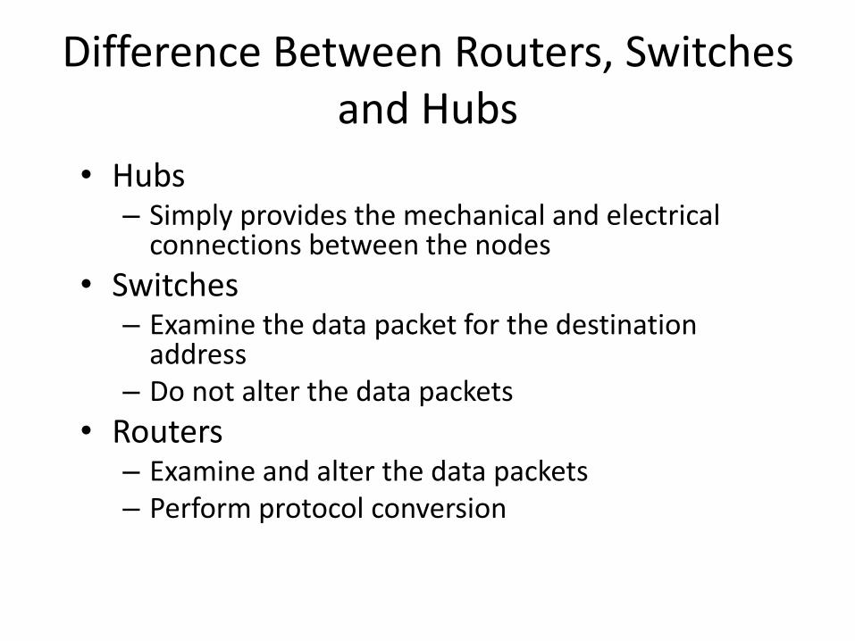
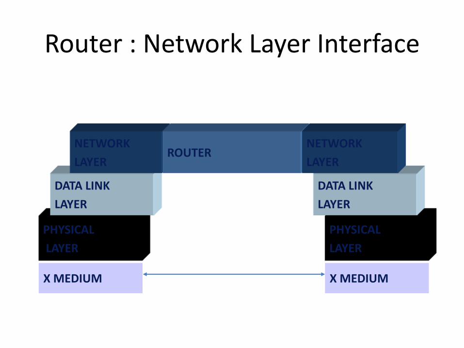

A
Arsquo
B
Brsquo C
Crsquo
1 2
345
6
Self-learning forwarding example
A Arsquo
Source A
Dest Arsquo
MAC addr interface TTL
switch table
(initially empty)A 1 60
A ArsquoA ArsquoA ArsquoA ArsquoA Arsquo
bull frame destination Arsquo locaton unknownflood
Arsquo A
destination A location
known
Arsquo 4 60
selectively send
on just one link
Interconnecting switches
switches can be connected together
Q sending from A to G - how does S1 know to forward frame destined to F via S4 and S3
A self learning (works exactly the same as in single-switch case)
A
B
S1
C D
E
F
S2
S4
S3
H
I
G
Self-learning multi-switch example
Suppose C sends frame to I I responds to C
Q show switch tables and packet forwarding in S1 S2 S3 S4
A
B
S1
C D
E
F
S2
S4
S3
H
I
G
Switches vs routers
both are store-and-forward
routers network-layer devices (examine network-layer headers)
switches link-layer devices (examine link-layer headers)
both have forwarding tables routers compute tables
using routing algorithms IP addresses
switches learn forwarding table using flooding learning MAC addresses
application
transport
network
link
physical
network
link
physical
link
physical
switch
datagram
application
transport
network
link
physical
frame
frame
frame
datagram
VLANs motivation
consider CS user moves office to EE
but wants connect to CS switch
single broadcast domain
all layer-2 broadcast traffic (ARP DHCP unknown location of destination MAC address) must cross entire LAN
securityprivacy efficiency issues
Computer
Science Electrical
Engineering
Computer
Engineering
VLANsport-based VLAN switch ports
grouped (by switch management software) so that single physical switch helliphellip
switch(es) supporting
VLAN capabilities can
be configured to
define multiple virtual
LANS over single
physical LAN
infrastructure
Virtual Local
Area Network1
8
9
16102
7
hellip
Electrical Engineering
(VLAN ports 1-8)
Computer Science
(VLAN ports 9-15)
15
hellip
Electrical Engineering
(VLAN ports 1-8)
hellip
1
82
7 9
1610
15
hellip
Computer Science
(VLAN ports 9-16)
hellip operates as multiple virtual switches
Port-based VLAN
1
8
9
16102
7
hellip
Electrical Engineering
(VLAN ports 1-8)
Computer Science
(VLAN ports 9-15)
15
hellip
traffic isolation frames tofrom ports 1-8 can onlyreach ports 1-8 can also define VLAN based on
MAC addresses of endpoints rather than switch port
dynamic membershipports can be dynamically assigned among VLANs
router
forwarding between VLANSdone via routing (just as with separate switches) in practice vendors sell combined
switches plus routers
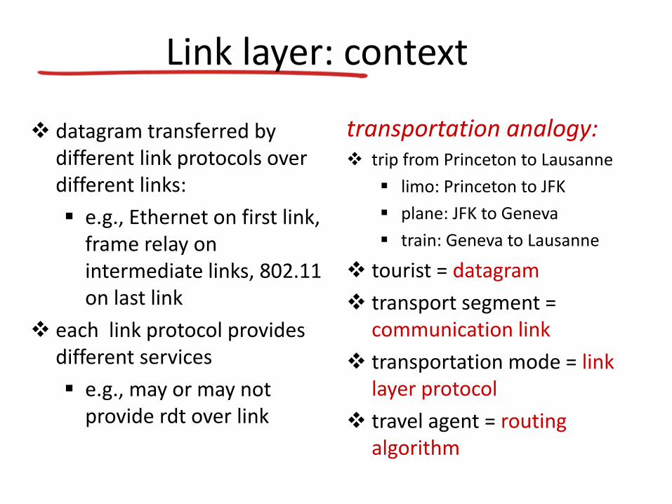
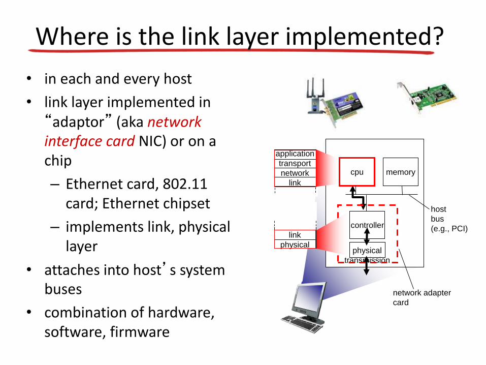
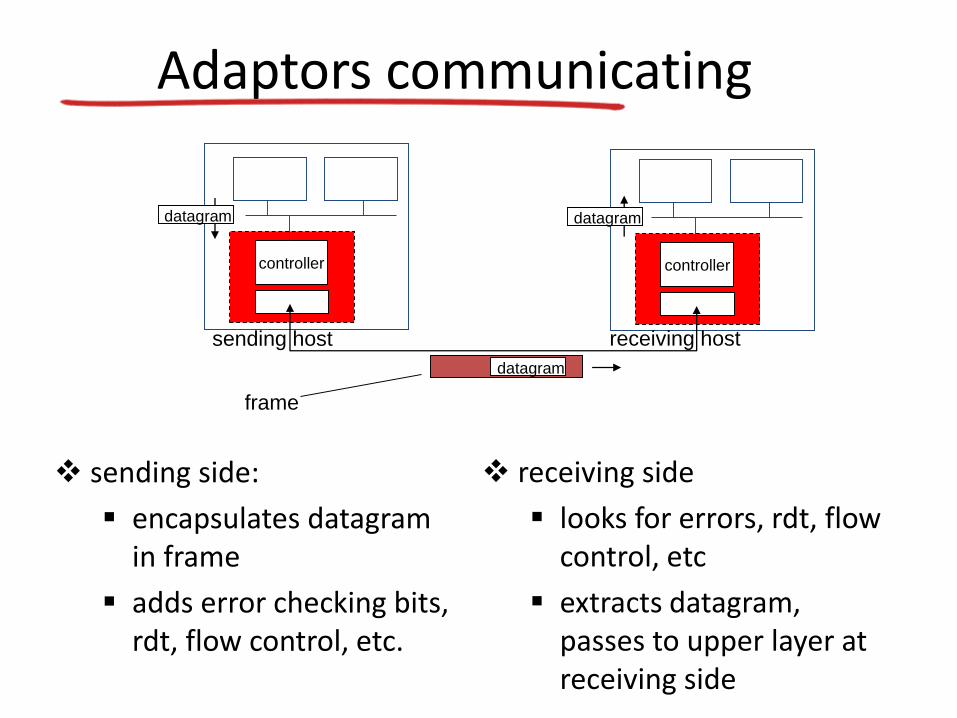