photon antibunching and bunching in a ring-resonator ...jushen/papers/rqed.pdf · photon...
TRANSCRIPT
Photon antibunching and bunching in aring-resonator waveguide quantumelectrodynamics systemZIHAO CHEN, YAO ZHOU, AND JUNG-TSUNG SHEN*Department of Electrical and System Engineering, Washington University in St. Louis, St. Louis, Missouri 63130, USA*Corresponding author: [email protected]
Received 25 May 2016; revised 21 June 2016; accepted 23 June 2016; posted 23 June 2016 (Doc. ID 267011); published 14 July 2016
We numerically investigate the photonic state generation andits nonclassical correlations in a ring-resonator waveguidequantum electrodynamics system. Specifically, we discussphoton antibunching and bunching in various scenarios,including the imperfect resonator with backscattering anddissipations. Our numerical results indicate that an imperfectring resonator with backscattering can enhance the quality ofantibunching. In addition, we also identify the quantumphotonic halo phenomenon in the photon scattering dynam-ics and the shoulder effect in the second-order correlationfunction. © 2016 Optical Society of America
OCIS codes: (270.4180) Multiphoton processes; (270.5290) Photon
statistics; (230.4555) Coupled resonators.
http://dx.doi.org/10.1364/OL.41.003313
First observed in the resonance fluorescence of sodium atoms[1], photon antibunching manifests a genuine quantum corre-lation of sub-Poissonian photon statistics. Photon antibunch-ing is a key requirement in many applications for quantuminformation science. In recent years, much attention has beendevoted to generations of photon antibunching in solid-stateplatforms. For instance, molecules [2] and quantum dots[3–7] have been demonstrated to generate photon antibunch-ing. These solid-state realizations are especially promising foron-chip quantum communication. The generations of quantumphotonic states in cavity quantum electrodynamics (cQED) sys-tems have been theoretically studied before, using, for example,the master-equation approach [8–13]. Recently, due to the ad-vent of coherent control techniques, the photonic wavefunctioninformation can be directly probed. Subsequently, approachesbased on real space dynamics have been developed to investigatecQED systems [14–16]. To date, although the system of a ringresonator (whispering-gallery-mode resonator) has been exper-imentally realized [17,18], the detailed numerical investigationhas yet to be carried out. In this Letter, we provide a detailednumerical investigation for this case.
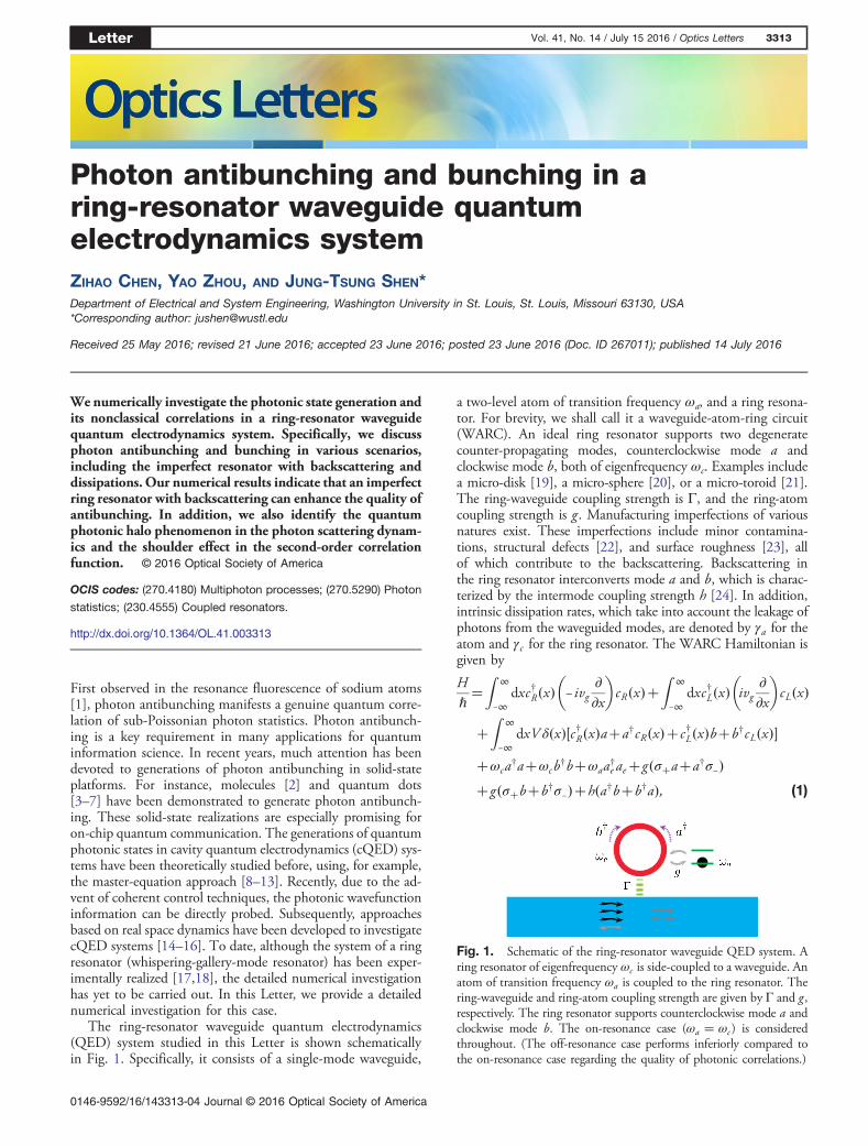
The ring-resonator waveguide quantum electrodynamics(QED) system studied in this Letter is shown schematicallyin Fig. 1. Specifically, it consists of a single-mode waveguide,
a two-level atom of transition frequency ωa, and a ring resona-tor. For brevity, we shall call it a waveguide-atom-ring circuit(WARC). An ideal ring resonator supports two degeneratecounter-propagating modes, counterclockwise mode a andclockwise mode b, both of eigenfrequency ωc. Examples includea micro-disk [19], a micro-sphere [20], or a micro-toroid [21].The ring-waveguide coupling strength is Γ, and the ring-atomcoupling strength is g . Manufacturing imperfections of variousnatures exist. These imperfections include minor contamina-tions, structural defects [22], and surface roughness [23], allof which contribute to the backscattering. Backscattering inthe ring resonator interconverts mode a and b, which is charac-terized by the intermode coupling strength h [24]. In addition,intrinsic dissipation rates, which take into account the leakage ofphotons from the waveguided modes, are denoted by γa for theatom and γc for the ring resonator. The WARC Hamiltonian isgiven by
Hℏ�Z
∞
−∞dxc†R�x�
�− ivg
∂∂x
�cR�x��
Z∞
−∞dxc†L�x�
�ivg
∂∂x
�cL�x�
�Z
∞
−∞dxV δ�x��c†R�x�a�a†cR�x��c†L�x�b�b†cL�x��
�ωca†a�ωcb†b�ωaa†e ae�g�σ�a�a†σ−��g�σ�b�b†σ−��h�a†b�b†a�; (1)
Fig. 1. Schematic of the ring-resonator waveguide QED system. Aring resonator of eigenfrequency ωc is side-coupled to a waveguide. Anatom of transition frequency ωa is coupled to the ring resonator. Thering-waveguide and ring-atom coupling strength are given by Γ and g ,respectively. The ring resonator supports counterclockwise mode a andclockwise mode b. The on-resonance case (ωa � ωc ) is consideredthroughout. (The off-resonance case performs inferiorly compared tothe on-resonance case regarding the quality of photonic correlations.)
Letter Vol. 41, No. 14 / July 15 2016 / Optics Letters 3313
0146-9592/16/143313-04 Journal © 2016 Optical Society of America
where Γ � V 2∕2vg , and the ground state of the atom has beenchosen as the energy reference point. c†�x� and c�x� denotethe creation and annihilation operators, which create a photonat spatial point x, with the subscripts R and L denoting theright- and left-moving photonic branches, respectively. a† and b†denote the creation operator in the ring resonator for mode a andmode b, respectively. σ� and σ− denote the raising and loweringoperator of the atomic transition, respectively. vg denotes thegroup velocity of the wave packet. In addition, the generaltwo-photon state is given by
j�t�i��Z
∞
−∞dx1dx2�ϕRR�x1;x2;t�
1ffiffiffi2
p c†R�x1�c†R�x2�
�ϕRL�x1;x2;t�1ffiffiffi2
p c†R�x1�c†L�x2�
�ϕLR�x1;x2;t�1ffiffiffi2
p c†L�x1�c†R�x2�
�ϕLL�x1;x2;t�1ffiffiffi2
p c†L�x1�c†L�x2��
�Z
∞
−∞dx�eRa�x;t�e−iωc t c†R�x�a†�eRb�x;t�e−iωc t c†R�x�b†�
�Z
∞
−∞dx�eLa�x;t�e−iωc t c†L�x�a†�eLb�x;t�e−iωc t c†L�x�b†�
�Z
∞
−∞dx�eRA�x;t�e−iωat c†R�x�σ�
�eLA�x;t�e−iωat c†L�x�σ��
�eaa�t�e−i2ωc t1ffiffiffi2
p a†a†�eab�t�e−i2ωc t a†b†
�ebb�t�e−i2ωc t1ffiffiffi2
p b†b†
�eaA�t�e−i�ωc�ωa�t a†σ��ebA�t�e−i�ωc�ωa�tb†σ��j0;−i;(2)
where j0; −i denotes the vacuum state. ϕ�x1; x2; t� denotes theprobability amplitude corresponding to the case where two pho-tons are in the waveguide. The subscript specifies the movingbranch of each photon. e�x; t� denotes the probability amplitudewhere one photon is in the waveguide branch (specified by thesubscript R or L, respectively), and the other is in the excited atom,the ring mode a, or mode b (specified by the subscript A, a, or b,respectively). e�t� denotes the probability amplitude correspond-ing to the case where both photons are not in the waveguide.
The information about two-photon correlations is encodedin the second-order correlation function: g �2��τ�. It has beenshown in Ref. [14] that a weak coherent state can yield the samesecond-order correlation function g�2��τ� as a two-photon Fockstate does. Here, we adopt the same approach by using a two-photon Fock state input from the left (i.e., initially ϕRR � ϕin)and evolve the system in time numerically. The scattered wavefunction is then recorded to compute numerically g�2��τ� todemonstrate photon antibunching and bunching [14].
The photon antibunching and bunching are the phenomenaof photon-photon correlation that go beyond the single-photon picture. Such an inter-photon correlation indicates aquantum nonlinearity at the level of individual photons [25].Nonetheless, an understanding of the single-photon dynamicsof the system could help to unveil the frequency range wherein
the two-photon correlation is significant. Specifically, each pho-ton in the two-photon wave packet operates at the frequencyidentified from the single-photon dynamics.
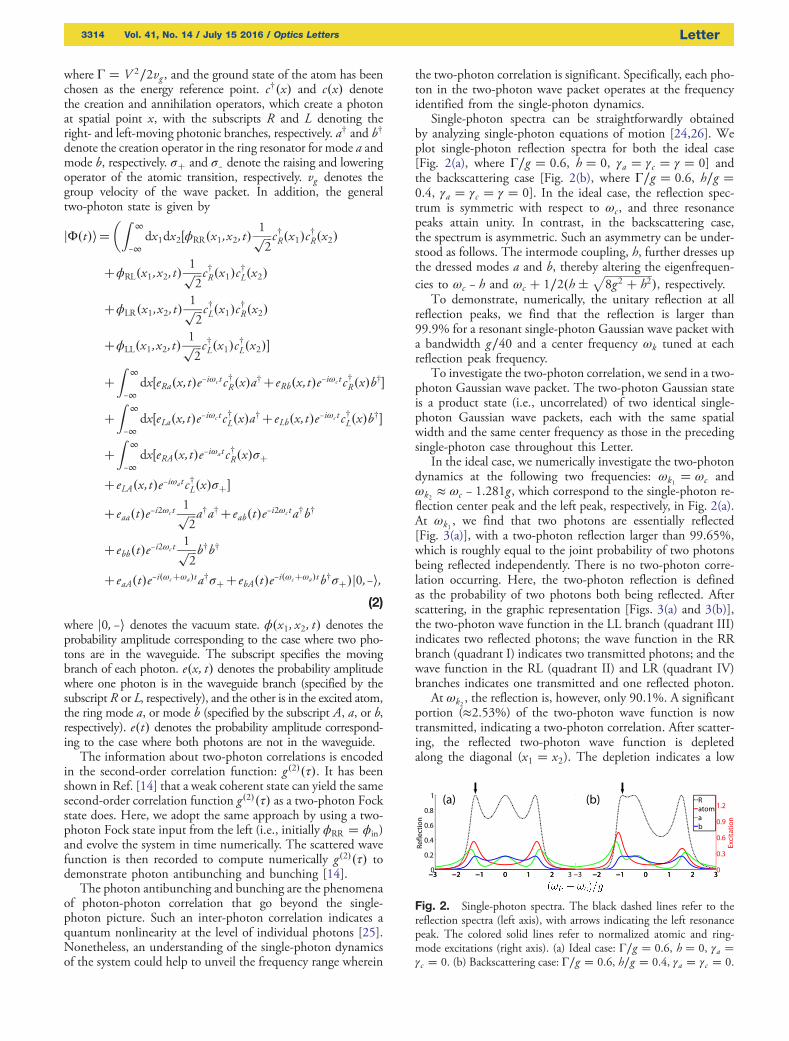
Single-photon spectra can be straightforwardly obtainedby analyzing single-photon equations of motion [24,26]. Weplot single-photon reflection spectra for both the ideal case[Fig. 2(a), where Γ∕g � 0.6, h � 0, γa � γc � γ � 0] andthe backscattering case [Fig. 2(b), where Γ∕g � 0.6, h∕g �0.4, γa � γc � γ � 0]. In the ideal case, the reflection spec-trum is symmetric with respect to ωc , and three resonancepeaks attain unity. In contrast, in the backscattering case,the spectrum is asymmetric. Such an asymmetry can be under-stood as follows. The intermode coupling, h, further dresses upthe dressed modes a and b, thereby altering the eigenfrequen-cies to ωc − h and ωc � 1∕2�h�
ffiffiffiffiffiffiffiffiffiffiffiffiffiffiffiffiffi8g2 � h2
p�, respectively.
To demonstrate, numerically, the unitary reflection at allreflection peaks, we find that the reflection is larger than99.9% for a resonant single-photon Gaussian wave packet witha bandwidth g∕40 and a center frequency ωk tuned at eachreflection peak frequency.
To investigate the two-photon correlation, we send in a two-photon Gaussian wave packet. The two-photon Gaussian stateis a product state (i.e., uncorrelated) of two identical single-photon Gaussian wave packets, each with the same spatialwidth and the same center frequency as those in the precedingsingle-photon case throughout this Letter.
In the ideal case, we numerically investigate the two-photondynamics at the following two frequencies: ωk1 � ωc andωk2 ≈ ωc − 1.281g , which correspond to the single-photon re-flection center peak and the left peak, respectively, in Fig. 2(a).At ωk1 , we find that two photons are essentially reflected[Fig. 3(a)], with a two-photon reflection larger than 99.65%,which is roughly equal to the joint probability of two photonsbeing reflected independently. There is no two-photon corre-lation occurring. Here, the two-photon reflection is definedas the probability of two photons both being reflected. Afterscattering, in the graphic representation [Figs. 3(a) and 3(b)],the two-photon wave function in the LL branch (quadrant III)indicates two reflected photons; the wave function in the RRbranch (quadrant I) indicates two transmitted photons; and thewave function in the RL (quadrant II) and LR (quadrant IV)branches indicates one transmitted and one reflected photon.
At ωk2 , the reflection is, however, only 90.1%. A significantportion (≈2.53%) of the two-photon wave function is nowtransmitted, indicating a two-photon correlation. After scatter-ing, the reflected two-photon wave function is depletedalong the diagonal (x1 � x2). The depletion indicates a low
Fig. 2. Single-photon spectra. The black dashed lines refer to thereflection spectra (left axis), with arrows indicating the left resonancepeak. The colored solid lines refer to normalized atomic and ring-mode excitations (right axis). (a) Ideal case: Γ∕g � 0.6, h � 0, γa �γc � 0. (b) Backscattering case: Γ∕g � 0.6, h∕g � 0.4, γa � γc � 0.
3314 Vol. 41, No. 14 / July 15 2016 / Optics Letters Letter
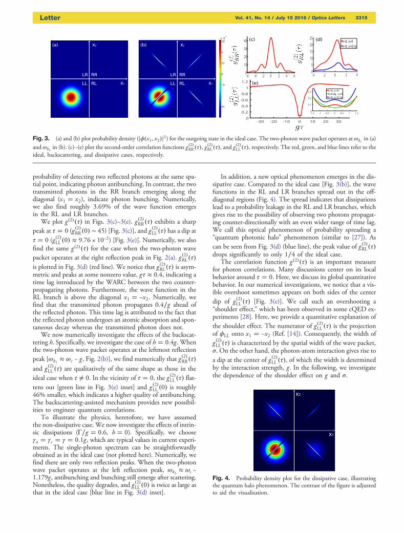
probability of detecting two reflected photons at the same spa-tial point, indicating photon antibunching. In contrast, the twotransmitted photons in the RR branch emerging along thediagonal (x1 � x2), indicate photon bunching. Numerically,we also find roughly 3.69% of the wave function emergesin the RL and LR branches.
We plot g �2��τ� in Figs. 3(c)–3(e). g �2�RR�τ� exhibits a sharppeak at τ � 0 (g �2�RR�0� ∼ 45) [Fig. 3(c)], and g �2�LL �τ� has a dip atτ � 0 (g�2�LL �0� ≈ 9.76 × 10⁻²) [Fig. 3(e)]. Numerically, we alsofind the same g�2��τ� for the case when the two-photon wavepacket operates at the right reflection peak in Fig. 2(a). g �2�RL�τ�is plotted in Fig. 3(d) (red line). We notice that g �2�RL�τ� is asym-metric and peaks at some nonzero value, gτ ≈ 0.4, indicating atime lag introduced by the WARC between the two counter-propagating photons. Furthermore, the wave function in theRL branch is above the diagonal x1 � −x2. Numerically, wefind that the transmitted photon propagates 0.4∕g ahead ofthe reflected photon. This time lag is attributed to the fact thatthe reflected photon undergoes an atomic absorption and spon-taneous decay whereas the transmitted photon does not.
We now numerically investigate the effects of the backscat-tering h. Specifically, we investigate the case of h � 0.4g. Whenthe two-photon wave packet operates at the leftmost reflectionpeak [ωk2 ≈ ωc − g , Fig. 2(b)], we find numerically that g �2�RR�τ�and g�2�LL �τ� are qualitatively of the same shape as those in theideal case when τ ≠ 0. In the vicinity of τ � 0, the g �2�LL �τ� flat-tens out [green line in Fig. 3(e) inset] and g �2�LL �0� is roughly46% smaller, which indicates a higher quality of antibunching.The backscattering-assisted mechanism provides new possibil-ities to engineer quantum correlations.
To illustrate the physics, heretofore, we have assumedthe non-dissipative case. We now investigate the effects of intrin-sic dissipations (Γ∕g � 0.6, h � 0). Specifically, we chooseγa � γc � γ � 0.1g , which are typical values in current experi-ments. The single-photon spectrum can be straightforwardlyobtained as in the ideal case (not plotted here). Numerically, wefind there are only two reflection peaks. When the two-photonwave packet operates at the left reflection peak, ωk3 ≈ ωc −1.179g , antibunching and bunching still emerge after scattering.Nonetheless, the quality degrades, and g �2�LL �0� is twice as large asthat in the ideal case [blue line in Fig. 3(d) inset].
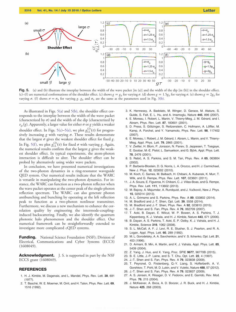
In addition, a new optical phenomenon emerges in the dis-sipative case. Compared to the ideal case [Fig. 3(b)], the wavefunctions in the RL and LR branches spread out in the off-diagonal regions (Fig. 4). The spread indicates that dissipationslead to a probability leakage in the RL and LR branches, whichgives rise to the possibility of observing two photons propagat-ing counter-directionally with an even wider range of time lag.We call this optical phenomenon of probability spreading a“quantum photonic halo” phenomenon (similar to [27]). Ascan be seen from Fig. 3(d) (blue line), the peak value of g�2�RL�τ�drops significantly to only 1∕4 of the ideal case.
The correlation function g �2��τ� is an important measurefor photon correlations. Many discussions center on its localbehavior around τ � 0. Here, we discuss its global quantitativebehavior. In our numerical investigations, we notice that a vis-ible overshoot sometimes appears on both sides of the centerdip of g�2�LL �τ� [Fig. 3(e)]. We call such an overshooting a“shoulder effect,” which has been observed in some cQED ex-periments [28]. Here, we provide a quantitative explanation ofthe shoulder effect. The numerator of g�2�LL �τ� is the projectionof ϕLL onto x1 � −x2 (Ref. [14]). Consequently, the width ofg �2�LL �τ� is characterized by the spatial width of the wave packet,σ. On the other hand, the photon-atom interaction gives rise toa dip at the center of g�2�LL �τ�, of which the width is determinedby the interaction strength, g . In the following, we investigatethe dependence of the shoulder effect on g and σ.
Fig. 3. (a) and (b) plot probability density (jϕ�x1; x2�j2) for the outgoing state in the ideal case. The two-photon wave packet operates at ωk1 in (a)and ωk2 in (b). (c)–(e) plot the second-order correlation functions g
�2�RR�τ�, g�2�RL�τ�, and g�2�LL �τ�, respectively. The red, green, and blue lines refer to the
ideal, backscattering, and dissipative cases, respectively.
Fig. 4. Probability density plot for the dissipative case, illustratingthe quantum halo phenomenon. The contrast of the figure is adjustedto aid the visualization.
Letter Vol. 41, No. 14 / July 15 2016 / Optics Letters 3315
As illustrated in Figs. 5(a) and 5(b), the shoulder effect cor-responds to the interplay between the width of the wave packet(characterized by σ) and the width of the dip (characterized byvg∕g). Apparently, a larger value for either σ or g yields a weakershoulder effect. In Figs. 5(c)–5(e), we plot g �2�LL �τ� for progres-sively increasing g with varying σ. These results demonstratethat the largest σ gives the weakest shoulder effect for fixed g .In Fig. 5(f ), we plot g �2�LL �τ� for fixed σ with varying g . Again,the numerical results confirm that the largest g gives the weak-est shoulder effect. In typical experiments, the atom-photoninteraction is difficult to alter. The shoulder effect can beprobed by alternatively using wider wave packets.
In conclusion, we have presented numerical investigationsof the two-photon dynamics in a ring-resonator waveguideQED system. Our numerical results indicate that the WARCis versatile in manipulating the two-photon dynamics. For in-stance, the WARC can function as a two-photon reflector whenthe wave packet operates at the center peak of the single-photonreflection spectrum. The WARC can also generate photonantibunching and bunching by operating at the left reflectionpeak to function as a two-photon nonlinear transmitter.Furthermore, we discuss a new mechanism to enhance the cor-relation quality by engineering the intermode-coupling-induced backscattering. Finally, we also identify the quantumphotonic halo phenomenon and the shoulder effect. Ournumerical framework can be straightforwardly extended toinvestigate more complicated cQED systems.
Funding. National Science Foundation (NSF); Division ofElectrical, Communications and Cyber Systems (ECCS)(1608049).
Acknowledgment. J. S. is supported in part by the NSFECCS grant (1608049).
REFERENCES
1. H. J. Kimble, M. Dagenais, and L. Mandel, Phys. Rev. Lett. 39, 691(1977).
2. T. Basché, W. E. Moerner, M. Orrit, and H. Talon, Phys. Rev. Lett. 69,1516 (1992).
3. K. Hennessy, A. Badolato, M. Winger, D. Gerace, M. Atature, S.Gulde, S. Falt, E. L. Hu, and A. Imamoglu, Nature 445, 896 (2007).
4. E. Moreau, I. Robert, L. Manin, V. Thierry-Mieg, J. M. Gérard, and I.Abram, Phys. Rev. Lett. 87, 183601 (2001).
5. D. Press, S. Götzinger, S. Reitzenstein, C. Hofmann, A. Löffler, M.Kamp, A. Forchel, and Y. Yamamoto, Phys. Rev. Lett. 98, 117402(2007).
6. E. Moreau, I. Robert, J. M. Gérard, I. Abram, L. Manin, and V. Thierry-Mieg, Appl. Phys. Lett. 79, 2865 (2001).
7. V. Zwiller, H. Blom, P. Jonsson, N. Panev, S. Jeppesen, T. Tsegaye,E. Goobar, M.-E. Pistol, L. Samuelson, and G. Björk, Appl. Phys. Lett.78, 2476 (2001).
8. S. Rebić, A. S. Parkins, and S. M. Tan, Phys. Rev. A 65, 063804(2002).
9. P. Barberis-Blostein, D. G. Norris, L. A. Orozco, and H. J. Carmichael,New J. Phys. 12, 023002 (2010).
10. M. Koch, C. Sames, M. Balbach, H. Chibani, A. Kubanek, K. Murr, T.Wilk, and G. Rempe, Phys. Rev. Lett. 107, 023601 (2011).
11. J. A. Souza, E. Figueroa, H. Chibani, C. J. Villas-Boas, and G. Rempe,Phys. Rev. Lett. 111, 113602 (2013).
12. M. Bajcsy, A. Majumdar, A. Rundquist, and J. Vučković, New J. Phys.15, 025014 (2013).
13. A. L. Grimsmo and S. Parkins, Phys. Rev. A 89, 033802 (2014).14. M. Bradford and J.-T. Shen, Opt. Lett. 39, 5558 (2014).15. M. Bradford and J.-T. Shen, Phys. Rev. A 92, 023810 (2015).16. J.-T. Shen and S. Fan, Phys. Rev. A 76, 062709 (2007).17. T. Aoki, B. Dayan, E. Wilcut, W. P. Bowen, A. S. Parkins, T. J.
Kippenberg, K. J. Vahala, and H. J. Kimble, Nature 443, 671 (2006).18. B. Dayan, A. S. Parkins, T. Aoki, E. P. Ostby, K. J. Vahala, and H. J.
Kimble, Science 319, 1062 (2008).19. S. L. McCall, A. F. J. Levi, R. E. Slusher, S. J. Pearton, and R. A.
Logan, Appl. Phys. Lett. 60, 289 (1992).20. M. L. Gorodetsky, A. A. Savchenkov, and V. S. Ilchenko, Opt. Lett. 21,
453 (1996).21. D. Armani, B. Min, A. Martin, and K. J. Vahala, Appl. Phys. Lett. 85,
5439 (2004).22. Z. Yang, J. Huo, and X. Yang, Proc. SPIE 9677, 96770B (2015).23. B. E. Little, J.-P. Laine, and S. T. Chu, Opt. Lett. 22, 4 (1997).24. J.-T. Shen and S. Fan, Phys. Rev. A 79, 023838 (2009).25. T. Peyronel, O. Firstenberg, Q.-Y. Liang, S. Hofferberth, A. V.
Gorshkov, T. Pohl, M. D. Lukin, and V. Vuletic, Nature 488, 57 (2012).26. J.-T. Shen and S. Fan, Phys. Rev. A 79, 023837 (2009).27. A. S. Jensen, K. Riisager, D. V. Fedorov, and E. Garrido, Rev. Mod.
Phys. 76, 215 (2004).28. J. McKeever, A. Boca, A. D. Boozer, J. R. Buck, and H. J. Kimble,
Nature 425, 268 (2003).
Fig. 5. (a) and (b) illustrate the interplay between the width of the wave packet [in (a)] and the width of the dip [in (b)] in the shoulder effect.(c)–(f ) are numerical conformations of the shoulder effect. (c) shows g � g0 for varying σ. (d) shows g � 1.5g0 for varying σ. (e) shows g � 2g0 forvarying σ. (f ) shows σ � σ0 for varying g . g0 and σ0 are the same as the parameters used in Fig. 3(b).
3316 Vol. 41, No. 14 / July 15 2016 / Optics Letters Letter