phil brown presentation exi systemsx
DESCRIPTION
Phil Brown Presentation Exi SystemsXTRANSCRIPT

After AS2380.7 and AS2381.7
Philip Brown
Principal Engineer
Austdac Pty Ltd

New Ex i Standards� AS2380.7 Equipment standard replaced by AS/NZS
60079-11 ✓� AS2381.7 Installation standard replaced by AS/NZS
2381.1 ✗� AS2381.7 Installation standard replaced by AS/NZS
60079-14 ✗� So where do we look when designing Group I Ex i
systems and installations?
2

The Ex i Systems Standard� AS/NZS 60079-25
� Provides information and rules about designing and
assessing Ex i systems using already certified equipment
with entity parameters and simple apparatus.
� Provides information about documenting system designs
and installation requirements.
� Also provides a standard to which a certifying body can
issue a certificate, if required.
3

Why a Systems Standard?� The design and installation of Group I Ex i explosion
protected systems is far to important to be left to the
installation phase.
� The system must be carefully designed, assessed and
documented prior to installation, to ensure maximum
safety of the mine installation.
� AS/NZS 2381.1 and AS/NZS 60079-14 do not provide the
required level of rigour for a safe design and installation.
� AS/NZS 60079-14 is mainly a group II standard.
4

AS/NZS 60079-25 Procedure� DESIGN – Put system together to suit functional
specification.
� ASSESS – Check system for Ex i safety, conduct risk
assessments on cables and determine their types.
� DOCUMENT – Show all aspects of design including
certified modules, simple apparatus, junction boxes,
entity parameters, cable types and cable parameters.
� INSTALL – Carry out installation in accordance with
documentation, if a change is required, repeat full
procedure, above all update documentation.
5

Descriptive System Document� AS/NZS 60079-25 requires that a descriptive system
document or drawing be produced to show ALL aspects of the design and installation.
� It should show all certified equipment connections, the entity parameters for each port, hazardous areas, safe areas, zones, cables with their types, parameters, routes and mechanical protection.
� Satisfies DPI documentation / dossier requirements.
� Change the document then the installation, not the other way around.
6

Descriptive System Document
7

Multi-core CablesAS/NZS 2381.7 AS/NZS 60079-25
� Required individual i.s. circuit
screens for a system design to
occupy a multi-core cable.
� Did not specify the faults to
be applied between individual
circuits when screens not
used.
� The end user was forced to go
for an individual system
certification.
� Allows individual i.s. circuit
screens for a system design
to occupy a multi-core cable.
� Specifies the faults to be
applied between individual
circuits when screens not
used.
� Allows a risk assessment
approach to which type of
multi-core cable can be used.
8

Multi-core Cable TypesAS/NZS 2381.7 AS/NZS 60079-25
� Screened – No faults need be
applied.
� Unscreened – All possible
(unspecified) faults shall be
applied.
� Type A – Screened – No faults need be applied.
� Type B – Unscreened cable with low risk of damage – No faults need be applied.
� Type C – Unscreened cable with high risk of damage –Specified faults applied.
� Type D – Unscreened cable of inferior construction – All possible (unspecified) faults applied.
9

Multi-core Cable – Specified Faults
� Four open circuit faults.
� Two short circuit faults.
� These are the minimum number and type of faults
required to cause voltage and current addition between
two independent i.s. circuits.
� Voltage and current addition are the most ignition
capable scenarios that can occur in multi-core cable
damage.
10

Simple Intrinsically Safe Circuit
11
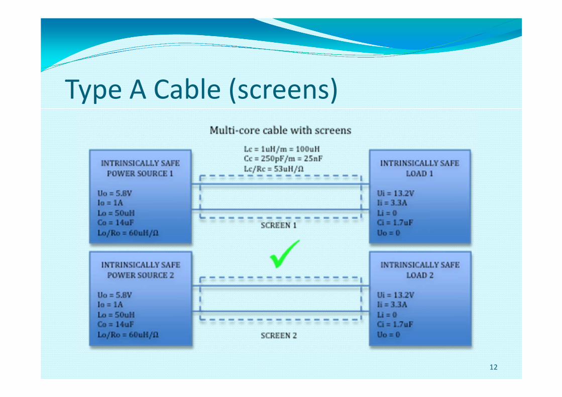
Type A Cable (screens)
12

Type B cable (Risk Assessment - Pass)
13

Risk Assessment – Fail
� Cable is now treated as a type C cable.
� Therefore need to apply 2 short circuit faults and 4 open
circuit faults to determine safety of design.
� Apply faults to obtain most unsafe conditions.
� Maximum voltage (voltage addition).
� Maximum current (current addition).
� Take note of infallible connections of power supply
negative terminals – prevents voltage addition.
14

Type C Cable (Voltage Addition)
15

Permitted Capacitance
16

Infallible Common Connections
17

Type C Cable (Current Addition)
18

Determining Lo/Ro
19

Conclusion
� Ex i equipment standard AS/NZS 60079-11. ✓� Ex i system standard AS/NZS 60079-25. ✓� Installation standard AS/NZS 60079-14. ✗� Format of descriptive system document is now specified.
� System designer now has the tools (specified faults) to
conduct an assessment of individual Ex i circuits in cables
without screens.
20
