phase coexistence in sr0.70ca0.30tio3 studied through electron diffraction
TRANSCRIPT
Available online at www.sciencedirect.com
Solid State Sciences 10 (2008) 307e315www.elsevier.com/locate/ssscie
Phase coexistence in Sr0.70Ca0.30TiO3 studied throughelectron diffraction
Shahid Anwar*, N.P. Lalla
UGC-DAE Consortium for Scientific Research, University Campus, Khandwa Road, Indore 452001, India
Received 4 August 2007; received in revised form 10 September 2007; accepted 23 September 2007
Available online 2 October 2007
Abstract
A detailed structural study employing electron diffraction in selected area (SAD) and convergent beam electron diffraction (CBED) modes,followed by Rietveld analysis of the powder X-ray diffraction (XRD) data, has been carried out to identify the correct space group and to in-vestigate the possible phase coexistence in Sr0.70Ca0.30TiO3 (SCT30) ceramics. The occurrence of distinctly two types of wide-angle CBEDpatterns and the presence of mutually perpendicular A2 type GM-lines in the forbidden reflections do show the coexistence of Pnma phaseand a new orthorhombic phase with space group P21212 in SCT30. The occurrence of P21212 orthorhombic phase in SCT30 appears to be a resultof distortion in addition with the rigid tilt of BO6 octahedra. It so appears that the possibility of occurrence of P21212 for distorted perovskitestructures is yet to be theoretically investigated.� 2007 Elsevier Masson SAS. All rights reserved.
Keywords: Sr0.70Ca0.30TiO3; P21212 Space group; Phase coexistence; CBED
1. Introduction
The apparent simplicity of the perovskite structure belies thedifficulties in identifying the correct structure of many of thedistorted perovskite variants. The study of the evolution of crys-tallographic phases in perovskites, as a function of composition,temperature and pressure, is an area of continued interest. Mostof these structural transitions involve rigid tilts, B-site cationdisplacement and chemical ordering at A and B sites of ABO3
perovskite, and lead to a variety of structures [1e6]. The possi-ble perovskite structures appearing due to rigid tilts of octahedrahave been derived by Glazer [1,2]. These phases have been prac-tically realized in a variety of perovskite systems. Out of these,Sr1�xCaxTiO3 (SCT) has been the subject of a number ofstudies, but the results still remain in dispute. The end membersCaTiO3 and SrTiO3 occur in orthorhombic (Pnma) and cubic(Pm3m) structures, respectively, at room temperature.
* Corresponding author. Tel.: þ91 9993125744; fax: þ91 7312462294.
E-mail addresses: [email protected] (S. Anwar), [email protected].
in (N.P. Lalla).
1293-2558/$ - see front matter � 2007 Elsevier Masson SAS. All rights reserved.
doi:10.1016/j.solidstatesciences.2007.09.015
It might be expected that the substitution of Ca for Sr inSr1�xCaxTiO3 would produce the same structural sequenceas obtained on heating CaTiO3. McQuarrie [7] reported the oc-currence of cubic, tetragonal and orthorhombic phases asa function of composition. Ball et al. [8] have proposed threephase boundaries corresponding to the crossovers from cubic(Pm3m) to tetragonal (I4/mcm) for x> 0.05, from tetragonalto orthorhombic (Cmcm) at x> 0.35 and from Cmcm toPnma at x> 0.55. Granicher and Jakits [9] have reportedthat the Cmcm space group for the composition range0.35� x� 0.60 corresponds to the ‘nearly cubic’ phase. Cehet al. [10] proposed cubic to orthorhombic phase boundaryat x¼ 0.40. Altogether a different sequence of structureshave been proposed by Ranjan and Pandey [11] claimingthat the structure is not tetragonal but orthorhombic in thecomposition range 0.12� x� 0.40. Earlier proposed [11]Pnma structure was later reanalyzed to be Imma based on im-proved data quality [12]. The assignment to Imma is basedlargely on the Rietveld refinement of lab XRD and neutronscattering data, which is supported by the observed asymmetryin the Eg lines and broad bands in Raman spectra [13]. There
308 S. Anwar, N.P. Lalla / Solid State Sciences 10 (2008) 307e315
are very few reports on electron diffraction in these composi-tion ranges. Ranjan et al. [14] using electron diffractionshowed that the structure is cubic for x< 0.06, orthorhombicwith different symmetry in the composition range of0.09< x� 1.0 and either tetragonal or orthorhombic for0.06< x< 0.09. Howard et al. [15,16] assigned the tetragonalspace group I4/mcm for the room temperature SCT30, whereasa recent report by Woodward et al. [17], based on electron dif-fraction studies, reports P21/m structure for SCT30. In factWoodward et al. [17] have given a new sequence of structuresin the phase diagram. According to them the space groups arePm3m for x¼ 0, I4/mcm for x< 0.2, C2/m for x¼ 0.2, P21/mfor 0.2< x< 0.6 and Pnma for x> 0.6. Ranjan et al. [14] haveproduced micro-diffraction patterns corresponding to all thethree mutually orthogonal zones [100], [010], and [001]. How-ever, we would like to emphasize that, practically it is not pos-sible to get all three above zone patterns from the same graindue to mechanical limitation of the b-tilt of a double-tiltholder and hence there is possibility of mixing of patternsfrom different phases. Woodward et al. [17] have givena method in which one needs to collect patterns from differentgrains and decide based on the statistics of observing zone pat-terns with certain type of reflections. Howard et al. [16] intheir recent report based on the analysis of SAD patternshave assigned I4/mcm space group to SCT30. However, afterdigital enhancement, weak but clear presence of superlatticereflections were found, which are neither expected in anybody centered lattice nor it will be produced by double diffrac-tion in Imma and I4/mcm phases.
Thus keeping in view the above-mentioned controversieswe have carried out extensive structural study of SCT30, lead-ing to the unequivocal identification of its space group. This isa composition, which has been studied by various groupsthrough X-ray diffraction, neutron diffraction, electron diffrac-tion and Raman scattering. We have studied the room-temper-ature crystal structure of SCT30 using TEM. We havefollowed the conventional way of determining symmetry ele-ments and space groups (Tanaka [18], William and Carter[19], Gjfnnes and Moodie, [20] and Morniroli and Steeds[21]). For this we have recorded selected area (SAD) and con-vergent beam electron diffraction (CBED) patterns from singledomain. By its comparison with the simulated ones, we havediscarded the possibility of some of the expected space groups.Our decisions are purely based on the absence or presence ofcertain reflections and diffraction features like superlatticespots and GM-lines in an otherwise properly processed dif-fraction patterns. Our diffraction studies show the coexistenceof Pnma with a new orthorhombic phase with space groupP21212. We emphasize that the possibility of P21212 for adistorted perovskite structure has yet not been theoreticallyinvestigated.
2. Experimental
The SCT30 sample was prepared through solid-state reac-tion route using high purity (99.99%) powders of SrCO3,CaCO3 and TiO2 [11,12]. The final sintered pellets were gently
crushed to fine powder and subsequently annealed at 600 �Cfor w10 h for removing residual strain present in the grains.Only the final heat-treated powder was used for the diffractionstudies as described below. The powder was subjected to struc-tural and phase purity characterizations using powder X-raydiffraction (XRD). The XRD was carried out using Cu KaX-ray on a Rigaku make diffractometer working in BraggeBrentano para-focusing geometry and mounted on a rotatinganode X-ray generator operating at 15 kW output power. Thecomposition of the synthesized sample was verified usingEDAX. The complete absence of any contrast variation, ap-pearing due to different effective-Z for different phases ob-served during backscattered SEM, confirmed the phasepurity of the sample. EDAX revealed that the compositionof SCT30 was the same within the typical error of EDAX tothat of the intended one.
Transmission electron microscopy (TEM) was carried outemploying Tecnai G220 TEM (FEI) operating at 200 kV,equipped with LaB6 filament and a CCD camera (Megaview SIS). Sample for TEM observation was made by dispers-ing the annealed powders in methanol and drying a drop of thedispersion on a perforated carbon coated copper grid. TEMwas performed in imaging, SAD, micro-diffraction andCBED modes. For TEM observations, a double-tilt holder(a¼�45� and b¼�25�) was used. Whenever necessarily re-quired, the SAD patterns were recorded by tilting the requiredzone exactly along the beam direction. CBED patterns havebeen obtained using 10-mm condenser aperture with incidentelectron beam converging to an effective spot size of 50 nmon the specimen. The small spot size assures good spatial res-olution and minimizes the likelihood of any significant thick-ness and orientation variations within the diffracting specimenvolume. All SADs and low-angle CBEDs were recorded atcamera lengths of 860 mm and wide-angle CBEDs were re-corded at 265 mm. All the TEM photographs particularlySAD and CBED patterns, which have been presented here,are properly enhanced for clear visibility of even the weakestdetails like weak superlattice spots, HOLZ (Higher order Lauezone) rings and GM-lines. In general in a pristine diffractionpattern, these features may remain undetected otherwise.This was done using the ‘‘Analysis’’ software made availablewith the CCD camera. The decisions regarding the correctspace group has been taken based on the systematic absenceof reflections and presence of proper signatures of symmetryelements as indicated by the presence of GM-lines [18,19]appearing in kinematically forbidden reflections in CBEDpatterns. During TEM analysis, EDAX was also carried outand the composition was found to match with the intendedone within the typical error of EDAX.
3. Results and discussions
Fig. 1a depicts Rietveld refined [22] X-ray diffraction pat-terns of SCT30 corresponding to different space groups. Thesepatterns have been vertically enlarged to make some necessarydetails clear. Same fitting strategy was followed for each spacegroup case. The five space groups under consideration differ

P21/m
Inte
nsit
y (a
.u.)
I4/mcm
Imma
Pnma
30 40 50 60 70 80 90
Cmcm
2θ 2θ
Inte
nsit
y (a
rb. u
nits
)
51 52 53
Pnma
Imma
I4/mcm
P21/m
61 62 63 72 74
Cmcm
(b)(a)
Fig. 1. (a) Rietveld refined X-ray diffraction patterns of Sr0.70Ca0.30TiO3 using different space groups. (b) Expanded views of some of the superlattice peaks from
the fitted XRD pattern shown in Fig. 1a. It shows that the fit corresponding to P21/m is not good.
309S. Anwar, N.P. Lalla / Solid State Sciences 10 (2008) 307e315
only in the style of rigid rotation of the BO6 octahedral unitwith respect to its most symmetric orientation in the basic pe-rovskite structure with Pm3m space group. Therefore the fit-ting strategies differed only in the choice of extra Wyckoffpositions and switching on and off the relaxations as permittedby the space group being considered. Enlarged views of fewselected regions of the fitted patterns having superlattice peakshave also been shown in Fig. 1b, so that the fit qualities corre-sponding to different space groups can be vividly judged.However, it was not possible to select the correct space grouponly on the basis of Rietveld refinement, since out of five, thePnma, Imma, Cmcm and I4/mcm gave comparable c2 values.But of course the fit based on P21/m did not give a good qual-itative fit even for the basic perovskite peaks itself. The en-larged views corresponding to P21/m clearly show that the
Fig. 2. (a) Bright and (b) dark-field electron micrographs of an electron transpare
different phases.
superlattice peaks are not properly fitted. This indicates thatthe space group is definitely not P21/m. The fit qualities corre-sponding to the remaining four possibilities, Imma, I4/mcm,Cmcm and Pnma, are equally good and hence based entirelyon the comparison of the fit and the c2 values; it was not pos-sible to distinguish the unique one.
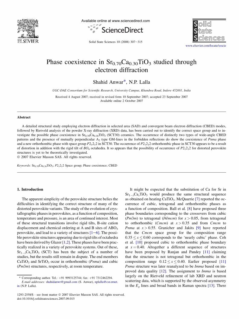
TEM exploration of SCT30 invariably showed two differ-ent types of regions in the same single crystal grain. Fig. 2ashows a typical bright-field and Fig. 2b the correspondingdark-field micrographs of a similar single crystal grain. Thedark-field micrograph clearly shows the presence of domainin the single crystal grain. The domains giving different dif-fraction patterns have been marked by R1 and R2. It shouldbe noted that the two domains have very weak contrast differ-ence in the bright-field image but are rather better clear in dark
nt thin particle of SCT30 showing the domains R1 and R2 of two structurally
310 S. Anwar, N.P. Lalla / Solid State Sciences 10 (2008) 307e315
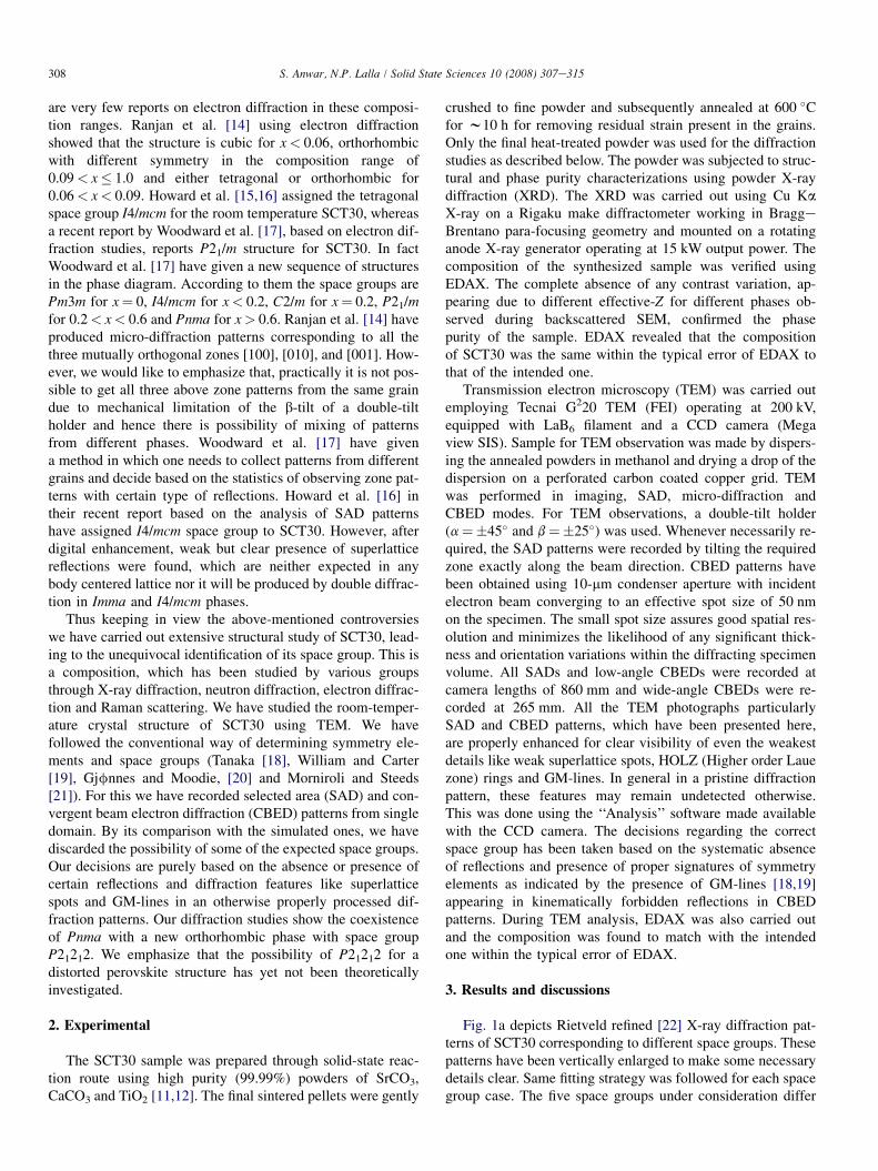
field. The SAD patterns from these two regions were qualita-tively same, but the structural phase of these two regions gotdifferentiated in the wide-angle CBED patterns taken fromthese. Fig. 3aef depicts the SAD (a and b), wide-angleCBED (c and d) and low-angle CBED (e and f) from regionsR1 and R2, respectively. It can be noticed that although theSAD patterns from R1 and R2 look similar the CBEDs are dif-ferent. CBED from R2, Fig. 3d, does not show the intense firstorder Laue zone (FOLZ) ring as that from region R1, seeFig. 3c. This observation clearly indicates the coexistence oftwo phases in the same single crystal grain. The presence ofFOLZ corresponding to the zone shown in Fig. 3d was real-ized only when the pattern was recorded in a considerably
(c)
SOLZFOLZ
(a)
a*c*
(e) GM-lines
m1m2
a*c*
Fig. 3. Zone axis patterns from SCT30, SAD (a and b), wide-angle CBED (c and d
Presence of a FOLZ corresponding to b-parameter of 7.78 A can be clearly seen in
zone [001] of P21212. Mutually perpendicular GM-lines along a*c* with mirrors
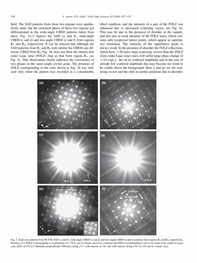
tilted condition, and the intensity of a part of the FOLZ wasenhanced due to decreased scattering vector, see Fig. 4a.This may be due to the presence of disorder in the sample,and also due to weak intensity of the FOLZ layer, which con-tains only reciprocal lattice points, which appear as superlat-tice formation. The intensity of the superlattice peaks isalways weak. In the presence of disorder the FOLZ reflections,which have w20 times large scattering vectors than the ZOLZ(Zero order Laue zone) ones, will suffer large phase change ofw2p exp( g $ Dr) in its scattered amplitude and in the case ofalready low scattered amplitude this may become too weak tobe visible above the background. Here g and Dr are the scat-tering vector and the shift in atomic positions due to disorder.
(f)
a*b*
GM-lines
No mirrors
(d)
SOLZ
a*b*
(b)
) and low-angle CBED (e and f) patterns from regions R1 and R2, respectively.
(c) whereas the FOLZ corresponding to (d) is too weak to be visible in exact
in (3e) and with mirrors along a*b* in (3f) can be clearly seen.
a*
b*
a*
b*
FOLZ SOLZ
(a) (b) (c)
Fig. 4. (a) Wide-angle CBED patterns recorded in tilted geometry from region R2. Presence of FOLZ corresponding to [001] zone of P21212 can be seen. (b and c)
(000) CBED disks showing the presence of 2mm BF mirrors’ symmetry.
311S. Anwar, N.P. Lalla / Solid State Sciences 10 (2008) 307e315
In tilted condition the g-vector will be smaller and hence theout of phase amplitude will also be smaller, making a partof the FOLZ visible and verifying its presence. The spacingcorresponding to FOLZ rings was determined to bew7.78 A, which matches with the long axis (2a0) of theknown orthorhombic cell with lattice parameters O2a0, O2a0
and 2a0, where a0 (w3.9 A) is the lattice parameter of thepseudo-perovskite cell. During TEM observation we realizedthat in aggregate the volume fraction of R1-like regions isless as compared to that of the R2. The typical thickness ofany such grains giving the above SAD patterns was measured,employing contamination cap growth technique, to bew50 nm [19].
The SADs in Fig. 3a and b were measured and found to cor-respond to the same orthorhombic cell with lattice parametersO2a0, O2a0 and 2a0. The superlattice spots appearing as a re-sult of ordering in the basic Pm3m structure are indicated byarrows and the basic reciprocal cells are also highlighted bysquares. The occurrence of identical reciprocal net from re-gions R1 and R2 but the observed distinct difference in corre-sponding CBEDs clearly tells that the regions R1 and R2
correspond to coexistence of two different phases emergingfrom the same basic phase Pm3m. The detailed space groupanalysis of these regions was carried out following the conven-tional technique as described by Tanaka [18], William andCarter [19], Gjfnnes and Moodie [20], and Morniroli andSteeds [21]. The technique requires determination of bright-field (BF) symmetry of the (000) disk and dark-field (DF)symmetry of the whole pattern. The BF symmetry was deter-mined to be 2mm, see Fig. 4b and c. The DF symmetry of thelow-angle CBED pattern as shown in Fig. 3e is 2mm. The mir-rors m1 and m2 are highlighted in the corresponding inset. TheBF mirrors were found to be coincident with the DF mirrors.The presence of A2 type GeM (GjfnneseMoodie) lines [19]parallel to a* and c* in forbidden (500) and (005) reflections(disks) of CBED are indicated by arrows in Fig. 3e. GM-linesappear as the dynamical absence of intensity along the line of
exact Bragg condition in kinematically forbidden reflections.The forbidden nature of (h00) and (0k0); h and k being odd in-tegers, reflections was confirmed through the tilt experiments.Presence of mutually perpendicular A2 type GM-lines parallelto the mirrors 2mm of DF symmetry [19] reveals the presenceof two mutually perpendicular glide planes containing the[010] axis. The presence of mutually perpendicular glideplanes passing through [010] discard the possibility of P21/mand Cmcm. The presence of 2mm both in the WP symmetryand BF symmetry indicates that the diffraction group is 2mmor 2mm1R and hence the possible point groups for an ortho-rhombic cell are mm2 and mmm [19,23]. Under the pointgroup mmm the possibility out of the above-mentioned spacegroups with two mutually perpendicular glide planes con-verges to Pnma (Pbnm) [24], which is already known for theseceramics.
Contrary to the CBED in Fig. 3e from region R1, the CBEDin Fig. 3f from region R2 does not show any DF mirror, as in-dicated by dotted lines in Fig. 3f. But the presence of GM-lines in kinematically forbidden disks (500) and (050) is farbetter clear than in Fig. 3e. The forbidden character of thesereflections was confirmed through tilt experiments. It can benoticed that there are no mirrors parallel to a*c* and b*c*planes and hence the DF symmetry is only 2-fold. The BFsymmetry was determined to be 2mm; the two mirrors beingperpendicular to a* and b*, see Fig. 4b and c. The presenceof 2mm BF symmetry corresponding to the phase found in re-gions R1 and R2 is identical and hence only one of them hasbeen shown in Fig. 4b and c. The observed GM-lines areperpendicular to the BF mirrors. Presence of mutually perpen-dicular A2 type GM-lines, not having any DF mirror but eachperpendicular to BF mirrors, set in 2mm symmetry, reveals thepresence of two mutually perpendicular screw axes normal tothe [001] (Tanaka [18] and William and Carter [19]). The pres-ence of 2-fold in WP symmetry and 2mm in BF symmetry in-dicates that the diffraction symmetry is 2mRmR and thepossible point group is 222 only [19,23]. Under the point
Ti1
Ti1
Ti1Ti1
O1 O1Ti1
O1 O1
O4
O3
O4
O3
Sr1
Sr2
O4
O3
Ti2
Ti2
Ti2 Ti2Ti2
O2
O2
O2
O2
O4Sr1
Sr2
Sr2
O3
O3
Sr2Sr1
Sr1
O4
Ti1
Ti1
Ti1Ti1
O1 O1Ti1
O1 O1
Ti
Ti
Ti
Ti
Ti
Ti
Ti
Ti
Ti
Ti
Ti Ti
Ti
Ti
c
ab
(a) (b)
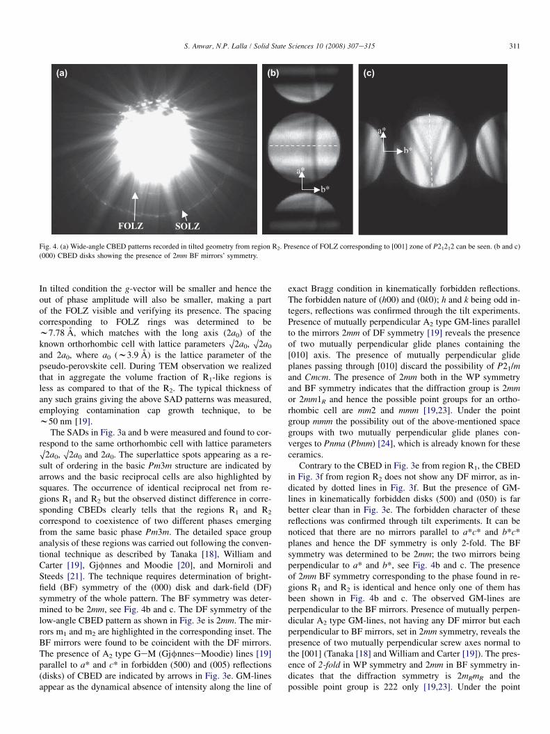
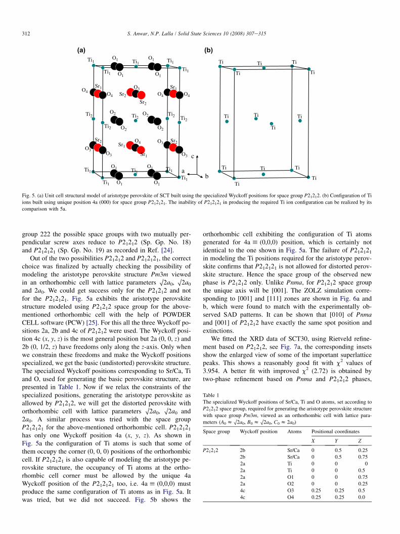
Fig. 5. (a) Unit cell structural model of aristotype perovskite of SCT built using the specialized Wyckoff positions for space group P21212. (b) Configuration of Ti
ions built using unique position 4a (000) for space group P212121. The inability of P212121 in producing the required Ti ion configuration can be realized by its
comparison with 5a.
Table 1
The specialized Wyckoff positions of Sr/Ca, Ti and O atoms, set according to
P21212 space group, required for generating the aristotype perovskite structure
with space group Pm3m, viewed as an orthorhombic cell with lattice para-
meters (A0 z O2a0, B0 z O2a0, C0 z 2a0)
Space group Wyckoff position Atoms Positional coordinates
X Y Z
P21212 2b Sr/Ca 0 0.5 0.25
2b Sr/Ca 0 0.5 0.75
2a Ti 0 0 0
2a Ti 0 0 0.5
2a O1 0 0 0.75
2a O2 0 0 0.25
4c O3 0.25 0.25 0.5
4c O4 0.25 0.25 0.0
312 S. Anwar, N.P. Lalla / Solid State Sciences 10 (2008) 307e315
group 222 the possible space groups with two mutually per-pendicular screw axes reduce to P21212 (Sp. Gp. No. 18)and P212121 (Sp. Gp. No. 19) as recorded in Ref. [24].
Out of the two possibilities P21212 and P212121, the correctchoice was finalized by actually checking the possibility ofmodeling the aristotype perovskite structure Pm3m viewedin an orthorhombic cell with lattice parameters O2a0, O2a0
and 2a0. We could get success only for the P21212 and notfor the P212121. Fig. 5a exhibits the aristotype perovskitestructure modeled using P21212 space group for the above-mentioned orthorhombic cell with the help of POWDERCELL software (PCW) [25]. For this all the three Wyckoff po-sitions 2a, 2b and 4c of P21212 were used. The Wyckoff posi-tion 4c (x, y, z) is the most general position but 2a (0, 0, z) and2b (0, 1/2, z) have freedoms only along the z-axis. Only whenwe constrain these freedoms and make the Wyckoff positionsspecialized, we get the basic (undistorted) perovskite structure.The specialized Wyckoff positions corresponding to Sr/Ca, Tiand O, used for generating the basic perovskite structure, arepresented in Table 1. Now if we relax the constraints of thespecialized positions, generating the aristotype perovskite asallowed by P21212, we will get the distorted perovskite withorthorhombic cell with lattice parameters O2a0, O2a0 and2a0. A similar process was tried with the space groupP212121 for the above-mentioned orthorhombic cell. P212121
has only one Wyckoff position 4a (x, y, z). As shown inFig. 5a the configuration of Ti atoms is such that some ofthem occupy the corner (0, 0, 0) positions of the orthorhombiccell. If P212121 is also capable of modeling the aristotype pe-rovskite structure, the occupancy of Ti atoms at the ortho-rhombic cell corner must be allowed by the unique 4aWyckoff position of the P212121 too, i.e. 4a h (0,0,0) mustproduce the same configuration of Ti atoms as in Fig. 5a. Itwas tried, but we did not succeed. Fig. 5b shows the
orthorhombic cell exhibiting the configuration of Ti atomsgenerated for 4a h (0,0,0) position, which is certainly notidentical to the one shown in Fig. 5a. The failure of P212121
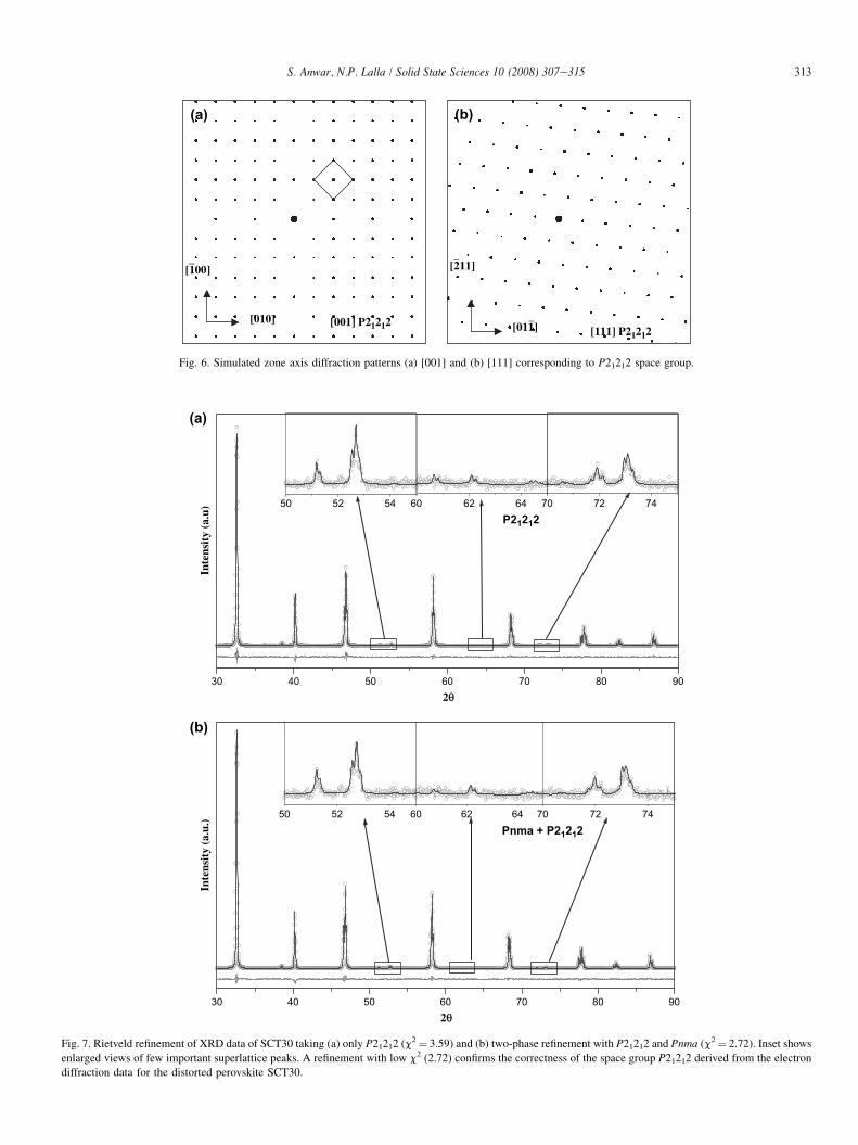
in modeling the Ti positions required for the aristotype perov-skite confirms that P212121 is not allowed for distorted perov-skite structure. Hence the space group of the observed newphase is P21212 only. Unlike Pnma, for P21212 space groupthe unique axis will be [001]. The ZOLZ simulation corre-sponding to [001] and [111] zones are shown in Fig. 6a andb, which were found to match with the experimentally ob-served SAD patterns. It can be shown that [010] of Pnmaand [001] of P21212 have exactly the same spot position andextinctions.
We fitted the XRD data of SCT30, using Rietveld refine-ment based on P21212, see Fig. 7a, the corresponding insetsshow the enlarged view of some of the important superlatticepeaks. This shows a reasonably good fit with c2 values of3.954. A better fit with improved c2 (2.72) is obtained bytwo-phase refinement based on Pnma and P21212 phases,
[100]_
[010]
(a)
[001] P21212
[211]_
[011]_
(b)
[111] P21212
Fig. 6. Simulated zone axis diffraction patterns (a) [001] and (b) [111] corresponding to P21212 space group.
30 40 50 60 70 80 90
P212
12
Inte
nsit
y (a
.u) 50 52 54 60 62 64 70 72 74
(a)
30 40 50 60 70 80 90
Pnma + P212
12
Inte
nsit
y (a
.u.)
50 52 54 60 62 64 70 72 74
(b)
2θ
2θ
Fig. 7. Rietveld refinement of XRD data of SCT30 taking (a) only P21212 (c2¼ 3.59) and (b) two-phase refinement with P21212 and Pnma (c2¼ 2.72). Inset shows
enlarged views of few important superlattice peaks. A refinement with low c2 (2.72) confirms the correctness of the space group P21212 derived from the electron
diffraction data for the distorted perovskite SCT30.
313S. Anwar, N.P. Lalla / Solid State Sciences 10 (2008) 307e315
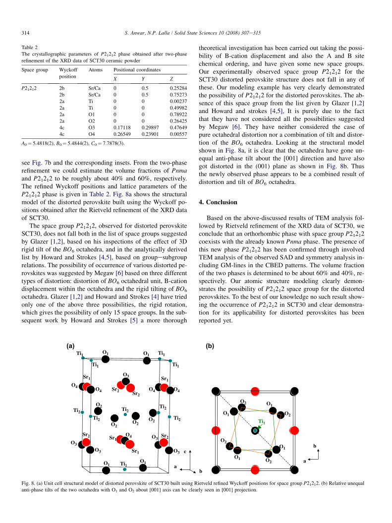
Table 2
The crystallographic parameters of P21212 phase obtained after two-phase
refinement of the XRD data of SCT30 ceramic powder
Space group Wyckoff
position
Atoms Positional coordinates
X Y Z
P21212 2b Sr/Ca 0 0.5 0.25284
2b Sr/Ca 0 0.5 0.75273
2a Ti 0 0 0.00237
2a Ti 0 0 0.49982
2a O1 0 0 0.78922
2a O2 0 0 0.26425
4c O3 0.17118 0.29897 0.47649
4c O4 0.26549 0.23901 0.00557
A0¼ 5.4818(2), B0¼ 5.4844(2), C0¼ 7.7878(3).
314 S. Anwar, N.P. Lalla / Solid State Sciences 10 (2008) 307e315
see Fig. 7b and the corresponding insets. From the two-phaserefinement we could estimate the volume fractions of Pnmaand P21212 to be roughly about 40% and 60%, respectively.The refined Wyckoff positions and lattice parameters of theP21212 phase is given in Table 2. Fig. 8a shows the structuralmodel of the distorted perovskite built using the Wyckoff po-sitions obtained after the Rietveld refinement of the XRD dataof SCT30.
The space group P21212, observed for distorted perovskiteSCT30, does not fall both in the list of space groups suggestedby Glazer [1,2], based on his inspections of the effect of 3Drigid tilt of the BO6 octahedra, and in the analytically derivedlist by Howard and Strokes [4,5], based on groupesubgrouprelations. The possibility of occurrence of various distorted pe-rovskites was suggested by Megaw [6] based on three differenttypes of distortion: distortion of BO6 octahedral unit, B-cationdisplacement within the octahedra and the rigid tilting of BO6
octahedra. Glazer [1,2] and Howard and Strokes [4] have triedonly one of the above three possibilities, the rigid rotation,which gives the possibility of only 15 space groups. In the sub-sequent work by Howard and Strokes [5] a more thorough
(a)
Ti1
Ti1
Ti1
Ti1
O1 O1
Ti1O1O1
O4
O3
O4
O3
Sr1
Sr2
O4
O3
Ti2Ti2
Ti2
Ti2
Ti2O2
O2O2
O2
O4
Sr1
Sr2 Sr2
O3
O3
Sr2 Sr1
Sr1
O4
c
a
Fig. 8. (a) Unit cell structural model of distorted perovskite of SCT30 built using R
anti-phase tilts of the two octahedra with O1 and O2 about [001] axis can be clear
theoretical investigation has been carried out taking the possi-bility of B-cation displacement and also the A and B sitechemical ordering, and have given some new space groups.Our experimentally observed space group P21212 for theSCT30 distorted perovskite structure does not fall in any ofthese. Our modeling example has very clearly demonstratedthe possibility of P21212 for the distorted perovskites. The ab-sence of this space group from the list given by Glazer [1,2]and Howard and strokes [4,5], It is purely due to the factthat they have not considered all the possibilities suggestedby Megaw [6]. They have neither considered the case ofpure octahedral distortion nor a combination of tilt and distor-tion of the BO6 octahedra. Looking at the structural modelshown in Fig. 8a, it is clear that the octahedra have gone un-equal anti-phase tilt about the [001] direction and have alsogot distorted in the (001) plane as shown in Fig. 8b. Thusthe newly observed phase appears to be a combined result ofdistortion and tilt of BO6 octahedra.
4. Conclusion
Based on the above-discussed results of TEM analysis fol-lowed by Rietveld refinement of the XRD data of SCT30, weconclude that an orthorhombic phase with space group P21212coexists with the already known Pnma phase. The presence ofthis new phase P21212 has been confirmed through involvedTEM analysis of the observed SAD and symmetry analysis in-cluding GM-lines in the CBED patterns. The volume fractionof the two phases is determined to be about 60% and 40%, re-spectively. Our atomic structure modeling clearly demon-strates the possibility of P21212 space group for the distortedperovskites. To the best of our knowledge no such result show-ing the occurrence of P21212 in SCT30 and clear demonstra-tion for its applicability for distorted perovskites has beenreported yet.
(b)
O1
O2 O1
O2
O1
O2O1
O2
Ti1
b
a
b
ietveld refined Wyckoff positions for space group P21212. (b) Relative unequal
ly seen in [001] projection.
315S. Anwar, N.P. Lalla / Solid State Sciences 10 (2008) 307e315
Acknowledgements
Authors gratefully acknowledge Dr. P. Chaddah, the Direc-tor and Prof. Ajay Gupta, the Center Director of UGC-DAECSR, Indore for their encouragement and interest in thework. We thankfully acknowledge the fruitful discussionswith Prof. O.N. Siravastava, Department of Physics andProf. D. Pandey, SMST, BHU, Varanasi, India. One of the au-thors, Shahid Anwar, would also like to acknowledge CSIR,India for the financial support as an SRF.
References
[1] A.M. Glazer, Acta Crystallogr., B 28 (1972) 3384.
[2] A.M. Glazer, Acta Crystallogr., A 31 (1975) 756.
[3] D.I. Woodward, I.M. Reaney, Acta Crystallogr., B 61 (2005) 387.
[4] C.J. Howard, H.T. Strokes, Acta Crystallogr., B 54 (1998) 782.
[5] C.J. Howard, H.T. Strokes, Acta Crystallogr., A 61 (2005) 93.
[6] H.D. Megaw, Crystal Structures e A Working Approach, W.B. Saunders,
Philadelphia, 1973.
[7] M. McQuarrie, J. Am. Ceram. Soc. 38 (1955) 444.
[8] C.J. Ball, B.D. Begg, D.J. Cookson, G.J. Thorogood, E.R. Vance, J. Solid
State Chem. 139 (1998) 238e247.
[9] H. Granicher, O. Jakits, Nuovo Cimento 9 (Suppl.) (1954) 480.
[10] M. Ceh, V. Krasevec, D. Kolar, J. Solid State Chem. 68 (1987) 68.
[11] R. Ranjan, D. Pandey, J. Phys.: Condens. Matter 13 (2001) 4239e4249
4251e4266.
[12] S.K. Mishra, R. Ranjan, D. Pandey, J. Appl. Phys. 91 (2002) 4447.
[13] P. Ranson, R. Ouillon, J.P. Pinan-Lucarre, Ph Pruzan, S.K. Mishra,
R. Ranjan, D. Pandey, J. Raman Spectrosc. 36 (2005) 898e911.
[14] R. Ranjan, D. Pandey, W. Schuddinck, O. Richard, P.D. Meulencere,
J.V. Landuyt, G.V. Tandeloo, J. Solid State Chem. 162 (2001) 20e28.
[15] C.J. Howard, R.L. Withers, B.J. Kennedy, J. Solid State Chem. 160
(2001) 8e12.
[16] C.J. Howard, R.L. Withers, Z. Zhang, K. Osaka, K. Kato, M. Takata, J.
Phys.: Condens. Matter 17 (2005) L459.
[17] D.I. Woodward, P.L. Wise, W.E. Lee, I.M. Reaney, J. Phys.: Condens.
Matter 18 (2006) 2401.
[18] M. Tanaka, J. Electron Microsc. Technol. 13 (1989) 27e39.
[19] D.B. Williams, C.B. Carter, Transmission Electron Microscopy e
Diffraction II, Platinum Press, New York, 1996.
[20] J. Gjfnnes, A.F. Moodie, Acta Crystallogr. 19 (1965) 65e67.
[21] J.P. Morniroli, J.W. Steeds, Ultramicroscopy 45 (1992) 219.
[22] J. Rodriguez-Carvajal, Physica B 192 (1993) 55e69.
[23] J.W. Steeds, R. Vincent, J. Appl. Crystallogr. 16 (1983) 317e324.
[24] International Tables for Crystallography, vol. A, Kluwer Academic,
1992.
[25] W. Kraus, G. Nolze, J. Appl. Crystallogr. 29 (1996) 301e303.