pfc abatement in the semiconductor industry 2009 - … gompel_pfc... · pfc abatement in the...
TRANSCRIPT

PFC Abatement in the Semiconductor Industry 2009
Joe Van GompelGlade Consulting, LLC
SESHA 31st International Symposium, Scottsdale AZMay 19 – 22, 2009

Overview
PFCs are stable and difficult to abateReactions and thermodynamics
Approaches to abatement of PFCsBurn‐wetPlasmaCatalyticThe HF QuestionCommercial SolutionsApplied Materials / Metron “Marathon”Centrotherm CT‐BW DAS EscapeEdwards Atlas, TPU, Sirius, ERIXGuild Trinity

Glade Consulting, LLC
Founded 2008, Austin TXJoe Van Gompel, PresidentPhD, physical organic chemistry, University of Illinois12 years as POU abatement specialist at (BOC) Edwards5 Years, FTIR Specialist at (Thermo) Mattson/Nicolet
Subfab operability consultingFabwide abatement strategiesPFC emissions reduction strategies
POU abatement – recommendations, uptimeVacuum pumpsEmissions testingPFC emissions auditsTraining seminars

PFC Gases in the Semiconductor Industry
The semiconductor industry phased in PFCs to replace chlorinated ODSs in the 1980sPFCs were nontoxic and didn’t deplete ozone
PFCs were heavily used in chamber cleans since the early 1990sPrimarily C2F6 and CF4, mostly phased out in favor of NF3Still a global warmer, but well‐utilized in chamber, so effect is minimized
Significant PFC consumption in etch, especially CF4 and CHF3Etch is major emission component in most modern fabsDifficult to optimize – need proper ratio of C, H, O, and F for anisotropic etch

5
Why PFCs are Such Potent Global Warming Gases
CF4 , C2 F6 , C3 F8
C2 F6C3 F8SF6
NF3
10 µ, 10,000 nm 3.3 µ, 3,333 nm5 µ, 5,000 nm
Visible light ‐ red 0.7 u, violet 0.36 u
CO2CO2 H2O H2O
Infrared spectrum of the atmosphere

Relative Stabilities of PFCs

Lifetimes and Stabilities
Fluorinated Gas Lifetime (years)CF4 50,000C2F6 10,000SF6 3200C3F8 2600c‐C4F8 3200NF3 740CHF3 270CH2F2 4.9
This is closely related to ease of abatement

PFC Gases are Very Stable Compounds
Carbon‐fluorine bond is strongest single bond in all of chemistryMultiple C‐F bonds on the same carbon enhance stabilityC‐C or C‐H bonds are weaker and decrease stabilityS‐F bond is strong too
Stability is reflected in atmospheric lifetimesStability is closely related to ease of abatementCF4C2F6, SF6C3F8, c‐C4F8, NF3CHF3, CH2F2, CHF3, C5F8, C4F6

Thermodynamics in Chemistry
Chemical reactions proceed preferentially “downhill” to lower energy products
These are exothermic reactions – they liberate heat
Chemical reactions can be forced to proceed “up hill”, where the products have more energy than the reactants – energy or heat have to be put into them
These are endothermic reactions – they absorb heat (get cold)
Thermodynamics simply tell if a reaction is favored or not. Thermodynamics are not always indicative of how fast a reaction will proceed (kinetics)
Starting Materials
Products
Products
H < 0 (Endothermic)
H > 0 (Exothermic)
Energy

Bond Strengths
BOND kcal/mol kJ/molF3C – F (CF4, Freon 14) 130 543F3C‐CF2 – F (C2F6, Freon116) 127 531H3C – F
108
452F3C – H (Freon 23)
106
444H3C – H (methane)
105

CF4 Decomposition Mechanisms
CF4 C (soot) + F2 ΔH = 9.5 eV/mol (+916 kJ/mol)Plasma Chemistry, Alexander Fridman, Cambridge University Press, 2008. ISBN 0521847354, 9780521847353
CF4 + O2 CO2 + 2F2 ΔH = +585 kJ/molCF4 + O2 + 2H2 CO2 + 4HF ΔH = ‐557 kJ/mol
ΔH is the “Heat of Reaction” ; how much heat is given off or must be added
Thermodynamics is “chemistry as the crow flies” – independent of the pathway. Getting to the oxidative decomposition with hydrogen is still difficult
Plus, now we have to dispose of HF …
Pyrolytic DecompositionCF4 2F2 + C ΔH = +916 kJ/mol
Oxidative DecompositionCF4 + O2 2F2 + CO2 ΔH = +585 kJ/mol
Oxidative Decomposition with hydrogenCF4 + O2 + 2 H2 2F2 + CO2 ΔH = ‐557 kJ/mol
CF4

Bond Energies are Not the Whole Story
Reactants Products
Going directly to the products (HEAT) may not be the best solution. Chemical environment will greatly affect reaction path and energy required.

Kinetics in Chemistry
Every reaction requires an activation energy EA to push reactants to change to products
Lower EA means less energy must be put into a reaction for it to proceed.Lower EA means a faster reaction
EA is strongly dependent on the reaction “mechanism”.Mechanism is the “roadmap”of how the reaction actually proceeds
Starting Materials
Products
Slow Reaction
Fast ReactionSmall EA
Large EA
Reaction
Energy
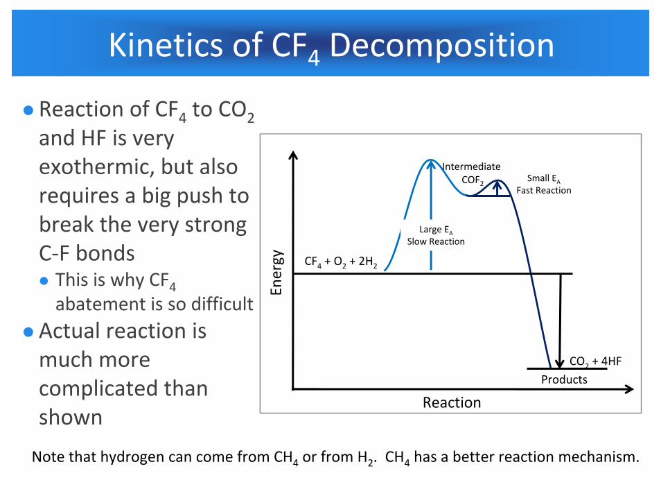
Kinetics of CF4 Decomposition
Reaction of CF4 to CO2and HF is very exothermic, but also requires a big push to break the very strong C‐F bondsThis is why CF4abatement is so difficult
Actual reaction is much more complicated than shown
CF4 + O2 + 2H2
Products
Reaction
Energy
Intermediate COF2
CO2 + 4HF
Large EASlow Reaction
Small EAFast Reaction
Note that hydrogen can come from CH4 or from H2. CH4 has a better reaction mechanism.
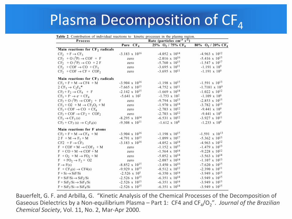
Plasma Decomposition of CF4
Bauerfelt, G. F. and Arbilla, G. “Kinetic Analysis of the Chemical Processes of the Decomposition of Gaseous Dielectrics by a Non‐equilibrium Plasma – Part 1: CF4 and CF4/O2”. Journal of the Brazilian Chemical Society, Vol. 11, No. 2, Mar‐Apr 2000.

CF4 as a Byproduct
Recombination of various plasma species to CF4 is common in plasma reactorsCF4 is most stable product of reaction between carbon and fluorineRecombination is circumvented by presence of hydrogen
C2F6, C3F8, C4F8, etc have all been shown to generate significant CF4 from plasma reactionsSome POU devices have also been shown to form CF4, but that is from F2 in a rich CH4 flame
CF4 abatement is a major consideration for any PFC emissions reduction strategy

Technological Approaches to PFC Abatement

Burn‐Wet Abatement
Burn‐wet is the primary POU abatement technologyFuel‐fired combustor (generally methane) followed by a wet scrubber to capture HF
Combustor settings for deposition gases is generally inadequate for PFC abatementSilane, H2, TEOS, WF6, NH3 burn much more readily PFC combustion generally requires additional fuel O2enrichment
Added expenseRecall that PFCs also have different stabilitiesCF4 < C2F6, SF6, C3F8 < C4F8, C5F8, CHF3, C4F8O, C4F6
Burn‐Wet Configurations
Most burn‐wet POU scrubbers can be configured to abate C2F6, C3F8, NF3, and SF6 relatively well (>95% in all cases).Little C2F6 and C3F8 used in 300‐mm fabs these days
Etch processes use CF4, SF6, CHF3, and C4F8 in significant quantitiesKeep in mind that CF4 may be a significant byproduct of plasma decomposition of other PFCs

PFC Abatement Efficiency
Burn‐wet POU abatement must be used within manufacturer’s recommended specifications for efficient PFC destructionTotal PFC flowSpecific PFC flow (e.g. CF4 limitations)
Total exhaust gas flowN2 purge flowFuel flow to combustorFuel flow to nozzle
O2 flowO2 quality (99%, 60%, 20% (air))Proper interface to tool
CF4 abatement tends to be most sensitive to conditionsSome manufacturers achieve 95‐99% under ideal conditions

Fuel Considerations
Methane, CH4, Natural GasSuperior flame chemistry, higher calorific contentGenerates appropriate free radicals to attack C‐F bonds
Slow flame front velocity and denatured for smell; saferNarrow flammable rangeInexpensiveReadily available
Hydrogen, H2Very expensive (only high purity H2 is found in fabs)No smell or taste
Very high flame front velocityVery wide flammable rangePoor flame chemistry for PFC abatement

Plasma Decomposition of PFCs
PFCs are decomposed all the time in plasma etchersLow pressure, low process flows, low efficiency (for CF4)Plasma as an abatement device is much less common
Plasma POU abatement can be pre‐pump (high vacuum) or post‐pump (atmospheric or near‐atmospheric pressure)Plasmas are very sensitive to pressure and total flow of gases
In the absence of fuel (vs. burn – wet), overall carbon footprint is very small despite high electrical usage
23
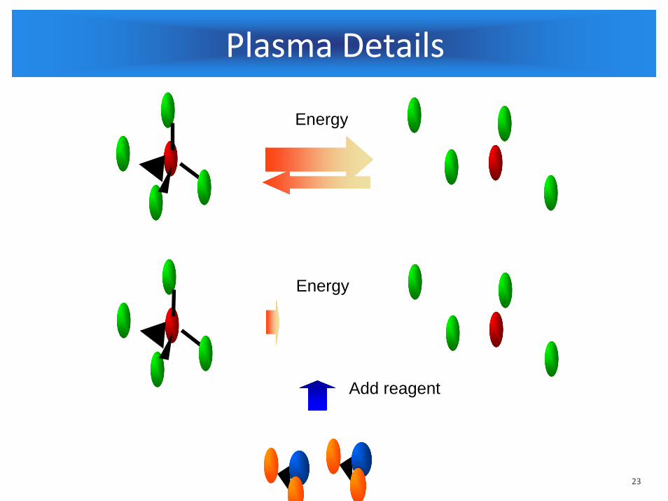
Plasma Details
Energy
Add reagent
Energy

24
Plasma Details
Energy
Energy

Pre‐Pump Plasma Abatement
Sematech Technology Transfer 98093561A‐ENG, Surface Wave Plasma (Texas A&M)Sematech Technology Transfer 98123605A‐ENG, Litmas “Blue” POU Plasma
Both of these were vacuum‐side abatementReagents (typically H2O) added to foreline to form CO, CO2, COF2, and HFCF4 DRE 90 – 99%Addition of materials to foreline made tool engineers nervousParticles, backstreaming
Few if any commercial sales
Post‐Pump Plasma Abatement
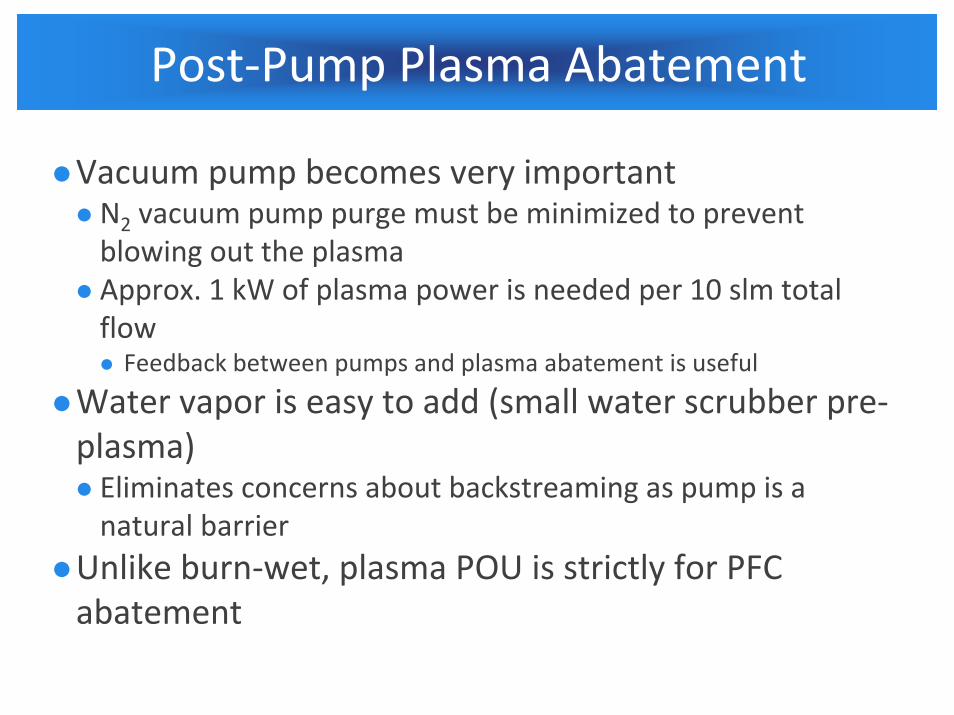
Vacuum pump becomes very importantN2 vacuum pump purge must be minimized to prevent blowing out the plasmaApprox. 1 kW of plasma power is needed per 10 slm total flowFeedback between pumps and plasma abatement is useful
Water vapor is easy to add (small water scrubber pre‐plasma)Eliminates concerns about backstreaming as pump is a natural barrier
Unlike burn‐wet, plasma POU is strictly for PFC abatement

Catalytic PFC Abatement
Catalytic PFC abatement utilizes a pre‐scrubber and a heated catalyst to convert PFCs to HF and CO or CO2Catalyst runs in 600oC – 750oC rangeMuch cooler than burn‐wet or plasmaDifferent reaction mechanismC2F6, C3F8, c‐C4F8 more difficult to abate than CF4Probably related to pore‐size of catalyst
Catalytic PFC Abatement requires pre‐scrubber (typically included) to protect catalyst from silicon halides or other materialsThese can poison or mask catalyst
In the absence of fuel (vs. burn – wet), overall carbon footprint is very small despite high electrical usage

Catalytic PFC Abatement vs Temperature
Small molecules require lower temperatures than larger molecules (Courtesy Guild Associates)
Temperature, oC
200 300 400 500 600 700 800
Con
vers
ion,
%
0
20
40
60
80
100
NF3
CHF3
SF6
CF4
C2F6
C3F8
c-C4F8
[PFC] = 1,000 ppm[H 2O] = 3.5 %

Multiple Chambers per POU Device
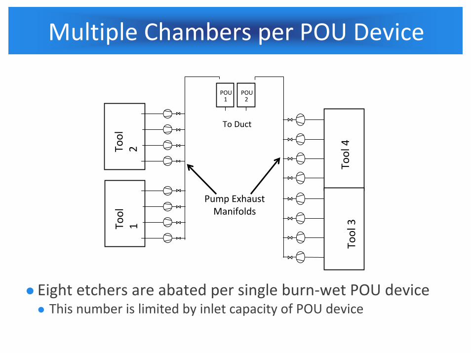
CVD processes are typically restricted to a single process chamber per inletPrevents combination of SiH4 and NF3 in pipework
Etch chambers may be combined if the process is the same No incompatible gas issuesMust be wary of total N2 flows from pump purges
Assume 4 inlets in Burn‐wet device, 50 slm max capacity per inlet. Set N2 pump purges to 15 slm; could abate 4 inlets x 3 chamber/inlet = 12 chambersRedundant configuration recommended
Multiple Chambers per POU Device
POU1
POU2
1
2
3
4
Tool
21
2
3
4
Tool 4
To Duct
Pump Exhaust Manifolds
1
2
3
4
Tool
1
1
2
3
4
Tool 3
Eight etchers are abated per single burn‐wet POU deviceThis number is limited by inlet capacity of POU device

Hydrogen Fluoride Byproduct
One liter of CF4 generates 4 liters of HF
PFC Liters HF Kg HFCF4 4 0.91 C2F6 6 0.87c‐C4F8 8 0.80SF6 6 0.82NF3 3 0.85
Abatement of PFCs requires an HF treatment facility be sized appropriatelyRequires careful consideration of annual usageMust also consider hydraulic capacity – lower concentration of HF means higher overall volume

Commercial Approaches to PFC Abatement

Air Liquide UPAS Plasma
Universal Plasma Abatement System

Applied Materials / Metron Marathon

Centrotherm CT – BW
CSK Burn – Wet

DAS ESCAPE Burn – Wet

Edwards TPU Burn – Wet

Edwards Atlas Burn – Wet

Edwards Sirius Plasma

Edwards ERIX HF Treatment

GST Burn – Wet

Guild Trinity Catalytic

Summary
PFC gases are chemically stable, making them difficult to abateAbatement technologies includeBurn – Wet (combustor followed by a water scrubber)PlasmaCatalytic
Burn – Wet is most prevalent Dedicated PFC Abatement doesn’t sell wellPlasma, catalytic systems are not common
Burn – Wet can be adapted to abate multiple etch chambersHF treatment capacity should not be overlooked