pedestal desk - images-na.ssl-images-amazon.com
TRANSCRIPT

Hardware List
Part List
Home Styles Customer Service: www.homestyles-furniture.com,[email protected], 888-680-7460, 877-831-0319
For assembly see instructions in carton 88 5530 182.
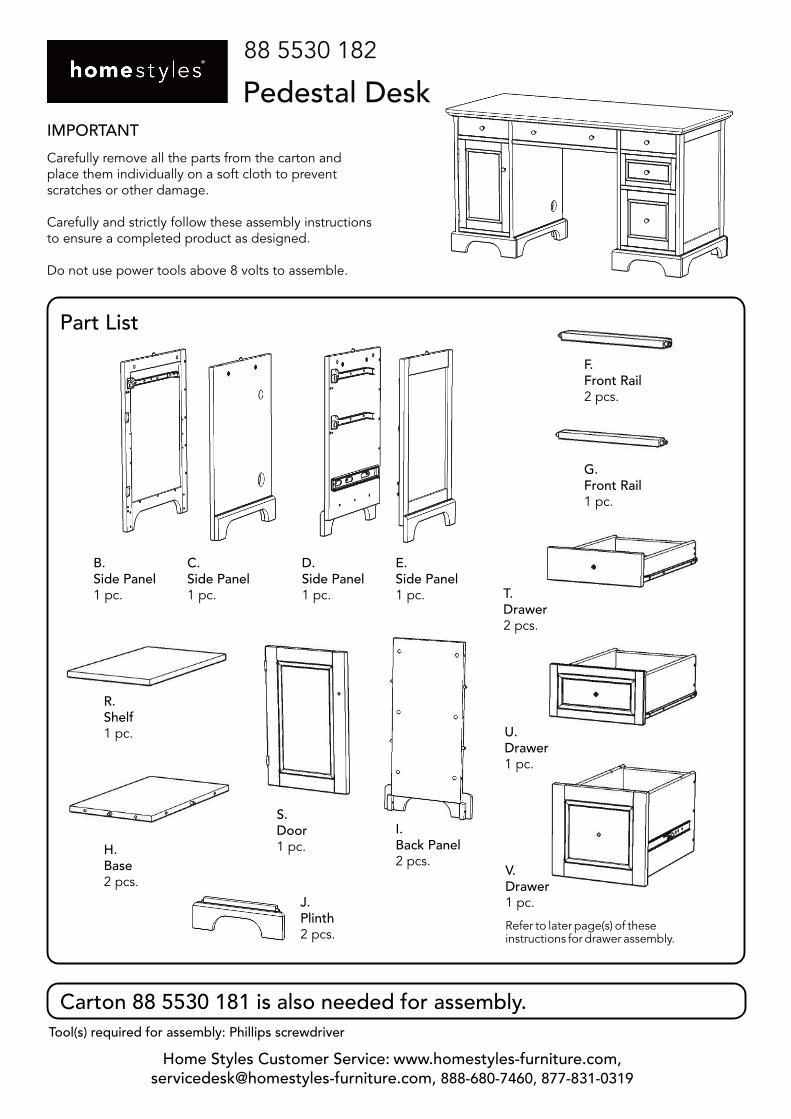
88 5530 181
Pedestal DeskIMPORTANT
Carefully remove all the parts from the carton andplace them individually on a soft cloth to preventscratches or other damage.
Carefully and strictly follow these assembly instructionsto ensure a completed product as designed.
Do not use power tools above 8 volts to assemble.
Hex Wrench1 pc.
Small Hex Wrench1 pc.
Cam Lock Screw48 pcs. (+2 extra)
Cam Lock48 pcs. (+6 extra)
M3.5x25Wood Screw (long)36 pcs. (+1 extra)
M3.5x13Wood Screw (short)16 pcs. (+1 extra)
Magnet1 pc.
M3x13Wood Screwfor Magnet2 pcs. (+1 extra)
Adjustable Pin4 pcs. (+1 extra)
M6x35Head Cap Bolt8 pcs. (+1 extra)
M4x15Machine Screw7 pcs.
L.Keyboard1 pc.
M.Keyboard Rail1 pc.
N.Keyboard Rail1 pc.
O.Keyboard Support1 pc.
A.Top1 pc.
W.Metal Strip2 pcs.
P.Keyboard Box1 pc.
Q.Keyboard Box1 pc.
K.Keyboard1 pc.
Knob7 pcs.
M3.5x25TaperedWood Screw (long)8 pcs. (+1 extra)
M3.5x10TaperedWood Screw (short)6 pcs. (+1 extra)
Part List
Home Styles Customer Service: www.homestyles-furniture.com,[email protected], 888-680-7460, 877-831-0319
Tool(s) required for assembly: Phillips screwdriver
IMPORTANT
Carefully remove all the parts from the carton andplace them individually on a soft cloth to preventscratches or other damage.
Carefully and strictly follow these assembly instructionsto ensure a completed product as designed.
Do not use power tools above 8 volts to assemble.
88 5530 182
Pedestal Desk
Carton 88 5530 181 is also needed for assembly.
B.Side Panel1 pc.
C.Side Panel1 pc.
D.Side Panel1 pc.
E.Side Panel1 pc.
F.Front Rail2 pcs.
G.Front Rail1 pc.
S.Door1 pc.
Refer to later page(s) of theseinstructions for drawer assembly.
R.Shelf1 pc.
H.Base2 pcs.
I.Back Panel2 pcs.
J.Plinth2 pcs.
T.Drawer2 pcs.
U.Drawer1 pc.
V.Drawer1 pc.
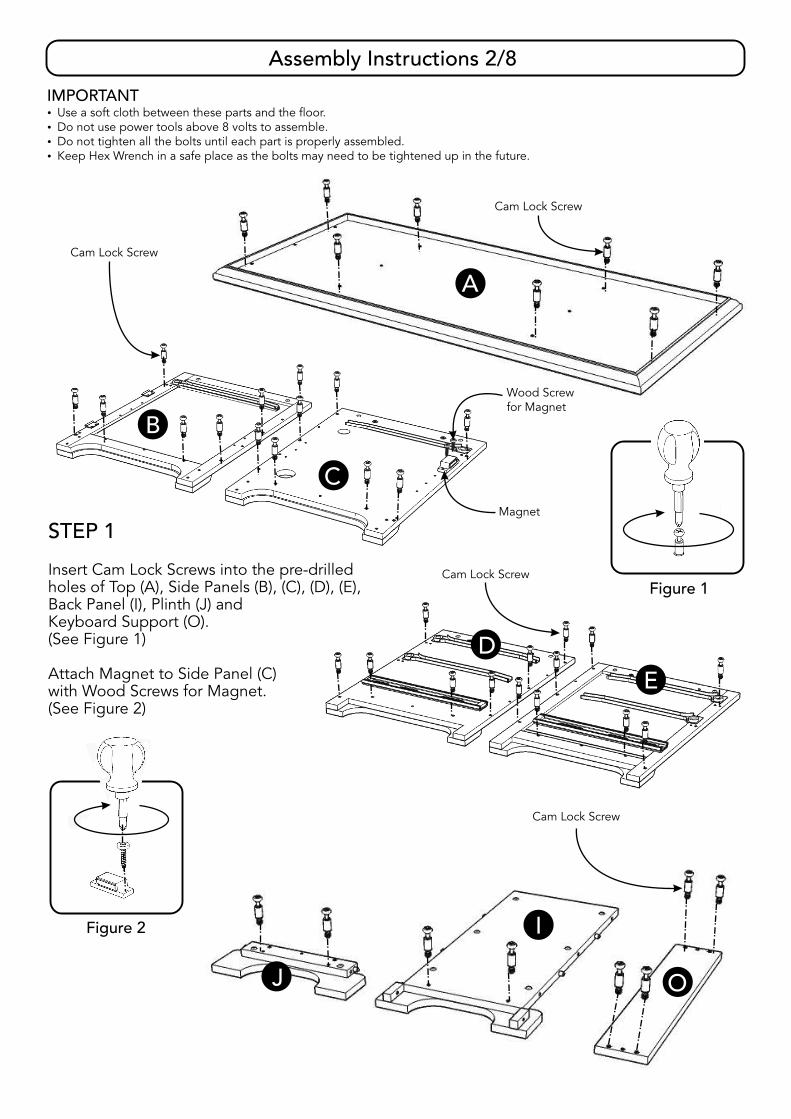
Assembly Instructions 2/8
IMPORTANT� Use a soft cloth between these parts and the floor.� Do not use power tools above 8 volts to assemble.� Do not tighten all the bolts until each part is properly assembled.� Keep Hex Wrench in a safe place as the bolts may need to be tightened up in the future.
Cam Lock Screw
Cam Lock Screw
C
B
J
I
O
A
Magnet
Wood Screwfor Magnet
Figure 2
Cam Lock Screw
Figure 1
D
E
Cam Lock Screw
STEP 1
Insert Cam Lock Screws into the pre-drilledholes of Top (A), Side Panels (B), (C), (D), (E),Back Panel (I), Plinth (J) andKeyboard Support (O).(See Figure 1)
Attach Magnet to Side Panel (C)with Wood Screws for Magnet.(See Figure 2)

Assembly Instructions 3/8
Cam LockTapered Wood Screw (long)
B
C
J
F
HI
STEP 2
Attach Front Rail (F), Base (H), Back Panel (I)and Plinth (J) to Side Panel (B) with Cam Locks. (See Figure 3)
Attach Side Panel (C) to unit with Cam Locks.
Insert Tapered Wood Screws (long) into pre-drilled holes of unit, then tighten.
Figure 3
D
E
J
F
H
G
I
Cam Lock
STEP 3
Attach Front Rails (F), (G), Base (H), Back Panel (I)and Plinth (J) to Side Panel (D) with Cam Locks.
Attach Side Panel (E) to unit with Cam Locks.
Insert Tapered Wood Screws (long) into pre-drilled holes of unit, then tighten.
Tapered Wood Screw (long)

Assembly Instructions 4/8
Figure 4
I
Figure 5
Head Cap Bolt
Cam Lock
M
N
PQ
O
STEP 4
Attach Keyboard Rails (M) and (N) to Keyboard Boxes (P) and (Q)with Head Cap Bolts. (See Figure 4)
Attach Keyboard Support (O) to unit with Cam Locks.
Attach unit from Steps 2 and 3 to unit with Head Cap Bolts.
Figure 6Wood Screw (short)
A
LL
K
Cam Lock
STEP 5
Attach Top (A) to unit with Cam Locks.
Attach Keyboard (K) to Keyboard (L)with Wood Screws (short).(See Figure 5)
Attach Knobs to keyboardwith Machine Screws.(See Figure 6)
Slide keyboard into position.
Part List
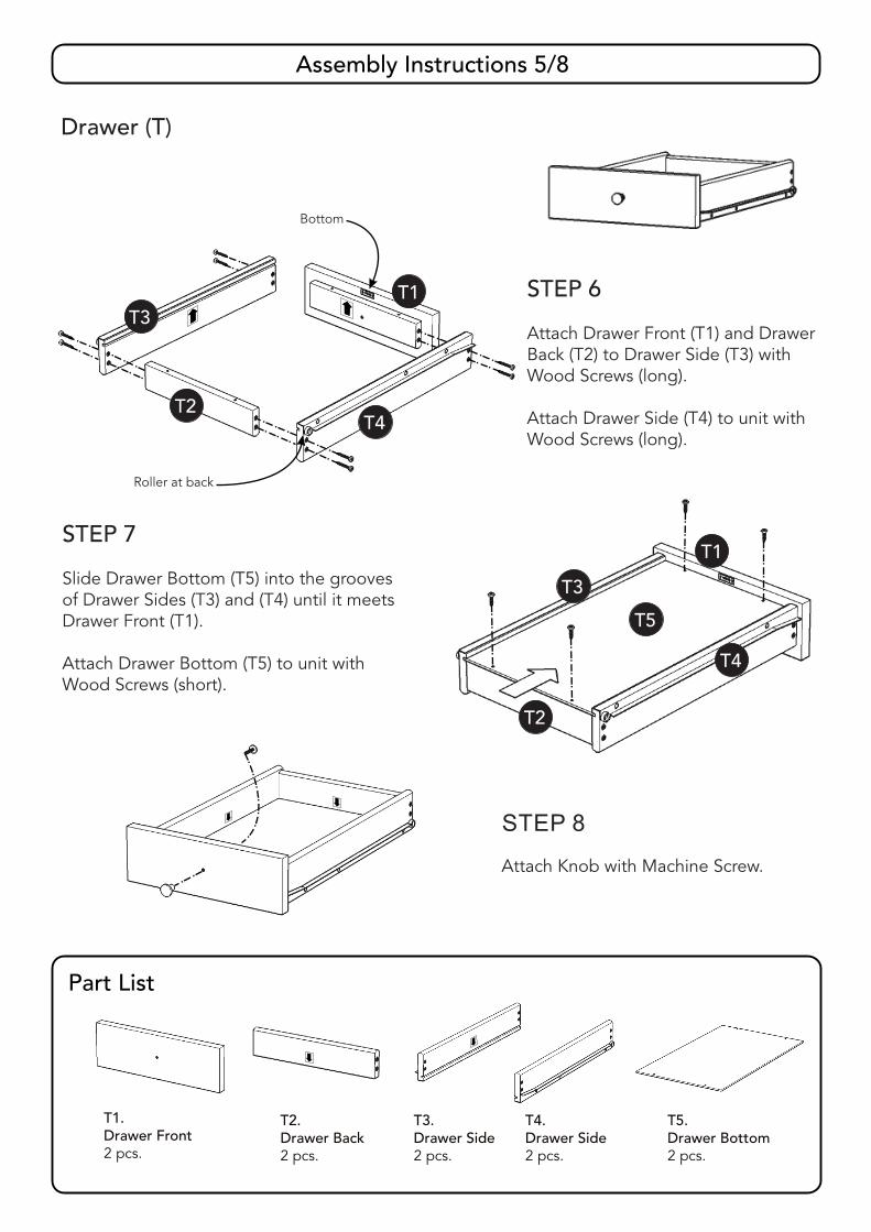
Assembly Instructions 5/8
Drawer (T)
STEP 7
Slide Drawer Bottom (T5) into the groovesof Drawer Sides (T3) and (T4) until it meetsDrawer Front (T1).
Attach Drawer Bottom (T5) to unit withWood Screws (short).
STEP 8
Attach Knob with Machine Screw.
T1.Drawer Front2 pcs.
T2.Drawer Back2 pcs.
T3.Drawer Side2 pcs.
T4.Drawer Side2 pcs.
T5.Drawer Bottom2 pcs.
T1
T2
T3
T4
T5
STEP 6
Attach Drawer Front (T1) and DrawerBack (T2) to Drawer Side (T3) withWood Screws (long).
Attach Drawer Side (T4) to unit withWood Screws (long).
T1
T2
T3
T4
Roller at back
Bottom
Part List
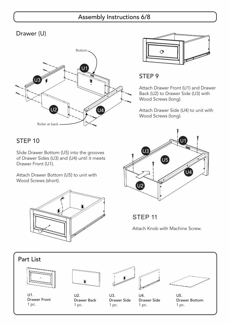
Assembly Instructions 6/8
Drawer (U)
STEP 9
Attach Drawer Front (U1) and DrawerBack (U2) to Drawer Side (U3) withWood Screws (long).
Attach Drawer Side (U4) to unit withWood Screws (long).
STEP 10
Slide Drawer Bottom (U5) into the groovesof Drawer Sides (U3) and (U4) until it meetsDrawer Front (U1).
Attach Drawer Bottom (U5) to unit withWood Screws (short).
STEP 11
Attach Knob with Machine Screw.
U1.Drawer Front1 pc.
U2.Drawer Back1 pc.
U3.Drawer Side1 pc.
U4.Drawer Side1 pc.
U5.Drawer Bottom1 pc.
U1
U2
U3
U4
U5
U1
U2
U3
U4
Roller at back
Bottom
Part List
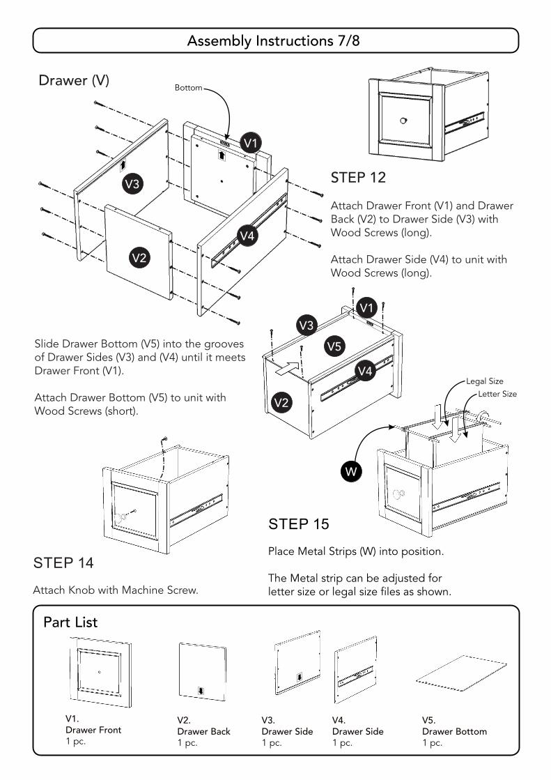
Assembly Instructions 7/8
STEP 14
Attach Knob with Machine Screw.
V1.Drawer Front1 pc.
V2.Drawer Back1 pc.
V3.Drawer Side1 pc.
V4.Drawer Side1 pc.
V5.Drawer Bottom1 pc.
STEP 15
Place Metal Strips (W) into position.
The Metal strip can be adjusted forletter size or legal size files as shown.
STEP 13
Slide Drawer Bottom (V5) into the groovesof Drawer Sides (V3) and (V4) until it meetsDrawer Front (V1).
Attach Drawer Bottom (V5) to unit withWood Screws (short).
Drawer (V)
V1
V2
V3
V4
STEP 12
Attach Drawer Front (V1) and DrawerBack (V2) to Drawer Side (V3) withWood Screws (long).
Attach Drawer Side (V4) to unit withWood Screws (long).
Bottom
Legal Size
Letter Size
W
V1
V2
V3
V4
V5

Assembly Instructions 8/8
Figure 7 Figure 8 Figure 9
T
T
U
V
S
R
Adjustable Pin
STEP 16
Insert Adjustable Pins into side panels at the desired level. (See Figure 7)
Place Shelf (R) into position.
Attach Knob to Door (S) with Machine Screw. (See Figure 8)
Attach Door (S) to unit by sliding the door lift hinges into the side panel lift hinges.(See Figure 9)
Slide Drawers (T), (U) and (V) into position.
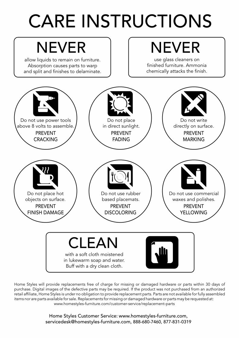
NEVERuse glass cleaners on
finished furniture. Ammoniachemically attacks the finish.
allow liquids to remain on furniture.Absorption causes parts to warp
and split and finishes to delaminate.
NEVER
CARE INSTRUCTIONS
Do not use rubberbased placemats.
PREVENTDISCOLORING
Do not use commercialwaxes and polishes.
PREVENTYELLOWING
Do not place hotobjects on surface.
PREVENTFINISH DAMAGE
Do not writedirectly on surface.
PREVENTMARKING
Do not use power toolsabove 8 volts to assemble.
PREVENTCRACKING
Do not placein direct sunlight.
PREVENTFADING
with a soft cloth moistenedin lukewarm soap and water.Buff with a dry clean cloth.
CLEAN
Home Styles will provide replacements free of charge for missing or damaged hardware or parts within 30 days ofpurchase. Digital images of the defective parts may be required. If the product was not purchased from an authorizedretail affiliate, Home Styles is under no obligation to provide replacement parts. Parts are not available for fully assembleditems nor are parts available for sale. Replacements for missing or damaged hardware or parts may be requested at:
www.homestyles-furniture.com/customer-service/replacement-parts
Home Styles Customer Service: www.homestyles-furniture.com,[email protected], 888-680-7460, 877-831-0319