hcldslam-an digital subscriber line access...
TRANSCRIPT

Digital Subscriber Line AccessMultiplexer Line Card
Application Note
PreliminaryVersion 1.2
HCLDSLAM-AN/D
F
ree
sca
le S
em
ico
nd
uc
tor,
I
For More Information On This Product, Go to: www.freescale.com
nc
...

DSLAM Application Note
Page 2 / 81
Table of Contents
1 Modification History .................................................................................................................32 Overview..................................................................................................................................33 Definitions, Acronyms and Abbreviations................................................................................64 Related Documents .................................................................................................................75 Application Mapping ................................................................................................................86 Assumptions ............................................................................................................................97 Network processor architecture.............................................................................................10
7.1 Data Paths ............................................................................................................................108 Network processor components ............................................................................................13
8.1 XP .........................................................................................................................................138.2 OAM Processing...................................................................................................................148.3 Statistics Management .........................................................................................................158.4 DSL Rx-Tx (CP0-CP3)..........................................................................................................178.5 OC-3c ATM/FR CP (CP4-CP7) ............................................................................................278.6 IPv4 (CP12 & CP14).............................................................................................................328.7 Segmentation (CP8 & CP10)................................................................................................388.8 Reassembly (CP9 & CP11) ..................................................................................................428.9 FR processing – switching (CP13 & CP15)..........................................................................488.10 Fabric Port ..........................................................................................................................518.11 Table Lookup Unit...............................................................................................................538.12 Buffer Management Unit.....................................................................................................578.13 Queue Management Unit ...................................................................................................578.14 Q-3 configurations for CPs, XP and FP..............................................................................58
9 HOST PROCESSOR ARCHITECTURE ...............................................................................6010 HOST PACKET I/O................................................................................................................61
10.1 Resources...........................................................................................................................6110.2 Packet Reception................................................................................................................6110.3 Packet Transmission ..........................................................................................................62
11 CONSOLE COMMAND SHELL COMMANDS ......................................................................6211.1 Application Control..............................................................................................................6211.2 Table Maintenance and Display .........................................................................................6211.3 DSL Link Configuration and Status ....................................................................................6311.4 OC-3c interface Configuration and Status..........................................................................6311.5 ATM Configuration and Status ...........................................................................................6311.6 FR Configuration and Status ..............................................................................................6411.7 Statistics .............................................................................................................................64
12 HOST PROCESSOR TO NETWORK PROCESSOR INTERFACE .....................................6412.1 FR .......................................................................................................................................65
13 HOST API REFERENCE.......................................................................................................6513.1 Table API ............................................................................................................................6513.2 Link and Channel API.........................................................................................................7513.3 ATM API .............................................................................................................................7513.4 FR API ................................................................................................................................7713.5 Control API .........................................................................................................................7813.6 I/O API ................................................................................................................................80
14 Appendix – Optimizations done in the application................................................................81
F
ree
sca
le S
em
ico
nd
uc
tor,
I
Freescale Semiconductor, Inc.
For More Information On This Product, Go to: www.freescale.com
nc
...

DSLAM Application Note
Page 3 / 81
1 Modification HistoryRev Date Author Department Changes1.0 24-Feb-03 HCL Technologies Networking Initial version.1.1 12-Mar-03 J.Bednarek Freescale/C-Port First Comments.1.2 13-Mar-03 HCL Technologies Networking Incorporated review
comments from Freescale
2 OverviewThis document aims at discussing the design of a Digital Subscriber Line AccessMultiplexer (DSLAM) line card. The intended audiences of this document are thesoftware designers, testers and programmers of the line card based on the C-Portnetwork processor family.
The reader of this document is expected to have a fair understanding of the C-3e NParchitecture and the associated co-processor such as Q-3 (Traffic Management Co-processor) with the basic understanding of M-2 Utopia/POS-PHY Adapter ReferenceDesign used in the design of the DSLAM line card.
Feature Overview and Standards Support
This application supports the following features:• A maximum of 192 ports of ADSL ports• Support for upto 9 Mbps downstream traffic and 1 Mbps upstream traffic per DSL
port/channel.• OC-3c interfaces running ATM / FR over SONET• FR header processing and reassembly• AAL5 segmentation and reassembly• ATM Cell switching• FR switching• IPv4 Unicast Routing on all interfaces (ATM/FR)• Support for ATM traffic management
DSLAM line card is intended to work in a stack of cards connected on the switchingfabric for communication with the other DSLAM cards as well as the line cards thatterminate ATMs. The host module manages and maintains the statistics for the entiresystem. The communication of the host with the line cards is through the PCI interface.Figure 1 helps in understanding this configuration of the DSLAM line card.
Figure 2 and Figure 3 show two configurations of DSLAM application for which thedesign has been implemented.
F
ree
sca
le S
em
ico
nd
uc
tor,
I
Freescale Semiconductor, Inc.
For More Information On This Product, Go to: www.freescale.com
nc
...

DSLAM Application Note
Page 4 / 81
PCI busHost Processor
card
SwitchingFabric
DSLAMLine card 192 ADSL
Interfaces• • •• • •
ATM / FRInterfaces
ATM / FRLine Card
• • •
Figure 1: Stackable DSLAM line cards within a system
F
ree
sca
le S
em
ico
nd
uc
tor,
I
Freescale Semiconductor, Inc.
For More Information On This Product, Go to: www.freescale.com
nc
...

DSLAM Application Note
Page 5 / 81
Configuration I (Figure 2) comprises of eight 24 port xDSL chipset supporting 192 ADSLports in total. This configuration implements a switch fabric interface. The chunksreceived on DSL interfaces are sent across the fabric interface via FP.
HostprocessorCard
Q-3 TrafficManagementco-processor
Cluster- 0
Cluster- 1
Cluster- 2
Cluster- 3
QMU
TLU
BMU
XP
FP
C-3e
PCISwitchingFabric
M2Quad
192 ADSL Ports
• • •• • •• • •• • •
24 DSL
24 DSL
24 DSL
24 DSL
M2Quad • • •
• • •• • •• • •
24 DSL
24 DSL
24 DSL
24 DSL
Figure 2: Configuration- I DSLAM line card with 192 ADSL ports
Configuration II (figure 3) is comprised of 96 DSL ports. This configuration implementsan uplink of four OC-3c interfaces. It does not have a switch fabric interface.
M2 QuadPOS-PHYAdapter
Host processor
C-3eNetwork
processor
Q-3 TrafficManagementco-processor
96 ADSL Ports
• • •• • •• • •• • •
24 DSL
24 DSL
24 DSL
24 DSL
S3029Quad
Transceiver
4 OC-3c interfacesrunning ATM / FR
over SONET
Figure 3: Configuration- II Independent DSLAM unit
F
ree
sca
le S
em
ico
nd
uc
tor,
I
Freescale Semiconductor, Inc.
For More Information On This Product, Go to: www.freescale.com
nc
...

DSLAM Application Note
Page 6 / 81
3 Definitions, Acronyms and Abbreviations
AAL ATM Adaptation LayerATM Asynchronous Transfer ModeATM TM ATM Traffic ManagementBE Best effortBOM Beginning of Message.CA Channel AdapterCBR Constant Bit RateCID Channel IDCIDR Classless Inter Domain RoutingCPI Common Part Indicator.CPRC Channel Processor RISC core.CRC Cyclic Redundancy Check.DLCI Data Link Connection IdentifierDWRR Dynamic Weighted Round RobinFR Frame RelayHEC Header Error Control.HTK Hash Trie Key.ICMP Internet Control Message ProtocolIP Internet ProtocolLCP Link Control ProtocolLLC Logical Link ControlLMI Local Management InterfaceLPM Longest Prefix Match.LSP Label switched pathMIB Management Information BlockMPHY Multi PHYMTU Maximum transmission UnitNCP Network Control ProtocolNLPID Network Layer Protocol IDOAM Operation, Administration and Maintenance.PDU Protocol Data Unit.PPP Point to Point ProtocolQoS Quality Of ServiceRED Random Early DiscardRM Resource Management.RR Round RobinSDU Service Data Unit.SNAP Subnetwork Access Protocol.SPHY Single PHYTCP Transport Control Protocol
Abbreviation Description
F
ree
sca
le S
em
ico
nd
uc
tor,
I
Freescale Semiconductor, Inc.
For More Information On This Product, Go to: www.freescale.com
nc
...

DSLAM Application Note
Page 7 / 81
TLU Table Lookup Unit.TMC Traffic Management Co-ProcessorTOS Type of ServiceTTL Time To LiveUUI User-to-User Interface.VC ATM Virtual ConnectionVOP Virtual Output PortVP ATM Virtual PathVPCI Virtual Path Identifier/Virtual Channel IdentifierWFQ Weighted Fair queueing
4 Related DocumentsThis section lists down the various documents used as reference while developing thisapplication notes.• C-5e/C-3e Network Processor Silicon Revision A0• Multi-PHY Switch Application Guide, CST2.2• POS to Gigabit Ethernet Switch application guide CST 2.2• ATM Cell Switch Application Guide, CST 2.1.1• RFC 791, Internet Protocol• RFC 1812, Requirements for IP Version 4 Routers• RFC 2427, Multiprotocol Interconnect over Frame Relay• RFC 2684, Multi Protocol Encapsulation over ATM Adaptation Layer 5• ITU I.361, B-ISDN ATM Layer Specification• ITU I.363.5, B-ISDN ATM Adaptation Layer Specification: Type 5 AAL• ITU I.610 B-ISDN Operation and Maintenance Principles and Functions• Frame Relay to ATM to 10/100 Ethernet Switch Router Application Guide, CST2.1• C-ware Q-5 TMC API User guide Rev 00
Abbreviation Description
F
ree
sca
le S
em
ico
nd
uc
tor,
I
Freescale Semiconductor, Inc.
For More Information On This Product, Go to: www.freescale.com
nc
...

DSLAM Application Note
Page 8 / 81
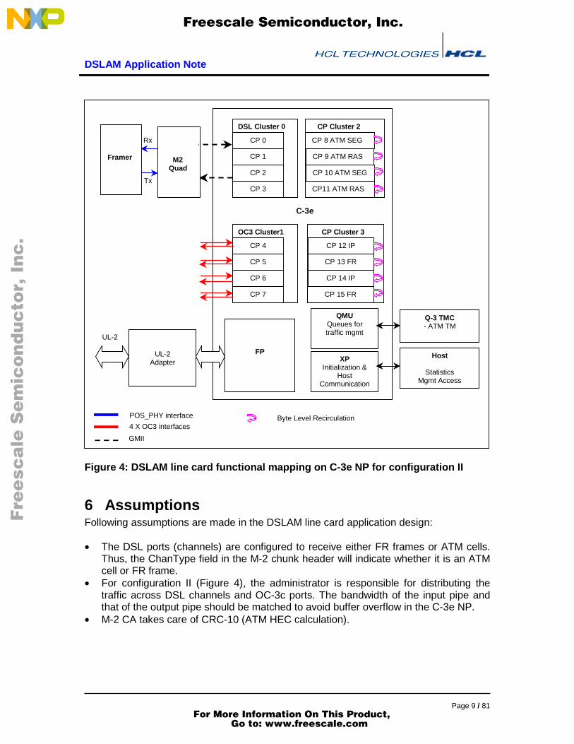
5 Application MappingThis application is comprised of many software components, each of which is dividedinto smaller components. The functional partitioning of the software is depicted in figure4 with the clustering and re-circulation information. C-3e NP is chosen for implementingthe DSLAM line card as the processing power of the NP and the M-2 Quad match andQ-3 is used for managing the traffic management for IP and ATM.
Figure 4 shows the DSLAM card functioning in a C-3e for configuration II (shown infigure 3).In this configuration, the CP allocation is as follows:
• Cluster 0 (CP0-3) connected to M-2 Quad which in turn connected to four G-24chip. It implements the MPHY interface.
• Cluster 1 (CP4-7) is connected to four OC-3c links• CP8 and CP10 for AAL-5 segmentation• CP9 and CP11 for AAL-5 reassembly• CP12 and CP14 for IP processing• CP13 and CP15 for FR switching and processing
CP8 and CP9 perform segmentation and reassembly, respectively, for the M-2 MPHYchunks received at DSL cluster (cluster 0). While CP10 and CP11 are for packetsreceived at OC-3c cluster. Similarly, CP12 and CP13 do IP and FR processing,respectively, for M-2 MPHY chunks received at DSL cluster. Packets received at OC-3cinterfaces will be queued to CP14 and CP15 for IP and FR processing. Appendix statesthe reason for this distribution of traffic.
The functional mapping of DSLAM card for configuration I will be same as figure 4except for the OC-3c cluster. Cluster1 will be connected to another M-2 Quad forprocessing frames coming from another set of 96 ADSL ports. Other CP allocation issame in configuration I (Figure 2).
The following sections in the document explain the functionality specific to configurationII. For configuration I, DSL-cluster functionality will override the OC-3c clusterfunctionality.
F
ree
sca
le S
em
ico
nd
uc
tor,
I
Freescale Semiconductor, Inc.
For More Information On This Product, Go to: www.freescale.com
nc
...
DSLAM Application Note
Page 9 / 81
CP 12 IP
CP 13 FR
CP 14 IP
CP 15 FR
CP Cluster 3
FPXP
Initialization &Host
Communication
CP 8 ATM SEG
CP 9 ATM RAS
CP 10 ATM SEG
CP11 ATM RAS
CP Cluster 2
CP 4
CP 5
CP 6
CP 7
OC3 Cluster1
DSL Cluster 0
CP 0
CP 1
CP 2
CP 3
Host
StatisticsMgmt Access
UL-2
UL-2Adapter
C-3e
Q-3 TMC- ATM TM
QMUQueues fortraffic mgmt
Byte Level Recirculation
Rx
Tx
Framer M2Quad
4 X OC3 interfaces
POS_PHY interface
GMII
Figure 4: DSLAM line card functional mapping on C-3e NP for configuration II
6 AssumptionsFollowing assumptions are made in the DSLAM line card application design:
• The DSL ports (channels) are configured to receive either FR frames or ATM cells.Thus, the ChanType field in the M-2 chunk header will indicate whether it is an ATMcell or FR frame.
• For configuration II (Figure 4), the administrator is responsible for distributing thetraffic across DSL channels and OC-3c ports. The bandwidth of the input pipe andthat of the output pipe should be matched to avoid buffer overflow in the C-3e NP.
• M-2 CA takes care of CRC-10 (ATM HEC calculation).
F
ree
sca
le S
em
ico
nd
uc
tor,
I
Freescale Semiconductor, Inc.
For More Information On This Product, Go to: www.freescale.com
nc
...

DSLAM Application Note
Page 10 / 81
7 Network processor architectureThe DSLAM application consists of many software components. One componentexecutes on the host and the other components execute on the various CPs within theC-3e. Each of the NP software components provides a subset of the features of theapplication. Figure 4 shows the mapping between software components and CPs. Thedata paths between these components can be conceptualized as a group of busses. Inthis context, a bus is the combined use of queues and buffer memory to forward databetween two components. The queue number is analogous to the address on the bus.Each of the buses implies a different buffer and descriptor format (for ATM, FR, IP andso on). The traffic originating from DSL ports/channels will be either ATM or FR basedon the channel configration.
A buffer and a buffer descriptor can specify the interface to a component. Table belowlists each of the components and describes their interface. A component may havemultiple interfaces and therefore multiple entries in the table. Unless specified otherwisein the table, the port field indicates the output port and the length field indicates thenumber of bytes in the buffer. The various buffer formats are described in section BufferManagement Unit and the buffer descriptor formats are described in appropriatesections.
Component Buffer Format Descriptorformat
Comments
IP BT_IPV4 N/A Port indicates input port; IPforwarding will be performed
FR BT_FR FRSegmentation BT_IPV4 Seg EgressQueue field is
required.Reassembly BT_ATM ATM Port indicates input port;
AAL-5 reassembly will beperformed
UL-2 BT_ATM ATMBT_ATM ATM Port indicates the input port;
only header field requiredHost
All others N/A Port indicates the input port
7.1 Data PathsThis section explains about various data paths originating from DSL port interfaces andflowing through other components in the NP. M-2 is the channel adapter for the DSLAMapplication. Figure 5 shows the diagrammatic representation of the data flows.
F
ree
sca
le S
em
ico
nd
uc
tor,
I
Freescale Semiconductor, Inc.
For More Information On This Product, Go to: www.freescale.com
nc
...

DSLAM Application Note
Page 11 / 81
Figure 5: Data Flows in the DSLAM Application
F
ree
sca
le S
em
ico
nd
uc
tor,
I
Freescale Semiconductor, Inc.
For More Information On This Product, Go to: www.freescale.com
nc
...

DSLAM Application Note
Page 12 / 81
7.1.1 Data Path for FR FramesThis section conceptualizes the data flows for FR frames. FR Frames are received inDSL Rx. The FR chunks will be reassembled as FR frame in the Rx, recirculated in othercomponent CPs and finally transmitted as FR or AAL5 chunks via DSL Tx or OC-3cinterfaces.
• FR frame is received as M-2 MPHY chunks in DSL Rx, are reassembled andidentified as FR frame based on the DSL channel configuration. Then it will beenqueued to FR queue for further FR processing.
• FR component CP performs the DLCI lookup. Based on lookup response, it willenqueue the frame to IP queue or does FR switching (modify the FR header withnew DLCI value) and enqueue into appropriate DSL Tx queue.
• IP component dequeues the FR frame from its queue, removes the FR headerand enqueues the IP packet into destination queue (FR queue or ATMSegmentation queue) determined by IP lookup and port lookup result.
• ATM segmentation component will segment the IP packet into AAL5 cells, insertsthe ATM header and enqueues these cells to appropriate Tx queue or to Q-3traffic queue.
• DSL Tx dequeues the FR frame or ATM cells from its queue. It transmits MPHYchunks over DSL links. For ATM, each cell will fit into one MPHY chunk. For FR,it segments the frame into multiple MPHY chunks.
• If QoS treatment is needed, packets will be enqueued to Q-3 traffic queue fromATM Segmentation for applying various QoS parameters. Q-3 TMC providesmarking/dropping, policing and traffic shaping for the packet based on configuredtraffic parameters. Q-3 TMC will enqueue the conformant packets into QMUqueue. Non-conformant packets will either be discarded or marked.
7.1.2 Data Path for ATM cellsThis section describes the data flow for ATM cells. The ATM cells are received in DSLRx or OC-3c interfaces. The ATM cells will be recirculated in other component CPs andfinally transmitted as FR / AAL5 chunks via DSL Tx or ATM cells in OC-3c intetfaces.
• ATM cells will be enqueued to DSL Tx queue or OC-3c Tx queue (ATMswitching) or FP queue.
• AAL5 cells are enqueued into reassembly queue by DSL Rx that performs theVC table lookup to send the new VPI/VCI values into the reassembly queue.
• ATM reassembly component will de-queue and reassembles the cells into AAL5PDU. It will then be enqueued into IP queue.
• IP component dequeues the reassembled AAL5 PDU from its queue, enqueues itinto destination queue (DSL Tx queue or OC-3c Tx queue or ATM Segmentationqueue) determined by IP lookup and port lookup result.
• ATM segmentation component will segment the IP packet into AAL5 cells,modifies the AAL5 header (with new VPI/VCI) and enqueues these cells to DSLTx queue or to OC-3c queue or to Q-3 traffic queue (if QoS is needed).
• DSL Tx dequeues the FR frame or AAL5 cells from its queue. It transmits MPHYchunks. For ATM, each cell will fit into one MPHY chunk. For FR, it segments theframe into MPHY chunks.
F
ree
sca
le S
em
ico
nd
uc
tor,
I
Freescale Semiconductor, Inc.
For More Information On This Product, Go to: www.freescale.com
nc
...

DSLAM Application Note
Page 13 / 81
• OC-3c Tx dequeues the ATM cells and transmits them over the line.• If QoS is needed, packets will be enqueued to Q-3 traffic queue from ATM
Segmentation for applying various QoS parameters. Q-3 TMC providesmarking/dropping, policing and traffic shaping for the packet based on configuredtraffic parameters. Q-3 TMC will en-queue the conformant packets into QMUqueue. Non-conformant packets will be discarded.
8 Network processor componentsThis section describes each of the features of the applications in detail and explains howeach component or resource within the NP is used to provide the applications’ features.
The Executive Processor RISC Core (XPRC) is a general-purpose processor thatprovides management, control, and exception processing functions. The XP controls NPboot up, configuration, and initialization of all system components.
The Channel Processors (CPs) are the components most closely associated withprocessing data from a physical interface. There are 16 CPs organized as four clusters,each of which contains four CPs. Each cluster performs several functions that aid in theprocessing of data packets.
8.1 XPThe XP program is partitioned into distinct ‘initialization’ and ‘main’ executables. Afterloading and running the initialization executable, the main executable is loaded andoverlayed on the initialization executable, reducing the IMEM used at run-time. Thispartitioning scheme uses the available IMEM resource to its fullest.
8.1.1 Initialization ProgramThe initialization executable performs service initialization, configures system resources,and loads the CPs. In particular, the initialization executable does the following:
• Allocates buffer pools.• Allocates and configures queues.• Configures the fabric port• Configures the PHY interfaces• Loads the CPs• Defers to the main XP executable program
8.1.2 Main ProgramThe main executable completes any necessary initialization and starts the CPs beforeentering the main loop. In particular, the main executable does the following:
• Initializes the CRC correction table• Starts the CPs and enables the fabric port.• Starts some of the SDPs• Initializes the OAM processing component
F
ree
sca
le S
em
ico
nd
uc
tor,
I
Freescale Semiconductor, Inc.
For More Information On This Product, Go to: www.freescale.com
nc
...

DSLAM Application Note
Page 14 / 81
• Initializes the host communication component• Enters the main loop
The main loop within the XP performs processing for OAM handling described in section“OAM processing” and host communication for updating statistics.
8.2 OAM ProcessingOAM cells received by the DSL CPs or OC-3c CPs are forwarded to the XP forprocessing. OAM support in the application includes the following:
• Forward Performance Monitoring – Receive Monitoringo Blocks of user cells on a limited number of VCCs (128) are monitored for
errors per flow. A BIP-16 is generated for all the cell payloads for eachblock where the block size is configurable. The block size is defaulted to128 cells.
o The receiver checks the parity on the received block data and comparesits results with the received BIP-16. The number of errors is determinedand written to a statistics counter for the indicated VC.
OAM processing uses the ATM VC table.
8.2.1 SDPThe DSL and OC-3c CPs support OAM performance monitoring. The SDP processorson the CPs do the following:
8.2.1.1 RxSyncThe RxSync processor performs the following OAM functions:
• Determines the CRC-10 for each cell received (regardless of whether the cell isOAM or not) and forwards a pass-fail notification to the RxByte processor.
RxSync is not configurable through its control space.
8.2.1.2 RxByteThe RxByte processor performs the following OAM functions:
• Determines whether an F4/F5 OAM cell has been received and indicates this inextract space
• Writes cell payload overhead to extract space.• Forwards CRC-10 pass/fail indication to the RC through extract space• Determines the BIP-16 value on each cell received and writes this value to
extract space.• Determines whether a user cell has been received and writes this information to
extract space
8.2.2 RCThe RC performs higher level processing of data packets to support OAM –FPM.
F
ree
sca
le S
em
ico
nd
uc
tor,
I
Freescale Semiconductor, Inc.
For More Information On This Product, Go to: www.freescale.com
nc
...

DSLAM Application Note
Page 15 / 81
8.2.2.1 InitializationDuring initialization, the 128 entry OAM PM table is initialized.
8.2.2.2 ReceiveThe receive thread handles incoming data packets and performs OAM specificoperations. Specifically, it does the following:
• Checks whether a received cell is on a VC where OAM FPM is being performed.This information is stored in the ATM VC table (the oamPm field). If this cell is auser cell, it does the following:
o XORs the current value of the BIP-16 into OAM FPM table running totalfor all user cells.
o Increments and masks the CurrentBlockValue (ranges from 0 toBlockSize-1).
• If the received cell is not a user cell, then the code checks whether an OAM cellhas been received. If OAM but not of the type OAM FPM cell, the cell isforwarded to the XP. Otherwise, it does the following:
o Compares the CurrentBip16 value with the value received in the OAMFPM Cell. If these values are XOR-ed, the number of bits set indicatesthe number of errors. The number of bits set is determined through alookup into a 16-byte table (where each byte in the table indicates thenumber of bits set for the index) for each nibble (oamPmErrTab). Theinformation is used to update TotalBip16Errs counter.
8.2.3 Data Structures
8.2.3.1 OamPmTableThis OAM processor maintains OAM performance monitoring state information in thefollowing data structure:
Bytes 0 1 2 30 TotalBip16Errs CurrentBlockValue4 CurrentBip16 BlockSize8 SeqnumExpect Pad
• totalBip16Errs – count of BIP-16 errors calculated so far• currentBlockValue – the number of the cell in the current block• currentBip16 – the value of the BIP-16 calculated so far• blockSize – the block size (in cells)• seqNumExpect – the expected sequence number to be received• pad – unused
8.3 Statistics ManagementXPRC maintains all the statistics for the DSLAM applications. It passes the statisticsstorage pointer to the CP’s at initialization. CPs update the statistics maintained in XPs
F
ree
sca
le S
em
ico
nd
uc
tor,
I
Freescale Semiconductor, Inc.
For More Information On This Product, Go to: www.freescale.com
nc
...

DSLAM Application Note
Page 16 / 81
at run time. Host reads the statistics from XPs DMEM, needed by statistics consolecommand.
For each DSL link, either ATM or FR statistics are maintained. IP statistics are alsomaintained for each DSL links. Given below are list of statistic fields for ATM, FR and IP.
List of ATM statistics:
• rxGoodCells - Number of received ATM Cells• rxOamCells - Number of received ATM OAM Cells• enqueueFail - Number of times enqueue failed• txCells - Number of transmitted ATM Cells• txOamCells; - Number of transmitted ATM OAM Cells• rxCongestDrops - Number of ATM Cells dropped due to congestion• rxHecErrored - Number of ATM Cells having HEC errors• rxInvalidVc - Number of ATM Cells having invalid VCs
List of FR statistics:
• RxGoodFrames - Number of received FR frames.• EnqueueFail - Number of times enqueue failed• TxFrames - Number of transmitted FR frames.• CongestDrops - Number of FR frames dropped due to congestion• InvalidDlci - Number of FR frames having invalid DLCI• FcsError - Number of FR frames having FCS errors• EncapCntrlErr - Number of FR frames having invalid control field• EncapNlpidErr - Number of FR frames having invalid NLPID• FrReservedDlci- Number of FR frames having reserved DLCI value.
List of IP statistics:
• IpInReceives - Total number packets received in IP module• IpInHdrErrors - The number of input datagrams discarded due to errors in their IP
headers.• IpForwDatagrams - Number of input datagrams forwarded• IpOutPayloadErrors - Number of packets discarded due to payload errors• IpOutInvalidPortErrors - Number of packets discarded because its route entry
mapped to an invalid egress port.• IpOutNoRoutes - Number of IP datagrams discarded because no route could be
found to transmit them to their destination
XP needs 11.25 KB DMEM to support ATM/FR and IP statistics for a maximum of 192DSL links.
F
ree
sca
le S
em
ico
nd
uc
tor,
I
Freescale Semiconductor, Inc.
For More Information On This Product, Go to: www.freescale.com
nc
...

DSLAM Application Note
Page 17 / 81
8.4 DSL Rx-Tx (CP0-CP3)CP0 to CP3 implement the MPHY interface receive processing and ATM processing forADSL ports. CPs in this cluster receive and transmit MPHY chunks through M-2 Quad.The processing is divided into various components of the CPs. It is explained as follows:
8.4.1 SDP
8.4.1.1 RxBitRxBit waits for a transition of the PhyStatus0 signal to indicate valid data and the start ofa chunk. RxBit is responsible for coordinating ingress processing within the cluster. Fordoing this, it utilizes a token to determine which bit processor should forward its datastream. The processors without the token simply sink the data stream until thePhyStatus0 signal indicates that data is no longer valid. They then return to waiting for itto indicate valid data again.The processor owning the token, streams the first byte of data, passes the token, andthen streams the data-stream to the RxSync processor until the PhyStatus0 signalindicates that data is no longer valid. The processor then sends an EOF marker withMerge9 set and a frame status value. Currently there are no errors detected by the RxBitprocessor and it always sends a frame status value indicating success. The processingthen returns to waiting for PhyStatus0 to indicate valid data again.
The RxBit processor does not currently use any control space information from theCPRC.
8.4.1.2 RxSync
FR RxSync:RxSync processor is not used for FR frames, it simply streams all data received to theRxByte processor.
ATM RxSync:RxSync accumulates CRC-10 and forwards all the cells to RxByte along with CRC-10flag. This flag eventually makes its way to CP, which will discard all errored cells.
8.4.1.3 RxByteATM RxByte:
For ATM cells, RxByte performs the following functions:• Processes M-2 CA Header. It strips off the sequence number and frame length
from the M-2 header and write them to extract space.• Pushes the VPI, VCI, and DSL channel ID through a shift and mask function that
produces a Virtual Channel (VC) Index.• Issues a ATM VPI/VCI lookup request to the TLU.• It then writes the following fields into Extract Space:
o Payload Type Indicator (PTI) and Cell Loss Priority (CLP)o Generic Flow Control (GFC)o VPIo VCI
F
ree
sca
le S
em
ico
nd
uc
tor,
I
Freescale Semiconductor, Inc.
For More Information On This Product, Go to: www.freescale.com
nc
...

DSLAM Application Note
Page 18 / 81
o Encoded PTI (an internal representation of the “type” of cell such as Useror OAM)
• Maintains congestion drop count (that is, how many intermediate cells weredropped)
• The remainder of the frame is streamed using a 4-byte deep pipeline. Thepipeline is used to avoid streaming the 3 bytes of M-2 CA trailer and the 1byteframe status from RxBit.
• Verifies CRC-10 and places result into extract space
FR RxByte:
For FR frames, RxByte performs following activities:• At the beginning of processing, the RxByte reports a count of any frames
dropped by RxByte due to CPRC unavailability (i.e., CPRC hadn’t released ascope yet)
• Waits for valid data. Simply monitors the FIFO from RxSync for valid data bytes.• Processes M-2 CA Header. Strips off the sequence number and frame length
from the M-2 header and writes them to extract space.• Reads the chunk type and channel type into extract space• For SOP FR chunk, first five bytes of FR header will be fetched into extract
space. These bytes contain address, control, DLCI field and NLPID value of theheader. It then sets L1 done for RxCPRC and sends the remaining bytes ofpayload of the chunk to DMEM.
• The protocol field is checked for IP protocol. If it is not IP, a frame status ofUnknown Protocol is written to extract space and the rest of the frame is simplystreamed to the buffer and not parsed.
• For non-SOP M-2 chunk, it sets L1 done for RxCPRC and sends the remainingbytes of payload of the chunk to DMEM.
• When data9 is received, it writes the chunk status code to extract space andswitches scope.
• Streams the payload. The remainder of the frame is streamed using a 4bytedeep pipeline. The pipeline is used to avoid streaming the 3bytes of M-2 CAtrailer and the 1byte frame status from RxBit.
• Checks Status Bytes. The status bytes from RxBit and the M-2 CA are processedand the frame status in extract space is updated with any errors indicated. Ifthere are any errors indicated, the CRC check will not be performed.
• Checks CRC. RxByte feeds the incoming stream through a CRC accumulator asit is processing the frame. After it has fed the CRC field from the M-2 CA trailerthrough the accumulator, the value of the accumulator is checked to determine ifthere has been any data corruption. Note, the status byte from RxBit should notbe fed through the CRC accumulator. If any CRC errors are detected, the framestatus in extract space will be updated to reflect the error.
• In order to ensure that the final byte streamed to the buffer has been written,RxByte must delay 10 clocks after the last byte was streamed before switchingscope to give the DMA time to complete the action.
• RxByte now switches to the other scope and checks whether the CPRC hasreleased it yet. If the CPRC has already released the new scope RxByte starts
F
ree
sca
le S
em
ico
nd
uc
tor,
I
Freescale Semiconductor, Inc.
For More Information On This Product, Go to: www.freescale.com
nc
...

DSLAM Application Note
Page 19 / 81
over with the Report Dropped Frames step. Otherwise, it continues with the nextstep.
• Waits for scope ownership. While RxByte is waiting for the CPRC to release ascope, it continues to read any incoming data on the FIFO and discards the bytesread. It keeps track of how many frames are received in the discarded data andreported the count to the CPRC when scope is available.
8.4.1.4 TxByteThe major activities of the TxByte processor are to transmit the M-2 CA header and thetrailer bytes. Each activity is described below:
• M-2 CA Header: TxByte generates and outputs the sequence number and framelength fields of the M-2 header based on data from merge space.
• M-2 CA Trailer: TxByte generates and outputs a status field indicating a goodframe and outputs the CRC-16 field based on the value read from the CRCaccumulator.
The TxByte processing can be broken down into the following sequential steps:
FR TxByte:• TxByte waits for valid data to appear in the FIFO from the CPRC.• Once valid data is present, it initializes the CRC accumulator and begins
processing the data. All data bytes output by the processing will also run throughthe CRC accumulator.
• It generates and outputs the sequence number and frame length fields of the M-2header based on data from merge space.
• Stream bytes from the FIFO until it receives an indication that there is no morevalid data in the FIFO (that is, Data9).
• Generates and outputs a status field indicating a good frame and outputs theCRC field based on the value read from the CRC accumulator.
• Now switches to the other scope of merge space.
ATM TxByte:
After receiving a cell, TxByte process formats the cell and sends it away to large FIFO.Following are the functions preformed by TxByte.
• Merge in ATM header, the information from the merge space. In DSLAMapplication, it does not generate HEC (Header Error Check) because the framertakes care of HEC calculation.
• Passes token by asserting data9• It now streams bytes from the FIFO until it receives an indication that there is no
more valid data in the FIFO (that is, Data9)• CRC10 is appended to the end of the payload that totals 48 bytes.
8.4.1.5 TxBit
• TxBit waits for an indication of valid data in its FIFO. While there is no valid data,it will transmit idle characters to the M-2 CA. It does not matter what character is
F
ree
sca
le S
em
ico
nd
uc
tor,
I
Freescale Semiconductor, Inc.
For More Information On This Product, Go to: www.freescale.com
nc
...

DSLAM Application Note
Page 20 / 81
used for idle as long as the transmit enable signal (Data9) is not asserted whenthe character is transmitted.
• Once valid data is present in the FIFO, TxBit asserts the transmit enable signaland begins streaming the data from the FIFO to the M-2 CA.
• Once the FIFO is emptied of valid data, the TxBit processor de-asserts thetransmit enable signal.
8.4.2 RCThe RC component uses two threads to perform its task, namely, an input thread and anoutput thread. The initialization code starts the two threads. Each of these is describednext.
8.4.2.1 InitializationThe RC component of DSL CP does the following things during its initialization:
• Creates the input and output threads.• Initializes the ATM and IP route lookups launched by the SDP, for ATM cells and
FR frames, respectively.• Initializes both scopes by giving the SDP ownership• Starts the SDP.• Jumps to the first thread
8.4.2.2 Input ThreadATM Rx:
This component in DSL Rx CP handles ATM cells. Specifically, it does the following:• Waits for ATM VPI/VCI lookup to complete• Lookup failure causes the cell to be dropped and a statistics counter is
incremented.• Allocates new buffer and initiates payload transfer from DMEM to SDRAM.• Builds descriptor with forwarding information from lookup response• Waits for payload transfer to complete.• Determines whether OAM FPM is being performed on this VC. If so:
o For user cells, read the current BIP16 value from extract space and XORwith current value. Update OAM fields.
o For OAM FPM cells, check BIP16 and maintain count of total BIP16errors.
• For cells other than AAL-5, it launches port table lookup.• Waits for port lookup to complete• En-queues descriptor to egress queue or QoS queue indicated by port lookup
result• For AAL-5 cells, the cells are queued to reassembly module
FR Rx:This component in DSL Rx CP handles FR frames. Specifically, it does the following:
• Waits for L1 done so that SDP has completed the header processing and put thenecessary information into extract space.
F
ree
sca
le S
em
ico
nd
uc
tor,
I
Freescale Semiconductor, Inc.
For More Information On This Product, Go to: www.freescale.com
nc
...

DSLAM Application Note
Page 21 / 81
• Makes the pointer (chRxCBPtr) point to DSL Rx Control block in DMEM.ChRxCBPtr will depict the M-2 chunk reassembly information in DMEM.
• Processes chunk based on chunk type (flow control or user) in extract spaceafter checking for errors.
• For SOM chunk,o Allocate new buffer for reassembling the FR chunkso Destination queue will be the FR queue.o Get the FR header information by properly interpreting the extract space.o Write the FR header into DSL Rx channel control block (chRxCBPtr).
• Initiate the payload transfer from DMEM to SDRAM if no error is indicated inchunk. Update the buffer offset in DSL Rx channel control block (chRxCBPtr) byincrementing it with chunk length.
• For non-SOM chunks, retrieve reassembly state information (buffer handle andbuffer offset) from Rx channel control block (chRxCBPtr) and initiate the payloadtransfer from DMEM to SDRAM if no error is indicated in chunk. Also, update thebuffer offset in the control block (chRxCBPtr).
• For EOM chunk, build the descriptor with buffer handle, buffer length and FRheader (DLCI value). En-queue it to the FR queue.
8.4.2.3 Output ThreadThe output thread handles outgoing cells or datagrams. Specifically, it does thefollowing:
• Check channels in a round robin manner for credits available(chFlowChunksAvail).
• Get state information for current channel i.e. get the pointer chTxCBPtr whichpoints to DSL Tx channel control block in DMEM. This control block will containthe segmentation state information.
• If chFlowChunksAvail is true, check whether this channel is in the process ofsegmenting the PDU into M-2 chunks i.e. transmitting the chunks of a PDU. If itis so, the next chunk of PDU will be transmitted.
• If no segmentation is in progress, the incoming descriptor will be de-queuedfrom its queue. Note that the descriptor would have been en-queued by
o FR module (CP13 and CP15- for FR switching)o ATM segmentation (CP8 and CP10)
• After de-queuing, the segmentation state will be updated with the valuesfetched from descriptor. Segmentation state values to be updated are: BufferHandle, Buffer offset, length and port buffer type taken from incomingdescriptor. Offset will be filled as zero
• PortBufferType will be checked to determine the incoming module i.e. fromwhich module it has come (BT_ATM or others) so that it will segment the PDUaccordingly.
• If portBufferType is BT_ATM, it is an ATM cell and hence will be switched. IfportBufferType is other than BT_ATM, the frame needs to be segmented intonumber of chunks based on the channel length in chTxCBPtr.
• For segmenting into chunks, chunk length (1 - 64 bytes) will be calculatedbased on offset in ChTxCBPtr (for first chunk, the offset will be 0). Also if chunk
F
ree
sca
le S
em
ico
nd
uc
tor,
I
Freescale Semiconductor, Inc.
For More Information On This Product, Go to: www.freescale.com
nc
...

DSLAM Application Note
Page 22 / 81
length is less than 64 bytes, it will set the EOM flag stating that it is the lastchunk.
• The offset in chTxCBPtr will be incremented by chunk length for the nextchunk.
• It waits for the scope to be available from SDP.• It fills the merge space with chanId_chanType, chunkLength and userInd.• For ATM, fills cell header also into the merge space.• It then waits for payload transfer of previous chunk to complete.• It initiates the payload transfer from SDRAM to DMEM for that chunk.• For EOM chunk, it frees the buffer associated with previous chunk and resets
the state information (in chTxCBPtr) for the new PDU.
8.4.3 Data Structures
8.4.3.1 Extract SpaceRxByte writes information about data-grams into extract space for the RC.typedef struct {
int8u channelId;int8u chanType;int8u sequenceNumber;int8u chunkStatus;int8u chunkHeader;int8u chunkLength;int8u frameStatus;int8u congestionDrops;
union {struct {
typedef struct {int32u VpiVci : 28;int32u PtiClp : 4;
} CellHdr;int16u bip16;int16u vccIndex;int8u pduHdrStatus;int8u encodedPti;int8u camValue;int8u flags;int8 crc10Indicator;int8u pad1;
} atm;struct {
typedef struct{
int16u dlci;int8u fecn; // congestion control bitint8u becn; // congestion control bit
F
ree
sca
le S
em
ico
nd
uc
tor,
I
Freescale Semiconductor, Inc.
For More Information On This Product, Go to: www.freescale.com
nc
...

DSLAM Application Note
Page 23 / 81
int8u de; // congestion control bit (discard eligibility)int8u cr; // control and response field bitint8u ea0; // extended address bit0int8u ea1; // extended address bit1
} FrHeader;int8u userInd;int8u chunkLength;int8u crcInd;int8u bufferType;
} fr;
} chunkType;int8u pad2[42];
} DSLExtract;
The explanations for the above-mentioned fields will be as follows:
• Channel Id: -M-2 Channel Id. 8-bit field is used to store an identifier representingDSL channels
• chunkStatus: - This field indicates that M-2 has encountered error coming fromthe framer.
• chunkHeader: - Header field values of the M-2 chunk.• ChunkLength: - length of the M-2 chunk• ChanType: - M-2 Chunk type. It can be ATM cell or FR frame based on the DSL
channel configuration• Sequence Number: - This field is used as chunk sequence number, which is
checked to assure that there are no lost packets• FrameStatus: - Indicator of framing error, CRC error, and so on• CongestionDrops: -16bit count of the number of PDUs dropped since last extract
ownership (i.e. the number dropped by the RxSDP due to congestion on the partof the CPRC
• VpiVci and PtiClp: - Outgoing ATM header to apply to cells• VccIndex: 16bit entity containing the VccIndex used for the TLE request
launched by the SDP• pduHdrStatus: - GOOD_HEC_CELL (0x00) or IDLE_UA_CELL (0x01) or
BAD_HEC_CELL 0x80• encodedPti: - field to identify the ATM payload type• camValue: - Value used to cam are
o 0xF4 - OAM cellso 0xF5 - OAM/RM cells
• Flags: - Flag indication that current connection is valid.• crc10Indicator: - Non-zero Indicates CRC10 error. Only valid for OAM/RM cells,
don’t care for all other.• FrHeader: - FR header values containg DLCI (data link connection identifier),
congestion control bits (Fecn, Becn, discard eligibility, control and response fieldbit) and extended address bits (ea0, ea1)
• UserInd: - user indicator (BOM/COM/EOM)
F
ree
sca
le S
em
ico
nd
uc
tor,
I
Freescale Semiconductor, Inc.
For More Information On This Product, Go to: www.freescale.com
nc
...

DSLAM Application Note
Page 24 / 81
• crcInd: - CRC indicator (for CRC16 or CRC32 calculation)
8.4.3.2 DSL Rx Control BlockThe state maintained (in DMEM) for each M-2 chunk has the following data structure.Note that this structure is used only in the case of FR and not in the case of ATMbecause ATM can be fit in single M-2 chunk:
Byte Offset 0 1 2 30 chBufHandle4 chBufOffset chDestQ16 chHeader
typedef struct {BsBufHandle chBufHandle;int16u chBufOffset;int16u chDestQ;int32u chHeader;
} DSLRxCB;
The explanations for the above-mentioned fields will be as follows:
• chBufHandle: – specifies the handle of the reassembled buffer.• chBufOffset: – specifies the offset in the reassembled buffer.• chDestQ: – destination queue where the EOM chunk will be en-queued.• chHeader: – Chunk header. This field corresponds to ATM ‘cellHeader’ in the case of
ATM chunks and FR header in case of FR frames.
8.4.3.3 Descriptor StructureThe following is the data structure of the descriptor to be en-queued.
Byte Offset 0 1 2 30 bufHandle4 Length Port_bufType8 AppData12 AppData
typedef struct {BsBufHandle bufHandle;int16u length;int16u port_bufType;union {
int8u byte[8];int16u hword[4];int32u word[2];AtmDescData atm;
F
ree
sca
le S
em
ico
nd
uc
tor,
I
Freescale Semiconductor, Inc.
For More Information On This Product, Go to: www.freescale.com
nc
...

DSLAM Application Note
Page 25 / 81
FrDescData frameRe;SegDescData seg;
} appData;} DescriptorMsg;
The explanations for the above-mentioned fields will be as follows:
• bufHandle – specifies the handle of the reassembled buffer.• length – specifies the chunk length.• port_bufType – specifies the input port and buffer type of the next module.• appData - Application specific data (FR/ATM). The structures are defined in therelevant sections.
8.4.3.4 Merge spaceThe RC writes information about datagrams into merge space. The data structure ofmerge header looks like following.typedef struct {
int8u chanType;int8u chanId;int8u userChunkLength;int8u userInd;
union {struct {
int32u Frheader;} Fr;struct {
typedef struct {int32u VpiVci: 28;int32u PtiClp: 4;
} CellHdr;int8u payloadType;
} atm;} frAtm;
struct {int8u cpChen;int8u numChunks;int8u chunkSeq;int8u pad;
} m2MPHYHeader;} DSLMergeSpc;
The explanations for the above-mentioned fields will be as follows:• ChanId: Channel ID representing the egress DSL channel.• chanType – specifies the channel Type (ATM/FR)• userChunkLength – chunk length (1-64 bytes for FR frames and 53 for ATM cells)• userInd – specifies the user chunk indicator (SOM/COM/EOM)
F
ree
sca
le S
em
ico
nd
uc
tor,
I
Freescale Semiconductor, Inc.
For More Information On This Product, Go to: www.freescale.com
nc
...

DSLAM Application Note
Page 26 / 81
• CellHdr – ATM Cell header for outgoing cells• payloadType – Raw, Discard Header• Frheader – header field values for FR frames• CpChen: - MPHY cluster/channel information
o cp_id[7:6]o reserved[5:4]o chunk_type[3:2]o channel_id[1:0]
• numChunks: - MPHY number of chunks that current packet devides into.• chunkSeq: - MPHY initial chunk sequence number.
8.4.3.5 DSL Tx Control BlockThe state maintained (in DMEM) for segmentation on each outgoing DSL channel isstored in the following data structure:
Byte Offset 0 1 2 30 chBufHandle4 chBufOffset chLength8 ChFlowChunksAvail Pad
typedef struct {BsBufHandle chBufHandle;int16u chBufOffset;int16u chLength;int8u chFlowChunksAvail;
} DSLTxCB;
The explanations for the above-mentioned fields will be as follows:• ChBufHandle: specifies the Buffer handle that has to be transmitted.• ChBufOffset : specifies the offset of the chunk in the buffer.• chLength: specifies the chunk length.• ChFlowChunksAvail: specifies the counts of credits available to each DSL channel.• Pad: unused
8.4.3.6 Ring Bus SlotsDSL Rx CP needs to launch lookups in following tables for various packet processing:
• ATM VC Table and Port Table.
ATM VC table lookup uses these slots:• ATM VC request slot 0• ATM VC response slot 0
Port table lookup uses these slots:• Port table request slot 1• Port table response slot 4
F
ree
sca
le S
em
ico
nd
uc
tor,
I
Freescale Semiconductor, Inc.
For More Information On This Product, Go to: www.freescale.com
nc
...

DSLAM Application Note
Page 27 / 81
8.5 OC-3c ATM/FR CP (CP4-CP7)CP4 to CP7 implement the OC-3c ports for the DSLAM application. These ports areused to receive and transmit ATM cells / FR frames, based on the configuration.
There are different code images running on following components of these CPs:RxBit, RxSync and TxBit.Based on the configuration updated by Host, XP loads the appropriate images on theseprocessors. However, RxByte, TxByte and CPRC run the same image but executedifferent flows of code for ATM cells and FR frames.
The CPRC module consists of two functions, namely Oc3Rx and Oc3Tx running in twoseparate contexts. The Rx context receives cells/frames from the SDP and forwardsthem. The Tx context feeds cells/frames into the SDP for transmission. This CP alsoperforms OAM processing.
8.5.1 SDP
8.5.1.1 ATM RxBitThe ATM RxBit processor extracts a bit stream from the PHY and passes it to SONETprocessor which strips off all the SONET overhead data. The RxBit is also responsiblefor detecting a SONET frame and notifying the SONET framer that it has found thecorrect A1/A2 sequence.
8.5.1.2 FR RxBitThe FR RxBit does the following:
• Flag (0x7E) detection and packet extraction.• Frame discard on detection of 7 or more consecutive 1’s; notify this error to
CPRC through extract space. Search for next Flag.• Bit destuffing (removing 0 that occures after 5 consecutive 1’s)• Checking the packet alignment (packet remain byte boundary aligned after
destuffing)
8.5.1.3 ATM RxSyncATM RxSync sends a payload type indication byte to RxByte stating that it has receivedan ATM cell. After the SONET framer strip SONET overhead, RxSync then extracts cellsthrough Header Error Control (HEC) recognition. Immediately after successful cellheader recognition, RxSync starts de-scrambling cells and checks to see if the cell isunassigned/idle (VPI=0 and VCI=0). If so, then the cell is discarded, and no furtherprocessing is necessary. All the other cells are forwarded to RxByte along with CRC10flag. This flag eventually makes its way to CP that will discard all errored cells. TheRxSync process gets its configuration parameters from control space as defined insection ATM RxSync Control Space.
F
ree
sca
le S
em
ico
nd
uc
tor,
I
Freescale Semiconductor, Inc.
For More Information On This Product, Go to: www.freescale.com
nc
...

DSLAM Application Note
Page 28 / 81
8.5.1.4 FR RxSyncFR RxSync sends a payload-type indication byte to RxByte indicating that it is a FRframe. It then streams the bytes of the frame to RxByte. RxSync control space is notconfigurable from RC.
8.5.1.5 RxByteThe RxByte processor receives a byte, which indicates that the incoming packet is anATM cell or FR frame. Accordingly, RxByte performs the Byte-stream processing asfollows:
ATM RxByte:It parses the cell header to determine the cell type. When a cell arrives at the RxByteprocessor, it performs the following sequence of operations:• Creates an ATM VC table lookup key using the cell header and the port number• Examines the PTI field of the ATM header to determine the cell type, which may be
user data, OAM, RM. This is done using a CAM match on the PTI bits.• For all user data cells, a VC table lookup is launched• Writes the cell header and cell status to the extract space
The XP configures each ATM port with a unique port number. RxByte is configuredthrough control space as defined in section RxByte Control space. The RxByteprocessor writes information about incoming cells into extract space for the RC to use inits processing. The data structure is described in section Extract Space
FR RxByte:For FR frames, RxByte processor fills the extract space with FR header field values andstreams the payload into the buffer. The RxByte processor performs the followingfunctions as part of the FR frame processing:
• Waits for a receive scope for extract space to be available.• Receives bytes
• Launches a lookup based on the DLCI value in the FR header• Streams the bytes into buffer• When data9 (i.e., ninth bit is set in the incoming payload) is received, switches scope
for extract space.
8.5.1.6 TxByteTxByte waits for valid data to appear in the FIFO from the CPRC. Once valid data ispresent and RC releases the merge space scope, it reads from merge space whetherthe packet, which has to be output, is an ATM cell or FR frame. Accordingly, it performsfollowing activities:
ATM TxByte:After receiving a cell, TxByte formats the cell and sends it to the large FIFO. It performsthe following sequence of operations on every cell given to it for transmit:• Read the cell header from the merge space and transmit it.• Read the txType indicator. If it indicates an OAM cell, CRC-10 should be
accumulated on each byte of the payload data.
F
ree
sca
le S
em
ico
nd
uc
tor,
I
Freescale Semiconductor, Inc.
For More Information On This Product, Go to: www.freescale.com
nc
...

DSLAM Application Note
Page 29 / 81
• Read payloadLength field from the merge space and transmit that many bytes ofpayload data.
• If it is an OAM cell, append the accumulated CRC to the end of the payload.
FR TxByte:• It initializes the CRC accumulator and begins processing the data. All data bytes
output by the processing will also run through the CRC accumulator.• Stream bytes from the FIFO until it receives an indication that there is no more
valid data in the FIFO (that is, Data9).• Now switches to the other scope of merge space.
8.5.1.7 ATM TxBitATM TxBit monitors the data stream for out of frame signal and transmits the data to theoutput FIFO as a bit stream. TxBit is not configurable through control space.
8.5.1.8 FR TxBitFR TxBit performs following activities:
• Flag Generation (0x7E): Flag is sent as frame boundaries for every frame that issent and during the idle time when there are no packets to send on the wire.
• Ensure that the Flag (0x7E) and the abort bytes (7 or more consecutive 1’s) arenot generated within the FR packet.
• Bit stuffing: To insert 0 after every five consecutive 1’s that are read within byte ofa packet. Five 1’s needs not be byte aligned. This sequence can appearanywhere in the bit streams.
• Continuous transmission of flag (0x7E) bytes when there is no data to send
8.5.2 RCThe RC performs higher level processing of ATM cells or FR frames to determine wherethe packet descriptor that contains information about the packet and the buffer id to theactual packet in memory, needs to be sent next. The threads that run on the Oc3RC aredescribed below.
8.5.2.1 Oc3ReceiveBased on the information from the extract space, Oc3Receive starts processing thepacket. It checks whether the incoming packet is an ATM cell or a FR frame.Accordingly, it processes the packet as follows.
ATM Rx:The ATM Rx function waits for results of the ATM VC table lookup launched by theRxByte. Depending on the results of this lookup the cell is forwarded to AAL5 RAS CP orATM switched. It performs the following sequence of operations on each cell:• Wait for an Rx scope, read the cell header, and cell status when the scope becomes
available. If the cell status is set to an error, then the current cell is discarded.• A message descriptor is created with bufType set to BT_ATM and the buffer handle
referring to the buffer handle of the newly arrived cell.• If the cell status field indicates that this is an OAM or RM cell, it is forwarded to the
XP.
F
ree
sca
le S
em
ico
nd
uc
tor,
I
Freescale Semiconductor, Inc.
For More Information On This Product, Go to: www.freescale.com
nc
...

DSLAM Application Note
Page 30 / 81
• Wait for the ATM VC table lookup to return. This lookup contains information on howthe cell should be treated. If the AAL5 flag bit is set in the flag field of the TLU lookupresult, the cell is forwarded to the RAS CP.
• If no flag bits are set, this cell needs to be switched out to another ATM port. Theegress cell header from the VC table is written into the ATM cell header field of themessage descriptor. The CPRC then launches a port table lookup on the egress portreturned in the VC table lookup. The destination queue is determined from the porttable lookup and the cell is forwarded on to that queue.
FR Rx:The FR Rx function does the following activities:• It waits for the DLCI lookup response. If the lookup fails, silently drop the packet.• Based on the FR table lookup response, the next level processing is identified (IP
forwarding or FR switching).• For IP packet, builds the descriptor with the appropriate fields and enqueue it to IP
module.• For the packet to be FR switched, it then queues the packet to FR queue for further
processing.
8.5.2.2 Oc3TransmitBased on the information from the descriptor, Oc3Transmit starts processing the packet.It checks whether the outgoing packet is an ATM cell or a FR frame. Accordingly, itprocesses the packet as follows.
ATM Tx:The ATM transmit function runs the following sequence of steps:• Wait for a cell to arrive on the input queue. Dequeue it, read the cell header, and cell
type.• Allocate a Tx scope and copy the cell header, cell type and payload length in the
merge space.• Release the Tx scope thus starting the TxByte operations on the cell.
FR Tx:The FR transmit function runs the following sequence of steps:• Wait for a frame to arrive on the input queue. Dequeue it, read the FR header fields.• The FR header has already been encapsulated by the FR CP• Allocate a Tx scope and fills the merge space with header fields.• Release the Tx scope thus starting the TxByte operations.
8.5.3 Data Structures
8.5.3.1 ATM RxSync Control SpaceThe RxSync processor is configured through a structure in control space. The datastructure has the following format:
Byte Offset 0 1 2 30 DeltaCnt alphaCnt state pad
F
ree
sca
le S
em
ico
nd
uc
tor,
I
Freescale Semiconductor, Inc.
For More Information On This Product, Go to: www.freescale.com
nc
...

DSLAM Application Note
Page 31 / 81
• deltaCnt – specifies the number of cell header errors that the RxSync will toleratebefore declaring a synchronization loss on the OC-3c link
• alphaCnt – specifies the number of good cells that should be seen before RxSyncgoes in the ATM sync state
• state – tells the current state of the link.• pad – unused
8.5.3.2 RxByte Control SpaceThe RxByte processor is configured through a structure in control space. The datastructure has the following format:
Byte Offset 0 1 2 30 portNumL portNumU pad4 pad
• portNumL – lower half of the port number corresponding to this CP• portNumU – upper half of the port number corresponding to this CP• pad – unused
8.5.3.3 Extract SpaceRxByte writes information about received cells/frames into extract space for the RC touse in its processing. The data structure has the following format:
typedef struct{
int8u packetType;union {
typedef struct{
int16u dlci;int8u fecn; // congestion control bitint8u becn; // congestion control bitint8u de; // congestion control bit (discard eligibility)int8u cr; // control and response field bitint8u ea0; // extended address bit0int8u ea1; // extended address bit1
} FrHeader;
typedef struct{
CellHeader cellHeader;int16u vccIndex;int8u pduHdrStatus;int8u congestDrops;int8 crc10Indicator;int8u encodedPti;int8u camValue;int8u pad1;
F
ree
sca
le S
em
ico
nd
uc
tor,
I
Freescale Semiconductor, Inc.
For More Information On This Product, Go to: www.freescale.com
nc
...

DSLAM Application Note
Page 32 / 81
} AtmHeader;} packetInfo;
} extractSpc;
• packetType: To determine RC that incoming packet is an ATM cell or a FR frame• FR header: - FR header values, containing DLCI (data link connection identifier),
congestion control bits (Fecn, Becn, discard eligibility, control and response field bit)and extended address bits (ea0, ea1)
• ATM header: -o cellHeader – the received cell headero vccIndex – unusedo pduHdrStatus – indicates success or error code following header
processingo congestDrops – count of cells dropped due to congestion (RxByte could
not get scope)o crc10Indicator – indicates whether or not the CRC-10 value was corrento encodedPti – the PTI field from the cell headero camValue – used for OAM debugo pad – unused
8.5.3.4 Merge SpaceThe RC writes information about outgoing cells/frames into merge space for TxByte touse in its processing. The merge space is very specific to ATM cells as the FR framesdo not need any processing at the TxByte level. They are streamed out to FR TxBit,which performs HDLC framing and Bit stuffing for FR frames.
The data structure has the following format:Byte Offset 0 1 2 3
0 cellHeader4 payloadLength txType packetType
• PacketType: To determine TxByte whether the outgoing packet is an ATM cell or FRframe. If it is an ATM cell, then the merge space fields hold following meanings:
o cellHeader – the outgoing header for ATM cellso payloadLength – negated payload length of the ATM cell, should always
be –48o txType – non-zero for OAM cells, in which case CRC-10 is applied
• pad – unused
8.6 IPv4 (CP12 & CP14)CP12 and CP14 implement the IPv4 (Layer 3 forwarding) component for the DSLAMapplication. IP routing is the process of forwarding IP frames at layer 3 based upon theIP Destination Address (IP DA). An advantage of IP routing is that it can be usedbetween dissimilar network media types. This application covers IP routing over ATM orFrame Relay.Assumptions and notes for use:
• IP header options will not be recognized.• IP Fragmentation and reassembly not supported
F
ree
sca
le S
em
ico
nd
uc
tor,
I
Freescale Semiconductor, Inc.
For More Information On This Product, Go to: www.freescale.com
nc
...

DSLAM Application Note
Page 33 / 81
• Lookup is launched on the IP DA.• Application generates two types of ICMP messages, which are based on the
events that happen in the data path:o ICMP Time exceededo ICMP destination unreachable
The IP address is provided to the XP via the appData parameters in the shared HCA(Host Communication Area) structure. The XP passes this address to the CP in theinitialization descriptor. The CP uses this as the IP source address for all NP generatedICMP messages.
8.6.1 SDPThe SDP is configured for byte level re-circulation. The SDP re-circulates the IP packetto remove HDLC/FR encapsulation (if present) and validates the IP header. It alsolaunches the IP destination address lookup to retrieve forwarding parameters for thedatagram.
8.6.1.1 TxByteThe TxByte processor performs the following functions:
• Receives IP datagram from BMU through DMEM• Based on the Buffer Type, the following operations are done:
o BT_HDLC/BT_FR: strips the respective headers and does IP parsingo BT_IP: Parses the IP header
• Sends control information about the datagram to RxByte processor, including thebuffer handle, buffer type, and input port.
• Sends the IP datagram to RxByte processor• Sends an end of packet byte which indicates errors if non-zero• Switches scope and waits for more data to be available in DMEM.
The RC writes information about datagrams needing re-circulation into merge space forTxByte processor to use in its processing. The data structure is defined in section MergeSpace. TxByte processor is not configurable through control space.
8.6.1.2 RxByteThe RxByte processor performs the following functions:
• Waits for a receive scope to become available.• Receives control information from TxByte processor and places it in extract
space.• Validates the IP header including version and header length and IP checksum
and TTL field• If the header is valid, launches a lookup of the IP destination address• If the header is not valid, places an error code in the header status field of extract
space and does not launch a lookup.• If no error, TTL verification and TTL decrement operations are done and
checksum modification is done and updated accordingly• Streams the remaining payload to DMEM and writes the payload status field of
extract space.• Switches scope and waits for another to become available.
F
ree
sca
le S
em
ico
nd
uc
tor,
I
Freescale Semiconductor, Inc.
For More Information On This Product, Go to: www.freescale.com
nc
...

DSLAM Application Note
Page 34 / 81
The RxByte processor writes information about recirculated datagrams into extractspace for the RC to use in its processing. The data structure is defined in section ExtractSpace. RxByte is not configurable through control space.
8.6.2 RCThe IP forwarding component uses two threads to perform its task, namely, an inputthread and an output thread. The initialization code starts the two threads. Each of theseis described next.
8.6.2.1 InitializationThe IP component does the following things during its initialization:
• Creates the input and output threads.• Initializes the IP route lookup launched by the SDP• Initializes both scopes by giving the SDP ownership• Starts the SDP in byte loop back mode.• Jumps to the first thread
8.6.2.2 Input ThreadThe input thread handles incoming datagrams. Specifically, it does the following:
• Monitors its queue.• De-queues an IP descriptor.• Increments a statistics counter• Waits for a transmit scope to be available from the SDP.• Fills in merge space with data from the descriptor including buffer handle and
input port.• Waits for the previous DMA transfer to complete.• Begins the DMA transfer for the current buffer being processed• Switch context to the next thread.• Loops to the beginning to wait for another descriptor
8.6.2.3 Output ThreadThe output thread handles outgoing datagrams. Specifically, it does the following:
• Waits for a scope to become available from the SDP• Begins the DMA transfer from DMEM to the SDRAM buffer indicated in extract
space• Checks for header errors, and if one has occurred, drops the packet and
increments ipInHdrErrors counter. If the error is because of TTL expiry, ICMPtime expired message is sent to the source.
• Waits for the IP route lookup to complete and if the lookup fails, drops the packetand increments ipOutNoRoutes counter. Send ICMP destination unreachablemessage to the source.
• Launches a lookup of the port indicated in the IP route lookup response.
F
ree
sca
le S
em
ico
nd
uc
tor,
I
Freescale Semiconductor, Inc.
For More Information On This Product, Go to: www.freescale.com
nc
...

DSLAM Application Note
Page 35 / 81
• Waits for the port lookup to complete, and if the port is invalid, drops the packetsand increments ipOutInvalidPortError counter.
• Fills in a descriptor using information from the IP route and port lookups• Waits for the payload transfer to complete.• Check for any payload error, if so drops the packet and increments
ipOutPayloadError counter.• Sends the descriptor to the appropriate destination determined by the lookups.• Increments ipForwDatagrams counter• Switches context to the next thread.• Loops to the beginning to wait for another scope to be available
8.6.3 Data Structures
8.6.3.1 Merge spaceThe RC writes information about datagrams needing recirculation into merge space forTxByte processor to use in its processing. The data structure has the following format:
Byte Offset 0 1 2 30 bufHandle4 port_bufType pad
• bufHandle – handle of the buffer being recirculated• port_bufType – a bitmask defined as follows:o b12-5: port – the input port on which this datagram was receivedo b4-0: bufType – the type of buffer being recirculated (could be one of BT_IPv4,
BT_FR )• pad – unused
8.6.3.2 Extract Space
RxByte writes information about re-circulated datagrams into extract space for the RC touse in its processing. Entire IP header is moved into the extract space. The first 8 bytesof the data structure has the following format:
Byte Offset 0 1 2 30 bufHandle4 port_bufType headerError payloadError
• bufHandle – handle of the buffer being recirculated• port_bufType – a bitmask defined as follows:
o b12-5: port – the input port on which this datagram was receivedo b4-0: bufType – the type of buffer being recirculated (could be BT_IPv4)
The format of the next part of extract space
F
ree
sca
le S
em
ico
nd
uc
tor,
I
Freescale Semiconductor, Inc.
For More Information On This Product, Go to: www.freescale.com
nc
...

DSLAM Application Note
Page 36 / 81
Byte Offset 0 1 2 38 vers_hlen tos len12 id flags_fragOffset16 ttl protocol cks20 srcaddr24 destaddr
28-44 pad
• vers_hlen – header version and length• tos – type of service• len – IP total length• id – identification field• frags_fragOffset – fragmentation flags and offset• ttl – time to live• protocol – IP protocol• cks – IP header checksum• srcaddr – IP source address• destaddr – IP destination address• Pad – unused
8.6.3.3 Queue Descriptor informationOne queue is allocated for IP module to communicate with other CPs and XPRC. TheQueue descriptor structure is as follows:
Byte Offset 0 1 2 30 BufHandle4 Length Port_bufType8 appData12 appData
The explanation of each field is as follows:• bufHandle – handle to the buffer this descriptor describes• length – length of data in the buffer• port_bufType – a bit field structure as follows:• b12-5: port – ingress port or egress port depending on descriptor type• b4-0: bufType – the type of buffer• appData – application specific data as defined below:
Application specific data, it is a union ofo int8u byte[8];o int16u hword[4];o int32u word[2];o AtmDescData atm;o FrDescData frameRe;o SegDescData seg;
F
ree
sca
le S
em
ico
nd
uc
tor,
I
Freescale Semiconductor, Inc.
For More Information On This Product, Go to: www.freescale.com
nc
...
DSLAM Application Note
Page 37 / 81
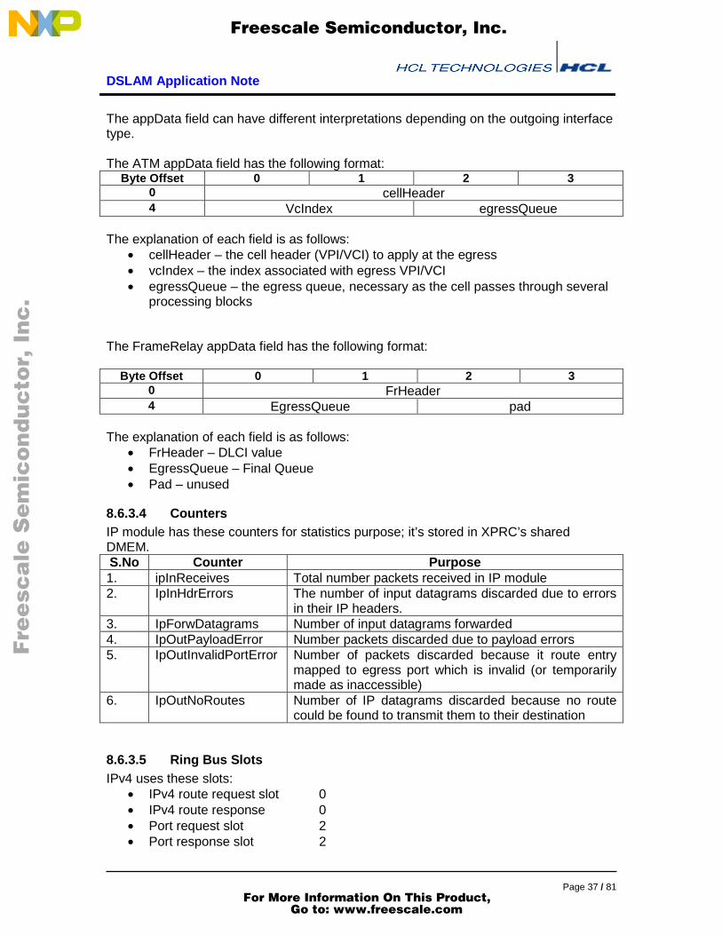
The appData field can have different interpretations depending on the outgoing interfacetype.
The ATM appData field has the following format:Byte Offset 0 1 2 3
0 cellHeader4 VcIndex egressQueue
The explanation of each field is as follows:• cellHeader – the cell header (VPI/VCI) to apply at the egress• vcIndex – the index associated with egress VPI/VCI• egressQueue – the egress queue, necessary as the cell passes through several
processing blocks
The FrameRelay appData field has the following format:
Byte Offset 0 1 2 30 FrHeader4 EgressQueue pad
The explanation of each field is as follows:• FrHeader – DLCI value• EgressQueue – Final Queue• Pad – unused
8.6.3.4 CountersIP module has these counters for statistics purpose; it’s stored in XPRC’s sharedDMEM.S.No Counter Purpose1. ipInReceives Total number packets received in IP module2. IpInHdrErrors The number of input datagrams discarded due to errors
in their IP headers.3. IpForwDatagrams Number of input datagrams forwarded4. IpOutPayloadError Number packets discarded due to payload errors5. IpOutInvalidPortError Number of packets discarded because it route entry
mapped to egress port which is invalid (or temporarilymade as inaccessible)
6. IpOutNoRoutes Number of IP datagrams discarded because no routecould be found to transmit them to their destination
8.6.3.5 Ring Bus SlotsIPv4 uses these slots:
• IPv4 route request slot 0• IPv4 route response 0• Port request slot 2• Port response slot 2
F
ree
sca
le S
em
ico
nd
uc
tor,
I
Freescale Semiconductor, Inc.
For More Information On This Product, Go to: www.freescale.com
nc
...

DSLAM Application Note
Page 38 / 81
8.7 Segmentation (CP8 & CP10)CP8 and CP10 implement AAL5 segmentation module. This CP gets messagedescriptors with bufType set to IPv4.
8.7.1 SDPThe SDP is configured for byte level re-circulation. It streams the IP packet andaccumulates CRC. For AAL5 cells, it adds the necessary pad bytes to make the SDUlength a multiple of 48 and creates the trailer. It then delivers fixed size chunks of theSDU to the CPRC. On the first chunk for an SDU, the SDP launches a port table lookup,whose results are used by the CPRC to determine the destination queue. The SDP doesnot interleave segmentations – it completely segments one SDU and delivers it to theCPRC before proceeding to the next SDU. The SDP accumulates payload CRC for all IPpackets.
8.7.1.1 TxByteThe TxByte processor performs the following operations on every packet:
• Reads the segType, pduSize and UUI from the merge space. Sends them toRxByte processor
• Read all the merge space fields following it. Send them to RxByte processor.• Initialize a counter with the negative of payload size.• Start sending the payload bytes, incrementing the counter for each byte sent out.
Accumulate CRC for each transmitted byte. Stop when the counter hits 0xff.• Initialize a counter with the number of pad bytes.• Start transmitting zeroes, incrementing this counter for every zero byte
transmitted. Accumulate the CRC on each zero byte. Stop when the counter hits0xff.
• The trailer should be sent for AAL-5 SDU. Send the UUI, CPI and payload length,accumulating the CRC on all of them. Now send the four bytes of the CRC. Thiscompletes the AAL5 trailer.
• Release the transmit scope and wait for data available from the RC.
TxByte gets the payload information from merge space as defined in section MergeSpace. TxByte is not configurable through control space.
8.7.1.2 RxByteThe RxByte processor performs the following sequence of operations:
• Receive the segType, pduSize and uui from the TxByte and copy them to theextract space.
• Clear the lastCell flag.• Receive the atmEgressQueue and destQueue from the TxByte and write them to
the extract space.• Receive the egress port from the TxByte and launch a port table lookup.• Initialize a counter Counter1 with the negative of pduSize(0xc1).• Stream out payload bytes to the Rx stage area. Increment Counter1 for every
byte transmitted. When Counter1 hits 0xff, hand the current scope over to theCPRC. If the data-9 bit is seen at any time in the payload, go to the next step.Wait for the next scope to become available and go back to the previous step.
F
ree
sca
le S
em
ico
nd
uc
tor,
I
Freescale Semiconductor, Inc.
For More Information On This Product, Go to: www.freescale.com
nc
...

DSLAM Application Note
Page 39 / 81
• At the end of the payload, data the TxByte sets the Data-9 bit. When this bit isseen, set the last cell flag to true. Copy the current value of Counter1 to thenumBytesLastPdu field and hand the current scope over to the CPRC.
• The packet segmentation is complete at this point, wait for more data to beavailable from TxByte
The RxByte processor writes information about incoming cells into extract space for theRC to use in its processing. The data structure is described in section Extract Space.RxByte is not configurable through control space
8.7.2 RCThe segmentation RC component uses two threads to perform its task, namely, an inputthread and an output thread. The initialization code starts the two threads. Each of theseis described next.
8.7.2.1 InitializationThe initialization phase in the segmentation CP does the following:
• Initializes buffer pools.• Creates contexts for the input and output threads• Initializes ring bus Tx message registers used by RxByte for launching port
lookup.• Setup DMA engines and initializes the SDP scopes.• Enables the SDPs
8.7.2.2 Input ThreadThe input thread handles incoming datagrams. Specifically, it does the following:
• De-queue message descriptors from the input queue• Reads the length of the IP packet to be segmented.• Determines the pad size• Calculate the number of cells that would be generated for this SDU.• Calculates the necessary pad bytes that should be added at the end of the
packet to make its size a multiple of 48 bytes• Allocates a Tx scope• Writes the IP packet buffer handle, egress port and egress queue from the IP
packet descriptor and the pad length to the merge space. Free the Tx scope,thus starting the SDP processing on this packet.
8.7.2.3 Output ThreadThe output thread handles outgoing datagrams. This logical function gets ATM cells fromthe SDP and en-queues them to the appropriate destination queue. Specifically, itcarries out the following sequence of operations:
• Allocate an Rx scope and read the extract space.• Check the Rx scope to see if the ‘new_sdu’ flag is set. If set, the SDP would have
launched a port table lookup. Read the egress queue from the extract space.• Wait for the port table lookup result.
F
ree
sca
le S
em
ico
nd
uc
tor,
I
Freescale Semiconductor, Inc.
For More Information On This Product, Go to: www.freescale.com
nc
...

DSLAM Application Note
Page 40 / 81
o If QoS is enabled for the port, the destination queue is the QoS queuefrom the port table lookup.
o If QoS is not enabled the destination queue is same as the egress queuefrom the table lookup.
• Create a message descriptor with bufType set to BT_ATM. Set the buffer handleto that of the cell delivered by the SDP and en-queue it to the destination queue.
8.7.3 Data Structures
8.7.3.1 Merge spaceThe RC writes information about outgoing packets to merge space for TxByte to use inits processing. The data structure has the following format:
Byte Offset 0 1 2 30 SegType PduSize Uui Cpi4 PayloadLength PadLength pad8 CellHeader12 EgressPort pad1 AtmEgressQueue16 DestQueue Pad
typedef struct {int8u segType;int8u pduSize;int8u uui;int8u cpi;int16u payloadLength;int8u padLength;int8u pad;CellHeader cellHdr;int8u egressPort;int8u pad1;int16u atmEgressQueue;int16u destQueue;
} SegMergeSpace;
• segType – indicates whether the packet is to be segmented for AAL5(SEG_AAL5)
• pduSize – specifies the size of chunks into which the packet is to be segmented(always 48 for AAL5)
• uui – specifies the user-to-user information• cpi – reserved, set to zero• payloadLength – size of the IP packet• padLength – number of zero bytes that need to be added to the payload• pad – Reserved• cellHdr – specifies the egress cell header to be used for AAL5• egressPort – the destination port number
F
ree
sca
le S
em
ico
nd
uc
tor,
I
Freescale Semiconductor, Inc.
For More Information On This Product, Go to: www.freescale.com
nc
...
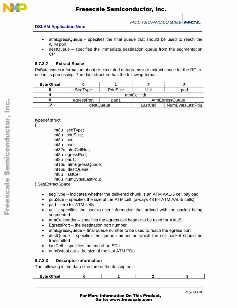
DSLAM Application Note
Page 41 / 81
• atmEgressQueue – specifies the final queue that should be used to reach theATM port
• destQueue – specifies the immediate destination queue from the segmentationCP
8.7.3.2 Extract SpaceRxByte writes information about re-circulated datagrams into extract space for the RC touse in its processing. The data structure has the following format:
Byte Offset 0 1 2 30 SegType PduSize Uui pad4 atmCellHdr8 egressPort pad1 AtmEgressQueue12 destQueue LastCell NumBytesLastPdu
typedef struct{
int8u segType;int8u pduSize;int8u uui;int8u pad;int32u atmCellHdr;int8u egressPort;int8u pad1;int16u atmEgressQueue;int16u destQueue;int8u lastCell;int8u numBytesLastPdu;
} SegExtractSpace;
• segType – indicates whether the delivered chunk is an ATM AAL-5 cell payload• pduSize – specifies the size of the ATM cell (always 48 for ATM AAL-5 cells)• pad –zero for ATM cells• uui – specifies the user-to-user information that arrived with the packet being
segmented• atmCellheader – specifies the egress cell header to be used for AAL-5.• EgressPort – the destination port number.• atmEgressQueue – final queue number to be used to reach the egress port• destQueue – specifies the queue number on which the cell packet should be
transmitted• lastCell – specifies the end of an SDU• numBytesLast – the size of the last ATM PDU
8.7.3.3 Descriptor informationThe following is the data structure of the descriptor:
Byte Offset 0 1 2 3
F
ree
sca
le S
em
ico
nd
uc
tor,
I
Freescale Semiconductor, Inc.
For More Information On This Product, Go to: www.freescale.com
nc
...

DSLAM Application Note
Page 42 / 81
0 bufHandle4 Length port_bufType8 appData
typedef struct {BsBufHandle bufHandle;int16u length;int16u port_bufType; /* 12:5 - port, 4:0 - bufType */union {
int8u byte[8];int16u hword[4];int32u word[2];AtmDescData atm;FrDescData frameRe;SegDescData seg;} appData;
} DescriptorMsg;
• bufHandle – reassembly buffer handle• length – chunk length• port_bufType – input port and buffer type of the next module• appData - Application specific data.
The AppData in the segmentation CP is of following format:
typedef struct SegDescData_s {CellHeader cellHeader;int8u flags_cpsPduLen; /* 7:6 flags; 5:0 cpsPduLen */int8u pad;int16u egressQueue;
} SegDescData;
Byte Offset 0 1 2 30 CellHeader4 Flags_cpsPduLen pad egressQueue
8.7.3.4 Ring Bus SlotsThe segmentation CP launches a lookup into Port Table. It uses following slots:
• Request Slot: 0• Response Slot: 0
8.8 Reassembly (CP9 & CP11)AAL5 re-assembly module is implemented in CP9 and CP11. An incoming messagedescriptor can have different bufType field value distinguishing between various packettypes. DSLAM application supports reassembly for AAL5. Hence, bufType field set toBT_ATM is an ATM cell descriptor and needs to be processed for AAL5 reassembly.
F
ree
sca
le S
em
ico
nd
uc
tor,
I
Freescale Semiconductor, Inc.
For More Information On This Product, Go to: www.freescale.com
nc
...

DSLAM Application Note
Page 43 / 81
8.8.1 SDPThe SDP for reassembly is configured for byte level loop back. It performs CRCaccumulation on the payload and initiates the DMA transaction to append the current cellpacket at the end of the SDU. On the non-last cell packet, the SDP initiates a CRC tableupdate using the XOR command in the non-last mode. The TLU CRC table is indexedby vcIndex. On the last cell for a SDU, the XOR command is used CRC Rx last mode toverify the accumulated CRC. The results come back on the ring bus and are examinedby the CPRC. Specifically, functions performed by each of the components of the SDPare described below:
8.8.1.1 TxByteThe TxByte processor performs the following functions:
• Wait for Tx scope from the CPRC• Initialize the CRC accumulator.• Forward the rasType, eom_offset, vcCidIndex, numalignedBytes and
numUnalignedByteCount to RxByte.The rasType is used by Rx CPRC to identifythe different packet types (AAL5 or others). The VcCidIndex holds vcIndex valuefor AAL5. The eom field holds the eom flag indicating whether this is the last cellof the packet. NumUnalignedBytes will always be zero for AAL5.
• Initialize a counter Counter1 (with 0xc1) to the value of numAlignedBytes. ForAAL5, this parameter is always 48. Initialize another counter Counter2 (withvalue 0xc2) numBytesPartialPayload.
• Start sending partial payload bytes from merge space, incrementing theCounter2 for every byte. When this counter hits 0xff, all unaligned bytes wouldhave been sent. Accumulate the partial CRC every byte transmitted.
• Now start sending the payload bytes, incrementing Counter1 for every byte andaccumulate the CRC. Stop accumulating CRC when the counter hits 0xff.
• Send the remaining payload bytes. These are the unaligned bytes and will berecirculated for the next packet. Hence, CRC should not be computed on thesebytes.
• After sending all payload bytes, the partial CRC accumulated thus far is sent.• At this point TxByte is done with processing the cell. It gives up the scope to the
CPRC and waits for the next cell/packet.
The RC writes information about cells to be reassembled into merge space for TxByte touse in its processing. The data structure is described in section Merge Space. TheTxByte processor is not configurable through control space.
8.8.1.2 RxByteThe RxByte processor performs the following functions:
• Wait for extract scope from CPRC.• Stream the rasType, eom, vcCidIndex, pduLength and numUnalignedByteCount
to the extract space. PduLength is the aligned byte count received from theTxByte.
• Make the scope available for CPRC, by setting L1_DONE flag.
F
ree
sca
le S
em
ico
nd
uc
tor,
I
Freescale Semiconductor, Inc.
For More Information On This Product, Go to: www.freescale.com
nc
...

DSLAM Application Note
Page 44 / 81
• Start streaming payload into the Rx staging area. The CPRC will setup the DMAto transfer it into SDRAM to the correct offset. Use a counter to determine whenthe payload ends.
• Copy the last six bytes of the payload into the extract space structures for uui,cpi, length and CRC. In case this is the last cell, the CPRC will need thisinformation for forwarding this packet to the IP CPRC. This information shouldalso go to the staging area.
• After the payload ends, the next six bytes are the accumulated CRC. Initiate aTLU XOR command using this CRC.
• Mark the scope status flags as L2_DONE, thus giving the trailer to the CPRC.• Wait for another scope to be available from the CPRC.
RxByte writes information about PDUs being reassembled into extract space for the RCto use in its processing. The data structure is described in section Extract Space. TheRxByte processor is not configurable through control space.
8.8.2 RCThe reassembly RC component uses two threads to perform its task, namely, an inputthread and an output thread. The initialization code starts the two threads. Each of theseis described next.
8.8.2.1 InitializationThe initialization phase in the segmentation CP does the following:
• Initializes buffer pools.• Creates contexts for the input and output threads• Initializes ring bus Tx message registers used by RxByte for RAS CRC Table.• Setup DMA engines and initializes the SDP scopes.• Enables the SDPs
8.8.2.2 Input ThreadThe input thread handles incoming datagrams. Specifically, it does the following:
• De-queues input ATM cell descriptors• Checks the buffer type of the incoming AAL-5 SDU. For the bufType field set to
BT_ATM the packet is an AAL-5 PDU. It fills the merge space with informationrequired by RxByte to reassemble the ATM cells at output thread.
• Starts the DMA of the packet and releases the scope for merge space.
8.8.2.3 Output ThreadThe output thread handles the outgoing reassembled AAL-5 SDUs. Specifically, itperforms following activities:
• Maintains a rasList structure to track re-assembly state per VC. An array of 1024RasList structures is maintained in DMEM. This array is indexed by the vcIndexfrom the ATM VC table for the input cell’s VPI and VCI. The vcIndex for AAL5VCCs is hence restricted to the range [0, 1023]. Each element of this array isinitialized with a valid buffer handle and offset set to zero.
F
ree
sca
le S
em
ico
nd
uc
tor,
I
Freescale Semiconductor, Inc.
For More Information On This Product, Go to: www.freescale.com
nc
...

DSLAM Application Note
Page 45 / 81
• After it receives a cell for AAL-5 reassembly, it locates its state entry in therasList array, using the cell’s vcIndex. The buffer handle in this specifies theSDRAM buffer at the end of which this cell needs to be appended. The offsetspecifies the length of AAL-5 SDU reassembled so far. This new cell needs to bewritten at the ‘offset’ location within the SDRAM buffer.
• Reads the extract space and updates the offset in the corresponding rasListarray entry.
• If the EOM Flag is set in the extract space, the current SDU has completed.When this flag is set, the output thread performs the following operations:
o Reads the rasType.o Wait for CRC results from TLU: - The SDP accumulates CRC for each SDU
in a TLU table, using the XOR command in CRC mode. On the last cell, theSDP issues the XOR command with CRC Rx last option. Upon getting thiscommand, the TLU first accumulates the CRC in the command and thenchecks to see if the accumulated CRC indicates CRC success. It returns aring bus success response on CRC success and a ring bus error otherwise.
o If the response is a success, an IP message descriptor is created for theSDU. It then waits for the SDP to deliver the aal5 trailer. The trailer containsSDU length, the aal5 UUI and the CRC. It fills the length field in the IPmessage descriptor using the length field from the trailer and dispatches themessage descriptor to the IP CPRC. It then sets the offset field in the rasListentry to zero and allocates a new buffer for the next SDU on this VCC.
o If the response indicates a CRC failure, it means that the AAL5 SDU sufferederrors in transit and should be discarded. The offset is set to zero so that thenext SDU on this VC can reuse the current SDRAM buffer.
o The descriptor in case of valid SDUs is then queued to the appropriatequeue. For all AAL5 SDUs, it queues it to IPv4 module.
o The maximum permitted SDU size is restricted to 2048 bytes in DSLAMapplication. If the offset field in the rasList entry exceeds 2048, the SDU is tobe discarded. For an SDU that exceeds 2048 bytes, subsequent ATM cellsare appended in the last 48 bytes of its buffer – when the output thread findsthe offset to exceed 2048, it always copies the current cell into the last 48bytes. When the last cell for this SDU arrives, the cell is copied into the last48 bytes and the offset is then set to zero. This effectively discards the SDUand makes the buffer available for the next SDU.
o Frees the scope to RxSDP
8.8.3 Data Structures
8.8.3.1 Merge spaceThe RC writes information about outgoing packets to merge space for TxByte to use inits processing. The data structure has the following format:
F
ree
sca
le S
em
ico
nd
uc
tor,
I
Freescale Semiconductor, Inc.
For More Information On This Product, Go to: www.freescale.com
nc
...

DSLAM Application Note
Page 46 / 81
Byte Offset 0 1 2 30 rasType Eom_offset vcCidIndex4 NumAlignedBytes NumUnalignedBytes NumBytes
PartialPayloadpduLen
8 PartialPayload12 PartialPayload16 PartialPayload20 PartialPayload
typedef struct{int8u rasType;int8u eom_offset;int16u vcCidIndex;int8u numAlignedBytes;int8u numUnAlignedBytes;int8u numBytesPartialPayload;int8u pduLen;int8u partialPayload[16]; /* Partial Payload */
} RasMergeSpace;;
• rasType – 0x01 for AAL5• eom – 0x00 ,if this is not the last cell and 0x80 ,if it is the last cell of a SDU• vcCidIndex – the VC Index• numAligned – the number of bytes in the data stream that should be transferred
to SDRAM• numUnAligned – the number of bytes in the data stream that will be transferred
to the extract space• numBytesPartial – the number of unaligned bytes from the previous ATM cells• pduLen – the size of the ATM PDU• partialPayload[16] – the unaligned bytes from previous ATM PDU
8.8.3.2 Extract SpaceRxByte writes information about recirculated datagrams into extract space for the RC touse in its processing. The data structure has the following format:
Byte Offset 0 1 2 30 rasType Eom_offset vcCidIndex4 PduLength NumUnalignedBytes pad8 Uui Cpi PayloadLength12 CRC16 PartialPayload20 PartialPayload24 PartialPayload28 PartialPayload pad
typedef struct {int8u rasType;
F
ree
sca
le S
em
ico
nd
uc
tor,
I
Freescale Semiconductor, Inc.
For More Information On This Product, Go to: www.freescale.com
nc
...

DSLAM Application Note
Page 47 / 81
int8u eom_offset;int16u vcCidIndex;int8u pduLength;int8u numUnAlignedBytes;int8u reserved[2];int8u uui;int8u cpi;int16u payloadLength;int32u crc;int8u partialPayload[15];
} RasExtractSpace;
• rasType – 0x00 for AAL5.• eom – 0x00 if this is not the last cell and 0x80 if it is the last cell of a SDU• vcCidIndex – VC index• pduLength – the size of the ATM PDU• numUnAligned – the number of unaligned bytes in the extract space• pad – unused• uui – user-to-user indication from the AAL5 trailer• cpi – reserved• payloadLength – size of the reassembled AAL5• crc – CRC-32 from the AAL5 trailer• partialPayload[15] – the unaligned bytes from current ATM PDU
8.8.3.3 RasListThe RasList structure is used to track re-assembly state per VC. It is an array of 1024structures with the following format:
Byte Offset 0 1 2 30 BufHandle4 Offset
• bufHandle – the handle of the buffer in which cells are being reassembled• Offset – the offset in the reassembly buffer at which the next cell should be
placed
8.8.3.4 Descriptor informationThe following is the data structure of the descriptor, which is en-queued or de-queued:
Byte Offset 0 1 2 30 bufHandle4 Length port_bufType8 appData12 appData
F
ree
sca
le S
em
ico
nd
uc
tor,
I
Freescale Semiconductor, Inc.
For More Information On This Product, Go to: www.freescale.com
nc
...
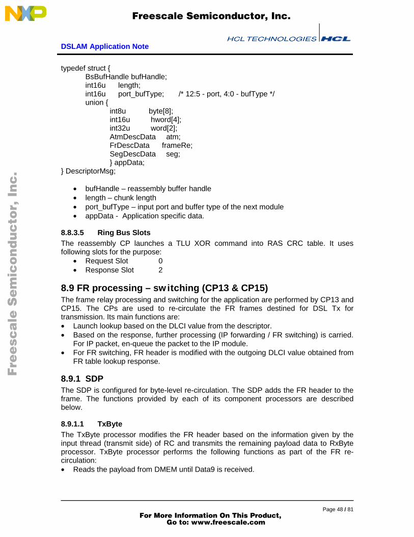
DSLAM Application Note
Page 48 / 81
typedef struct {BsBufHandle bufHandle;int16u length;int16u port_bufType; /* 12:5 - port, 4:0 - bufType */union {
int8u byte[8];int16u hword[4];int32u word[2];AtmDescData atm;FrDescData frameRe;SegDescData seg;} appData;
} DescriptorMsg;
• bufHandle – reassembly buffer handle• length – chunk length• port_bufType – input port and buffer type of the next module• appData - Application specific data.
8.8.3.5 Ring Bus SlotsThe reassembly CP launches a TLU XOR command into RAS CRC table. It usesfollowing slots for the purpose:
• Request Slot 0• Response Slot 2
8.9 FR processing – switching (CP13 & CP15)The frame relay processing and switching for the application are performed by CP13 andCP15. The CPs are used to re-circulate the FR frames destined for DSL Tx fortransmission. Its main functions are:• Launch lookup based on the DLCI value from the descriptor.• Based on the response, further processing (IP forwarding / FR switching) is carried.
For IP packet, en-queue the packet to the IP module.• For FR switching, FR header is modified with the outgoing DLCI value obtained from
FR table lookup response.
8.9.1 SDPThe SDP is configured for byte-level re-circulation. The SDP adds the FR header to theframe. The functions provided by each of its component processors are describedbelow.
8.9.1.1 TxByteThe TxByte processor modifies the FR header based on the information given by theinput thread (transmit side) of RC and transmits the remaining payload data to RxByteprocessor. TxByte processor performs the following functions as part of the FR re-circulation:• Reads the payload from DMEM until Data9 is received.
F
ree
sca
le S
em
ico
nd
uc
tor,
I
Freescale Semiconductor, Inc.
For More Information On This Product, Go to: www.freescale.com
nc
...

DSLAM Application Note
Page 49 / 81
• Transmit the egress_queue, port_buftype and length of the packet for output threadprocessing.
• Reads the outgoing DLCI value from the merge space and modify the existing valuein the packet with the new value.
• Set the congestion control information fields in the FR header to zero.• Sends the FR payload data to RxByte• Switches scope and waits for next packet to be available.
8.9.1.2 RxByteThe RxByte processor fills the extract space based on the descriptor information sent bythe TxByte processor and streams the modified payload to the output thread (receiveside) of the RC .The RxByte processor performs the following functions as part of the FRrecirculation:
• Waits for a receive scope to be available.• Receives the bytes from the TxByte processor• The first two bytes of the payload contain the egress_queue. This is written to
the extract space. The next two bytes contain the outgoing port informationand buffer type information. This will also be written to the extract space.
• The packet length is indicated in the next two bytes. This is written to theextract space and header ready is indicated in the rxStatus register.
• Stream the remaining payload to DMEM.• When data9 (i.e., ninth bit is set in the incoming payload) is received switches
scope.
8.9.2 RCThe RC manages the FR re-circulation. All CPs that want to transmit FR frames, en-queue their packets to the FR re-circulation CP so that the FR header is modified in theframe before transmission.
8.9.2.1 InitializationThe initialization component initializes the data structures and registers used by the RC.The following activities are done during the initialization:
• Initializes the buffer pools.• Creates input and output threads.• Initializes the FR table lookup slots.
8.9.2.2 Input ThreadThe Input thread services all the FR traffic which needs the FR header modification inthe frame is queued here. This passes the frame to SDP.
• De-queues the descriptor information.• Launch a lookup based on the DLCI value from the descriptor. If the lookup fails,
silently drop the packet.• While waiting for the response, process the next packet from the queue.
F
ree
sca
le S
em
ico
nd
uc
tor,
I
Freescale Semiconductor, Inc.
For More Information On This Product, Go to: www.freescale.com
nc
...

DSLAM Application Note
Page 50 / 81
• Based on the FR table lookup response, the next level processing is identified.(IPforwarding or FR switching).
• For IP packet, build the descriptor with the appropriate fields and enqueue it to IPmodule.
• For the packet to be FR switched, fill the merge space with outgoing DLCI value(from the lookup response), egress_queue, port_buftype and the length of thepacket.
• Initiates payload transfer from SDRAM to DMEM and switches context to the nextthread
• Loops to the beginning to wait for another descriptor
8.9.2.3 Output ThreadThe output thread handles the incoming packets from the RxByte processor.• Waits for the header processing completion on the RxByte processor indicated by
L1Done in the rxStatus register.• Allocates new buffer and initiates the payload transfer from DMEM to the SDRAM.• Creates the descriptor with buffer handle, buffer length and port_bufType information• Enqueue the descriptor to the appropriate destination based on the egress_queue.• Switches context to the next thread.• Loops to the beginning to wait for another scope to be available
8.9.3 Data StructuresThe merge space and Extract space structures used in the FR processing are explainedbelow:
8.9.3.1 Merge spaceThe RC writes information needed for FR encapsulation and descriptor fields to be usedby Rx CPRC, into merge space. TxByte processor does FR encapsulation and sendsthe descriptor fields to RxByte. The data structure has the following format:
Byte Offset 0 1 2 3
0 FrHeader4 Port_bufType Length8 EgressQueue Pad
The explanations for the above-mentioned fields will be as follows• FrHeader -The outgoing DLCI value.• EgressQueue - specifies the final queue.• port_buftype – Outgoing interface information and the buffer type• Length – Length of the packet• Pad - unused
8.9.3.2 Extract SpaceRxByte processor writes descriptor information into extract space for the RC to use in itsprocessing. The data structure has the following format:
F
ree
sca
le S
em
ico
nd
uc
tor,
I
Freescale Semiconductor, Inc.
For More Information On This Product, Go to: www.freescale.com
nc
...

DSLAM Application Note
Page 51 / 81
Byte Offset 0 1 2 30 EgressQueue Pad4 Port_buftype Length
The explanations for the above-mentioned fields will be as follows• EgressQueue - specifies the final queue.• port_buftype - Outgoing interface information and the buffer type• Length - Length of the packet.• Pad - unused.
8.9.3.3 Descriptor information for FRThe Rx modules will fill the FR descriptor information to be used by the FR re-circulationmodule for processing. The format of the descriptor will be as follows:
Byte Offset 0 1 2 30 BufHandle4 Length PortBufType8 FrHeader
The explanations for the above-mentioned fields will be as follows• BufHandle - Handle of the buffer being re-circulated• Length - specifies the length of the buffer.• Port_bufType - a bitmask is defined as follows:
o b12-5: port – the output port on which this datagram to be transmitted.o b4-0: bufType – the type of buffer being re-circulated and the egress port type
(could be BT_IPV4, BT_FR)• FrHeader: specifies the DLCI value and the congestion control Information.
8.9.3.4 Ring Bus SlotsFR uses these slots
• FR Request slot 1• FR Response slots 2,3
8.9.4 Issues/Enhancements
• At present the congestion control information in the FR header is not processed.• The two bytes address format of DLCI (10-bit) is supported now.• FR module can be Extended to support three (16-bit DLCI) and four bytes (23-bit
DLCI) address format of DLCI.
8.10 Fabric PortThe fabric port implements the Utopia Level 2 interface. This port handles only ATMcells. Cells received on the interface are typically forwarded to other ATM processing
F
ree
sca
le S
em
ico
nd
uc
tor,
I
Freescale Semiconductor, Inc.
For More Information On This Product, Go to: www.freescale.com
nc
...

DSLAM Application Note
Page 52 / 81
blocks based on VPI/VCI lookup. The Fabric Port sends cells received from other ATMprocessing blocks to the UL-2 interface.
8.10.1 FpTxThe FpTx component de-queues descriptors and sends utopia cells to the UL-2 adapter.The micro-code uses information in the descriptor to construct the ATM header thentransmit it. The Hardware then transmits the buffer contents specified by the bufferhandle in the descriptor. Specifically, FpTx does the following:
• Sends the 4-byte ATM header provided by the descriptor• Asserts the EOM bit in the PTI byte, if necessary• Sends the 48-bytes of payload• Switches to the next scope
FpTx microcode may also assist with segmentation. FpTx assumes that the PDU lengthis a multiple of 48 bytes, which will be the case for any PDU sent by the segmentationcluster. If the PTI field indicates EOM, then FpTx will segment the PDU and mark thePTI EOM bit appropriately in the last cell. Otherwise, FpTx sends the cell with the PTIindicating no EOM. FpTx receives information through merge space about the PDU tobe sent.
8.10.2 FpRxThe FpRx component receives ATM-like cells from the UL-2 adapter, validates them,and forwards descriptors to the next ATM processing block. Every cell is considered anindependent PDU and marked as FOM. The HW splits the cell into header (8 bytes) andpayload (48 bytes). The lower four bytes of the header overlap are the same as the firstfour bytes of the payload. The micro-code parses the ATM header and launches alookup of the VPI/VCI. If the lookup fails, the cell is dropped by the Fabric Port hardware.Otherwise, the ATM header, the STF header and lookup response data are copied intothe descriptor, the HW moves the payload into a buffer, and the descriptor is placed inthe queue specified by the lookup response. In particular, FpRx does the following:
• Writes the ATM header to extract space• Writes the VPI/VCI into the TLU Tx message slot• Sets the flow ID to a constant (0)• Sets the segment type to first and only message (FOM)• Sets the PDU size to a constant (52)• Launches the VPI/VCI lookup• Switches to the next scope
Because the FpRx is not able to preserve much state information, it is incapable ofdetermining when the first cell of an AAL-5 PDU is received. For this reason, the FP isnot able to perform the reassembly operation and so each cell is treated independently.FpRx uses extract space to store information about the incoming segment.
8.10.3 DBEThe descriptor build engine (DBE) component uses the data put into extract space bythe FpRx and the results of the TLU to build a descriptor that will be queued to the next
F
ree
sca
le S
em
ico
nd
uc
tor,
I
Freescale Semiconductor, Inc.
For More Information On This Product, Go to: www.freescale.com
nc
...

DSLAM Application Note
Page 53 / 81
block for further processing. The DBE microcode fills in the descriptor data structurewhen the TLU signals that the lookup has completed. If the lookup fails the DBE will dropthe incoming cell.
8.10.4 Data Structures
8.10.4.1 Merge spaceThe FpTx hardware copies the descriptor data from the payload bus to merge spaceafter a de-queue operation. The data structure has the following format:
Byte Offset 0 1 2 30 bufHandle4 Length port_bufType8 CellHeader12 Appdata
• bufHandle – the handle to the buffer containing cell payload• length – length of the payload in the buffer• port_bufType – unused by the FP• cellHeader – the cellHeader to be prepended to outgoing cells, PTI indicates
EOM if segmentation is desired• appData – unused by the FP
8.10.4.2 Extract Space
The FpRx hardware fills in extract space before passing control to the DBE. Extractspace has the following format:
Byte Offset 0 1 2 30 cellHeader
cellHeader – the cell header from the received cell
8.11 Table Lookup UnitThe table lookup unit provides lookup table management. The TLU stores its tableinformation in external SRAM that is managed by TLU’s SRAM controller. Theapplication creates multiple tables in the TLU for data path forwarding and state memorysupport. The tables are summarized below and described in detail in subsequentsections.
Table Name Table Type Table ID Key Size (b) Entry Size (B)Port Table Data 0 8 8
IPV4 Route Table LPM 2 32 16ATM VC Table HTK 4 32 16
Reassembly CRCTable
Data 6 11 4
FR DLCI Table HTK 11 21 16
F
ree
sca
le S
em
ico
nd
uc
tor,
I
Freescale Semiconductor, Inc.
For More Information On This Product, Go to: www.freescale.com
nc
...

DSLAM Application Note
Page 54 / 81
The table fields and lookup key construction are defined in the appropriate sectionswhere this lookup is launched.
8.11.1 Port TableWhen the ingress processor launches a lookup to make a forwarding decision, theresponse usually returns the port number and layer 2 addresses. In order to map theport to a queue and determine if processing other than simple forwarding is needed, theingress process must also launch a lookup in the port table. The port table is a data tablewith a 32-bit key, only 8 bits are significant. The key (or index) is equal to the portnumber.
Each entry of the table has the following format:
Byte Offset 0 1 2 30 PortType Flags egressQueue4 QosQueue pad
The description of each field is as follows:• portType – the type of egress port (ATM orFR)• flags – a bitmap as follows
o b7: Valid – flag indicating whether or not the port is valido b6: QoS – flag indicating whether QoS must be performed on this porto b4-0: reserved for future use
• egressQueue – the egress queue of the packet or cell• qosQueue – the queue of the QoS processor for this packet
8.11.2 IP V4 Routing TableThe IPv4 routing table is a longest prefix match table with a 32-bit key. The key is equalto the IP destination address.Each entry of the table has the following format:
Byte Offset 0 1 2 30 port pad Type MaskBits4 AppData8 AppData12 pad1
The description of each field is as follows:• port – the egress port number• type – the type of route entry (internal, local, gateway, etc.), unused• maskBits – the number of significant bytes in the key• appData – application specific data, usually contains L2 address, see below• Pad, pad1 – unused
The appData field can have different interpretations depending on the egress (outgoinginterface). For example, an ATM egress would have a VPI/VCI.
The ATM appData field has the following format:
F
ree
sca
le S
em
ico
nd
uc
tor,
I
Freescale Semiconductor, Inc.
For More Information On This Product, Go to: www.freescale.com
nc
...

DSLAM Application Note
Page 55 / 81
Byte Offset 0 1 2 30 EgressCellHeader4 EgressQueue pad
The description of each field is as follows:• EgressCellHeader – the cell header (VPI/VCI) to use at the egress• EgressQueue - TrafficQueue mapped to Q-3 for applying ATM TM• pad – unused
The FR appData field has the following format:
Byte Offset 0 1 2 30 egressFrHeader4 Pad
The description of each field is as follows:• egressFrHeader – the FR header to use at the egress.• Pad – unused
8.11.3 ATM VC TableEvery ATM cell that enters the application has its VPI/VCI looked up in the ATM VCtable to determine if the cell is on a valid VC and how to process it. The ATM VPI/VCItable is a HTK table with a 32-bit key. The key is constructed as follows:
47 44 43 36 35 20 19 8 7 00 VPI VCI 0 Port
Each entry of the table has the following format:
Byte Offset 0 1 2 30 Flags_egressPort VcIndex4 EgressCellHeader8 EgressQueue Port_bufType12 DestQueue OamPM pad
The description of each field is as follows:• egressCellHeader – the ATM cell header (not including HEC) to be applied to the cell
at the egress• vcIndex – the VC index used by AAL-5 SARs to index their state tables• flags_egressPort – a bitmap as follows:
o b15: AAL5 VC – flag indicating the VC is an AAL-5 type VCo b14-8: reserved for future useo b7-0: egressPort – the egress port from which the cell must exit
• egressQueue – the egress queue of the ATM cell, this is necessary for the FP whichcan launch only one lookup. This also represents the trafficQueue, to be used if QoSis enabled for this egress port
F
ree
sca
le S
em
ico
nd
uc
tor,
I
Freescale Semiconductor, Inc.
For More Information On This Product, Go to: www.freescale.com
nc
...

DSLAM Application Note
Page 56 / 81
• port_bufType – the egress port and buffer type packaged in a way the FP can use• destQueue – the queue of the next ATM processing block, this is necessary for the
FP which cannot act on TLU response data• oamPm – MSB indicates OAM processing required on this VC, remaining bits are
index into local OAM table• pad – unused
8.11.4 RAS CRC TableThe reassembly CRC table stores the partial CRC result calculated during reassembly.The key is the VC index retrieved from the ATM VC table. Each entry of the table hasthe following format:
Byte Offset 0 1 2 30 Pad CrcLength4 CrcPartial
The description of each field is as follows:• pad – unused• crcLength – number of cells whose CRC has been calculated so far• crcPartial – partial CRC value calculated so far
8.11.5 FR DLCI TableFR table is HTK table with 32-bit key. The key is formed by the concatenation of 10-bitDLCI value and 11-bit interface ID. Currently the two-byte address format is used to formDLCI (10-bit).
Bits: 20 10 Bits: 9 0Interface ID DLCI
The format of each entry in the FR tableByte Offset 0 1 2 30 frHeader4 flags_egressPort padThe explanations for the above-mentioned fields will be as follows:
• int32u FrHeader -specifies the DLCI value and the congestion control information.• int16u flags_egressPort – a bitmap is defined as follows
o b15-14 : flag – value set to 1 indicates the FR.o b13-8: reserved for future useo b7-0 :egress port –output port
F
ree
sca
le S
em
ico
nd
uc
tor,
I
Freescale Semiconductor, Inc.
For More Information On This Product, Go to: www.freescale.com
nc
...

DSLAM Application Note
Page 57 / 81
8.12 Buffer Management UnitThe Buffer Management Unit (BMU) manages the C-3e NP’s data buffers for payloadmanagement. The DSLAM application allocates one buffer pool per CP. The size of thebuffers in each buffer pool is 4096 bytes (the buffer sizes must be a power of 2). Theapplication configures 1024 buffers per CP.
There are several formats for the data in a BMU buffer, supported by DSLAMapplication. Various formats support communication between different applicationcomponents. The formats are specified by an enumeration that is typically included inthe buffer descriptor. The enumeration and a descriptor of each buffer type is listed:
Buffer Type Buffer DescriptionBT_UNKNOWN Contents of the buffer are unknownBT_IPv4 IPv4 datagramBT_ATM ATM cell payload; length will be 48BT_FR FrameRelay dataBT_LAST Place holder to define limit of buffer type enumeration
8.13 Queue Management UnitThe information provided in this section is the mapping of queues, which are used bydifferent Channel processors. The QMU is configured to use 32 byte descriptors. Thenumber of Queues allocated to each application block will be as follows:
Queue owner Number of queues Queue useDSL Tx 64 Cluster 0 Tx processing
which is connected to M-2Quad.
OC-3c Tx 64 Cluster 1 Tx processing,which is conentced to OC-3c interfaces.
IP 1 IP forwarding assistance forDSL channels and OC-3cinterfaces.
Segmentation 1 AAL-5 segmentation.Reassembly 1 AAL-5 reassembly.FR 1 FR Tx processing.XP 5 ATM control and host.FP (UL-2) 32 UL-2 egress.
Communications between the application-blocks running on different Channelprocessors is accomplished by the source CP en-queuing a descriptor to the queueassociated with the destination CP. All the QMU queues, including the inter modulecommunication queues are mapped to Q-3 VOPs. Channel processors use extendeden-queue mechanism for enqueuing packets to Q-3.
F
ree
sca
le S
em
ico
nd
uc
tor,
I
Freescale Semiconductor, Inc.
For More Information On This Product, Go to: www.freescale.com
nc
...

DSLAM Application Note
Page 58 / 81
8.14 Q-3 configurations for CPs, XP and FP
8.14.1 XP InitializationXP initialization component does the following:
• Initializes the system services. Queuing services will be initialized in externalmode using qsExtendedInitialize () with descriptor size 32 bytes.
• Waits for the host message for completion of Q-3 TMC configuration.• Configures the 128 VOPs (5 for XP, 32 for FP and remaining for CPs) using
qsQueueCreate () and qsQueueConfig () functions. The VOPs will denote theQMU queues for dequeing the descriptor by other C-3e components (XP, FP andCPs). For information about number of VOPs for each component see the queueassignment information in Section 8.13
• Performs other initializations as mentioned in Section 8.1.1.
8.14.2 Host ConfigurationsHost is responsible to perform the Q-3 TMC configurations as shown in figure 8. Itconfigures the following parameters in the Q-3 map.
• The total number of QMU queues assigned for CPs, XP and FP are 128 (Seequeue assignment in Section 8.13). One QMU queue will be mapped to one Q-3traffic queue. So total number of Q-3 traffic queues to be configured will be 128.
• One Level2 scheduler having one input leg will be configured for each trafficqueue. So it will need 128 level2 schedulers for normal forwarding path in Q-3.
• Since Q-3 is used to forward the descriptor from traffic queue all the way to C-3eQMU via Q-3 hierarchy, there will be no discard path to be configured.
• One level1 scheduler having 128 input legs will be required. Max number of inputlegs in level1 scheduler will be 1K.
• At the top level, it is mandatory to have one level0 scheduler in Q-3 hierarchy. Itwill be configured to have one input leg.
• Number of VOPs to be configured will depend on the number of QMU queues.So 128 VOPs will be configured.
The steps for host configuration starting from top to bottom in Q-3 hierarchy (i.e. fromlevel 0 scheduler to traffic queues) are described as follows.
• Initializes the Q-3 TMC using qsTmcInitialize ().• Creates one level0 RR scheduler with one input using qsTmcSchedCreate ().• Creates parent buffer pool and buffer pool associated with it using
qsTmcBufferPoolCreate (). These buffer pools will be used by traffic queues.• Creates one level1 RR scheduler with 128 inputs. This scheduler will feed the
level0 RR scheduler.• Creates the 128-level2 schedulers each having one input legs that will receive
the input descriptor from traffic queues configured for CPs, XP and FP. Theseschedulers will feed the level1 RR scheduler. The total number of level2schedulers to be supported is 18K.
• Creates 128 traffic queues that will pass the traffic to the Q-3 hierarchy. Totalnumber of traffic queues to be supported is 64K.
F
ree
sca
le S
em
ico
nd
uc
tor,
I
Freescale Semiconductor, Inc.
For More Information On This Product, Go to: www.freescale.com
nc
...

DSLAM Application Note
Page 59 / 81
• Creates the 128 VOPs using qsTmcVopCreate(). These VOPs are mapped to128 QMU queues of C-3e. CPs, XP and FP in C-3e will use these VOPs todequeue the traffic. The total number of VOPs to be supported is 512.
• Enables the Q-3 configuration map using qsTmcEnqueueEnable().• Communicates with XP to indicate that Q-3 configuration is done.
8.14.3 RCEach component’s RC will enqueue the descriptor to its configured Traffic queue usingqsEnqueueExt () and dequeue it from its configured VOP using qsDequeue ().
8.14.4 Assumptions• As per “Functionality comparison document between old Q-5 and projected Q-5
TMC FPGA”, new Q-5 can have up to 256 discard configurations. It is assumedthat discard configuration refers to discard block. So two discard blocks (tokenbucket discard blocks and RED discard block) will be configured for each of 8Ktraffic flows having one discard queue for IP QoS. Similarly, one token bucketdiscard block will be configured for all 8K traffic flows for ATM TM.
• 3 Levels of scheduler Level 0, Level 1 and Level 2, each supporting SP, RR andWFQ algorithms will be supported.
F
ree
sca
le S
em
ico
nd
uc
tor,
I
Freescale Semiconductor, Inc.
For More Information On This Product, Go to: www.freescale.com
nc
...

DSLAM Application Note
Page 60 / 81
QMU
128 Level2schedulers(One inputfor each)
128 differentVOPs(For CPs, XPand FP)
128 TQs(for CPs, XPand FP)
RR - - - - - - -
VOP
CPs, XP and FP
Level1scheduler(128 inputs)
VOP VOP VOP
NoDiscardBlock
RR RR RR
RR
- - - - - - -
RR
Level0scheduler(One input)
9 HOST PROCESSOR ARCHITECTURE
The DSLAM Line Card host component uses an object oriented (OO) design. It islayered on top of the host services layer and utilizes the provided host services API’swherever possible when interacting with the NP. Direct calls to NP driver functions maybe necessary for implementation of certain functions.
Figure 6 - Q-3 configuration map for CPs, XP and FP
F
ree
sca
le S
em
ico
nd
uc
tor,
I
Freescale Semiconductor, Inc.
For More Information On This Product, Go to: www.freescale.com
nc
...

DSLAM Application Note
Page 61 / 81
Wherever applicable, the host components use the OS abstraction layer (OSAL)services for timers, queues, tasks, threads, etc. to allow porting to other RTOS’s and tosupport native host simulation for development and regression testing.
The following activities performed at Host:
• Creation and Initialization of TLU tables• Creation of pipes needed for packet I/O• Initializes all peripheral hardware (C-Port Family M-2 Quad Adapter, C-Port Family
UL2 Interface Adapter) and sets a default configuration.• Initializes any required on-chip structures in appropriate DMEM.• Provides needed info to chip code via HCA (for example, tableID’s).• Spawns all necessary host tasks (receiver, statistics, Command Console)• Configuration and statistics gathering using TLU Tables• Configuration and statistics gathering of Link /channel (ATM/FR)• Configuration and statistics gathering of ports (DSL/ATM /FP)
10 HOST PACKET I/OProcesses running on the host can send and receive packets/cells via the NP using theprovided Host services. These services interact with code running on the NP thatperforms the actual packet/cell transfer between the host and the NP and in the case oftransmission perform the actual queuing of the packet to the appropriate output port.
10.1 ResourcesHost uses these resources to perform packet input/output.• Bi-directional DMA Pipe between host and NP• Dedicated host transmit BMU buffer pool
10.2 Packet ReceptionThis section describes packet flow from the ingress, through the NP, to the host.
10.2.1 Network ProcessorTraffic intended for the host is processed identically to traffic destined for forwarding toother NP ports except the QMU descriptor for the host packet is placed in a speciallydesignated "host RX" queue by the receiving CP. This could be either as the normalresult of a TLU lookup or as the result of the CP matching against a certain field withinthe packet.
XP services the "host RX" queue. When the XP detects the queue is non-empty, itdequeues the descriptor and from the data contained within it, it creates a structure thatit sends to the host to inform it of a received packet via the host services Pipemechanism. This structure contains the packet type, length, and BMU BufferHandle ofthe data.
F
ree
sca
le S
em
ico
nd
uc
tor,
I
Freescale Semiconductor, Inc.
For More Information On This Product, Go to: www.freescale.com
nc
...

DSLAM Application Note
Page 62 / 81
10.2.2 HostA dedicated receive task on the host checks the status of the DMA pipe and upon findingan entry, sets up a DMA operation on the NP to move the data from the NP’s BMUbuffer to a buffer residing in host memory. When the DMA operation completes, thereceive task upcalls based on the packet type. The host also initiates a BMU buffer freeoperation for the packet’s buffer on the NP using the doXpRequest mechanism(currently a direct call to the dcpMgr object).
10.3 Packet TransmissionThis section describes packet flow from the host, through the NP, and to the egress.
10.3.1 HostA process running on the host that wants to transmit a packet calls the sendPacket ()function with a buffer pointer, buffer length, port handle, and packet type. ThesendPacket function will initiate a DMA operation (controlled by the NP) to move thepacket from host memory to a BMU buffer allocated from the host’s dedicated transmitpool. When the DMA has completed, the host will place a structure describing the packet(currently the same one used on packet reception) in the DMA pipe to inform the NP thatthere is something to transmit. The host uses the doXpRequest mechanism to interruptthe XP to do the actual notification.
10.3.2 Network ProcessorBased on the host structure read from the DMA Pipe, the XP will construct a QMUdescriptor for the host packet and then queue it based on the port. The XP will alsoallocate a new buffer from the host’s pool and give it to the host via the response to thedoXpRequest transmit command for use by the host’s next transmit. XP returns the BMUbuffer from the current transmit to the host’s pool via the normal buffer freeing followingtransmission.
11 CONSOLE COMMAND SHELL COMMANDS
This section defines the commands that are available at the console.
11.1 Application ControlApplication uses this command at startup. Execute this command, after loading theapplication package.
• start – after a packload, initializes host and NP to default settings and releases theXP.
11.2 Table Maintenance and DisplayHost creates and initializes the tables used in DSLAM application. For each table in theapplication, it supports the following operations:
• getEntry Table {key} – gets the entry corresponding to the provided key• deleteEntry Table {key} – deletes the entry corresponding to the provided key
F
ree
sca
le S
em
ico
nd
uc
tor,
I
Freescale Semiconductor, Inc.
For More Information On This Product, Go to: www.freescale.com
nc
...

DSLAM Application Note
Page 63 / 81
• setEntry Table {key} {entry info} – adds/modfies the entry corresponding tothe provided key
• display Table – displays the entire table• flush Table – flushes the entire table
In each of the above commands, the italicized “Table” part of the command is replacedwith the name of the table. The following tables are supported:• Port table• Atm VC table• IPv4 Route table• FR DLCI table
Having a command set for each table type allows the “help” facility for each command toshow only the required key and entry parameters for that particular table type. Thealternate approach of having the table type as a parameter would require that allpossible key and entry types be displayed in the “help”.
11.3 DSL Link Configuration and Status
These commands allow the individual DSL links to be configured for ATM (default) or FR• configDslLink {dslLinkIndex} [ATM|FR] - configures a DSL link• removeDslLink {dslLinkIndex} – removes the DSL link• showDslLink {dslLinkIndex} – displays the DSL link configuration
11.4 OC-3c interface Configuration and StatusThese commands allow for the configuration and monitoring of the OC-3c interfaces.
• configOc3If {oc3PortIndex} [ATM|FR] - configures an OC-3c interface.• removeOc3If {oc3PortIndex} – removes an OC-3c interface.• showOc3If {oc3PortIndex} – displays an OC-3c interface configuration.
11.5 ATM Configuration and StatusThese commands allow for the configuration and monitoring of ATM parameters on anOC-3c interface.• configAtm {oc3PortIndex} {atmParam} {atmParamValue}– configures the ATM
interface with one of the following parameters :o Payload Scrambling On/Off
• showAtm {oc3PortIndex}– displays the ATM configuration on the specified OC-3c interface.
F
ree
sca
le S
em
ico
nd
uc
tor,
I
Freescale Semiconductor, Inc.
For More Information On This Product, Go to: www.freescale.com
nc
...

DSLAM Application Note
Page 64 / 81
11.6 FR Configuration and Status
These commands allow for the configuration and monitoring of FR parameters on DSLlinks and OC-3c interfaces.• configFr {DSL|OC3} {portIndex} {FrParameter} (FrParameterValue} –
configures FR with one of the following parameters:o mru
• showFr {DSL|OC3} {portIndex} – displays the FR configuration on the specifiedDSL link or OC-3c interface.
The default FR configuration is:• mru size = 4096
11.7 Statistics
These commands displays statistics gathered from various ports.
11.7.1 ATM statisticsThe following command displays the ATM statistics gathered from the DSL or OC-3cinterface..• getDslAtmStats {dslPortIndex} – displays the statistics for the specified DSL
port configured for ATM.• getOc3AtmStats {oc3PortIndex} – displays the statistics for the specified ATM
OC-3c port
11.7.2 FR statisticsThe following command displays the FR statistics gathered from the DSL or OC-3cinterface.
• getDslFrStats {dslPortIndex} – displays the statistics for the specified DSLinterface configured for FR .
• getOc3FrStats {oc3PortIndex} – displays the statistics for the specified OC-3cinterface configured for FR .
12 HOST PROCESSOR TO NETWORK PROCESSORINTERFACE
This section details the control structures residing in the various NP DMEM’s that thehost component must initialize and maintain. These structures are exported in the NPsource code so that the host can acquire the DMEM address from the package file.
F
ree
sca
le S
em
ico
nd
uc
tor,
I
Freescale Semiconductor, Inc.
For More Information On This Product, Go to: www.freescale.com
nc
...

DSLAM Application Note
Page 65 / 81
12.1 FRThe following data structures relate to the FR components running on both the host andnetwork processors.
12.1.1 FR Link ParametersThis structure holds parameters specific to each FR link.
Byte Offset 0 1 2 30 flags mru pad
• flags: a bitmap as follows:o b7: port valido b6-b0: unused
• mru: maximum received unit size that can be received on this link
13 HOST API REFERENCE
13.1 Table APIThis section lists the functions and data types available on the host for tablemaintenance.
13.1.1 Port Table APIThis API allows an application to maintain the port table. This table stores parameters foreach of the output ports. For more information, see section Port Table
13.1.1.1 Data Types
PortTableInfo
UsageThe definition for the fields of this structure are as follows:• int16u channel – the channel index of the port (key)• int8u portType – the type of port (entry)• int8u flags – flags associated with this port (entry)• int16u egressQueue – the egress queue for this port (entry)• int16u qosQueue – the QOS queue for this port (entry)
13.1.1.2 Functions
DescriptionThis structure contains fields that contain the necessary information toform a key for this table and contains fields that correspond to those ofthis table’s entry type.
Typestruct
F
ree
sca
le S
em
ico
nd
uc
tor,
I
Freescale Semiconductor, Inc.
For More Information On This Product, Go to: www.freescale.com
nc
...

DSLAM Application Note
Page 66 / 81
GetPortTable
Function int getPortTable(int npIndex, PortTableInfo* info)Description This function attempts to get the entry data in the Port Table for the key
specified.Parameters • npIndex – index of the NP for the operation
• info – structure to be used for generating a key and returning thelookup results
Returns 0 – operation was successful and the info structure contains valid data1 – operation was not successful (lookup failed)
GetNextPortTable
Function int getNextPortTable(int npIndex, PortTableInfo* info)Description This function is used to “walk” the Port table returning the key and
entry data for the next valid entry.Parameters • npIndex – index of the NP for the operation
• info – structure to be used for generating a key and returning thelookup results
Returns 0 – operation was successful and the info structure contains valid data1 – operation was not successful (no more valid entries)
Implementation The “next” entry is determined by an index assigned to the entry byTable Services when it was created.
SetPortTable
Function int setPortTable(int npIndex, PortTableInfo* info)Description This function is used to add or modify an entry in the Port Table.Parameters • npIndex – index of the NP for the operation
• info – structure to be used for generating a key and containing theentry data
Returns 0 – operation was successful1 – operation was not successful
Implementation The entry is looked up first and if it is “found”, a table modify isperformed otherwise a table add is performed.�
F
ree
sca
le S
em
ico
nd
uc
tor,
I
Freescale Semiconductor, Inc.
For More Information On This Product, Go to: www.freescale.com
nc
...

DSLAM Application Note
Page 67 / 81
DeletePortTable
Functionint deletePortTable(int npIndex, PortTableInfo* info)
DescriptionThis function removes an entry from the Port Table.
Parameters• npIndex – index of the NP for the operation• info – structure to be used for generating a key
Returns0 – operation was successful1 – operation was not successful
FlushPortTable
Functionint flushPortTable(int npIndex, int& flushCount)
DescriptionThis function removes all entries from the Port Table
Parameters• npIndex – index of the NP for the operation• flushCount – used to return the number of table entries that were
removed
Returns0 – operation was successful (flushCount is valid)1 – operation was not successful
13.1.2 IPv4 Route Table APIThis API allows an application to maintain the IPv4 Route Table. This table storesforwarding information for IPv4. For more information, see Section IPV4 Table.
13.1.2.1 Data Types
AtmFwd
DescriptionThis structure contains fields that contain the necessary information tocorrectly forward a packet or cell to an ATM port.
TypeStruct
UsageThe definition for the fields of this structure are as follows:• int32u egressCellHeader – ATM cell header to be used• int16u egressQueue –trafficQueue mapped to Q-3 for applying
ATM TM
F
ree
sca
le S
em
ico
nd
uc
tor,
I
Freescale Semiconductor, Inc.
For More Information On This Product, Go to: www.freescale.com
nc
...

DSLAM Application Note
Page 68 / 81
FrFwd
DescriptionThis structure contains fields that contain the necessary information tocorrectly forward a packet or cell to a FR port
TypeStruct
UsageThe definition for the fields of this structure are as follows:• int32u egressFrHeader – 31-16: DLCI value of the FR header.
IpAddr
DescriptionThis structure contains the representation of an Ipv4 Network Address.
TypeUnion
UsageThe definition for the fields of this union are as follows:• int32u full – access to entire address• int8u bytes [4] – allow access to individual bytes
IpV4RouteInfo
DescriptionThis structure contains fields that contain the necessary information toform a key for this table and also contains fields that correspond tothose of this table’s entry type (ATM/FR).
Typestruct
UsageThe definition for the fields of this structure are as follows:• IpAddr address – IPv4 Network Layer address (key)• IpAddr mask – IPv4 Net Mask (key)• int8u port – egress port.• int8u type – the type of route entry (internal, local, gateway, etc.),• int8u flag – if “0” configured for IP route.• int8u maskBits – the number of significant bytes in the key• union {int32u word [2] – provide word accessint16u hword[4] – provide half-word accessint8u byte[8] – provide byte accessAtmFwd atmFwd – ATM Port forwarding informationFrFwd frFwd – FR forwarding information} appData;
F
ree
sca
le S
em
ico
nd
uc
tor,
I
Freescale Semiconductor, Inc.
For More Information On This Product, Go to: www.freescale.com
nc
...

DSLAM Application Note
Page 69 / 81
13.1.2.2 Functions
getIpV4RouteTable
Functionint getIPv4RouteTable(int npIndex, IPv4RouteInfo* info)
DescriptionThis function attempts to get the entry data in the Ipv4 RouteTable forthe key specified.
Parameters• npIndex – index of the NP for the operation• info – structure to be used for generating a key and returning the
lookup results
Returns0 – operation was successful and the info structure contains valid data1 – operation was not successful (lookup failed)
getNextIpV4RouteTable
Function int getNextIPv4RouteTable(int npIndex, IPv4RouteInfo* info)
DescriptionThis function is used to “walk” the IPv4 Route Table returning the keyand entry data for the next.
Parameters• npIndex – index of the NP for the operation• info – structure to be used for generating a key and returning the
lookup resultsReturns 0 – operation was successful and the info structure contains valid data
1 – operation was not successful (no more valid entries)Implementation The “next” entry is determined by an index assigned to the entry by
Table Services when it was created.
setIpV4RouteTable
Function int settIPv4RouteTable(int npIndex, IPv4RouteInfo* info)
DescriptionThis function is used to add or modify an entry in the IPv4 RouteTable.
Parameters• npIndex – index of the NP for the operation• info – structure to be used for generating a key and containing the
entry dataReturns 0 – operation was successful
1 – operation was not successfulImplementation The entry is looked up first and if it is “found”, a table modify is
performed otherwise a table add is performed.�
F
ree
sca
le S
em
ico
nd
uc
tor,
I
Freescale Semiconductor, Inc.
For More Information On This Product, Go to: www.freescale.com
nc
...

DSLAM Application Note
Page 70 / 81
deleteIpV4RouteTable
Functionint deleteIPv4RouteTable(int npIndex, IPv4RouteInfo* info)
DescriptionThis function removes an entry from the IPv4 Route Table
Parameters• npIndex – index of the NP for the operation• info – structure to be used for generating a key
Returns0 – operation was successful1 – operation was not successful
flushIpV4RouteTable
Functionint flushIPv4RouteTable(int npIndex, int& flushCount)
DescriptionThis function removes all entries from the IPv4 Route Table.
Parameters• npIndex – index of the NP for the operation• flushCount – used to return the number of table entries that were
removed
Returns0 – operation was successful (flushCount is valid)1 – operation was not successful
13.1.3 ATM VC Table APIThis API allows an application to maintain the ATM VC Table. This table storesconnection information for ATM virtual circuits. For more information, see section ATMVC Table.
F
ree
sca
le S
em
ico
nd
uc
tor,
I
Freescale Semiconductor, Inc.
For More Information On This Product, Go to: www.freescale.com
nc
...

DSLAM Application Note
Page 71 / 81
13.1.3.1 Data Types
AtmEntryInfo
Description This structure contains fields that contain the necessary information toform a key for this table and also contains fields that correspond tothose of this table’s entry type.
Type Struct
UsageThe definition for the fields of this structure are as follows:
int16u gfcVpiVciHi – GFC, VPI, and upper byte of VCI header fields(key)int16u vciLoPtiClp – VCI lower byte, PTI< and CLP header fields (key)int8uport – port index (key)
ATM VC entry has the following fields,
int16u flags_egressPort – flag and egress port, bits 15:8 are flags, 7:0is the portint16u vcIndex – VC index used by AAL5 SAR to index their statetables.int32u egressCellHeader – egress port cell header,int16u egressQueue –The egress queue of the ATM cell, this isnecessary for the FP which can launch only one lookup. This alsorepresents the trafficQueue, to be used if QoS is enabled for thisegress portint16u port_bufType – the egress port and buffer type packaged in away the FP can useint16u destQueue – the queue of the next ATM processing block, thisis necessary for the FP which cannot act on TLU response data
13.1.3.2 Functions
getAtmVcTable
Functionint getAtmVcTable(int npIndex, AtmEntryInfo* info)
DescriptionThis function attempts to get the entry data in the ATM VC Table forthe key specified.
Parameters• npIndex – index of the NP for the operation• info – structure to be used for generating a key and returning the
lookup results
Returns�0 – operation was successful and the info structure contains valid data1 – operation was not successful (lookup failed)
F
ree
sca
le S
em
ico
nd
uc
tor,
I
Freescale Semiconductor, Inc.
For More Information On This Product, Go to: www.freescale.com
nc
...

DSLAM Application Note
Page 72 / 81
GetNextAtmVcTable
Function int getNextAtmVcTable(int npIndex, AtmEntryInfo* info)
DescriptionThis function is used to “walk” the ATM VC table returning the key andentry data for the next valid entry.
Parameters• npIndex – index of the NP for the operation• info – structure to be used for generating a key and returning the
lookup resultsReturns 0 – operation was successful and the info structure contains valid data
1 – operation was not successful (no more valid entries)Implementation The “next” entry is determined by an index assigned to the entry by
Table Services when it was created.
SetAtmVcTable
Function Int setAtmVcTable(int npIndex, AtmEntryInfo* info)
DescriptionThis function is used to add or modify an entry in the ATM VC Table.
Parameters• npIndex – index of the NP for the operation• info – structure to be used for generating a key and containing the
entry dataReturns 0 – operation was successful
1 – operation was not successfulImplementation The entry is looked up first and if it is “found”, a table modify is
performed otherwise a table add is performed.�
DeleteAtmVcTable
Functionint deleteAtmVcTable(int npIndex, AtmEntryInfo* info)
DescriptionThis function removes an entry from the ATM VC Table.
Parameters• npIndex – index of the NP for the operation• info – structure to be used for generating a key
Returns0 – operation was successful1 – operation was not successful
F
ree
sca
le S
em
ico
nd
uc
tor,
I
Freescale Semiconductor, Inc.
For More Information On This Product, Go to: www.freescale.com
nc
...

DSLAM Application Note
Page 73 / 81
FlushAtmVcTable
Functionint flushAtmVcTable(int npIndex, int& flushCount)
DescriptionThis function removes all entries from the ATM VC Table
Parameters• npIndex – index of the NP for the operation• flushCount – used to return the number of table entries that were
removed
Returns0 – operation was successful (flushCount is valid)1 – operation was not successful
13.1.4 FR Table APIThis API allows an application to maintain the FR Table. For more information, see FRDLCI Table.
13.1.4.1 Data Types
FrEntryInfo
DescriptionThis structure contains fields that contain the necessary information toform a key for this table and contains fields that correspond to those ofthis table’s entry type.
TypeStruct
UsageThe definition for the fields of this structure are as follows:• int32u interfaceID_DLCI – 20:10 interfaceID (11bits), 9:0 DLCI
(10).FR entry field is listed below:• �int32u FrHeader -specifies the DLCI value and the congestion
control information.• int16u flags_egressPort – a bitmap is defined as follows
o b15-14 : flag – value set to 1 indicates the FR.o b7-0 :egress port –output port
F
ree
sca
le S
em
ico
nd
uc
tor,
I
Freescale Semiconductor, Inc.
For More Information On This Product, Go to: www.freescale.com
nc
...

DSLAM Application Note
Page 74 / 81
13.1.4.2 Functions
GetFrTable
Functionint getFrTable (int npIndex, FrEntryInfo* info)
DescriptionThis function attempts to get the entry data in the FR Table for the keyspecified.
Parameters• npIndex – index of the NP for the operation• info – structure to be used for generating a key and returning the
lookup results
Returns0 – operation was successful and the info structure contains valid data1 – operation was not successful (lookup failed)
GetNextFrTable
Function int getNextFrTable (int npIndex, FrEntryInfo* info)
DescriptionThis function is used to “walk” the FR Table returning the key andentry data for the next.
Parameters• npIndex – index of the NP for the operation• info – structure to be used for generating a key and returning the
lookup resultsReturns 0 – operation was successful and the info structure contains valid data
1 – operation was not successful (no more valid entries)Implementation The “next” entry is determined by an index assigned to the entry by
Table Services when it was created.
SetFrTable
Function int setFrTable (int npIndex, FrEntryInfo* info)
DescriptionThis function is used to add or modify an entry in the FR Table.
Parameters• npIndex – index of the NP for the operation• info – structure to be used for generating a key and containing the
entry dataReturns 0 – operation was successful
1 – operation was not successfulImplementation The entry is looked up first and if it is “found”, a table modify is
performed otherwise a table add is performed.�
F
ree
sca
le S
em
ico
nd
uc
tor,
I
Freescale Semiconductor, Inc.
For More Information On This Product, Go to: www.freescale.com
nc
...

DSLAM Application Note
Page 75 / 81
DeleteFrTable
FunctionInt deleteFrTable (int npIndex, FrEntryInfo* info)
DescriptionThis function removes an entry from the FR Table
Parameters• npIndex – index of the NP for the operation• info – structure to be used for generating a key
Returns0 – operation was successful1 – operation was not successful
FlushFrTable
FunctionInt flushFrTable(int npIndex, int& flushCount)
DescriptionThis function removes all entries from the FR Table.
Parameters• npIndex – index of the NP for the operation• flushCount – used to return the number of table entries that were
removed
Returns0 – operation was successful (flushCount is valid)1 – operation was not successful
13.2 Link and Channel APIThis section lists the API available on the host for maintaining links at the DSL interface.
13.3 ATM API
This section lists the API available on the host for configuring and maintaining ATM links.
13.3.1 Data Types
13.3.1.1 DslamAtmParam
DescriptionThis structure contains an enumeration of the supported ATMparameters.
Typeenum
UsageThe definition for the fields of this structure are as follows:• �ATM_PAYLOAD_SCRAMBLE – enable/disable ATM payload
scrambling
F
ree
sca
le S
em
ico
nd
uc
tor,
I
Freescale Semiconductor, Inc.
For More Information On This Product, Go to: www.freescale.com
nc
...
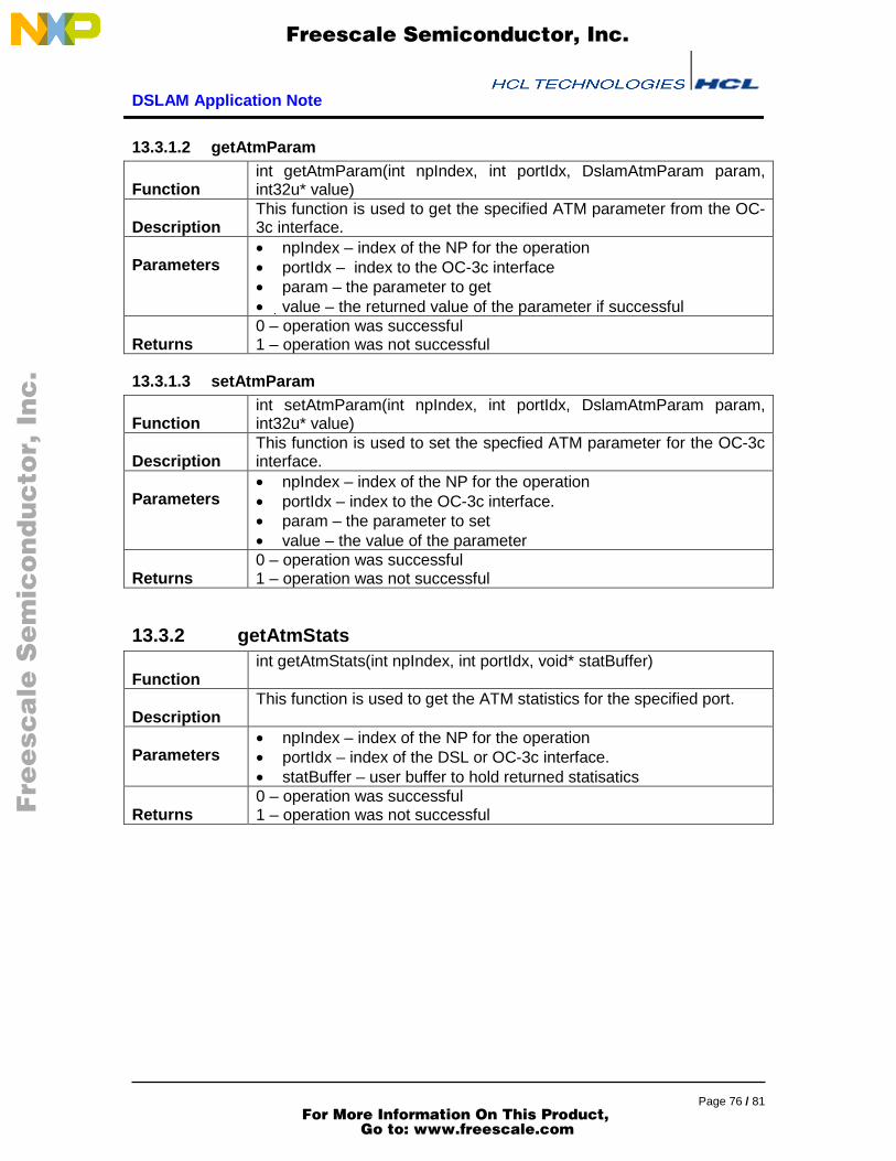
DSLAM Application Note
Page 76 / 81
13.3.1.2 getAtmParam
Functionint getAtmParam(int npIndex, int portIdx, DslamAtmParam param,int32u* value)
DescriptionThis function is used to get the specified ATM parameter from the OC-3c interface.
Parameters• npIndex – index of the NP for the operation• portIdx – index to the OC-3c interface• param – the parameter to get• �value – the returned value of the parameter if successful
Returns0 – operation was successful1 – operation was not successful
13.3.1.3 setAtmParam
Functionint setAtmParam(int npIndex, int portIdx, DslamAtmParam param,int32u* value)
DescriptionThis function is used to set the specfied ATM parameter for the OC-3cinterface.
Parameters• npIndex – index of the NP for the operation• portIdx – index to the OC-3c interface.• param – the parameter to set• value – the value of the parameter
Returns0 – operation was successful1 – operation was not successful
13.3.2 getAtmStats
Functionint getAtmStats(int npIndex, int portIdx, void* statBuffer)
DescriptionThis function is used to get the ATM statistics for the specified port.
Parameters• npIndex – index of the NP for the operation• portIdx – index of the DSL or OC-3c interface.• statBuffer – user buffer to hold returned statisatics
Returns0 – operation was successful1 – operation was not successful
F
ree
sca
le S
em
ico
nd
uc
tor,
I
Freescale Semiconductor, Inc.
For More Information On This Product, Go to: www.freescale.com
nc
...

DSLAM Application Note
Page 77 / 81
13.4 FR API
This section lists the API available on the host for configuring and maintaining FR links.
13.4.1 Data Types
13.4.1.1 DslamFrParam
DescriptionThis structure contains an enumeration of the supported FRparameters.
Typeenum
UsageThe definition for the fields of this structure are as follows:• mru - maximum received unit size that can be received on this link.
13.4.1.2 getFrParam
Functionint getFrParam(int npIndex, int portIdx, DslamFrParam param, int32u*value)
DescriptionThis function is used to get the specified FR parameter from the FRLink
Parameters• npIndex – index of the NP for the operation• portIdx – index to DSL or OC-3c interface• param – the parameter to get• �value – the returned value of the parameter if successful
Returns0 – operation was successful1 – operation was not successful
13.4.1.3 setFrParam
Functionint setFrParam(int npIndex, int portIdx, DslamFrParam param, int32u*value)
DescriptionThis function is used to set the specified FR parameter on the FR Link
Parameters• npIndex – index of the NP for the operation• portIdx – index to DSL or OC-3c interface.• param – the parameter to set• value – the value of the parameter
Returns0 – operation was successful1 – operation was not successful
13.4.1.4 getFrStats
Functionint getFrStats(int npIndex, int portIdx, void* statBuffer)
F
ree
sca
le S
em
ico
nd
uc
tor,
I
Freescale Semiconductor, Inc.
For More Information On This Product, Go to: www.freescale.com
nc
...

DSLAM Application Note
Page 78 / 81
DescriptionThis function is used to get the FR port statistics from the specified FRLink.
Parameters• npIndex – index of the NP for the operation• portIdx – index to DSL or OC-3c interface• statBuffer – user buffer to hold returned statisatics
Returns0 – operation was successful1 – operation was not successful
13.5 Control APIThis section lists the API available on the host for control the applications andprocessing their outputs.
13.5.1 Functions
13.5.1.1 startDslamLineCardFunction int startDslamLineCard(int32u npIndex,
int8u fabricId,int(*rxIP)(int,int32u,void*,int16u,int8u*),int(*rxATM)(int,int32u,void*,int16u,int8u*),int(*rxFR)(int,int32u,void*,int16u,int8u*),int defaultConfig))
DescriptionThis function is used to start the DSLAM Line Card application
Parameters• npIndex – index of the NP for the operation• fabricId – fabricId• rxIP – IP upcall function pointer• rxATM – ATM upcalll function pointer• rxFR – FR upcalll function pointer• defaultConfig – if set, a default link/channel configuration and table
contents are loadedReturns 0 – operation was successful
1 – operation was not successfulImplementation NULL pointers are allowed for the upcalls.
13.5.1.2 registerIpUpcall
Functionint registerIpUpcall(int32u npIndex,int(*rxIP)(int,int32u,void*,int16u,int8u*))
DescriptionThis function is used to register an IP upcall function once theapplication has been started.
Parameters• npIndex – index of the NP for the operation• rxIP – IP upcall function pointer
Returns0 – operation was successful1 – operation was not successful (an upcall was previously registeredand not de-registered)
F
ree
sca
le S
em
ico
nd
uc
tor,
I
Freescale Semiconductor, Inc.
For More Information On This Product, Go to: www.freescale.com
nc
...

DSLAM Application Note
Page 79 / 81
13.5.1.3 registerAtmUpcall
Functionint registerAtmUpcall(int32u npIndex,int(*rxATM)(int,int32u,void*,int16u,int8u*))
DescriptionThis function is used to register an ATM upcall function once theapplication has been started.
Parameters• npIndex – index of the NP for the operation• rxATM – ATM upcall function pointer
Returns0 – operation was successful1 – operation was not successful (an upcall was previouslyregistered and not de-registered)
13.5.1.4 registerFrUpcall
Functionint registerFrUpcall(int32u npIndex,int(*rxFR)(int,int32u,void*,int16u,int8u*))
DescriptionThis function is used to register an FR upcall function once theapplication has been started.
Parameters• npIndex – index of the NP for the operation• rxFR – FR upcall function pointer
Returns0 – operation was successful1 – operation was not successful (an upcall was previously registeredand not de-registered)
13.5.1.5 deregisterIpUpcall
Functionint deregisterIpUpcall(int32u npIndex)
DescriptionThis function is used to de-register an IP upcall function once theapplication has been started.
Parameters• npIndex – index of the NP for the operation
Returns0 – operation was successful1 – operation was not successful
13.5.1.6 deregisterAtmUpcall
Functionint deregisterAtmUpcall(int32u npIndex)
DescriptionThis function is used to de-register an ATM upcall function once theapplication has been started.
Parameters• npIndex – index of the NP for the operation
Returns0 – operation was successful1 – operation was not successful
13.5.1.7 deregisterFrUpcall
Functionint deregisterFrUpcall(int32u npIndex)
F
ree
sca
le S
em
ico
nd
uc
tor,
I
Freescale Semiconductor, Inc.
For More Information On This Product, Go to: www.freescale.com
nc
...
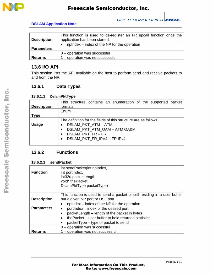
DSLAM Application Note
Page 80 / 81
DescriptionThis function is used to de-register an FR upcall function once theapplication has been started.
Parameters• npIndex – index of the NP for the operation
Returns0 – operation was successful1 – operation was not successful
13.6 I/O APIThis section lists the API available on the host to perform send and receive packets toand from the NP.
13.6.1 Data Types
13.6.1.1 DslamPktType
DescriptionThis structure contains an enumeration of the supported packetformats.
TypeEnum
UsageThe definition for the fields of this structure are as follows:• DSLAM_PKT_ATM – ATM• DSLAM_PKT_ATM_OAM – ATM OA&M• DSLAM_PKT_FR – FR• DSLAM_PKT_FR_IPV4 – FR IPv4
13.6.2 Functions
13.6.2.1 sendPacket
Functionint sendPacket(int npIndex,int portIndex,int32u packetLength,void* thePacket,DslamPktType packetType)
DescriptionThis function is used to send a packet or cell residing in a user bufferout a given NP port or DSL port.
Parameters• npIndex – index of the NP for the operation• portIndex – index of the desired port• packetLength – length of the packet in bytes• thePacket – user buffer to hold returned statistics• packetType – type of packet to send
Returns0 – operation was successful1 – operation was not successful
F
ree
sca
le S
em
ico
nd
uc
tor,
I
Freescale Semiconductor, Inc.
For More Information On This Product, Go to: www.freescale.com
nc
...

DSLAM Application Note
Page 81 / 81
14 Appendix – Optimizations done in the application
Reason for allocation of different clusters functioning for DSL and OC-3cinterfacesDSLAM application logically configures CPs to serve to DSL cluster and OC-3c cluster.CP8 and CP9 perform segmentation and reassembly, respectively, for the M-2 MPHYchunks received at DSL cluster (cluster 0). While CP10 and CP11 are for packetsreceived at OC-3c cluster. Similarly, CP12 and CP13 do IP and FR processing,respectively, for M-2 MPHY chunks received at DSL cluster. Packets received at OC-3cinterfaces will be queued to CP14 and CP15 for IP and FR processing.
The reason for this, is the data rate at which the packets are received at DSL interfaces.For downstream traffic, the rate required is 864 Mbps (9 Mbps per 96 DSL ports). Tocater to this bandwidth, the reassembly, segmentation and IP processing cannot handletraffic from both OC-3c and DSL interfaces at the same time.
Reason for doing FR DLCI lookup FR input threadIn the case of FR packets, DLCI lookup is launched in CPRC. This is because if thelookup is launched from RxSDP, the utilization of the re-circulation CP for FR is affectedbecause it does the FR DLCI lookup alone and then FR encapsulation (modification ofxisting FR header information) cannot be done in the same CP.
F
ree
sca
le S
em
ico
nd
uc
tor,
I
Freescale Semiconductor, Inc.
For More Information On This Product, Go to: www.freescale.com
nc
...