patella planing system - home - zwan the need for manual completion of patellar resurfacing. the...
TRANSCRIPT

Patella Planing System
REFERENCE GUIDE
AND
SURGICAL TECHNIQUE
AN ONLAY
PATELLA PREPARATION
SYSTEM
INSTRUMENTSSPECIALIST®


TECHNIQUE FOR PRIMARY PATELLAR RESURFACING
ACCURATE, REPRODUCIBLE
RESECTION
Designed to minimize bone removal andrestore preoperative patellar height preciselythrough a series of reproducible steps.
MODULAR INSTRUMENTS
Completely modular, offering maximumintraoperative flexibility in choosing sizesand patellar configurations.
FULL COMPATIBILITY WITH
ALL RESURFACED P.F.C. SIGMA
PATELLAR IMPLANTS
Fully compatible with all single-peg, three-peg, oval and dome P.F.C.® Sigma Patellarimplants, offering a maximum number ofintraoperative choices.
SINGLE-USE PLANER BLADES
AND DRILL BITS
Designed for single-patient use, the dispos-able planer blades and drill bits offer consis-tently sharp cutting surfaces that facilitatebone cut reproducibility, reduce bone traumacaused by dull planers or sawblades and min-imize the need for manual completion ofpatellar resurfacing.
The Specialist® 2 Patellar Planer System
Instruments offer a simple, reproducible
and accurate approach to patellar
resurfacing. The instrumentation is
designed to accurately reproduce
preoperative patellar thickness without
time-intensive measuring and recutting
of patellar bone.
BY CLIFFORD W. COLWELL JR., MDMedical Director of Scripps Clinic
Center of Orthopaedic Research and Education
Shiley Professor of Musculoskeletal Diseases
Medical Director, Musculoskeletal Center
Scripps Clinic, La Jolla, Calif.
1

EXPOSING THE PATELLA
2
Following completion of all femoral and tibialcuts, and with trials in position, place the knee infull extension and evert the patella laterally.Remove peripheral osteophytes. Expose the anterior or prepatellar surface to ensure that thepatellar clamp can grasp the ventral patellar sur-face without interposition of skin. It is importantthat sufficient exposure of the patella is achieved to position a caliper on the anterior and posteriorsurfaces. [fig. 1]
[figure 1]

MEASURING PATELLAR HEIGHT
Position the arms of the patellar caliper overthe highest anteroposterior (A/P) point of thepatella, usually the median ridge. This willmeasure the preoperative patellar height (the normal range is 20-30 mm). It will later
correspond with the final postoperative height,generally to within +/- 1 mm. Note patellarheight and remove the caliper. If the patellarthickness is less than 20 mm, a full planing ofthe patella may not be possible. [fig. 2]
3
[figure 2]

4
SIZING THE PATELLA
Select a template that most adequately coversthe articular surface of the patella. The size ofthe template selected will dictate the level ofbone to be resected. [fig. 3]
The template size will also correspond to thedepth gauge size that will be used when settingthe planing depth. [see fig. 12]
Template Patella Implant
28 mm 7 mm
32 mm 8 mm
35 mm 8.5 mm
38 mm 9 mm
41 mm 11.5 mm
See chart on page 12
Choose the planer sleeve that best approximatesthe outer diameter of the patella. The sleeveshould tightly border the patellar border with lessthan 1-2 mm between the inner rim of the sleeveand the patella. [fig. 4]
[figure 3]
[figure 4]

THE PATELLAR CLAMP
ASSEMBLING THE PLANER SLEEVE
Assemble the selected planer sleeve (small, mediumor large) to the patellar clamp by snapping the maleconnector of the sleeve into the female connector of the clamp. Take care to ensure that the teeth of the sleeve face down toward the patella.[fig. 5]
PLACING THE PATELLAR CLAMP
AND PLANER SLEEVE
Position the patellar clamp/planer sleeve assemblyaround the patella. Orient the sleeve by clampingonto the soft tissue of the rectus tendon and thepatellar tendon, as well as the soft tissue of themedial and lateral retinaculum. [fig. 6] Take care to ensure that the patella is held tightly within theclamp without flexion or laxity. View the clamp’sposition in profile to ensure a balanced and sym-metric patellar resection. [fig. 7] Once alignment isassured, close the clamp and lock into place usingits tightening screw.
5
[figure 5]
[figure 6]
[figure 7]

ASSEMBLING THE PLANER
Assemble a planer blade and a drill bit onto theappropriately sized planer body (the planer’sblade size should match the planer sleeve):
a) Slide the blade into the slots on theplaner body as indicated by the insertion arrow on the body. The side of the blade indicating size should present itself outward. [fig. 8]
b) Using gauze to protect gloves from acut, assemble the drill bit through thecentral hole of the blade and into thecentral hole of the body while simulta-neously depressing the black button on the side of the body. [fig. 9]
c) Once the drill bit is firmly seated,release the black button and rotate the drill bit approximately 90 degreesclockwise with a forcep until it locksinto place. The black button should pop out into the full “out” position.[fig. 9]
To disassemble a blade and a drill bit from aplaner body, take the following disassemblysteps:
a) Depress the black button on the side of the planer body while grasping theside of the drill bit with forceps andslide the drill bit out of the planerbody. Release the black button.
b) Grasp the blade with forceps and slideit out of the planer body in the direc-tion opposite that shown by the arrowon the planer body.
6
[figure 8]
[figure 9]
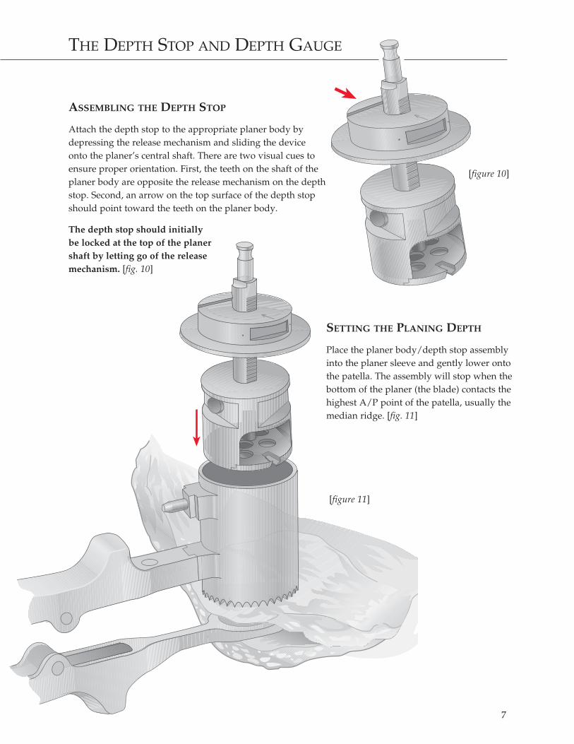
ASSEMBLING THE DEPTH STOP
Attach the depth stop to the appropriate planer body bydepressing the release mechanism and sliding the deviceonto the planer’s central shaft. There are two visual cues toensure proper orientation. First, the teeth on the shaft of theplaner body are opposite the release mechanism on the depthstop. Second, an arrow on the top surface of the depth stopshould point toward the teeth on the planer body.
The depth stop should initially be locked at the top of the planer shaft by letting go of the release mechanism. [fig. 10]
SETTING THE PLANING DEPTH
Place the planer body/depth stop assemblyinto the planer sleeve and gently lower ontothe patella. The assembly will stop when thebottom of the planer (the blade) contacts thehighest A/P point of the patella, usually themedian ridge. [fig. 11]
7
[figure 11]
THE DEPTH STOP AND DEPTH GAUGE
[figure 10]
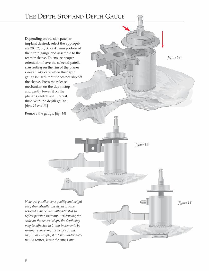
Depending on the size patellarimplant desired, select the appropri-ate 28, 32, 35, 38 or 41 mm portion ofthe depth gauge and assemble to thereamer sleeve. To ensure proper orientation, have the selected patellasize resting on the rim of the planersleeve. Take care while the depthgauge is used, that it does not slip offthe sleeve. Press the release mechanism on the depth stop and gently lower it on the planer’s central shaft to rest flush with the depth gauge. [figs. 12 and 13]
Remove the gauge. [fig. 14]
Note: As patellar bone quality and heightvary dramatically, the depth of boneresected may be manually adjusted toreflect patellar anatomy. Referencing thescale on the central shaft, the depth stopmay be adjusted in 1 mm increments byraising or lowering the device on theshaft. For example, if a 1 mm underresec-tion is desired, lower the ring 1 mm.
THE DEPTH STOP AND DEPTH GAUGE
8
[figure 12]
[figure 14]
[figure 13]

PLANING THE PATELLA
Irrigate the planing site with sterile saline solu-tion. Assemble power to the planer body, raisethe planer slightly above the patellar surfaceand bring the planer to full speed. Firmlyadvance the planer into the patellar surface until the depth stop’s collar is seatedflush on the planer sleeve. [figs. 15 and 16]
Note: It is important that the planer is at full speedprior to touching the patella to avoid capturebetween the planer and the bone. If capture occurs,immediately reverse power and lift the planer off thepatellar bone before planing is resumed.
After planing is complete, remove the planerassembly from the sleeve, loosen the clamp’stightening screw and remove the clamp.
9
[figure 15]
[figure 16]

VERIFYING HEIGHT AND PREPARING THE PEGS
Verify patellar thickness using the patellarcaliper. The height of the patella, plus theimplant, should be within +/- 1 mm of the pre-operative height unless intentional under oroverresection was elected. Remove residualmarginal osteophytes.
Assemble the template to the patellar clamp.Align the template with the patellar surface inthe desired position, close the clamp and lockinto place with the template snug against theplaned surface. The clamp’s tightening screwshould be securely closed. Advance the patellardrill through the template’s drill holes until
positive stop is obtained. Prepare the peg holes.Loosen the clamp’s tightening screw andremove the clamp. Assemble the appropriatepatellar trial to the patellar surface and reducethe patella into the trochlea for trial from 0degrees of extension to 120 degrees of flexion. If a lateral retinacular release is required, it maybe done at this time. [fig. 17]
Note: It is important to ensure that marginal osteo-phytes or residual patellar bone facets do not contactthe anterior flange of the femoral component duringtrial reduction.
10
[figure 17]

CEMENTING THE IMPLANT
Note: This step may be done in conjunction with thecementing of the tibial and femoral components orindependently if desired.
Remove the trial implant, cleanse the preparedbed with pulsatile lavage, and adequately drythe bony surface. Apply methyl methacrylatebone cement using digital pressure to assureadequate penetration into the cancellous bone.Implant the appropriate P.F.C. Sigma patellarcomponent. Apply digital pressure to the domeof the implant to remove extraneous cement.
Give careful attention to ensure correct patellaralignment and peg seating relative to the patellarsurface.
Assemble the cementing clamp head to the patellarclamp, align the head with the patellar implant,and close the clamp and lock into place. Securelyclose the clamp’s tightening screw to ensure properimplant seating and cement pressurization. Care-fully remove extruded cement with a curette. [fig. 18]
Once the cement has polymerized, loosen the tight-ening screw and remove the clamp. Inspect theimplant and confirm its height using the patellarcaliper. Remove any remaining extruded cement.
11
[figure 18]

PATELLAR DIMENSIONS
P.F.C. SIGMA PATELLA OPTIONS
3-Post Dome Patella
Dimension Dimension DimensionDescription A B C
Round and Oval, 32 mm 5.0 7.8 12.9
Round and Oval, 35 mm 5.0 8.5 13.6
Round and Oval, 38 mm 5.0 9.1 14.2
Round and Oval, 41 mm 5.0 11.4 16.5
1-Post Dome Patella
Round, 28 mm 5.7 7.2 13.0
Round and Oval, 32 mm 6.2 7.8 14.0
Round and Oval, 35 mm 6.2 8.5 14.7
Round and Oval, 38 mm 7.2 9.1 16.3
Round and Oval, 41 mm 7.2 11.4 18.6
3-Post Dome Patella 1-Post Dome Patella
12
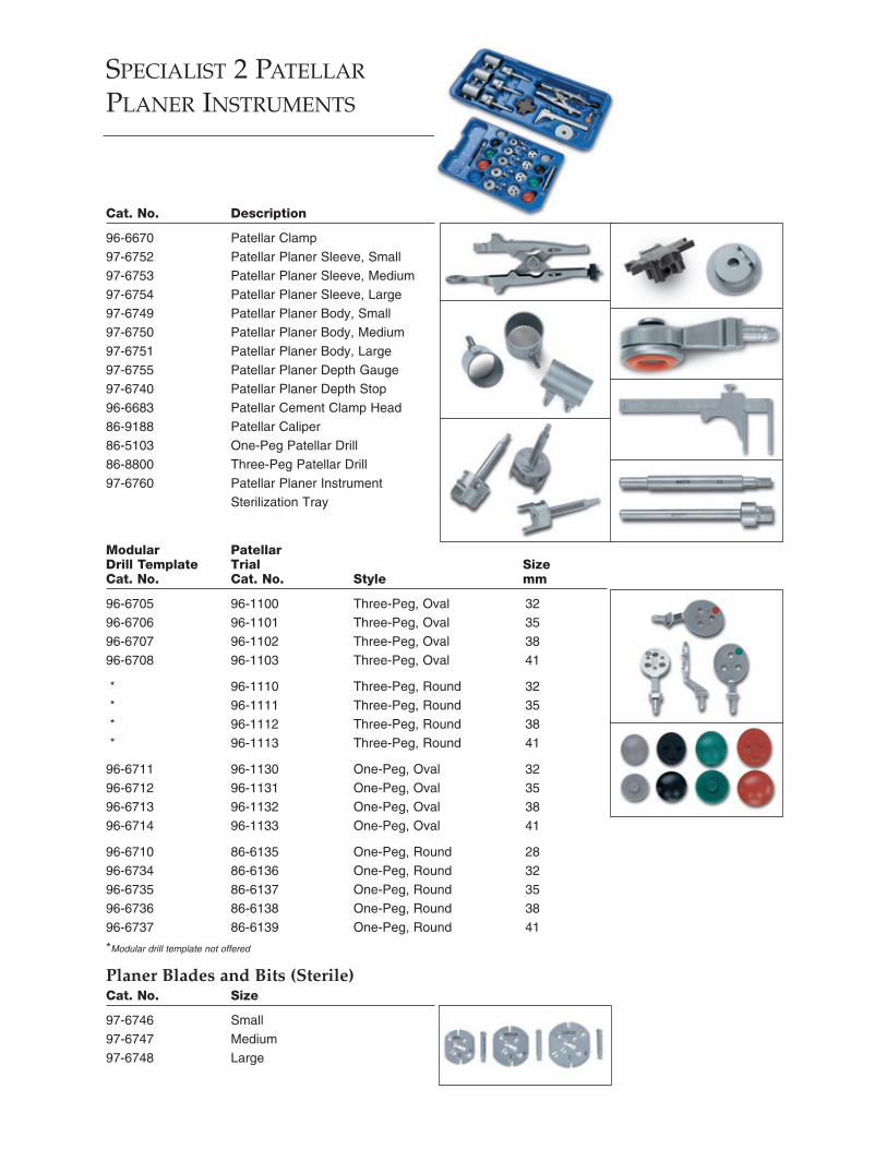
SPECIALIST 2 PATELLAR
PLANER INSTRUMENTS
Cat. No. Description
96-6670 Patellar Clamp97-6752 Patellar Planer Sleeve, Small97-6753 Patellar Planer Sleeve, Medium97-6754 Patellar Planer Sleeve, Large97-6749 Patellar Planer Body, Small97-6750 Patellar Planer Body, Medium97-6751 Patellar Planer Body, Large97-6755 Patellar Planer Depth Gauge97-6740 Patellar Planer Depth Stop96-6683 Patellar Cement Clamp Head86-9188 Patellar Caliper86-5103 One-Peg Patellar Drill86-8800 Three-Peg Patellar Drill97-6760 Patellar Planer Instrument
Sterilization Tray
Modular PatellarDrill Template Trial SizeCat. No. Cat. No. Style mm
96-6705 96-1100 Three-Peg, Oval 3296-6706 96-1101 Three-Peg, Oval 3596-6707 96-1102 Three-Peg, Oval 3896-6708 96-1103 Three-Peg, Oval 41
* 96-1110 Three-Peg, Round 32* 96-1111 Three-Peg, Round 35* 96-1112 Three-Peg, Round 38* 96-1113 Three-Peg, Round 41
96-6711 96-1130 One-Peg, Oval 3296-6712 96-1131 One-Peg, Oval 3596-6713 96-1132 One-Peg, Oval 3896-6714 96-1133 One-Peg, Oval 41
96-6710 86-6135 One-Peg, Round 2896-6734 86-6136 One-Peg, Round 3296-6735 86-6137 One-Peg, Round 3596-6736 86-6138 One-Peg, Round 3896-6737 86-6139 One-Peg, Round 41
*Modular drill template not offered
Planer Blades and Bits (Sterile)Cat. No. Size
97-6746 Small97-6747 Medium97-6748 Large

1.5M11020601-45-050 (Rev. 1)
Printed in USA.©2000 DePuy Orthopaedics, Inc. All rights reserved.
For more information about DePuy products, visit our web site at www.jnjgateway.com.Abearingknees.com