past, present, and future: nanopipette applications to
TRANSCRIPT

Past, Present, and Future: Nanopipette Applications to Single Cell Analysis Erick Froede, Michael Rothenbergrer Fall Semester 2011 ME597C Abstract
This paper reviews the broad area of nanopipettes by describing the different types, what each type is capable of, and which one is most suitable for use in intracellular injections and cell surgery. It also provides a look forward at which fields nanopipettes are most likely to impact the most. This analysis will compare features such as methods of fabrication, complexity of design, mechanical properties, and electrical properties. The focus of this paper is to present a brief overview of both glass and carbon nanopipettes, while proving that carbon based nanopipettes are the best design for intracellular applications. Introduction
Nanotechnology has been a rapidly expanding field and recently has presented many solutions on a small scale for biomedical applications, such as cell surgery.1-3 Biologists and chemists have been using micropipettes to deliver very specific volumes of fluid in the microliter range since the 1960s. These tools were designed when scientists became interested in working on the molecular level and needed to have instruments that were more accurate and precise for their experiments. By miniaturizing pipettes to a micro scale they were able to achieve these new requirements as well as increased electrical sensitivity.4 Micropipettes had the ability to perform microinjection into living cells, accomplish cell biopsies, and also analyze the electrophysiology of cells by using the pipette as a probe.5 While micropipettes advanced the research in molecular biology and cell analysis, they had the unwanted potential to kill the cells they were injecting into and still had other limitations because of their tip size.6
The solution to these limitations came when the capability to create reproducible nano-sized pipettes was realized in 2000.3A nanopipette is defined as a pipette that has tip diameters ranging from tens to hundreds of nanometers.4
The basic shape of a nanopipette is shown below in Figure 1 (A) and (B) with a diagram of what the pipette’s tip, shoulder, and
stem are in (A). This diagram will be useful during later descriptions of pipette dimensions to help visualize what is being described as well as (C) to differentiate between the inner and outer diameter of the nanopipette tip.4 Transition electron microscopy (TEM), among other nano-scale observation methods, was able to do detailed investigations of the structure of these nanopipettes and indicated that the potential precision, accuracy, and sensitivity had increased greatly over micropipettes.7 As the nanopipette tip shrank into the nanometer range, it became viable to apply an electric potential across the tip to trap negatively charged particles. If this potential was reversed in polarity, then the particles held within the nanopipette would have been forced out and delivered to their destination.5
The shape of nanopipettes allowed them to be used in the current equipment designed for micropipettes. By having a small diameter tip in the nano range that increased into a large diameter stem in the macro range, nanopipettes could have been attached to micromanipulators and fluid injectors without any physical modification or adapters.8
As these fabrication processes became more reliable, the potential to create less invasive surgical tools out of nanopipettes became a manufacturing goal. There was a need to refine these processes so that they were not so complicated that it would be infeasible to reproduce them outside of the research environment, and also so that these devices would be safe in biological applications. As the fabrication time for carbon nanotubes began to decrease compared to glass based nanopipettes, there was the potential to use these tubes as probes or devices to transport fluid through their hollow passageways.7,9
Figure 1: (A) Illustration of a nanopipette denoting the stem, shoulder, shank, and tip. (B) Optical micrograph of a nanopipette filled with dye for visualization. (C) Scanning electron micrograph of a nanopipette in end-on view. The nanopore opening at the tip is visible.4
Nano and Scaling Effects
2
On the nano scale, a number of physical properties which
are taken for granted on the macro scale, begin to exhibit unexpected and sometimes counterintuitive behaviors. Specifically regarding nanopipettes, there are a few key mechanical, electrical, and thermal properties which dominate current applications or have the potential to influence future developments. For example, bending stiffness is a critical factor when it comes to penetrating cells and decreases proportionally to size, allowing a nanopipette to potentially buckle rather than break when encountering resistive forces. Furthermore, resistance and power density increase as size decreases, leading to unique advantages when it comes to heat production and electrical potency at the cellular level. Additionally, conductive heat transfer increases with size reductions, allowing heat to be dissipated away from the nanopipette and into its surroundings efficiently. Lastly, smaller size imparts further advantages in dynamic range, sensitivity, accuracy and reliability. There are many more relationships to be considered, and this is only a selective listing which is summarized below in Table 1.10 Table 1: Select Properties and Respective Size Dependence10
Property Size Dependence
Bending Stiffness L
Resistance 1/L
Power Density 1/L
Conductive Heat Transfer General Improvement
Dynamic Range
Sensitivity
Accuracy
Reliability
Glass Based Nanopipettes
Nanopipettes made of glass are one of the main types of pipette that are being fabricated today. These pipettes are similar in nature to the glass micropipettes that chemists and biologists have been using for decades and are formed by heating a glass capillary in a specific region with either gas heat or laser radiation.11 While the glass is being heated, a
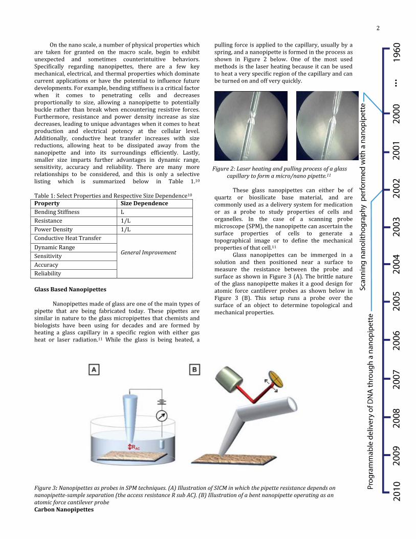
pulling force is applied to the capillary, usually by a spring, and a nanopipette is formed in the process as shown in Figure 2 below. One of the most used methods is the laser heating because it can be used to heat a very specific region of the capillary and can be turned on and off very quickly.
Figure 2: Laser heating and pulling process of a glass capillary to form a micro/nano pipette.11
These glass nanopipettes can either be of
quartz or biosilicate base material, and are commonly used as a delivery system for medication or as a probe to study properties of cells and organelles. In the case of a scanning probe microscope (SPM), the nanopipette can ascertain the surface properties of cells to generate a topographical image or to define the mechanical properties of that cell.11
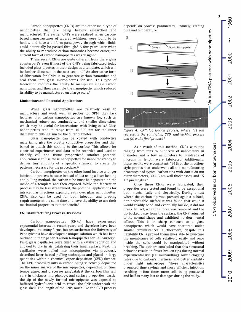
Glass nanopipettes can be immerged in a solution and then positioned near a surface to measure the resistance between the probe and surface as shown in Figure 3 (A). The brittle nature of the glass nanopipette makes it a good design for atomic force cantilever probes as shown below in Figure 3 (B). This setup runs a probe over the surface of an object to determine topological and mechanical properties.
Figure 3: Nanopipettes as probes in SPM techniques. (A) Illustration of SICM in which the pipette resistance depends on nanopipette-sample separation (the access resistance R sub AC). (B) Illustration of a bent nanopipette operating as an atomic force cantilever probeCarbon Nanopipettes
3
Carbon nanopipettes (CNPs) are the other main type of
nanopipettes that are being heavily researched and manufactured. The earlier CNPs were realized when carbon-based nanostructures of tapered whiskers were found to be hollow and have a uniform passageway through which fluids could potentially be passed through.7 A few years later when the ability to reproduce carbon nanotubes became easier, the current form of carbon nanopipettes was designed.
These recent CNPs are quite different from there glass counterpart’s even if most of the CNPs being fabricated today included glass pipettes in their design as a template, which will be further discussed in the next section.12 An alternative form of fabrication for CNPs is to generate carbon nanotubes and seal them into glass micropipettes for use. This type of fabrication requires the ability to manipulate single carbon nanotubes and then assemble the nanopipette, which reduced its ability to be manufactured on a large scale.9 Limitations and Potential Applications
While glass nanopipettes are relatively easy to manufacture and work well as probes for SPM, they lack features that carbon nanopipettes are known for, such as mechanical robustness, conductivity, and smaller dimensions which may be useful for interactions with living cells.1 Glass nanopipettes tend to range from 10-200 nm for the inner diameter to 200-500 nm for the outer diameter.
Glass nanopipette can be coated with conductive material to give the pipette conductive properties and then baked to attach this coating to the surface. This allows for electrical experiments and data to be recorded and used to identify cell and tissue properties.8 Another potential application is to use these nanopipettes for nanolithography to deliver tiny amounts of a specific chemical to create the patterns necessary for the procedure.13
Carbon nanopipettes on the other hand involve a longer fabrication process because instead of just using a laser heating and pulling method, the carbon tube must be deposited on the inside of a template and then exposed. While the fabrication process may be less streamlined, the potential applications for intracellular injections expand greatly over glass nanopipettes. CNPs also can be used for both injection and probing requirements at the same time and have the ability to use their mechanical properties to their benefit.1
CNP Manufacturing Process Overview
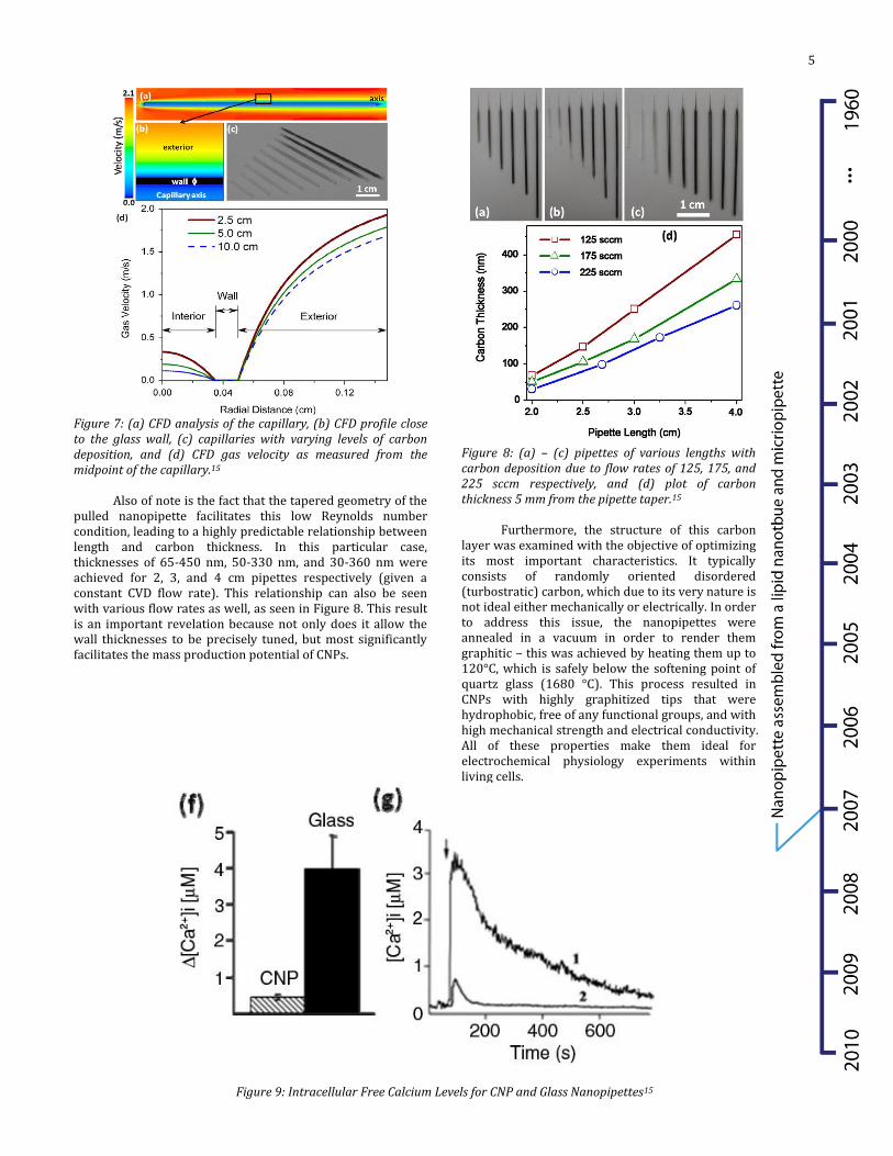
Carbon nanopipettes (CNPs) have experienced exponential interest in recent years and therefore have been developed into many forms, but researchers at the University of Pennsylvania have developed a unique solution which has been outlined in their paper “Carbon Nanopipettes for Cell Surgery”. First, glass capillaries were filled with a catalyst solution and allowed to dry in air, catalyzing their inner surface. Next, the capillaries were pulled into micropipettes via previously described laser heated pulling techniques and placed in large quantities within a chemical vapor deposition (CVD) furnace. The CVD process results in carbon being selectively deposited on the inner surface of the micropipettes; depending on time, temperature, and precursor gas/catalyst the carbon film will vary in thickness, morphology, and surface properties. Lastly, the tip of the newly formed micropipette was exposed to buffered hydrofluoric acid to reveal the CNP underneath the glass shell. The length of the CNP, much like the CVD process,
depends on process parameters - namely, etching time and temperature.
Figure 4: CNP fabrication process, where (a) i-iii represents the catalyzing, CVD, and etching process and (b) is the final product.1
As a result of this method, CNPs with tips
ranging from tens to hundreds of nanometers in diameter and a few nanometers to hundreds of microns in length were fabricated. Additionally, these results were consistent: “95% of the injection-style probes that underwent all the manufacturing processes had typical carbon tips with 200 ± 20 nm outer diameters, 30 ± 5 nm wall thicknesses, and 15 ± 2 µm lengths.”
Once these CNPs were fabricated, their properties were tested and found to be exceptional both mechanically and electrically. During a test where the carbon tip was pressed against a hard, non-deformable surface it was found that while it would readily bend and eventually buckle, it did not break. In fact, when the force was removed and the tip backed away from the surface, the CNP returned to its normal shape and exhibited no detrimental effects. This is in sharp contrast to a glass nanopipette, which would have shattered under similar circumstances. Furthermore, despite this flexibility CNPs proved themselves able to puncture the membranes of cells relatively easily and once inside the cells could be manipulated without breaking. The authors concluded that this structural behavior results in fewer broken tips during normal experimental use (i.e. mishandling), lower clogging rates due to carbon’s inertness, and better visibility under light microscopy. These characteristics promoted time savings and more efficient injection, resulting in four times more cells being processed and half as many lost to damages during the study.

4
Figure 5: CNP testing process, where (a) represents the hard surface bending/buckling test and (b) the cell puncture test.1
As for electrical properties, the carbon lining the inside
of the quartz micropipette enabled the CNP to conduct electricity along the length of its structure, from nano-scale tips to macroscopic tails. This electrical detection function is sensitive and robust, as proven during a cell electrophysiology study. For the purpose of the study, the CNP tip was inserted into the membrane of the cell and used to measure the resting potential of the cell and any variations in the potential due to external stimuli. When no stimuli were present a reasonably
membrane potential was recorded, and upon the introduction of a pharmacological stimulant changes were also reliably registered. Interestingly, the electrical capability of the CNP extended beyond the cell membrane as well, due to the discovery that when the tip was brought in close proximity to the cell a small increase in potential was observed, followed by a large decrease upon penetration. The authors concluded that in addition to a multitude of electrophysiology applications, the CNP can be used sense when the cell is punctured and therefore automate the cell injection process.14
In addition to the group working at the University of Pennsylvania, there are researchers at Drexel University pursuing similar CNP technology. Their fabrication method is nearly identical, making use of pulled capillaries, CVD, and wet etching to produce nanopipettes but they advance the technical understanding of the process significantly. First, they performed a computational fluid dynamics (CFD) analysis on the CVD process, which was of interest due to lack of a metal catalyst on the glass surface to facilitate the initial deposition of carbon; rather, they rely on molecular collision as the only source of activation. It was discovered that when very low Reynolds number conditions (Re < 10) exist within the nanopipette, long residence times and therefore large numbers of collisions occur, helping bring the molecules to a high energy state and overcome the activation energy associated with decomposition. In addition, the occurrence of spontaneous nucleation that leads to sooting and deposition of a non-uniform carbon layer was absent, indicating this process is feasible.
Figure 6: Cell Electrophysiology, where (a) represents cell membrane penetration and (b) recorded potential.1
5
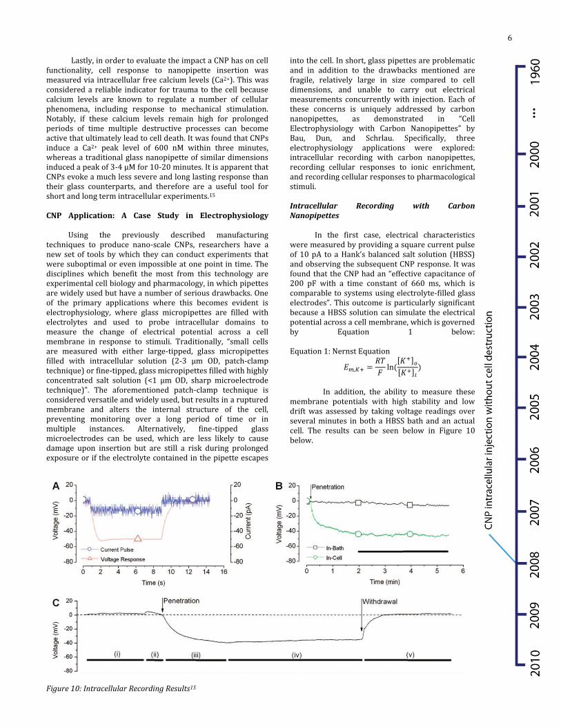
Figure 7: (a) CFD analysis of the capillary, (b) CFD profile close to the glass wall, (c) capillaries with varying levels of carbon deposition, and (d) CFD gas velocity as measured from the midpoint of the capillary.15
Also of note is the fact that the tapered geometry of the
pulled nanopipette facilitates this low Reynolds number condition, leading to a highly predictable relationship between length and carbon thickness. In this particular case, thicknesses of 65-450 nm, 50-330 nm, and 30-360 nm were achieved for 2, 3, and 4 cm pipettes respectively (given a constant CVD flow rate). This relationship can also be seen with various flow rates as well, as seen in Figure 8. This result is an important revelation because not only does it allow the wall thicknesses to be precisely tuned, but most significantly facilitates the mass production potential of CNPs.
Figure 8: (a) – (c) pipettes of various lengths with carbon deposition due to flow rates of 125, 175, and 225 sccm respectively, and (d) plot of carbon thickness 5 mm from the pipette taper.15
Furthermore, the structure of this carbon
layer was examined with the objective of optimizing its most important characteristics. It typically consists of randomly oriented disordered (turbostratic) carbon, which due to its very nature is not ideal either mechanically or electrically. In order to address this issue, the nanopipettes were annealed in a vacuum in order to render them graphitic – this was achieved by heating them up to 120°C, which is safely below the softening point of quartz glass (1680 °C). This process resulted in CNPs with highly graphitized tips that were hydrophobic, free of any functional groups, and with high mechanical strength and electrical conductivity. All of these properties make them ideal for electrochemical physiology experiments within living cells.
Figure 9: Intracellular Free Calcium Levels for CNP and Glass Nanopipettes15
6
Lastly, in order to evaluate the impact a CNP has on cell
functionality, cell response to nanopipette insertion was measured via intracellular free calcium levels (Ca2+). This was considered a reliable indicator for trauma to the cell because calcium levels are known to regulate a number of cellular phenomena, including response to mechanical stimulation. Notably, if these calcium levels remain high for prolonged periods of time multiple destructive processes can become active that ultimately lead to cell death. It was found that CNPs induce a Ca2+ peak level of 600 nM within three minutes, whereas a traditional glass nanopipette of similar dimensions induced a peak of 3-4 µM for 10-20 minutes. It is apparent that CNPs evoke a much less severe and long lasting response than their glass counterparts, and therefore are a useful tool for short and long term intracellular experiments.15
CNP Application: A Case Study in Electrophysiology Using the previously described manufacturing techniques to produce nano-scale CNPs, researchers have a new set of tools by which they can conduct experiments that were suboptimal or even impossible at one point in time. The disciplines which benefit the most from this technology are experimental cell biology and pharmacology, in which pipettes are widely used but have a number of serious drawbacks. One of the primary applications where this becomes evident is electrophysiology, where glass micropipettes are filled with electrolytes and used to probe intracellular domains to measure the change of electrical potential across a cell membrane in response to stimuli. Traditionally, “small cells are measured with either large-tipped, glass micropipettes filled with intracellular solution (2-3 µm OD, patch-clamp technique) or fine-tipped, glass micropipettes filled with highly concentrated salt solution (<1 µm OD, sharp microelectrode technique)”. The aforementioned patch-clamp technique is considered versatile and widely used, but results in a ruptured membrane and alters the internal structure of the cell, preventing monitoring over a long period of time or in multiple instances. Alternatively, fine-tipped glass microelectrodes can be used, which are less likely to cause damage upon insertion but are still a risk during prolonged exposure or if the electrolyte contained in the pipette escapes
into the cell. In short, glass pipettes are problematic and in addition to the drawbacks mentioned are fragile, relatively large in size compared to cell dimensions, and unable to carry out electrical measurements concurrently with injection. Each of these concerns is uniquely addressed by carbon nanopipettes, as demonstrated in “Cell Electrophysiology with Carbon Nanopipettes” by Bau, Dun, and Schrlau. Specifically, three electrophysiology applications were explored: intracellular recording with carbon nanopipettes, recording cellular responses to ionic enrichment, and recording cellular responses to pharmacological stimuli. Intracellular Recording with Carbon Nanopipettes
In the first case, electrical characteristics were measured by providing a square current pulse of 10 pA to a Hank’s balanced salt solution (HBSS) and observing the subsequent CNP response. It was found that the CNP had an “effective capacitance of 200 pF with a time constant of 660 ms, which is comparable to systems using electrolyte-filled glass electrodes”. This outcome is particularly significant because a HBSS solution can simulate the electrical potential across a cell membrane, which is governed by Equation 1 below: Equation 1: Nernst Equation
[ ] [ ]
In addition, the ability to measure these
membrane potentials with high stability and low drift was assessed by taking voltage readings over several minutes in both a HBSS bath and an actual cell. The results can be seen below in Figure 10 below.
Figure 10: Intracellular Recording Results15

7
In Figure 10 (A), the aforementioned current pulse and voltage response it provokes is represented. As for Figure 10 (B), the CNP was left undisturbed in both mediums, resulting in the authors concluding that drift was minimal; for example, a mean of -61.5 ± 2.97 mV and noise ranging from 1.1 to 1.6 mV rms was found within the cell. Regarding Figure 10 (C), the approach, penetration, and eventual removal of the CNP from a cell is depicted – note the small potential increase right before the CNP punctures the membrane, which showcases the device sensitivity. Recording Cellular Responses to Ionic Enrichment
Once static stability was established, the authors were interested in the CNP’s response to dynamic behavior. Therefore, after the CNP penetrated a cell, several in-situ potassium ion (K+) infusions were made. This ion in particular was used because cell membranes possess a potassium pump, which depending on its activity is responsible for the overall potential gradient; consequently, increasing or decreasing levels lead to hyperpolarization and depolarization, respectively. These experiments can be seen below, in Figure 11.
Figure 11: Ionic Enrichment Results16
Figure 11 (A) depicts the penetration and infusion of 5
nM K+ within a cell, leading to the initial resting potential of -72 mV being subsequently depolarized by 15mV. This single, relatively small disturbance stands in contrast to Figure 11 (B), where a series of 25 mM K+ infusions took place. As can be seen, the resting potential of -68 mV was depolarized by 40 mV in several instances, but nevertheless returned to its original value within approximately 30 seconds. This result was actually highly reproducible over a large number of repetitions, according to the authors. Lastly, in Figure 11 (C) the previous two experiments were combined to illustrate the CNP’s ability to exhibit both sensitivity and range as 5 nM and 15 nM infusions took place. The resting membrane potential of -57 mV was depolarized by 10 mV in the first case, returned to its initial value within 90 seconds, and after a 30 mV depolarization again returned to stable conditions within 90 seconds. Across all of these experiments, it was noted that the potential changes agreed well with Nernst equation predictions.
Recording Cellular Responses to Pharmacological Stimuli
In addition to polarization by the
introduction of ions, it was important that this phenomenon could also be detected via another stimulus – in this case, ɤ-aminobutyric acid (GABA) was used to induce the cell membrane to open Cl- ion channels. It was found that when 12 nM GABA was introduced, a 10 mV hyperpolarization occurred relative to the resting potential of -53 mV, to which the cell returned after 30 seconds. Next, a sequence of ion and pharmacological stimuli were applied, starting with 12 nM GABA and then 15 mM K+, resulting in a 12 mV hyperpolarization and subsequent 25 mV depolarization. In both cases, the resting potential of -57 mV was returned to within 60 seconds. Final Analysis
As demonstrated by the body of research up until this point, CNPs are a powerful new technology that are sure to be a force for change in the field of biomedicine and related disciplines. Key advancements have been made with regards to electrophysiology, functionalization, and biocompatibility as a result of superior physical properties, electrical conduction, and much more. The depth and quality of this development can be seen in the results of Bau et al., as described in the preceding section entitled “CNP Application: A Case Study in Electrophysiology”. Also, the mass production potential demonstrated by Schrlau et al. and outlined in “CNP Manufacturing Process Overview” means this technology has a serious chance of becoming a commercial tool in the near future. Progress and discovery are sure to continue as well, and new uses that will emerge over the next few decades are almost limitless. Based on current trends, there are a number of likely directions: disease detection, cell specific drug delivery, and cell engineering just to name a few. In the first case, as electrophysiology continues to develop it is likely that distinct membrane potentials can be mapped to a specific disease – a “disease fingerprint”, in a sense. Also, since non-destructive cell penetration has been conclusively demonstrated, the latter applications where post manipulation survival rates are necessary become realistic. In conclusion, the past decade has seen exponential growth of the nanopipette and its capabilities in such a way that it proves encouraging that it will continue to advance along the same impressive trajectory. References (1) Schrlau, Michael G., and Haim H. Bau. "Carbon
Nanopipettes for Cell Surgery." Journal of the Association for Laboratory Automation 15.2 (2010): 145-51. Print.
8
(2) Kouklin, N. A., W. E. Kim, A. D. Lazareck, and J. M. Xu.
"Carbon Nanotube Probes for Single-cell Experimentation and Assays." Applied Physics Letters 87.17 (2005): 173901. Print.
(3) Zhang, Bo, Marissa Wood, and Hyunae Lee. "A Silica
Nanochannel and Its Applications in Sensing and Molecular Transport." Analytical Chemistry 81.13 (2009): 5541-548. Print.
(4) Morris, Celeste A., Alicia K. Friedman, and Lane A. Baker.
"Applications of Nanopipettes in the Analytical Sciences." Analyst (2010): 2190-202. Print.
(5) Ying, Liming. "Applications of Nanopipettes in
Bionanotechnology." Biochemical Society Transactions 37 (2009): 702-06. Print.
(6) Schrlau, Michael G., and Haim H. Bau. "Tools for
Nanosurgery: Applying Carbon Nanopipettes to Cell Physiology." Proceedings of the 3rd Frontiers in Biomedical Devices Conference--2008: Presented at the 3rd Frontiers in Biomedical Devices Conference and Exhibition, June 18-20, 2008, Irvine, California, USA. New York: American Society of Mechanical Engineers, 2008. Print.
(7) Mani, Radhika C., Xiang Li, Mahendra K. Sunkara, and
Krishna Rajan. "Carbon Nanopipettes." Nano Letters 3.5 (2003): 671-73. Print.
(8) Vitol, Elina A., Zulfiya Orynbayeva, Michael J. Bouchard,
Jane Azizkhan-Clifford, Gary Friedman, and Yury Gogotsi. "Intracellular Spectroscopy with Surface Enhanced Raman Spectroscopy (SERS)-Enabled Nanopipettes." ACS Nano 3.11 (2009): 3529-536. Print.
(9) Nogawa, K., Tagawa, Y., Nakajima, M., Arai, F., Shimizu,
T., Kamiya, S., Fukuda, T., "Nanopipette with a lipid nanotube as nanochannel," Nanotechnology, 2007. IEEE-NANO 2007. 7th IEEE Conference on , vol., no., pp.1207-1211, 2-5 Aug. 2007.
(10) Wautelet, Michel. "Scaling Laws in the Macro-, Micro-
and Nanoworlds." EUROPEAN JOURNAL OF PHYSICS 22 (2001): 601-11. Print.
(11) Dung, Duong Chi, Huynh Luong Nghia, Veiko V.P.,
Golubok A.O., and Yakovlev E.B. "Glass Nanopipette: Fabrication and Application for Studying Living Cells." IFMBE Proceedings 27 (2010): 127-29. Print.
(12) Schrlau, Michael G., Erica M. Falls, Barry L. Ziober, and
Haim H. Bau. "Carbon Nanopipettes for Cell Probes and Intracellular Injection." Nanotechnology 19.1 (2008): 015101. Print.
(13) Umehara, Senkei, Nader Pourmand, Chris D. Webb,
Ronald W. Davis, Kenji Yasuda, and Miloslav Karhanek. "Current Rectification with Poly--Lysine-Coated Quartz Nanopipettes." Nano Letters 6.11 (2006): 2486-492. Print.
(14) Umehara, S., M. Karhanek, R. W. Davis, and N. Pourmand.
"Label-free Biosensing with Functionalized Nanopipette
Probes." Proceedings of the National Academy of Sciences 106.12 (2009): 4611-616. Print.
(15) Singhal, Riju, Sayan Bhattacharyya, Zulfiya Orynbayeva,
Elina Vitol, Gary Friedman, and Yury Gogotsi. "Small Diameter Carbon Nanopipettes." Nanotechnology 21.1 (2010): 015304. Print.
(16) Schrlau, Michael G., Nae J. Dun, and Haim H. Bau. "Cell Electrophysiology with Carbon Nanopipettes." ACS Nano 3.3 (2009): 563-68. Print.