part 9 traffic operations
TRANSCRIPT

Supplement Traffic and Road Use Management Volume 1 – Guide to Traffic Management
Part 9: Traffic Operations (2016) November 2018

Traffic and Road Use Management, Transport and Main Roads, November 2018
Copyright
© The State of Queensland (Department of Transport and Main Roads) 2018.
Licence
This work is licensed by the State of Queensland (Department of Transport and Main Roads) under
a Creative Commons Attribution (CC BY) 4.0 International licence.
CC BY licence summary statement
In essence, you are free to copy, communicate and adapt this work, as long as you attribute the
work to the State of Queensland (Department of Transport and Main Roads). To view a copy of this
licence, visit: https://creativecommons.org/licenses/by/4.0/
Translating and interpreting assistance
The Queensland Government is committed to providing accessible services to
Queenslanders from all cultural and linguistic backgrounds. If you have difficulty
understanding this publication and need a translator, please call the Translating and
Interpreting Service (TIS National) on 13 14 50 and ask them to telephone the
Queensland Department of Transport and Main Roads on 13 74 68.
Disclaimer
While every care has been taken in preparing this publication, the State of Queensland accepts no
responsibility for decisions or actions taken as a result of any data, information, statement or
advice, expressed or implied, contained within. To the best of our knowledge, the content was
correct at the time of publishing.
Feedback
Please send your feedback regarding this document to: [email protected]
Traffic and Road Use Management, Transport and Main Roads, November 2018 i
Contents
5.1-1 Operational standard for temporary restrictions of state-controlled roads due to wet
weather and flooding (includes reopening roads) ..............................................................................3
1 Acronyms ............................................................................................................................. 3
2 Scope ................................................................................................................................... 5
3 Key legislation and policy .................................................................................................... 6
4 Temporary road restrictions ................................................................................................. 7
5 Bridge and large culverts ..................................................................................................... 7
6 Exemptions .......................................................................................................................... 7
5.1.5-1 Traffic Incident Management Services .................................................................................9
1 Introduction .......................................................................................................................... 9
2 Resourcing ......................................................................................................................... 12
3 Field activities .................................................................................................................... 35
5.1.6-1 Help phone (roadside emergency phones) ....................................................................... 57
5.2-1 Special events affecting roads in Queensland: A guide to securing approvals .................. 58
1 What is a special event? .................................................................................................... 58
2 Obtaining approval to conduct a special event .................................................................. 58
3 Event planning ................................................................................................................... 59
4 Contacts ............................................................................................................................. 62
5 Additional resources .......................................................................................................... 63
6.4-1 Movements and phases in Queensland ................................................................................... 64
6.4.3-1 Provision of U-turns at traffic signals ............................................................................... 65
1 General principles .............................................................................................................. 65
2 Factors limiting U-turns at signals ..................................................................................... 65
3 Geometric design............................................................................................................... 65
4 Signal displays ................................................................................................................... 66
6.4.3-2 Control of right-turn movements at traffic signals .......................................................... 67
1 Definitions .......................................................................................................................... 67
2 Part-time filter control ........................................................................................................ 67
3 Methods of changing from full control to partial control ..................................................... 68
6.4.3-3 Pedestrian protection .......................................................................................................... 69
6.4.3-4 Two-aspect signal controls of pedestrian crossings on slip lanes ............................... 70
1 Principles ........................................................................................................................... 70
2 Background ........................................................................................................................ 70
3 Guidelines for design ......................................................................................................... 70
4 Phasing arrangement ........................................................................................................ 71
6.4.3-5 Pedestrian detectors at intersections and mid-block signalised pedestrian crossings
(Smart crossings) ................................................................................................................................ 72
1 Introduction ........................................................................................................................ 72

Traffic and Road Use Management, Transport and Main Roads, November 2018 ii
2 Background ........................................................................................................................ 73
3 Benefits of smart pedestrian crossing ............................................................................... 73
4 Smart crossing facilities ..................................................................................................... 75
5 Design considerations ....................................................................................................... 80
6 Traffic signal controller operation ...................................................................................... 83
Appendix 6A – Traffic Signal Controller personality for smart crossing ...................................... 88
Appendix 6B – Nearside lanterns (UK) ....................................................................................... 93
6.4.3-6 Pedestrian countdown timers ............................................................................................ 94
1 Background ........................................................................................................................ 94
2 Applicability ........................................................................................................................ 94
3 Operational issues ............................................................................................................. 95
4 Installation requirements ................................................................................................... 95
6.6-1 Controllers ................................................................................................................................... 96
1 Location ............................................................................................................................. 96
2 Full actuated control .......................................................................................................... 96
6.7.3-1 Detector logic ....................................................................................................................... 98
7.2.4-1 Traffic management procedures for tunnel closures ...................................................... 99
1 Background ...................................................................................................................... 100
2 Description and use of closure devices ........................................................................... 100
3 Additional requirements ................................................................................................... 104
4 Drawings .......................................................................................................................... 105
8.4-1 Design guidelines for the provision of managed motorway ramp signalling .................... 108
1 Introduction ...................................................................................................................... 108
2 Background ...................................................................................................................... 109
3 Ramp design .................................................................................................................... 110
4 Infrastructure placement .................................................................................................. 117
5 Managing ramp queue overflows .................................................................................... 121
6 Management of motorway to motorway interchanges..................................................... 123
Appendix 8A –Typical layouts ................................................................................................... 124
Appendix 8B – Typical acceleration graph for changing gradients ........................................... 131
Appendix 8C – Optional ramp signal supplementary signs ...................................................... 132
Volume 1: Part 9 – Traffic Operations
Traffic and Road Use Management, Transport and Main Roads, November 2018 3
5 Systems and procedures for maintaining road serviceability and safety
5.1 Incident management
5.1-1 Operational standard for temporary restrictions of state-controlled roads due
to wet weather and flooding (includes reopening roads)
In its custodial role, the Department of Transport and Main Roads balances protection of the road
asset with community and industry access. When roads are blocked due to wet weather and flooding,
the department can officially place restrictions on a state-controlled road (SCR) to ensure the safety of
road users, and to protect the road asset. Transport and Main Roads can then determine the process
for re-opening an SCR.
This supplement will assist departmental staff (and others) in providing statewide consistency in the
management, reporting and documenting of temporary restrictions, and re-openings of SCRs due to
wet weather and flooding.
1 Acronyms
Table 1 – Acronyms
Acronym Meaning
CRBR Cross Region Boundary Road
MUTCD Manual of Uniform Traffic Control Devices
PPRA Police Powers and Responsibilities Act 2000
QFES Queensland Fire and Emergency Services
QPS Queensland Police Service
RAMC Road Asset Maintenance Contract
RMPC Road Maintenance Performance Contract
RPEQ Registered Professional Engineer Queensland
RRUN Restricted Road Use Notice
SCR State-controlled road
TI Transport Inspector
TIA Transport Infrastructure Act 1994
TC Traffic control
TORUM Transport Operations (Road Use Management) Act 1995
WH&S Work health and safety
1.1 Official temporary road restriction
The definition of an official temporary road restriction is when the road is either closed or a
condition / limitation is placed on the road, due to wet weather or flooding, and the appropriate signage
is put in place.
1.2 Restricted Road Use Notice
A Restricted Road Use Notice (RRUN) is a Transport and Main Roads sign that is used to restrict
access to the SCR network (for example, five tonne limit, four-wheel drive only or a complete
temporary road closure). Section 46(1) of the Transport Infrastructure Act 1994 (TIA) requires that this
Volume 1: Part 9 – Traffic Operations
Traffic and Road Use Management, Transport and Main Roads, November 2018 4
notice be displayed to prevent damage to the road asset and ensure safety of road users and other
persons. Also, a RRUN allows enforcement of a road closure or restriction under s46(4) of the TIA.
1.3 Unofficial temporary road restriction
The definition of an unofficial temporary road restriction is when the road has been restricted (water
over road, barriers put in place), but a decision is yet to be made as to whether the road will remain
temporarily restricted for a prolonged amount of time or is likely to be restricted for a short period of
time as an unplanned traffic incident.
1.4 Unplanned traffic incident
The definition of an unplanned incident is a road that is only restricted for a short period of time; for
example, a flash flood (where the water inundates the road for a short time before quickly receding).
1.5 Transport and Main Roads authorised officer (restricting and re-opening a road)
Authorised officers under the TIA can officially restrict access to and re-open SCRs. More information
can be obtained by emailing [email protected].
1.6 Transport and Main Roads authorised officer (issuing a written approval)
Authorised officers under s46 of the TIA can grant written approval to drive past a RRUN in limited
circumstances. More information can be obtained by emailing [email protected].
Note: Legal delegations cannot be sub-delegated.
1.7 Transport and Main Roads authorised officer (compliance and enforcement)
Authorised officers under Parts 2 and 3 of the Transport Operations (Road Use Management)
Act 1995 (TORUM) have broad powers relating to the interception and examination of vehicles. An
authorised officer can be a Manager (Compliance), Senior Transport Inspector or a Transport
Inspector (TI). In the context of this supplement, an authorised officer can stop drivers to enforce
restricted road signs, require a driver to produce his or her licence for the purpose of enforcing the
relevant legislation and check written approval letters.
1.8 State-controlled road
A road or land, or part of a road or land, declared under s24 of the TIA to be an SCR.
Road
As defined by Schedule 4, TORUM, a road:
a) includes a bus way under the TIA, and
b) includes an area that is:
i. open to or used by the public and is developed for, or has as one of its uses, the driving or riding of motor vehicles, whether on payment of a fee or otherwise, or
ii. dedicated to public use as a road, but
c) does not include an area declared under a regulation not to be a road.
Example of an area that is a road – a bridge, cattle grid, culvert, ferry, ford, railway crossing, shopping centre car park, tunnel or viaduct.

Volume 1: Part 9 – Traffic Operations
Traffic and Road Use Management, Transport and Main Roads, November 2018 5
1.9 Official traffic sign
An official traffic sign is a traffic control device in relation to which the methods, standards and
procedures are prescribed in the Manual of Uniform Traffic Control Devices (MUTCD) or are approved
by the Director-General, Transport and Main Roads.
TORUM states that an official sign is a sign, marking, light or device placed or installed to regulate,
warn or guide traffic.
1.10 Traffic control signs
Traffic control signs are a collection of non-standard traffic control (TC) signs that have been ‘officially
approved’ (as required by TORUM). These signs have been designed for specialised use and
designed to comply with the standards set out in the MUTCD in Queensland.
1.11 Road Asset Maintenance Contract
This is a contract between Transport and Main Roads and a contractor or local regional / city council,
where the contractor is responsible for the maintenance of the SCR network.
1.12 Road Maintenance Performance Contract
This is a contract between Transport and Main Roads and RoadTek or a contractor or local
regional / city council where the contractor is responsible for the maintenance of the SCR network.
1.13 QLDTraffic website and 13 19 40 phone service
QLDTraffic.qld.gov.au (QLDTraffic website) and 13 19 40 phone service provide accurate, timely and
relevant traffic and road condition information to help all motorists make informed travel decisions,
reduce the disruption caused by incidents and minimise the effects of congestion.
2 Scope
2.1 In scope
This supplement is about the temporary restrictions and re-opening of SCRs only. It covers unplanned
road restriction events due to wet weather and flooding.
2.2 Natural disasters
Under the Queensland Disaster Management Act 2003, the Ministers for Police, Fire and Emergency
Services and Corrective Services, and the Premier, may declare a disaster situation for the state or a
part of the state. SCRs restricted during a natural disaster are subject to the same conditions
described in this supplement, but stronger powers are available to disaster management groups for a
range of emergency situations. Transport and Main Roads will follow business continuity plans and,
while the road conditional signage may be the same, the lead department for the management of
events may change (currently Queensland Police Service (QPS)).
2.3 Out of scope
1. Restrictions and re-openings of local or private roads.
2. SCR restrictions due to planned events (fun runs, road works, ANZAC Day march), and
unplanned traffic incidents (crashes, hazards, such as potholes).
3. The leading agency for fire and smoke on SCRs is Queensland Fire and Emergency
Services (QFES), who will collaborate with Transport and Main Roads and QPS about
restriction of roads during the bushfire season and fire / smoke hazardous situations.
Volume 1: Part 9 – Traffic Operations
Traffic and Road Use Management, Transport and Main Roads, November 2018 6
3 Key legislation and policy
Reference www.legislation.qld.gov.au.
3.1 Transport Infrastructure Act 1994
• s45 Management of particular functions on SCRs by local governments
• s46 Temporary restrictions on use of state-controlled roads
3.2 Transport Operations (Road Use Management) Act 1995
• s31 Power to stop private vehicles
• s32 Power to stop heavy vehicles
• s49 Power to require documents to be produced
• s71 Installation of official traffic signs in case of danger
• s72A Way to install an official traffic sign
• s74 Contravention of official traffic sign an offence
• s166 Official traffic sign approvals.
3.2.1 Transport Operations (Road Use Management) Act 1995 legislation delegations
• s96(5) Power to temporarily prohibit, divert or direct traffic and take other related
actions to ensure the safe and effective regulation of traffic.
3.2.2 Transport Operations (Road Use Management – Road Rules) Regulation 2009
• s100 No Entry signs
• ss305–306 Exemptions
3.3 Other supporting and linked legislative references
• Local Government Act 2009 (LGA) – s69 Closing roads
• Police Powers and Responsibilities Act 2000 (PPRA) – s59 Power for regulating vehicular and
pedestrian traffic
• Acts Interpretation Act 1954 (AIA) – s24AA Power to make instrument or decision includes
power to amend or repeal.
3.4 Related documents
• Transport and Main Roads Road closure policy for wet weather and flooding
• Transport and Main Roads Manual of Uniform Traffic Control Devices (MUTCD) – Part 2
Traffic Control Devices for General Use
• Transport and Main Roads 13 19 40 phone service and Qld traffic website
• Transport and Main Roads TC Signs
• Transport and Main Roads Road Drainage Manual
• Transport and Main Roads Structures Inspection Manual.

Volume 1: Part 9 – Traffic Operations
Traffic and Road Use Management, Transport and Main Roads, November 2018 7
4 Temporary road restrictions
In Queensland, an SCR can be:
1. open
2. restricted (closed or access conditional / limited).
A restriction may be unofficial or official.
Unofficial temporary state-controlled roads restriction
When a road or a section of a road is temporarily restricted, and barriers are erected during or after
periods of inundation, it is categorised as an unofficial SCR road closure; however, if such closures
are likely to be for a short period of time, they would be considered outside scope and treated as a
traffic incident. Those roads likely to be affected for a longer period would need to be progressed to
official status, have restrictions placed on them (either conditions / limitations or be closed to all traffic)
and have the appropriate signage put in place.
Official temporary state-controlled roads restrictions
When a road or a section of road is considered to have limited or conditional access necessary to
ensure the safety of road users and to protect the state’s vulnerable and valuable assets, and it is
likely to be restricted for a long period of time, it is categorised as an official road restriction.
This may include accessibility for a particular class of vehicle (such as a four-wheel drive) or access at
specific times of the day only.
An official temporary restriction also exists where a road is declared closed in accordance with the
provisions of the legislation and signage under the TIA or TORUM is installed (as per installation
instructions in the MUTCD). Supporting warning and advisory signs (including detour signs where
appropriate) should be installed ahead of the road closure point. It is essential that, where possible, all
vehicles must be given space to execute a turn.
Documents to assist with closing or placing conditions / limitations on access to an SCR are available
from Transport and Main Roads regional offices and may be carried in Transport and Main Roads
vehicles used by departmental officers / contractors who inspect roads and Transport and Main Roads
officers located at road closure / restriction sites. QPS regional offices may also hold such documents.
5 Bridge and large culverts
During high flow flooding, road bridges and approaching roads endure rapid environmental changes,
which can affect road bridge structures and foundations. Strict inspection standards are in place to
ensure a safe environment for all road users and that the structural integrity will not be compromised
or further damaged if remaining open. More detail is provided in the following Transport and Main
Roads documents:
• Road Drainage Manual
• Structures Inspection Manual
6 Exemptions
In relation to a NO ENTRY sign, Part 19 of the TORUM (Road Rules) Regulation sets out various
exemptions that may apply to Emergency Service workers (for example, fire brigade, ambulance) as
emergency vehicle status applies.
Volume 1: Part 9 – Traffic Operations
Traffic and Road Use Management, Transport and Main Roads, November 2018 8
Although a blanket exemption does not exist, Emergency Service workers have a strong case to argue
they have a reasonable excuse for travelling past the sign, which means that under s46(4) of the TIA,
they would not be committing an offence when they travel past a RRUN without an approval / permit.
An exemption would also need to be considered in the context of a restricted road. Emergency
Service workers have various powers under Part 4 of the Disaster Management Act 2003, which
allows them to travel past signs (for example, if there is a threat to life or health). Similarly, any
legislation governing organisations, such as the fire brigade, provides broad powers which can be
exercised in the discharge of duties.
It may be practical for Transport and Main Roads to grant an approval. It may also be practical for
Transport and Main Roads / QPS officers on the ground to simply cover up / remove the sign to allow
Emergency Services personnel to travel into an affected area.
Written approvals (to drive past a RRUN) could also be provided to road workers, when it is more
practical to do so, despite the fact they are exempt from requiring an approval.
Volume 1: Part 9 – Traffic Operations
Traffic and Road Use Management, Transport and Main Roads, November 2018 9
5.1.5 Planning for traffic incident management
5.1.5-1 Traffic Incident Management Services
1 Introduction
1.1 Aim
This supplement seeks to provide statewide applicable standards and guidance on the provision of
Traffic Incident Management Services (TIMS) that support the Open Roads policy from a service
delivery, operations and management perspective. It is not intended to be prescriptive to the level of
process or procedure for district operations.
While the focus of TIMS and the types of TIMS provided will vary across the state, the goals of
optimising safety (for both road users and TIMS providers) and reducing incident-related network
impact are common.
Whether deployed in an urban or rural setting, it is necessary that any region providing TIMS meets
the requirements as outlined with this supplement.
1.2 Scope and content
This document covers key operating requirements, authorities, general information and guidance on
deploying TIMS but not funding of these services.
It does not cover the technology behind (for example, CCTV, STREAMS), or operations of, a traffic
management centre (TMC) or regional office, nor the management or publication of traffic and travel
information (TTI), nor disaster or critical incident management.
1.3 Use (applicability)
Users of this information may include departmental officers, and contractors, involved in the
resourcing, management and operation of TIMS performed by the department and contracted agents
providing TIMS on behalf of the department.
Whilst guidance is provided for state-controlled roads only, to seek consistent statewide approach to
TIMS, local governments and other road operators are encouraged to use this supplement as a base
for their service delivery where practical.
For Queensland, it should be read in conjunction with:
• Transport and Main Roads policies, in particular Open Roads Policy (2009)
• Traffic and Road Use Management (TRUM) manual Volume 1, Part 9: Traffic Operations
• TRUM Manual Volume 1, Part 10: Traffic Control and Communications Devices
• Queensland Manual of Uniform Traffic Control Devices (MUTCD)
• Transport and Main Roads Technical Notes.
Volume 1: Part 9 – Traffic Operations
Traffic and Road Use Management, Transport and Main Roads, November 2018 10
1.4 Referenced legislation
The following legislation has been referenced within the body of this document:
• Tow Truck Act 1973
• Tow Truck Regulation 2009
• Transport Infrastructure Act 1994
• Transport Operations (Road Use Management) Act 1995
• Transport Operations (Road Use Management – Accreditation and Other Provisions)
Regulation 2015
• Transport Operations (Road Use Management – Driver Licensing) Regulation 2010
• Transport Operations (Road Use Management – Road Rules) Regulation 2009
• Transport Operations (Road Use Management – Vehicle Registration) Regulation 2010
• Transport Operations (Road Use Management – Vehicle Standards and Safety)
Regulation 2010
• Work Health and Safety Act 2011
• Work Health and Safety Regulation 2011
• How to Manage Work Health and Safety Risks Code of Practice 2011
• Fire and Emergency Services Act 1990
• Ambulance Service Act 1991.
1.5 Traffic incident management
Traffic incident management is defined as the systematic, planned and coordinated use of human,
institutional, mechanical and technical resources to reduce the duration and impact of incidents, and
improve the safety of motorists, crash victims and incident responders.
The use of these resources intends to:
• increase safety and operating efficiency
• minimise the impact of incidents on the road network
• reduce the overall duration of an incident through implementing appropriate response
• support Emergency Services.
1.6 Open Roads policy
The department is committed to optimising safety and reducing incident-related impact on the road
network by expediently clearing incidents to restore traffic flow at the earliest possible time.
Open Roads consists of legislation, policies and guidelines, and a range of services that enable the
Queensland Government to carry out safe and timely removal of obstructions, including vehicles,
loads and other things from Queensland roads. Open Roads aims to remove the dangers associated
with these obstructions across the network as quickly and safely as possible, in order to restore the
normal flow of traffic.
Volume 1: Part 9 – Traffic Operations
Traffic and Road Use Management, Transport and Main Roads, November 2018 11
1.7 What are Traffic Incident Management Services?
TIMS are on-road service activities undertaken by Transport and Main Roads officers, or their
contracted agents, that support the intent and desired outcomes of the Open Roads policy.
TIMS facilitate effective traffic management around an incident scene and assist in the efficient
clearance of traffic incidents. TIMS activities are often performed under the direction of a delegated
officer acting under Part 4C of the Transport Operations (Road Use Management) Act 1995.
A complete TIMS program comprises the necessary personnel, training, equipment and operations to
reduce the impact and duration of incidents and thereby reduce overall network impact. An effective
program requires highly-trained personnel who may use specifically-equipped vehicles and/or tools to
respond to traffic incidents.
1.8 Network servicing
Ultimately, it would be desirable for the services to be available across the whole network 24-hours
per day, seven-days per week; however, as resources are not infinite, service areas and attendance
need to be prioritised. Regions should offer TIMS based on risk, resource availability and operational
requirements.
Areas considered for priority servicing include:
• roads with a critical level of congestion (measured by duration of congestion)
• roads with a critical level of incidents (measured by duration of incidents)
• critical sections of roads or infrastructure, such as key river crossings, major interchanges, bus
and high-occupancy vehicle lanes, tunnels and so on
• roads of significance to the freight and tourism industries and transport corridors
• roads of significance in connecting regional communities.
1.9 Service and activities
There are a number of established services available in the area of Traffic Incident Management.
Although the service requirements are identified locally, generally, they are split into the following:
• Traffic Response
• Stationary Vehicle Management (including abandoned)
• Incident Response (1st response); and
• Emergency Clean-up and make safe (2nd response).
These services, with the exception of ‘Emergency Clean-up and make safe’ are discussed in this
supplement. For more information on ‘Emergency Clean-up and make safe’, refer to the Routine
Maintenance Guidelines:
https://www.tmr.qld.gov.au/business-industry/Technical-standards-publications/Routine-
maintenance-guidelines
1.10 Open Roads and incident management agency roles
It is the department’s responsibility, along with a number of other agencies, to take any necessary
steps to reduce delays and risk associated with incidents, including secondary crashes, abandoned or
broken-down vehicles, loads or other things.
Volume 1: Part 9 – Traffic Operations
Traffic and Road Use Management, Transport and Main Roads, November 2018 12
There are currently Memoranda of Understanding and Protocols in place that clearly define the
various roles and responsibilities of the various agencies involved in incident management. This
supplement does not look to replace them but merely provide an overview.
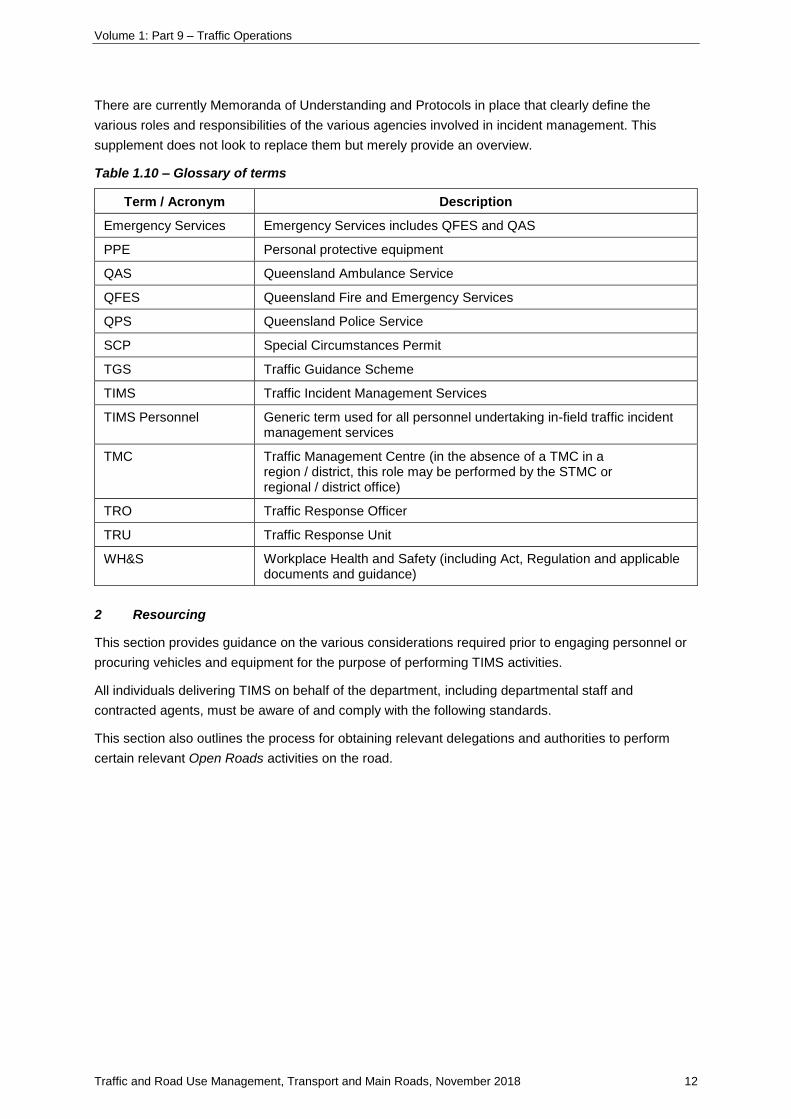
Table 1.10 – Glossary of terms
Term / Acronym Description
Emergency Services Emergency Services includes QFES and QAS
PPE Personal protective equipment
QAS Queensland Ambulance Service
QFES Queensland Fire and Emergency Services
QPS Queensland Police Service
SCP Special Circumstances Permit
TGS Traffic Guidance Scheme
TIMS Traffic Incident Management Services
TIMS Personnel Generic term used for all personnel undertaking in-field traffic incident management services
TMC Traffic Management Centre (in the absence of a TMC in a region / district, this role may be performed by the STMC or regional / district office)
TRO Traffic Response Officer
TRU Traffic Response Unit
WH&S Workplace Health and Safety (including Act, Regulation and applicable documents and guidance)
2 Resourcing
This section provides guidance on the various considerations required prior to engaging personnel or
procuring vehicles and equipment for the purpose of performing TIMS activities.
All individuals delivering TIMS on behalf of the department, including departmental staff and
contracted agents, must be aware of and comply with the following standards.
This section also outlines the process for obtaining relevant delegations and authorities to perform
certain relevant Open Roads activities on the road.

Volume 1: Part 9 – Traffic Operations
Traffic and Road Use Management, Transport and Main Roads, November 2018 13
2.1 Work health and safety
TIMS personnel, whether it be internal Transport and Main Roads (for example, RoadTek) or a
contracted agent, must comply with all requirements with respect to work health and safety (WH&S).
The TIMS personnel and agent must:
• abide by WH&S provisions as detailed in the Act and Regulation
• maintain appropriate WH&S standards and ensure a Quality and Safety System, compliant
with the department's legal requirements, is implemented
• hold current certification to Quality Management System AS/NZS ISO 9001:2016 and
Occupational Health and Safety Management System AS/NZS 4801:2001 (or an equivalent
standard)
• develop and supply appropriate Safe Work Method Statements prior to the operation of the
service that aligns and conforms to legislation and WH&S practices
• work towards a zero-harm policy
• report any injuries, illness or dangerous occurrence (including near-misses) in accordance
with the reporting requirements of WH&S – these incidents should also to be reported to
Transport and Main Roads if TIMS is delivered by contract
• inform itself, and keep its employees informed, of the requirements of all laws and ensure the
TIMS provider and its employees comply with those laws and requirements
• ensure the conduct of their employees comply with the TIMS providers’ obligations, including
in relation to conduct
• ensure all personnel have and use the required personal protective equipment (PPE) whilst
performing the Service.
The legislation can be found at:
https://www.legislation.qld.gov.au/view/html/inforce/current/act-2011-018.
2.2 Personnel standards
For the safety or themselves and others, TIMS personnel acting on behalf of, and at the direction of
the department, must:
• be competent, and appropriately trained, qualified and licensed to perform duties
• be in a satisfactory physical, mental and emotional state to perform duties competently
• be polite and courteous at all times when interacting with other road users as part of their
duties
• comply with all relevant legislation, policy, standard and guidelines in relation to their actions
and activities undertaken
• comply with any specific conditions of any approval attached to their licence or training
• comply with the employer’s Code of Conduct
• comply with all WH&S requirements
Volume 1: Part 9 – Traffic Operations
Traffic and Road Use Management, Transport and Main Roads, November 2018 14
• carry out lawful requests promptly, consistently and effectively when issued by a Police officer
or other authorised person
• maintain a ‘zero percent’ blood / alcohol concentration and be drug-free while on duty
• continually assess the safety of themselves and the activities being undertaken and act
responsibly
• wear PPE and uniform (as required) appropriate for the activities being undertaken
• report any unsafe activity, incident and near-miss
• adhere to all road rules, including those relating to travel, parking and pedestrian activities,
unless otherwise directed by an officer of the Queensland Police Service (QPS) or Emergency
Services or issued with a Special Circumstances Permit (SCP)
• keep proper and accurate records
• not exceed their authority or delegation
• be accountable for their actions.
For the safety or themselves and others, TIMS personnel acting on behalf of, and at the direction of
the department, must not:
• perform duties while affected by a drug or affected by medication causing impairment
• perform duties while fatigued
• carry out any action that could be deemed unsafe
• attempt to resolve disputes – if appropriate, calm the situation or move away and seek Police
assistance (if required)
• allow private, commercial or other employment interests to interfere with, or influence, their
actions
• directly or indirectly request or accept gifts, commissions or benefits of any kind from any
member of the public, media or towing company
• towing company spotter's fees in particular are expressly forbidden and all offers made to
TIMS personnel must be declined and reported to the TMC.
Should any issue, incident or near-miss arise from these points, it must be reported to the TMC as
soon as practical. This does not replace any other reporting requirements.
2.2.1 Breach of regulation, this supplement or procedures
If a report of a possible breach of regulations, this supplement or procedures by TIMS personnel is
received, an authorised person nominated by the region will be responsible for assessing the situation
and taking appropriate action in accordance with Transport and Main Roads policy, guidelines, Code
of Conduct and Ethical Standards.
2.2.2 Damage liability
The Transport Operations (Road Use Management) Act 1995 s51N is designed to provide protection
from civil liability when powers to move or remove a vehicle from a road under s51G are exercised in a
reasonable way. It will not provide protection if actions are carried out negligently. Thus, s51N will not
protect against liability where a vehicle, load or other thing is damaged while it is being moved or
Volume 1: Part 9 – Traffic Operations
Traffic and Road Use Management, Transport and Main Roads, November 2018 15
removed and the damage arises because a person's conduct in moving or removing the vehicle is
careless or reckless, such that their actions amount to negligence.
2.3 Uniforms and personal protective equipment
While on duty, all personnel providing TIMS must wear uniforms and PPE appropriate for the functions
being undertaken and comply with the requirements of the:
• Workplace Health and Safety Act and Regulation
• Manual of Uniform Traffic Control Devices (MUTCD) Part 3 Works on Roads.
This equipment includes, but is not limited to, the wearing of long-sleeved shirts, long-legged
trousers (with reflective bands) and a broad brimmed hat.
To ensure consistency in the appearance of all personnel providing TIMS, Transport and Main Roads
employees providing TIMS must wear departmentally-approved uniforms and road safety protective
and reflective clothing, including wet-weather clothing. Uniforms shall display departmental branding
and position title, and designs must be in line with existing services.
In addition to the standard PPE requirements specified, contracted TIMS personnel acting on behalf of
the department should, at minimum, wear clothing such as a shirt or vest featuring departmental
branding and position title, which must be approved by the department.
2.4 Delegations and authorisations
Certain TIMS activities require authorities and/or delegations. The following outlines these activities
and related legislation provisions.
2.4.1 Open Roads legislation
Following is an overview of Open Roads powers and responsibilities in the legislation. For exact
wording, please see Part 4C of the Transport Operations (Road Use Management) Act 1995.
Section 51G provides the power to:
• move or remove the vehicle, load or other thing from the road, or
• request a service or towing operator to remove the vehicle, load or other thing.
Section 51M provides the power to:
• immediately dispose in particular circumstances.
Section 51I provides the power to:
• recover moving expenses from the last person in charge (or owner) of the removed thing.
Section 51L provides the power to:
• dispose of removed things if not claimed and moving expenses paid after two months.
Generally, TIMS personnel do not have these delegations. This is usually held by TMC personnel.
Volume 1: Part 9 – Traffic Operations
Traffic and Road Use Management, Transport and Main Roads, November 2018 16
2.4.2 Vehicle registration information
Under s119(1) of the Transport Operations (Road Use Management – Vehicle Registration)
Regulation 2010, authorised departmental staff can access registered vehicle operator details for the
purpose of making contact in relation to moving or removing vehicles (under s51G of the Transport
Operations (Road Use Management) Act 1995.
Generally, TIMS personnel do not have these delegations. This is usually held by TMC personnel.
2.4.3 Placing traffic control devices on roads
Generally, TIMS personnel do not have the delegation to install or remove official traffic signs. This is
usually held by TMC personnel. TIMS personnel act under the direction of the TMC.
TIMS personnel may place traffic control devices on a road if:
• directed by an appropriate delegate in the TMC to install or remove official traffic signs from a
road or off-street regulated area (as defined in s68 of the Transport Operations (Road Use
Management) Act 1995)
• directed by an appropriate delegate in the TMC to install official traffic signs in case of
danger (as defined in s71 of the Transport Operations (Road Use Management) Act 1995)
• directed by an appropriate delegate in the TMC, to erect or display a restricted road use notice
to prevent damage to road transport infrastructure or to ensure the safety of road users and
other persons (as defined in s46(1) of the Transport Infrastructure Act 1994)
• directed by Police, Queensland Fire and Rescue Service or Ambulance Services to implement
traffic control at an incident scene (as defined in the Fire and Emergency Services Act 1990
and the Ambulance Service Act 1991).
2.4.4 Effect a road closure
Generally, TIMS personnel do not officially close a road – they typically act under the direction of the
TMC or other authorised officer with legal delegations (Regional Director or regional engineer) to
close / open a road.
For situations that require traffic to be stopped or diverted due to a dangerous situation (for example,
crash or flood), appropriate signage can be deployed under s71 of the Transport Operations (Road
Use Management) Act 1995 which provides the power to install official traffic signs in case of danger.
This is often referred to as an informal road closure.
2.4.5 Traffic control
Section 96(5) of the Transport Operations (Road Use Management) Act 1995 provides the power to
temporarily prohibit, divert or direct traffic and take other related actions to ensure the safe and
effective regulation of traffic.
TIMS personnel that have this delegation (that is, they are an accredited Traffic Controller) can only
operate within the department's approved procedure for controlling traffic. Refer to the Traffic
Controller Accreditation Scheme Approved Procedure
https://www.tmr.qld.gov.au/business-industry/Accreditations/Traffic-Controller-Accreditation-
Scheme
for further details.

Volume 1: Part 9 – Traffic Operations
Traffic and Road Use Management, Transport and Main Roads, November 2018 17
TIMS personnel who are not an accredited Traffic Controller cannot place traffic control devices on
roads without first seeking approval from a delegated officer, including a Police officer.
2.4.6 Road rule exemptions and Special Circumstance Permit
TIMS personnel have no exemptions from road rules, unless in possession of a Special
Circumstances Permit (SCP) and acting under the conditions of that permit.
Officers providing certain types of incident response services may apply for a SCP under s128 of the
Transport Operations (Road Use Management – Accreditation and Other Provisions) Regulation 2015
which grants exemptions to certain provisions of the Transport Operations (Road Use Management –
Road Rules) Regulation 2009.
For information on SCPs, email:
2.4.7 Emergency personnel status
Departmental vehicles providing incident response services do not have emergency vehicle and
worker status (that is, they cannot operate under red and blue flashing lights and a siren as an
ambulance or Police car can). TIMS personnel respond to traffic incidents under normal road use
conditions and must comply with all road rules, unless otherwise exempted and if necessary to do so,
while attending, or performing duty associated with, a traffic incident on a road.
2.5 Vehicle and equipment requirements
All TIMS vehicles must be suited and equipped to safely undertake the activities they are intended for.
Consideration needs to be made, but not limited to:
• safely undertake the tasks that will be required to be performed, especially access to
equipment in high-speed environment
• meet the requirements of the tasks that they will be required to perform; and
• present a consistent image of the department.
All vehicles, plant and equipment must be serviced and maintained in accordance with the relevant
Australian Standards and/or manufacturer’s specifications to fulfil the requirements of the provider.
Accurate maintenance and service records must be maintained and provided upon request for all
items of plant and equipment to be used.
All equipment must comply with the MUTCD and any other legal requirements.
Personnel providing TIMS must be adequately trained on all supplied equipment and possess the
required certifications of licences.

Volume 1: Part 9 – Traffic Operations
Traffic and Road Use Management, Transport and Main Roads, November 2018 18
2.5.1 Vehicle modification
For vehicle modifications, refer to the departmental website for details:
• Light vehicles (up to 4.5t GVM)
https://www.tmr.qld.gov.au/Safety/Vehicle-standards-and-modifications/Vehicle-
modifications/Light-vehicle-modifications
• Heavy vehicles (over 4.5t GVM)
https://www.tmr.qld.gov.au/Safety/Vehicle-standards-and-modifications/Vehicle-
modifications/Heavy-vehicle-modifications
This would include any requirements to attach non-standard equipment such as padded front bumper
for push / shunt disabled vehicles.
2.5.2 Livery and branding
All dedicated and specifically-equipped vehicles for TIMS purposes should use the half-Battenberg
livery and be clearly and easily identifiable as a Transport and Main Roads vehicle. This includes
vehicles used for other purposes, but that are primarily used for incident response duties. The
intention of this livery is to maximise visibility and safety on the road.
The livery should also be consistent with existing TIMS already in operation within the department.
Branding should include:
• blue and yellow (Battenberg) chequerboard pattern on front and side of vehicle (as illustrated
in Figure 2.5.2(A)
• red and yellow chevrons on back of vehicle (as illustrated in Figure 2.5.2(B)
• vehicle service type (for example, ‘Traffic Response Unit’) clearly printed on the vehicle
• Queensland Government logo
• QLDTraffic website and 13 19 40 phone details.
Figure 2.5.2(A) – Blue and yellow (Battenberg) chequerboard pattern on front and side of
vehicle
Figure 2.5.2(B) – Red and yellow chevrons on back of vehicle
Regions that use standard departmental vehicles for providing TIMS in the absence of dedicated
incident response vehicles should ensure that vehicles are branded and equipped adequately to
operate safely within local network conditions.
If a contracted vehicle is used exclusively for the department, any variation to vehicle branding as
outlined here must be endorsed by the department.
Volume 1: Part 9 – Traffic Operations
Traffic and Road Use Management, Transport and Main Roads, November 2018 19
If a contracted vehicle is used for other business outside of contractual arrangements with the
department, it is understood that the vehicle may remain in the colours / decals of the service provider,
provided that, during contractual hours and acting under direction of the department, a Queensland
Government logo is affixed (generally with magnetic decals).
These logos must be removed while performing non-departmental business.
2.5.3 Rotating lights
TIMS vehicles are classed as a special use vehicle as per s99(6) of the Transport Operations (Road
Use Management – Vehicle Standards and Safety) Regulation 2010, As a special use vehicle,
s99(1)(b) states ‘a special use vehicle may be fitted with one or more flashing yellow lights’.
This is reinforced in the MUTCD.
TIMS personnel acting under the exemptions of a SCP while in operational mode and proceeding to,
or at, a scene of an incident, are required to travel in a vehicle with yellow flashing lights activated.
Any vehicle that may be controlled by an officer under these circumstances must be equipped with
yellow flashing lights.
Other coloured lights are not permitted, unless classed as an exempt vehicle. Exempt vehicles are
outlined in s99(1) of the Transport Operations (Road Use Management – Vehicle Standards and
Safety) Regulation 2010.
2.6 Established / defined services
2.6.1 Traffic Response Unit
The primary role of Traffic Response Officers (TRO) operating the Traffic Response Unit (TRU) is to:
• deploy traffic management (incident delineation and advance warning)
• undertake welfare checks
• contribute to the overall safe resolution and minimise traffic impacts of an incident.
This is achieved through a dedicated response to traffic management around an incident scene and
effective communication with the relevant TMC and other responding agencies.
2.6.1.1 Activities
A TRU generally performs the following activities:
• cooperate with Emergency Services and other agencies to minimise the duration and severity
of an incident and its effect on traffic flow by assisting with coordination of TIMS within the
TMC
• under the direction of the TMC, deploy other service providers (maintenance crews and towing
operators) as required to clear incident and/or provide additional traffic control resources
• attend incidents as required and make an initial assessment of the necessary incident
response required
• contribute to the overall safety of all responders
• patrol designated routes
• assist the TMC in providing incident management information to road users and Emergency
Services
Volume 1: Part 9 – Traffic Operations
Traffic and Road Use Management, Transport and Main Roads, November 2018 20
• under the direction of the TMC, execute traffic control arrangements to assist in reducing
traffic delays and keeping congestion to a minimum, including providing effective and safe
diversions around incidents
• provide a delineated incident precinct with traffic control devices that pre-warn and give
emergency direction to approaching traffic for a safe, controlled and efficient passage through
the incident precinct to protect responders and the public
• reduce consequential delays by using traffic management techniques to re-open lanes earlier
than would otherwise be possible
• respond to minor environmental spills
• undertake preventative and/or emergency road maintenance activities, including the removal
of obstructions, debris (where safe to do so – before it causes an incident) and other potential
hazards
• assist in the collection of information relevant to road agency investigation and recording of
traffic incidents, including the documentation of infrastructure damage, for cost recovery
purposes
• provide assistance to road users in high-risk or critical locations, as well as reducing potential
risk of secondary incidents, and
• pushing or shadowing / protecting in certain situations.
2.6.1.2 Out of scope
TROs are not authorised to provide the following services:
• carry out any action that could be deemed unsafe
• carry out mechanical repairs on vehicles
• provide medical help beyond basic first aid
• attempt to resolve disputes
• provide advice relating to legal rights or position
• give directives to motorists or in any way imply authority to do so
• drive a motorist's vehicle, unless identified as a role
• recommend a tow truck operator
• personally authorise the towing of a vehicle
• provide recovery technique advice
• offer any departmental resources for post-incident recovery of vehicles
• offer any assistance that is not authorised / delegated by the department to TIMS personnel.
When providing assistance to motorists, TIMS personnel should take care not to enable a vehicle such
that it can proceed in unsatisfactory road conditions. An example would be fitting a bald tyre to a car.
It is also inappropriate for TIMS personnel to lend tools / equipment to motorists to enable them to
carry out their own repairs.
Volume 1: Part 9 – Traffic Operations
Traffic and Road Use Management, Transport and Main Roads, November 2018 21
2.6.1.3 Authority to act
TRUs are able to operate semi-autonomously and independently for minor incidents, under direction
of a TMC to execute broader traffic management response to incidents and also under direction of
QPS.
The TRU should only respond to an incident when called out, or agreed to, by the TMC. Under no
circumstance should they respond to an incident when they have been contacted directly by QPS
and/or Emergency Services. This also includes diverted landline calls from the TMC. In the event the
TRU is called out directly by QPS and/or Emergency Services, the TIMS personnel are to advise them
to contact the TMC and wait for the TMC to contact them. TIMS personnel are to log the call on their
daily duty sheet or record.
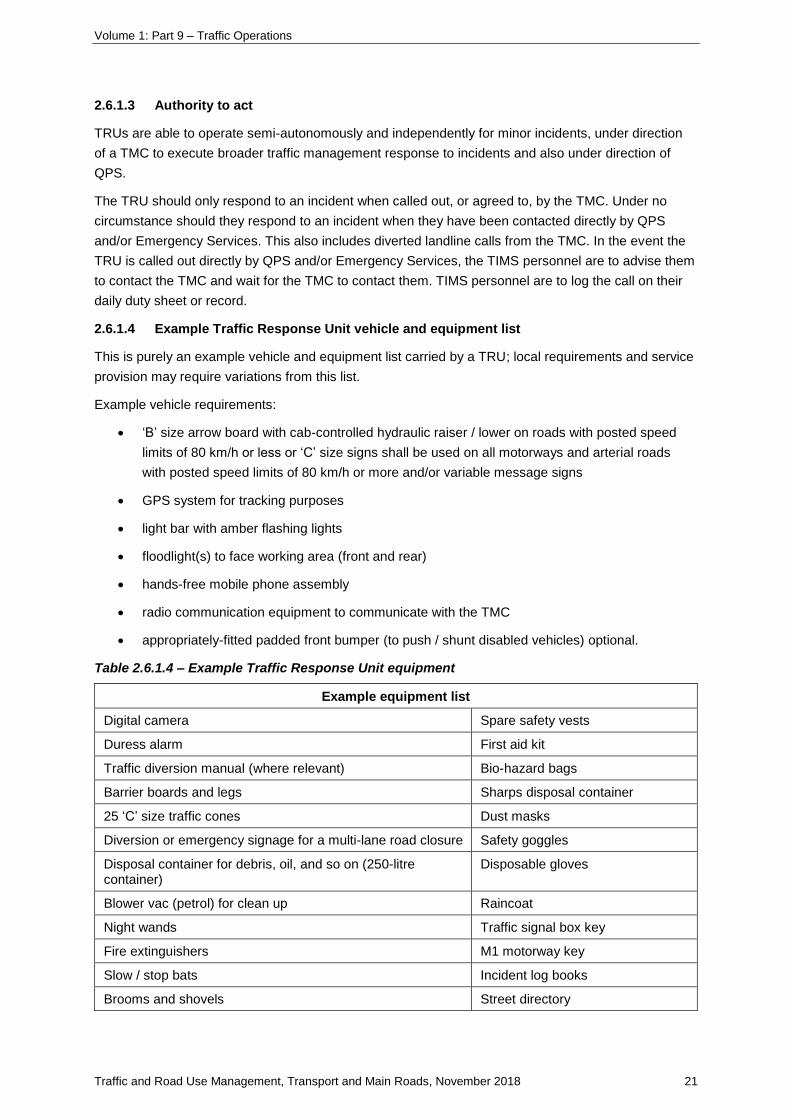
2.6.1.4 Example Traffic Response Unit vehicle and equipment list
This is purely an example vehicle and equipment list carried by a TRU; local requirements and service
provision may require variations from this list.
Example vehicle requirements:
• ‘B’ size arrow board with cab-controlled hydraulic raiser / lower on roads with posted speed
limits of 80 km/h or less or ‘C’ size signs shall be used on all motorways and arterial roads
with posted speed limits of 80 km/h or more and/or variable message signs
• GPS system for tracking purposes
• light bar with amber flashing lights
• floodlight(s) to face working area (front and rear)
• hands-free mobile phone assembly
• radio communication equipment to communicate with the TMC
• appropriately-fitted padded front bumper (to push / shunt disabled vehicles) optional.
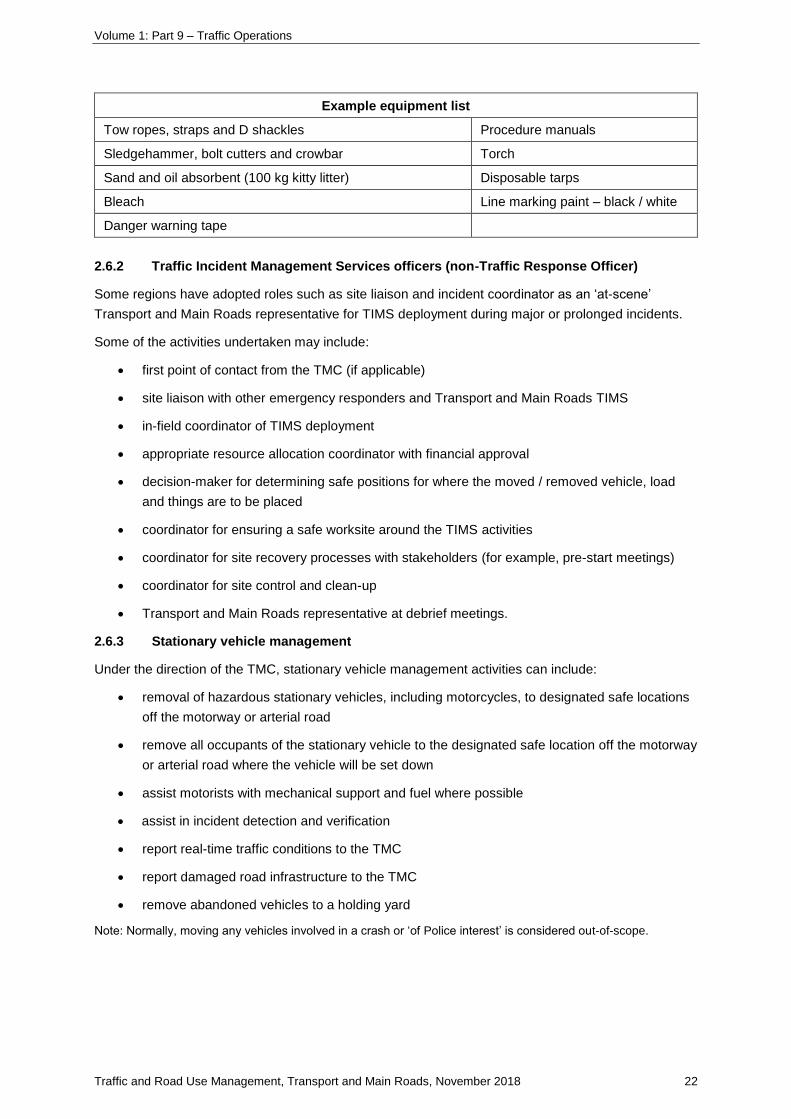
Table 2.6.1.4 – Example Traffic Response Unit equipment
Example equipment list
Digital camera Spare safety vests
Duress alarm First aid kit
Traffic diversion manual (where relevant) Bio-hazard bags
Barrier boards and legs Sharps disposal container
25 ‘C’ size traffic cones Dust masks
Diversion or emergency signage for a multi-lane road closure Safety goggles
Disposal container for debris, oil, and so on (250-litre container)
Disposable gloves
Blower vac (petrol) for clean up Raincoat
Night wands Traffic signal box key
Fire extinguishers M1 motorway key
Slow / stop bats Incident log books
Brooms and shovels Street directory
Volume 1: Part 9 – Traffic Operations
Traffic and Road Use Management, Transport and Main Roads, November 2018 22
Example equipment list
Tow ropes, straps and D shackles Procedure manuals
Sledgehammer, bolt cutters and crowbar Torch
Sand and oil absorbent (100 kg kitty litter) Disposable tarps
Bleach Line marking paint – black / white
Danger warning tape
2.6.2 Traffic Incident Management Services officers (non-Traffic Response Officer)
Some regions have adopted roles such as site liaison and incident coordinator as an ‘at-scene’
Transport and Main Roads representative for TIMS deployment during major or prolonged incidents.
Some of the activities undertaken may include:
• first point of contact from the TMC (if applicable)
• site liaison with other emergency responders and Transport and Main Roads TIMS
• in-field coordinator of TIMS deployment
• appropriate resource allocation coordinator with financial approval
• decision-maker for determining safe positions for where the moved / removed vehicle, load
and things are to be placed
• coordinator for ensuring a safe worksite around the TIMS activities
• coordinator for site recovery processes with stakeholders (for example, pre-start meetings)
• coordinator for site control and clean-up
• Transport and Main Roads representative at debrief meetings.
2.6.3 Stationary vehicle management
Under the direction of the TMC, stationary vehicle management activities can include:
• removal of hazardous stationary vehicles, including motorcycles, to designated safe locations
off the motorway or arterial road
• remove all occupants of the stationary vehicle to the designated safe location off the motorway
or arterial road where the vehicle will be set down
• assist motorists with mechanical support and fuel where possible
• assist in incident detection and verification
• report real-time traffic conditions to the TMC
• report damaged road infrastructure to the TMC
• remove abandoned vehicles to a holding yard
Note: Normally, moving any vehicles involved in a crash or ‘of Police interest’ is considered out-of-scope.
Volume 1: Part 9 – Traffic Operations
Traffic and Road Use Management, Transport and Main Roads, November 2018 23
2.7 Qualifications, training and progression
2.7.1 General
TIMS contribute to the overall desired outcomes of the Open Roads policy by facilitating effective
traffic management around an incident scene, including rapid response and clearance of traffic
incidents, contributing to the overall safety of all responders, and reducing the potential or risk of
secondary incidents.
Such activities can result in exposure to a range of hazardous or sensitive situations, including:
• working on or near roads with varying traffic conditions
• personal danger from vehicles approaching or passing an incident scene
• trauma resulting from attendance at serious injury and fatality scenes
• dealing with distressed and sometimes temporarily irrational persons at an incident scene
• formal complaints from the public concerning responder actions at an incident scene.
To ensure that TIMS personnel are fully equipped to manage or avoid hazardous situations, training
and progression programs should be undertaken to facilitate safe, effective operations.
Each region is responsible for ensuring that officers performing TIMS are adequately trained to
undertake the tasks required of them in a safe manner. TIMS personnel should aim to meet a similar
level of training and qualifications as outlined in this supplement.
2.7.2 Training, certification and competency checks
Personnel employed to provide TIMS are required to be competent, adequately trained and have the
appropriate licences, accreditation and certification to perform their role safety and effectively. It is the
responsibility of supervisors and employers to ensure that systems are in place for this to occur.
It is a requirement that all licences, accreditations and certification are current and adequate refresher
training is provided to ensure competency is maintained.
Records of all training, licensing and accreditation should be maintained and be able to be made
available upon request for auditing purposes. Should training and/or accreditation be incomplete, a
‘show cause’ may be requested and action taken as appropriate.
It is not necessarily possible or required for competency to be formally assessed prior to employment;
however, it is expected that competencies would be confirmed as soon as practical. If a new employee
is unable to demonstrate the required competencies within a reasonable period, their continued
employment should be reviewed.
At times, formal training may not be required due to previous experience and roles. Recognition of
prior learning may be considered on a case-by-case basis and competence assessed by a certified
workplace assessor.
To ensure TIMS personnel are competent and appropriately trained in the required skills to perform
their role, a learning log needs to be developed and maintained for each officer. The holding of a
qualification, certificate or licence does not necessarily reflect the competency of the officer. The
learning log provides an opportunity for the supervisor to confirm for themselves the competency of
the officer and/or identify training needs. Local WH&S and/or training representatives should be able
to provide guidance on developing these documents.

Volume 1: Part 9 – Traffic Operations
Traffic and Road Use Management, Transport and Main Roads, November 2018 24
2.7.3 Trauma management and counselling
The attendance of incidents that involve serious injury and fatality can be distressing and traumatic;
this can result in longer-term health issues for employees. Access to counselling services is
recommended.
The availability of these services should be advised prior to commencing this role and included in the
induction process. It is expected that supervisors and employers should offer counselling services,
and employees will attend counselling whenever they are exposed to distressing and traumatic
incidents.
The Employee Assistance Scheme is available to support Transport and Main Roads employees and
their families; supervisors or the department’s human resources personnel can assist accessing these
services.
All other TIMS providers will have their own counselling services in place as part of their contract.
2.7.4 Training and qualification framework for Traffic Response Officers
Due to the nature of the role, a progression framework has been developed to manage the training
and qualification requirements of a TRO from initial engagement to fully qualified. This guidance
should be tailored to the specifics of the role being undertaken and the operating environment as well
as WH&S obligations.
TROs progress through various levels as they undertake training and gain the relevant experience and
qualifications. The table following outlines the suggested operational restrictions, dependant on status
level.
Table 2.7.4 – Status level relationship to operational restrictions
Status level Operational restrictions
Pre-on road TRO No on-road activities
Trainee TRO Restrictions on activities apply
Trainee TRO to be accompanied by a qualified TRO
Probationary TRO Can operate independently but with restrictions
Fully-qualified TRO Can operate independently
Progression through each status is subject to assessment and approval. The ‘approving officer’ will
typically be:
• the immediate supervisor of the TRO
• the appropriate team leader or other senior position holder, and/or
• a certified workplace assessor.
The following approach has been developed to assist progression through each stage and achieve
fully-qualified TRO status. A learning log (shown in Table 2.7.4.4) is the simplest form to document
progress.

Volume 1: Part 9 – Traffic Operations
Traffic and Road Use Management, Transport and Main Roads, November 2018 25
2.7.4.1 Pre-on road Traffic Response Officer
Prior to commencing on road activities with a qualified TRO, the suggested minimum training and
evidence required as a trainee TRO (shown in Table 2.7.4.5) is sighted by the approving officer.
These requirements may need to change to meet local conditions.
2.7.4.2 Trainee Traffic Response Officer
A TRO will have 'trainee' status from initial appointment to the role until sufficient training and
assessment has been undertaken and the approving officer has assessed that the TRO has satisfied
all requirements to progress to ‘probationary’ status.
A trainee TRO can only operate 'on road' when accompanied by a qualified TRO.
When attending an incident scene in the company of a qualified TRO, a trainee TRO shall:
• not undertake any activity unless specifically instructed to by the qualified TRO
• not volunteer assistance to Emergency Services personnel or in any way impede their
activities or the activities of other responders
• not speak to any member of the public, including media representatives or if directly
approached, or make any comment regarding the incident or any other aspect of Transport
and Main Roads and Emergency Services activities
• carry identification as a trainee, such as a ‘trainee badge’.
In addition to the training and assessment (suggested as shown in Table 2.7.4.5), it is recommended
that the following are completed to the satisfaction the approving officer:
• attendance at incident scenes as an assistance to a qualified TRO (minimum 14 days or
30 incidents)
• exposure to a sufficient range of incident types to have gained sufficient experience in opinion
of the qualified accompanying TRO.
These requirements may need to change to meet local conditions.
2.7.4.3 Probationary Traffic Response Officer
A TRO at this level will undergo a probationary period of assessment during which he or she can
operate independently but with restrictions placed on the incident response activities that may be
undertaken.
A TRO will have the status of probationary TRO from successful completion of the trainee TRO
requirements until sufficient training and assessment has been undertaken and the approving officer
has assessed that the TRO has satisfied all requirements to progress to qualified TRO status.

Volume 1: Part 9 – Traffic Operations
Traffic and Road Use Management, Transport and Main Roads, November 2018 26
Successful completion of probationary TRO requirements is subject to assessment by the approving
officer, and will be based on:
• completion of all TRO training and learning to the satisfaction of the approving officer (both
self-assessment and manager approval)
• demonstrated knowledge of incident response procedures, methods and documents
• attendance at a sufficient number of incidents to have encountered all common situations and
assessment of incident scene performance, and
• attainment and/or maintenance of required qualifications.
A probationary TRO can operate alone but may be restricted in his or her assignment of activities.
These restrictions should be issued in writing and explained to the probationary TRO. Restrictions are
dependent on a case-by-case basis and are based on the level of the individuals' level of competency
as determined by the approving officer.
Self-assessment should be recorded in the probationary TRO’s training log and reviewed by the
approving officer. The approving officer determines the total length of probation.
Although restrictions are determined by the approving officer, probationary TROs are generally
restricted during this period and can only operate on a motorway under the following conditions:
1. Upon arrival at an incident, the probationary TRO will introduce himself or herself to
Emergency Services officers and offer assistance.
2. Lane closures / traffic control can only be done under the direction of Police and the
probationary TRO can only continue these operations while Police are on the scene.
3. Assistance to motorists can only be provided to those on the left shoulder of the motorway, not
beside the median strip.
4. In a right-hand lane incident, the TRO can provide protective positioning of the vehicle only
until Police arrival when the TRO will then operate as indicated at items 1 and 2 of these
conditions.
Restrictions may be progressively withdrawn, depending on the experience of the probationary TRO
and endorsement by the approving officer.
Probationary TROs shall contact the TMC, or in the absence of a TMC, another appropriate appointed
officer, when:
• it is necessary to close a lane in a high-speed traffic environment in accordance with items 1,
2 or 3 listed previously
• the QPS Forensic Crash Unit is attending an incident, typically for fatalities
• unusual or costly equipment and services are required as resource upgrades
• probationary TROs shall only organise resource upgrades through the TMC
• there is an incident or situation where Transport and Main Roads Corporate should be advised
of the circumstances – TRO would contact the TMC who will deal with the call in line with
policy
• there is any case of dispute involving the TRO at the scene of the incident.
Volume 1: Part 9 – Traffic Operations
Traffic and Road Use Management, Transport and Main Roads, November 2018 27
Probationary TROs shall not perform first aid unless they hold a Senior First Aid Certificate.
Probationary TROs are encouraged to seek qualified advice via the TMC and/or Police on scene if
there are concerns about the TRO’s personal ability / training to manage a particular incident.
Personal safety and welfare is most important.
These requirements may need to change to meet local conditions.
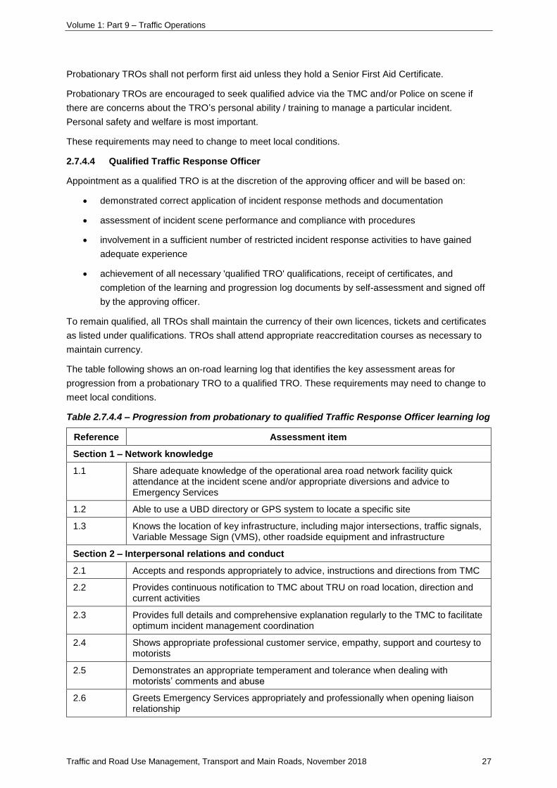
2.7.4.4 Qualified Traffic Response Officer
Appointment as a qualified TRO is at the discretion of the approving officer and will be based on:
• demonstrated correct application of incident response methods and documentation
• assessment of incident scene performance and compliance with procedures
• involvement in a sufficient number of restricted incident response activities to have gained
adequate experience
• achievement of all necessary 'qualified TRO' qualifications, receipt of certificates, and
completion of the learning and progression log documents by self-assessment and signed off
by the approving officer.
To remain qualified, all TROs shall maintain the currency of their own licences, tickets and certificates
as listed under qualifications. TROs shall attend appropriate reaccreditation courses as necessary to
maintain currency.
The table following shows an on-road learning log that identifies the key assessment areas for
progression from a probationary TRO to a qualified TRO. These requirements may need to change to
meet local conditions.
Table 2.7.4.4 – Progression from probationary to qualified Traffic Response Officer learning log
Reference Assessment item
Section 1 – Network knowledge
1.1 Share adequate knowledge of the operational area road network facility quick attendance at the incident scene and/or appropriate diversions and advice to Emergency Services
1.2 Able to use a UBD directory or GPS system to locate a specific site
1.3 Knows the location of key infrastructure, including major intersections, traffic signals, Variable Message Sign (VMS), other roadside equipment and infrastructure
Section 2 – Interpersonal relations and conduct
2.1 Accepts and responds appropriately to advice, instructions and directions from TMC
2.2 Provides continuous notification to TMC about TRU on road location, direction and current activities
2.3 Provides full details and comprehensive explanation regularly to the TMC to facilitate optimum incident management coordination
2.4 Shows appropriate professional customer service, empathy, support and courtesy to motorists
2.5 Demonstrates an appropriate temperament and tolerance when dealing with motorists’ comments and abuse
2.6 Greets Emergency Services appropriately and professionally when opening liaison relationship

Volume 1: Part 9 – Traffic Operations
Traffic and Road Use Management, Transport and Main Roads, November 2018 28
Reference Assessment item
2.7 Understands and accepts Emergency Services authority and responds to directions and requests appropriately
2.8 Proactively influences Emergency Services and provides traffic management advice to reduce incident duration and severity
2.9 Recognises inner- and outer-cordon relationship between Police, TRU and TMC
2.10 Negotiates reasonable Transport and Main Roads outcomes with both Emergency Services and members of the public
2.11 Maintains member of public privacy and assists with appropriate shielding in the case of severe, injury, and death
Section 3 – Work practices and procedures
General
3.1 Understands and follows the ‘welfare check’ process operating between TMC and TRO
3.2 Can define legitimate incident types that the TRU should respond to
3.3 Follows operational procedure and safe work practices to maintain and enhance safety of responders, accident victims and self when providing assistance to Emergency Services, motoring public and accident victims
3.4 Demonstrates knowledge of the provisions of the Special Circumstances Permit
3.5 Able to conduct a tow or push competently using TRU vehicle, tow bar and push facilities
3.6 Able to conduct basic tasks, such as oil, water and other type checks, or assistance with a wheel change to facilitate quick removal of vehicle
3.7 Uses a fire extinguisher in accordance with correct and safe operating procedure
3.8 Able to interpret and implement traffic management plans
3.9 Implements appropriate traffic management technique to minimise risk and incident duration and severity
3.10 Complies with provisions of Traffic Controller certification when assisting with traffic control activities
3.11 Follows safe lifting – manual handling processes when removing and replacing equipment in the TRU vehicle
3.12 Wears appropriate PPE for the incident, including high-visibility vest, appropriate footwear and eye protection
3.13 Follows and applies the ‘Tow to Safety’ policy
3.14 Does not exceed authority or breach safety rules and regulations
3.15 Responds appropriately to a crime crash scene in order to preserve evidence
Site set-up / clearance
3.16 Can define the correct location for a TRU vehicle in specified incident types to reduce risk, incident severity and duration
3.17 Locates TRU vehicle at an incident to minimise risk and/or in accordance with specific scenario drawings and procedures and/or Emergency Services directions
3.18 Correctly positions traffic cones in accordance with high-speed road (M1) and other traffic management
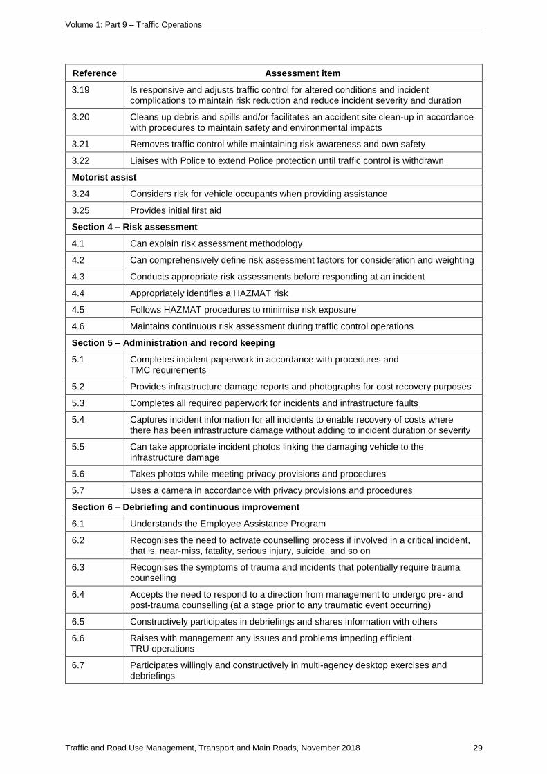
Volume 1: Part 9 – Traffic Operations
Traffic and Road Use Management, Transport and Main Roads, November 2018 29
Reference Assessment item
3.19 Is responsive and adjusts traffic control for altered conditions and incident complications to maintain risk reduction and reduce incident severity and duration
3.20 Cleans up debris and spills and/or facilitates an accident site clean-up in accordance with procedures to maintain safety and environmental impacts
3.21 Removes traffic control while maintaining risk awareness and own safety
3.22 Liaises with Police to extend Police protection until traffic control is withdrawn
Motorist assist
3.24 Considers risk for vehicle occupants when providing assistance
3.25 Provides initial first aid
Section 4 – Risk assessment
4.1 Can explain risk assessment methodology
4.2 Can comprehensively define risk assessment factors for consideration and weighting
4.3 Conducts appropriate risk assessments before responding at an incident
4.4 Appropriately identifies a HAZMAT risk
4.5 Follows HAZMAT procedures to minimise risk exposure
4.6 Maintains continuous risk assessment during traffic control operations
Section 5 – Administration and record keeping
5.1 Completes incident paperwork in accordance with procedures and TMC requirements
5.2 Provides infrastructure damage reports and photographs for cost recovery purposes
5.3 Completes all required paperwork for incidents and infrastructure faults
5.4 Captures incident information for all incidents to enable recovery of costs where there has been infrastructure damage without adding to incident duration or severity
5.5 Can take appropriate incident photos linking the damaging vehicle to the infrastructure damage
5.6 Takes photos while meeting privacy provisions and procedures
5.7 Uses a camera in accordance with privacy provisions and procedures
Section 6 – Debriefing and continuous improvement
6.1 Understands the Employee Assistance Program
6.2 Recognises the need to activate counselling process if involved in a critical incident, that is, near-miss, fatality, serious injury, suicide, and so on
6.3 Recognises the symptoms of trauma and incidents that potentially require trauma counselling
6.4 Accepts the need to respond to a direction from management to undergo pre- and post-trauma counselling (at a stage prior to any traumatic event occurring)
6.5 Constructively participates in debriefings and shares information with others
6.6 Raises with management any issues and problems impeding efficient TRU operations
6.7 Participates willingly and constructively in multi-agency desktop exercises and debriefings
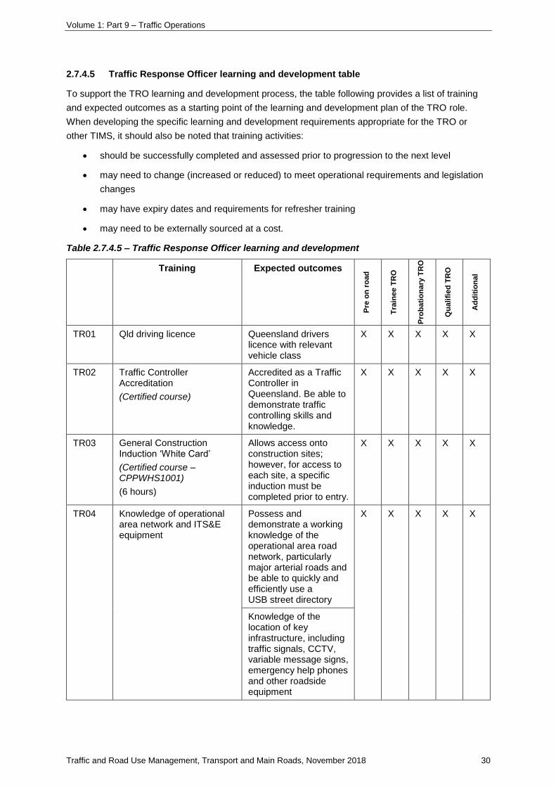
Volume 1: Part 9 – Traffic Operations
Traffic and Road Use Management, Transport and Main Roads, November 2018 30
2.7.4.5 Traffic Response Officer learning and development table
To support the TRO learning and development process, the table following provides a list of training
and expected outcomes as a starting point of the learning and development plan of the TRO role.
When developing the specific learning and development requirements appropriate for the TRO or
other TIMS, it should also be noted that training activities:
• should be successfully completed and assessed prior to progression to the next level
• may need to change (increased or reduced) to meet operational requirements and legislation
changes
• may have expiry dates and requirements for refresher training
• may need to be externally sourced at a cost.
Table 2.7.4.5 – Traffic Response Officer learning and development
Training Expected outcomes
Pre
on
ro
ad
Tra
ine
e T
RO
Pro
ba
tio
na
ry T
RO
Qu
ali
fied
TR
O
Ad
dit
ion
al
TR01 Qld driving licence Queensland drivers licence with relevant vehicle class
X X X X X
TR02 Traffic Controller Accreditation
(Certified course)
Accredited as a Traffic Controller in Queensland. Be able to demonstrate traffic controlling skills and knowledge.
X X X X X
TR03 General Construction Induction ‘White Card’
(Certified course – CPPWHS1001)
(6 hours)
Allows access onto construction sites; however, for access to each site, a specific induction must be completed prior to entry.
X X X X X
TR04 Knowledge of operational area network and ITS&E equipment
Possess and demonstrate a working knowledge of the operational area road network, particularly major arterial roads and be able to quickly and efficiently use a USB street directory
X X X X X
Knowledge of the location of key infrastructure, including traffic signals, CCTV, variable message signs, emergency help phones and other roadside equipment
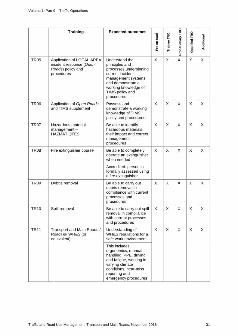
Volume 1: Part 9 – Traffic Operations
Traffic and Road Use Management, Transport and Main Roads, November 2018 31
Training Expected outcomes
Pre
on
ro
ad
Tra
ine
e T
RO
Pro
ba
tio
na
ry T
RO
Qu
ali
fied
TR
O
Ad
dit
ion
al
TR05 Application of LOCAL AREA incident response (Open Roads) policy and procedures
Understand the principles and processes underpinning current incident management systems and demonstrate a working knowledge of TIMS policy and procedures
X X X X X
TR06 Application of Open Roads and TIMS supplement
Possess and demonstrate a working knowledge of TIMS policy and procedures
X X X X X
TR07 Hazardous material management – HAZMAT QFES
Be able to identify hazardous materials, their impact and correct management procedures
X X X X X
TR08 Fire extinguisher course Be able to completely operate an extinguisher when needed
X X X X X
Accredited: person is formally assessed using a fire extinguisher
TR09 Debris removal Be able to carry out debris removal in compliance with current processes and procedures
X X X X X
TR10 Spill removal Be able to carry out spill removal in compliance with current processes and procedures
X X X X X
TR11 Transport and Main Roads / RoadTek WH&S (or equivalent)
Understanding of WH&S regulations for a safe work environment
X X X X X
This includes, ergonomics, manual handling, PPE, driving and fatigue, working in varying climate conditions, near-miss reporting and emergency procedures
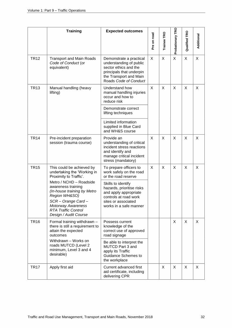
Volume 1: Part 9 – Traffic Operations
Traffic and Road Use Management, Transport and Main Roads, November 2018 32
Training Expected outcomes
Pre
on
ro
ad
Tra
ine
e T
RO
Pro
ba
tio
na
ry T
RO
Qu
ali
fied
TR
O
Ad
dit
ion
al
TR12 Transport and Main Roads Code of Conduct (or equivalent)
Demonstrate a practical understanding of public sector ethics and the principals that underpin the Transport and Main Roads Code of Conduct
X X X X X
TR13 Manual handling (heavy lifting)
Understand how manual handling injuries occur and how to reduce risk
X X X X X
Demonstrate correct lifting techniques
Limited information supplied in Blue Card and WH&S course
TR14 Pre-incident preparation session (trauma course)
Provide an understanding of critical incident stress reactions and identify and manage critical incident stress (mandatory)
X X X X X
TR15 This could be achieved by undertaking the ‘Working in Proximity to Traffic’.
Metro / NCHD – Roadside awareness training (In-house training by Metro Region WH&SO)
SCR – Orange Card – Motorway Awareness RTA Traffic Control Design / Audit Course
To prepare officers to work safely on the road or the road reserve
X X X X X
Skills to identify hazards, prioritise risks and apply appropriate controls at road work sites or associated works in a safe manner
TR16 Formal training withdrawn – there is still a requirement to attain the expected outcomes
Withdrawn – Works on roads MUTCD (Level 2 minimum, Level 3 and 4 desirable)
Possess current knowledge of the correct use of approved road signage
X X X
Be able to interpret the MUTCD Part 3 and apply its Traffic Guidance Schemes to the workplace
TR17 Apply first aid Current advanced first aid certificate, including delivering CPR
X X X X
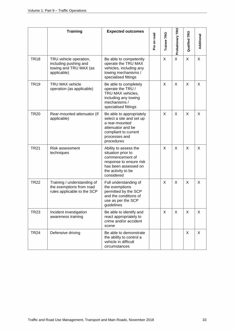
Volume 1: Part 9 – Traffic Operations
Traffic and Road Use Management, Transport and Main Roads, November 2018 33
Training Expected outcomes
Pre
on
ro
ad
Tra
ine
e T
RO
Pro
ba
tio
na
ry T
RO
Qu
ali
fied
TR
O
Ad
dit
ion
al
TR18 TRU vehicle operation, including pushing and towing and TRU MAX (as applicable)
Be able to competently operate the TRU MAX vehicles, including any towing mechanisms / specialised fittings
X X X X
TR19 TRU MAX vehicle operation (as applicable)
Be able to completely operate the TRU / TRU MAX vehicles, including any towing mechanisms / specialised fittings
X X X X
TR20 Rear-mounted attenuator (if applicable)
Be able to appropriately select a site and set up a rear-mounted attenuator and be compliant to current processes and procedures
X X X X
TR21 Risk assessment techniques
Ability to assess the situation prior to commencement of response to ensure risk has been assessed on the activity to be considered
X X X X
TR22 Training / understanding of the exemptions from road rules applicable to the SCP
Full understanding of the exemptions permitted by the SCP and the conditions of use as per the SCP guidelines
X X X X
TR23 Incident investigation awareness training
Be able to identify and react appropriately to crime and/or accident scene
X X X X
TR24 Defensive driving Be able to demonstrate the ability to control a vehicle in difficult circumstances
X X

Volume 1: Part 9 – Traffic Operations
Traffic and Road Use Management, Transport and Main Roads, November 2018 34
Training Expected outcomes
Pre
on
ro
ad
Tra
ine
e T
RO
Pro
ba
tio
na
ry T
RO
Qu
ali
fied
TR
O
Ad
dit
ion
al
TR25 TMC operations Understand TMC operations, policy and procedures in relations to TIMS (TMC Induction)
X X X X X
Observation of and instruction in the operation of the TMC (TMC induction)
TR26 TMC placement To observe / participate in TMC operations to gain knowledge of policy and procedures in relation to TIMS
X
TR27 TRO placement – operational or other area
Attendance at required number of incidents of period of time with a qualified TRO
X
TR28 Interpersonal skills (customer service)
Possess and demonstrate excellent interpersonal skills that contribute to successful and amicable communication with members of the public and officers of other agencies
X
TR29 Negotiation skills Possess and demonstrate negotiation skills that contribute to successful resolution of issues with member of the public and officers of other agencies
X
TR30 Traffic incident management plans
Be able to interpret and implement traffic incident management plans
X
TR31 Mechanical knowledge Possess and demonstrate a basic mechanical knowledge relevant to motor vehicles for the provision of emergency fuel, oil and water, and for assisting in tyre changing
X
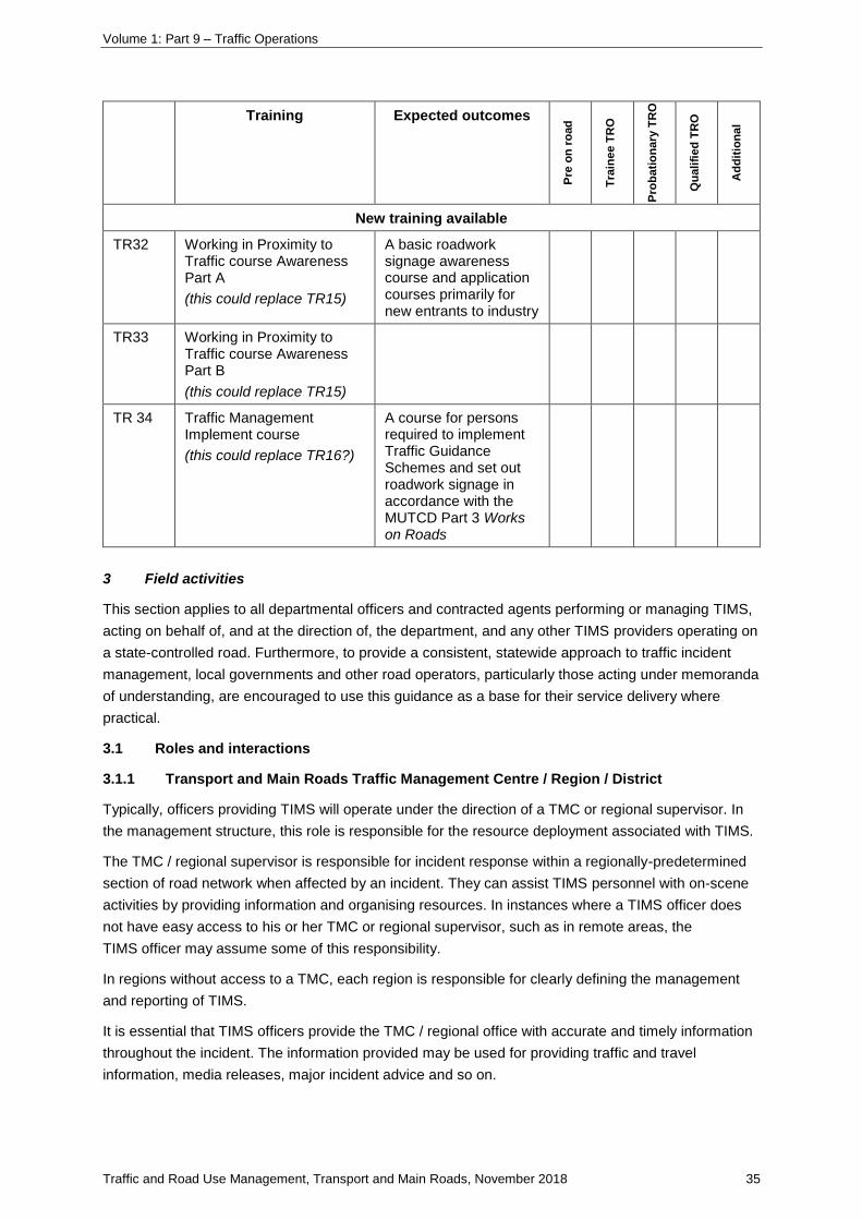
Volume 1: Part 9 – Traffic Operations
Traffic and Road Use Management, Transport and Main Roads, November 2018 35
Training Expected outcomes
Pre
on
ro
ad
Tra
ine
e T
RO
Pro
ba
tio
na
ry T
RO
Qu
ali
fied
TR
O
Ad
dit
ion
al
New training available
TR32 Working in Proximity to Traffic course Awareness Part A
(this could replace TR15)
A basic roadwork signage awareness course and application courses primarily for new entrants to industry
TR33 Working in Proximity to Traffic course Awareness Part B
(this could replace TR15)
TR 34 Traffic Management Implement course
(this could replace TR16?)
A course for persons required to implement Traffic Guidance Schemes and set out roadwork signage in accordance with the MUTCD Part 3 Works on Roads
3 Field activities
This section applies to all departmental officers and contracted agents performing or managing TIMS,
acting on behalf of, and at the direction of, the department, and any other TIMS providers operating on
a state-controlled road. Furthermore, to provide a consistent, statewide approach to traffic incident
management, local governments and other road operators, particularly those acting under memoranda
of understanding, are encouraged to use this guidance as a base for their service delivery where
practical.
3.1 Roles and interactions
3.1.1 Transport and Main Roads Traffic Management Centre / Region / District
Typically, officers providing TIMS will operate under the direction of a TMC or regional supervisor. In
the management structure, this role is responsible for the resource deployment associated with TIMS.
The TMC / regional supervisor is responsible for incident response within a regionally-predetermined
section of road network when affected by an incident. They can assist TIMS personnel with on-scene
activities by providing information and organising resources. In instances where a TIMS officer does
not have easy access to his or her TMC or regional supervisor, such as in remote areas, the
TIMS officer may assume some of this responsibility.
In regions without access to a TMC, each region is responsible for clearly defining the management
and reporting of TIMS.
It is essential that TIMS officers provide the TMC / regional office with accurate and timely information
throughout the incident. The information provided may be used for providing traffic and travel
information, media releases, major incident advice and so on.
Volume 1: Part 9 – Traffic Operations
Traffic and Road Use Management, Transport and Main Roads, November 2018 36
3.1.2 Police
QPS is responsible for public safety, law enforcement and crime scene preservation, and incident
investigation (of the inner cordon – the immediate incident scene at the time for which it is in effect).
When present at an incident scene, QPS is the primary responsible authority. It has specific powers
and delegations to direct the activities of any person at the scene, including departmental officers and
contracted agents undertaking TIMS.
In certain circumstances, alternative Emergency Services may temporarily assume authority to
manage certain aspects of the incident.
Under s59 Power for regulating vehicular and pedestrian traffic of the Police Powers and
Responsibilities Act 2000, Police Officers have wide-ranging powers to direct persons at any incident
scene to do or to not do anything the Officer believes to be necessary in the circumstances.
TIMS personnel must be aware that such directions have legal force.
Once Police arrive at an incident site, they should take command of the inner cordon of the incident
site and, as such, a TIMS officer who may already be onsite should provide a situation handover to
Police. At this point, the TIMS officer is under the direction of the Police and also assumes the role of
the Transport and Main Roads representative onsite.
A TIMS officer should never act against a direction issued from a Police Officer. If there is a safety
issue, the TIMS officer should discuss concerns with the Police Officer and seek an alternative
method / action, rather than simply refusing the direction. Should any specific concern for personal
safety remain, the issue should be escalated to the TMC / regional office for resolution as a matter of
urgency.
3.1.3 Emergency Services
Emergency Services, such as Queensland Fire and Emergency Service (QFES), Queensland
Ambulance Service (QAS) and the State Emergency Service, including volunteer fire and rescue
organisations, are responsible for rescuing injured people, treating and transporting the injured to
hospital and controlling fire and other site hazards. In the majority of incidents these responders
attend, they will operate under the guidance of the site commander (typically a Police Officer).
On occasions, because of the nature of the incident (such as a significant HAZMAT incident), a
QFES officer-in-charge may take control of the inner cordon. In such cases, an onsite TIMS officer
should remain under the direction of Police if also onsite.
When there is no Police presence at an incident, which may be the case in the early stages of an
incident, the TIMS officer is to work under the guidance of the QFES incident controller (if present).
This may require the TIMS officer explaining his or her resource capability and role as the Transport
and Main Roads representative onsite.
3.1.4 Media and general public
The Police generally give media access to the scene. TIMS personnel should allow identified media
representatives through road closures at incidents with agreement from Police. Any questions directed
to a TIMS officer should be redirected to the attending Police.

Volume 1: Part 9 – Traffic Operations
Traffic and Road Use Management, Transport and Main Roads, November 2018 37
When interacting with the media or members or the public, a TIMS officer:
• should not say ‘I am not allowed to make any comment’
• should be wary of media misquoting and, in particular, be careful to avoid making any
statements that may be overheard – conversations with the public should be limited and avoid
being overheard when liaising with the TMC, regional office or other responders
• shall not make any statement to the media concerning the incident, the progress of a
response or any other aspect of Transport and Main Roads business; requests for comment
should be responded to with:
- if a Police Officer is on the scene, ‘Sir / Madam, I am not the appropriate person to
speak to, however, you can talk to the attending Police or the Police Media Unit’
- if a Police Officer is not on the scene, ‘Sir / Madam, I am not the appropriate person to
speak to; however, you can talk to the Transport and Main Roads Communications
Unit’ and provide Transport and Main Roads Communications unit contact details
• shall contact the TMC coordinator / regional supervisor or other appointed officer if there is
any indication of official public complaint or where Transport and Main Roads is being
threatened with legal proceedings or adverse media reports as the result of an incident.
3.2 Communication protocols
Whenever using a communications device (such as telephone or radio), and in critical direct
conversation, speak clearly and slowly. Where possible, plan the message before speaking. Ensure
that the information is received correctly and, if in doubt, ask for read-back confirmation.
3.2.1 Confidentiality and discretion
TIMS personnel shall:
• as far as is possible, ensure that communications are not overheard by the public or media
• avoid incident commentary or discussion beyond direct responsibility for traffic management
issues.
Volume 1: Part 9 – Traffic Operations
Traffic and Road Use Management, Transport and Main Roads, November 2018 38
3.2.2 Phonetics
Table 3.2.2 – Phonetic alphabet, numbers and time of day
Alphabet
‘When in doubt, spell it out’.
Use the phonetic alphabet to spell out critical words, particularly vehicle number plates. Ensure the state the plate is registered in is recorded, including Queensland plates.
A – Alpha E – Echo I – India M – Mike Q – Quebec U – Uniform Y – Yankee
B – Bravo F – Foxtrot J – Juliet N – November R – Romeo V – Victor Z – Zulu
C – Charlie G – Golf K – Kilo O – Oscar S – Sierra W – Whisky
D – Delta H – Hotel L – Lima P – Papa T – Tango X – X-ray
Numbers
Numbers shall always be spoken as shown. Other numbers may be pronounced as normal in non-critical communications. Example: 309 = ‘Three hundred and niner’ = ‘Three Zero-Niner’.
0 – Zero (not ‘oh’, ‘nought’) 14 – One-four 17 – One-seven
9 – Niner 15 – One-five 18 – One-eight
13 – One-three 16 – One-six 19 – One-nine
Time of day
Always use the 24-hour clock to refer to time of day. Include an initial ‘Zero’ for times prior to 1000 hrs, example: 6:15 AM is 0615 hrs, pronounced ‘Zero Six One-Five Hours’.
Midnight is either 2359 hrs or 0001 hrs, never 0000 hrs.
3.3 Call-out and operational considerations
Following are the steps, considerations and check points of the generic call-out and operational
considerations for TIMS. Depending on the incident (or activity), some or all the information is required
when setting up contracts and work procedures.
3.3.1 Incident call-out
TMC operators and direct supervisors are the only persons normally authorised to call-out
TIMS personnel or direct them to a particular incident, unless the TIMS personnel are operating in
'autonomous' mode (such as while out of phone / radio contact).
In exceptional circumstances, TIMS personnel may respond directly to Police requests for attendance
but must immediately inform a TMC operator or regional supervisor that he or she has been so
directed.
TIMS personnel on duty may stop to attend incidents that are detected during routine travel but should
seek immediate approval from the TMC operator or regional supervisor to respond.
All requests for departmental TIMS attendance must be made through the TMC or regional supervisor
where possible in the first instance.

Volume 1: Part 9 – Traffic Operations
Traffic and Road Use Management, Transport and Main Roads, November 2018 39
The TMC should provide as many details as possible to the TIMS personnel prior to attending the
incident. These could include:
• incident location – road, suburb, nearest cross-street or other location identifier
• direction and affected lanes, changes to the road access
• description of incident and severity, number and type of vehicles
• if Police or Emergency Services are on route or at scene
• extent of injuries – particularly if a fatality is suspected (and Forensic Crash Unit is required).
3.3.2 Travelling to incident scene
While travelling / proceeding to the scene of the incident, the following must be adhered to:
• obey all traffic signals, signage and road markings
• activate SCP conditions if issued and appropriate
• plan approach route, allowing for location and traffic conditions
• TMC advice on best approach to the incident scene
• TMC supervisor to provide traffic and incident information using CCTV
• confirm estimated time of arrival to TMC.
These duties must be performed safely and with minimal interference to other road users.
3.3.3 Arrival at incident scene
3.3.3.1 Positioning of Traffic Incident Management Services vehicles at incident scene
Vehicles must be positioned safely and at a distance to allow a safe exit and entry for individuals and
to avoid obstruction to traffic (unless intended) or other responders. The positioning of vehicles must
consider:
• access and parking of Emergency Service vehicles and other response vehicles arriving and
leaving the scene
• distance allowance for ‘vehicle break-through’ of the traffic cones in the event of emergency
braking by an approaching vehicle.
3.3.3.2 Use of Traffic Incident Management Services vehicle equipment
If using vehicles fitted with a variable message sign and/or arrow board, an appropriate message and
arrow should be displayed.
Use of the variable message sign should be in accordance with the Traffic and Road Use
Management manual Volume 1 Part 10 Traffic Control and Communications Devices and the
Queensland MUTCD.
If other equipment, such as emergency signage (including roll-out signage) is available, it should be
placed in accordance with the Queensland MUTCD as appropriate, given the circumstances.
Volume 1: Part 9 – Traffic Operations
Traffic and Road Use Management, Transport and Main Roads, November 2018 40
3.3.3.3 Risk assessment
Given the operating environment, the risks should be assessed continuously. This is to ensure the
safety of TIMS personnel and others at the scene of an incident. Risk assessment and management
includes analysing, evaluating, controlling, reviewing and monitoring the risk.
When at an incident scene, a TIMS officer shall:
1. before committing to any action, carefully assess the situation by using the risk assessment
process (analyse, evaluate, control, review and monitor the risk) to ensure the safety of
themselves and of third parties at the scene of an incident
2. reassess the risk continually throughout the response and adjust activities and set-up
accordingly
3. complete the risk assessment report upon conclusion of the incident
4. have completed the mandatory risk assessment report by the end of the shift.
Any legislative requirements in relationship to risk and WH&S must be identified and complied with.
Procedures cannot cover all eventualities and, therefore, careful consideration must be given to the
varying circumstances, environment and others in attendance such as:
• the type, size and severity of the incident
• traffic conditions, such as heavy traffic or high speed
• weather conditions, such as heavy rain or fog
• road conditions, such as lack of access or no breakdown lanes
• visibility and sight distance
• topography
• Police in attendance
• electrical, chemical or other hazards (for example, smoke or debris)
• risk or level of danger to other road users and the public.
A risk assessment matrix that can be used to assist in determining the applicable action in line with the
likelihood and consequences of the associated risk follows.

Volume 1: Part 9 – Traffic Operations
Traffic and Road Use Management, Transport and Main Roads, November 2018 41
Figure 3.3.3.3 – Risk assessment matrix
High and extreme risks should be recorded and direct contact with the TMC is mandatory for
response and escalation assessment. Possible options for progressing under these circumstances
include request for Police presence, closure of road and use of a bump truck.
If, at any time, the risk to TIMS personnel is assessed as being unacceptable, request additional
resources before proceeding or continuing activities: for example, request Police assistance
through the TMC to slow traffic, divert and/or move it over.
In all cases, TIMS personnel shall ensure their own personal safety before undertaking any
activity.
3.3.4 At incident scene
3.3.4.1 Arrival confirmation
It is essential that up-to-date information is provided to the TMC throughout the incident. This
information may be used for providing traffic and travel information (including variable message signs
and variable speed limit signs / lane control signs), media releases, major incident advice and so on.
At the incident scene, following the appropriate set-out of traffic control devices and any other urgent
activity, the TMC shall be advised of the situation (including confirming location and incident details).
3.3.4.2 Situation change
TIMS personnel should advise the TMC of any changes to the situation, particularly expected duration,
injury updates, arrival / departure of Police and Emergency Services, current traffic flow and any
changes to the number of lanes closed.
If senior Police or Fire Officers are onsite, TIMS personnel may request information from them to
report back. This could be information such as Forensic Crash Unit on scene, expected resource
upgrade requirements and so on.
Volume 1: Part 9 – Traffic Operations
Traffic and Road Use Management, Transport and Main Roads, November 2018 42
At this point, the TMC may need to take additional action, such as resource upgrades, or update traffic
and travel information (including variable message signs).
3.3.4.3 Resource upgrade
Resource upgrades will typically be requested by the TIMS personnel via the TMC.
Before requesting additional resources, TIMS personnel should carefully assess the situation to
ensure that appropriate amounts of resources (and not an excessive amount) are requested.
Extra resources are generally to be called by the TMC, unless other local arrangements are in place.
3.3.4.4 Manoeuvring a Traffic Incident Management Services vehicle at an incident scene
While manoeuvring at an incident scene:
• activate flashing yellow lights
• ensure safety of TIMS personnel and of emergency workers and the public
• understand and use only those exemptions as stipulated in a SCP
• be careful of the environment when entering and exiting the scene.
3.3.4.5 Red light cameras
In the event that Police give direction to enter an intersection equipped with a red light camera to
provide effective traffic management and the TIMS vehicle is flashed by the red light camera, advise
the Police Officer onsite that the camera was activated.
For appropriate processing of possible infringement, advise Police Communications of:
• who you are
• the location and reasons for being there
• the circumstances leading to being photographed
• the registration number of the TIMS vehicle.
All details should be recorded in the incident log, including the name of the Police Officer who was
onsite. These details should also be passed on to the TMC.
Volume 1: Part 9 – Traffic Operations
Traffic and Road Use Management, Transport and Main Roads, November 2018 43
3.3.4.6 Personal safety when alone
Occasionally, an individual TIMS personnel may be the only responder to an incident. In these
situations, the TIMS personnel should be aware of possible threats to their own personal safety,
particularly at night when approaching vehicles. Under these circumstances, the following applies:
• ensure that the TMC knows your exact location
• report vehicle registration number(s) to the TMC before approaching the vehicle or motorist
• arrange for the TMC to call the TIMS personnel at a suitable interval as a welfare check
• the use of a pre-arranged code to signal distress is encouraged, such as a particular word
during a radio conversation
• remain close to the pre-agreed location or advise the TMC of any movement away
• call Police (directly or via the TMC) if threatened or if there is a suspicion of criminal activity
• leave the scene immediately if concerned about personal safety.
3.3.4.7 Approaching motorist(s)
In a traffic incident, a motorist may be frightened, distressed or panicked. The first few seconds of
contact are vital in establishing effective incident management. Gaining the confidence of a motorist is
therefore essential and reduces the likelihood of impulsive actions.
It is recommended that TIMS personnel should:
• approach the vehicle from behind and park in a defensive position but avoid startling the
motorist
• flash headlights or momentarily sound horn, to gain their attention (if considered appropriate)
• at night in particular, assess the motorist for any possible threat or dangers
• keep the TMC advised of your exact location
• ask TMC to monitor via CCTV camera (where available)
• communicate on the side of the vehicle that is furthest away from the traffic lane and greet
motorist(s) positively; for example, ‘Hello, I’m (first name) from Transport and Main Roads, can
I help you in any way?’
3.3.4.8 Providing welfare check and assistance
TIMS personnel may offer basic assistance, such as fuel and water to allow the motorists to proceed
to a safer situation.
Volume 1: Part 9 – Traffic Operations
Traffic and Road Use Management, Transport and Main Roads, November 2018 44
When providing assistance to motorists, unless trained and authorised, TIMS personnel should not:
• enable a vehicle such that it can proceed in an unroadworthy condition (for example, fitting a
bald tyre to a car) – in such cases, the TMC should be advised and alternative arrangements
made
• lend tools or equipment to motorists to enable them to carry out their own repairs
• provide advice relating to legal rights or position
• give directives to motorists or in any way imply authority to do so
• drive a motorist's vehicle
• provide recovery technique advice
• offer any departmental resources for post incident recovery of vehicles
• carry out mechanical repairs on vehicles beyond the provision of fluids.
3.3.4.9 Considerations for operating on high-speed roads
A prohibition notice is currently in place that prohibits departmental employees crossing a freeway as
a pedestrian unless adequate traffic control measures that ensure their safety are in place. Failure to
comply with the notice is a WH&S breach and will be addressed accordingly.
For the purposes of that notice, a freeway is defined as ‘any multi-lane highway where the posted
speed is 100 km/hour or greater’.
TIMS personnel are prohibited from crossing an active high-speed, high-volume road as a pedestrian
at any time unless an approved Safe Work Method Statement allows.
3.3.4.10 Transporting motorists
Where a motorist is stranded in an unsafe location and is unable to access a safe removal option, a
TIMS officer may consider, if safe to do so, offering to transport the motorist and other vehicle
occupants a short distance to a safe location such as a nearby service station.
Careful consideration must be given to the circumstances of the situation and whether adverse
consequences could eventuate.
TIMS personnel shall not insist on or force any person to accept an offer of transport but must clearly
explain the risks of the unsafe situation.
The TMC must be advised prior to taking such action and full details of the situation recorded.
3.3.4.11 Providing first aid
First aid training is recommended, and possibly deemed mandatory for certain roles, for
TIMS personnel.
3.3.4.12 Manual handling
Most duties do not include any requirement to lift excessive loads; however, activities such as traffic
control set-up may require lifting heavy objects. To avoid injury, undertake a risk assessment before
any action is taken.
Remember, if an object cannot be lifted comfortably, do not attempt to move it.
Volume 1: Part 9 – Traffic Operations
Traffic and Road Use Management, Transport and Main Roads, November 2018 45
3.3.4.13 Fires
Firefighting should only be undertaken in exceptional circumstances where life is at risk. In all cases,
personal safety should be considered before any firefighting activity is undertaken.
TIMS personnel that have attended a HAZMAT training program should be fully aware of their
responsibility in relation to small fires.
If there is an assessment that immediate action can prevent a small fire from expanding into a larger
fire, a portable fire extinguisher may be used if available.
Fighting a larger fire should not be attempted, unless loss of life or injury will result from non-action.
3.3.4.14 Handover and leaving the incident scene
TIMS officer activities are generally complete when the incident is resolved, and the last Emergency
Services vehicle has left the site of the incident.
When leaving the incident scene, ensure the following has occurred:
• if the works are continuing at the site after the incident is closed, ensure that there is a formal
handover (note name and agency) and that replacement traffic control is available where
required
• ensure equipment is stowed and that there are no remaining hazardous objects on the
shoulder
• remove signage and traffic cones (if applicable)
• move the TIMS vehicle to shoulder area
• lower the arrow board (if fitted)
• cancel flashing light bar and vehicle hazard lights
• provide a situation report to the TMC prior to departure from the scene, if possible
• leave the incident scene with care – do not force your way into heavy traffic, wait until
congestion has cleared.
Other agencies, such as maintenance providers, public utility companies, Councils, Rural Fire Brigade
or National Parks, may remain onsite to complete other work. When the TIMS activities are complete,
it should be confirmed with the site commander that TIMS are no longer required.
It is often assumed that TIMS personnel will remain onsite to provide traffic management. It is
therefore essential to advise at the earliest opportunity that you will be leaving the site, so that
alternative traffic management arrangements can be made by the relevant agency.
Volume 1: Part 9 – Traffic Operations
Traffic and Road Use Management, Transport and Main Roads, November 2018 46
3.4 Information gathering and documentation
TIMS personnel are required to complete incident reports for all incidents attended. This may include
gathering information about the incident, the activities undertaken by the TIMS personnel and any
infrastructure damage. Incident attendance reports generally capture information such as the type of
incident; risk assessment performed, agencies in attendance and so on.
When completing any report at a traffic incident, the following is required of TIMS personnel:
• attend to traffic management before crash / damage documentation
• avoid interfering with the work of Police and other Emergency Services personnel, except to
verify details with the senior officer present
• if the Forensic Crash Unit is at the scene or expected, keep out of the investigation area and
do not disturb any item of possible evidence, including debris
• be aware that if the Forensic Crash Unit is in attendance, the incident scene is classed as a
crime scene until the Forensic Crash Unit investigation is complete
• do not draw attention to your documentation and photography activity, and preferably wait until
persons involved in the crash and other non-official observers have left the scene
• do not photograph (or even show the camera) while injured / deceased persons are at the
scene
• avoid photographing people and, under no circumstances, photograph injured or deceased
persons.
3.4.1 Recording infrastructure damage
Additional information within incident reports is required when there has been damage to departmental
infrastructure and there is a possibility of cost recovery or where Transport and Main Roads could
become involved in legal proceedings.
Note: TIMS personnel are not required to carry out or document formal incident investigations; however, they
should be aware of the need for accurate incident reporting and preservation of evidence at an incident or crime
scene, such as stolen cars involved in incidents.
The most common cause of infrastructure damage is vehicle impact. Other incidents where cost
recovery may be possible include chemical spillage, load spillage and fire.
Where infrastructure damage is detected, details of the damage, including photos of involved vehicles,
need to be retained and reported back to the TMC / region.
3.4.2 Recording crash incident details
An incident report to assist with understanding the circumstances of a crash is required when there is
infrastructure damage or there is a possibility that the department, or contractors acting on behalf of
the department, may be blamed for the incident (rightly or wrongly).
TIMS personnel are not required to undertake formal accident investigations. In situations where a
TIMS officer may also be a qualified investigator, separate reports should be produced in line with
formal investigation procedures.
Volume 1: Part 9 – Traffic Operations
Traffic and Road Use Management, Transport and Main Roads, November 2018 47
3.4.3 Sketching incidents
Where possible, sketches of incident scenes, clearly marking the location of vehicles involved (with
associated registration details), should be made. These sketches are for note recording and for noting
infrastructure damage and are not intended for accident investigation purposes.
3.4.3.1 Involved vehicles
‘Unit No. 1’ is the term used for the vehicle that was the original cause of the incident that resulted in
damage to infrastructure. It is not necessarily the vehicle that actually caused the damage.
Unit No. 1 is:
• the vehicle nominated or confirmed by Police as Unit No. 1, or
• the single vehicle involved if there is no suggestion of other vehicle involvement. If neither of
these is applicable, do not record a Unit No. 1.
Where other vehicles are involved, record all registration numbers.
When compiling the report, do not assign blame to any vehicle or individual, or attempt to define the
cause of the incident, except as confirmed by this supplement. Record the facts without comment.
3.4.3.2 Photographs
Where possible, photographs should be taken to document damage to infrastructure.
Be discreet when taking photographs. Do not take photographs including members of the public and
do not take photographs while injured / deceased persons are at the scene, even if not in the
photograph.
It is advisable to take two shots of each item listed following at slightly different angles, in case
light / shade effects obscure detail.
The following photographs should be considered:
• general scene view: an area shot of the incident scene showing the relationship of involved
vehicles to the road and infrastructure – wherever possible, include a landmark, sign or other
fixture that positively identifies the location
• number plate: a shot of the Unit No. 1 registration plate where Unit No. 1 has been identified
• registration label: taken to identify vehicles with false number plates
• damage: a shot of the infrastructure damage. The shot (or shots) must show the full scope of
the damage that can be claimed by the department.
All photographs must be stored in a secure location.
Figure 3.4.3.2 – Example photos (general scene, infrastructure damage, registration plate)
Volume 1: Part 9 – Traffic Operations
Traffic and Road Use Management, Transport and Main Roads, November 2018 48
3.5 Marking infrastructure damage
Where damaged infrastructure is identified by a TIMS officer and there may be a continuing safety
hazard, interim highlighting using traffic cones, illuminated sticks or similar devices should be applied.
This damage should then be reported to the TMC / regional office.
If emergency repairs are required, TIMS personnel need to contact the TMC / regional office to
request repairs and, if required, longer-term traffic management resources to attend.
3.6 Hazard priority assessment
Hazards on the road network have the potential to create issues for both safety and traffic flow. For
this reason, there may be instances where it is deemed preferable to have a hazard moved or
removed from the network. In these situations, consideration should be given to regional resources
and available legal delegations.
Hazards on the road network can generally be grouped into one of the following three types:
• vehicles
• debris
• spills.
Clearance (move / removal) priority should be assessed based on the type and position of the item
and the prevailing environmental conditions and should dictate how urgently the item needs to be
removed from the network.
The standard process by which priority is assessed is outlined following. Timeframes for the removal
of obstructions are at regional discretion taking into account but not limited to:
• the type of move / removal
• access to scene (distance, notification)
• regional labour and funding resources
• HAZMAT issues
• potential safety risk
• Police availability where investigation is required.
These priorities, with associated timeframes, should be documented within each region, ideally as part
of an interagency traffic incident management plan.
3.6.1 Hazard position
Hazards are generally located within one of the following three positions, with each being assigned a
clearance priority.
Note: Although the diagram following features a vehicle, these priorities represent any type of hazard (that is,
vehicles, debris and spills).
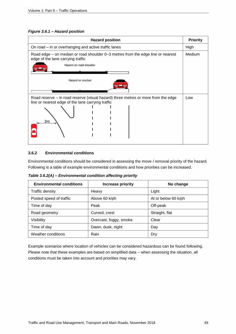
Volume 1: Part 9 – Traffic Operations
Traffic and Road Use Management, Transport and Main Roads, November 2018 49
Figure 3.6.1 – Hazard position
Hazard position Priority
On road – in or overhanging and active traffic lanes High
Road edge – on median or road shoulder 0–3 metres from the edge line or nearest edge of the lane carrying traffic
Medium
Road reserve – in road reserve (visual hazard) three metres or more from the edge line or nearest edge of the lane carrying traffic
Low
3.6.2 Environmental conditions
Environmental conditions should be considered in assessing the move / removal priority of the hazard.
Following is a table of example environmental conditions and how priorities can be increased.
Table 3.6.2(A) – Environmental condition affecting priority
Environmental conditions Increase priority No change
Traffic density Heavy Light
Posted speed of traffic Above 60 k/ph At or below 60 k/ph
Time of day Peak Off-peak
Road geometry Curved, crest Straight, flat
Visibility Overcast, foggy, smoke Clear
Time of day Dawn, dusk, night Day
Weather conditions Rain Dry
Example scenarios where location of vehicles can be considered hazardous can be found following.
Please note that these examples are based on simplified data – when assessing the situation, all
conditions must be taken into account and priorities may vary.
Volume 1: Part 9 – Traffic Operations
Traffic and Road Use Management, Transport and Main Roads, November 2018 50
Table 3.6.2(B) – Examples of scenarios considered hazardous
Position Conditions Priority
On road Under all conditions a vehicle on the road is a high priority High
Road edge Peak, low speed, day time Medium
Road reserve Peak, low speed, day time Low
Peak, high speed, crest, curve, night, narrow road Medium / high
3.7 Vehicles causing a hazard
Vehicles stopped on a road can pose a serious hazard to other motorists as well as the occupants of
the stopped vehicles.
Generally, vehicles causing a hazard are categorised as crash, stationary and abandoned. The
approach to each will vary depending on whether or not the motorist is present.
Once it has been determined that a vehicle is a hazard, generally it is moved as soon as practically
possible in line with hazard prioritisation.
3.7.1 Crashed vehicles
3.7.1.1 Police attendance at crash
Extract for drivers from the QPS website:
As of 1 January 2015, a police officer is required to attend the scene of a crash only when one
of the 'police attendance criteria' is met.
Police also have the discretion to attend and investigate traffic crashes in which there exists a
compelling public interest to do so – for example, crashes involving dangerous operation of a
motor vehicle or where there is significant damage caused to public infrastructure.
‘Police attendance criteria’
You must stop at the scene and call 000 (triple zero) if there is an emergency or any of the
following 'police attendance criteria' are met –
1. death or injury (requiring medical attention from a qualified ambulance officer, nurse
or doctor)
2. a hazardous environment or threat to public safety, including traffic congestion (e.g.
fuel spill, power lines down).
If police are required to attend the traffic crash, call 000 (triple zero) and request police. If the
Queensland Fire and Emergency Service (QFES) or the Queensland Ambulance
Service (QAS) is also required, please telephone 000 (triple zero) immediately.
You must stop at the scene and call Policelink on 131 444 if any of the following 'police
attendance criteria' are met –
1. suspected involvement of drugs and/or alcohol
2. a driver fails or has failed or is refusing to provide required details
3. a driver with an impairment or disability requires police assistance.

Volume 1: Part 9 – Traffic Operations
Traffic and Road Use Management, Transport and Main Roads, November 2018 51
Otherwise
• exchange information with other persons involved in the traffic crash
• arrange for movement of the vehicles involved in the crash (if safe to do so), and
• where required, report the crash to the Queensland Police Service within 24 hours.
This does not include if you have returned to your unattended vehicle and very minor damage
has been caused by an unknown vehicle and the other driver has already left the scene
without exchanging details. In this instance, you must report the matter to a police station.
This information, and more, is located at:
https://www.police.qld.gov.au/programs/roadSafety/tcfaq.htm#01.
A QPS traffic crash flyer is also available for download at:
https://www.police.qld.gov.au/programs/roadSafety/Documents/Traffic%20Crash%20Flyer.PDF.
3.7.1.2 Minor motor vehicle crash
In minor crashes, it may not be necessary for motorists to remain at the incident scene. Minor motor
vehicle crashes are crashes where:
• nobody is injured
• none of the vehicles involved require towing
• no alcohol, drugs or any other illegal activity is suspected, and
• driver particulars have been shared.
In these instances, TIMS personnel may encourage motorists to move their vehicles from the road.
3.7.1.3 Serious motor vehicle crash
A vehicle may not be cleared from the roadway without Police approval when there is evidence of a
serious motor vehicle crash. Refer to Section 3.7.1.1 Police attendance at crash for more detail.
3.7.2 Stationary / abandoned hazardous vehicles where a motorist is not present
If it is not possible to locate a motorist associated with a hazardous vehicle; once the vehicle has been
determined not to be of Police interest, it should be cleared in line with regional clearance priorities.
In these situations, the vehicle will typically be towed in line with regional procedures.
There is no set timeframe for when a vehicle is deemed abandoned. Each region should determine an
appropriate timeframe.
3.7.3 Stationary hazardous vehicles where a motorist is present
Vehicles in hazardous positions may have a motorist present. This is common where a vehicle has
broken down or been involved in an incident. In these situations, the TIMS officer will need to
approach and interact with the motorist.
Volume 1: Part 9 – Traffic Operations
Traffic and Road Use Management, Transport and Main Roads, November 2018 52
3.7.4 Towing arrangements
The following provisions apply to towing for vehicle breakdowns, not to vehicles that have been
involved in crashes.
• For motorists with some form of vehicle breakdown membership (for example, RACQ), inform
the TMC / regional office which can, if required, call the agency on behalf of the member.
• For non-members, on some roads in south-east Queensland, Transport and Main Roads has
a Stationary Vehicle Management contract for the towing to safety of vehicles not involved in a
crash (generally the nearest service station). Where tow-to-safety services are offered, all
actions should be performed in line with regional procedures. This is coordinated through the
TMC / regional office.
• If a motorist is unable or unwilling to move the vehicle off the road or arrange for a tow (for
example, if the motorist does not have funds available or the tow companies refuse to tow),
contact the Police or delegated officer who may then direct the removal of the vehicle.
3.7.4.1 Tow trucks and towing companies
A good relationship between TIMS personnel and towing companies / operators can greatly assist
activities at an incident site. It is important to be mindful that towing companies are generally
competing for the tow of accident and breakdown vehicles and there are therefore strict limitations
governing relationships to ensure impartiality and ethical behaviour.
TIMS personnel should:
• refer the call-out of tow companies to the TMC, regional office or Police tow
register (dependant on local procedures)
• never accept gifts (for example, spotter's fees / bribes) and report any offer to their supervisor
as soon as possible
• stay out of any discussions between the towing operator and the customer, no matter how
much you may wish to intervene
• be aware that a towing contractor is legally required to clean up car smash debris; however,
TIMS personnel have no authority to enforce this and must never direct a towing operator to
do so
• report any unlawful actions of other services at the scene to the Police.
Volume 1: Part 9 – Traffic Operations
Traffic and Road Use Management, Transport and Main Roads, November 2018 53
TIMS personnel should not:
• accept gifts (for example, spotter's fees / bribes) and report any offer to their supervisor as
soon as possible
• recommend or suggest any particular towing operator to any member of the public
• 'authorise' the movement or removal of a stationary vehicle, irrespective of the driver being
present or not
• argue with a towing operator or direct them to do anything (TIMS personnel have no legal
authority)
• offer advice as to the 'best way' to salvage an accident vehicle from an awkward crash
position
• call for extra resources to clear car smash debris.
Note: if infrastructure damage debris is evident, contact the TMC / regional office to arrange for removal
3.8 Debris causing a hazard
Debris on a high-speed road can pose a serious hazard to motorists. Early removal will lessen the
chances of an incident / accident.
3.8.1 Conditions for debris removal
If any of the following conditions are not satisfied, or if the TIMS personnel has any other personal
safety concerns, an alternate method of recovery must be considered; for example, for debris on a
motorway, other than immediately adjacent a shoulder with good visibility, the TMC should be
contacted to arrange alternative removal options.
TIMS personnel, operating alone, shall only recover debris with the physical attributes that conform
to the all of the following:
• a single piece item
• an item easily picked up by one hand, considering both size and weight
• an item that, if left on the carriageway, could cause an immediate incident / accident
• can be recovered within five minutes.
TIMS personnel, operating alone, shall only recover debris in locations that conform to all of the
following:
• from a lane immediately adjacent to a shoulder
• where the shoulder is sufficiently wide to accommodate the TIMS vehicle
• where there is a minimum 300 m clear view of oncoming traffic.
3.8.1.1 Notes on clear view and speed approach
In a 110 km/hr zone, vehicles are approaching at a nominal speed of 31 m per second. For this
reason, four seconds is allowed for retrieval. In this time, a vehicle will have moved 124 m closer.
Using a safety factor of 2.5, 300 m of clear lane is required prior to retrieval.
Always be aware and looking for errant drivers who are speeding or deliberately driving towards you.
Volume 1: Part 9 – Traffic Operations
Traffic and Road Use Management, Transport and Main Roads, November 2018 54
3.8.2 Arrival at debris site
At the debris scene, depending on the situation:
• park 25 m (or appropriate distance based on situation) behind the debris site, on shoulder
• apply appropriate signage, which may vary, pending the circumstance
• be aware of vehicles changing lanes
• always face and monitor approaching traffic.
3.8.2.1 Conduct risk assessment and options
Prior to retrieving any debris, a risk assessment must be conducted, then proceed as per procedures;
vehicles with attenuation may be required.
If the risk is assessed as acceptable, contact the TMC where available and advise intention to
remove debris. Where possible, arrange for variable message sign warning message if a variable
message sign is suitably located.
If the risk is not acceptable, contact the TMC operator and request rolling blockade to retrieve debris.
If a rolling blockade has been requested, the TIMS personnel should normally remain at the site, if
safe to do so, providing some level of warning of the hazard. This includes:
• remain on shoulder with left or right arrow displayed as appropriate
• consult with TMC operator where available regarding possible variable message sign
message, QLDTraffic / 13 19 40 and public information through radio stations.
3.8.3 Removing the debris
Such assessment and action shall consist of, but not necessarily be limited to:
• ensure the appropriate Traffic Guidance Scheme (TGS) selected for the situation meets all the
requirements and a satisfactory risk assessment
• consult with the TMC to see if any CCTVs are in the area can monitor your welfare during the
removal
• Change the arrow board configuration to Arrow Left or Arrow Right depending on the debris in
lane configuration – this will lead to some of the approaching motorists moving from the
affected lane
• face approaching traffic adjacent to the hazard on the shoulder
• monitor motorist behaviour in moving out of affected lane
• await clear approach of minimum 300 m (more if indicated by risk assessment)
• when the approach lane is clear, walk out facing the traffic, pick up the object and walk back
off the road – the time allowed for this activity is four seconds
• secure the item for later debris collection
• confirm with TMC that the hazard has been removed and request any variable message sign
boards initiated for the hazard to be removed.
Volume 1: Part 9 – Traffic Operations
Traffic and Road Use Management, Transport and Main Roads, November 2018 55
3.9 Spills causing a hazard
Any spill of oil or fuel or other debris needs to be cleaned from the road surface. At an incident scene,
TIMS personnel need to check for spills on the road pavement and, if safe and appropriate, apply
absorbent material as required, sweep up and bag after use.
TIMS personnel shall keep a safe distance from any hazardous, flammable or explosive chemicals.
Their role is primarily to assist in traffic control / management at the outer cordon of the incident site,
not to respond within the inner cordon where spills are most likely.
3.9.1 Chemical spills (HAZMAT)
HAZMAT incidents include not only actual spillage of hazardous chemicals, but the presence at the
incident scene of unbreached hazardous chemical containers in vehicle or otherwise.
If there is any concern that the vehicle or load to be moved / removed could pose a risk to personal
safety due to HAZMAT issues, the QFES should be contacted. Responders should proceed as per
QFES direction.
When TIMS personnel is the first responder at a possible HAZMAT scene:
• keep clear / upwind / uphill of any spill or suspicious vehicle / container
• install traffic control devices to slow / stop / divert traffic at the scene, using applicable lane
closure procedures
• if it can be safely done, approach the vehicle from the upwind side and identify the chemical
from the ID placard on the vehicle – refer to the HAZMAT sheet if available for interpretation
• advise the TMC to notify the QFES of placard details.
When approaching a HAZMAT incident where QFES is already in attendance, contact QFES through
the TMC to obtain:
• QFES-preferred approach route
• QFES-preferred stopping location.
3.9.2 Using absorbent spill removal material (‘kitty litter’)
There is a variety of absorbent products for use with spills, often referred to as 'kitty litter'.
Used kitty litter should be collected and bagged and either removed or left for later collection during
normal working hours.
PPE, including eye protection, must be worn when responding with the use of kitty litter.
TIMS personnel may also be requested by Emergency Services to bring kitty litter to an incident
scene. This is a valid TIMS callout. While at the scene, TIMS personnel should review the site for
additional traffic control requirements.
3.10 Providing traffic control / management
3.10.1 Overview
Providing traffic control / management at an incident helps move road users safely and expeditiously
around or past an incident, reduces the likelihood of secondary traffic crashes, and keeps motorists off
the surrounding road system.
Volume 1: Part 9 – Traffic Operations
Traffic and Road Use Management, Transport and Main Roads, November 2018 56
TIMS personnel should always:
• use safe practices for accomplishing tasks in and near traffic
• be aware of your visibility to oncoming traffic
• take measures either to move the traffic incident as far off the travelled roadway as possible or
to provide appropriate warning of blocked lanes
• set up appropriate temporary traffic management
• request additional traffic management if the incident will not be cleared rapidly or required
• reassess temporary traffic management regularly.
3.10.1.1 Placing traffic control devices on roads
Generally, TIMS personnel do not have the delegation to install or remove official traffic signs, this is
usually held by TMC personnel. TIMS personnel act under the direction of the TMC or an
appropriately delegated officer.
3.10.1.2 Effect a road closure
Generally, TIMS personnel do not officially close a road – they typically act under the direction of the
TMC or other authorised officer with legal delegations (this could include QPS, QFES or Transport and
Main Roads) to close / open a road.
3.10.1.3 Perform traffic control
TIMS personnel that have this delegation – that is, they are an accredited Traffic Controller – can only
operate within the conditions of their accreditation.
Volume 1: Part 9 – Traffic Operations
Traffic and Road Use Management, Transport and Main Roads, November 2018 57
5.1.6 Incident detection and verification
5.1.6-1 Help phone (roadside emergency phones)
The planning and operational installation decisions for emergency / help phones should be undertaken
in accordance with the following Transport and Main Roads documents:
• Engineering Policy EP149 Managed Motorways
• IMD Advice Note 3: New help phones on current and future projects (as of November 2018,
to request a copy of this internal document).
The design and technical specifications of emergency / help phones should be undertaken in
accordance with the following Transport and Main Roads documents:
• Road Planning and Design Manual (RPDM) 2nd edition Volume 3 Guide to Road Design,
Supplement to Part 6B Roadside Environment
• Road Planning and Design Manual (RPDM) 2nd edition Volume 5: Intelligent Transport
Systems
• MRS221 Help Phones, Specification (Measurement)
• MRTS221 Help Phones, Technical Specification

Volume 1: Part 9 – Traffic Operations
Traffic and Road Use Management, Transport and Main Roads, November 2018 58
5.2 Planned and special event management
5.2-1 Special events affecting roads in Queensland: A guide to securing approvals
This document is for Event Organisers seeking the approvals required by Queensland legislation to
run a special event on or affecting roads.
This document should be read together with Events in Queensland handbook – Best practice
guidelines for event delivery in Queensland Version 1.3, published by the Department of the Premier
and Cabinet, and available on
https://www.qld.gov.au/about/events-awards-honours/events/running-events
1 What is a special event?
A special event is defined by the Queensland Transport Operations (Road Use Management –
Accreditation and Other Provisions) Regulation 2015 as an event:
special event means an event—
(a)the conduct of which requires the use of roads and involves, or may reasonably be
expected to involve, some inconsistency with the requirements of—
(i)the Vehicle Standards and Safety Regulation; or
(ii)the Queensland Road Rules; and
(b)the nature of which is—
(i)wholly, or generally, public; and
(ii)ordinarily, though not necessarily, unique or occasional.
Examples of special events—
charity collections at traffic lights, fun runs, group bicycle rides for charity, walkathons.
Special events may include:
• competitive events, such as cycling races, triathlons, foot races, fun runs and walks or similar
activities that are wholly or partly conducted on public roads
• recreational events, such as large commercial tours, community rides or walks and fundraising
rides / walks, or similar activities that are wholly or partly conducted on public roads or affect
the operation of adjacent roads, or
• static events, such as concerts, festivals, carnivals and outdoor shows held in a fixed location,
but which may still need approval because of their effect on adjacent roads.
2 Obtaining approval to conduct a special event
By Queensland law, event organisers are required to obtain written approval from the apply for
Queensland Police Service (QPS), approval to conduct special events. The consent of the and road
owners such as local council or the Department of Transport and Main Roads.is also required.
Reference to the Events in Queensland Handbook – Best practice guidelines for event delivery in
Queensland provides useful information and guidance for anyone considering running an event.
Volume 1: Part 9 – Traffic Operations
Traffic and Road Use Management, Transport and Main Roads, November 2018 59
3 Event planning
During the planning of the event, the Event Management Plan (EMP) is the key coordination tool to
ensure the informed participation and active involvement of many government agencies, organisations
and community leaders. An EMP template is available on the Events in Queensland website at:
https://www.qld.gov.au/about/events-awards-honours/events/running-events.
A Traffic Management Plan (TMP) is required. Further information on preparing a TMP follows in this
supplement.
3.1 Seeking approvals
By Queensland law, Event Organisers are required to apply for approval to conduct special events.
The consent of both Police and the road owners is also required.
3.2 Traffic management
A Traffic Management Plan (TMP) for the event must be developed in conjunction with the EMP. The
TMP details all the measures which will be undertaken by the Event Organisers to manage the event
route and to minimise the various effects on the surrounding road networks. The TMP will include one
or more Traffic Guidance Schemes (TGS/s) which detail the signs and devices required to manage
traffic (including pedestrians and cyclists). The TMP must include detailed maps showing the route,
distances, directions and estimated timings for the progress of participants. A sub-section on traffic
control should include details on how intersections, road crossings and event-related parking traffic
and spectator movements will be managed.
The TMP and supporting TGS/s must be developed and signed off by a qualified traffic management
designer (as per Transport and Main Roads’ Manual of Uniform Traffic Control Devices (MUTCD)).
The Transport and Main Roads’ MUTCD Part 3: Works on Roads contains further information. This
document can be downloaded from the Transport and Main Roads website (search for ‘Technical
Documents’ in the ‘Business and Industry’ section of the site) at:
https://www.tmr.qld.gov.au/business-industry/Technical-standards-publications/Manual-of-
uniform-traffic-control-devices.
There is additional information for designers on event traffic management in the department's Event
Traffic Management Design Guidelines available at:
https://www.tmr.qld.gov.au/Community-and-environment/Planning-and-development/Other-
matters-requiring-approval/Traffic-management-at-special-events
The Transport and Main Roads website is also a source of maps, detailing all state-controlled roads.
3.3 Choosing suitable roads
When deciding the route for a special event, the following factors should be considered:
• Certain roads may not be available at certain times of the day. Major roads may not be safe or
suitable for special events during peak traffic periods or where alternative routes are not
available to the travelling public.
• For safety reasons, roads that are heavily used by freight may be unsuitable or involve
extensive event conditions.

Volume 1: Part 9 – Traffic Operations
Traffic and Road Use Management, Transport and Main Roads, November 2018 60
• Avoid routes which cross busy, high-speed roads because such crossings may need major
changes to existing traffic arrangements or substantial additional resources to manage the
crossing safely.
• Roads used by public transport (for example, trams and buses) may not be safe or suitable
depending on service frequency, road width and other factors. Consult with the public
transport operator when preparing the EMP / TMP.
• It is not advisable to hold special events during periods when traffic volumes are high (for
example, long weekends, start and finish of school holidays).
• Events should always aim to minimise impacts on pedestrian and road user access, retail and
business operations, public transport operations and local residents’ access.
• For safety reasons, special events should preferably be conducted during daylight hours.
• It is desirable for safety reasons for an event route to have mostly left turns at major
intersections rather than right turns.
• Event routes, particularly when road closures and off-road paths are used, must be planned
and managed to permit quick and easy entry and exit access for emergency vehicles.
• Liaise closely with the Council if an event is to be terminated at a busy precinct or shopping
centre.
• Events which require the closure of motorways and major arterial roads are rarely acceptable.
If acceptable, the road owner may only tolerate a low frequency of interruptions to
normal operations, due to road performance obligations. Approval is more likely to be granted
for on-road events which seek to use lower speed and lower traffic volume roads and
alternative routes to major arterial roads.
• As it is against the law to race on public roads, a special event involving competitive racing
should plan to use roads which can be temporarily closed or by effecting lane closures.
Holding competitive road races in 'live' traffic conditions presents major safety concerns to
both the competitors and other road users and is unlikely to receive approval.
• The closure of a road for a special event allows participants to travel safely, removed from
general traffic. Under a Special Event permit, riders may be exempted from compliance with
specific requirements of Vehicle Standards, Safety Regulation and the Queensland Road
Rules.
3.4 Devices for traffic control
This sub-section of the TMP must explain in detail how it is proposed to manage any road closures,
road crossings, route turnings and route hazards (rail crossings, narrow bridges and so on) to ensure
the safe operation of the event.
The traffic control section must specify where all directional and guidance signs will be erected to
manage event participants and spectators and where barriers and traffic cones will be placed to direct
motor vehicle and pedestrian traffic in the area.
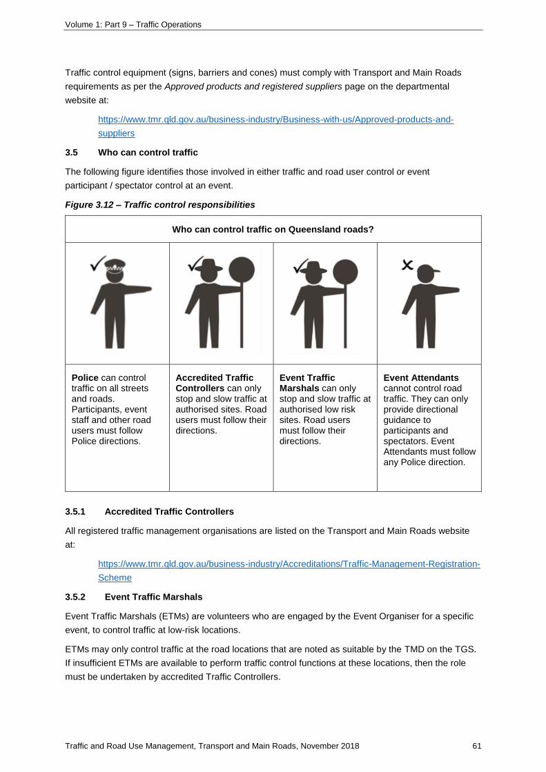
Volume 1: Part 9 – Traffic Operations
Traffic and Road Use Management, Transport and Main Roads, November 2018 61
Traffic control equipment (signs, barriers and cones) must comply with Transport and Main Roads
requirements as per the Approved products and registered suppliers page on the departmental
website at:
https://www.tmr.qld.gov.au/business-industry/Business-with-us/Approved-products-and-
suppliers
3.5 Who can control traffic
The following figure identifies those involved in either traffic and road user control or event
participant / spectator control at an event.
Figure 3.12 – Traffic control responsibilities
Who can control traffic on Queensland roads?
Police can control traffic on all streets and roads. Participants, event staff and other road users must follow Police directions.
Accredited Traffic Controllers can only stop and slow traffic at authorised sites. Road users must follow their directions.
Event Traffic Marshals can only stop and slow traffic at authorised low risk sites. Road users must follow their directions.
Event Attendants cannot control road traffic. They can only provide directional guidance to participants and spectators. Event Attendants must follow any Police direction.
3.5.1 Accredited Traffic Controllers
All registered traffic management organisations are listed on the Transport and Main Roads website
at:
https://www.tmr.qld.gov.au/business-industry/Accreditations/Traffic-Management-Registration-
Scheme
3.5.2 Event Traffic Marshals
Event Traffic Marshals (ETMs) are volunteers who are engaged by the Event Organiser for a specific
event, to control traffic at low-risk locations.
ETMs may only control traffic at the road locations that are noted as suitable by the TMD on the TGS.
If insufficient ETMs are available to perform traffic control functions at these locations, then the role
must be undertaken by accredited Traffic Controllers.

Volume 1: Part 9 – Traffic Operations
Traffic and Road Use Management, Transport and Main Roads, November 2018 62
ETMs must comply with the Special Event Traffic Marshal Approved Procedure. This document can
be downloaded from the Transport and Main Roads website at:
https://www.tmr.qld.gov.au/Community-and-environment/Planning-and-development/Other-
matters-requiring-approval/Traffic-management-at-special-events/Event-Traffic-Marshals.
3.5.3 Event Attendants
The Event Organiser is responsible for providing adequate Event Attendants at all major road
intersections and any other road intersections and points where conflict with motor vehicles may
occur, to provide forewarning to event participants. The EMP should include details of the locations
and functions of Event Attendants required to warn and direct event participants along the event route.
Event Attendants can only staff main road intersections if Police or accredited Traffic Controllers are in
attendance to manage traffic.
All Event Attendants must be briefed on their responsibilities; be suitably identified; be equipped with
adequate means of communication; and must wear high-visibility clothing that complies with Australian
Standard AS/NZS 4602: 2011.
Event Attendants or staff must not control or attempt to control traffic on a road, unless they are
engaged as an Event Traffic Marshal for the event.
3.6 Event parking and access
The EMP / TMP should detail how the parking needs for the event will be accommodated with
appropriately located sites, directional signage and Event Attendants. Event parking should include
parking areas for cars and buses, including locations for any essential or emergency vehicles,
participants, officials, spectators, media, event staff and medical vehicles. Spectator and participant
car parking and associated vehicle movements should be carefully considered in pre-event planning.
Every effort should be made by Event Organisers to encourage participants, supporters and
spectators to use alternative routes to access the event and, where possible, to use public transport
as an alternative to car travel.
Where coordinated public transport is organised for event participants and supporters, the EMP / TMP
should contain relevant details of such arrangements and key personnel contacts.
3.7 Escort vehicles
The EMP / TMP must include details of the number and placement of escort vehicles.
If an event is a race that involves a small number of participants on a road which is open to the public,
at least two escort vehicles must be provided. Escort vehicles would normally be positioned behind the
participants on a divided road and in front of, and behind the participants on an undivided road. Escort
vehicles must display flashing yellow lights, and suitable signs.
4 Contacts
4.1 Councils
A current list of all Queensland Councils and their contact details is available on the Queensland
Department of Local Government and Planning's website.
Volume 1: Part 9 – Traffic Operations
Traffic and Road Use Management, Transport and Main Roads, November 2018 63
4.2 Queensland Police
For events within a single Police region, contact the local Police station. Events involving multiple
Police regions are coordinated by the Police Road Policing Unit (Road-Based Events) in Brisbane.
Search ‘special events’ on the Police website for details.
4.3 Transport and Main Roads
A listing of Transport and Main Roads Regional offices can be found on the departmental website at:
https://www.qld.gov.au/transport/contracts/roads
4.4 Other road owners
Refer to websites of toll road operators, bus way operators and private road owners / managers.
5 Additional resources
The following documents and websites are a useful source of further information on the different
approvals processes, the preparation of an EMP and events organisation.
The Department of the Premier and Cabinet publishes best practice advice for event delivery in
Queensland at:
https://www.qld.gov.au/about/events-awards-honours/events/running-events.
The Queensland Police Service website has information on the Police approvals process at
https://www.police.qld.gov.au/online/Register-an-Event.htm.
Transport and Main Roads publishes information on traffic management at special events at:
https://www.tmr.qld.gov.au/Community-and-environment/Planning-and-development/Other-
matters-requiring-approval/Traffic-management-at-special-events.
Its register of all companies accredited prequalified to provide traffic management services on
state-controlled roads is published at:
https://www.tmr.qld.gov.au/business-industry/Business-with-us/Approved-products-and-
suppliers/Traffic-engineering-and-road-safety-approved-products.
Technical manuals and information on traffic management and road signs are published at:
https://www.tmr.qld.gov.au/business-industry/Technical-standards-publications.
Gold Coast City Council and Brisbane City Council have forms and information for special events
organisers available at:
• http://www.goldcoast.qld.gov.au/thegoldcoast/event-organisers-22394.html
• https://www.brisbane.qld.gov.au/laws-permits/laws-permits-businesses/events-venues-
filming/events-festivals.
Tourism and Events Queensland has a useful guide Queensland events guide available at
https://teq.queensland.com/industry-resources/how-to-guides/queensland-events-guide.
Cycling Queensland provides advice to its affiliated clubs on preparing race management plans for
organised road race events at
http://www.qld.cycling.org.au/Events/Event-Management-Resources.
Volume 1: Part 9 – Traffic Operations
Traffic and Road Use Management, Transport and Main Roads, November 2018 64
6 Systems and procedures for arterial traffic control – traffic signals
6.4 Movements and phases
6.4-1 Movements and phases in Queensland
AGTM sections 6.4.1 to 6.4.3 apply to Queensland but must be read in conjunction with current
Transport and Main Roads road safety policy. At the time of writing, Appendix A Safety Intervention
and Improvement Guidelines (Interim) of the Road Safety Policy document signed by the
Director-General in August 2018 defines default requirements for filtering, pedestrian protection and
slip lanes. These default requirements will apply unless justification is given in a planning, design
exception or a risk assessment report.
Sections 6.4.3-1 to 6.4.3-6 following provide additional information regarding provision of U turns, right
turn filtering arrangements and pedestrian detection that again must be read in conjunction with
current Transport and Main Roads road safety policy.
Volume 1: Part 9 – Traffic Operations
Traffic and Road Use Management, Transport and Main Roads, November 2018 65
6.4.3 Phasing design
6.4.3-1 Provision of U-turns at traffic signals
1 General principles
U-turns should only be permitted at signalised intersections where:
a) the intersection approach has a raised median
b) the approach has an auxiliary right-turn lane
c) geometry is sufficient to allow the U-turn to be made in one continuous manoeuvre by vehicles
of the type likely to turn
d) there is adequate visibility of approaching vehicles
e) there would be no danger to pedestrians
f) there are no more than two lanes of opposing through traffic
g) there is no left turn green arrow (signal) control in the road to the right.
h) where a fully controlled right-turn phase is provided, Items (d) and (f) above may not be
relevant).
Where there is sufficient width for a vehicle to store clear of through traffic and the lack of an auxiliary
right-turn lane would not affect traffic flow and cause delays and crashes.
2 Factors limiting U-turns at signals
U-turns should not be provided at signalised intersections where:
a) the intersection is a very high volume intersection
b) the provision of U-turns at the signals alters phasing arrangements at the intersection,
adversely affecting good progression along the route
c) their provision would significantly affect safety or traffic operating conditions at the signals (for
example, delays)
d) their introduction would cause an unexpected conflict with pedestrians or motor vehicles, for
example, with a left turn green arrow (signal) control in the road to the right
e) the right-turn volume is substantial and U-turn movements represent 65% or more of the total
right-turn volume
f) there is adequate opportunity either upstream or downstream of the signals to safely carry out
a U-turn at a median opening
g) right turns have been generally prohibited along the route (for example, due to limited road
width) and access is provided by means of alternate ‘loop’ routes instead, unless the
intersection is important from a road network perspective and a U-turn can be properly
provided.
3 Geometric design
Refer to the Road Planning and Design Manual, Austroads Guide to Road Design and the Austroads
Design Vehicles and Turning Path Templates for geometric design requirements

Volume 1: Part 9 – Traffic Operations
Traffic and Road Use Management, Transport and Main Roads, November 2018 66
4 Signal displays
U-turns at traffic signals (when permitted by the U-TURN PERMITTED sign R2-15) should only be
permitted when a green circle aspect or green signal right-turn arrow is displayed. The right-turn red
arrow should be used to prevent ‘filter’ turns where the sight distance to oncoming vehicles is
inadequate.

Volume 1: Part 9 – Traffic Operations
Traffic and Road Use Management, Transport and Main Roads, November 2018 67
6.4.3-2 Control of right-turn movements at traffic signals
1 Definitions
Filter turn
A turning movement that must give way to and find safe gaps in conflicting (opposing) vehicle or
pedestrian before proceeding, e.g. filter right-turn, slip-lane left turn, turn on red. Also called Opposed
Turn. This is also known as a permitted movement.
Full control
Control of a turning movement using three-aspect (red, yellow, green) turn arrows on a six-aspect
signal face, where the green arrow indicates that the vehicle can turn unopposed (with no opposing
vehicle or pedestrian traffic) and the red arrow indicates that the vehicle is not permitted to turn (filter
turn not permitted). This is also known as protected only phasing.
Partial control
Control of a turning movement by a green arrow display in one phase (as an unopposed movement)
and by a green circle display in another phase (as a filter or opposed movement). This is known as
protected/permitted or permitted/protected phasing.
Part-time filter control
The right-turn is fully controlled at certain predetermined times of the day (or in predetermined plans
that are automatically selected by time of day or for certain traffic conditions), at other times it is
partially controlled.
Uncontrolled
No arrow phase (protected phase) is provided for the right-turn movement. Right-turning traffic must
make a filter turn. This is also known as permitted only phasing.
2 Part-time filter control
‘Full control’ operates during certain hours of the day and ‘filter only’ or ‘partial control’ operates during
other times of the day.
Where filter turns are desirable in order to decrease delay in periods of low traffic flow, but are
undesirable during periods of high traffic flows, then the red arrow should be displayed during the
periods of high flows and should be extinguished when adequate gaps are detected in the opposing
traffic flow (if this facility is available) or extinguished after a fixed duration derived from one of the
controller timing period (e.g., ‘the late start’ period, the ‘WALK’ period or the ‘minimum green’ period).
Part-time full control shall be used at appropriate times of day or in appropriate plans where it is
desirable to provide full control of a right-turn movement:
a) primarily because in higher flow conditions, it is quite likely that large vehicles waiting to turn
right from on the opposing approach would restrict visibility of the opposing through
movement, but in low flow conditions this is unlikely, and any restriction of visibility would be
minor, or
b) at times of the day when the opposing through movement is very heavy and the filtering
movement is deemed undesirable, but at other times of the day the filter movement is safe
and desirable for traffic efficiency.

Volume 1: Part 9 – Traffic Operations
Traffic and Road Use Management, Transport and Main Roads, November 2018 68
3 Methods of changing from full control to partial control
The simplest method of allowing part-time full control at certain times of the day is to include a data
parameter in the plan data which controls whether the arrow is allowed to drop off or not. This is
usually the Z+ or Z- signal. The default mode of operation for the controller must be full control of the
right turn. Where there is concern that a plan which allows right turn movement(s) to filter may be
called by dynamic plan selection at a time of day when the right turn filtering is not appropriate
alternative arrangements can be considered.
Volume 1: Part 9 – Traffic Operations
Traffic and Road Use Management, Transport and Main Roads, November 2018 69
6.4.3-3 Pedestrian protection
This supplement details pedestrian protection requirements at signalised intersections.
Where turning vehicles (both left and right) can conflict with a pedestrian movement, pedestrian
protection shall be provided by delaying the start of the vehicle movements. The length of the delayed
start depends on the type of pedestrians using the crossing, the flow of pedestrians and the flow of the
conflicting vehicles. However, a minimum of four seconds is required to allow pedestrians to establish
themselves on the crossing before vehicle movements begin. The length of the delayed start can be
varied by the time of day, such as at school entry and exit times.
Delayed starts shall only be used when a pedestrian demand is received and shall be provided by red
arrow signals. The only exception to the use of red arrow signals is at locations with very low
pedestrian demand (less than three pedestrian phase demands in the peak pedestrian movement
hour). In these situations, a delay to the entire vehicular phase may be considered.
At locations where pedestrians cross more than two lanes, the pedestrian detectors should be split.
This will minimise the operational impact by allowing a different duration of protection depending on
the direction of travel of the pedestrian. For example, consideration can be given to not delaying the
start for a short duration for farside demands (as it is often ineffective), or alternatively, the duration of
the delayed start for farside demands can be increased where necessary.
Where delayed starts are provided for left turning vehicles and the right turning vehicles opposing the
left turn, the right turn delayed start shall at least equal that for the left turn.
Volume 1: Part 9 – Traffic Operations
Traffic and Road Use Management, Transport and Main Roads, November 2018 70
6.4.3-4 Two-aspect signal controls of pedestrian crossings on slip lanes
This supplement provides advice about the use of two-aspect signal control of vehicles at signalised
pedestrian crossings on slip lanes and guidance on their installation and operation.
1 Principles
Two-aspect (yellow-red) vehicle signals may be used to control traffic on a slip lane allowing
pedestrians to cross on a green 'Walk' pedestrian signal. This arrangement should generally be used
where signals are required, as it results in significantly reduced delay for both pedestrians and
left-turning traffic.
The use of two-aspect (yellow-red) vehicle signals at a slip lane allows traffic to be stopped using the
usual yellow-red sequence, but there is no green display. When the traffic signals are not showing red
or yellow, the road rules require traffic on the slip lane to give way to all other traffic at the intersection.
2 Background
2.1 Disadvantages of three-aspect control of vehicles on a slip lane
The slip lane cannot be given a green signal if there is any conflicting traffic, including traffic filtering
right from the opposite approach. This can result in significant delays to the left-turning traffic which
can be perceived as unnecessary, frustrating drivers and often leading to a high rate of
non-compliance by both traffic and pedestrians.
If the left turn is signalled green when the adjacent through movement is green, the right turn from the
opposing approach cannot be allowed to filter. This results in considerable additional delay to other
road users and reduces the capacity and design life of the intersection.
2.2 Pedestrian non-compliance at signalised slip lanes
Slip lane pedestrian signals need to respond quickly to pedestrian demand, otherwise they will result
in a high level of pedestrian non-compliance which undermines the safety benefit of treatment.
3 Guidelines for design
The signal layout used should conform with the design principles of the Guide to Road Design.
Specifically, signals should be placed in positions to provide stopping and starting functions. A primary
signal should be provided, nominally 3 m from the left-hand end of the stop line. A
dual primary (right-hand primary) lantern is desirable to reinforce the stopping position and to provide
better sight lines for approaching traffic. Secondary and tertiary lanterns should be provided so that at
least two lanterns are visible from the stop line. Arrowed lanterns or inserts should be used in all
left-turn lanterns if there is confusion with the through movement lantern control. Pedestrian lanterns
and push buttons should be located in accordance with Austroads Guide to Road Design and MUTCD
Part 10.
Sufficient distance should be allowed between the stop line and the give way or merge lines to ensure
drivers understand the need to give way at the merge point. There should be space for at least a
single vehicle should be available past the crossing (to reduce the potential that vehicles queue on the
crossing). Guidance on signing and marking the merge point is given in Part 2 of the MUTCD. A give
way sign may be provided if indicted by MUTCD Clause 2.5.5.
Volume 1: Part 9 – Traffic Operations
Traffic and Road Use Management, Transport and Main Roads, November 2018 71
4 Phasing arrangement
While details of the signal group operation for the slip lanes should be site-specific, the general
principle is to let the slip lane vehicle signals go to red at any time. Consideration can, however, be
given to excluding the period when the parallel through movement has just started – that is, during the
inter-green preceding and the minimum green periods of the parallel through movement. The decision
to do this would be based on the geometry of the intersection, the length of any short left-turn lane and
the probability of it queueing back and restricting the flow of the through movement.
It should be noted that pedestrians would almost always have to push a button to cross the slip lane
and another to cross the main carriageway. Consideration should be given to the use of signs advising
pedestrians to press the second button to cross the subsequent crossing (R3-Q01 – WALK TO
ISLAND AND WAIT FOR FURTHER SIGNAL).
Wherever possible, the minimum green for traffic on the slip should be set so as to allow pedestrians
to cross the slip lane at least two points in each cycle of the intersection signals.
Volume 1: Part 9 – Traffic Operations
Traffic and Road Use Management, Transport and Main Roads, November 2018 72
6.4.3-5 Pedestrian detectors at intersections and mid-block signalised pedestrian
crossings (Smart crossings)
1 Introduction
This supplement provides guidance on smart pedestrian crossings in Queensland. It includes a
general description of operation and benefits and gives detailed design guidance for smart pedestrian
crossings.
Standard Australian signalised pedestrian crossings use a fixed timing and signal sequence. This can
result in unnecessary traffic delays, as traffic can be held on a red signal, after the pedestrians have
cleared the carriageway. Additionally traffic can be delayed unnecessarily when a pedestrian crosses
in a gap or chooses not to cross when the pedestrian push-button has been pushed.
Smart pedestrian crossings use pedestrian detectors to control the phase demand and the pedestrian
clearance time. They use the standard traffic signal displays and sequence with two additional
pedestrian detector systems to improve the operational efficiency and safety of the crossing. These
pedestrian detector systems are:
• Footpath Detectors:
Detectors that monitor pedestrians on the footpath (kerbside) adjacent to the push-button. The
intent is to ensure that traffic is not stopped if the pedestrians cross the road or leave the
footpath before the pedestrian phase is initiated.
• Carriageway Detectors:
Detectors monitoring pedestrians on the carriageway. The intent is to reduce traffic delay, by
starting the traffic as soon as pedestrians are clear of the crossing.
These two systems can be installed and operated independently.
Only pedestrian detectors approved by the department shall be used.
Table 1 – Definitions
TGSI (Tactile ground surface indicator)
Truncated cones and / or bars installed on the ground or floor surface designed to assist vision-impaired pedestrians to locate a crossing or pushbutton.
PELICAN (Pedestrians Light Controlled crossing)
Originally a UK specification for pedestrian crossings, and now used in some Australians states. The PELICAN presents a flashing yellow display to the drivers during most of the clearance period, where drivers are allowed to proceed if the pedestrians have cleared the crossing. The PELICAN crossing is NOT approved for use in Queensland.
Farside pedestrian lantern A lantern which is intended for the control of pedestrian traffic located on the other side of crossing. A farside lantern is in view for pedestrians throughout the crossing movement.
Nearside pedestrian lantern A lantern which is intended for the control of pedestrian traffic located on near side of crossing. A nearside lantern is in view for pedestrians at the kerbside, but not in view during the crossing movement.

Volume 1: Part 9 – Traffic Operations
Traffic and Road Use Management, Transport and Main Roads, November 2018 73
2 Background
The concept of smart pedestrian crossings is similar to that of the UK Puffin crossing.
The Puffin crossing (pedestrian user-friendly intelligent crossing) is a UK specification for pedestrian
crossings that uses pedestrian detectors and nearside pedestrian lanterns. Puffin crossings were
developed as an alternative to Pelican crossings to avoid the need for a flashing yellow display to
drivers during the pedestrian clearance period. This was due to some concern that the flashing yellow
display was not well respected by drivers.
Puffin facilities were developed in the late 1980s and early 1990s. In 2002, the use of Puffin crossings
were included in legislation for both mid-block, and intersection crossings. By 2008, Puffin crossings
formed approximately 30% of the mid-block crossing in the U.K.
It has been reported that in the U.K., Puffin crossings are replacing Pelican crossings.
In Queensland, smart crossings use the Puffin-style pedestrian detectors but do not include the use of
nearside pedestrian lanterns (refer to Appendix B). Queensland smart crossings use only the standard
farside pedestrian lanterns as used at existing intersections and crossings.
Trials of pedestrian detectors have been undertaken in Queensland. The first trial site was started
near Redbank in the late 1990s. The outcome of the trials was that pedestrian detectors were
unreliable and difficult to maintain. A number of successful trials were conducted in the late 2000s.
The footpath detectors were installed and operated correctly in Toowoomba, Townsville and Brisbane.
In 2014, Transport and Main Roads and City of Gold Coast Council set up another four smart
mid-block crossing trial sites.
In Victoria, carriageway detectors were installed at over 280 sites. VicRoads has developed device
specification and standard drawings for the application of carriageway detectors. Pedestrian detectors
have also been used in other Australian states, and New Zealand.
3 Benefits of smart pedestrian crossing
The major benefits of smart pedestrian crossings are to reduce traffic delays and improve safety.
3.1 Reducing traffic delays
Standard Australian signalised pedestrian crossings use a fixed timing and signal sequence. Field
trials have shown that some delays to traffic can be avoided by using pedestrian detectors.
At mid-block pedestrian crossings, unnecessary delays can typically be:
• over 10 seconds when pedestrians cross at a brisk walking pace
• two to three seconds when a large number of pedestrians cross the road, with some
pedestrians leaving the footpath at (or just past) the end of the green ‘Walk’ time
• over 20 seconds when a pedestrian crosses before the green ‘Walk’ time or does not cross at
all.
Smart crossings can be used at intersections where they will deliver similar benefits.
At intersections, smart crossings can improve traffic efficiency by reducing the time required for
pedestrian phases. They can also potentially improve traffic signal coordination by reducing the time
for pedestrian phases that conflict with major traffic flows. With slow moving pedestrians, the
clearance time will be as normal or greater as the longer clearance time will only run when required.
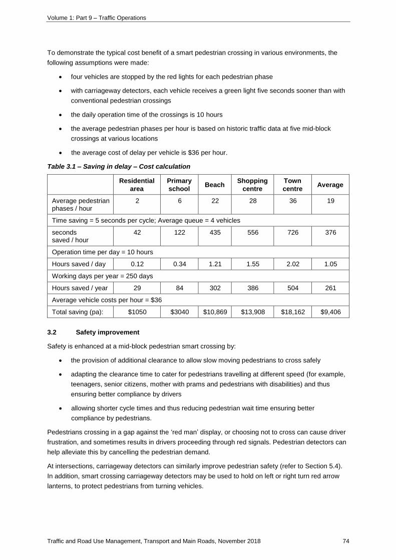
Volume 1: Part 9 – Traffic Operations
Traffic and Road Use Management, Transport and Main Roads, November 2018 74
To demonstrate the typical cost benefit of a smart pedestrian crossing in various environments, the
following assumptions were made:
• four vehicles are stopped by the red lights for each pedestrian phase
• with carriageway detectors, each vehicle receives a green light five seconds sooner than with
conventional pedestrian crossings
• the daily operation time of the crossings is 10 hours
• the average pedestrian phases per hour is based on historic traffic data at five mid-block
crossings at various locations
• the average cost of delay per vehicle is $36 per hour.
Table 3.1 – Saving in delay – Cost calculation
Residential
area
Primary
school Beach
Shopping
centre
Town
centre Average
Average pedestrian phases / hour
2 6 22 28 36 19
Time saving = 5 seconds per cycle; Average queue = 4 vehicles
seconds saved / hour
42 122 435 556 726 376
Operation time per day = 10 hours
Hours saved / day 0.12 0.34 1.21 1.55 2.02 1.05
Working days per year = 250 days
Hours saved / year 29 84 302 386 504 261
Average vehicle costs per hour = $36
Total saving (pa): $1050 $3040 $10,869 $13,908 $18,162 $9,406
3.2 Safety improvement
Safety is enhanced at a mid-block pedestrian smart crossing by:
• the provision of additional clearance to allow slow moving pedestrians to cross safely
• adapting the clearance time to cater for pedestrians travelling at different speed (for example,
teenagers, senior citizens, mother with prams and pedestrians with disabilities) and thus
ensuring better compliance by drivers
• allowing shorter cycle times and thus reducing pedestrian wait time ensuring better
compliance by pedestrians.
Pedestrians crossing in a gap against the ‘red man’ display, or choosing not to cross can cause driver
frustration, and sometimes results in drivers proceeding through red signals. Pedestrian detectors can
help alleviate this by cancelling the pedestrian demand.
At intersections, carriageway detectors can similarly improve pedestrian safety (refer to Section 5.4).
In addition, smart crossing carriageway detectors may be used to hold on left or right turn red arrow
lanterns, to protect pedestrians from turning vehicles.

Volume 1: Part 9 – Traffic Operations
Traffic and Road Use Management, Transport and Main Roads, November 2018 75
3.3 Other benefits
In addition to reducing traffic delays and improving safety, smart pedestrian crossings:
• provide environmental benefits, such as fuel saving, by reducing unnecessary start-stop or
running time of motor vehicles
• improve mobility and comfort for slow moving pedestrians: for example, pedestrians with
disabilities or impaired mobility.
4 Smart crossing facilities
Smart pedestrian crossings have the following components:
• carriageway detector
• footpath detector
• pedestrian push-button with demand-indicator
• ‘Cross with Care’ adhesive label (TC1471)
• pavement marking
• Tactile Ground Surface Indicator (TGSI)
• Traffic Signal Controller.
4.1 Carriageway detector
Carriageway detectors are the essential components of smart crossings. They are usually relatively
easy to install and configure and are cost-effective.
Figure 4.1 illustrates the typical arrangement of carriageway pedestrian detectors. The hatched area in
the diagram gives an approximate representation of the desired zone of detection.
Ideally, the detection zone should cover the whole area of the marked crossway. The actual detection
zone is based on many factors: for example, the mounting height of the detector and its vertical and
horizontal angles. For microwave detectors (as often used for carriageway detectors), the detection
zone also depends on the output power of the detector and the antenna used in the detector. Detailed
information should be sought from suppliers regarding the recommended mounting height and the
detection zone that can be achieved with the detectors being used.
Pedestrians outside the detection zone will not be detected and the pedestrian clearance time could
be terminated. Landscaping or appropriate fencing may be used to encourage pedestrians to cross
within the actual zone of detection. More guidance on the actual zone of detection is given in
Section 5.1.
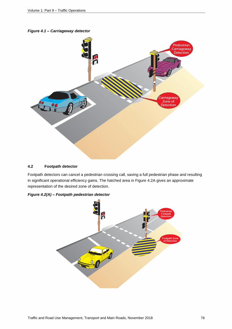
Volume 1: Part 9 – Traffic Operations
Traffic and Road Use Management, Transport and Main Roads, November 2018 76
Figure 4.1 – Carriageway detector
4.2 Footpath detector
Footpath detectors can cancel a pedestrian crossing call, saving a full pedestrian phase and resulting
in significant operational efficiency gains. The hatched area in Figure 4.2A gives an approximate
representation of the desired zone of detection.
Figure 4.2(A) – Footpath pedestrian detector

Volume 1: Part 9 – Traffic Operations
Traffic and Road Use Management, Transport and Main Roads, November 2018 77
Detailed information should be sought from suppliers regarding the detection range and mounting
height. Incorrect height or mounting may cause malfunction of detectors and risk to pedestrians.
Footpath detectors shall be accompanied by:
• pedestrian push-button with demand indicators
• specific ‘cross with care’ adhesive labels
• specific pavement marking.
The area of detection shall correspond to the area in which pedestrians actually stand. Pavement
marking encourages pedestrians to stand in the designated detection area (refer to
Section 4.5 Pavement marking). In addition to some form of pavement marking, landscaping or road
furniture may be used to direct pedestrians to stay in the designated area.
Two trial sites used fences and leaning rails to make pedestrians’ movement more
predictable (Figure 4.2(B)).
Figure 4.2(B) – Road furniture used in smart crossing
4.3 Pedestrian push-button with demand-indicator
Most pedestrian push-buttons in Queensland have no demand-indicator. But where footpath detectors
are used, demand-indicators shall be available to give pedestrians confirmation that their demand will
be serviced.
The demand will be cancelled, and the indicator switched off if the pedestrian moves outside the
detection zone.
If the demand-indicator goes off or does not come on, pedestrians can press and if necessary hold the
push-button to reinitiate and hold the demand.
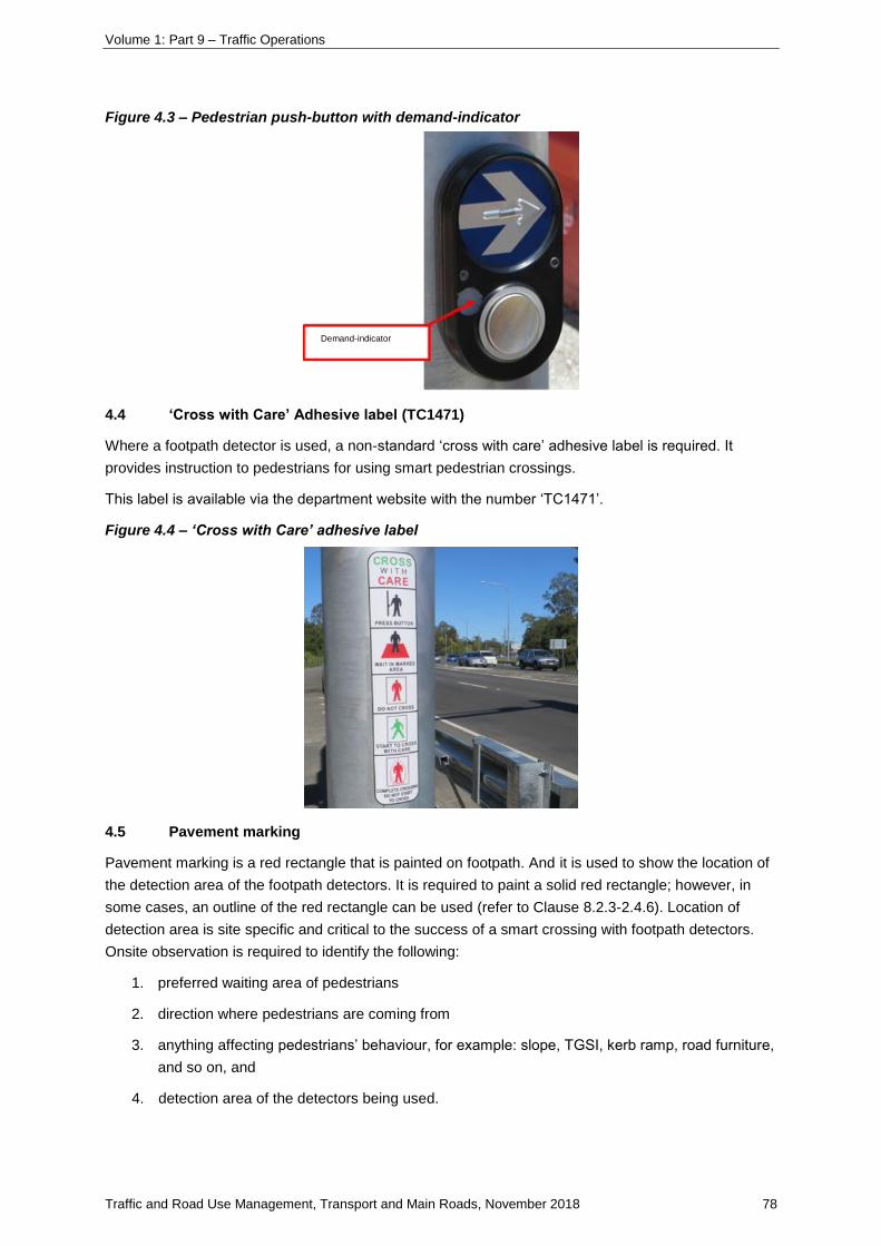
Volume 1: Part 9 – Traffic Operations
Traffic and Road Use Management, Transport and Main Roads, November 2018 78
Figure 4.3 – Pedestrian push-button with demand-indicator
4.4 ‘Cross with Care’ Adhesive label (TC1471)
Where a footpath detector is used, a non-standard ‘cross with care’ adhesive label is required. It
provides instruction to pedestrians for using smart pedestrian crossings.
This label is available via the department website with the number ‘TC1471’.
Figure 4.4 – ‘Cross with Care’ adhesive label
4.5 Pavement marking
Pavement marking is a red rectangle that is painted on footpath. And it is used to show the location of
the detection area of the footpath detectors. It is required to paint a solid red rectangle; however, in
some cases, an outline of the red rectangle can be used (refer to Clause 8.2.3-2.4.6). Location of
detection area is site specific and critical to the success of a smart crossing with footpath detectors.
Onsite observation is required to identify the following:
1. preferred waiting area of pedestrians
2. direction where pedestrians are coming from
3. anything affecting pedestrians’ behaviour, for example: slope, TGSI, kerb ramp, road furniture,
and so on, and
4. detection area of the detectors being used.
Demand-indicator
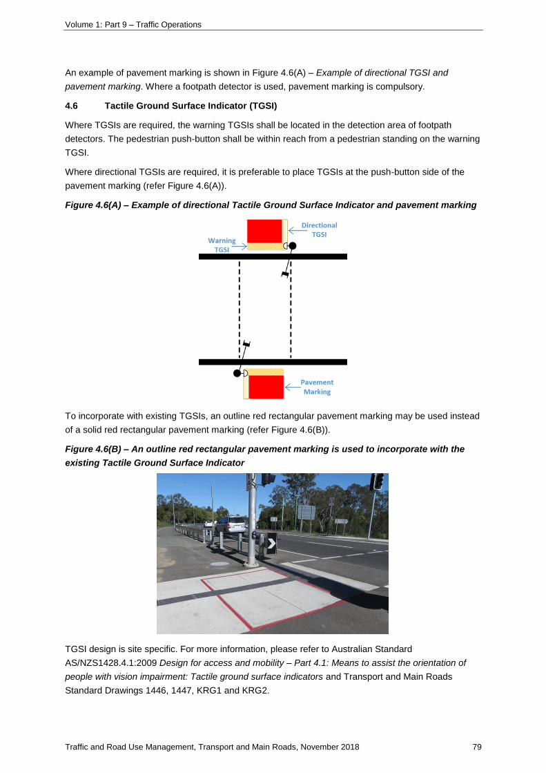
Volume 1: Part 9 – Traffic Operations
Traffic and Road Use Management, Transport and Main Roads, November 2018 79
An example of pavement marking is shown in Figure 4.6(A) – Example of directional TGSI and
pavement marking. Where a footpath detector is used, pavement marking is compulsory.
4.6 Tactile Ground Surface Indicator (TGSI)
Where TGSIs are required, the warning TGSIs shall be located in the detection area of footpath
detectors. The pedestrian push-button shall be within reach from a pedestrian standing on the warning
TGSI.
Where directional TGSIs are required, it is preferable to place TGSIs at the push-button side of the
pavement marking (refer Figure 4.6(A)).
Figure 4.6(A) – Example of directional Tactile Ground Surface Indicator and pavement marking
To incorporate with existing TGSIs, an outline red rectangular pavement marking may be used instead
of a solid red rectangular pavement marking (refer Figure 4.6(B)).
Figure 4.6(B) – An outline red rectangular pavement marking is used to incorporate with the
existing Tactile Ground Surface Indicator
TGSI design is site specific. For more information, please refer to Australian Standard
AS/NZS1428.4.1:2009 Design for access and mobility – Part 4.1: Means to assist the orientation of
people with vision impairment: Tactile ground surface indicators and Transport and Main Roads
Standard Drawings 1446, 1447, KRG1 and KRG2.
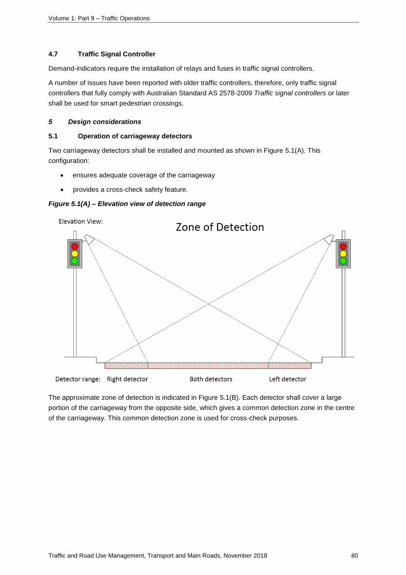
Volume 1: Part 9 – Traffic Operations
Traffic and Road Use Management, Transport and Main Roads, November 2018 80
4.7 Traffic Signal Controller
Demand-indicators require the installation of relays and fuses in traffic signal controllers.
A number of issues have been reported with older traffic controllers, therefore, only traffic signal
controllers that fully comply with Australian Standard AS 2578-2009 Traffic signal controllers or later
shall be used for smart pedestrian crossings.
5 Design considerations
5.1 Operation of carriageway detectors
Two carriageway detectors shall be installed and mounted as shown in Figure 5.1(A). This
configuration:
• ensures adequate coverage of the carriageway
• provides a cross-check safety feature.
Figure 5.1(A) – Elevation view of detection range
The approximate zone of detection is indicated in Figure 5.1(B). Each detector shall cover a large
portion of the carriageway from the opposite side, which gives a common detection zone in the centre
of the carriageway. This common detection zone is used for cross-check purposes.
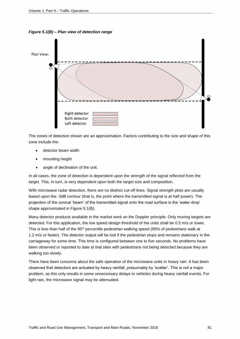
Volume 1: Part 9 – Traffic Operations
Traffic and Road Use Management, Transport and Main Roads, November 2018 81
Figure 5.1(B) – Plan view of detection range
The zones of detection shown are an approximation. Factors contributing to the size and shape of this
zone include the:
• detector beam width
• mounting height
• angle of declination of the unit.
In all cases, the zone of detection is dependent upon the strength of the signal reflected from the
target. This, in turn, is very dependent upon both the target size and composition.
With microwave radar detection, there are no distinct cut-off lines. Signal strength plots are usually
based upon the -3dB contour (that is, the point where the transmitted signal is at half power). The
projection of the conical ‘beam’ of the transmitted signal onto the road surface is the ‘water-drop’
shape approximated in Figure 5.1(B).
Many detector products available in the market work on the Doppler principle. Only moving targets are
detected. For this application, the low speed design threshold of the units shall be 0.5 m/s or lower.
This is less than half of the 95th percentile pedestrian walking speed (95% of pedestrians walk at
1.2 m/s or faster). The detector output will be lost if the pedestrian stops and remains stationary in the
carriageway for some time. This time is configured between one to five seconds. No problems have
been observed or reported to date at trial sites with pedestrians not being detected because they are
walking too slowly.
There have been concerns about the safe operation of the microwave units in heavy rain. It has been
observed that detectors are actuated by heavy rainfall, presumably by ‘scatter’. This is not a major
problem, as this only results in some unnecessary delays to vehicles during heavy rainfall events. For
light rain, the microwave signal may be attenuated.

Volume 1: Part 9 – Traffic Operations
Traffic and Road Use Management, Transport and Main Roads, November 2018 82
5.2 Selection guideline
Due to extra installation and maintenance costs, it is important to select appropriate locations for the
application of pedestrian detectors. Smart pedestrian crossings are recommended in the following
scenarios:
1. long pedestrian crossings (for example, over 4 lanes)
2. crossings with high traffic volume or high pedestrian volume
3. crossings with many mobility-impaired pedestrians, such as near hospitals, and
4. crossings used by bicycle riders.
Pedestrian detectors are not cost effective in the following scenarios:
Table 5.2 – Non-cost-effective scenarios for pedestrian detectors
Scenarios Carriageway Footpath
Vehicle volume or pedestrian volume is consistently low Not cost effective Not cost effective
Pedestrian phases run parallel with a major traffic movement
(Green time required for traffic is usually a lot longer than the pedestrians walk and clearance time)
Not cost effective Not cost effective
Very short crossing (for example, less than 6 meters) Not cost effective
There is low chance that the demand will be cancelled (for example, it’s unlikely for pedestrians to cross in a gap)
Not cost effective
5.3 Crossing distance
Recommendations are outlined in the Guide to Road Design – Part 4: Intersections and Crossing
Table 8.1 (Austroads 2009) to minimise crossing distances. Recommendations have the following
benefits:
1. greater travel time savings for pedestrians
2. improved pedestrian safety, through reducing their exposure to traffic
3. better coverage and lager common zone for carriageway detectors (refer to Clause 5.1)
4. reduction in required number of carriageway detector units.
Minimising the crossing distance can be achieved by building out the kerbs and narrowing traffic
lanes (refer to Figure 5.3 Minimise crossing distance). Pedestrian refuges shall not be used at
mid-block signalised crossing unless the crossing can be staggered and operated as two separate
crossings.
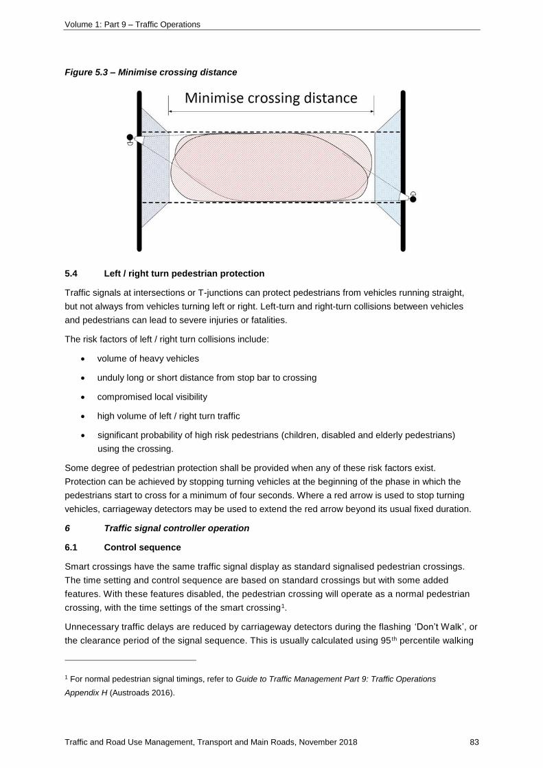
Volume 1: Part 9 – Traffic Operations
Traffic and Road Use Management, Transport and Main Roads, November 2018 83
Figure 5.3 – Minimise crossing distance
5.4 Left / right turn pedestrian protection
Traffic signals at intersections or T-junctions can protect pedestrians from vehicles running straight,
but not always from vehicles turning left or right. Left-turn and right-turn collisions between vehicles
and pedestrians can lead to severe injuries or fatalities.
The risk factors of left / right turn collisions include:
• volume of heavy vehicles
• unduly long or short distance from stop bar to crossing
• compromised local visibility
• high volume of left / right turn traffic
• significant probability of high risk pedestrians (children, disabled and elderly pedestrians)
using the crossing.
Some degree of pedestrian protection shall be provided when any of these risk factors exist.
Protection can be achieved by stopping turning vehicles at the beginning of the phase in which the
pedestrians start to cross for a minimum of four seconds. Where a red arrow is used to stop turning
vehicles, carriageway detectors may be used to extend the red arrow beyond its usual fixed duration.
6 Traffic signal controller operation
6.1 Control sequence
Smart crossings have the same traffic signal display as standard signalised pedestrian crossings.
The time setting and control sequence are based on standard crossings but with some added
features. With these features disabled, the pedestrian crossing will operate as a normal pedestrian
crossing, with the time settings of the smart crossing1.
Unnecessary traffic delays are reduced by carriageway detectors during the flashing ‘Don’t Walk’, or
the clearance period of the signal sequence. This is usually calculated using 95 th percentile walking
1 For normal pedestrian signal timings, refer to Guide to Traffic Management Part 9: Traffic Operations
Appendix H (Austroads 2016).
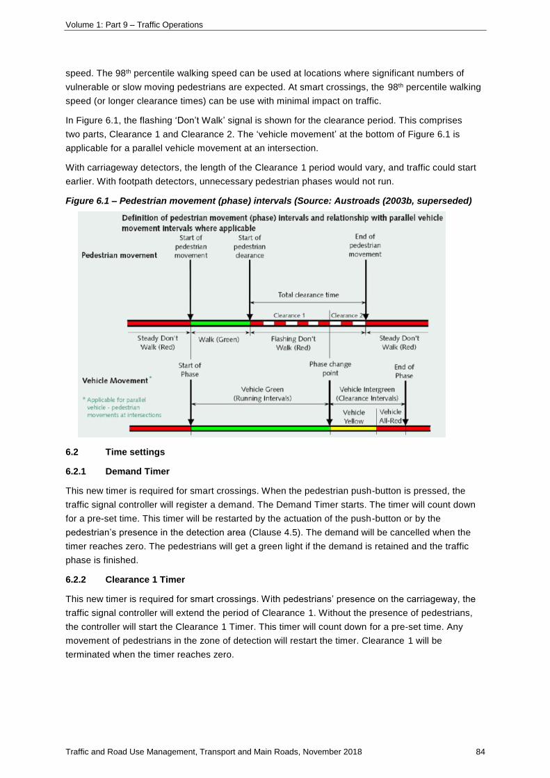
Volume 1: Part 9 – Traffic Operations
Traffic and Road Use Management, Transport and Main Roads, November 2018 84
speed. The 98th percentile walking speed can be used at locations where significant numbers of
vulnerable or slow moving pedestrians are expected. At smart crossings, the 98th percentile walking
speed (or longer clearance times) can be use with minimal impact on traffic.
In Figure 6.1, the flashing ‘Don’t Walk’ signal is shown for the clearance period. This comprises
two parts, Clearance 1 and Clearance 2. The ‘vehicle movement’ at the bottom of Figure 6.1 is
applicable for a parallel vehicle movement at an intersection.
With carriageway detectors, the length of the Clearance 1 period would vary, and traffic could start
earlier. With footpath detectors, unnecessary pedestrian phases would not run.
Figure 6.1 – Pedestrian movement (phase) intervals (Source: Austroads (2003b, superseded)
6.2 Time settings
6.2.1 Demand Timer
This new timer is required for smart crossings. When the pedestrian push-button is pressed, the
traffic signal controller will register a demand. The Demand Timer starts. The timer will count down
for a pre-set time. This timer will be restarted by the actuation of the push-button or by the
pedestrian’s presence in the detection area (Clause 4.5). The demand will be cancelled when the
timer reaches zero. The pedestrians will get a green light if the demand is retained and the traffic
phase is finished.
6.2.2 Clearance 1 Timer
This new timer is required for smart crossings. With pedestrians’ presence on the carriageway, the
traffic signal controller will extend the period of Clearance 1. Without the presence of pedestrians,
the controller will start the Clearance 1 Timer. This timer will count down for a pre-set time. Any
movement of pedestrians in the zone of detection will restart the timer. Clearance 1 will be
terminated when the timer reaches zero.
Volume 1: Part 9 – Traffic Operations
Traffic and Road Use Management, Transport and Main Roads, November 2018 85
6.2.3 Clearance 1 Maximum
Clearance 1 Maximum time is:
• the time Clearance 1 will run for, with the continuous detection of pedestrians on the
crossing or with the controller not in smart pedestrian mode
• total time calculated as per departmental standards for signalised pedestrian crossings,
using 1.0 m/s walking speed plus any additional time required for the special needs of
slower pedestrians (minus Clearance 2 time – see following).
The additional time should be site specific depending on the local environment and crossing width.
6.2.4 Clearance 2
Clearance 2 is the time period after Clearance 1 during which the ‘Don’t Walk’ signal continues to
flash.
At intersections, this is set equal to the yellow time of the phase that is losing right of way.
At mid-block pedestrian crossings, Clearance 2 should be set as low as possible to improve traffic
efficiency. With the current restriction, Clearance 2 and the yellow time may be set to three seconds.
Note that at a mid-block crossing, there is no traffic phase losing right of way at the end of the
pedestrian phase, but it is a limitation of some controller software that a minimum yellow time of
three seconds must be allowed for.
6.2.5 All-red interval
At mid-block pedestrian crossings, the all-red interval at the end of the pedestrian phase shall be set
to one second. Note that, at a mid-block crossing, the all red at the end of the pedestrian phase only
serves as an additional safety buffer in case there is someone still on the crossing after the
Clearance 2 and yellow periods. It is a limitation of some controller software that a minimum all red
time of one second must be allowed for, but this standard has been adopted as a reasonable safety
measure.
6.3 Smart crossing modes
The operation of smart crossing includes two smart crossing modes, which shall be implemented
independently.
Smart clearance mode
Smart clearance mode allows Clearance 1 timing to be varied. This mode requires carriageway
detectors.
Smart demand mode
Smart demand mode allows cancellation of unnecessary phase demand. This mode requires
footpath detectors.
Fall-back mode
Fall-back mode shall be available to run a smart crossing with standard timing and sequence.
When started, a smart crossing shall operate in fall-back mode. The associated smart crossing
mode shall be activated after three correct operations of carriageway detectors or footpath
detectors.
Volume 1: Part 9 – Traffic Operations
Traffic and Road Use Management, Transport and Main Roads, November 2018 86
If pedestrian detectors fail, the smart crossing modes are disabled. The traffic signal controller shall
reactivate the smart modes following three correct operations of the associated detectors.
6.4 Interaction with Traffic Management System
The traffic signal controllers shall:
• report pedestrian detector faults to the traffic management system (STREAMS)
• allow the traffic management system to disable the associated smart crossing modes.
This override feature is used to manually disable the smart crossings when:
• faulty pedestrian detectors are suspected, or
• fixed time operation is required to optimise traffic signal coordination.
6.5 Fault monitoring
Pedestrian detectors will normally fail-safe in the occupied / pedestrian present state. But at a smart
crossing, if one or more detectors does fail in the unoccupied state or is misaligned so that it does
not cover the required zone of detection. The crossing could run the minimum or a reduced
Clearance 1 time or cancel the pedestrian demand when a pedestrian is still present. At a
conventional pedestrian signalised crossing, a faulty push-button or a faulty pedestrian lantern will
cause a similar level of risk; however, additional error checking is provided at smart crossings.
Carriageway and footpath detectors are monitored in the traffic controller personality to detect errors
and switch the smart crossing to a fall-back mode. An early detection of detector faults will reduce
the likelihood of incorrect operation. A defective smart crossing will switch to fall-back mode and
minimise the consequence of detector faults; therefore, the risk is reduced to an acceptable level.
In rare events, even with these measures in place, it may take some time before a fault is detected
– possibly until reported by the public or discovered by routine inspection. The facility for the
TMC operator to switch the controller to fall back mode is thus required.
6.5.1 Carriageway detectors
The major risk with carriageway detectors is incorrect termination of the Clearance 1.
If the detector system fails in unoccupied state or if a detector is misaligned, traffic could be given a
green signal while pedestrians are still on the crossing. This is not a catastrophic failure as drivers
should not take the green signal as a cue to drive through pedestrian traffic. There is, however, a
risk that, if there is no traffic queued when traffic is given the green signal, a driver approaching
‘at speed’ could fail to see (and consequently collide with) a pedestrian still on the crossing.
Volume 1: Part 9 – Traffic Operations
Traffic and Road Use Management, Transport and Main Roads, November 2018 87
Measures to alleviate carriageway detector faults include the following:
• Overlapping the zones of detection provides some redundancy. If one detector fails or is
misaligned, only a relatively small area near the kerb will not be covered.
• The detectors are designed to be fail-safe. Should the detector fail, it provides a continuous
signal, as though pedestrians were continuously crossing. As a result, the clearance time is
extended to the maximum.
• The controller personality is modified to monitor the overlapping output of the detectors. This
checks when a detector is actuated during ‘walk’ or Clearance 1, an overlapping detection
from the other detector is received. This is not an absolute test as pedestrians will only be
detected by one detector if they walk on the extreme edge, or outside the marked pedestrian
crossing area. Thus one error shall be registered if only one detector is actuated during
‘walk’ or Clearance 1. An error shall be deleted if the overlapping actuation occurs. When
there are three errors, a detector fault shall be assumed. As a result, the controller will be
switched to fall-back mode.
6.5.2 Footpath detectors
The major risk with using footpath detectors is incorrect cancellation of pedestrian demands.
If a footpath detector does not detect the presence of a pedestrian, the demand will be cancelled. If
the pedestrians notice that the demand indicator has gone off, they can press and hold the
push-button to reinitiate and hold the demand. It is, however, possible that some pedestrians may
decide to risk crossing without the pedestrian phase.
Similar to carriageway detectors, cross-checks can be used for the fault monitoring of footpath
detectors. After a push-button is pressed, an actuation is expected from associated footpath
detectors within a short period of time (for example, three seconds). This is not an absolute test, as
push-buttons may sometimes be used inappropriately. One error shall be registered if no actuation
is seen within the time window. An error shall be deleted if the expected actuation occurs. When
there are three errors, a device fault shall be assumed. As a result, the controller shall be switched
to fall-back mode.
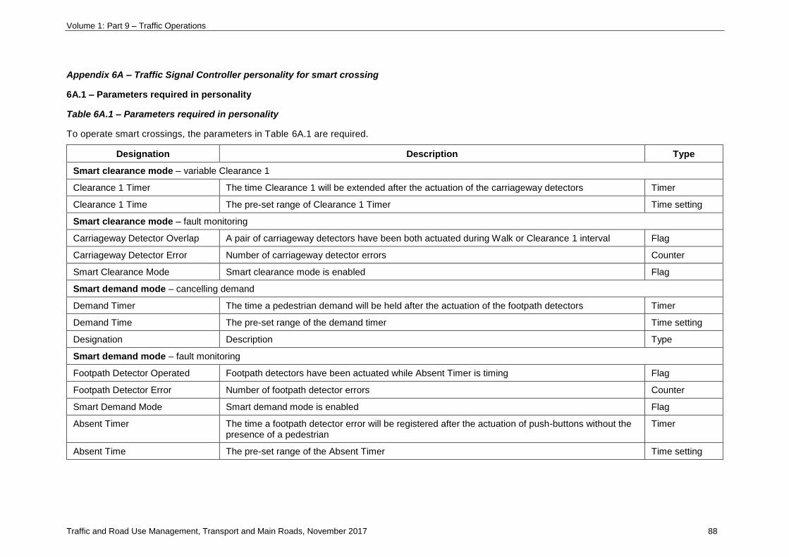
Volume 1: Part 9 – Traffic Operations
Traffic and Road Use Management, Transport and Main Roads, November 2017 88
Appendix 6A – Traffic Signal Controller personality for smart crossing
6A.1 – Parameters required in personality
Table 6A.1 – Parameters required in personality
To operate smart crossings, the parameters in Table 6A.1 are required.
Designation Description Type
Smart clearance mode – variable Clearance 1
Clearance 1 Timer The time Clearance 1 will be extended after the actuation of the carriageway detectors Timer
Clearance 1 Time The pre-set range of Clearance 1 Timer Time setting
Smart clearance mode – fault monitoring
Carriageway Detector Overlap A pair of carriageway detectors have been both actuated during Walk or Clearance 1 interval Flag
Carriageway Detector Error Number of carriageway detector errors Counter
Smart Clearance Mode Smart clearance mode is enabled Flag
Smart demand mode – cancelling demand
Demand Timer The time a pedestrian demand will be held after the actuation of the footpath detectors Timer
Demand Time The pre-set range of the demand timer Time setting
Designation Description Type
Smart demand mode – fault monitoring
Footpath Detector Operated Footpath detectors have been actuated while Absent Timer is timing Flag
Footpath Detector Error Number of footpath detector errors Counter
Smart Demand Mode Smart demand mode is enabled Flag
Absent Timer The time a footpath detector error will be registered after the actuation of push-buttons without the presence of a pedestrian
Timer
Absent Time The pre-set range of the Absent Timer Time setting
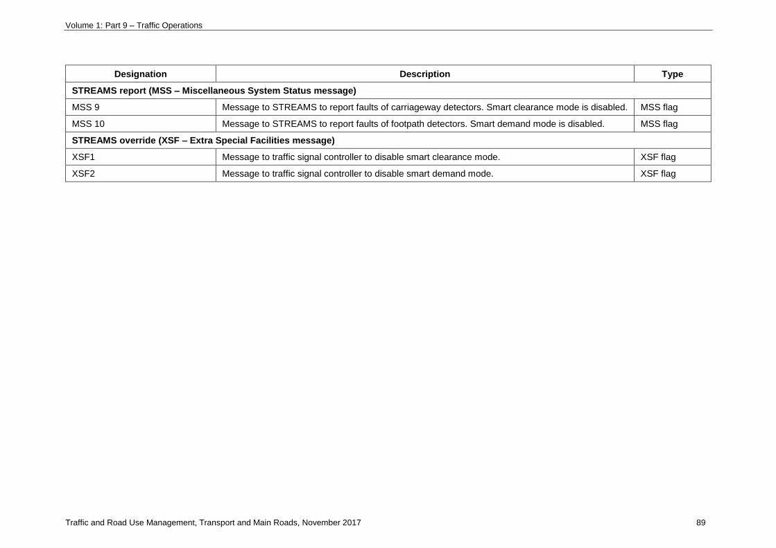
Volume 1: Part 9 – Traffic Operations
Traffic and Road Use Management, Transport and Main Roads, November 2017 89
Designation Description Type
STREAMS report (MSS – Miscellaneous System Status message)
MSS 9 Message to STREAMS to report faults of carriageway detectors. Smart clearance mode is disabled. MSS flag
MSS 10 Message to STREAMS to report faults of footpath detectors. Smart demand mode is disabled. MSS flag
STREAMS override (XSF – Extra Special Facilities message)
XSF1 Message to traffic signal controller to disable smart clearance mode. XSF flag
XSF2 Message to traffic signal controller to disable smart demand mode. XSF flag

Volume 1: Part 9 – Traffic Operations
Traffic and Road Use Management, Transport and Main Roads, November 2017 90
6A.2 – Smart Clearance Mode
6A.2.1 Clearance 1 Timer
When carriageway detectors are actuated, the controller will extend the Clearance 1. The
Clearance 1 Time is typically three seconds. Carriageway detectors have an internal lagging with
their outputs. This internal lagging should be reduced to a minimum if it is configurable. With
adequate risk assessment and public awareness of smart crossings, the Clearance 1 Time may be
reduced to one second to improve efficiency.
The Clearance 1 period is controlled by carriageway pedestrian detectors as follows:
• At the end of the walk period, reset and start the Clearance 1 Timer.
• Actuating either of the carriageway detectors will reset and start the Clearance 1 Timer.
• If the Clearance 1 Timer reaches zero and the Smart Clearance Mode Flag is TRUE, then
the Clearance 1 will be expired.
6A2.2 Smart Clearance Fault monitoring
When traffic signal controllers start:
• the Smart Clearance Mode Flag and the Carriageway Detectors Overlap Flag are set FALSE
• the Carriageway Detector Error is set to 3.
Carriageway detector faults are monitored as follows:
• During pedestrian walk or clearance time, and if both carriageway detectors are actuated
simultaneously, the controller will:
set the Carriageway Detectors Overlap Flag TRUE.
• After clearance periods, test the Carriageway Detector Overlap Flag as below:
If the Carriageway Detectors Overlap Flag is FALSE and the Carriageway Detector Error
is below 3, count up Carriageway Detector Error by 1.
If the Carriageway Detectors Overlap Flag is TRUE and the Carriageway Detector Error is
over 0, count down Carriageway Detector Error by 1.
If the Carriageway Detector Error reaches 3, then set the Smart Clearance Mode Flag to
FALSE.
If the Carriageway Detector Error reaches 0, then set the Smart Clearance Mode Flag to
TRUE.
After the Carriageway Detector Overlap Flag has been checked, set it back to FALSE.
6A.3 – Smart Demand Mode
6A.3.1 Demand Timer
With a registered demand, the controller will hold the demand when the footpath detectors are
actuated. The Demand Time is typically three seconds. Footpath detectors have a configurable
internal lagging (hold time) with their outputs. This internal lagging should be reduced to a minimum.

Volume 1: Part 9 – Traffic Operations
Traffic and Road Use Management, Transport and Main Roads, November 2017 91
The pedestrian demand is controlled by footpath pedestrian detectors as follows:
• The demand for the pedestrian movement is initiated by associated push buttons. The
Demand Timer will be started in the meantime.
• Either of the following situations will reset and start the Demand Timer:
Any associated footpath detector is actuated.
Any associated push-button is pressed.
• If the Demand Timer reaches zero and the Smart Demand Mode Flag is TRUE, then the
demand for the pedestrian movement will be cancelled.
6A.3.2 Smart Demand Fault Monitoring
When traffic signal controllers start:
• the Smart Demand Mode Flag and the Footpath Detectors Operated Flag are set FALSE
• the Footpath Detector Error is set to 3.
The Absent Time is typically three seconds. Footpath detector fault is monitored as follows:
• When a push--button is pressed, the associated Absent Timer starts.
When the Absent Timer is timing, any actuation from the associated footpath detectors will
set the Footpath Detector Operated Flag TRUE.
• After the Absent Timer expires, test the Footpath Detector Operated Flag as below:
If the Footpath Detector Operated Flag is FALSE and the Footpath Detector Error is below
3, count up the Carriageway Detector Error by 1.
If the Footpath Detector Operated Flag is TRUE and the Footpath Detector Error is over 0,
count down the Carriageway Detector Error by 1.
If the Footpath Detector Error reaches 3, then set the Smart Demand Mode Flag to
FALSE.
If the Footpath Detector Error reaches 0, then set the Smart Demand Mode Flag to TRUE.
After the Footpath Detector Operated Flag has been checked, set it back to FALSE.
6A.4 – STREAMS interaction
Four special messages are used to interact with STREAMS and facilitate the override and report
features.
6A.4.1 STREAMS Override
STREAMS shall have override control to disable the operation of smart crossing modes.
Two XSF (Extra Special Facilities) inputs at traffic signal controllers are used to receive overrides
from STREAMS.
If controller receives the XSF1 (TRUE), the Smart Clearance Mode Flag will be set FALSE.
If controller receives the XSF2 (TRUE), the Smart Demand Mode Flag will be set FALSE.

Volume 1: Part 9 – Traffic Operations
Traffic and Road Use Management, Transport and Main Roads, November 2017 92
6A.4.2 STREAMS Report
If any smart mode flag is set to FALSE, a message shall be sent to STREAMS to advise the
TMC (Traffic Management Centre) that pedestrian detectors are faulty. Two MSS (Miscellaneous
System Status) messages are used at traffic signal controllers to report faults to STREAMS.
If the Smart Clearance Mode Flag is FALSE and the XSF1 is FALSE, then the MSS9 is sent (set
TRUE) to STREAMS, otherwise set the MSS9 FALSE.
If the Smart Demand Mode Flag is FALSE and the XSF2 is FALSE, then the MSS10 is sent (set
TRUE) to STREAMS, otherwise set the MSS10 FALSE.
Volume 1: Part 9 – Traffic Operations
Traffic and Road Use Management, Transport and Main Roads, November 2018 93
Appendix 6B – Nearside lanterns (UK)
Nearside lanterns are not recommended for use in Queensland as:
• an extensive education campaign would be required to ensure that there is no confusion and
increased crash risk
• the legal status of the device requires clarification.
A UK puffin pedestrian crossing includes pedestrian detectors and nearside lanterns. Nearside
lanterns are designed to be located either above or integral with the push-button. Nearside lanterns
show a steady red-man instead of a flashing red-man during clearance time. Nearside lanterns have
the following potential benefits:
• improved compliance rate, by stopping pedestrians crossing during clearance time
• reduced traffic delay and improved safety, as there is better compliance during clearance time
• better visibility, as it is closer to pedestrians and easier to see, especially for vision-impaired
pedestrians
• reduced sun-phantom and wash-out effects
• easier to see the approaching vehicles and signals simultaneously
• reduced confusion by removing flashing red-man signal, and
• reduced angle of view to eliminate ‘see-through’ by drivers and other pedestrians looking at
wrong lanterns.

Volume 1: Part 9 – Traffic Operations
Traffic and Road Use Management, Transport and Main Roads, November 2018 94
6.4.3-6 Pedestrian countdown timers
This section defines recommended practice on the application of pedestrian countdown timer (PCT)
displays in Queensland and supplements guidance contained in the following Austroads publications:
• Austroads Guide to Traffic Management Part 6 Intersections, Interchanges and Crossings
• Austroads Guide to Traffic Management Part 9 Traffic Operations
• Austroads Guide to Traffic Management Part 10 Traffic Control and Communication Devices.
1 Background
‘Standard’ pedestrian signals at traffic signals and pedestrian actuated crossings provide a short green
WALK period for pedestrians to commence crossing followed by a clearance flashing red
DON’T WALK period of sufficient time to allow pedestrians to complete the crossing before a steady
red DON’T WALK period and a commencement of a conflicting vehicle green phase. Under this
operation the Queensland Road Rules permit pedestrians to commence crossing during the green
WALK period only.
While the standard sequence generally serves pedestrians well at most locations, an issue can arise
at locations with high pedestrian demand. At these sites, due to high pedestrian volumes, it is common
to see pedestrians start to walk and complete the crossing well within the relatively long clearance
flashing DON’T WALK period that is required to cater for the less able bodied pedestrians to complete
their crossing.
The PCT display provides information to pedestrians on remaining duration of the pedestrian
clearance phase. PCT safety and efficiency relies upon pedestrians being able to judge for
themselves, how much time they need to complete the crossing if they commence to cross during the
PCT sequence. PCTs appear to increase pedestrian amenity. There is currently limited evidence
regarding PCT safety benefits.
2 Applicability
PCTs can only be used where pedestrian clearance times are fixed and are most appropriate at
scramble crossings or mid-block crossings. Pedestrian responsive traffic signals incorporating
pedestrian detection technology (refer TRUM Volume 1 Guide to Traffic Management Part 9 Traffic
Operations Section 6.4.3-4 Two-aspect signal controls of pedestrian crossings on slip lanes) are
preferred over PCTs due to operational benefits realised for all road users. PCTs are incompatible for
use in conjunction with smart pedestrian crossings, as the clearance times vary based upon
pedestrian presence.
To maximise the benefit for pedestrians while providing an appropriate level of safety, the following
criteria should be considered for to determine whether PCTs are appropriate:
PCTs should only be installed at crossings where the countdown timer period is greater than
six seconds as providing PCTs at locations with short clearance times provides little or no real
crossing benefit for pedestrians.
PCTs are potentially most appropriate in areas with high pedestrian demand: for example, CBD,
shopping precincts, public transport hubs.
Volume 1: Part 9 – Traffic Operations
Traffic and Road Use Management, Transport and Main Roads, November 2018 95
In some cases, PCTs can result in increased delays for turning vehicles, as more pedestrians cross
during the clearance period. As a result, the impact on efficiency may need to be considered at
intersections with high volumes of turning vehicles.
PCTs should not be used at crossings predominantly used by primary school children – it is
considered that some school children may not be sufficiently well developed to estimate the distance
required for them to cross during the PCT or to understand the risk of crossing too late and continuing
to walk during the steady red DON’T WALK.
3 Operational issues
On controller ‘start up’, the PCT unit needs to learn the applicable clearance time. During the initial
cycle, the PCT will show a standard sequence flashing red DON’T WALK (symbol).
As much as possible, PCT displays should be shielded from the view of approaching drivers and
unintended pedestrian movements by lantern positioning or by the use of extended length visors.
4 Installation requirements
PCT displays shall be installed in accordance with requirements set out in MUTCD Part 14 Traffic
Signals.
Where PCT displays are installed, the G9-Q10-2 adhesive label shall be positioned above the top of
the pedestrian push-button. This label replaces the CROSS WITH CARE (G9-Q10) adhesive label
usually installed at signalised crossings.
Volume 1: Part 9 – Traffic Operations
Traffic and Road Use Management, Transport and Main Roads, November 2018 96
6.6 Traffic signal controllers
6.6-1 Controllers
The traffic signal controller is the equipment that switches power to the signal lanterns and controls the
duration and sequence of the lantern displays. Ground-mounted interlocked and solid-state controllers
are used with operations ‘burned into’ an EPROM (Erasable Programmable Read-Only Memory).
1 Location
Controllers must be located so access can be gained for maintenance purposes. A ground-mounted
controller has only one door for access. This type of controller is normally located adjacent to the
property boundary, with the door opening towards the footway. The location of the controller is also
affected by other conditions. Ideally, the controller should be located so that:
• a continuous 240 V single-phase power supply can be conveniently obtained (some poles
cater for roadway lighting or high voltage supply only)
• a Telstra line is available nearby for STREAMS communications
• it is clear of high-voltage poles and cabinets with electrodes or earth grids as this can affect
the electronics in the controller
• it is clear of future widening proposals
• the position does not detract significantly from the visual quality of the streetscape (painting in
a decorative way may be appropriate)
• there will be an unobstructed view of all approaches to the site for timing and maintenance
purposes
• it does not unduly obstruct the footway
• it will not be unduly exposed to accidental damage by passing traffic
• access is available for maintenance personnel to park a vehicle.
If it is located where it is vulnerable to traffic, it must be protected by appropriate safety barrier. It is
preferable to find a less vulnerable location and avoid introduction of another hazard (safety barrier).
2 Full actuated control
In a full actuated application, the controller operates on continuously variable cycle lengths. All phase
green times are determined by the number of vehicles detected on the various controlled approaches.
The characteristics of full actuated control are:
• detectors on all approaches
• each phase has pre-set minimum green interval to provide starting time for standing vehicles
• green interval is extended by pre-set passage time for each actuation after the minimum green
interval expires, provided a gap greater than the passage time does not occur
• green extension is limited by pre-set maximum limit
• yellow change and all-red intervals are pre-set for each phase
• each phase has a recall when both recalls are off, the green will remain on

Volume 1: Part 9 – Traffic Operations
Traffic and Road Use Management, Transport and Main Roads, November 2018 97
• one phase when no demand is indicated on the other phase – one recall is on; the green will
revert to that phase at every opportunity
both recalls are on; the controller will cycle on a fixed-time basis in the absence of
demand on either phase (one minimum green interval on each phase).
Volume 1: Part 9 – Traffic Operations
Traffic and Road Use Management, Transport and Main Roads, November 2018 98
6.7 Traffic detection
6.7.3 Detection system functions
6.7.3-1 Detector logic
Vehicles can be detected during two parts of the traffic signal cycle. Traffic waiting for a green signal
registers an initial demand that it requires right-of-way (call); provided advance detectors are no closer
than 15 m to the stop line, the controller can increment the initial green time. Traffic already given the
right-of-way via a green signal registers its continuing requirement for right-of-way so that the green
signal can be extended depending on the prevailing traffic conditions (extend).
Detector logic is used to specify the conditions, under which an actuation from a detector can call,
extend or increment a phase; for example, the standard detector logic for a stop line detector is:
• call a phase except while it is green
• extend a phase while it is green
and for an advance detector is:
• call a phase except while it is green
• extend a phase while it is green
• increment initial green except while it is green.
Using this logic, there is only one phase involved and only one condition for each function. This logic is
sufficient for a simple two-phase design but, for most other types of phasing, several conditions may
be required, and a detector may demand and/or extend more than one phase. When designing
detector logic for these situations, the basic aim is to minimise the cycle time while satisfying all the
traffic and safety needs of the intersection.
This is achieved by:
• avoiding the introduction of unnecessary phases by only registering and maintaining required
demands
• demanding a phase that satisfies the most (or main) vehicle movements
• minimising the variable initial green time by allowing detectors to increment when a queue is
forming
• avoiding unnecessary extension of a phase: for example, by ceasing extension by vehicles on
a given movement when that movement also runs in the following phase.

Volume 1: Part 9 – Traffic Operations
Traffic and Road Use Management, Transport and Main Roads, November 2018 99
7 Systems and procedures for arterial traffic control – other
7.2 Lane management systems
7.2.4 Tunnel control systems
7.2.4-1 Traffic management procedures for tunnel closures
The purpose of this supplement is to describe the traffic management practices to be used on the
approaches to a tunnel when the occurrence of an incident (planned or unplanned) requires full
closure of the tunnel carriageway.
The requirements of this supplement apply only to tunnel ramps that are located directly off a
motorway or freeway (that is, a high-flow, high-speed environment) or off arterials operating under
motorway / freeway conditions.
These practices, and the processes in which they are applied, are to be further articulated in the
incident management and subsequent traffic control plans for both planned and unplanned incidents
during the daily operation of the tunnel.
The full operational plan and risk assessments for the tunnel will be required to be developed
separately by each Tunnel Operator. The following requirements are to be considered as a minimum
only and each situation should be individually assessed to determine if any additional devices are
required. Planned closures will also necessitate additional traffic control devices in accordance with
the MUTCD Part 3 Works on Roads.
Table 7.2.4-1(A) – Abbreviations
Abbreviation Full title
CCTV Closed Circuit Television
CMS Changeable Message Sign
IPL In-pavement Lighting
LED Light Emitting Diode
MUTCD Manual of Uniform Traffic Control Devices
PA system Public Address system
MRTS (Transport and) Main Roads Technical Standards
TMC Traffic Management Centre
TRUM manual Traffic and Road Use Management manual
UPS Uninterruptible Power Supply
VMS Variable Message Sign
VSLS Variable Speed Limit Sign
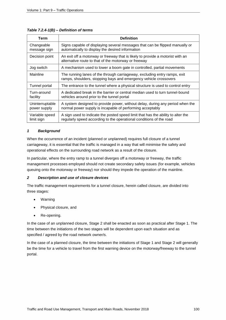
Volume 1: Part 9 – Traffic Operations
Traffic and Road Use Management, Transport and Main Roads, November 2018 100
Table 7.2.4-1(B) – Definition of terms
Term Definition
Changeable message sign
Signs capable of displaying several messages that can be flipped manually or automatically to display the desired information
Decision point An exit off a motorway or freeway that is likely to provide a motorist with an alternative route to that of the motorway or freeway
Jog switch A mechanism used to lower a boom gate in controlled, partial movements
Mainline The running lanes of the through carriageway, excluding entry ramps, exit ramps, shoulders, stopping bays and emergency vehicle crossovers
Tunnel portal The entrance to the tunnel where a physical structure is used to control entry
Turn-around facility
A dedicated break in the barrier or central median used to turn tunnel-bound vehicles around prior to the tunnel portal
Uninterruptable power supply
A system designed to provide power, without delay, during any period when the normal power supply is incapable of performing acceptably
Variable speed limit sign
A sign used to indicate the posted speed limit that has the ability to alter the regularly speed according to the operational conditions of the road
1 Background
When the occurrence of an incident (planned or unplanned) requires full closure of a tunnel
carriageway, it is essential that the traffic is managed in a way that will minimise the safety and
operational effects on the surrounding road network as a result of the closure.
In particular, where the entry ramp to a tunnel diverges off a motorway or freeway, the traffic
management processes employed should not create secondary safety issues (for example, vehicles
queuing onto the motorway or freeway) nor should they impede the operation of the mainline.
2 Description and use of closure devices
The traffic management requirements for a tunnel closure, herein called closure, are divided into
three stages:
• Warning
• Physical closure, and
• Re-opening.
In the case of an unplanned closure, Stage 2 shall be enacted as soon as practical after Stage 1. The
time between the initiations of the two stages will be dependent upon each situation and as
specified / agreed by the road network owner/s.
In the case of a planned closure, the time between the initiations of Stage 1 and Stage 2 will generally
be the time for a vehicle to travel from the first warning device on the motorway/freeway to the tunnel
portal.
Volume 1: Part 9 – Traffic Operations
Traffic and Road Use Management, Transport and Main Roads, November 2018 101
2.1 Stage 1 – Warning
Stage 1 consists of the following components:
a) variable message signs (VMS)
b) warning signs
c) LED in-pavement lights
d) variable speed limits signs
e) audible alarm, and
f) public address system.
These warning devices are located on the mainline, at the diverge, and on the ramp to the tunnel itself
and are to be activated simultaneously in the event of a closure. Refer to the Standard Drawings for a
comprehensive layout of these devices.
Variable message signs
As a minimum, a VMS is to be provided prior to the last decision point before the tunnel exit. This sign
is to be used to inform motorists of the closure and to encourage the use of alternative routes. A VMS
is to also be provided at the tunnel portal, directly above the entrance. In the event of a closure, this
VMS will display the text TUNNEL CLOSED / ALL VEHICLES STOP / WAIT FOR / EMERGENCY
SERVICES. All VMS shall comply with the requirements of the Austroads Guide to Traffic
Management, the MUTCD, and MRTS202 Variable Message Signs.
Warning signs
The following warning signs are to be provided both on the mainline and at the diverge:
a) Advance warning signs in the form of CMS are to be used in conjunction with any tunnel
advance static direction signs on the motorway, typically 1 km and 500 m prior to the exit. The
CMS panels are to be incorporated into the static direction signs such that the text TUNNEL
CLOSED can be displayed in the event of a closure (see Standard Drawings). Additionally,
two alternately-flashing yellow lights, each complying with the requirements of AS 2144, are to
be positioned on either side of the CMS panel and will be activated when the CMS displays
the closure message. All CMS shall comply with the requirements of the MUTCD and
MRTS227 Changeable Message Signs. The locations of all advance direction signs shall
comply with the requirements of the MUTCD.
b) Additionally, a flashing static warning sign is to be provided on the approach side of the
diverge from the motorway or freeway to the tunnel ramp. The sign is to display the text
TUNNEL CLOSED WHEN FLASHING, DO NOT EXIT. Two alternately-flashing yellow lights,
each complying with the requirements of AS 2144, are to be provided in both top corners of
the sign and will be activated in the event of a closure. The static sign shall comply with the
requirements of the MUTCD.
LED in-pavement lights
Red LED IPL is to be installed in the pavement along the full length of the continuity line at the diverge
from the motorway to the tunnel ramp. The lights shall have dimensions that comply with the
requirements of AS 1906.3. The lights are to be spaced in accordance with the MUTCD Part 2 Traffic
Volume 1: Part 9 – Traffic Operations
Traffic and Road Use Management, Transport and Main Roads, November 2018 102
Control Devices for General Use. The IPL will only be activated during the event of a closure, that is,
no IPL will be used during normal operating conditions. When activated, the IPL is to remain fully lit.
Variable speed limit signs
VSLS are to be provided on the tunnel ramp to reduce the speed in the event of a closure. The signs
shall be located as close to the diverge as possible while still being apparent to motorway traffic that
the speed applies to the ramp only. In the event of a closure, these signs shall reduce the ramp
regulatory speed limit. The maximum posted speed limit on the ramp during a closure shall be
60 km/hr. All VSLS shall comply with the requirements of the Austroads Guide to Traffic Management,
the MUTCD, and MRTS206 Provision of Variable Speed Limit and Lane Control Signs.
Audible alarm
An audible alarm is to be located at the tunnel portal to provide an audible warning of the closure
where pedestrian and/or cyclist use of the tunnel is permitted.
Public address system
A PA system shall be used at the tunnel portal where pedestrian and/or cyclist use of the tunnel is
permitted.
2.2 Stage 2 – Physical closure
A physical barrier must be installed to prevent traffic driving into the tunnel when the occurrence of an
incident requires full closure of the tunnel carriageway. The physical barrier must incorporate the
following components:
a) boom gate/s, and
b) dual-aspect traffic signals.
Where a turnaround facility is not provided within 200 m of the tunnel portal, the traffic management
measures for Stage 2 shall be duplicated just prior to the turnaround facility.
Stage 2 may be activated automatically after a predetermined period of time after the initiation of
Stage 1, or manually by an operator at the Tunnel TMC.
Traffic signals
Dual-aspect traffic signals are to be mounted and operated as follows:
a) For carriageways with two or more lanes, one set of signals is to be provided on each side of
the carriageway. For single-lane carriageways, one set of signals is to be provided on the
left-hand-side of the carriageway only.
b) Each set of signals must be mounted horizontally on the side of the carriageway, just prior to
the boom gate/s.
c) They shall be used in conjunction with an R6-6 STOP HERE ON RED SIGNAL sign.
d) Each set of signals must be housed in a single mounting enclosure and consist of dual red
aspects.
Volume 1: Part 9 – Traffic Operations
Traffic and Road Use Management, Transport and Main Roads, November 2018 103
e) When activated, the dual red aspect signals in each set must flash alternately with an
adjustable mark space ratio of 1.1:1, a cycle period of 1.1 seconds and must be adjustable in
the range 0.5 to 3.0 seconds in 0.1 second increments. The flash controller must provide an
overlap in ON time so that, at any instant in the cycle, at least one aspect is energised.
f) A white stop bar is to be painted on the pavement at the same physical location as the signals.
The signals must comply with the requirements of AS 2144, the MUTCD, and MRTS93 Traffic Signals.
All signs and pavement markings must comply with the requirements of the MUTCD.
Boom gate/s
A boom gate is to be provided at the tunnel portal. Where there are two or more lanes at the portal,
two boom gates are to be used with a maximum clearance of 2 m between booms. The boom gate/s
must incorporate the following features:
a) The boom arm is to move from a vertical to a horizontal position. When in the 'closure'
position, the boom gate is to always remain perpendicular to the traffic stream.
b) The boom arm is to be red-and-white striped and is to be fitted with high visual impact red
flashing lanterns that are activated when the boom gate arm starts to lower. The boom arm
design is to comply with the requirements of MUTCD Part 7 Railway Crossings.
c) There is to be a panelled section that extends from the boom gate arm to the road surface
when the gate is in the closure position.
d) The gates are to lower via a jog switch mechanism which allows the boom to be lowered in
partial movements to increase visibility.
e) There is breakaway of the boom gate arms at vehicle speeds of greater than 10 km/hr or
bends and distortion at lower-speed impacts.
The boom gate may be lowered automatically after some period of time after the initiation of the
flashing red signals or manually by an operator at the Tunnel TMC. Where pedestrian and/or cyclist
use of the tunnel is permitted, separate gates are to be provided on these paths.
2.3 Stage 3 – Re-opening
The re-opening procedure will be dependent upon each situation and shall be outlined in the tunnel's
operational plans. Generally, once all physical closure devices have been removed, warning devices
shall not be switched off until it is safe to do so as determined by the Tunnel Operator.
Volume 1: Part 9 – Traffic Operations
Traffic and Road Use Management, Transport and Main Roads, November 2018 104
3 Additional requirements
3.1 CCTV coverage
In addition to the requirements set out in the previous sections, full CCTV coverage of the following
areas is to be provided and shall be able to be viewed directly from both the Tunnel TMC and the
Transport and Main Roads' Regional TMC to allow manual assistance/intervention during a closure:
a) section/s of the mainline affected by the tunnel warning devices
b) the diverge from the mainline to the tunnel ramp
c) entire length of the tunnel ramp from the diverge to the tunnel portal
d) turnaround facility, and
e) tunnel portal.
3.2 Uninterruptible power supply
All traffic management systems and devices outlined in this supplement are considered by Transport
and Main Roads to be critical tunnel infrastructure. As such, these systems and devices shall be
backed up by a UPS system/s to allow full operation of all critical infrastructure (including
VMS display) for the greater of the time nominated by the Fire Engineering Design Brief and
two hours. The UPS may be fed by a diesel generator.
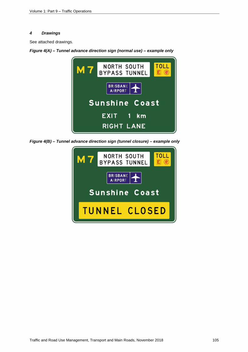
Volume 1: Part 9 – Traffic Operations
Traffic and Road Use Management, Transport and Main Roads, November 2018 105
4 Drawings
See attached drawings.
Figure 4(A) – Tunnel advance direction sign (normal use) – example only
Figure 4(B) – Tunnel advance direction sign (tunnel closure) – example only
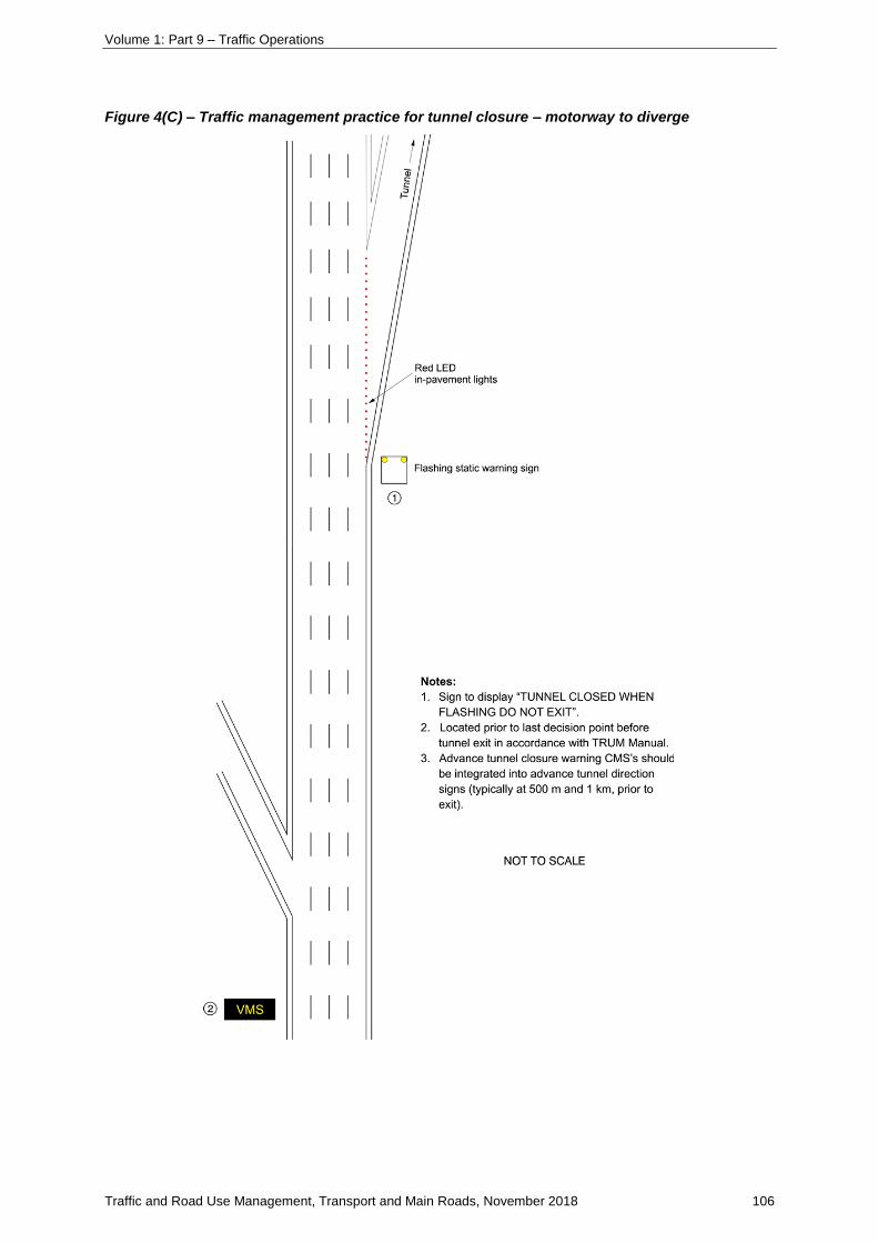
Volume 1: Part 9 – Traffic Operations
Traffic and Road Use Management, Transport and Main Roads, November 2018 106
Figure 4(C) – Traffic management practice for tunnel closure – motorway to diverge
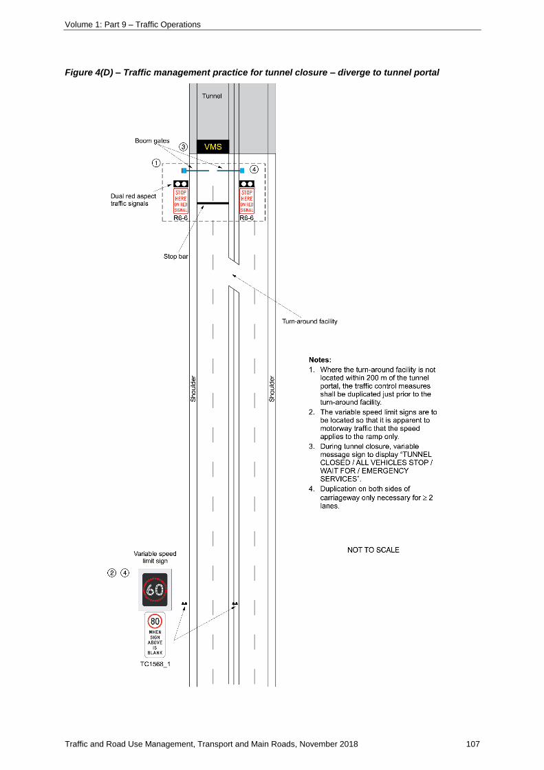
Volume 1: Part 9 – Traffic Operations
Traffic and Road Use Management, Transport and Main Roads, November 2018 107
Figure 4(D) – Traffic management practice for tunnel closure – diverge to tunnel portal
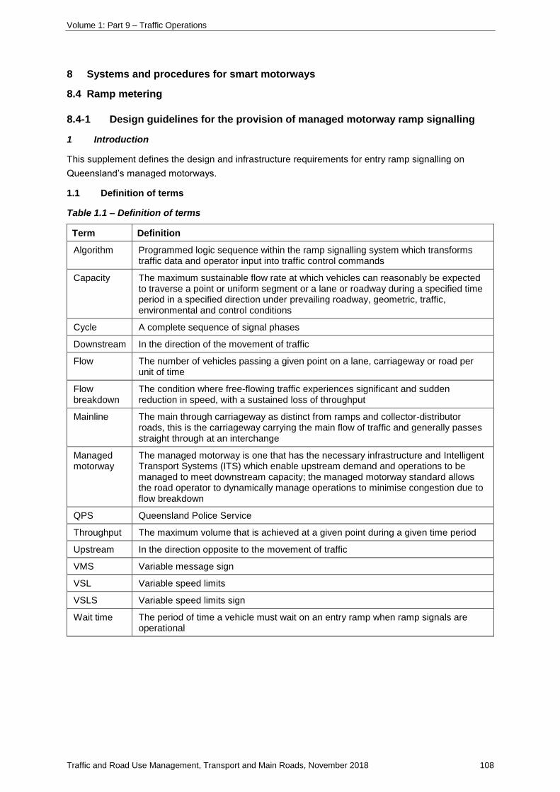
Volume 1: Part 9 – Traffic Operations
Traffic and Road Use Management, Transport and Main Roads, November 2018 108
8 Systems and procedures for smart motorways
8.4 Ramp metering
8.4-1 Design guidelines for the provision of managed motorway ramp signalling
1 Introduction
This supplement defines the design and infrastructure requirements for entry ramp signalling on
Queensland’s managed motorways.
1.1 Definition of terms
Table 1.1 – Definition of terms
Term Definition
Algorithm Programmed logic sequence within the ramp signalling system which transforms traffic data and operator input into traffic control commands
Capacity The maximum sustainable flow rate at which vehicles can reasonably be expected to traverse a point or uniform segment or a lane or roadway during a specified time period in a specified direction under prevailing roadway, geometric, traffic, environmental and control conditions
Cycle A complete sequence of signal phases
Downstream In the direction of the movement of traffic
Flow The number of vehicles passing a given point on a lane, carriageway or road per unit of time
Flow breakdown
The condition where free-flowing traffic experiences significant and sudden reduction in speed, with a sustained loss of throughput
Mainline The main through carriageway as distinct from ramps and collector-distributor roads, this is the carriageway carrying the main flow of traffic and generally passes straight through at an interchange
Managed motorway
The managed motorway is one that has the necessary infrastructure and Intelligent Transport Systems (ITS) which enable upstream demand and operations to be managed to meet downstream capacity; the managed motorway standard allows the road operator to dynamically manage operations to minimise congestion due to flow breakdown
QPS Queensland Police Service
Throughput The maximum volume that is achieved at a given point during a given time period
Upstream In the direction opposite to the movement of traffic
VMS Variable message sign
VSL Variable speed limits
VSLS Variable speed limits sign
Wait time The period of time a vehicle must wait on an entry ramp when ramp signals are operational
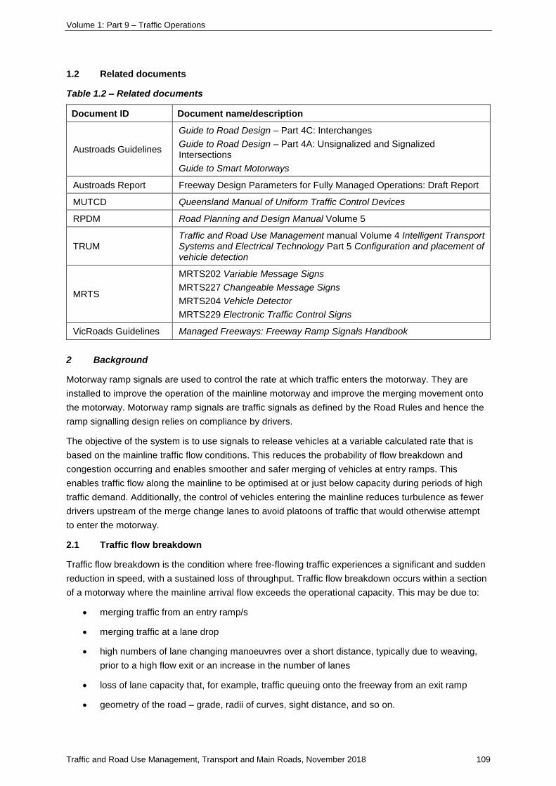
Volume 1: Part 9 – Traffic Operations
Traffic and Road Use Management, Transport and Main Roads, November 2018 109
1.2 Related documents
Table 1.2 – Related documents
Document ID Document name/description
Austroads Guidelines
Guide to Road Design – Part 4C: Interchanges
Guide to Road Design – Part 4A: Unsignalized and Signalized Intersections
Guide to Smart Motorways
Austroads Report Freeway Design Parameters for Fully Managed Operations: Draft Report
MUTCD Queensland Manual of Uniform Traffic Control Devices
RPDM Road Planning and Design Manual Volume 5
TRUM Traffic and Road Use Management manual Volume 4 Intelligent Transport Systems and Electrical Technology Part 5 Configuration and placement of vehicle detection
MRTS
MRTS202 Variable Message Signs
MRTS227 Changeable Message Signs
MRTS204 Vehicle Detector
MRTS229 Electronic Traffic Control Signs
VicRoads Guidelines Managed Freeways: Freeway Ramp Signals Handbook
2 Background
Motorway ramp signals are used to control the rate at which traffic enters the motorway. They are
installed to improve the operation of the mainline motorway and improve the merging movement onto
the motorway. Motorway ramp signals are traffic signals as defined by the Road Rules and hence the
ramp signalling design relies on compliance by drivers.
The objective of the system is to use signals to release vehicles at a variable calculated rate that is
based on the mainline traffic flow conditions. This reduces the probability of flow breakdown and
congestion occurring and enables smoother and safer merging of vehicles at entry ramps. This
enables traffic flow along the mainline to be optimised at or just below capacity during periods of high
traffic demand. Additionally, the control of vehicles entering the mainline reduces turbulence as fewer
drivers upstream of the merge change lanes to avoid platoons of traffic that would otherwise attempt
to enter the motorway.
2.1 Traffic flow breakdown
Traffic flow breakdown is the condition where free-flowing traffic experiences a significant and sudden
reduction in speed, with a sustained loss of throughput. Traffic flow breakdown occurs within a section
of a motorway where the mainline arrival flow exceeds the operational capacity. This may be due to:
• merging traffic from an entry ramp/s
• merging traffic at a lane drop
• high numbers of lane changing manoeuvres over a short distance, typically due to weaving,
prior to a high flow exit or an increase in the number of lanes
• loss of lane capacity that, for example, traffic queuing onto the freeway from an exit ramp
• geometry of the road – grade, radii of curves, sight distance, and so on.

Volume 1: Part 9 – Traffic Operations
Traffic and Road Use Management, Transport and Main Roads, November 2018 110
Flow breakdown may also be caused by factors which are unrelated to geometric layout and traffic
interaction such as an accident, weather, object or other incident on the carriageway.
When used within an active managed motorway system incorporating various traffic management
tools, managing the entering traffic with coordinated ramp signals is the most effective tool to assist in
managing flow to prevent (or delay) the onset of traffic flow breakdown on the mainline.
3 Ramp design
3.1 General
The key features of the motorway that are affected by the installation of ramp signals include:
1. ramp nose – the geometry and position of the ramp nose may affect the location of the
STOP line and ramp signal and subsequent provision of adequate acceleration length for
vehicles; reference to the ramp nose in this supplement refers to the physical ‘hard’ nose (not
the ‘soft’ nose defined by the pavement marking)
2. ramp width – the width of the ramp at the signals is determined by the number of lanes at the
STOP line required to serve the needs of ramp traffic (that is, for maximum ramp discharge
and a priority access (bypass) lane where a need has been identified); the width of the ramp is
critical for the provision of bypass lanes for priority vehicles, and
3. ramp and storage length – the ramp will be used for storing vehicles at the ramp signal. As
such, the length of the ramp and the number of lanes on the ramp determines the amount of
storage. The amount of storage on a ramp is related to the ramp flow and the system’s ability
to build a queue when flexibility is needed to vary cycle times to manage the mainline flow.
The specific requirements for these features on a managed motorway ramp design with ramp
signalling (new ramp or retrofitting of an existing ramp) shall comply with the following sections. The
design principles outlined are to ensure safe and efficient operation when the signals are operating as
well as when the signals are not operating.
The general principles are:
• provide operational safety:
when ramp signals are on; this is based on acceleration from a stationary position at the
STOP line to a speed that will provide suitable merging with the mainline traffic
when ramp signals are off; this is based on merging within the entire ramp to the ramp
nose prior to entering the mainline (for example, a two-lane to one-lane merge prior to the
ramp nose – that is, reverts to a standard on-ramp merge)
• maximise ramp storage for queuing vehicles to provide control of demand and ramp flow when
needed to manage the mainline flow
• maximise operational effectiveness to prevent flow breakdown on the mainline.
Where existing ramps of a higher geometric standard are being retrofitted with ramp signals – for
example, standards consistent with the Austroads Guide to Road Design – the ramp layout may be
modified to provide the managed motorway standard relating to storage and STOP line location for
merging prior to the ramp nose. This may require the shifting of the hard nose down the ramp to
achieve a STOP line to start of final merge taper, refer Figure 3.2.1 to meet the managed motorway
standard. This will help maximise the available ramp storage and minimise the effect of civil works.
Volume 1: Part 9 – Traffic Operations
Traffic and Road Use Management, Transport and Main Roads, November 2018 111
While longer distances for acceleration may be retained if the storage and STOP line location
standards meet the managed motorway requirements, consideration should be given to low-cost
solutions (for example, line marking) to achieve these geometrics.
The general layout and geometrics for managed motorway ramp signals for various entry ramp
configurations are indicated in the Transport and Main Roads Typical layouts in Appendix 8A.
3.2 STOP line location and acceleration length
The STOP line should be located to provide adequate merging and acceleration length while
maximising available storage length.
The acceleration length and merging distances downstream of the STOP line need to be satisfactory
to enable the entry ramp to function both when the signals are operational and when they are not.
It is noted that some existing ramps on the motorway network may have substandard layouts that do
not provide the required storage and acceleration capability. Designers should take all practical
measures to increase the ramp length and storage as well as ensure merging standards meet
required needs for acceleration and merging. Where practical, budgets for ramp signal retrofitting
projects on existing ramps should allow for the provision of additional ramp length and/or widening as
required.
Where the provision of additional ramp length or width to meet the managed motorway ramp
standards are not practical, designers should refer to the Austroads Guide to Road Design. Plans and
design exception documentation for entrance ramps in this category should be referred to the
Geospatial, Road Design and Capability Directorate, Transport and Main Roads for
review / acceptance.
3.2.1 Two-lane single-entry lane ramps (single-lane at ramp nose)
When determining the acceleration length and location of the STOP line, the design standards for
two-lane single-entry lane ramps (single lane at ramp nose) are based on the following principles:
• When ramp signals are off, the merging to a single-lane is to be completed prior to the ramp
nose at a design speed of 80 km/h. The two-lane to one-lane merge within the ramp is based
on an acceleration lane lateral movement merge rate of 1.0 m/s. These results in an 80 m
minimum merge length from the STOP line to the ramp nose.
Other provisions are:
▪ the motorway shoulder is fully developed at the ramp nose as a run-out area
▪ speed limit signs for the motorway entry are located after leaving the STOP line,
typically 20-40 metres upstream of the nose.
• When ramp signals are on, the design is based on the acceleration distance from the STOP
line to merging with the mainline traffic as follows:
adopt a mainline operating speed in the left lane of 10 km/h less than the operating speed,
that is, 90 km/h in a 100 km/h posted speed motorway (this is consistent with free-flow
operational data and operating speeds when ramp signals would be operating)
adopt a 10 km/h speed differential for merging relative to the motorway left lane operating
speed (that is, acceleration from zero to an 80 km/h merging speed in a 100 km/h posted
speed motorway).
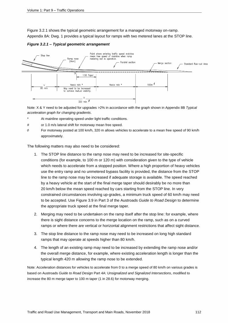
Volume 1: Part 9 – Traffic Operations
Traffic and Road Use Management, Transport and Main Roads, November 2018 112
Figure 3.2.1 shows the typical geometric arrangement for a managed motorway on-ramp.
Appendix 8A: Dwg. 1 provides a typical layout for ramps with two metered lanes at the STOP line.
Figure 3.2.1 – Typical geometric arrangement
Note: X & Y need to be adjusted for upgrades >2% in accordance with the graph shown in Appendix 8B Typical
acceleration graph for changing gradients.
* At mainline operating speed under light traffic conditions.
# or 1.0 m/s lateral shift for motorway mean free speed.
∅ For motorway posted at 100 km/h, 320 m allows vehicles to accelerate to a mean free speed of 90 km/h
approximately.
The following matters may also need to be considered:
1. The STOP line distance to the ramp nose may need to be increased for site-specific
conditions (for example, to 100 m or 120 m) with consideration given to the type of vehicle
which needs to accelerate from a stopped position. Where a high proportion of heavy vehicles
use the entry ramp and no unmetered bypass facility is provided, the distance from the STOP
line to the ramp nose may be increased if adequate storage is available. The speed reached
by a heavy vehicle at the start of the final merge taper should desirably be no more than
20 km/h below the mean speed reached by cars starting from the STOP line. In very
constrained circumstances involving up-grades, a minimum truck speed of 60 km/h may need
to be accepted. Use Figure 3.9 in Part 3 of the Austroads Guide to Road Design to determine
the appropriate truck speed at the final merge taper.
2. Merging may need to be undertaken on the ramp itself after the stop line: for example, where
there is sight distance concerns to the merge location on the ramp, such as on a curved
ramps or where there are vertical or horizontal alignment restrictions that affect sight distance.
3. The stop line distance to the ramp nose may need to be increased on long high standard
ramps that may operate at speeds higher than 80 km/h.
4. The length of an existing ramp may need to be increased by extending the ramp nose and/or
the overall merge distance, for example, where existing acceleration length is longer than the
typical length 420 m allowing the ramp nose to be extended.
Note: Acceleration distances for vehicles to accelerate from 0 to a merge speed of 80 km/h on various grades is
based on Austroads Guide to Road Design Part 4A: Unsignalized and Signalized Intersections, modified to
increase the 80 m merge taper to 100 m taper (1 in 28.6) for motorway merging.
Volume 1: Part 9 – Traffic Operations
Traffic and Road Use Management, Transport and Main Roads, November 2018 113
3.2.2 Three-lane ramps
Ramp layouts with three lanes at the STOP line require greater distances between the STOP line and
the nose for the merging movements, particularly if three lanes merge to a single lane at the nose.
When considering the operation of the ramp when the signals are on and off, the distance also varies
according to whether the third lane along the ramp is continuous (full-time use) or an auxiliary lane at
the STOP line (part-time use when the signals are on).
If two lanes are provided at the nose, that is, two-lane merge onto the motorway or a single-lane
merge plus an added lane, the merge distance for vehicles leaving the STOP line is similar to the
two-lane layout.
The typical layouts for ramps with three metered lanes at the STOP line are shown in Appendix 8A.
3.2.3 Four-lane ramps
Ramp layouts with four lanes at the STOP line require greater distances between the STOP line and
the nose for the merging movements. The layouts generally involve two, two-to-one lane merges
alongside each other so a distance of 120 m between the STOP line and ramp nose is desirable in
view of the complexity of the decision-making involved with a larger number of vehicles being released
at the same time.
The typical layouts for ramps with four metered lanes at the STOP line are shown in Appendix 8A.
3.2.4 Lane merging on the ramp
Where the number of lanes at the STOP line of the ramp signal exceeds the number of lanes merging
with the mainline motorway at the entry ramp merge, any merging of the stand-up lanes at the ramp
signals should be completed prior to the ramp nose (exception applies for non-signalised bypass
lanes, refer Section 3.3.1 for merge requirements).
For ramp layouts (including motorway-to-motorway interchanges), merge arrangements on the ramp
should use a zip merge (no line marking) to enable vehicles with faster acceleration to move ahead of
slower vehicles. Where a staggered STOP line is provided, a continuity line should be used to require
a lane change manoeuvre for the vehicle entering from the set-back STOP line. Merging into the left
lane of the motorway would then use a continuity line (lane change manoeuvre), with all vehicles
merging from the left.
Where there is a difference of two or more in the number of lanes at the ramp signals compared to at
the ramp nose, the merge should be designed so that:
• from three lanes to one lane, it may occur in sequential steps with a transition provided
between each subsequent merge, or simultaneously if a staggered STOP line is used – refer
Appendix 8A: Merge Layouts Motorway Ramp Signals 3 Lanes Dwg. 5.
• from four lanes to two lanes or one lane, two pairs of merges occur simultaneously. An
extended merge length of 120 metres shall be adopted to overcome any issues arising from
potential driver confusion due to an increased number of vehicles being released per signal
cycle – refer Appendix 8A: Merge Layouts Motorway Ramp Signals 4 Lanes Dwg. 6, and
• where bypass lanes are provided, refer to Section 3.3.1 for merge requirements.
Once the vehicles at the stand-up lanes of the ramp signals have merged into the lanes provided at
the ramp nose, a standard length of auxiliary lane and merge taper in accordance with Section 3.2.1.
See Appendix 8A for various configurations of merge layouts.
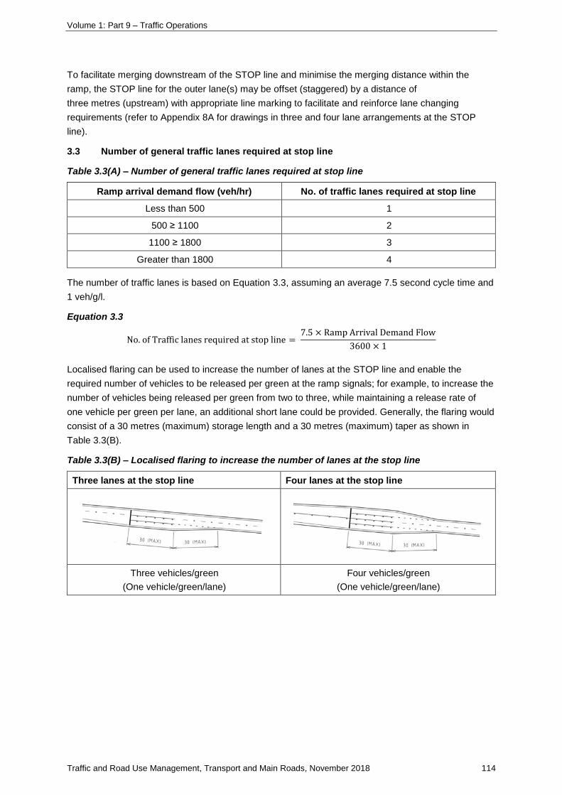
Volume 1: Part 9 – Traffic Operations
Traffic and Road Use Management, Transport and Main Roads, November 2018 114
To facilitate merging downstream of the STOP line and minimise the merging distance within the
ramp, the STOP line for the outer lane(s) may be offset (staggered) by a distance of
three metres (upstream) with appropriate line marking to facilitate and reinforce lane changing
requirements (refer to Appendix 8A for drawings in three and four lane arrangements at the STOP
line).
3.3 Number of general traffic lanes required at stop line
Table 3.3(A) – Number of general traffic lanes required at stop line
Ramp arrival demand flow (veh/hr) No. of traffic lanes required at stop line
Less than 500 1
500 ≥ 1100 2
1100 ≥ 1800 3
Greater than 1800 4
The number of traffic lanes is based on Equation 3.3, assuming an average 7.5 second cycle time and
1 veh/g/l.
Equation 3.3
No. of Traffic lanes required at stop line = 7.5 × Ramp Arrival Demand Flow
3600 × 1
Localised flaring can be used to increase the number of lanes at the STOP line and enable the
required number of vehicles to be released per green at the ramp signals; for example, to increase the
number of vehicles being released per green from two to three, while maintaining a release rate of
one vehicle per green per lane, an additional short lane could be provided. Generally, the flaring would
consist of a 30 metres (maximum) storage length and a 30 metres (maximum) taper as shown in
Table 3.3(B).
Table 3.3(B) – Localised flaring to increase the number of lanes at the stop line
Three lanes at the stop line Four lanes at the stop line
Three vehicles/green
(One vehicle/green/lane)
Four vehicles/green
(One vehicle/green/lane)
Volume 1: Part 9 – Traffic Operations
Traffic and Road Use Management, Transport and Main Roads, November 2018 115
Where two or more lanes are provided along an entry ramp, shoulders may not be required where
geometric constrictions are costly to design – for example, where resumptions and/or extensive
cut / fill earthworks or larger drainage structures might be needed to provide sufficient width to provide
a full width shoulder. This will generally enable:
• minimising of overall ramp and formation width
• retrofitting of existing ramps (with single-lane and shoulder) within the existing ramp width
without widening – kerb and channel may need to be constructed
• traffic signals to be located close to the edges of the ramp to facilitate drivers view of the
signals.
Where only one lane is provided at the STOP line, shoulders should be provided on the entry ramp to
ensure traffic flow can be maintained if a vehicle breaks down on the entry ramp.
Lane widths adopted should generally be consistent with lane widths required for non-signalised entry
ramps (that is, 3.5 m); however, where retrofitting of existing ramps is being implemented (for
example, replacing a single-lane and shoulder with two traffic lanes), narrow lane widths may be
acceptable to avoid minor widening (typically 3.2 m minimum).
3.3.1 Priority access (bypass) lanes
The need for priority access (bypass) lanes at the ramp signals may be considered at the design
stage, based on demand and the operational strategy for the motorway.
Bypass lanes are provided at motorway ramp signals to enable priority vehicles to bypass the general
traffic queues at the signals. Bypass lanes can be an effective method of providing priority (in the form
of a queue jump lane) to specific vehicles without designating lane space on the motorway mainline.
Generally, priority access lanes involve greater cost and should only be provided if there is a strategic
need: for example, the ramp services an industrial area.
Priority access lanes may be provided for:
• heavy vehicles in recognition of their economic importance, or
• public transport and high occupancy vehicles (typically T2) to provide an incentive for people
to use public transport or to share vehicles.
Lane widths adopted for bypass lanes should be consistent with lane widths required for
non-signalised entry ramps.
A delineated clearance zone, minimum of 0.7 m, between the general purpose lane/s and bypass lane
shall be provided to overcome potential safety issues associated with moving bypass vehicles passing
stationary general traffic. This delineation will also assist in defining the bypass lane.
The types of bypass lanes include: See Appendix 8A, Dwgs 2 and 3 for examples of bypass lanes.
Preference should be given to providing metered priority access lanes or partially-controlled bypass
lanes rather than full-time free-flow access. This improves motorway control and maximises the
potential for sustaining acceptable motorway performance.
Volume 1: Part 9 – Traffic Operations
Traffic and Road Use Management, Transport and Main Roads, November 2018 116
Generally, storage for general traffic should not be compromised when providing a priority access
lane. Where bypass lanes are to be provided, the following design guidelines shall be followed to
ensure bypassing vehicles are able to safely merge with other vehicles on the entry ramp and with the
mainline motorway traffic:
• Controlled bypass lanes – where more than one general purpose lane is provided, merging of
the general purpose traffic should occur prior to the bypass vehicles merging with general
purpose vehicles. Entry ramp traffic shall then merge with the mainline motorway traffic
excluding add lane designs. Where the bypass lane is controlled, the ability to close the lane
during periods when the ramp signals are not in operation needs to be considered, and
• partially controlled / free-flow bypass lanes – merging of the bypass vehicles with the general
traffic should occur over an extended length by means of an auxiliary lane as the speed of the
bypassing vehicle may be high and the speed differential between the controlled and
uncontrolled vehicles may also be high. As such, partially-controlled / free-flow bypass lanes
require additional pavement for an extended length in comparison to controlled bypass lanes.
The merging of general entry ramp vehicles and the bypass vehicles to the mainline motorway
should be undertaken in steps with a transition provided between each merge.
3.4 Total storage requirements
Provision of adequate storage is critical to the effective operation of ramp signals. The total length of
storage on a ramp is the sum of the storage of each lane for the length along the ramp between the
ramp signal stop line and the arterial road intersection. The total storage length could also include
dedicated left or right turns from the arterial road intersection.
The desired total storage (LrDes) to adequately store vehicles can be calculated from Equation 3.4:
Equation 3.4
𝐿𝑟𝐷𝑒𝑠 =𝑡𝑚𝑎𝑥−𝑤𝑎𝑖𝑡 × 𝑞𝑟𝑎 × 𝐿𝑣𝑠
60
LrDes = desired total storage in metres
tmax-wait = maximum wait time permitted in minutes
Lvs = storage space required to store an average vehicle – this depends
on the traffic characteristics of the site and the average vehicle
using the ramp, but 8.5 m could generally be adopted for a car
qra = peak ramp arrival demand flow in vehicles per hour.
The wait time considered reasonable for ramp signal design is four minutes. It is desirable that the
designer attempts to maximise storage to a six-minute wait time but it is recognised that this may not
be achievable on existing on-ramps connecting to the arterial network.
In locations where modifying the ramp to provide the desirable storage (four-minute wait time between
the ramp entrance and the ramp signals stop line) is not feasible, a lower storage value may need to
be considered. In these situations, typically a minimum three-minute wait time queue length (25%
reduction compared with the desirable) may need to be adopted for design. This amount of storage
will generally be sufficient to accommodate storage for turning vehicles arriving in a platoon from the
arterial road / ramp intersection signals; however, it would restrict the system’s ability to build a queue
in order to manage mainline traffic.
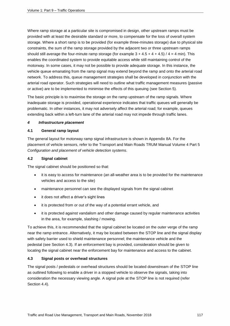
Volume 1: Part 9 – Traffic Operations
Traffic and Road Use Management, Transport and Main Roads, November 2018 117
Where ramp storage at a particular site is compromised in design, other upstream ramps must be
provided with at least the desirable standard or more, to compensate for the loss of overall system
storage. Where a short ramp is to be provided (for example three-minutes storage) due to physical site
constraints, the sum of the ramp storage provided by the adjacent two or three upstream ramps
should still average the four-minute ramp storage (for example 3 + 4.5 + 4 + 4.5) / 4 = 4 min). This
enables the coordinated system to provide equitable access while still maintaining control of the
motorway. In some cases, it may not be possible to provide adequate storage. In this instance, the
vehicle queue emanating from the ramp signal may extend beyond the ramp and onto the arterial road
network. To address this, queue management strategies shall be developed in conjunction with the
arterial road operator. Such strategies will need to outline what traffic management measures (passive
or active) are to be implemented to minimise the effects of this queuing (see Section 5).
The basic principle is to maximise the storage on the ramp upstream of the ramp signals. Where
inadequate storage is provided, operational experience indicates that traffic queues will generally be
problematic. In other instances, it may not adversely affect the arterial road; for example, queues
extending back within a left-turn lane of the arterial road may not impede through traffic lanes.
4 Infrastructure placement
4.1 General ramp layout
The general layout for motorway ramp signal infrastructure is shown in Appendix 8A. For the
placement of vehicle sensors, refer to the Transport and Main Roads TRUM Manual Volume 4 Part 5
Configuration and placement of vehicle detection systems.
4.2 Signal cabinet
The signal cabinet should be positioned so that:
• it is easy to access for maintenance (an all-weather area is to be provided for the maintenance
vehicles and access to the site)
• maintenance personnel can see the displayed signals from the signal cabinet
• it does not affect a driver’s sight lines
• it is protected from or out of the way of a potential errant vehicle, and
• it is protected against vandalism and other damage caused by regular maintenance activities
in the area, for example, slashing / mowing.
To achieve this, it is recommended that the signal cabinet be located on the outer verge of the ramp
near the ramp entrance. Alternatively, it may be located between the STOP line and the signal display
with safety barrier used to shield maintenance personnel; the maintenance vehicle and the
pedestal (see Section 4.3). If an enforcement bay is provided, consideration should be given to
locating the signal cabinet near the enforcement bay for maintenance and access to the cabinet.
4.3 Signal posts or overhead structures
The signal posts / pedestals or overhead structures should be located downstream of the STOP line
as outlined following to enable a driver in a stopped vehicle to observe the signals, taking into
consideration the necessary viewing angle. A signal pole at the STOP line is not required (refer
Section 4.4).
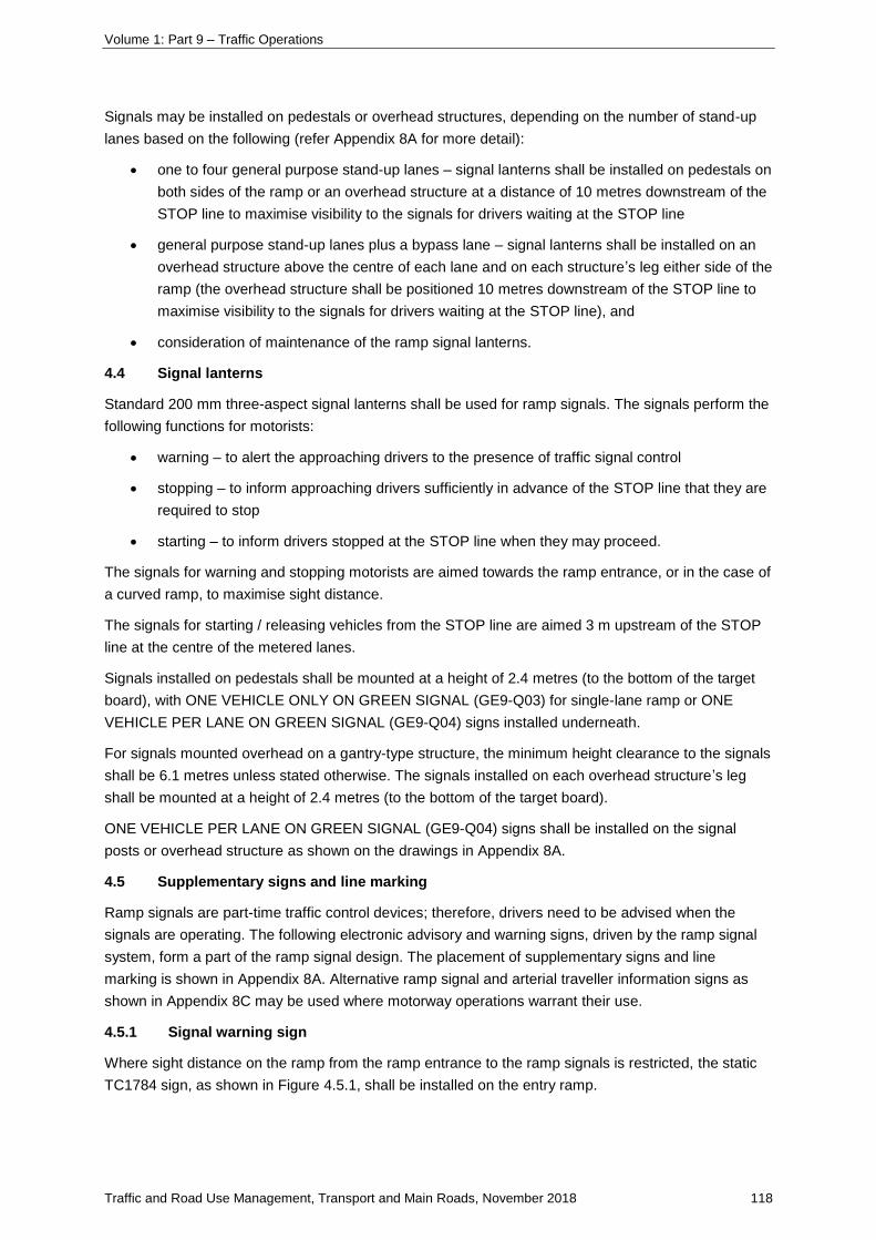
Volume 1: Part 9 – Traffic Operations
Traffic and Road Use Management, Transport and Main Roads, November 2018 118
Signals may be installed on pedestals or overhead structures, depending on the number of stand-up
lanes based on the following (refer Appendix 8A for more detail):
• one to four general purpose stand-up lanes – signal lanterns shall be installed on pedestals on
both sides of the ramp or an overhead structure at a distance of 10 metres downstream of the
STOP line to maximise visibility to the signals for drivers waiting at the STOP line
• general purpose stand-up lanes plus a bypass lane – signal lanterns shall be installed on an
overhead structure above the centre of each lane and on each structure’s leg either side of the
ramp (the overhead structure shall be positioned 10 metres downstream of the STOP line to
maximise visibility to the signals for drivers waiting at the STOP line), and
• consideration of maintenance of the ramp signal lanterns.
4.4 Signal lanterns
Standard 200 mm three-aspect signal lanterns shall be used for ramp signals. The signals perform the
following functions for motorists:
• warning – to alert the approaching drivers to the presence of traffic signal control
• stopping – to inform approaching drivers sufficiently in advance of the STOP line that they are
required to stop
• starting – to inform drivers stopped at the STOP line when they may proceed.
The signals for warning and stopping motorists are aimed towards the ramp entrance, or in the case of
a curved ramp, to maximise sight distance.
The signals for starting / releasing vehicles from the STOP line are aimed 3 m upstream of the STOP
line at the centre of the metered lanes.
Signals installed on pedestals shall be mounted at a height of 2.4 metres (to the bottom of the target
board), with ONE VEHICLE ONLY ON GREEN SIGNAL (GE9-Q03) for single-lane ramp or ONE
VEHICLE PER LANE ON GREEN SIGNAL (GE9-Q04) signs installed underneath.
For signals mounted overhead on a gantry-type structure, the minimum height clearance to the signals
shall be 6.1 metres unless stated otherwise. The signals installed on each overhead structure’s leg
shall be mounted at a height of 2.4 metres (to the bottom of the target board).
ONE VEHICLE PER LANE ON GREEN SIGNAL (GE9-Q04) signs shall be installed on the signal
posts or overhead structure as shown on the drawings in Appendix 8A.
4.5 Supplementary signs and line marking
Ramp signals are part-time traffic control devices; therefore, drivers need to be advised when the
signals are operating. The following electronic advisory and warning signs, driven by the ramp signal
system, form a part of the ramp signal design. The placement of supplementary signs and line
marking is shown in Appendix 8A. Alternative ramp signal and arterial traveller information signs as
shown in Appendix 8C may be used where motorway operations warrant their use.
4.5.1 Signal warning sign
Where sight distance on the ramp from the ramp entrance to the ramp signals is restricted, the static
TC1784 sign, as shown in Figure 4.5.1, shall be installed on the entry ramp.
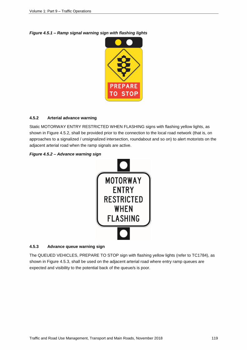
Volume 1: Part 9 – Traffic Operations
Traffic and Road Use Management, Transport and Main Roads, November 2018 119
Figure 4.5.1 – Ramp signal warning sign with flashing lights
4.5.2 Arterial advance warning
Static MOTORWAY ENTRY RESTRICTED WHEN FLASHING signs with flashing yellow lights, as
shown in Figure 4.5.2, shall be provided prior to the connection to the local road network (that is, on
approaches to a signalized / unsignalized intersection, roundabout and so on) to alert motorists on the
adjacent arterial road when the ramp signals are active.
Figure 4.5.2 – Advance warning sign
4.5.3 Advance queue warning sign
The QUEUED VEHICLES, PREPARE TO STOP sign with flashing yellow lights (refer to TC1784), as
shown in Figure 4.5.3, shall be used on the adjacent arterial road where entry ramp queues are
expected and visibility to the potential back of the queue/s is poor.
Volume 1: Part 9 – Traffic Operations
Traffic and Road Use Management, Transport and Main Roads, November 2018 120
Figure 4.5.3 – Advance queue warning sign
4.5.4 Other signs
Other static signs that shall be included as a part of the ramp signals installation are shown in
Appendix 8A. Care should be taken to separate signage according to the requirements of the MUTCD.
4.5.5 Line marking
The line marking and retroreflective pavement marking (RRPM) associated with the ramp signalling
designs as shown in Appendix 8A shall be provided in accordance with the MUTCD and the following
principles:
• longitudinal line marking shall include a 30-metre continuous lane line on the approach to the
stop line.
• edge lines are to be provided on both sides of the ramp – downstream of the STOP line, the
left edge line provides guidance for merging traffic
• continuity lines shall be used to indicate a lane diverge (increase in the number of lanes)
upstream of the STOP line
• where bypass lanes are provided, a delineated clearance zone of at least 0.7 metres shall be
provided between the bypass lane/s and general purpose lane/s
• the two-to-one-lane merging downstream of the STOP line shall be a zip merge, with line
marking from the STOP line to the FORM 1 LANE sign
• the merging downstream of a lane with a staggered STOP line shall be provided through the
use of a continuity line
• the STOP line shall be located 10 metres upstream of traffic signals (for pedestals and
overhead on gantries), and
• pavement marking shall be provided for any priority vehicles.
4.6 Variable speed limit signs
Where the motorway is operating under variable speed limits (VSL), pole-mounted variable speed limit
signs (VSLS) are provided on the entry ramp to inform entry ramp traffic of the prevailing speed on the
motorway to which they are entering.
Volume 1: Part 9 – Traffic Operations
Traffic and Road Use Management, Transport and Main Roads, November 2018 121
On entry ramps where a ramp signalling system is to be installed, the VSLS shall be located
downstream of the ramp signal but prior to the ramp nose. The location of the VSLS should provide
vehicles entering the motorway with sufficient acceleration distance to merge with mainline traffic both
when the ramp signals are operational and when they are not.
4.7 Closed circuit television
The provision of closed circuit television (CCTV) cameras with pan, tilt and zoom capability shall be
included in the ramp design to ensure full coverage of arterial road approaches, areas of the arterial
network expected to store ramp traffic, the length of the ramp and the motorway merge.
5 Managing ramp queue overflows
5.1 Entry ramp queues
In managing motorway access, the principal consideration is safety by way of preventing flow
breakdown and optimising efficiency and reliability on the motorway; therefore, the motorway capacity
is the main factor determining the ramp entry flows, rather than the traffic demands on the ramps
themselves.
Ideally, ramps should be designed to accommodate queues as described in Section 3.4. The ramp
queues should then be managed within the ramp length; however, at locations where high entry ramp
demands cannot be satisfied (it may not always be feasible to increase ramp storage), the traffic
queues may extend onto the arterial road network. In this situation, the additional storage length
required should be provided in such a way as to avoid interference with arterial road flows.
Where queues are expected to extend onto the arterial road on a regular basis, the designer shall
provide for detection of queues on the arterial road and include provisions to accommodate any queue
overflows. Several strategies that may aid to address the implications of these overflows on the
arterial road network are listed following. These are examples only and site-specific queue
management strategies will need to be developed in conjunction with the arterial road operator for
each entry ramp.
• Queuing traffic should be separated from local traffic where possible. In some places,
additional lanes may need to be provided on the arterial network to separate queuing traffic
from local traffic.
• In situations where queuing traffic to ramp signals approaches from multiple origins, queues
might extend back onto a number of local routes. Separation should be maintained on all
routes expected to experience queuing.
• In places where the ramp storage requirement is expected to extend back through
intersections on the arterial network, options to address end of queue issues should be
considered.
• Where queues extend through signalised intersections or roundabouts, pavement marking
and signage should inform motorists not to queue through the intersection. It may be
necessary to signalise the intersection, particularly if queued vehicles create obstructions to
visibility for drivers selecting a gap in the traffic stream/s. Where queues extend past property
accesses, consideration should be given to left-in, left-out-only movements.
• Unsignalized pedestrian crossings shall not be provided on routes expected to experience
queuing.

Volume 1: Part 9 – Traffic Operations
Traffic and Road Use Management, Transport and Main Roads, November 2018 122
• Where applicable, signal timings shall be optimised on the upstream signalised intersection to
ensure the length of the platoon arriving at the ramp signal each cycle does not exceed the
available storage.
• Shared lanes, for example, general traffic and bicycle lanes, may result in conflict points
where cyclist movements need to cross ramp traffic and shall be avoided on routes expected
to experience queuing.
• Buses and bus stops should remain separate from ramp queues.
• It is desirable that queues on the local network do not queue past accesses. Accesses to the
arterial road network should be controlled in locations where ramp queues are expected.
• Consideration should be given to the use of line marking, for example, a single continuous
line, to separate queuing traffic from ramp queues in order to discourage queue jumping.
Where ramp signalling is specified as part of a new motorway, motorway upgrade or as a singular
implementation, funding for the ramp signalling scheme must consider the changes required to the
local road network in order to manage queue overflows. The ability to store vehicles in such a manner
that reduces the implications on the local road network is imperative in the success of the ramp
signalling scheme and hence performance of the motorway.
5.2 Exit ramp queues
Traffic flow on the motorway may also be disrupted when queues on an exit ramp extend back to
block the left lane of the motorway or cause traffic to slow down prior to exiting. This may result in flow
breakdown under certain conditions and has significant safety implications for both mainline and exit
ramp traffic. Queuing from the exit ramp back onto the motorway may be a result of:
• inadequate intersection capacity at the arterial road intersection
• inadequate lane capacity on the ramp approaching the intersection
• insufficient ramp length, or
• inappropriate signal timings.
The following strategies may need to be considered in order to reduce the likelihood of exit ramp traffic
queuing back onto the motorway:
• provision of queue detectors near the exit ramp nose to detect queues extending beyond the
ramp length
• modification of arterial road traffic signal phase times to provide an increase in exit ramp traffic
discharge
• provision of a left-turn slip lane at the signals to reduce exiting delays
• increase the ramp storage capacity at the intersection (length or number of lanes)
• increase the ramp length
• where a roundabout provides the connection to the local road network, traffic control devices
may need to be installed to enable exit ramp queues to enter the roundabout, and
• allow exiting vehicles to queue on the shoulder lane of the motorway. Adequate signs and line
marking, and additional mainline upstream active signs need to be provided to outline the
control for this scenario.
Volume 1: Part 9 – Traffic Operations
Traffic and Road Use Management, Transport and Main Roads, November 2018 123
Where ramp signalling is specified as part of a new motorway, motorway upgrade or as a singular
implementation, funding for the ramp signalling scheme must consider the changes required to the
arterial / local road intersection or the exit ramp in order to manage queue overflows. The ability to
store vehicles on the exit ramps in such a manner that reduces the effects on the motorway mainline
is imperative for the success of the ramp signalling scheme and hence performance of the motorway.
6 Management of motorway to motorway interchanges
Motorway-to-motorway ramps provide connections between high-speed facilities where drivers may
not expect to stop or encounter a queue of stopped vehicles. Generally, these ramps are high traffic
flow environments where it is desirable to provide an uninterrupted motorway journey.
Signalling the upstream arterial road entry ramps to the motorways, rather than
motorway-to-motorway ramps, is the preferred initial strategy for managing the motorway-to-motorway
merge and downstream section of motorway; however, while this management strategy may be
successful where motorways join or merge together, it is unlikely to be effective where motorways
meet using motorway-to-motorway on ramps, as the upstream ramps will generally not provide
adequate flow conditions for managed motorway merging.
As a general principle, all flows entering a managed motorway should be controlled to enable
downstream mainline flow to be managed. Where the intersecting motorway does not have upstream
entry ramp signals or where the upstream ramp signalling is unable to provide the necessary
management of entering flows, signalling the motorway-to-motorway ramp may be required.
Additionally, signalling of motorway-to-motorway ramps may also assist in the ability to manage traffic
during incidents and improve the recovery from flow breakdown following an incident.
To improve safety associated with signalling high-speed motorway-to-motorway ramps, a TC1784 sign
is to be located on the ramp at a point prior to the estimated back of queue (subject to sight distance
requirements). The sign is to be activated when ramp signalling is operational to provide advance
warning to motorists. For long ramps, two or more TC1784 signs may be needed. These would be
staggered on each side of the ramp if the ramp has two lanes.
Additionally, a VSLS at the start of the exit ramp from the departing motorway is to be used to reduce
the speed to a maximum of 70 km/h when ramp signalling is operational. Repeater VSL signs may be
needed for a long ramp. In circumstances where it is desirable to further reduce the speed on the
ramp (for safety reasons), the VSLS may be used to do this, regardless of the posted speed limit on
the departing motorway at that time.
Volume 1: Part 9 – Traffic Operations
Traffic and Road Use Management, Transport and Main Roads, November 2018 124
Appendix 8A –Typical layouts
NOTE: The general layout and design for managed motorway ramp signals for various entry ramp configurations
are indicated in the Transport and Main Roads Layouts in Appendix 8A. Refer to Figure 3.21 Typical geometric
arrangement for merge taper and parallel section lengths.
• TYPICAL ENTRY MOTORWAY RAMP SIGNALS 2 LANES Dwg. 1
• TYPICAL ENTRY MOTORWAY RAMP SIGNALS FOR TWO LANES PLUS METERED PRIORITY
LANE Dwg. 2.
• TYPICAL ENTRY MOTORWAY RAMP SIGNALS FOR TWO LANES PLUS FREEFLOW PRIORITY
LANE Dwg. 3.
• TYPICAL MOTORWAY RAMP SIGNALS LAYOUT MOTORWAY TO MOTORWAY INTERCHANGE
Dwg. 4.
• MERGE LAYOUTS MOTORWAY RAMP SIGNALS 3 LANES Dwg. 5.
• MERGE LAYOUTS MOTORWAY RAMP SIGNALS 4 LANES Dwg. 6.
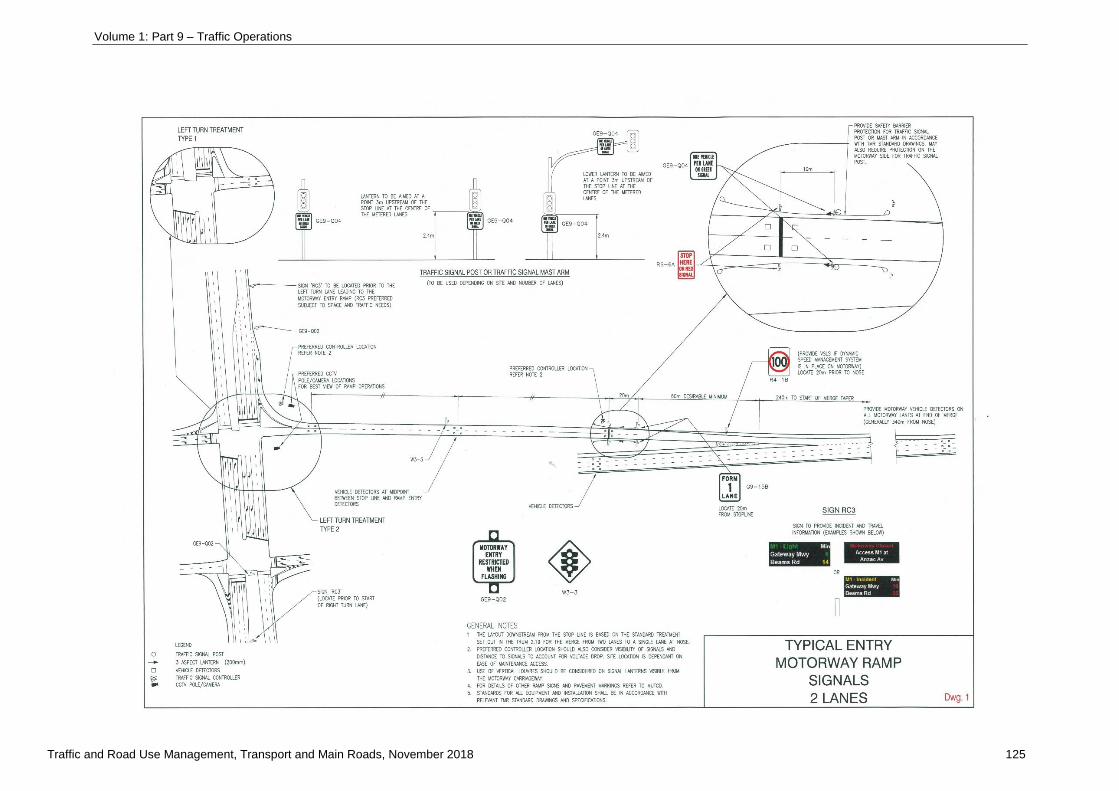
Volume 1: Part 9 – Traffic Operations
Traffic and Road Use Management, Transport and Main Roads, November 2018 125
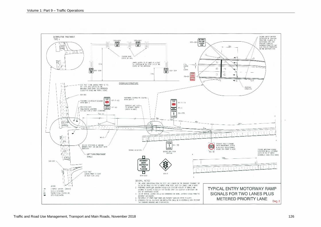
Volume 1: Part 9 – Traffic Operations
Traffic and Road Use Management, Transport and Main Roads, November 2018 126
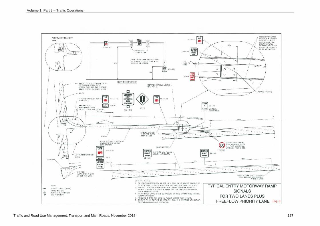
Volume 1: Part 9 – Traffic Operations
Traffic and Road Use Management, Transport and Main Roads, November 2018 127

Volume 1: Part 9 – Traffic Operations
Traffic and Road Use Management, Transport and Main Roads, November 2018 128
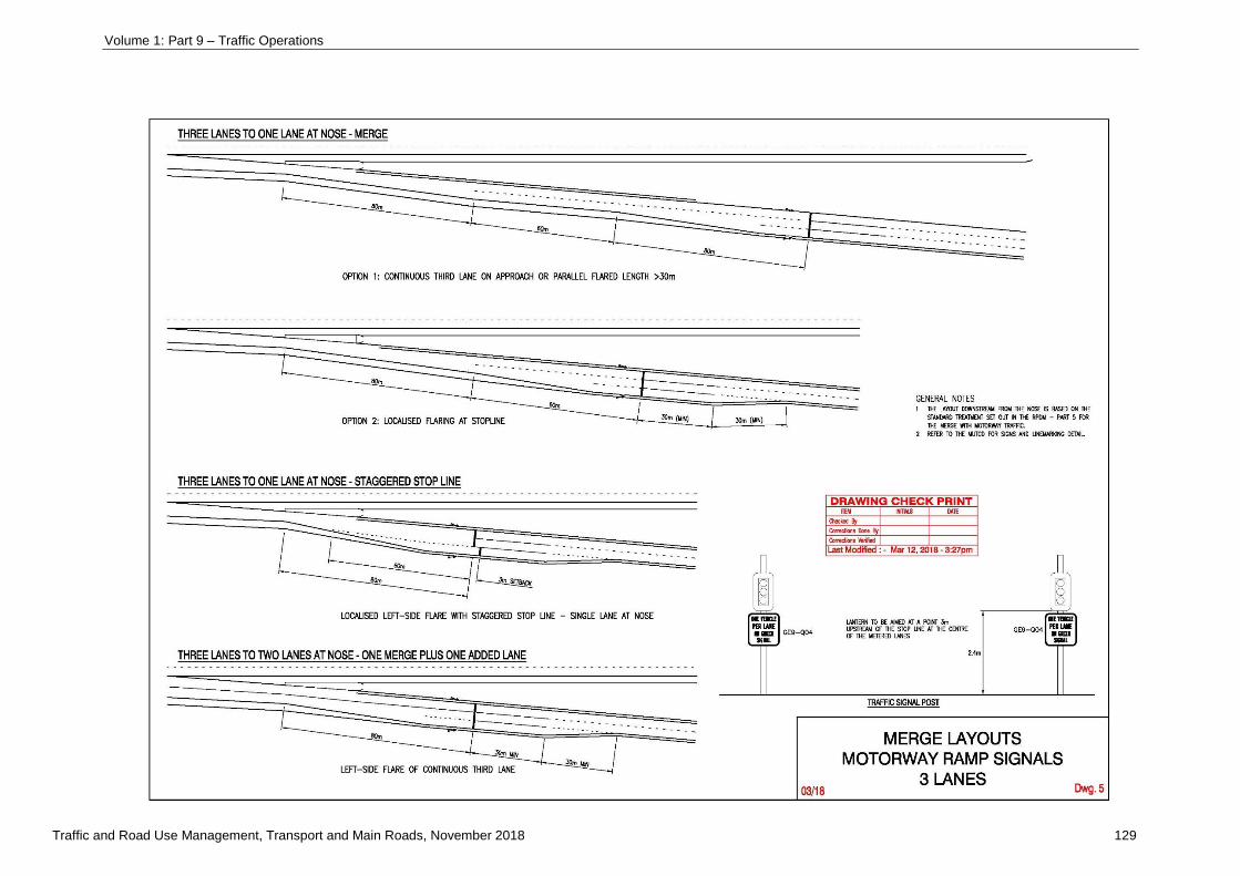
Volume 1: Part 9 – Traffic Operations
Traffic and Road Use Management, Transport and Main Roads, November 2018 129
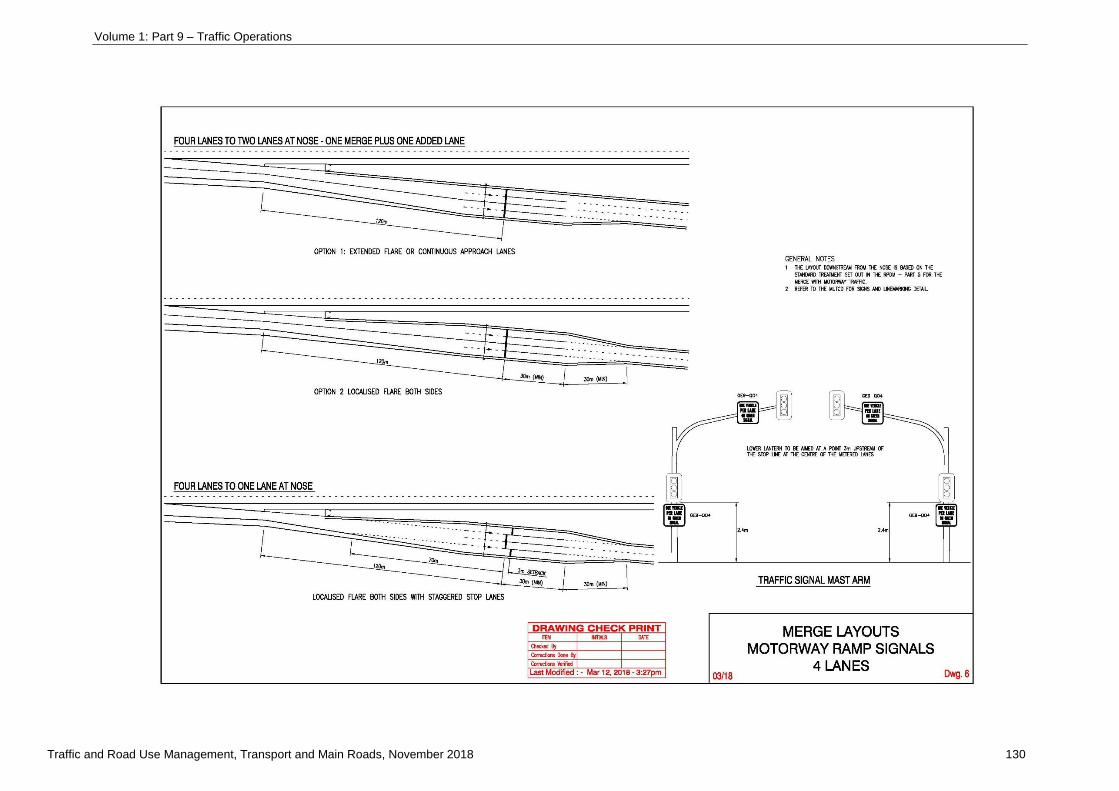
Volume 1: Part 9 – Traffic Operations
Traffic and Road Use Management, Transport and Main Roads, November 2018 130
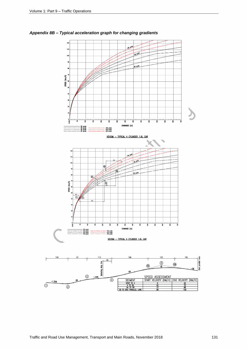
Volume 1: Part 9 – Traffic Operations
Traffic and Road Use Management, Transport and Main Roads, November 2018 131
Appendix 8B – Typical acceleration graph for changing gradients
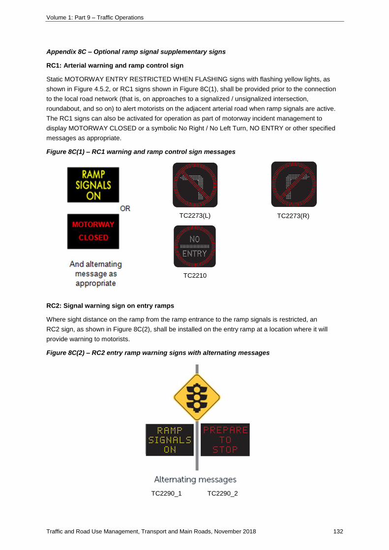
Volume 1: Part 9 – Traffic Operations
Traffic and Road Use Management, Transport and Main Roads, November 2018 132
Appendix 8C – Optional ramp signal supplementary signs
RC1: Arterial warning and ramp control sign
Static MOTORWAY ENTRY RESTRICTED WHEN FLASHING signs with flashing yellow lights, as
shown in Figure 4.5.2, or RC1 signs shown in Figure 8C(1), shall be provided prior to the connection
to the local road network (that is, on approaches to a signalized / unsignalized intersection,
roundabout, and so on) to alert motorists on the adjacent arterial road when ramp signals are active.
The RC1 signs can also be activated for operation as part of motorway incident management to
display MOTORWAY CLOSED or a symbolic No Right / No Left Turn, NO ENTRY or other specified
messages as appropriate.
Figure 8C(1) – RC1 warning and ramp control sign messages
TC2273(L) TC2273(R)
TC2210
RC2: Signal warning sign on entry ramps
Where sight distance on the ramp from the ramp entrance to the ramp signals is restricted, an
RC2 sign, as shown in Figure 8C(2), shall be installed on the entry ramp at a location where it will
provide warning to motorists.
Figure 8C(2) – RC2 entry ramp warning signs with alternating messages
TC2290_1 TC2290_2

Volume 1: Part 9 – Traffic Operations
Traffic and Road Use Management, Transport and Main Roads, November 2018 133
RC3: Arterial advance information and warning signs
Real time information signs are part of the integrated ramp signalling and traveller information systems
and are installed in advance of the ramp entrance on the arterial road to provide information to drivers
before they enter the motorway.
RC3 signs are generally installed prior to the right and left turn lanes facing each direction of
approach, Examples of RC3 sign messages are shown in Figure 8C(3).
Figure 8C(3) – RC3 real time information sign example messages
The actual sign locations generally need to be determined on site relative to other infrastructure, for
example, intersections, driveways, signs, and so on. The desirable sign minimum installation distance
prior to the decision point to enable a road user to react appropriately and the desirable separation
distance relative to other signs are provided in Table 8C(1).
Table 8C(1) – Minimum desirable sign installation distance for RC3 signs
Installation Speed environment (km/h)
60 and 70 80
Distance prior to action point 60 to 80 m 80 to 120 m
Spacing to other signs 50 m 60 m
Minimum 0.6 V m
(where ‘V’ is the 85th percentile speed in km/h)
Based on AS 1742.2-2009 (Appendix D)
Traveller information systems are used to provide travel time and other information about the
motorway’s condition as a service to motorists. They can also influence driver route choice behaviour
and thereby assist in reducing congestion and improving network efficiency. The early identification
and effective management of an incident or congestion, as well as initiation of information to drivers
can reduce motorway demand and assist in minimising the effect on traffic flow.