part 2 electrical training
TRANSCRIPT

Junction Boxes
• 8-20.3(6)• 9-29.2 junction boxes• 9-29.2(3) structure mounted JBs• 9-29.2(4) cover markings

Type 1 Junction Box
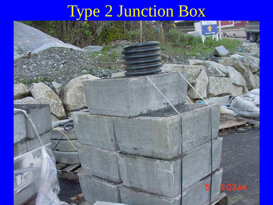
Type 2 Junction Box

Base Plate and JBType 3,7,or 8

Type 7 JBs 12-inch Deep 18-inch Deep

Type 8 Junction Box

Type 4 Junction Box

Type 4 JB

Type 6 Junction Box

Traffic Temporarily Placed Over Traffic Bearing Boxes

Pull Box With Section Out

JB Too High
When existing boxes need to be adjusted.Adjustments requiring raising or loweringJBs shall require conduit modification if the resultant clearance from conduit top,to the lid, becomes less than 6-inches or more than 10-inches.Special Provisions 8-20.3(6)

Secure the Boxes

JB with Rail Form Face in Place

JB Secured to Form Face

Adjustable JB With About 1.5-inch of Adjustment
Adjustable JB Video Clip
Adjustable JB With About 1.5-Inch of Adjustment NEMA 3X
NW Region requires adjustable boxes to be installed in “Slip Form Barriers” with adjustment bolts available with the construction lid in place. Special Prov. 9-29.2
Skip StillPictures
1

Concrete Augers up Into Machine

Here It Comes

Hold the Box Back to Let the Machine Start Over It

Holding the JB to Keep It
Out Flush

A Close Watch Helps With a Good Product

Looking Good

Box Looks Good

Pride in His Work

There It Goes
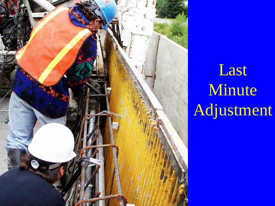
Last Minute
Adjustment

After the Machine Extrudes It

I Know There Is a Box Here Someplace

Just a Little Too Deep

Pull It Out Just a Little More

Ok Stuff It Full of Mud

Now That Looks Great

After the Pour

Inside the Box

Ground Lug Inside the Box Drain Hole Got Missed
Box Has Been Hit

Lid After It Takes a Direct Hit

Barrier Box With Extension Added

Extension Installed With Epoxy

Plexiglas Spacer and SS Lid Removed

Plexiglas Spacer SS Lid Removed

g pNW Region requires boxes in thebarrier to be parallel to barrier topwithin 1-degree. The face shall notbe more than 1/8-inch recessed. Special Provisions 8-20.3(6)

Concrete Made to Fit

Surface JB Hinge Lid

Surface Mount SS JB

Cable Vault Too High to Put on Traffic Bearing Lid

CV With Top 6 Inches Cut Off

Setting Traffic Bearing Lid

CV With Traffic Bearing Lid

Set Pull Box
Junction Box Inspection Checklist
Copy in your books
Messenger Cable
Fittings• 8-20.3(7)• 9-29.4 messenger cable fittings• 9.29.5 pole line hardware

Span System Parts

Johnny Ball Insulator With Guy Wraps Installed

Johnny Ball Insulator

Aerial Terminal Box

Wiring• 8-20.3(8)• 9-29.3 conductors, cable• 9-29.7 luminaire fusing and connections at
light standards• 9-29.12 electrical splice materials• 9-29.12(1) illumination circuit splices

Mandrels

Pulling Wire
8-20.3(5) Conduit NW Region
In conduit less than 2-inchpull ropes for wire installationshall be not less than ¼-inch.In conduits 2-inch diameter or larger, pull ropes shall be not less than ½-inch.

Wire Pull

Install Duct Seal

NW Region Requires Mechanical Conduit Plugs in All Cabinets

Make Sure They Are Ready Before The Pull Starts

Wire on Reels

Wire Connectors and Grounding Clamps

Burndy Crimp and Crimper

T & B Crimper

Crimping the Ground Wire

Epoxy Splice Kit

Heat Shrink

Heat Shrink Splice

Heat Shrink Splices

Camera Cable Termination
Properly done
Poorly Done
Corrosion Results

Use Caution Where You Drive

Fiber Optic Tugger
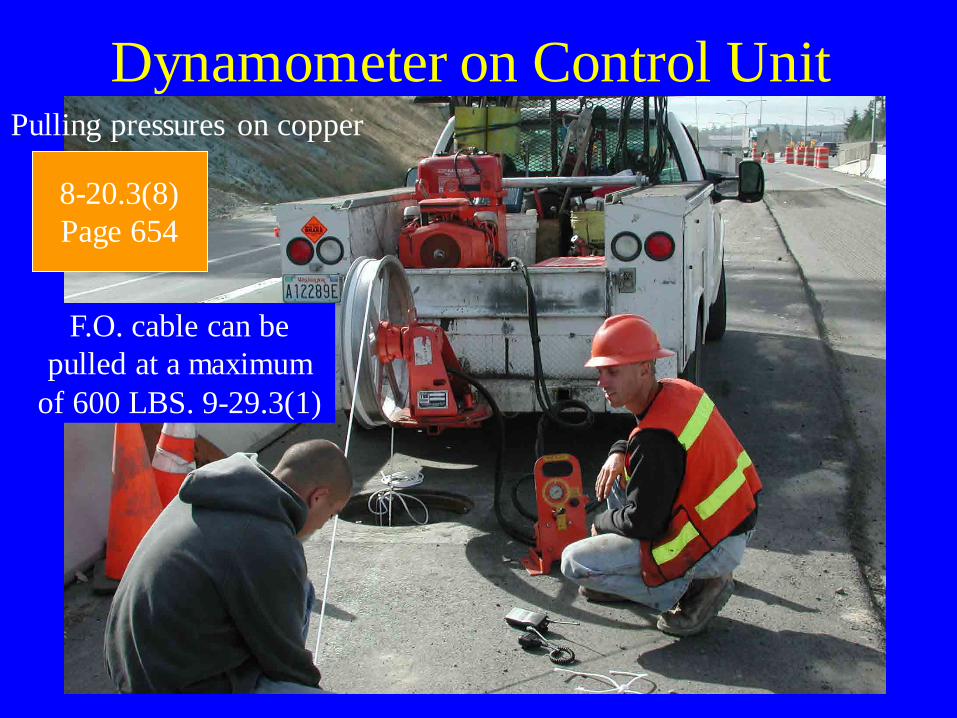
Dynamometer on Control Unit
8-20.3(8)Page 654
Pulling pressures on copper
F.O. cable can be pulled at a maximum
of 600 LBS. 9-29.3(1)

Setting Up

Pulling Cable With Ease

Cable Is Out and Pulling Around the Puller Wheel

Racking Fiber Optic Cable
NW Region Require Stainless Steel Hangers

Figure 8 Fiber Optic Rack in P.V.
NW Region Requires Stainless Steel Hangers