paralleling switchgears - electronil
TRANSCRIPT

PARALLELING SWITCHGEARS
SYNCHRONIZING | LOAD SHARING | POWER MANAGEMENT

2 . Paralleling Switchgears | Power is What We Do
1995SINCEPOWER IS WHAT WE DO
We are nearly 30 years in the Egyptian markets, and only getting better. For the last two decades, we have engineered and shaped the future, redefining what power means to people`s lives, careers and lifestyles.
WHY ELECTRONIL!We are a group of fearless thinkers, driven to empower people all over the nation – with reliable, revolutionary generators, power systems and power solutions.
We exist for one reason: to move you forward.

Paralleling Switchgears | Power Is What We Do . 3
ونيل! لماذا تختار منتجات إلك�تنحن مجموعة من المفكرين لا يخافون الإبتكار، مدفوعون بشغف
ي جميع أنحاء البلاد - بمحطات توليد طاقة ف عملائنا �ف تمك�ي
إعتمادية وموثوقة، بالإضافة إلى أنظمة وحلول متكاملة للطاقة.
نعمل بجهد لسبب واحد: للحفاظ على تقدمكم.
ي الأسواق المصرية، ة �ف من الخ�ب
لدينا ما يقرب من 30 عاما
، قمنا ف ف الماضي�ي ي تقدم دائم. على مدار العقدين الزمني�يونعمل �ف
ي بتصميم وصياغة المستقبل، وإعادة صياغة المع�ف الحقي�تللطاقة الكهربية لحياة عملائنا وأعمالهم وأنماط حياتهم.
1995SINCEPOWER IS WHAT WE DO

4 . Paralleling Switchgears | Our Story
A Magnificent force in power solutions since 1995, ELECTRONIL™ POWER SOLUTIONS is committed to reliable, intelligent products,advanced engineering and responsiveafter-sale support.
Over the years, we have amplified our well-known reputation to be a leader known for its premium range of generator-sets and control systems. Together, with building on the legacy of a leading brand, to create one of the largest generator-set and control systems providers in Egypt—and continued an unwavering focus on reliable power systems and innovation.
We deliver integrated industrial powersystems for emergency, prime and continuous applications throughout whole Egypt—from data centers and hospitals to water treatment and hospitality facilities. With a deep under-standing of your industry, we excel in design-ing customized power systems that simplify your most complex challenges.
OURSTORY
Paralleling Switchgears | Our Story . 5
ونيل لحلول الطاقة المتكاملة قوة كة إلك�ت عد �شت
ي مجالات حلول الطاقة الكهربية منذ عام رائدة �ف
م بإمداد عملائنا ف ف ونحن نل�ت 1995، ومنذ ذلك الح�ي بالإضافة
بمنتجات موثوقة وذكية ومتطورة هندسيا
إلى دعم �يــــع الاستجابة لخدمة ما بعد البيع والصيانة.
على مر الأعوام، ضاعفنا من سمعتنا المعروفة لكوننا من أك�ب الكيانات الرائدة والمعروفة بمنتجاتها ة من وحدات توليد الطاقة الكهربية وأنظمة ف المتم�يالتحكم والحماية والتشغيل. بالإضافة إلى، واستنادا
إلى إرث علامة تجارية رائدة، قمنا بإنشاء واحد من أك�ب مزودي الأسواق المصرية بأنظمة الطاقة
المتكاملة وأنظمة تحكم وتشغيل وحماية إعتمادية وموثوقة على مستوى جمهورية مصر العربية - ف المستمر على إبتكار أنظمة طاقة ك�ي واستمر ال�ت
متكاملة وموثوقة.
نقوم بتقديم أنظمة توليد طاقة صناعية متكاملة لتطبيقات الطوارئ والمحطات الرئيسية والطاقة ي جميع أنحاء جمهورية مصر العربية -
المستمرة �فمن مراكز المعلومات والمستشفيات إلى محطات
ب والصرف الصحي والفنادق. معالجة مياه ال�شي تصميم
ف �ف بدراسة وفهم عميق لمجال عملك، نتم�يي تعمل على
أنظمة طاقة متكاملة ومتخصصة وال�تي يمكن أن
تبسيط التحديات الأك�ث تعقيدا ال�تتقابلك.
مننحن

6 . Paralleling Switchgears | Total System Integration
A Power System is only as good as the parts that define it. That`s why we engineer every detail down to the last bolt. From generators and power transfer switches to paralleling systems and switchgear and controllers, everything works together seamlessly. Because we design, engineer and test it that way.
That`s the ELECTRONIL difference.
TOTAL SYSTEM INTEGRATION Everything works together, Just as it should.
Good news: There is more, behind that power system, there is a team of dedicated engineers that focuses on every ele-ment-generators, power transfer switches, switchgears and control systems-to be sure that the system you get is the sys-tem you need. You will know that your project is supported by an expert team, customized to your exact needs, brought in on budget and on time.
From spec to start-up to service, we do it all.
Paralleling Switchgears | Total System Integration . 7
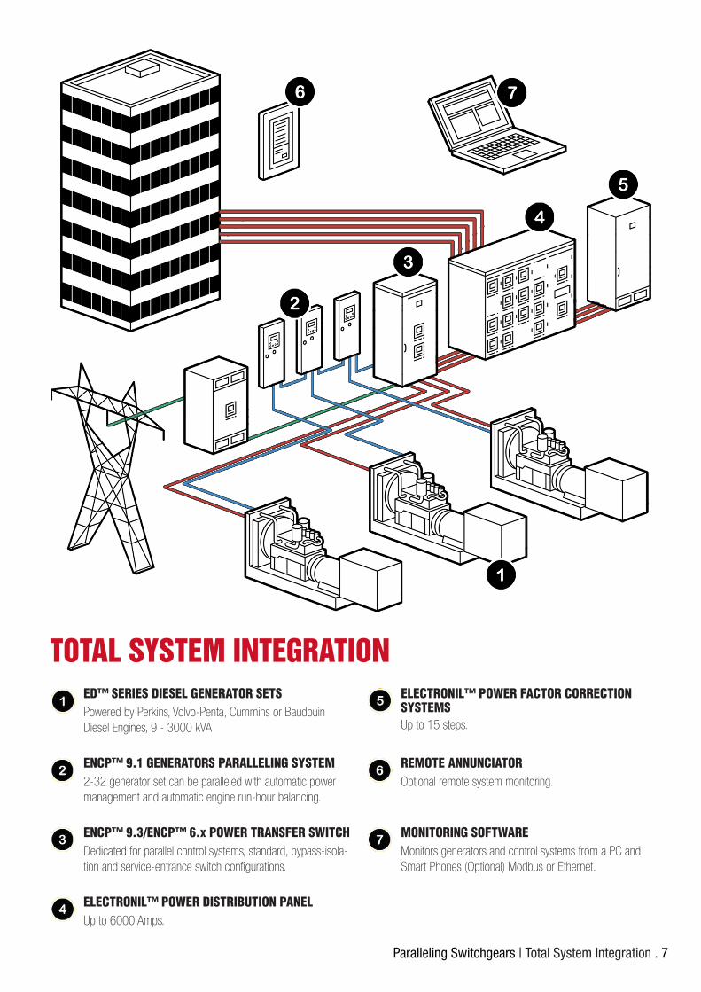
MONITORING SOFTWARE
REMOTE ANNUNCIATOR
ELECTRONIL™ POWER FACTOR CORRECTION SYSTEMS
ELECTRONIL™ POWER DISTRIBUTION PANEL
ENCP™ 9.3/ENCP™ 6.x POWER TRANSFER SWITCH
ENCP™ 9.1 GENERATORS PARALLELING SYSTEM
ED™ SERIES DIESEL GENERATOR SETS
Monitors generators and control systems from a PC and Smart Phones (Optional) Modbus or Ethernet.
Optional remote system monitoring.
Up to 15 steps.
Up to 6000 Amps.
Dedicated for parallel control systems, standard, bypass-isola-tion and service-entrance switch configurations.
2-32 generator set can be paralleled with automatic power management and automatic engine run-hour balancing.
Powered by Perkins, Volvo-Penta, Cummins or Baudouin Diesel Engines, 9 - 3000 kVA
TOTAL SYSTEM INTEGRATION
8 . Paralleling Switchgears | Benefits of Paralleling
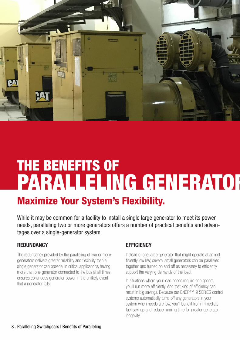
Maximize Your System’s Flexibility.
THE BENEFITS OFPARALLELING GENERATORS.While it may be common for a facility to install a single large generator to meet its power needs, paralleling two or more generators offers a number of practical benefits and advan-tages over a single-generator system.
REDUNDANCY
The redundancy provided by the paralleling of two or more generators delivers greater reliability and flexibility than a single generator can provide. In critical applications, having more than one generator connected to the bus at all times ensures continuous generator power in the unlikely event that a generator fails.
EFFICIENCY
Instead of one large generator that might operate at an inef-ficiently low kW, several small generators can be paralleled together and turned on and off as necessary to efficiently support the varying demands of the load.
In situations where your load needs require one genset, you’ll run more efficiently. And that kind of efficiency can result in big savings. Because our ENCP™ 9 SERIES control systems automatically turns off any generators in your system when needs are low, you’ll benefit from immediate fuel savings and reduce running time for greater generator longevity.
Paralleling Switchgears | Benefits of Paralleling . 9
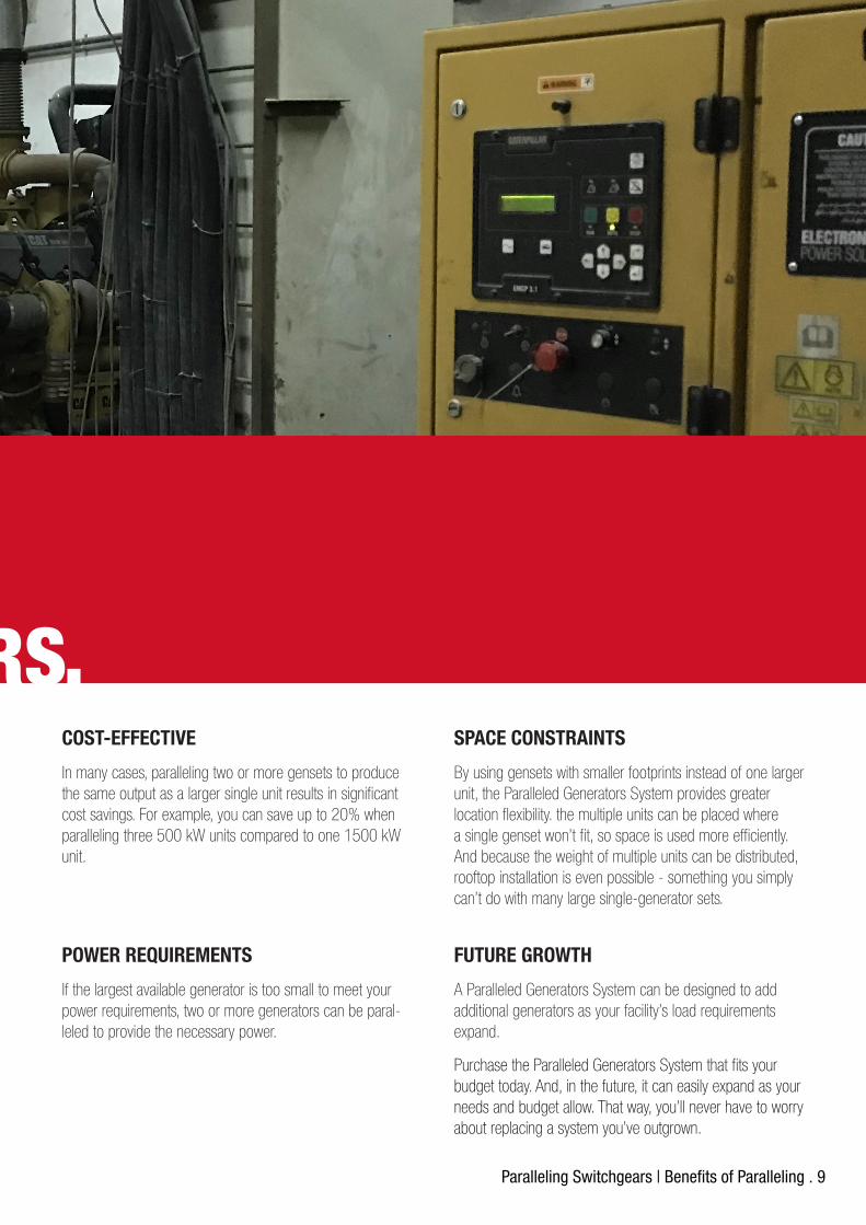
POWER REQUIREMENTS
If the largest available generator is too small to meet your power requirements, two or more generators can be paral-leled to provide the necessary power.
FUTURE GROWTH
A Paralleled Generators System can be designed to add additional generators as your facility’s load requirements expand.
Purchase the Paralleled Generators System that fits your budget today. And, in the future, it can easily expand as your needs and budget allow. That way, you’ll never have to worry about replacing a system you’ve outgrown.
COST-EFFECTIVE
In many cases, paralleling two or more gensets to produce the same output as a larger single unit results in significant cost savings. For example, you can save up to 20% when paralleling three 500 kW units compared to one 1500 kW unit.
SPACE CONSTRAINTS
By using gensets with smaller footprints instead of one larger unit, the Paralleled Generators System provides greater location flexibility. the multiple units can be placed where a single genset won’t fit, so space is used more efficiently. And because the weight of multiple units can be distributed, rooftop installation is even possible - something you simply can’t do with many large single-generator sets.
THE BENEFITS OFPARALLELING GENERATORS.
10 . Paralleling Switchgears | Our Proven Process
We carefully consider your requirements and develops a solution that meets your needs. Every design starts with our proven, time-tested process that builds your system to your exact requirements.
Our experienced engineering team helps you every step of the way, determining and specifying your requirements, designing the system and providing easy-to-read drawings and documentation. ELECTRONIL’s rigorous testing and careful commissioning ensure that your paralleling switchgear is always ready to supply generator power when needed.
THE ELECTRONIL DIFFERENCE.OUR PROVEN PROCESS.
Paralleling Switchgears | Intutive User Interface . 11
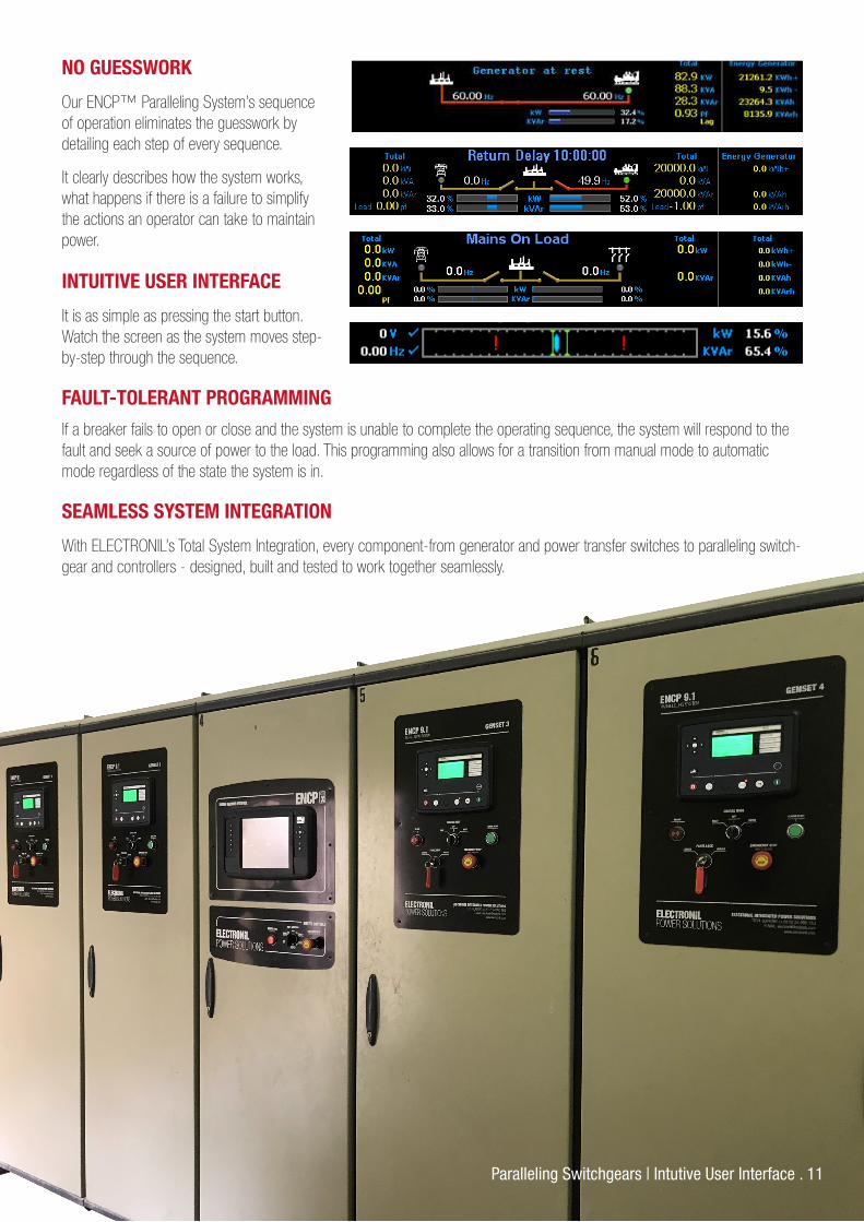
INTUITIVE USER INTERFACE
It is as simple as pressing the start button. Watch the screen as the system moves step-by-step through the sequence.
NO GUESSWORK
Our ENCP™ Paralleling System’s sequence of operation eliminates the guesswork by detailing each step of every sequence.
It clearly describes how the system works, what happens if there is a failure to simplify the actions an operator can take to maintain power.
SEAMLESS SYSTEM INTEGRATION
With ELECTRONIL’s Total System Integration, every component-from generator and power transfer switches to paralleling switch-gear and controllers - designed, built and tested to work together seamlessly.
FAULT-TOLERANT PROGRAMMING
If a breaker fails to open or close and the system is unable to complete the operating sequence, the system will respond to the fault and seek a source of power to the load. This programming also allows for a transition from manual mode to automatic mode regardless of the state the system is in.
12 . Paralleling Switchgears | Typical Paralleling Applications
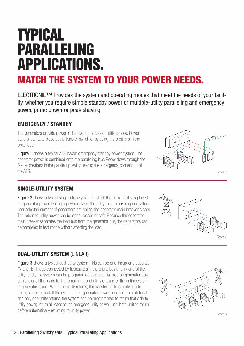
EMERGENCY / STANDBY
The generators provide power in the event of a loss of utility service. Powertransfer can take place at the transfer switch or by using the breakers in the switchgear.
Figure 1 shows a typical ATS-based emergency/standby power system. Thegenerator power is combined onto the paralleling bus. Power flows through the feeder breakers in the paralleling switchgear to the emergency connection ofthe ATS.
TYPICAL PARALLELING APPLICATIONS.MATCH THE SYSTEM TO YOUR POWER NEEDS.ELECTRONIL™ Provides the system and operating modes that meet the needs of your facil-ity, whether you require simple standby power or multiple-utility paralleling and emergency power, prime power or peak shaving.
SINGLE-UTILITY SYSTEM
Figure 2 shows a typical single-utility system in which the entire facility is placed on generator power. During a power outage, the utility main breaker opens; after a user-selected number of generators are online, the generator main breaker closes. The return to utility power can be open, closed or soft. Because the generator main breaker separates the load bus from the generator bus, the generators can be paralleled in test mode without affecting the load.
DUAL-UTILITY SYSTEM (LINEAR)
Figure 3 shows a typical dual-utility system. This can be one lineup or a separate “N and “B” lineup connected by tiebreakers. If there is a loss of only one of the utility feeds, the system can be programmed to place that side on generator pow-er, transfer all the loads to the remaining good utility or transfer the entire system to generator power. When the utility returns, the transfer back to utility can be open, closed or soft. If the system is on generator power because both utilities fail and only one utility returns, the system can be programmed to return that side to utility power, return all loads to the one good utility or wait until both utilities return before automatically returning to utility power.
Figure 1
Figure 2
Figure 3

Paralleling Switchgears | Typical Paralleling Applications . 13
DUAL-UTILITY SYSTEM (RING)
Figure 4 shows a typical dual-utility system in which the utility bus and generator bus are separate lineups. The available sequence of operations is similar to the linear dual-utility system.
The advantage of the ring dual-utility configuration over the linear configuration are:
• The ability to feed the entire system with one utility feed without energizing the generator paralleling bus.
• The ability to automatically respond to the generator’s main breakers failing to close and provide an alternate path to feed generator power to the load.
BASE LOAD MODE
The generators remain paralleled to the utility, producing power at a preset base load level. If the facility’s load is less than the base load set point, the extra power is exported to the utility. As shown in Figure 5, the shaded area is generator power exported to utility.
PEAK SHAVE
Peak shaving reduces your facility’s electrical power consumption during periods of high demand on the power utility. A peak shave system can remain paralleled to the utility or remove your facility’s loads from the utility and place them on generator power.
Figure 4
Figure 5
IMPORT MODE
The generators remain paralleled to the utility, producing power and maintaining a preset kW level flowing in from the utility. Generator output varies to support the load and maintain the fixed amount of power from the utility.
If the load is high, the maximum generator output is limited to the base load kW set point. Figure 6 shows the generator output ranging with load to maintain constant power from the utility. Figure 6
INTERRUPTIBLE MODE
The generators are paralleled to the utility, the facility load is transferred from the utility to the generators, and the main breaker opens, separating the facility from the utility.
14 . Paralleling Switchgears | Its all about the Controls
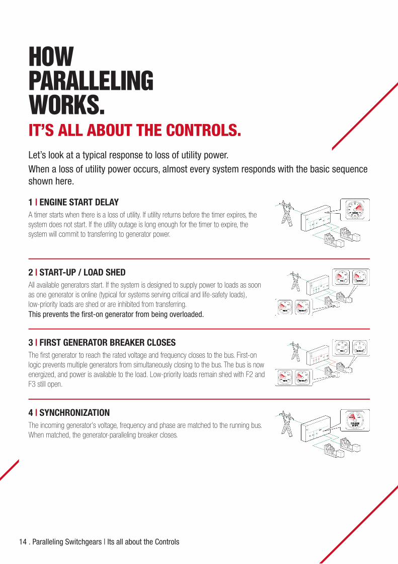
1 | ENGINE START DELAY A timer starts when there is a loss of utility. If utility returns before the timer expires, the system does not start. If the utility outage is long enough for the timer to expire, the system will commit to transferring to generator power.
HOW PARALLELING WORKS.IT’S ALL ABOUT THE CONTROLS.Let’s look at a typical response to loss of utility power. When a loss of utility power occurs, almost every system responds with the basic sequence shown here.
2 | START-UP / LOAD SHED All available generators start. If the system is designed to supply power to loads as soon as one generator is online (typical for systems serving critical and life-safety loads), low-priority loads are shed or are inhibited from transferring.This prevents the first-on generator from being overloaded.
3 | FIRST GENERATOR BREAKER CLOSES The first generator to reach the rated voltage and frequency closes to the bus. First-on logic prevents multiple generators from simultaneously closing to the bus. The bus is now energized, and power is available to the load. Low-priority loads remain shed with F2 and F3 still open.
4 | SYNCHRONIZATION The incoming generator’s voltage, frequency and phase are matched to the running bus. When matched, the generator-paralleling breaker closes.

Paralleling Switchgears | Its all about the Controls . 15
5 | SECOND GENERATOR BREAKER CLOSES / LOAD SHARINGAdditional generator power is available to the load. The system’s load-sharing controls actively control the kW and kVAr output of each generator in order to proportionally share the load (according to the power ratio of each generator) and maintain rated frequency and voltage.
6 | LOAD MANAGEMENTAs additional generators close to the bus, more power is available for the load. The load management of the system actively adds loads based on bus capacity available.
7 | POWER MANAGEMENTPower management optimizes the number of online generators based on the load’s kW demand, starting and stopping generators as required. Generators are sequenced on in order of operator-assigned priority (or based on runtime) and taken off in reverse priority.
Operator-defined set points determine the percent load level and time delay at which the genset will be brought on or taken offline.
16 . Paralleling Switchgears | Synchronization
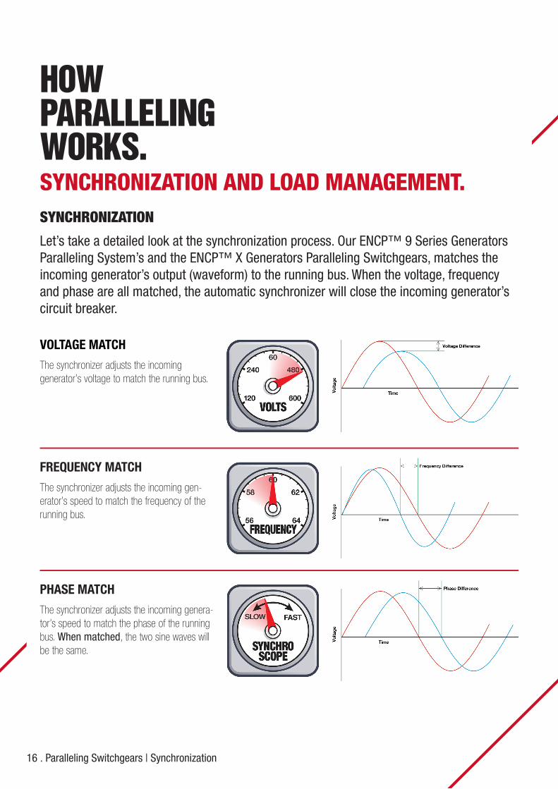
HOW PARALLELING WORKS.SYNCHRONIZATION AND LOAD MANAGEMENT.SYNCHRONIZATION
Let’s take a detailed look at the synchronization process. Our ENCP™ 9 Series Generators Paralleling System’s and the ENCP™ X Generators Paralleling Switchgears, matches the incoming generator’s output (waveform) to the running bus. When the voltage, frequency and phase are all matched, the automatic synchronizer will close the incoming generator’s circuit breaker.
VOLTAGE MATCH
The synchronizer adjusts the incominggenerator’s voltage to match the running bus.
FREQUENCY MATCH
The synchronizer adjusts the incoming gen-erator’s speed to match the frequency of the running bus.
PHASE MATCH
The synchronizer adjusts the incoming genera-tor’s speed to match the phase of the running bus. When matched, the two sine waves will be the same.
Paralleling Switchgears | Load Management . 17
LOAD MANAGEMENT (Optional Feature)
Each load is assigned to a priority level. Load management determines when priority levels are signaled to disconnect (shed) and reconnect (add). When multiple generators are online, load management matches the load to the generator capacity.
The system can control feeder breakers or transfer switches. Dry contacts or communica-tions can be provided (upon request) to interface with your building-management system (BMS).
In a paralleled generator system, it is imperative to plan for the unlikely event of a generator failure. Removing or shedding load prevents the remaining online generators from overload-ing and tripping offline.
Load Add
Loads can be added based on severalconsiderations including:
• Generator bus capacity: Loads are added based on the kW capacity of the bus and an assumed kW demand of the load.
• Number of generators on line: Loads are added based on how many gen-erators are connected to the bus; this is most effective in systems with same-size generators.
Load Shed
A load-shed event can be triggered bymultiple parameters including:
• Generator failure: Loads are shed based on the number of failed gensets.
• kW overload: When the generators reach their overload set points, low-priority loads sequentially shed until the load falls below the overload set point.
• Under frequency: Under frequency is often an indication that the generators are fully loaded and cannot supply additional power to the load. When the bus frequency reaches its under fre-quency set point, preset loads are shed.

18 . Paralleling Switchgears | Transition Types
Example
Closed transfer from generator power to utility power after a power outage.
ELECTRONIL™ Paralleling Switchgears can be configured with the transition type you need. From a basic open to a soft (ramp) transfer, ELECTRONIL™ Will customize your system to meet your requirements.
TRANSITION TYPES.Customized to Your Needs.
CLOSED TRANSFER In a closed transfer, the source from which the load is being transferred and the source to which the load will be transferred are connected together momentarily. After both sources are closed, the source from which power is being transferred is opened. If the system is configured for fast transfer, the source from which the power is being transferred will open within 100ms. if the system is configured for soft (ramp) transfer, the load will be transferred at a user-adjustable kW/sec rate until the source from which the power is being transferred reaches the low-load set point. The load remains energized during the transfer from one source to the other.
G1
M1
F1
G1
M1
F1
G1
M1
F1
STEP 1Utility power return timer expires(M1 Open / G1 Closed)
STEP 2After the generator is in synch with theutility, M1 closes (M1 Closed / G1 Closed)
STEP 3FAST TRANSFER: G1 opens within 100msSOFT TRANSFER: G1 opens after thegenerator ramps down to its unloadedsetpoint (M1 Closed / G1 Open)
Example
Open transfer from generator power to utility power after a power outage.
OPEN TRANSFER The load is disconnected from one source before being connected to the other source. The load is without power for theduration of the open-transfer time delay.
G1
M1
F1
G1
M1
F1
G1
M1
F1
STEP 1Utility power return timer expires(M1 Open / G1 Closed)
STEP 2G1 opens and the open transfertimer starts (M1 Open / G1 Open)
STEP 3Open transfer timer expires, M1closes (M1 Closed / G1 Open)
Paralleling Switchgears | Sequence of Operation . 19
SEQUENCE OF OPERATION.System Response Step-By-Step.
ELECTRONIL’s Unique approach to our sequence of operation differs from the typical narrative-based sequence.
Ours is a fixed flowchart that eliminates the guess-work and ambiguity from knowing how your system will respond to normal operation (ie, mains abnormal).
• Easy to understand.• Clearly shows system response, and timing of
response.• Provides an LED for each power source and
each circuit breaker status.
SYSTEM RESPONSEThis lists the steps the system takes from initial state to final state:
• The initial state shows the status of each breaker in the transfer sequence and the status of each power source in the system.
• The first step is the triggering event that starts the sequence. This could be the receipt of a remote start signal, a utility grid failure or an operator pushing a start button.
• Next is a description of each step required to get to the final desired state, along with the corre-sponding system response.
• Finally, the final state for each circuit breaker is described, along with the power status of each bus in the system.
Generally, for each response that involves a circuit breakeropening or closing or a timer starting, the system will issuean alarm message describing if a circuit breaker fails to open,a circuit breaker fails to close, no power source to load or somethinghappens to prevent a timer from timing out. Other responses as ifa generator fails to start, a generator fails while running or a generatorbecomes overloaded is described as well.

20 . Paralleling Switchgears | Intuitive Operation
The operator interface monitors and controls the system and is customized to your project.
It is specifically designed and chosen to be user-friendly and eliminate guesswork, letting the operator focus on the task at hand instead ofwondering how to navigate through the screens.
Whether the user is advanced or a first-time operator of the system, the ELECTRONIL™ ENCP™ 9 Series Generator Paralleling Systems, and ENCP™ X Generator Paralleling Switchgears interface provides theinformation in a simple but comprehensive way.
THE OPERATOR INTERFACES.System Control at Your Fingertips.
INTUITIVE OPERATION With basic knowledge of paralleling switchgears, the operator can navigate the system simply and intuitively without reading a manual. The intuitive interface eliminates fear of operational errors by clearly showing each step in the sequence before initiated.
THE RIGHT INFORMATIONAT THE RIGHT TIME By providing pertinent information on each screen, the operator always knows the status of each power source and each circuit breaker in thesystem.

Paralleling Switchgears | Examples of Controls . 21
THE OPERATOR INTERFACES.Examples of Controls.
HUMAN MACHINE INTERFACE (ENCP™ X)
• Offers comprehensive large screen graphs, charts, metering, trend analysis, power display and engine status information in a clear image and text format.
• User selectable display (widgets) allow customization of the lower part of the 10” screen.
• RS232, RS485 and Ethernet communications.• Configurable display options, with protected front panel
configuration.• Data communication link allows remote system management.
UTILITY GRID SCREEN (ENCP™ 9.3)
• Used to monitor and control the transfer from generators power to utility-grid power.
• Contains typical controls such as 5-buttos navigation keypad, system modes of operation (OFF/MANUAL/TEST/AUTO/START) buttons, ALARM MUTE button, and Source-Changeover manual control buttons.
• Shows utility-grid and generators parallel bus status and metering information.
GENERATOR SCREEN (ENCP™ 9.1)
• Used to monitor and manually control the generator set.• Contains typical controls such as 5-buttos navigation keypad,
generator set modes of operation (OFF/MANUAL/AUTO/START) buttons, ALARM MUTE button, and Circuit Breaker manual control buttons.
• Shows generator set status and metering information.
22 . Paralleling Switchgears | ENCP™ 9 Series Paralleling Systems
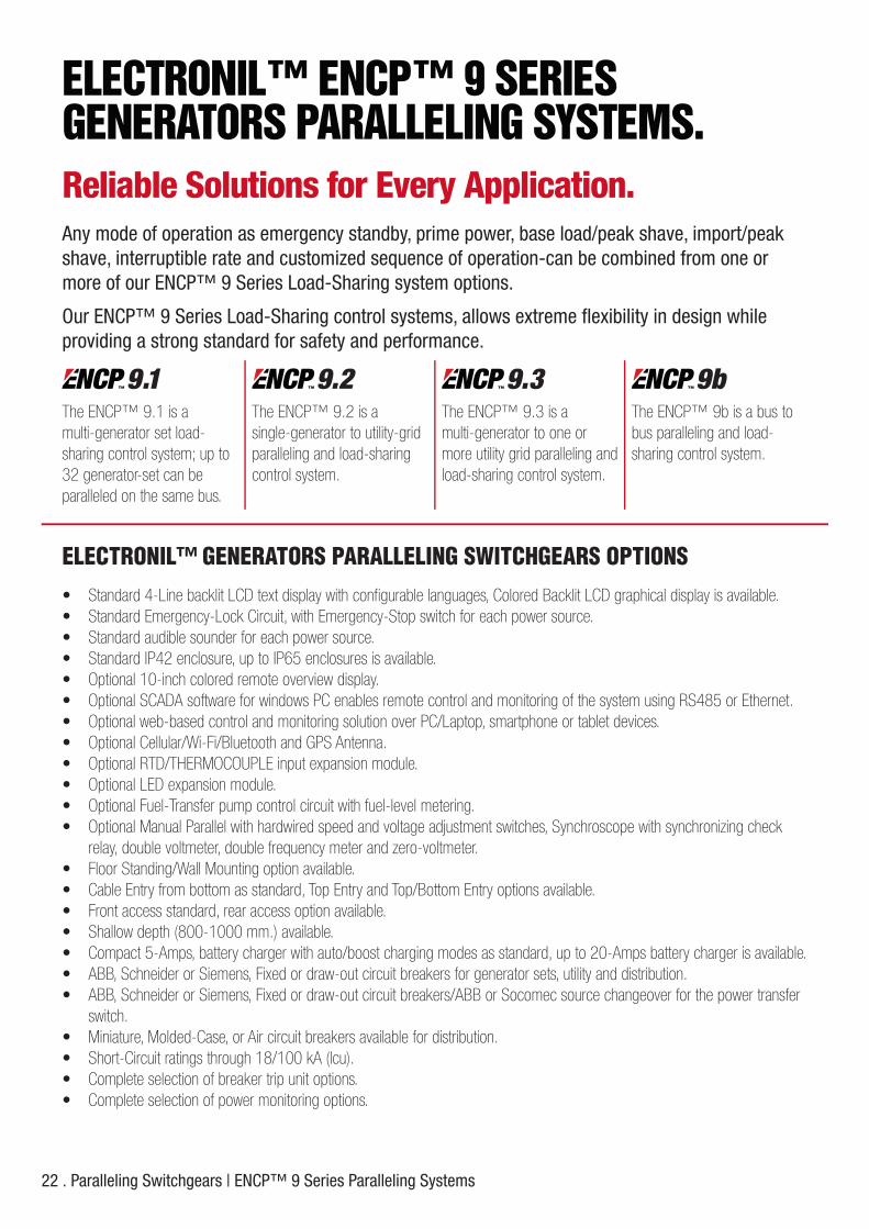
ELECTRONIL™ ENCP™ 9 SERIESGENERATORS PARALLELING SYSTEMS.Reliable Solutions for Every Application.Any mode of operation as emergency standby, prime power, base load/peak shave, import/peak shave, interruptible rate and customized sequence of operation-can be combined from one or more of our ENCP™ 9 Series Load-Sharing system options.
Our ENCP™ 9 Series Load-Sharing control systems, allows extreme flexibility in design while providing a strong standard for safety and performance.
ELECTRONIL™ GENERATORS PARALLELING SWITCHGEARS OPTIONS • Standard 4-Line backlit LCD text display with configurable languages, Colored Backlit LCD graphical display is available.• Standard Emergency-Lock Circuit, with Emergency-Stop switch for each power source.• Standard audible sounder for each power source.• Standard IP42 enclosure, up to IP65 enclosures is available.• Optional 10-inch colored remote overview display.• Optional SCADA software for windows PC enables remote control and monitoring of the system using RS485 or Ethernet.• Optional web-based control and monitoring solution over PC/Laptop, smartphone or tablet devices.• Optional Cellular/Wi-Fi/Bluetooth and GPS Antenna.• Optional RTD/THERMOCOUPLE input expansion module.• Optional LED expansion module.• Optional Fuel-Transfer pump control circuit with fuel-level metering.• Optional Manual Parallel with hardwired speed and voltage adjustment switches, Synchroscope with synchronizing check
relay, double voltmeter, double frequency meter and zero-voltmeter.• Floor Standing/Wall Mounting option available.• Cable Entry from bottom as standard, Top Entry and Top/Bottom Entry options available.• Front access standard, rear access option available.• Shallow depth (800-1000 mm.) available.• Compact 5-Amps, battery charger with auto/boost charging modes as standard, up to 20-Amps battery charger is available.• ABB, Schneider or Siemens, Fixed or draw-out circuit breakers for generator sets, utility and distribution.• ABB, Schneider or Siemens, Fixed or draw-out circuit breakers/ABB or Socomec source changeover for the power transfer
switch.• Miniature, Molded-Case, or Air circuit breakers available for distribution.• Short-Circuit ratings through 18/100 kA (lcu).• Complete selection of breaker trip unit options.• Complete selection of power monitoring options.
The ENCP™ 9.1 is a multi-generator set load-sharing control system; up to 32 generator-set can beparalleled on the same bus.
The ENCP™ 9.2 is a single-generator to utility-grid paralleling and load-sharing control system.
The ENCP™ 9.3 is a multi-generator to one or more utility grid paralleling and load-sharing control system.
The ENCP™ 9b is a bus to bus paralleling and load-sharing control system.

Paralleling Switchgears | Service and Support . 23
THE BEST WAY TOPROTECT YOUR POWER.And Protect Your Team.Our genuine parts are easily accessible, which can reduce customer downtime, improve your respon-siveness and provide a competitive advantage.
Structured to help you deliver top-tier service and capture profits, our Aftermarket Parts and Service team provides the parts, people and performance you can count on.
PARTSDesigned to perform under the toughest environmental conditions, Our Genuine Parts are chosen specifically for your generator—and will be available when you need them. They undergo extensive lab and field testing as part of the overall power-system to ensure everything works as expected.
PEOPLEOur experienced Aftermarket Parts and Service team is available to answer your questions. Choosing genuine parts provides you with comprehensive support, training and technical assistance straight from the factory.
• Factory training• On-site technical support• One point of contact for all your parts and service needs• Dedicated aftermarket channel support
PERFORMANCEWe continuously invest in better processes that make your job easier, and we’re here to support you in decisions that affect your business.
• Inventory management• Warranty management• Lead-time strategy

All data provided in this document is non-binding. This data serves informational purposes only and is especially not guaranteed in any way. Depending upon the subsequent specific individual projects, the relevant data may be subject to changes and will be assessed and determined individually for each project. This will depend on the particular characteristics of each individual project, especially specific site and operational conditions.
ELECTRONIL HEADQUARTERS63 Engineer Abdel Moneim St., Zahraa El Maadi, Cairo - Egypt
Tel/Fax : +202 25 400 286E Mail : [email protected]
SALES AND SPARE PARTSMobile : +20100 140 7173E Mail : [email protected]
TECHNICAL SUPPORTMobile : +20122 49 90 163E Mail : [email protected]
SERVICE AND MAINTENANCEMobile : +20100 69 48 681E Mail : [email protected]
www.electronil.com
POWER GENERATORS | POWER TRANSFER SWITCHES | PARALLELING SYSTEMS | SWITCHGEARS | CONTROLSGENERATOR MAINTENANCE | SERVICE AGREEMENT | CONTROL SYSTEM UPGRADE | SPARE PARTS | CONSUMABLES
Learn more at electronil.com/paralleling-switchgears