p1: ote/ote/sph p2: ote system design for ...dl.booktolearn.com/ebooks2/engineering/...3.2 advantech...
TRANSCRIPT

P1: OTE/OTE/SPH P2: OTEFM BLBK307-Bachmutsky August 30, 2010 15:13 Printer Name: Yet to Come
SYSTEM DESIGN FORTELECOMMUNICATIONGATEWAYS
Alexander BachmutskyNokia Siemens Networks, USA
A John Wiley and Sons, Ltd., Publication

P1: OTE/OTE/SPH P2: OTEFM BLBK307-Bachmutsky August 30, 2010 15:13 Printer Name: Yet to Come

P1: OTE/OTE/SPH P2: OTEFM BLBK307-Bachmutsky August 30, 2010 15:13 Printer Name: Yet to Come
SYSTEM DESIGN FORTELECOMMUNICATIONGATEWAYS

P1: OTE/OTE/SPH P2: OTEFM BLBK307-Bachmutsky August 30, 2010 15:13 Printer Name: Yet to Come
P1: OTE/OTE/SPH P2: OTEFM BLBK307-Bachmutsky August 30, 2010 15:13 Printer Name: Yet to Come
SYSTEM DESIGN FORTELECOMMUNICATIONGATEWAYS
Alexander BachmutskyNokia Siemens Networks, USA
A John Wiley and Sons, Ltd., Publication

P1: OTE/OTE/SPH P2: OTEFM BLBK307-Bachmutsky August 30, 2010 15:13 Printer Name: Yet to Come
This edition first published 2011C© 2011 John Wiley & Sons, Ltd
Registered officeJohn Wiley & Sons Ltd, The Atrium, Southern Gate, Chichester, West Sussex, PO19 8SQ, United Kingdom
For details of our global editorial offices, for customer services and for information about how to apply for permission toreuse the copyright material in this book please see our website at www.wiley.com.
The right of the author to be identified as the author of this work has been asserted in accordance with the Copyright,Designs and Patents Act 1988.
All rights reserved. No part of this publication may be reproduced, stored in a retrieval system, or transmitted, in any formor by any means, electronic, mechanical, photocopying, recording or otherwise, except as permitted by the UK Copyright,Designs and Patents Act 1988, without the prior permission of the publisher.
Wiley also publishes its books in a variety of electronic formats. Some content that appears in print may not be available inelectronic books.
Designations used by companies to distinguish their products are often claimed as trademarks. All brand names andproduct names used in this book are trade names, service marks, trademarks or registered trademarks of their respectiveowners. The publisher is not associated with any product or vendor mentioned in this book. This publication is designed toprovide accurate and authoritative information in regard to the subject matter covered. It is sold on the understanding thatthe publisher is not engaged in rendering professional services. If professional advice or other expert assistance is required,the services of a competent professional should be sought.
This publication is not authorized or endorsed by Nokia Siemens Networks.
Library of Congress Cataloging-in-Publication Data
Bachmutsky, Alexander.System design for telecommunication gateways / Alexander Bachmutsky.
p. cm.Includes bibliographical references and index.ISBN 978-0-470-74300-3 (cloth)1. Gateways (Computer networks) 2. Internetworking (Telecommunication) 3. Telecommunication systems–Design
and construction. I. Title.TK5105.543.B33 2010004.6–dc22
2010022114
A catalogue record for this book is available from the British Library.
Print ISBN 9780470743003 (H/B)ePDF ISBN: 9780470710753oBook ISBN: 9780470710746
Typeset in 10/12pt Times by Aptara Inc., New Delhi, India

P1: OTE/OTE/SPH P2: OTEFM BLBK307-Bachmutsky August 30, 2010 15:13 Printer Name: Yet to Come
This book is dedicated to my parents, Sophie and Victor,for their unconditional and unlimited love and support.
I love you very much.

P1: OTE/OTE/SPH P2: OTEFM BLBK307-Bachmutsky August 30, 2010 15:13 Printer Name: Yet to Come

P1: OTE/OTE/SPH P2: OTEFM BLBK307-Bachmutsky August 30, 2010 15:13 Printer Name: Yet to Come
Contents
List of Figures ix
List of Tables xvii
Abbreviations xix
1 Introduction 1
2 System View 32.1 System Architecting 32.2 Platform-Based Approach 62.3 System Verification 14
3 Hardware Technologies and Platforms 173.1 Different Form Factors 17
3.1.1 Proprietary 1U/2U/4U Chassis 183.1.2 Standard-Based Systems 353.1.3 IBM Blade Center 803.1.4 Comparison of Form Factors 83
3.2 Stacking Chassis 843.3 Cluster Computing 863.4 Inter-Blade Interconnect 88
3.4.1 Switch Fabric Technologies 893.4.2 Bandwidth Estimation and QoS in the Switch Fabric 943.4.3 Commercial Switch Fabric 97
3.5 Hardware Solutions for Data, Control and Management PlanesProcessing 1053.5.1 General Purpose CPUs 1083.5.2 FPGAs and ASICs 1103.5.3 Network Processors 1343.5.4 Classification Processors and Co-Processors 1583.5.5 Content Processors 1603.5.6 Multicore Processors 1893.5.7 Graphic Processors 2753.5.8 Massively Parallel Processor Array Chips 2863.5.9 Traffic Management 287

P1: OTE/OTE/SPH P2: OTEFM BLBK307-Bachmutsky August 30, 2010 15:13 Printer Name: Yet to Come
viii Contents
3.5.10 Data Plane and Control Plane Scalability 2973.5.11 Redundancy for Carrier Grade Solutions 298
4 Software Technologies and Platforms 3034.1 Basic Software Platform 303
4.1.1 Operating Systems 3034.1.2 Networking Stacks 309
4.2 Expanded Software Platform 3174.2.1 Middleware 3184.2.2 Management Plane 4024.2.3 Deep Packet Inspection and Other Software 412
4.3 Single-Threaded and Multi-X Software Designs 4174.3.1 Industry Opinions about Different Design Types 4184.3.2 Single-Threaded Design 4194.3.3 Multi-Threaded Design 4234.3.4 Multi-Process Design 4254.3.5 Multi-Instance Design 4284.3.6 Co-Location and Separation of Platform and Application 4324.3.7 Multicore Design 4344.3.8 Fine-Grained Task-Oriented Programming Model 4364.3.9 Multicore Performance Tuning 443
4.4 Partitioning OS and Virtualization 4494.4.1 Commercial and Open Source Embedded Hypervisor Offerings 4594.4.2 Hypervisor Benchmarking 463
References 465
Trademarks 467
Index 469
P1: OTE/OTE/SPH P2: OTEFM BLBK307-Bachmutsky August 30, 2010 15:13 Printer Name: Yet to Come
List of Figures
2.1 Simplified business processes 52.2 Cost and Time Estimates for Proprietary, COTS, and Application-Ready
Platforms 72.3 Use platforms to control total lifetime cost of ownership 92.4 Experience with software reuse 102.5 Organizational change with common platform 123.1 Advantech NCP-5120 with dual Cavium Networks OCTEON Plus
multicore 193.2 Advantech NCP-5120 block diagram 203.3 Bivio 7000 Network Appliance 213.4 Bivio stackability using classification-based load balancing 223.5 T5440 (open boxes are shown), and SPARC Enterprise T5120 243.6 Block diagram of the Sun SPARC Enterprise T5120/T5220 253.7 Sun SPARC Enterprise T5140 Server 263.8 Sun UltraSparc T2 Plus Netra T5440 block diagram 273.9 Sun SPARC Enterprise T5140 and T5240 block diagram 283.10 Sun utilities for Netra platforms 303.11 Sun SPARC Enterprise T5440 block diagram 313.12 Sun Netra Data Plane Suite 333.13 Sun virtualization with data plane processing 343.14 Sun/Aricent WiMAX ASN-GW reference application 353.15 Example of a PICMG 1.3 board 383.16 System Architecture with Serial Interconnect 383.17 System Architecture with Parallel Interconnect 393.18 System Architecture with Serial and Parallel Interconnects 403.19 ATCA NetraTM CT900 shelf from Sun 413.20 Mid Plane design 423.21 Caspian E1112 RTM 433.22 Sun Netra CP3200 ARTM-HDD with dual 2.5′′ HDD and additional
interfaces 433.23 ATCA Ethernet Cost vs. Benefit Analysis 453.24 Fujitsu 26-port 10 Gbps switch with Serial 10 GBASE-KR Ethernet 463.25 Priority PAUSE vs. Traditional PAUSE 473.26 TCP/IP with and without RDMA 48

P1: OTE/OTE/SPH P2: OTEFM BLBK307-Bachmutsky August 30, 2010 15:13 Printer Name: Yet to Come
x List of Figures
3.27 OS Bypass with iWARP 483.28 iWARP vs. InfiniBand – Performance and CPU efficiency 493.29 InfiniBand Roadmap for performance improvement 513.30 PCIe-to-PCI Bridge Performance problem example 533.31 Flexible topologies with Advanced Switching 543.32 Multiple protocols tunneling through Advanced Switching 543.33 Mobile Switching Center Architecture using Serial RapidIO interconnect 563.34 RapidIO Technology and Application Roadmap 573.35 Freescale QorIQ P4080 Communications Processor with integrated
Serial RapidIO interconnect 573.36 AppliedMicro 460GT in a 3G Modem Card with RapidIO connectivity 583.37 Cavium Networks OCTEON Plus CN63XX Block Diagram with Serial
RapidIO ports 593.38 32-Port Switch with Eight PRS Q-64G or PRS Q-80G 603.39 AppliedMicro PRS Evaluation System 613.40 XPedite5301 26 W PrPMC with low-power dual-core 1.5 GHz
MPC8572E PowerQUICCTM III 633.41 XMC module with additional high speed connectors 633.42 AMC board sizes 653.43 AM4204 with Cavium Networks OCTEON Plus processor 673.44 Intel NetStructure R© WiMAX Baseband Card AMC 683.45 MicroTCA Block Diagram 693.46 Sun Netra CP3250 with Intel Xeon ATCA Blade Server block diagram 723.47 Sun Netra CP3260 with UltraSPARC T2 ATCA Blade Server block
diagram 733.48 Functional block diagram for Sun’s 10 Gigabit Ethernet ASIC 743.49 Radisys’ Promentum ATCA-7220 blade block diagram 763.50 Continuous Computing FlexPacket ATCA-PP50 with dual NetLogic
XLR732 multicore 783.51 Internal traffic load balancing using Continuous Computing FlexPacket
ATCA-PP50 793.52 Continuous Computing FlexTCA pre-integrated platform architecture 803.53 IBM Blade Center HT 813.54 Relationship between 3COM XRN technology components and key
technologies 853.55 3COM XRN Distributed Resilient Routing component 863.56 3COM XRN Distributed Resilient Routing component 863.57 Dual-star and full-mesh interconnect diagrams 893.58 Shared bus architecture 903.59 Bufferless switch fabric crossbar architecture 913.60 Shared memory switch fabric architecture 913.61 Clos network architecture and its hierarchical scalability 923.62 Example of 16x16 Clos network switch 933.63 Example of a single-path multistage Banyan switch 933.64 AppliedMicro PRS Q-80G Switch with PRS C48X and PRS C192X
Fabric Interfaces 97
P1: OTE/OTE/SPH P2: OTEFM BLBK307-Bachmutsky August 30, 2010 15:13 Printer Name: Yet to Come
List of Figures xi
3.65 Broadcom BCM88020 24-port Gigabit Ethernet switch with uplink fabric 983.66 Broadcom BCM56820 24-port 10 Gigabit Ethernet switch block diagram 993.67 Fulcrum FM4000 series switch block diagram 1003.68 Fulcrum FM3000 forwarding and traffic management 1023.69 Dune PETRA 220/230 Fabric Access Processor block diagram 1033.70 Dune FE 600 switch fabric block diagram 1043.71 Vitesse VSC874 10 Gbps Queue Manager in direct (top) and fabric
(bottom) modes 1063.72 Comparison of different processor types 1073.73 Code size for EEMBC reference implementation 1093.74 FPGA advantages over ASSPs 1123.75 FPGA solution value chart 1123.76 Pre-Achronix asynchronous circuits implementations 1143.77 Achronix FPGA architecture 1153.78 Achronix building blocks and pipeline stages 1153.79 Achronix data propagation vs. conventional FPGAs 1163.80 Achronix vs. conventional FPGA routing 1173.81 Achronix Speedster FPGA family 1183.82 Achronix Speedster 100 Gbps Processing Platform Bridge100 Block
Diagram 1193.83 Altera Programmable Power Technology vs. conventional design 1203.84 High-Level Block Diagram of the Altera Stratix IV ALM 1213.85 Altera Stratix IV ALM in arithmetic (upper left), shared arithmetic
(upper right) and LUT-register (lower) modes 1223.86 Altera PicaRISC architecture 1233.87 FPGA System Design Flow for Nios II using Altera SOPC Builder 1243.88 Altera NIOS II multiprocessor system with shared (right) and dedicated
memory 1253.89 DRC Accelium Co-processor 1293.90 DRC Accelium Integration with CPU 1303.91 Convey FPGA co-processor board 1303.92 Convey CPU-FPGA hybrid-core architecture 1313.93 Convey FPGA co-processor block diagram 1313.94 Stack of Intel QuickAssist compliant FPGA accelerators from Nallatech 1323.95 Comparison of standard cell, embedded array and structured ASIC
technology 1343.96 NPU market shares in 2003 and 2004 1353.97 NPU vendors in 2008 1353.98 40 Gbps line card solution comparison 1373.99 Generic Network Processor Architecture 1393.100 Cisco Quantum Flow Processor block diagram 1413.101 Cisco source-based Remote-Triggered Black Hole Filtering in QFP 1423.102 AppliedMicro nP7310 Block Diagram 1433.103 AppliedMicro nP73x0 10 Gbps Full Duplex System Diagram 1453.104 EZChip NP-3 for 10 GE ring application 1463.105 EZChip NPU architecture 147

P1: OTE/OTE/SPH P2: OTEFM BLBK307-Bachmutsky August 30, 2010 15:13 Printer Name: Yet to Come
xii List of Figures
3.106 LSI APP3300 Block Diagram with dual-core ARM11 and SecurityEngine 150
3.107 Xelerated Data flow processor with I/O processor integrated into thepipeline 151
3.108 Xelerated I/O processors offload I/O operations from packet processorblocks 151
3.109 Xelerated NPU programming model 1523.110 Xelerated X11 Architecture 1533.111 Xelerated HX family network processor block diagram 1543.112 Comparison between Xeon multicore and IXP2800 network processor 1553.113 Netronome Network Flow Processor Heterogeneous Architecture 1563.114 Wintegra WinPath2 Block Diagram 1573.115 cPacket Complete Packet Inspection transparent selective traffic
duplication 1593.116 cPacket compact mezzanine card for 20 Gbps packet classification 1593.117 Traffic inspection: packet inspection and heuristic analysis 1613.118 HTTP vs. P2P packet length distribution 1623.119 Content Processing Complexity 1673.120 WiMAX binary header structure (from WiMAX specification V1.2.2) 1683.121 IBM BaRT-based finite state machine principle for XML acceleration 1703.122 IBM XML accelerator using Cell-based blade 1713.123 Regular Expression to identify SQL Slammer attack 1743.124 DFA graph example for ‘splice’ and ‘literal’ 1763.125 OCTEON DFA implementation block diagram 1773.126 Fast Path and Slow Path processing 1783.127 RegEx optimization example: NFA cut between Fast Path and Slow Path 1793.128 LSI Tarari T2000 Regular Expression Processor 1803.129 LSI Tarari T2000 dual-mode system 1803.130 Cavium Networks standalone hybrid DFA/NFA RegEx engine 1813.131 Cavium Networks CN1710 hybrid RegEx block diagram 1823.132 NetLogic rules hierarchy example 1843.133 Anagran Intelligent Flow Delivery 1863.134 TIA 1039 in-band QoS signaling 1873.135 Microprocessor clock rate count over time 1893.136 Microprocessor transistor count over time 1903.137 Doubling CPU clock only marginally improves the application
performance 1903.138 More efficient CPU time usage with parallel computing cores or threads 1913.139 SMP interconnect technologies 1953.140 Parallel SIMD Architecture 1973.141 MPPA Architecture 1983.142 MPPA buffered flow-controlled communication channel 1983.143 LSI AxxiaTM Communication Processor (ACP) Block Diagram 2043.144 Example of x86 page tables 2063.145 Example of AMD nested page tables 2073.146 AppliedMicro Converged Processor 208
P1: OTE/OTE/SPH P2: OTEFM BLBK307-Bachmutsky August 30, 2010 15:13 Printer Name: Yet to Come
List of Figures xiii
3.147 AppliedMicro Queue Manager QM-Pro 2093.148 AppliedMicro QM-Pro as a QoS management mechanism 2093.149 AppliedMicro dual-core Titan block diagram 2103.150 Cavium Networks latest multicore processors 2113.151 Cavium Networks CN31XX block diagram 2123.152 Cavium Networks OCTEON CN58XX block diagram 2133.153 Cavium Networks storage-oriented OCTEON CN57XX block diagram 2143.154 Cavium Networks newest OCTEON CN68XX block diagram 2153.155 Cavium Networks OCTEON hardware architecture 2163.156 Cavium Networks OCTEON CN58XX coherent bus block diagram 2203.157 Cavium Networks OCTEON timer hardware acceleration 2223.158 Cavium Networks OCTEON chaining architecture based on HW CPU
bypass 2233.159 Problem of multicore processing without target scheduling 2243.160 Packet Ordering and Synchronization Using Atomic Tag 2253.161 Comparison of Cavium Networks OCTEON processor three generations 2283.162 IPv4 packet forwarding performance scalability in Cavium Networks
OCTEON processors 2293.163 IBM Cell processor block diagram 2293.164 IBM Cell processor system configurations 2303.165 IBM Cell Synergistic Processor Element block diagram 2303.166 IBM Cell automatic code partitioning 2323.167 Intel’s Tera-scale Computing Research Program vision 2343.168 Intel’s Tera-scale tiled design with core and HW accelerator tiles 2353.169 Interconnect bisection bandwidth 2353.170 Intel fine grain power management for tera-scale project 2363.171 Intel 3D stacked memory technology 2363.172 Hardware accelerated task scheduler 2373.173 Dynamic fault discovery and repartitioning of arbitrary shaped domains 2383.174 Intel Accelerator Hardware Module concept 2393.175 Intel QuickAssist System Architecture block diagram 2403.176 Packet Capture acceleration using Netronome NPU and Intel QuickAssist
Technology 2413.177 Freescale QorIQ Ingress Packet Processing 2423.178 Freescale MPC8641D Block Diagram 2433.179 NetLogic XLS616 Block Diagram 2443.180 NetLogic XLR700 Series Block Diagram 2453.181 NetLogic XLP832 Block Diagram 2463.182 Plurality HAL with cache 2493.183 Plurality HAL without cache 2503.184 Plurality memory address space with and without cache 2513.185 Sun’s UltraSPARC T1 processor block diagram 2523.186 UltraSPARC T1, T2, and T2 Plus processor features 2533.187 UltraSPARC T2 or T2 Plus processor with up to sixty-four threads 2543.188 UltraSPARC T2 (top) and T2 Plus (bottom) block diagrams 2553.189 Tensilica’s range of system-interconnect topologies 257
P1: OTE/OTE/SPH P2: OTEFM BLBK307-Bachmutsky August 30, 2010 15:13 Printer Name: Yet to Come
xiv List of Figures
3.190 Tensilica Design process 2583.191 Tensilica Control Plane Example: Diamond 570 T 2583.192 Astute Networks’ Xtensa-based storage processor 2593.193 Tensilica Packet Classification Engine 2603.194 Tilera TILEPro64 Processor Block Diagram 2613.195 A single core block diagram in Tilera TILEPro64 Processor 2623.196 Tilera TILE-Gx Processor Block Diagram 2633.197 XMOS XS1-G4 multicore 2653.198 Godson heterogeneous cores architecture 2663.199 Godson internal connectivity architecture and 8-core implementation 2673.200 Floating Point Performance comparison between GPUs and CPUs 2763.201 AMD Stream Processor (RV 870) Block Diagram 2793.202 AMD Thread Processor Block Diagram 2793.203 AMD Stream Processor Memory Tiling 2803.204 AMD Stream Computing Processing Model 2803.205 NVIDIA TeslaTM C1060 Computing Platform 2813.206 NVIDIA CUDA hierarchical thread and memory architecture 2823.207 NVIDIA Tesla S1070 1U Computing System Architecture 2833.208 Intel Larrabee Core and Vector Unit Block Diagrams 2853.209 Intel Larrabee Processor Block Diagram 2853.210 The picoChip picoArray Block Diagram 2873.211 The picoChip PC205 Block Diagram 2883.212 Ingress and Egress Traffic Management in Altera’s 10 Gbps TM 2893.213 Line Card examples with Egress Shaping and VOQs 2933.214 Example of Metro Access Network Architecture 2943.215 Hierarchical Scheduling Example for Metro Access Network 2953.216 Hierarchical Scheduling Example for a Gateway in Mobile Networks 2963.217 WiMAX network diagram 3004.1 Hard Real-time Microkernel and Nanokernel Architectures 3064.2 Intel Xenomai Architecture 3074.3 The ENEA OSE MCE hybrid SMP/AMP kernel technology 3094.4 The 6WINDGate SDS mode Architecture 3124.5 The Green Hill GHNet Networking Stack 3134.6 Intel Lincoln Tunnel Networking Stack 3174.7 Intel Packet Processing Performance 3184.8 Service Availability Forum basic system architecture 3194.9 Hardware Platform Interface from Service Availability Forum 3204.10 HPI Architecture – Domains, Resources and Management Capabilities 3214.11 HPI Architecture – Domain content 3224.12 HPI Architecture – Resource content 3234.13 Service Availability Forum Platform Management hierarchy 3244.14 Service Availability Forum Information Management Model 3254.15 Service Availability Forum Management Environment 3264.16 Service Availability Forum Notification Service 3274.17 Service Availability Forum Log Service entities 3274.18 Service Availability Forum Security Service ecosystem 330

P1: OTE/OTE/SPH P2: OTEFM BLBK307-Bachmutsky August 30, 2010 15:13 Printer Name: Yet to Come
List of Figures xv
4.19 Service Availability Forum: timer lifetime 3354.20 Availability Management Framework system view example 3364.21 Service Availability Forum: Software Management Framework 3374.22 Service Availability Forum: software upgrade diagram 3384.23 Service Availability Forum AIS model 3404.24 Service Availability Forum N-way active redundancy model 3414.25 Service Availability Forum 2 N and N + M (N = 3, M = 1 is shown)
redundancy models 3424.26 N-way redundancy model 3434.27 QuickSilver Scalable Multicast architecture 3494.28 TIPC topology hierarchies 3534.29 MCAPI connection oriented packet and scalar communication 3564.30 MCAPI connectionless message communication 3574.31 Sequential configuration retrieval during the system start 3594.32 Multicore Association MRAPI architecture 3614.33 The problem of platform variety for hardware management 3644.34 Alarm flooding caused by secondary fault propagation 3654.35 Logging service interaction with applications 3724.36 OpenSAF Message-Based Checkpoint Service 3824.37 WindRiver Lightweight Distributed Object Implementation Layers 3874.38 WindRiver Lightweight Distributed Services Architecture 3884.39 WindRiver LDOP Messaging Model 3894.40 Enea Element Middleware Block Diagram 3904.41 Enea LINX Architecture 3914.42 Enea in-service upgrade sequence example 3934.43 Enea Polyhedra in-memory database in a redundant configuration 3954.44 GoAhead Software SelfReliant Advanced Suite 3964.45 GoAhead Software SAFfire middleware 3984.46 Continuous Computing Distributed Fault-Tolerant/High-Availability
architecture 3984.47 OpenClovis Application Service Platform Architecture 3994.48 WindRiver WindManage CLI Architecture 4094.49 Qosmos ixEngine integration 4124.50 Qosmos ixEngine: protocol, application and service level views 4134.51 Qosmos ixEngine: protocol graph showing an example of path
(eth.ip.udp.gtp.ip.tcp.http.google) 4144.52 Intelligent GGSN with integrated Qosmos ixEngine 4164.53 Global shared mailbox update in Multi-Threaded Design 4254.54 Protected shared mailbox update in Multi-Process Design 4264.55 Protected shared mailbox and ‘semaphore’ update in Multi-Process
Design 4274.56 Multi-Instance Control Plane Application 4294.57 Multi-Instance Control Plane Application with extra Pool-of-Threads 4304.58 Multiple Instances of Data and Control Plane 4314.59 Snort migration from a single- to multicore 4324.60 Snort in multicore with persistent load balancing 433
P1: OTE/OTE/SPH P2: OTEFM BLBK307-Bachmutsky August 30, 2010 15:13 Printer Name: Yet to Come
xvi List of Figures
4.61 Platform-Application Split Design 4344.62 Task map graph 4374.63 Task map graph for FFT calculations 4404.64 Task map graph for ‘Vector sum’ example 4414.65 Task map graph for ‘3n + 1’ example 4424.66 Minimum tuning configuration 4434.67 Cavium Networks OCTEON performance tuning checklist 4464.68 Large Data Structure Alignment on a cache line size 4474.69 Cache prefetch possibilities 4484.70 Scaled up tuning configuration 4484.71 Partitioning OS architecture example 4504.72 Virtual machine latency and switch overhead 4514.73 Virtual machine scheduling algorithm in SYSGO PikeOS 4534.74 Sun architecture for shared network interface virtualization 462

P1: OTE/OTE/SPH P2: OTEFM BLBK307-Bachmutsky August 30, 2010 15:13 Printer Name: Yet to Come
List of Tables
3.1 Comparison of PICMG specifications 373.2 Computer-on-Module form factors and features 643.3 Xilinx FPGAs – Comparison of features 1273.4 Service Flow Creation TLV structure (from WiMAX specification V1.2.2) 169

P1: OTE/OTE/SPH P2: OTEFM BLBK307-Bachmutsky August 30, 2010 15:13 Printer Name: Yet to Come

P1: OTE/OTE/SPH P2: OTEFM BLBK307-Bachmutsky August 30, 2010 15:13 Printer Name: Yet to Come
Abbreviations
AC Alternating CurrentACL Access Control ListAdvanced TCA, ATCA Advanced TeleCommunication ArchitectureAIS Application Interface SpecificationAMC Advanced Mezzanine CardAMP Asymmetric Multi-ProcessingANSI American National Standards InstituteAPI Application Programming InterfaceAS Advanced SwitchingASIC Application-specific integrated circuitASN.1 Abstract Syntax Notation OneASN-GW Access Service Network Gateway (WiMAX)ASSP Application specific standard productATM Asynchronous Transfer ModeBCN Backwards Congestion NotificationBECN Backward Explicit Congestion NotificationBGP Border Gateway Protocol (routing)BIOS Basic Input/Output SystemBMP Bound Multi-ProcessingCAM Content Addressable MemoryCAPEX Capital expenditureCG Carrier GradeCISC Complex Instruction Set ComputerCLI Command Line InterfaceCMOS Complementary metal–oxide–semiconductorCMT Chip MultiThreadedCoS Class of ServiceCOM Computer-on-ModuleCOTS Commercial off-the-shelfCPCI CompactPCICPLD Complex Programmable Logic DeviceCP-TA Communications Platforms Trade AssociationCPU Central Processing UnitCRC Cyclic redundancy check

P1: OTE/OTE/SPH P2: OTEFM BLBK307-Bachmutsky August 30, 2010 15:13 Printer Name: Yet to Come
xx Abbreviations
DiffServ Differentiated ServicesDC Direct CurrentDFA Deterministic Finite AutomatonDIMM Dual in-line memory moduleDMA Direct Memory AccessDoS Denial of ServiceDPI Deep Packet InspectionDSCP Differentiated Services Code PointDSP Digital Signal ProcessorECC Error-Correcting CodeEEMBC Embedded Microprocessor Benchmarking ConsortiumEMI Electro-Magnetic InterferenceETSI European Telecommunications Standards InstituteFB DIMM Fully Buffered DIMMFECN Forward Explicit Congestion NotificationFIFO First-In-First-OutFPGA Field-programmable gate arrayFPU Floating Point UnitFRU Field Replaceable UnitFTP File Transfer ProtocolGARP Generic Attribute Registration ProtocolGBps Gigabyte per secondGbps Gigabit per secondGE Gigabit EthernetGMRP GARP Multicast Registration ProtocolGPGPU General Purpose GPUGPL GNU General Public LicenseGPU Graphics Processing UnitGUI Graphic User InterfaceGVRP GARP VLAN Registration protocolHAL Hardware Abstraction LayerHDD Hard Disk DriveHPI Hardware Platform InterfaceHTTP Hypertext Transfer ProtocolHW HardwareIBoE InfiniBand over EthernetICMP Internet Control Message ProtocolIDE Integrated development environmentIDS Intrusion Detection SystemIEEE Institute of Electrical and Electronics EngineersIETF Internet Engineering Task ForceIGMP Internet Gateway Management ProtocolIKE Internet Key Exchange (protocol)IMDB In-Memory DataBaseIMS IP Multimedia SubsystemIO, I/O Input/Output
P1: OTE/OTE/SPH P2: OTEFM BLBK307-Bachmutsky August 30, 2010 15:13 Printer Name: Yet to Come
Abbreviations xxi
IP Internet ProtocolIPC Inter-Process CommunicationIPMI Intelligent Platform Management InterfaceIPS Intrusion Protection SystemIPsec IP Security protocolIPv4 Internet Protocol version 4IPv6 Internet Protocol version 6IPC Inter-Process CommunicationIPTV Internet Protocol televisionISA Industry Standard ArchitectureISP Internet Service ProvideriWARP Internet Wide Area RDMA ProtocolLAG Link AggregationLAN Local Area NetworkLECN Local Explicit Congestion NotificationLTE Long Term EvolutionLUT Look-up TableLVDS Low-voltage differential signalingMAC Media Access ControlMbps Megabit per secondMCA MultiCore AssociationMCD MultiCore DesignMIB Management Information BaseMID Multi-Instance DesignMIMD Multiple Instruction Multiple DataMPD Multi-Process DesignMPLS Multiprotocol Label SwitchingMPPA Massively Parallel Processor ArraysMS Mobile SubscriberMSID Mobile Subscriber IdentifierMSTP Multiple Spanning Tree ProtocolMTBF Mean Time Between FailuresMTD Multi-Threaded DesignMTU Maximum Transmission UnitMicroTCA Micro TeleCommunication ArchitectureMUX MultiplexerNAT Network Address TranslationNEBS Network Equipment-Building SystemNETCONF Network Configuration ProtocolNFA Nondeterministic Finite AutomatonNP Network ProcessorNPU Network Processor UnitNUMA Non-Uniform Memory AccessNVRAM Non-Volatile RAMO&M Operations and ManagementOAM&P Operation, Administration, Management, and Provisioning

P1: OTE/OTE/SPH P2: OTEFM BLBK307-Bachmutsky August 30, 2010 15:13 Printer Name: Yet to Come
xxii Abbreviations
OBSAI Open Base Station Architecture InitiativeOPEX Operational expenditureOS Operating SystemOSPF Open Shortest Path First (IP routing)P2P Peer to peer (communication)PC Personal ComputerPCI Peripheral Component InterconnectPCIe PCIEx PCI ExpressPICMG PCI Industrial Computer Manufacturers GroupPMC Processor Mezzanine CardPOSIX Portable Operating System Interface [for Unix]PrPMC Processor PMCPOA Platform Oriented ArchitectureQoS Quality Of ServiceR&D Research and DevelopmentRADIUS Remote Authentication Dial-In User ServiceRAID Redundant Array of Inexpensive DisksRAM Random Access MemoryRDMA Remote Direct Memory AccessRegEx Regular ExpressionRFI Request for InformationRFP Request for ProposalRIP Routing Information Protocol (IP routing)RISC Reduced Instruction Set ComputingRLDRAM Reduced Latency DRAMRSTP Rapid STPRTL Register Transfer LevelRTM Rear Transition ModuleRTOS Real-Time Operating SystemSA Forum Service Availability ForumSAN Storage Area NetworkSAR Segmentation and ReassemblySAS Serial Attached SCSISATA Serial Advanced Technology AttachmentSBC Single Board ComputerSCSI Small Computer System InterfaceSCTP Stream Control Transmission ProtocolSDK Software Development KitSHB System Host BoardSIG Special Interest GroupSIMD Single Instruction Multiple DataSIP Session Initiation ProtocolSMP Symmetric Multi-ProcessingSMT Simultaneous MultithreadingSNMP Simple Network Management ProtocolSoC System on Chip
P1: OTE/OTE/SPH P2: OTEFM BLBK307-Bachmutsky August 30, 2010 15:13 Printer Name: Yet to Come
Abbreviations xxiii
SO-DIMM Small Outline DIMMSOM System-on-ModuleSPEC Standard Performance Evaluation CorporationSPI System Packet InterfaceSSH Secured ShellSSL Secure Sockets LayerSTD Single-Threaded DesignSTP Spanning Tree ProtocolSW SoftwareTCAM Ternary CAMTDM Time-division multiplexingTEM Telecom Equipment ManufacturerTLB Translation Look-aside BufferTLS Transport Layer SecurityTLV Type-Length-ValueTM Traffic ManagementToS Type of ServiceU Rack unit (1.75 inch (44.45 mm) high)UDP User Datagram ProtocolUSB Universal Serial BusVC Virtual CircuitVLAN Virtual LANVLIW Very long instruction wordVM Virtual MachineVoIP Voice over Internet ProtocolVOQ Virtual Output QueueVPN Virtual Private NetworkVRRP Virtual Router Redundancy ProtocolWiMAX Worldwide Interoperability for Microwave AccessWRED Weighted Random Early DetectionXAUI 10 Gigabit Attachment Unit InterfaceXMC Switched Mezzanine CardXML Extensible Markup Language

P1: OTE/OTE/SPH P2: OTEFM BLBK307-Bachmutsky August 30, 2010 15:13 Printer Name: Yet to Come
P1: OTA/XYZ P2: ABCc01 BLBK307-Bachmutsky August 14, 2010 19:26 Printer Name: Yet to Come
1Introduction
The idea for this book was born during one of my project-related trips to the beautiful cityof Hangzhou in China, where in the role of Chief Architect I had to guide a team of veryyoung, very smart and extremely dedicated software developers and verification engineers.Soon it became clear that as eager as the team was to jump into the coding, it did not haveany experience in system architecture and design and if I did not want to spend all my time inconstant travel between San Francisco and Hangzhou, the only option was to groom a numberof local junior architects. Logically, one of the first questions being asked by these carefullyselected future architects was whether I could recommend a book or other learning materialthat could speed up the learning cycle. I could not. Of course, there were many books onvarious related topics, but many of them were too old and most of the updated informationwas either somewhere on the Internet dispersed between many sites and online magazines, orburied in my brain along with many years of experience of system architecture.
There is no doubt that no book or class can replace experience of system design, but asingle and relatively compact information source could still help. This is how the book started.As much as I wanted to create a single comprehensive book, size and time forced me tofocus mainly on the technical aspects of the architecture, which are more relevant for juniorarchitects, leaving out the tools, processes and most of business aspects usually handled bysenior architects. However, the technical part is changing rapidly, creating a real challenge forsuch a book: more than once there was there a need to remove or modify chapters because ofthe disappearance and acquisition of companies, the refocusing of products and technologies(taking into account the fact that the book was written during the global recession) and theemergence of new technologies. The decision to concentrate on the most advanced disruptivetechnologies made the task even more complex.
The title of the book was chosen in order to limit the scope of the material, but on the otherhand it is difficult to call it a simplification: telecommunication is probably one of the mostdemanding environments for product development with well-defined and very complex data,control and management planes, security and high availability requirements, real-time pro-cessing and much-much more. Gateways are selected because they require the most advanced,highly scalable and high-performance implementation; and platform design brings with it the
System Design for Telecommunication Gateways Alexander BachmutskyC© 2011 John Wiley & Sons, Ltd
1

P1: OTA/XYZ P2: ABCc01 BLBK307-Bachmutsky August 14, 2010 19:26 Printer Name: Yet to Come
2 System Design for Telecommunication Gateways
need to integrate hardware and software components to enable easier and faster value-addedapplication development.
An important part of the collection of material and processing it was working with a verylarge number of companies so as to expose readers to their technologies, products and solutions,while keeping the text as neutral as possible; and I would like to thank all these companies forworking patiently with me during all of that time. At the same time, I would like to apologizeto those companies that were not included in the book; many times it was not because thesetechnologies were irrelevant or less advanced, but simply because I needed to cut somethingin order to make sure that the book was published within the specified timeframe.
Originally, I wanted to include examples of successful and failed system designs along withan analysis of the success or failure, but few companies were willing to share such informationwith the entire world, especially when talking about the failed projects. Maybe, in the nextbook. . .
Finally, I would like to thank my wife Lilia, my son Roi and my daughter Iris for theirextreme patience and support; please accept my apologies for the limited attention that youreceived during the writing of this book.

P1: OTA/XYZ P2: ABCc02 BLBK307-Bachmutsky August 30, 2010 20:15 Printer Name: Yet to Come
2System View
2.1 System Architecting
System architecture classes are available from a number of universities (for example, there isthe Advanced System Architecture graduate course since 2006 at the Massachusetts Instituteof Technology,1 which is available online for download and is highly recommended as atheoretical foundation for anybody interested in this field). There is also excellent informationavailable on the topic from the System Architecture Forum2 hosted jointly by the EmbeddedSystems Institute (ESI) and the Stevens Institute of Technology (SIT). The Forum brings to-gether the academy and the industry with participation from Nokia, Nokia Siemens Networks,Philips, Raytheon, Federal Aviation Administration, Daimler, FEI Company, Micronic LaserSystems AB, Kongsberg Defense & Aerospace and others. It meets twice a year (once inthe United States and once in Europe) and discusses different topics released later as white-papers, co-edited by Dr Gerrit Muller from ESI and Mr Eirik Hole from SIT, and available fordownload online at the Forum’s website. One of these whitepapers, ‘The State-of-Practice ofSystems Architecting: Where Are We Heading?’, describes the value and the role of systemarchitecture and system architects:
� Bridging between needs, constraints and available technologies, providing both technicaland business points of view.
� Definition of system boundaries and their scope.� Balancing multiple (sometimes conflicting, fuzzy or confusing) requirements and trade-offs
and dealing with the huge variability in design parameter space.� Understanding, description and communication of relationships, interfaces and dependencies
within the system, and also between different internal and external systems.� Design that takes into account a customer environment.� Understanding risks and risk-aware design principles.� Lifecycle analysis for both operational and development aspects.
1 http://www.ocw.mit.edu/OcwWeb/Engineering-Systems-Division/ESD-342Spring-2006/CourseHome/index.htm.
2 http://www.architectingforum.org/.
System Design for Telecommunication Gateways Alexander BachmutskyC© 2011 John Wiley & Sons, Ltd
3

P1: OTA/XYZ P2: ABCc02 BLBK307-Bachmutsky August 30, 2010 20:15 Printer Name: Yet to Come
4 System Design for Telecommunication Gateways
� Short- and long-term view, providing, maintaining and communicating a vision of the future.� Instruction, promotion and guidance of the proposed architecture principles and end results
(driven by the clear value proposition) for upper management and R&D teams.� Documentation and communication of ‘why’, ‘what’, ‘how’, ‘when’, ‘where’, and ‘who’.
Another whitepaper discusses the roles of the Chief Architect which entails a detailed listof responsibilities, including the need to understand which technology to select and why,what is the impact of technology choices on the system, where to obtain technology expertise(the architect may or may not be an expert in particular technologies), what are the globalarchitecture directions (visionary vs. pragmatic, stabilizing vs. disruptive), how to work anddeliver in the extremely complex multi-world (multi-domain, multi-application, multi-cultural,multi-sourcing, multi-site, multi-organizational) and many others. Architects in general andthe Chief Architect in particular are often heavily exposed to internal company organizationand politics, where architects may be perceived as a threat, seen as meddlers, confronted withthe existing organizational culture and organization, brought into internal competition withthe architects of other systems (especially from the legacy products which are going to bereplaced by this new design), become a part of power games played by managers with theirindividual interests, facing different technology and line management reporting paths andother challenges.
The third whitepaper that we would want to refer to specifically is ‘Innovation, DisruptiveChange, and Architecting’, which describes evolutionary and revolutionary architecting con-cepts, calls for less complex architectures which adapt easier to changes and new requirements,criticizes over-emphasized risk management that makes architects more conservative anddefines one very important property of innovative and disruptive architecture: being flexibleby accepting the fact that not everything can be foreseen, controlled and managed ahead oftime.
Another view of system architecture can be described from a company’s business processespoint of view. Gerrit Muller provides in his book System Architecting3 a simplified diagramof four main business processes, as shown in Figure 2.1: the only money-making customeroriented process facing the end-customers, strategic policy and planning process looking at anumber of years ahead, product creation process responsible for developing all products in thecompany and a people and technology management process keeping the technical knowledgeand skills of all employees up-to-date, together with technical scouting for technologies andsolutions inside and outside of the organization.
The uniqueness of these system architect positions is that these people are involved at somelevel in practically all of the four processes, as opposed to the majority of other engineersparticipating in a particular single process, or two processes at most, such as product develop-ment and technology management. For instance, the most successful organizations send theirsystem architects to participate in customer meetings so as to understand better their needsand the major challenges and road blocks now and in the future. System architects are alsoincluded in the process of responses to customer-initiated Requests for Information (RFI) andRequests for Proposal (RFP). They should contribute to the technology management processand strategic planning. Of course, system architects spend the vast majority of their timeon product development. The reason for such a wide participation is the broad knowledge
3 http://www.gaudisite.nl/SystemArchitectureBook.pdf.

P1: OTA/XYZ P2: ABCc02 BLBK307-Bachmutsky August 30, 2010 20:15 Printer Name: Yet to Come
System View 5
Customer
Info
rmat
ion
Ord
er
Pro
duct
$$
Sup
port
Policy andPlanning Process
material
Pro
duct
Req
uire
men
tsan
d fe
edba
ck
Customer Oriented Process
presales sales logistics production service
Product Creation ProcessR
equi
rem
ents
and
Fee
dbac
k
Tech
nica
lP
rodu
ctD
ocum
enta
tion
Pro
duct
rel
ated
proc
esse
s
Peo
ple
Tech
nolo
gyP
roce
ss
Peo
ple
Tech
nolo
gyP
roce
ss
People and Technology Management Process
Cus
tom
erR
oadm
ap
Bus
ines
sD
river
s
$$B
udge
t pla
n
Pro
duct
road
map
Bud
gets
Tech
nolo
gy, P
roce
ssan
d P
eopl
e ro
adm
aps
Figure 2.1 Simplified business processes. Reproduced by permission of Embedded Systems Institute.
that system architects have of software, hardware, system design, technology and competitivesolutions.
To summarize this chapter, we will refer to three excellent excerpts from the Gerrit Muller’sbook System Architecting:
‘The holistic approach can easily derail in a sea of seemingly conflicting requirements andviewpoints. The system architect needs a significant amount of pragmatism to be selective andfocused, while being holistic in the back of his mind.
A good system architect has a passion for his architecture, it has an emotional value. Anarchitect which is working entirely according to the book, obediently going through the motions,will produce a clinical architecture without drive or ownership. Good architectures have an identityof themselves, which originate in the drive of the architect. Such an architecture is an evolvingentity, which is appreciated by the stakeholders.
The system architect needs to have a vision to be able to provide direction. A vision enables anevolution of existing architectures to desired architectures. Having vision is not trivial, it requires agood understanding of needs (the problem) and means (the solution) plus the trends (opportunitiesand threats) in both needs and means.’

P1: OTA/XYZ P2: ABCc02 BLBK307-Bachmutsky August 30, 2010 20:15 Printer Name: Yet to Come
6 System Design for Telecommunication Gateways
2.2 Platform-Based Approach
More and more designs, especially in larger companies, start by viewing a particular productas an integral part of the entire product portfolio, not only from the customer’s point of view,but also from that of competence management, development and maintenance, which arecritical for the delivery of better, lower cost and more stable products to the market as soonas possible. Reuse is a very popular term today, encompassing software, hardware and systemdevelopment, bringing many companies to the concept of the platform-based approach.
In the March 2009 Embedded Computing Design magazine article ‘What’s In Your Plat-form’ the OpenSystems Media’s Editorial Director Jerry Gipper promotes Platform-OrientedArchitecture (POA).4 He compares the POA to matryoshka dolls because of its multiple nestedlayers with value-added features in each one of them: ‘IP is packaged into a platform thatcan make integration into a chipset easier; chipsets are packaged into devices that make boarddesign easier; boards are packaged into platforms that make systems integration easier; andsystems are packaged in ways that make adding the final layers of value easier’.
The article cites hardware, operating systems and tools as platform components. All of that istrue, but we would like to add additional software layers that make for the easier creation of anapplication-ready platform, the latest paradigm being promoted by multiple system suppliers.These software layers include multiple middleware layers and even applications that areconsidered as being a software commodity, such as routing protocols and application protocols(OSPF routing, SIP, Internet Protocol utilities, RADIUS and DIAMETER authentication,cryptography, IPsec, IKE, and many others). There are many reasons for the popularity of theplatform concept:
� Pre-integrated system components, which would involve a significant amount of timeand resources, plus a need for very broad competence. Hardware engineers would needa knowledge of specific components and standards, application engineers would be requiredto understand hardware behavior, debug drivers provided by component vendors, makemodifications at the OS kernel level, understand the specifics of every version and integratednew software versions with other related components in the system, and more. Debuggingbecomes much easier, because a well-tested platform can be considered as a black box.Testing savings are also huge and include the testing equipment and tools, the amount oftest cases able to be run, bugs discovered by many systems from many vendors duringthe platform’s lifetime, etc. Some companies have all the required expertise and resources,others can clearly benefit from partial or full pre-integration in the form of lower cost andshorter time-to-market.
� Collection of the right set of hardware and software components with well-defined ab-straction layers and APIs requires developing and running the target application. Differentplatforms could define the different ‘right’ sets, and that is where the competition betweenplatform offerings would bring differing views of the application. For example, IBM canoffer BladeCenter hardware with its choice of blades, operating systems, middleware andother components for a particular application; Radisys can offer for the same applicationATCA hardware with its choice of blades, operating systems, middleware and other soft-ware. The decision as to which one becomes a better fit falls to the system architects and
4 http://www.embedded-computing.com/articles/id/?3824.
P1: OTA/XYZ P2: ABCc02 BLBK307-Bachmutsky August 30, 2010 20:15 Printer Name: Yet to Come
System View 7
Test &Deployment
(6-9 months)
Start
Project 6 12 18 24 30Months
Co
st
ApplicationDevelopment(9-12 months)
Config’n(2-4 mos)
ProductRelease
Application-Ready Platform
Test &Deployment
(6-9 months)
ApplicationDevelopment(9-12 months)
System Integration &Configuration(6-9 months)
COTS-Based Platform
Test &Deployment
(6-9 months)
ApplicationDevelopment(9-12 months)
HW Development,System Integration &
Configuration(12-15 months)
Proprietary Designed Platform
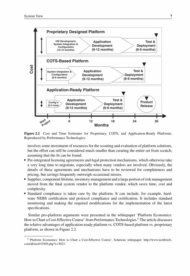
Figure 2.2 Cost and Time Estimates for Proprietary, COTS, and Application-Ready Platforms.Reproduced by Performance Technologies.
involves some investment of resources for the scouting and evaluation of platform solutions,but the effort can still be considered much smaller than creating the entire set from scratch,assuming that the fit can be found.
� Pre-integrated licensing agreements and legal protection mechanisms, which otherwise takea very long time to negotiate, especially when many vendors are involved. Obviously, thedetails of these agreements and mechanisms have to be reviewed for completeness andpricing, but savings frequently outweigh occasional misses.
� Supplier, component lifetime, inventory management and a large portion of risk managementmoved from the final system vendor to the platform vendor, which saves time, cost andcomplexity.
� Standard compliance is taken care by the platform. It can include, for example, hard-ware NEBS certification and protocol compliance and certification. It includes standardmonitoring and making the required modifications for the implementation of the latestspecifications.
Similar pro-platform arguments were presented in the whitepaper ‘Platform Economics:How to Chart a Cost-Effective Course’ from Performance Technologies.5 The article discussesthe relative advantages of application-ready platform vs. COTS-based platform vs. proprietaryplatform, as shown in Figure 2.2.
5 ‘Platform Economics: How to Chart a Cost-Effective Course‘, Solutions whitepaper: http://www.techbriefs.com/dl/ims032509.php?i=5023.
P1: OTA/XYZ P2: ABCc02 BLBK307-Bachmutsky August 30, 2010 20:15 Printer Name: Yet to Come
8 System Design for Telecommunication Gateways
There are a number of advantages that the whitepaper emphasizes:
� Hardware cost differential is small.This example cites a specific low-end chassis that is priced below $2000. There are a fewproblems with this argument. First of all, even $100 for a low-end product can become acritical factor. Second, the overhead is not only in the chassis, but also for every blade. Third,any standard has some limitations, such as size, power, connectors, etc.
� Smaller hidden integration costs.It is absolutely correct that an application-ready platform would have lower integration costs,but only based on the assumption that the selected platform fits the project 100%. In manyscenarios this is, unfortunately, not the case. The hardware designer can find out that there isno COTS blade available with the preferred functionality and/or component. The softwarearchitect might find that blades from different vendors support different operating systems, ordifferent distributions of the same operating system, or different middleware packages, or donot have a common interoperable software interface, or do not support the same capabilitiesand functionalities, and so on. All that will make hardware compatibility meaningless andwill bring similar hidden integration costs. The system architect can discover that there is aneed for additional integration that makes everything to look like one system with a singleIP address for management plane, and a single system for all neighbors on control and dataplanes. The biggest challenge might be to ensure that the platform is future-proof. Let us takethe example of ATCA chassis. Previously, the ATCA backplane had supported only 10 Gbpsswitch fabric, so it is impossible to add a 40 Gbps line card into a 10 Gbps chassis. Lately,ATCA had approved a new 40 Gbps IEEE 802.3ap 40GBase-KR compliant switch fabricand there are already products supporting it, but they will not support 100 Gbps line cardsthat will appear at some point of time down the road. All that means that there will alwaysbe some incompatibilities between different blades and vendors from both the hardware andsoftware points of view, bringing with it integration cost and potential product limitations.
� Operating system cost savings from Carrier Grade Linux licenses.This argument is even more problematic than the others, because it means that the platformsupplier also becomes the Linux distribution provider. It either creates additional Linuxdistribution, which is highly undesirable, or makes for an additional level of indirectionbetween the Linux distribution and the system integrator. If a bug in the Linux is discoveredor an additional feature is required, or a patch has to be applied, who would be responsiblefor it? What if different hardware vendors (and they can be future hardware vendors whodid not exist at the time of initial system creation) support different distributions or even thesame distribution, but different kernel versions? Somebody has to do the integration work.Of course, it can be the platform supplier, but this will work only when particular hardware isrequired by a large amount of the platform customers. It would mean that it is very difficult tobecome a leader in the industry, because the whole concept assumes that the same hardwareand software platform is used by many integrators and the only differentiator between theirproducts is in the application software. In some cases it is true, but it might be too narrowa view.
� Total profit analysis pointing to the claim that the platform cost is relatively small comparedto the total system cost.Similar to the previous argument, this assumes that the biggest differentiator is in thesoftware application layer, not the platform. Let us go back to the ATCA switch fabric

P1: OTA/XYZ P2: ABCc02 BLBK307-Bachmutsky August 30, 2010 20:15 Printer Name: Yet to Come
System View 9
example mentioned above. If the competitor had designed the proprietary system with100 Gbps switch fabric in mind and the existing platform cannot support it, there will be aneed to introduce a totally new platform with new hardware and potentially software vendorsand another integration effort. The competition might be able to simply introduce a newblade. Or the middleware integrated into the platform does not support a new feature X andthe competitor’s middleware is more advanced and introduced that feature. Either way, itcan provide a significant advantage for competitors that cannot be matched for some time.
Another problem with this argument is that it tries to justify the higher cost of the platformas compared to a proprietary solution. This should not be the case. The whole idea is thatthe COTS pre-integrated platform should come with a lower cost, because the developmentand integration efforts are divided between many platform customers. Otherwise, it pointsto the fact that the supply chain is too long, and the overall overhead is too high.
All that said, the benefits of the platform concept are undeniable, at least from the pointof view of time-to-market, and the counter-arguments above are not intended to criticize theplatform concept itself, but to provide a more balanced view of the issue.
Platforms become more and more popular with many projects. These platforms are some-times supplied by a third party and some large vendors create internal platform organizations inorder to share the same platform between multiple product lines. The importance of platformreuse has been emphasized by Cisco Systems’ architect, Chuck Byers, in his presentation atthe AdvancedTCA Summit 2008 (see Figure 2.3). The first recommendation is to create acommon platform. The second message is very clear: ‘Your goal should be 100% standardscompliance . . . Except when you can’t’.
Based on Cisco Systems’ thinking, the platform should integrate as much functionalityas possible: ‘Integrate multiple functions into single larger boxes . . . AdvancedTCA R© /MicroTCA R© can host multiple boxes from the network block diagram in one shelf . . .
Functions can still be partitioned across boards . . . Significant CAPEX savings because ele-ments like power cooling, and HPM aren’t duplicated . . . Significant OPEX savings’. On the
10
- MarketingSanta Clara, CA USAOctober 2008 - Architecture - HW Design - Core SW - App. SW - Integration - Factory - Support
Pro
ject
A
Pro
ject
B
Pro
ject
C
Pro
ject
D
Pro
ject
A
Pla
tform
Pro
ject
B
Pro
ject
C
Pro
ject
D
20
30
40
With Proprietary Platform(85 units of total development cost)
Dev
elop
men
t Cos
t (U
nits
)
10
Pro
ject
A
Pla
tform
Pro
ject
B
Pro
ject
C
Pro
ject
D
20
30
40
With Standard Platform(75 units of total development cost)
Dev
elop
men
t Cos
t (U
nits
)
10
20
30
40
Without Common Platform(100 units of total development cost)
Dev
elop
men
t Cos
t (U
nits
)
Figure 2.3 Use platforms to control total lifetime cost of ownership. Reproduced by Cisco.

P1: OTA/XYZ P2: ABCc02 BLBK307-Bachmutsky August 30, 2010 20:15 Printer Name: Yet to Come
10 System Design for Telecommunication Gateways
Figure 2.4 Experience with software reuse. Reproduced by permission of Embedded Systems Institute.
other hand, another recommendation from the same presentation at least partially contradictsthe one above: ‘Backplane topology follows application’. This partial contradiction occursbecause the backplane is shared between all applications, meaning that applications sharingthe same larger box have to be selected carefully to fit the same backplane profile requirements;not all applications can run together efficiently in the same platform. For example, Chuck By-ers recommends using dual-dual star backplanes for applications with control and data planeseparation (which is a trend in many recent telecommunications products developments), adual-star backplane for tree-like data processing, and a full-mesh backplane with significantpeer-to-peer traffic (see Section 3.4 for more information about the different backplane topolo-gies). It would be very difficult to follow Cisco Systems’ recommendation for even a singleapplication with separate data and control planes and a lot of peer-to-peer traffic, which wouldbe more complex for multiple different applications. Also, not every vendor would agree withCisco Systems that one large box is better than multiple smaller ones, see Section 3.1.4 forsome counter-arguments.
A very useful document about software reuse, which is an essential part of the platformthinking, was published by Gerrit Muller from the Embedded Systems Institute in The Nether-lands as a part of the Gaudi System Architecting project.6 The study included brainstormingwith the architects of many projects and illustrates that the results of the software reuse canvary from very bad to very good (see Figure 2.4).
As the article explains further: ‘The main problem with successful reuse strategies is thatthey work efficient as long as the external conditions evolve slowly. However breakthroughevents don’t fit well in the ongoing work which results in a poor response’. It is obvious thatsoftware reuse is one of the effective means for achieving the design goals; however the authoremphasizes a number of challenges:
� The technical challenge.As the article states correctly, ‘Most attempts to create a platform of reusable componentsfail due to the creation of overgeneric components’. Such overgeneric modules frequently
6 http://www.gaudisite.nl/info/SoftwareReuse.info.html; there is more about the project at http://www.gaudisite.nl/.

P1: OTA/XYZ P2: ABCc02 BLBK307-Bachmutsky August 30, 2010 20:15 Printer Name: Yet to Come
System View 11
create an unnecessarily large and inefficient (both in means of CPU time and memoryusage) code and cause more complex development, compromised readability and longercompetence transfer cycles; more difficult and less intuitive debugging (for example, whenfunction overrides are used), a larger amount of defects (usually, the number of defectsis proportional to the code size) and other negative effects. Also, code inefficiency cantrigger performance optimizations, which in turn make the code even less readable and moredifficult to debug and maintain. And so on, in vicious cycles.
Taking an example from telecommunication applications, let us imagine that the sameplatform is being reused for both network access and network core products (in routers itwould be access and core routers). Those familiar with these lines of products can respondimmediately that the scalability, performance, Quality-of-Service handling and even basicprotocols vary between access and core; and developing a single unified platform would beextremely inefficient. However, if multiple access and core products are planned, there is stilla significant reuse of components. In this particular scenario it might make sense to create ahierarchical reuse structure, where some components are reused by all access products, andthese components are replaced totally by another group of reusable components designedfor core networks.
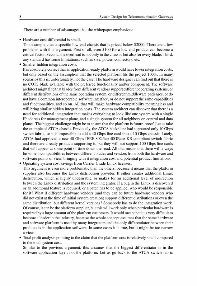
� The organizational challenge.The required change in the organizational hierarchy and decision making caused by thecommon platform should not be underestimated. As shown in Figure 2.5, a simple hierar-chical structure would have to be extended in operational, technical and commercial termsto include additional platform and component management layers. As usually happens,these additional layers can generate competition for control levels and control hierarchyand a classical ‘chicken and egg’ problem, which in this case can be stated as ‘what comesfirst – platform or product?’. Based on the fact that a single platform serves potentially manyproducts, the platform architect would argue that the platform is much more important andthus the product architecture has to be driven by the platform architecture; it all means thatthe platform comes first. The product architect would undoubtedly disagree, claiming thatthe platform has mostly internal added value, while the application is the real value-add thatsells and brings customers and sales; and thus the product architecture has to be optimizedbased on the target application and not the platform content; in short, the product comesfirst.
The article is very clear in that it would be very dangerous to follow ‘the platformcomes first’ principle and that the platform has to be only an enabler for the product,not the controlling element. On the other hand, it creates an enormous challenge for theplatform, because it has to enable many products, while at the same time avoiding theover-generalization described above.
Additional interaction between architects can create a feeling of competition within theglobal organization, dissatisfaction with decisions, overheads, a bi-directional architecturechallenge from ‘competing’ internal groups, conflict of interests and other issues. Some mayassume that it is much easier to solve all of these problems internally than with externalpartners and suppliers, but many experienced architects claim exactly the opposite: externalinterfaces can be driven by customer-supplier relationships, signed agreements and servicelevel commitments, while internal interfaces are much more sensitive and financials arebased on virtual money passing from pocket to pocket of the same large organization. Onthe other hand, the existence of all these critical and committed external documents means
P1: OTA/XYZ P2: ABCc02 BLBK307-Bachmutsky August 30, 2010 20:15 Printer Name: Yet to Come
12 System Design for Telecommunication Gateways
portfolio
operationalmanager
family
operationalmanager
projectleader
(single product)
projectleader
(subsystem)
developers
portfolio
architect
family
architect
product
architect
subsystem
architect
marketingmanager
family
marketingmanager
productmanager
entireportfolio
productfamily
singleproduct
subsystem
module
operational technical commercial
Organizational ChangeOrganizational Change
portfolio
operationalmanager
family
operationalmanager
projectleader
(single product)
projectleader
(subsystem)
subsystemdevelopers
entireportfolio
productfamily
singleproduct
sub-system
module
operational
projectleaderplatform
projectleader
(component)
componentdevelopers
marketingmanager
family
marketingmanager
productmanager
commercial
portfolio
architect
family
architect
product
architect
subsystem
architect
technical
platform
architect
component
architect
platformmanager
componentmanager
platform
component
Figure 2.5 Organizational change with common platform. Reproduced by permission of EmbeddedSystems Institute.
that the platform design and architecture phase with the third party supplier has to be thoughtthrough thoroughly in every tiny detail, because any deviation from the original specificationcan become very expensive. It is possible to say that the common platform developed by thethird party is more of a technical problem than the organizational one.
� Integration challenge.Reused platform product-specific software integration is another frequently underestimatedprocess. The challenge is especially significant when the architectures of application andplatform are different. One example of such a level of difference can be synchronous vs.

P1: OTA/XYZ P2: ABCc02 BLBK307-Bachmutsky August 30, 2010 20:15 Printer Name: Yet to Come
System View 13
asynchronous API calls. Platforms can be designed to fit one particular product applicationwell, but most others would potentially face serious problems. It is possible to create anApplication Abstraction Layer designed to smooth out these differences, but this additionallayer can affect performance and sometimes the behavior of the entire system. In the exampleof synchronous and asynchronous interfaces, there is a need to have not just a passive library,but also active threads facilitating inter-module communication with additional scheduling,timers and message queues, which increases the overall complexity and severely affectsperformance.
The article somewhat downplays the impact of the duplication between integrated mod-ules. While in many cases the immediate visible effect is only an additional code space, thereality can be much more complicated. First of all, even an additional code space can createa bottleneck in an L1 instruction cache. Second, duplicated mechanisms can use the sameshared and limited hardware resources. For instance, duplicated inter-process communica-tion messaging mechanisms could share common Direct Memory Access (DMA) hardwareblocks with a very limited number of channels, or shared physical interfaces (Ethernet, PCIExpress, etc.) with limited capacity, generating competition between these mechanisms. Oneof these mechanisms can assume that it owns the entire transport channel, which is no longertrue after integration. It also can build internal QoS algorithms for handling urgent and highpriority communication, but its behavior will be very different when another module is alsosending data through the same interface. There are multiple solutions for such contentions.One option is to virtualize or subdivide common hardware. Another option is to make mech-anisms aware of each other; which entails more duplication like that in the system and ismore complex to implement. It is possible to eliminate duplication as a root of the problem.Whatever the solution may be, it requires significant integration and verification.
The main point here is to prevent a situation described in the article as ‘the 95% readysyndrome, when the project members declare to at 95%, then actually more than half ofthe work still needs to be done’. It has to be clear that the engineers are not to be blamedfor the huge integration estimation miscalculation; it is the responsibility of the productand platform architects to plan and monitor the integration process closely. A highly uniqueresponsibility is placed on the shoulders of the platform architect, who sometimes in additionto his main job has to play a role of the other side, the product architect, for future products,which at the time of the integration design do not have explicit representation. It is not easyto be on both sides of the table at the same time, and the wrong decision can affect the costand time-to-market of many future products negatively.
� Platform evolution challenge.The working assumption should be that a platform is always a work-in-progress. It startsfrom delivering all of the required platform functionality in a number of stages becauseof the complexities of implementation and time-to-market requirements. It is followed byapplication modifications requiring additional features from the platform. Some modulesare included initially in a particular product application. At some subsequent point oftime these modules are required for other products as well, which causes the modules’transition from the application to the platform. The transition is usually accompanied byadditional integration, cleaning module external interfaces and defining additional platformAPI extensions, competence transfer between internal and/or external groups and in somecases even organizational changes with development, verification and maintenance teamschanging their reporting hierarchy. Sometimes the transition is actually in the opposite
P1: OTA/XYZ P2: ABCc02 BLBK307-Bachmutsky August 30, 2010 20:15 Printer Name: Yet to Come
14 System Design for Telecommunication Gateways
direction, from the platform to a product group, because of other products’ closure or futureproducts’ cancellation plans.
Gerrit Muller’s article provides one example of a platform, which in five years doubled itscode base and modified about a half of the original code. Our experience can be potentiallyless dramatic, nevertheless the changes over time are still substantial. In most cases thereis a significant effort to make these changes without affecting the platform APIs, but it isnot always possible. Sometimes the module supplier is changed and it is too difficult oreven impossible to keep the original interface; sometimes performance improvements causesignificant architecture shifts making initial APIs obsolete. All of these scenarios wouldtrigger corresponding modifications in either the Application Abstraction Layer, if suchexists, or even product application. The latter is undesirable, but nevertheless happens fromtime to time.
Gerrit Muller makes another valuable point in his article, the customers’ view. In most casesa platform serves only the internal customers, product application developers and architects(there are some cases when the platform is being exposed to third party partners or end-customers, but this is not typical in telecommunication systems). The end-customers areshielded by the corresponding product groups, and customers’ views and requirements aresomehow translated into the platform requirements. During that translation a great deal ofuseful information about market directions, end-customer long-term strategies, etc is lost. Aplatform can be forced to adopt a very short-term tactical viewpoint with visibility of one ortwo of the next releases. This would be a dangerous development in any organization, whensome parts of the company no longer have a clear end-customer focus. There is no doubt that itis significant overhead for platform architects to be involved in all end-user communications,especially when the number of products served by a common platform is large. However, theother extreme of no information is much worse. The organization has to develop processes tokeep the platform in the loop at all times.
2.3 System Verification
There are two ways to develop the system while taking care of the verification tasks: developfirst and test when ready; and test first and develop when it fails. Hardware developmentusually follows the first method and many software development projects are doing the same.An experienced developer adds enough interfaces and states to make sure that the functioncan be tested and is tested with all possible parameter variations; and that all the paths of thefunction with all of their permutations are exercised by the testing procedure. Such develop-ment takes longer, but results in a higher stability and fewer defects. Integrated debuggingcapabilities are also very critical. This includes extra statistics, debug registers, run-time codelocators, timestamps at different places in the software (for example, before and after theloop), etc. Software debugging features can be added using the multiple layers of a conditionalcompilation that are removed from the production version. However, when additional check(s)can be tolerated in the field, the debugging capability can be included using run-time variables,which simplifies the troubleshooting process.
In most cases, not all functions are ready for testing at the same time. Instead of delayingthe testing until everything is ready, it is better to simulate missing functions and their outputs.
P1: OTA/XYZ P2: ABCc02 BLBK307-Bachmutsky August 30, 2010 20:15 Printer Name: Yet to Come
System View 15
This brings into play the second method of the development process, which is testing first.The idea behind this method is that function development can be postponed (for instance, onlystub, or dummy, functions are added first) until at least one of the tests fails without it. Whenit happens, enough code is added to pass the test, and the cycle continues. Practically, thetesting code is written before the function implementation. The method allows for checkingthe design, thinking it through and modifying it as needed without starting a time-consumingdevelopment process; it increases the probability that there will be no need for a major re-design. On the other side, the iterative process can cause frequent interface changes and, asa result, modifications in many related functions. Therefore, it is recommended that eventhe initial stub functions include all known input and output parameters to leave interfacesunchanged for as long as possible. The entire process requires more weight to be given to thethe design phase and it also calls for strict developer’s discipline to ensure that there is noa single line of code without the existing failed test forcing the addition. One of immediateadvantages of using the technique is that the entire function is extensively and thoroughlytested with 100% code coverage. The second added value is that the testing can become anintegrated part of the documentation, because tests are created based not on the function code,but on the specification.
In addition to a decision about the selected test-aware development process, there is a needto define a number of additional tests:
� Unit test for new or modified modules. Unit tests are specified by the module developers andare reviewed and approved by the architects.
� System-wide functional tests for every feature. These tests are developed and maintained bysystem architects with support from verification and development engineers. Test automationshould be a key requirement.
� Sanity test for the system that verifies the few most critical system paths. Sanity tests are alsodeveloped and maintained by system architects. The idea behind the sanity test is to verifythe system quickly after the latest modification cycle. In many projects, the sanity testsare performed daily with automated build from the latest checked-in files and automatedload into the testing environment and automated test running. This process requires extremediscipline from the developers and formal and centralized check-in control in large andcomplex systems.
� The stability test is similar to the system-wide functional test, but is running in a separateand independent setup for an extended period of time (days, weeks or even months). Manyprojects do not release the system without passing the stability test.
� The scalability and sustained load tests verify system behavior with critical parametersreaching or exceeding the specified boundaries, such as a number of subscribers, sessions,addresses, flows and ports, data throughput, etc.
� Performance tests verify the system performance in a specified environment, such as thethroughput with back-to-back small packets or jumbo frames, traffic burst tolerance andsimilar parameters.
� Redundancy tests simulate the failure of various redundant components in the system (ifdesigned to work in the redundant configuration), including power supplies, fans, cores,ports and blades.
� Benchmarking compliance testing ensures the system’s competitive edge and supports mar-keting efforts.

P1: OTA/XYZ P2: ABCc02 BLBK307-Bachmutsky August 30, 2010 20:15 Printer Name: Yet to Come
16 System Design for Telecommunication Gateways
Additional pre-development stages may include system design modeling and testing thatcan be performed for very complex systems and multiple design options. Frequently, hard-ware can be simulated using function- or cycle-accurate simulators. It allows for commenc-ing software development before the actual hardware is available and also enables softwaredevelopment in a simulation environment without the need to have real hardware for everyengineer in the team.
P1: OTA/XYZ P2: ABCc03 BLBK307-Bachmutsky September 2, 2010 13:12 Printer Name: Yet to Come
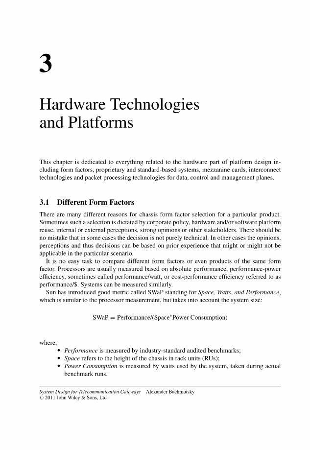
3Hardware Technologiesand Platforms
This chapter is dedicated to everything related to the hardware part of platform design in-cluding form factors, proprietary and standard-based systems, mezzanine cards, interconnecttechnologies and packet processing technologies for data, control and management planes.
3.1 Different Form Factors
There are many different reasons for chassis form factor selection for a particular product.Sometimes such a selection is dictated by corporate policy, hardware and/or software platformreuse, internal or external perceptions, strong opinions or other stakeholders. There should beno mistake that in some cases the decision is not purely technical. In other cases the opinions,perceptions and thus decisions can be based on prior experience that might or might not beapplicable in the particular scenario.
It is no easy task to compare different form factors or even products of the same formfactor. Processors are usually measured based on absolute performance, performance-powerefficiency, sometimes called performance/watt, or cost-performance efficiency referred to asperformance/$. Systems can be measured similarly.
Sun has introduced good metric called SWaP standing for Space, Watts, and Performance,which is similar to the processor measurement, but takes into account the system size:
SWaP = Performance/(Space∗Power Consumption)
where,� Performance is measured by industry-standard audited benchmarks;� Space refers to the height of the chassis in rack units (RUs);� Power Consumption is measured by watts used by the system, taken during actual
benchmark runs.
System Design for Telecommunication Gateways Alexander BachmutskyC© 2011 John Wiley & Sons, Ltd
17
P1: OTA/XYZ P2: ABCc03 BLBK307-Bachmutsky September 2, 2010 13:12 Printer Name: Yet to Come
18 System Design for Telecommunication Gateways
We would like to add its ‘cousin’ metric, called SPaC, which stands for Space, Performanceand Cost:
SPaC = Performance/(Space∗Cost)
where,� Cost is the total ownership cost (hardware, software, licenses, management, main-
tenance, electricity, air-conditioning, etc.) measured as an average yearly costcalculated throughout the intended product’s lifetime.
In some cases it is important to know the SWaP metric, because power can become a gatingfactor for a deployment as opposed to just an additional cost factor.
Performance is one of the most controversial parameters in the formulae above. Theproblem is to define a set of meaningful benchmarks applicable for multicore-basedtelecommunication systems. For example, the Standard Performance Evaluation Corporation(SPEC, http://www.spec.org; SPEC is sometimes defined mistakenly as System PerformanceEvaluation Corporation; this definition is incorrect, because SPEC in most cases does notcover the entire system performance) produces many benchmarks for CPUs (unfortunately,multicore coverage is not sufficient), graphics, workstations, Java, mail servers, network filesystem, power, server virtualization, Web servers, etc. Unfortunately, these tests cannot helpin comparing different telecom products. A better set of specifications is being developed bythe Embedded Microprocessor Benchmarking Consortium (EEMBC); a few benchmarks al-ready exist (NetMarkTM for networking applications, TeleMarkTM for telecommunication), butthey are still insufficient and are in the process of being extended. For example, TeleMarkTM
covers mostly DSP performance, which is not the only requirement (and sometimes is notrequired at all) for telecommunications equipment. See Section 3.5.6.3 for more benchmarkinginformation.
This chapter describes a number of proprietary and standard form factors while providingsome basic guidelines for a comparison between different form factors.
3.1.1 Proprietary 1U/2U/4U Chassis
The number of small- and medium-sized proprietary chassis is huge and it is impossible toreview all of them here. Therefore, products from three manufacturers (Advantech, Bivio andSun) are described with emphasis on the usage of the most advanced embedded multicoreprocessors on the market.
3.1.1.1 Advantech NCP-5120 with Dual Cavium Networks OCTEON Plus Processors
Advantech offers the 1U rackmount NEBS-designed pizza box network appliance NCP-5120(see Figure 3.1). It features dual 800 MHz Cavium Networks OCTEON Plus MIPS64 proces-sors (available with four to sixteen cores each, security and integrated hardware accelerationfor regular expression and compression/decompression functionality; see Section 3.5.6.2.3for more detail), one field-replaceable 2.5′′ SATA HDD accessible from the front panel, two

P1: OTA/XYZ P2: ABCc03 BLBK307-Bachmutsky September 2, 2010 13:12 Printer Name: Yet to Come
Hardware Technologies and Platforms 19
Figure 3.1 Advantech NCP-5120 with dual Cavium Networks OCTEON Plus multicore. Reproducedby Advantech.
RS-232 COM debugging ports on the back of the unit and one 10/100/1000Base-T Ethernetport for management purposes. The box can have up to twenty 100/1000Base-T Ethernetports with support for IEEE 802.1Q/P and IEEE 802.3ad Link Aggregation protocols, one64-bit/66 MHz PMC slot for additional interfaces, offload functions (for example, ATM SAR),additional storage, more processing capacity, etc.
For increased reliability, the platform includes dual AC or DC power supplies and field-replaceable hot-swappable fans designed to provide enough cooling capacity even when asingle fan fails, until its replacement.
Two OCTEON Plus processors are interconnected by 10 Gbps SPI 4.2 back-to-back linkswith support for up to sixteen logical channels for traffic separation or QoS enforcement.Processors share PCI-X bus allowing for a flat virtual memory model between processors andsimplified software programming. See the block diagram in Figure 3.2.
One unique capability of the NCP-5120 is the PCI-X bus between OCTEON Plus processors,because the PCI is not designed to serve two master processors. Advantech implementationmade it possible to have full access to peripheral devices from any processor and the capabilityof fully shared memory approach for communication between two processors. However,this fully shared memory approach, when applications access remote memory through amemory-mapped bus, can be slow and inefficient from the bus utilization point of view.The memory-mapped interface enables other architectures to be implemented on top of this
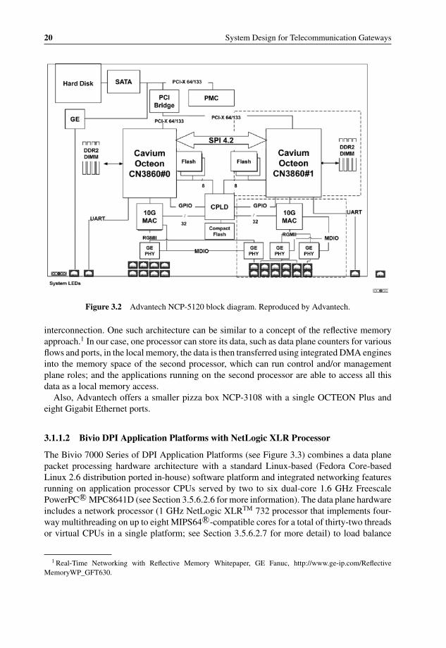
P1: OTA/XYZ P2: ABCc03 BLBK307-Bachmutsky September 2, 2010 13:12 Printer Name: Yet to Come
20 System Design for Telecommunication Gateways
Figure 3.2 Advantech NCP-5120 block diagram. Reproduced by Advantech.
interconnection. One such architecture can be similar to a concept of the reflective memoryapproach.1 In our case, one processor can store its data, such as data plane counters for variousflows and ports, in the local memory, the data is then transferred using integrated DMA enginesinto the memory space of the second processor, which can run control and/or managementplane roles; and the applications running on the second processor are able to access all thisdata as a local memory access.
Also, Advantech offers a smaller pizza box NCP-3108 with a single OCTEON Plus andeight Gigabit Ethernet ports.
3.1.1.2 Bivio DPI Application Platforms with NetLogic XLR Processor
The Bivio 7000 Series of DPI Application Platforms (see Figure 3.3) combines a data planepacket processing hardware architecture with a standard Linux-based (Fedora Core-basedLinux 2.6 distribution ported in-house) software platform and integrated networking featuresrunning on application processor CPUs served by two to six dual-core 1.6 GHz FreescalePowerPC R© MPC8641D (see Section 3.5.6.2.6 for more information). The data plane hardwareincludes a network processor (1 GHz NetLogic XLRTM 732 processor that implements four-way multithreading on up to eight MIPS64 R©-compatible cores for a total of thirty-two threadsor virtual CPUs in a single platform; see Section 3.5.6.2.7 for more detail) to load balance
1 Real-Time Networking with Reflective Memory Whitepaper, GE Fanuc, http://www.ge-ip.com/ReflectiveMemoryWP_GFT630.
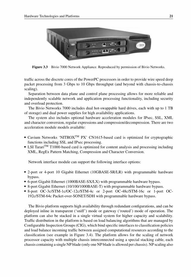
P1: OTA/XYZ P2: ABCc03 BLBK307-Bachmutsky September 2, 2010 13:12 Printer Name: Yet to Come
Hardware Technologies and Platforms 21
Figure 3.3 Bivio 7000 Network Appliance. Reproduced by permission of Bivio Networks.
traffic across the discrete cores of the PowerPC processors in order to provide wire speed deeppacket processing from 3 Gbps to 10 Gbps throughput (and beyond with chassis-to-chassisscaling).
Separation between data plane and control plane processing allows for more reliable andindependently scalable network and application processing functionality, including securityand overload protection.
The Bivio Networks 7000 includes dual hot-swappable hard drives, each with up to 1 TBof storage) and dual power supplies for high availability applications.
The system also includes optional hardware acceleration modules for IPsec, SSL, XMLand character conversion, regular expressions and compression/decompression. There are twoacceleration module models available:
� Cavium Networks ‘NITROXTM PX’ CN1615-based card is optimized for cryptographicfunctions including SSL and IPsec processing.
� LSI TarariTM T1000-based card is optimized for content analysis and processing includingXML, RegEx Pattern Matching, Compression and Character Conversion.
Network interface module can support the following interface options:
� 2-port or 4-port 10 Gigabit Ethernet (10GBASE-SR/LR) with programmable hardwarebypass.
� 6-port Gigabit Ethernet (1000BASE-SX/LX) with programmable hardware bypass.� 8-port Gigabit Ethernet (10/100/1000BASE-T) with programmable hardware bypass.� 8-port OC-3c/STM-1c/OC-12c/STM-4c or 2-port OC-48c/STM-16c or 1-port OC-
192c/STM-64c Packet-over-SONET/SDH with programmable hardware bypass.
The Bivio platform supports high availability through redundant configurations, and can bedeployed inline in transparent (‘sniff’) mode or gateway (‘routed’) mode of operation. Theplatform can also be stacked in a single virtual system for higher capacity and scalability.Traffic distribution in the platform is based on load balancing algorithms that are managed byConfigurable Inspection Groups (CIG), which bind specific interfaces to classification policiesand load balance incoming traffic between assigned computational resources according to theclassification (see example in Figure 3.4). The platform allows for the scaling of networkprocessor capacity with multiple chassis interconnected using a special stacking cable, eachchassis containing a single NP blade (only one NP blade is allowed per chassis). NP scaling also
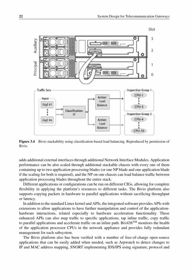
P1: OTA/XYZ P2: ABCc03 BLBK307-Bachmutsky September 2, 2010 13:12 Printer Name: Yet to Come
22 System Design for Telecommunication Gateways
Figure 3.4 Bivio stackability using classification-based load balancing. Reproduced by permission ofBivio.
adds additional external interfaces through additional Network Interface Modules. Applicationperformance can be also scaled through additional stackable chassis with every one of themcontaining up to two application processing blades (or one NP blade and one application bladeif the scaling for both is required), and the NP on one chassis can load balance traffic betweenapplication processing blades throughout the entire stack.
Different applications or configurations can be run on different CIGs, allowing for completeflexibility in applying the platform’s resources to different tasks. The Bivio platform alsosupports copying packets in hardware to parallel applications without sacrificing throughputor latency.
In addition to the standard Linux kernel and APIs, the integrated software provides APIs withextensions to allow applications to have further manipulation and control of the application-hardware interactions, related especially to hardware acceleration functionality. Theseenhanced APIs can also map traffic to specific applications, tap inline traffic, copy trafficto parallel applications and accelerate traffic on an inline path. BiviOSTM monitors the healthof the application processor CPUs in the network appliance and provides fully redundantmanagement for each subsystem.
The Bivio platform also has been verified with a number of free-of-charge open-sourceapplications that can be easily added when needed, such as Arpwatch to detect changes toIP and MAC address mapping, SNORT implementing IDS/IPS using signature, protocol and
P1: OTA/XYZ P2: ABCc03 BLBK307-Bachmutsky September 2, 2010 13:12 Printer Name: Yet to Come
Hardware Technologies and Platforms 23
anomaly based scanning, Squid implementing Web caching proxy for HTTP, HTTPS, FTP,etc., Argus for network activity monitoring, and others.
One interesting feature of the Bivio platform is that it can be configured to support either oftwo traffic modes: transparent mode or mixed mode. Transparent mode supports a traditionalinline, or ‘sniff’, behavior without the need for mirror-ports on a switch, because all networkinterfaces are configured with no IP address and the platform appears invisible, or like a wire,to the network devices on either side. Mixed mode allows configurations to be used wheresome interfaces are in transparent mode, and some (or even all) interfaces are in a gateway or‘routed’ mode. In gateway mode packets must be routed through the platform as if it was arouter and each interface is on a different subnet, has a unique IP address and is addressableindependently from outside the appliance.
Recently, Bivio also announced the carrier-grade Application Service Gateway (ASG) withup to 6 Gbps performance in the same small 2U form factor and scalable even higher inmulti-chassis configurations. These capabilities allow ASG to identify and enforce networkpolicies on a per-flow and per-subscriber basis. Bivio pre-integrated a number of services inthe ASG: Web content control with per-subscriber network-based parental control and contentfiltering; traffic enforcement designed to monitor, control and block Internet, P2P, IPTV andVoIP applications based on personalized subscriber profiles; service platform protection toshield networking infrastructure from Denial-of-Service attacks.
3.1.1.3 Sun Proprietary Chassis with UltraSPARC T2 and T2 Plus Processors
Sun offers many different products based on AMD R© or Intel R© multicore technologies, butthere are many other vendors with similar solutions. While Sun’s solutions still providesignificant differentiations (for example, some of them integrate the Sun’s Neptune 10 GigabitEthernet classification ASIC technology), they are not described here because they representthe more ‘usual’ technology (x86-based solutions for ATCA chassis are described in Section3.1.2.10.1). Instead, this chapter brings to the readers’ attention the more unique offerings,which are based on UltraSPARC R© T-series processors.
In 2005, Sun released Sun FireTM T1000 and T2000 servers, both based on theUltraSPARC R© T1 processor codenamed Niagara (see Section 3.5.6.2.9 for more detail).The Sun Fire T1000 server packages the UltraSPARC T1 processor into a 1U chassis typicallyconsuming 180 W of power and is targeted for various applications, such as Web servers,firewalls, proxy/caches and search farms. The Sun Fire T2000 server is packaged in a 2Uenclosure and includes greater redundancy, expandability (disk, I/O, and memory) and perfor-mance. Typical applications include virtualized and consolidated Web environments, JavaTM
application servers, enterprise application servers and online transaction processing databases.The Sun NetraTM T5220 (see on the left side in Figure 3.5 and block diagram on Figure
3.6) is a NEBS level-3 certified rackmount 2U pizza box build around the UltraSPARC T2SoC processor (see Section 3.5.6.2.9 for more information about the processor) running at 1.2GHz frequency with Integrated on-chip 10 Gigabit Ethernet and cryptographic acceleration(DES, 3DES, AES, RCA, SHA1, SHA256, MD5, RSA to 2048 key, ECC, CRC32). It supportsup to sixty-four simultaneous execution threads (eight cores with eight threads each), up to64 GB of memory utilizing sixteen 4 GB FB-DIMM slots, up to four 2.5′′ 146 GB SAS drives,(without DVD-RV),DVD-RW, four Gigabit Ethernet and two optional 10 Gigabit Ethernet

P1: OTA/XYZ P2: ABCc03 BLBK307-Bachmutsky September 2, 2010 13:12 Printer Name: Yet to Come
24 System Design for Telecommunication Gateways
Figure 3.5 T5440 (open boxes are shown), and SPARC Enterprise T5120. Reproduced by permissionof © 2009 Sun Microsystems, Inc.
networking ports with two XAUI cards installed and four PCI Express (two eight-lane andtwo four-lane). Three of the slots support low profile PCIe card only and one slot supportsfull length/full height PCIe card; and there are two PCI-X (one full-length/full-height, onehalf-length/full-height) expansion slots.
It is not surprising that in 2008 Continuous Computing had published the results of theTrillium multicore SIP application performance for the Sun Netra T5220, which achieved6000 calls per second, twice the best known previous testing, without a fully loaded CPU.There is no reference to any of the details of the previous testing, and it is difficult to say whichsystems were actually tested. We have to take into account that the Netra T5220 is twice aslarge as, for example, the Advantech NCP-5120. Nevertheless, the results are impressive andSun should get all the kudos for an excellent product.
It is important to mention that Sun Solaris on CMT processors comes pre-integrated witha virtualization layer, the hypervisor; it exists even when not in use. There is always somepenalty for virtualization and taking into account that Sun’s competition usually measuresperformance without virtualization (while in practice real products are using it), the achievedresults are even more impressive.
The Sun Netra T5440 (see on the right side in Figure 3.5 and the block diagram inFigure 3.8) practically doubles the T5220 with a 4U box and dual UltraSPARC T2 Plusprocessors. One significant advantage over other devices is that all multicore processors canrun in a cache-coherent single system mode with up to sixteen cores and 128 threads. Also, themechanical design is very good, clean and efficient for cooling and internal cable management.
The Sun SPARC EnterpriseTM T5140 platform (see Figure 3.7 and the block diagram inFigure 3.9) includes dual four-, six-, and eight-core 1.2-GHz or eight-core 1.4 GHz Ultra-SPARC T2 Plus processors with sixteen FB-DIMM slots for a total of up to 128 GB ofmemory, four Gigabit Ethernet ports and up to two 10 Gigabit Ethernet ports (as with allother products based on UltraSPARC T2 Plus processors, 10 Gigabit Ethernet ports are not in-cluded on-chip; therefore, Sun has added on the motherboard the Neptune ASIC with similar

P1: OTA/XYZ P2: ABCc03 BLBK307-Bachmutsky September 2, 2010 13:12 Printer Name: Yet to Come
Hardware Technologies and Platforms 25
Figure 3.6 Block diagram of the Sun SPARC Enterprise T5120/T5220. Reproduced by permission of© 2009 Sun Microsystems, Inc.
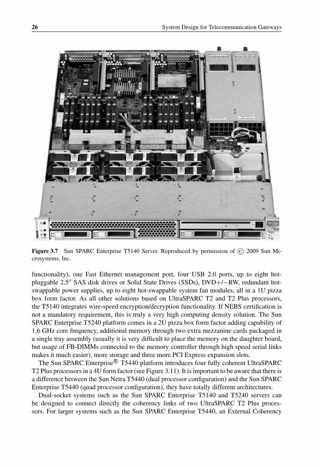
P1: OTA/XYZ P2: ABCc03 BLBK307-Bachmutsky September 2, 2010 13:12 Printer Name: Yet to Come
26 System Design for Telecommunication Gateways
Figure 3.7 Sun SPARC Enterprise T5140 Server. Reproduced by permission of © 2009 Sun Mi-crosystems, Inc.
functionality), one Fast Ethernet management port, four USB 2.0 ports, up to eight hot-pluggable 2.5′′ SAS disk drives or Solid State Drives (SSDs), DVD+/−RW, redundant hot-swappable power supplies, up to eight hot-swappable system fan modules, all in a 1U pizzabox form factor. As all other solutions based on UltraSPARC T2 and T2 Plus processors,the T5140 integrates wire-speed encryption/decryption functionality. If NEBS certification isnot a mandatory requirement, this is truly a very high computing density solution. The SunSPARC Enterprise T5240 platform comes in a 2U pizza box form factor adding capability of1.6 GHz core frequency, additional memory through two extra mezzanine cards packaged ina single tray assembly (usually it is very difficult to place the memory on the daughter board,but usage of FB-DIMMs connected to the memory controller through high speed serial linksmakes it much easier), more storage and three more PCI Express expansion slots.
The Sun SPARC Enterprise R© T5440 platform introduces four fully coherent UltraSPARCT2 Plus processors in a 4U form factor (see Figure 3.11). It is important to be aware that there isa difference between the Sun Netra T5440 (dual processor configuration) and the Sun SPARCEnterprise T5440 (quad processor configuration), they have totally different architectures.
Dual-socket systems such as the Sun SPARC Enterprise T5140 and T5240 servers canbe designed to connect directly the coherency links of two UltraSPARC T2 Plus proces-sors. For larger systems such as the Sun SPARC Enterprise T5440, an External Coherency
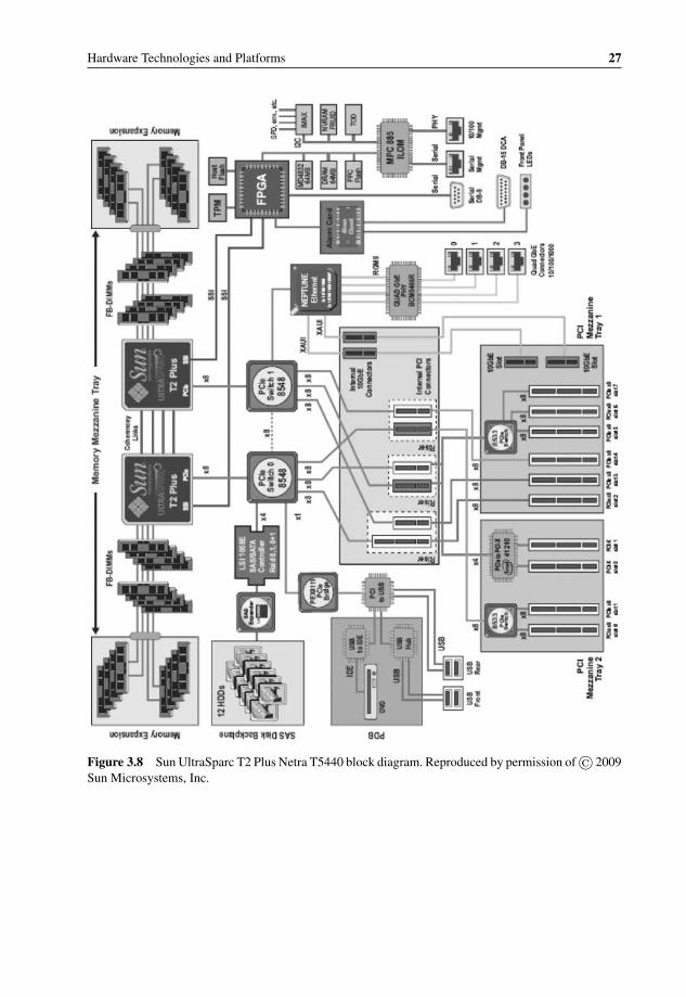
P1: OTA/XYZ P2: ABCc03 BLBK307-Bachmutsky September 2, 2010 13:12 Printer Name: Yet to Come
Hardware Technologies and Platforms 27
Figure 3.8 Sun UltraSparc T2 Plus Netra T5440 block diagram. Reproduced by permission of © 2009Sun Microsystems, Inc.

P1: OTA/XYZ P2: ABCc03 BLBK307-Bachmutsky September 2, 2010 13:12 Printer Name: Yet to Come
28 System Design for Telecommunication Gateways
Figure 3.9 Sun SPARC Enterprise T5140 and T5240 block diagram. Reproduced by permission of© 2009 Sun Microsystems, Inc.

P1: OTA/XYZ P2: ABCc03 BLBK307-Bachmutsky September 2, 2010 13:12 Printer Name: Yet to Come
Hardware Technologies and Platforms 29
Hub is required and each Sun SPARC Enterprise T5440 system includes four ExternalCoherency Hubs, with each connected to all four CPU Module sockets. The ExternalCoherency Hub is a four-port arbiter/switch implemented in a custom ASIC that interfaces tothe coherency control portion of the UltraSPARC T2 Plus processor and extends the cachehierarchy of a single UltraSPARC T2 Plus processor across up to four sockets and processors.The External Coherency Hub performs a number of functions, including:
� serializing requests to the same address for loads, stores and write-backs;� broadcasting snoops and aggregating responses;� providing flow control read and write requests to a processor;� providing ECC or parity protection.
When memory requests fail to hit a processor’s L2 cache, they are forwarded to the ExternalCoherency Hub. The hub fulfills these requests through a series of messages to multiple nodesin a system. The hub also functions as the single point of serialization for addresses withina coherency plane and enforces the ordering rules necessary to comply with the Total StoreOrdering consistency model. The External Coherency Hub is responsible for forwarding anode’s non-cacheable space and locations mapped to I/O devices on the PCI Express I/Ofabric attached to the destination node.
Sun also incorporates a great deal of the required software with all platforms and themajority of it is provided free of charge, which has to be considered seriously by manyprojects where software costs are frequently much higher than hardware costs. The operatingsystem is SolarisTM 10 Operating System (OS), with the ability to run SolarisTM 8 and9 applications within SolarisTM Containers. Platforms can integrate open-source, no-costvirtualization functionality using SunTM Logical Domains between operating system instances(LDoms, or virtual machines, scalable up to 64 in Netra T5220, up to 128 in the Sun SPARCEnterprise T5140, Netra T5440 and Sun SPARC Enterprise T5440), Solaris Containers withina single Solaris instance and Solaris ZFSTM file system for virtualized storage. Sun utilities canbe used during different phases of the product, from the technology selection and evaluation,through the development, to the deployment and maintenance (see Figure 3.10).
Provided across many of Sun’s products, the Integrated Lights Out Management serviceprocessor acts as a system controller for remote management and administration:
� Implements an IPMI 2.0 compliant services processor, providing IPMI management func-tions to the server’s firmware, OS and applications.
� Manages inventory and environmental controls, including CPU temperature conditions,hard drive presence, enclosure thermal conditions, fan speed and status, power supplystatus, voltage conditions, Solaris watchdog, boot time-outs and automatic restart events;and provides HTTPS/CLI/SNMP access to this data.
� Provides command line interface (CLI).� Facilitates downloading upgrades to all system firmware.� Allows the administrator to manage the server remotely, independent of the operating system
running on the platform and without interfering with any system activity.� Can send email alerts of hardware failures and warnings, as well as other events.� Runs independently from the main board, using the standby power, to function when the
server operating system goes offline, or when the system is powered off.

P1: OTA/XYZ P2: ABCc03 BLBK307-Bachmutsky September 2, 2010 13:12 Printer Name: Yet to Come
30 System Design for Telecommunication Gateways
Implementation Cycle
Application Selection
Cooltst•
Development
Sun Studio 12•
Tuning & Debugging
• ATS
Deployment
Cool Tuner•
Sun Application Porting •Assistant
GCC4SS (Compiling)•
BIT (Instrumenting)•
Cool Stack•Corestat•
Consolidation•
SPOT (Optimizing)•
Figure 3.10 Sun utilities for Netra platforms. Reproduced by permission of © 2009 Sun Microsystems,Inc.
Sun provides a very useful tool called the CoolThreadsTM Selection Tool, or cooltst. Thepurpose of cooltst is to help to determine the suitability of a Chip Multithreading (CMT)processor for a particular application. Its recommendations should help in making the decisionon how much effort to put into a feasibility study which might include porting, prototypingand/or performance measurement of the application, or workload. The recommendations arebased on two main criteria:
� Percentage of instructions which are using a floating point to optimize between UltraSPARCT1 and T2/T2 Plus processors. If the floating point content of the workload is high then theworkload may not be suitable for an UltraSPARC T1 processor which shares a single floatingpoint pipeline among all cores. High floating point content is not an issue for UltraSPARCT2 and T2 Plus processors.
� Parallelism. cooltest evaluates the degree of potential thread level parallelism, as measuredby the spread of CPU consumption among software threads; and instruction level parallelism,as measured by the cycles per instruction (CPI). A highly parallel workload may well exploitthe hardware parallelism of CMT processors to achieve high throughput. A workload withlow parallelism may not.
The result after cooltst analysis looks similar to the following:
Workload MeasurementsObserved system for 5 min
in intervals of 60 secCycles 24892691349Instructions 7766859467CPI 3.20FP instructions 6753668Emulated FP instructions 0FP Percentage 0.1%

P1: OTA/XYZ P2: ABCc03 BLBK307-Bachmutsky September 2, 2010 13:12 Printer Name: Yet to Come
Hardware Technologies and Platforms 31
Figure 3.11 Sun SPARC Enterprise T5440 block diagram. Reproduced by permission of © 2009 SunMicrosystems, Inc.

P1: OTA/XYZ P2: ABCc03 BLBK307-Bachmutsky September 2, 2010 13:12 Printer Name: Yet to Come
32 System Design for Telecommunication Gateways
The following applies to the measurement interval with the busiest single thread or process:
Peak thread utilization at 2007-10-01 20:41:15Corresponding file name 1191296475CPU utilization 24.5%Command XorgPID/LWPID 627/1Thread utilization 12%
Advice
Floating Point GREEN
Observed floating point content was not excessive for an UltraSPARC T1 processor. Floatingpoint content is not a limitation for UltraSPARC T2.
Parallelism GREENObserved parallelism was adequate for an UltraSPARC T1/T2
processor to be effectively utilized.
Another useful code evaluation tool is the SunTM Application Porting Assistant, whichperforms static source code analysis and code scanning to identify incompatible APIs betweenLinux and Solaris platforms and to simplify and speed up migration project estimation andengineering.
The Binary Improvement Tool (BIT) and the Simple Performance Optimization Tool (SPOT)are two additional Sun utilities used for code coverage analysis. The BIT provides instructionand call count data at runtime, helping to improve significantly developer productivity andapplication performance. The BIT does not require source code and works with both executa-bles and libraries. The SPOT helps deliver improved developer productivity by automating thegathering and reporting of code data.
Do not forget corestat utility for UltraSPARC T2/T2 Plus for CPU utilization analysis. Itdetects core frequency in run time and takes into account many T2 features, including twointeger pipelines per core (utilization per pipeline is reported), sixty-four hardware threads andthe dedicated Floating Point Unit (FPU) per core shared by all eight threads (FPU utilizationis reported together with integer utilization).
In many cases it may be useful to run the Sun Automatic Tuning and Troubleshooting System(ATS). ATS is a binary reoptimization and recompilation tool that can be used for tuning andtroubleshooting applications. It works by rebuilding the compiled Portable Executable Code(PEC) binary without the need for the original source code. For example, the ATS can find thecompiler options for the best performance; it can find the object file and the optimization flagthat is causing a runtime problem and rebuild the application using new compiler options.
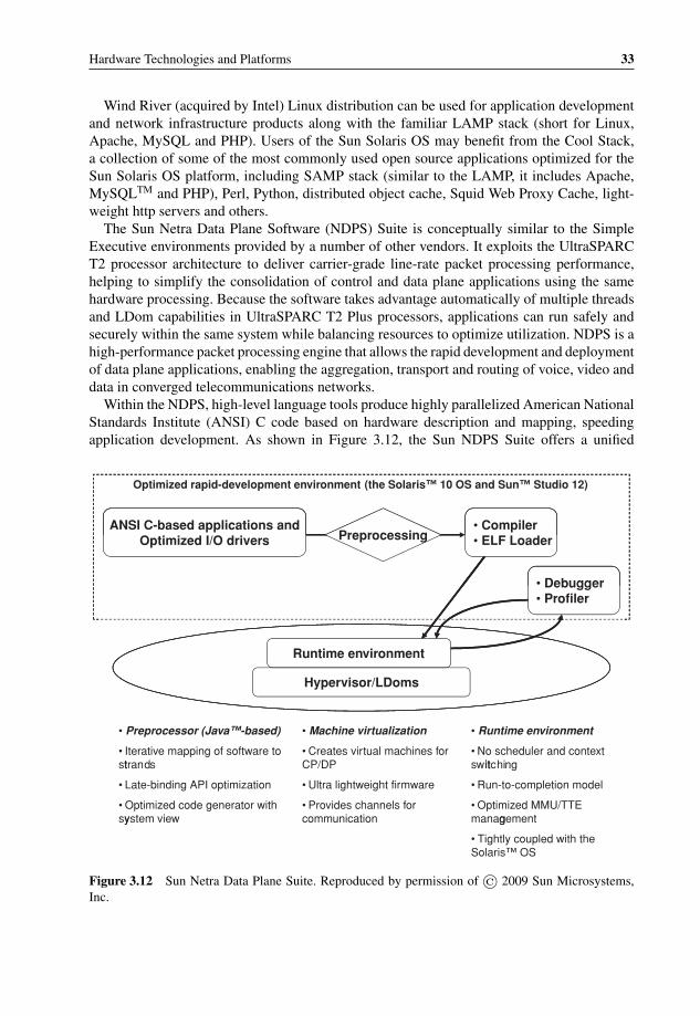
P1: OTA/XYZ P2: ABCc03 BLBK307-Bachmutsky September 2, 2010 13:12 Printer Name: Yet to Come
Hardware Technologies and Platforms 33
Wind River (acquired by Intel) Linux distribution can be used for application developmentand network infrastructure products along with the familiar LAMP stack (short for Linux,Apache, MySQL and PHP). Users of the Sun Solaris OS may benefit from the Cool Stack,a collection of some of the most commonly used open source applications optimized for theSun Solaris OS platform, including SAMP stack (similar to the LAMP, it includes Apache,MySQLTM and PHP), Perl, Python, distributed object cache, Squid Web Proxy Cache, light-weight http servers and others.
The Sun Netra Data Plane Software (NDPS) Suite is conceptually similar to the SimpleExecutive environments provided by a number of other vendors. It exploits the UltraSPARCT2 processor architecture to deliver carrier-grade line-rate packet processing performance,helping to simplify the consolidation of control and data plane applications using the samehardware processing. Because the software takes advantage automatically of multiple threadsand LDom capabilities in UltraSPARC T2 Plus processors, applications can run safely andsecurely within the same system while balancing resources to optimize utilization. NDPS is ahigh-performance packet processing engine that allows the rapid development and deploymentof data plane applications, enabling the aggregation, transport and routing of voice, video anddata in converged telecommunications networks.
Within the NDPS, high-level language tools produce highly parallelized American NationalStandards Institute (ANSI) C code based on hardware description and mapping, speedingapplication development. As shown in Figure 3.12, the Sun NDPS Suite offers a unified
Optimized rapid-development environment (the Solaris™ 10 OS and Sun™ Studio 12)
ANSI C-based applications andOptimized I/O drivers
• Compiler• ELF LoaderPreprocessing
• Debugger• Profiler
Runtime environment
Hypervisor/LDoms
• Preprocessor (Java™-based)
Iterative mapping of software to •dt
• Machine virtualization
Creates virtual machines for •CP/DP
• Runtime environment
No scheduler and context •hiitstran s
Late-binding API optimization•
Optimized code generator with •system view
Ultra lightweight firmware•
Provides channels for •communication
switc ng
Run-to-completion model•
Optimized MMU/TTE •managementy g
• Tightly coupled with the Solaris™ OS
Figure 3.12 Sun Netra Data Plane Suite. Reproduced by permission of © 2009 Sun Microsystems,Inc.

P1: OTA/XYZ P2: ABCc03 BLBK307-Bachmutsky September 2, 2010 13:12 Printer Name: Yet to Come
34 System Design for Telecommunication Gateways
LDom2LDom1
DataPlane
processing
ControlPlane
processing
DataPlane
processing
LWRTE LWRTEOS
Hypervisor Hypervisor
Strand Strand
Memory
Strand Strand
Memory
Strand Strand
Memory
Two common Data Plane deployments with UltraSPARC T1 and T2 processor architectures.
Figure 3.13 Sun virtualization with data plane processing. Reproduced by permission of © 2009 SunMicrosystems, Inc.
development environment, a lightweight runtime environment and virtualization based onhypervisor firmware and Logical Domains.
The lightweight runtime environment uses mainly static memory allocations, has noscheduler or interrupt handler and performs no context switching. Every thread runs to com-pletion without time slicing, making parallel execution extremely scalable. This enables upto 10 Gbps line-rate performance and linear scaling. It includes a standard IPC Control Planeinterface support.
The hypervisor firmware supports the ability to subdivide hardware CPU, memory, and I/Oresources to create virtual machines, LDoms helping to enable horizontal scaling of Data andControl Plane domains (see Figure 3.13; more information can be found in Section 4.4.1).
NDPS multithreaded profiling capabilities can help the user to optimize assignment ofthreads by determining the number of threads, the number of receive DMA channels to utilizeand the depth of the packet processing pipeline. In addition to standard optimizations, theNDPS profiler enables the collection of critical data during execution. Profiler API calls canbe inserted at desired places to start collecting or updating profiling data. The NDPS profilermakes use of the special counters and resources available in the hardware to collect requiredinformation. With the ability to profile CPU utilization, instruction counts, I/O wait times, datacache misses, secondary cache misses, memory queue, memory cycles and more, the NDPSprofiler enables simplified performance tuning efforts.
Also, a few reference applications (RLP, IPsec Gateway, IPv4/IPv6 forwarding, packet clas-sifier) are included. In most cases, more complete implementations from third party partnerswould have to be integrated.

P1: OTA/XYZ P2: ABCc03 BLBK307-Bachmutsky September 2, 2010 13:12 Printer Name: Yet to Come
Hardware Technologies and Platforms 35
Figure 3.14 Sun/Aricent WiMAX ASN-GW reference application. Reproduced by permission of ©2009 Sun Microsystems, Inc.
One example of NDPS usage is provided by Sun’s WiMAX ASN-GW reference design (seeFigure 3.14),2 where hardware and platform software is provided by Sun and the applicationlayer is provided by Aricent. It is important to emphasize that this is only the reference designthat has not been put into production.
3.1.2 Standard-Based Systems
Almost every major telecom equipment manufacturer has some kind of proprietary bladedsystem(s) in the portfolio. It is, of course, good practice to re-use these bladed systems asmuch as possible for multiple designs in order to recover the initial system development costs.Recovering that cost becomes especially difficult for high-end products sold in relatively lowquantities. The initial platform development overhead drives more and more developers towardstandard based and open specification platforms.
Also, the telecommunications industry is changing rapidly and the speed of that change isastonishing. A rapidly accelerating or decelerating local and global economy, technologicaldevelopments and other factors create major challenges. The market environment becomesmore and more competitive forcing both service providers and telecom equipment manufac-turers to reduce time-to-market while lowering the overall costs of research and development,maintenance, management and other components included in the total cost of ownership.
2 http://www.sun.com/servers/netra/docs/aricent_sol_brief.pdf.

P1: OTA/XYZ P2: ABCc03 BLBK307-Bachmutsky September 2, 2010 13:12 Printer Name: Yet to Come
36 System Design for Telecommunication Gateways
These requirements have created a significant push in the telecommunications sector towardsdevelopment of open standards and the integration of COTS components and even wholesubsystems. With such solutions in place, TEMs can minimize the development of proprietaryelements and concentrate on value-added services that create differentiation in the market.Chuck Byers from Cisco Systems addressed COTS usage in the abovementioned presentationat the Advanced TCA Summit in 2008 (see Chapter 1): ‘Use COTS HW and SW where feasible;custom where necessary. . . When you can’t find a suitable product on the COTS market, youcan design your own. . . In-house designs can have better intellectual property control, and cankeep trade secrets. . . In high volume, in-house designs can cost less. . . Continuously evaluateCOTS strategy. . . Use fully-integrated COTS boxes for the most time critical applications –customize with SW. Use COTS building blocks for prototypes. As needed, transition selectedelements from COTS to partner or in-house designs’.
One of the significant requirements for telecommunication systems (as opposed to theenterprise market) is Network Equipment Building Systems (NEBS) Level 3 compliance,which is a very stringent requirement obliging compliance with GR-63-CORE for physi-cal protection,3 GR-1089-CORE for electromagnetic compatibility and electrical safety4 andGR-78-CORE for physical design and manufacturing.5 In addition to significantly more ex-pensive NEBS-compliant design and manufacturing, the certification process is very complexand expensive making it very difficult for small companies to offer fully NEBS-3 compliantsolutions. This is the reason why many data sheets mention ‘designed for NEBS-3’ frequentlyinstead of ‘NEBS-3 certified’, and it is important to recognize the distinction between thesetwo terms.
This chapter reviews multiple PICMG specifications, including the latest AdvancedTelecommunications Architecture, and describes the different types of mezzanine cards.
3.1.2.1 PICMG Specifications
PCI is a high performance interconnect created by Intel in order to provide an interface betweencomponents (graphics, I/O, etc.) on the same board. The PCI interconnect was subsequentlymodified to become an external interface – PCI bus – that enabled the concept of the PCIboard.
The PCI Industrial Computer Manufacturers Group (PICMG) was established in 1994and develops common open PCI-based specifications. As with many other specifications,PICMG is developed by member companies from the industry. PICMG had released anumber of specifications divided into three series: Series 1 (PICMG1) – Passive Backplanespecifications; Series 2 (PICMG2) – CompactPCI specifications; and Series 3 (PICMG3) –Advanced Telecommunication Architecture (ATCA) specifications.
A comparison of available PICMG specifications can be represented by Table 3.1:6
3 http://telecom-info.telcordia.com/site-cgi/ido/newcust.pl?page=idosearch&docnum=GR-63.4 http://telecom-info.telcordia.com/site-cgi/ido/newcust.pl?page=idosearch&docnum=GR-1089.5 http://telecom-info.telcordia.com/ido/AUX/GR_78_TOC.i01.pdf.6 http://www.picmg.org.
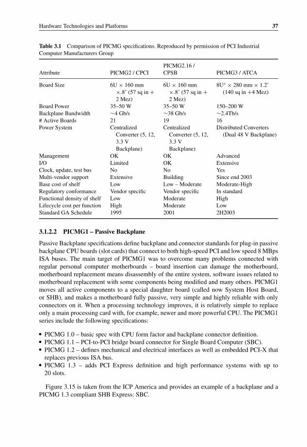
P1: OTA/XYZ P2: ABCc03 BLBK307-Bachmutsky September 2, 2010 13:12 Printer Name: Yet to Come
Hardware Technologies and Platforms 37
Table 3.1 Comparison of PICMG specifications. Reproduced by permission of PCI IndustrialComputer Manufacturers Group
Attribute PICMG2 / CPCIPICMG2.16 /CPSB PICMG3 / ATCA
Board Size 6U × 160 mm×.8’ (57 sq in +2 Mez)
6U × 160 mm×.8’ (57 sq in +2 Mez)
8U∗ × 280 mm × 1.2’(140 sq in +4 Mez)
Board Power 35–50 W 35–50 W 150–200 WBackplane Bandwidth ∼4 Gb/s ∼38 Gb/s ∼2.4Tb/s# Active Boards 21 19 16Power System Centralized
Converter (5, 12,3.3 VBackplane)
CentralizedConverter (5, 12,3.3 VBackplane)
Distributed Converters(Dual 48 V Backplane)
Management OK OK AdvancedI/O Limited OK ExtensiveClock, update, test bus No No YesMulti-vendor support Extensive Building Since end 2003Base cost of shelf Low Low – Moderate Moderate-HighRegulatory conformance Vendor specific Vendor specific In standardFunctional density of shelf Low Moderate HighLifecycle cost per function High Moderate LowStandard GA Schedule 1995 2001 2H2003
3.1.2.2 PICMG1 – Passive Backplane
Passive Backplane specifications define backplane and connector standards for plug-in passivebackplane CPU boards (slot cards) that connect to both high-speed PCI and low speed 8 MBpsISA buses. The main target of PICMG1 was to overcome many problems connected withregular personal computer motherboards – board insertion can damage the motherboard,motherboard replacement means disassembly of the entire system, software issues related tomotherboard replacement with some components being modified and many others. PICMG1moves all active components to a special daughter board (called now System Host Board,or SHB), and makes a motherboard fully passive, very simple and highly reliable with onlyconnectors on it. When a processing technology improves, it is relatively simple to replaceonly a main processing card with, for example, newer and more powerful CPU. The PICMG1series include the following specifications:
� PICMG 1.0 – basic spec with CPU form factor and backplane connector definition.� PICMG 1.1 – PCI-to-PCI bridge board connector for Single Board Computer (SBC).� PICMG 1.2 – defines mechanical and electrical interfaces as well as embedded PCI-X that
replaces previous ISA bus.� PICMG 1.3 – adds PCI Express definition and high performance systems with up to
20 slots.
Figure 3.15 is taken from the ICP America and provides an example of a backplane and aPICMG 1.3 compliant SHB Express: SBC.
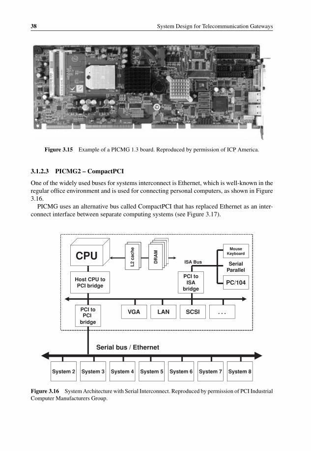
P1: OTA/XYZ P2: ABCc03 BLBK307-Bachmutsky September 2, 2010 13:12 Printer Name: Yet to Come
38 System Design for Telecommunication Gateways
Figure 3.15 Example of a PICMG 1.3 board. Reproduced by permission of ICP America.
3.1.2.3 PICMG2 – CompactPCI
One of the widely used buses for systems interconnect is Ethernet, which is well-known in theregular office environment and is used for connecting personal computers, as shown in Figure3.16.
PICMG uses an alternative bus called CompactPCI that has replaced Ethernet as an inter-connect interface between separate computing systems (see Figure 3.17).
Serial
MouseKeyboard
ISA BusCPU
L2
cach
e
DR
AM
DR
AM
DR
AM
Host CPU to PCI bridge
PCI to ISA
bridgePC/104
Parallel
PCI to PCI
VGA LAN SCSI . . .
bridge
Serial bus / Ethernet
System 2 System 3 System 4 System 5 System 6 System 7 System 8
L2
cach
e
DR
AM
Figure 3.16 System Architecture with Serial Interconnect. Reproduced by permission of PCI IndustrialComputer Manufacturers Group.

P1: OTA/XYZ P2: ABCc03 BLBK307-Bachmutsky September 2, 2010 13:12 Printer Name: Yet to Come
Hardware Technologies and Platforms 39
Serial
MouseKeyboard
ISA BusCPU
L2
cach
e
DR
AM
DR
AM
DR
AM
Host CPU to PCI bridge
PCI to ISA
bridgePC/104
Parallel
PCI to PCI
VGA LAN SCSI . . .
bridge
CompactPCI passive backplane
System 2 System 3 System 4 System 5 System 6 System 7 System 8
L2
cach
e
DR
AM
Figure 3.17 System Architecture with Parallel Interconnect. Reproduced by permission of PCI Indus-trial Computer Manufacturers Group.
While the original PCI parallel bus specification from the PCI Special Interest Group(PCI-SIG) is for 32-bit 33 MHz, it was extended later to 64-bit 66 MHz, with PCI-X 1.0 64-bit133 MHz and PCI-X 2.0 64-bit 266 MHZ and 533 MHz (the latter also adds error correction –ECC). Not all of the above options are implemented by PICMG.
One of the main advantages introduced in CompactPCI was a tight interconnect thatincludes memory mapping between the processing components as opposed to loose Eth-ernet interconnect implemented via a serial bus. On the other hand, Ethernet is one of themost efficient means of communication using messages. With the advantages and disadvan-tages of both schemes, PICMG2.16 revision introduced an architecture that combines both thetechnologies of serial and parallel connectivity, as shown in Figure 3.18.
There are multiple flavours of networks used by PICMG2 – Ethernet, Fibre ChannelTM,InfiniBandTM, StarFabricTM, PCI-Express, Advanced Switching (Advanced Switching wasdisbanded in 2007, but all specs were transferred to PICMG) and RapidIO R© interconnect. Forexample, PICMG2.16 has introduced 10/100/1000 Gigabit Ethernet implementation.
CompactPCI is an electrical superset of regular PCI, but with a different form factor withcorresponding cards in two sizes – 3U (100 mm by 160 mm) and 6U (160 mm by 233 mm).The signature feature of the specification is a high density low inductance and controlledimpedance 3U 220-pin or 6U 315-pin connector with the external metal shield.
The CompactPCI Express specification (called EXP.0) was released in 2005 and enablesusage of PCI Express technology (practically, serialized high speed PCI – and backwardscompatible to PCI – defined by PCI-SIG) with inclusion of up to four PCI Express linksand up to twenty-four 2.5 Gbps lanes providing total of 6 GBps bandwidth in each direction.

P1: OTA/XYZ P2: ABCc03 BLBK307-Bachmutsky September 2, 2010 13:12 Printer Name: Yet to Come
40 System Design for Telecommunication Gateways
System 1
Serial Interconnect
CompactPCI passive backplane
System 2 System 3 System 4 System 5 System 6 System 7 System 8
Figure 3.18 System Architecture with Serial and Parallel Interconnects. Reproduced by permission ofPCI Industrial Computer Manufacturers Group.
The specification is backward compatible with CompactPCI by including CompactPCI andhybrid slots with the latter capable of handling CompactPCI and CompactPCI Express cards.CompactPCI Express adds hot swap and enhanced system management capabilities that allowsfor the development of 99.999% highly available systems.
3.1.2.4 PICMG3 – Advanced TCA and CP-TA
ATCA continues the previous PICMG work for open source platforms, and incorporates thelatest technologies in the areas of interconnect, packet processing, reliability, manageability,power distribution, cooling and many others. The ATCA family of standards introduces newform factors for system cards, mezzanine cards and a chassis, or a shelf.
ATCA had defined the following very challenging targets for its specifications:
� Enable reduced development time and costs.� Support reduced total cost of ownership.� Apply to edge, core, transport, and data center.� Apply to wireless, wireline, and optical network elements.� Support a rich mix of processors, digital signal processors (DSPs), network processors
(NPUs), storage and input/output (I/O).� Integrate with multiple network elements.� Provide multi-protocol support for interfaces up to 40 Gbps.� Offer high levels of modularity and configurability.� Improve volumetric efficiency.� Improve power distribution and management.� Offer an advanced software infrastructure providing operating systems (OSs), appli-
cation programming interface (API) and Operation, Administration, Management, andProvisioning (OAM&P).
� Offer world-class element cost and operational expense.
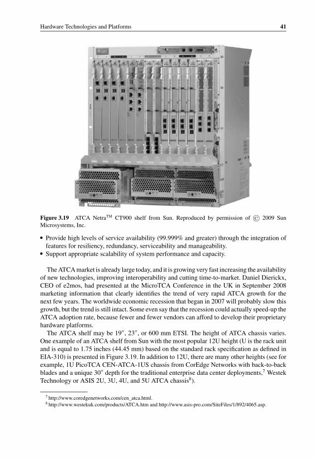
P1: OTA/XYZ P2: ABCc03 BLBK307-Bachmutsky September 2, 2010 13:12 Printer Name: Yet to Come
Hardware Technologies and Platforms 41
Figure 3.19 ATCA NetraTM CT900 shelf from Sun. Reproduced by permission of © 2009 SunMicrosystems, Inc.
� Provide high levels of service availability (99.999% and greater) through the integration offeatures for resiliency, redundancy, serviceability and manageability.
� Support appropriate scalability of system performance and capacity.
The ATCA market is already large today, and it is growing very fast increasing the availabilityof new technologies, improving interoperability and cutting time-to-market. Daniel Dierickx,CEO of e2mos, had presented at the MicroTCA Conference in the UK in September 2008marketing information that clearly identifies the trend of very rapid ATCA growth for thenext few years. The worldwide economic recession that began in 2007 will probably slow thisgrowth, but the trend is still intact. Some even say that the recession could actually speed-up theATCA adoption rate, because fewer and fewer vendors can afford to develop their proprietaryhardware platforms.
The ATCA shelf may be 19′′, 23′′, or 600 mm ETSI. The height of ATCA chassis varies.One example of an ATCA shelf from Sun with the most popular 12U height (U is the rack unitand is equal to 1.75 inches (44.45 mm) based on the standard rack specification as defined inEIA-310) is presented in Figure 3.19. In addition to 12U, there are many other heights (see forexample, 1U PicoTCA CEN-ATCA-1US chassis from CorEdge Networks with back-to-backblades and a unique 30′′ depth for the traditional enterprise data center deployments,7 WestekTechnology or ASIS 2U, 3U, 4U, and 5U ATCA chassis8).
7 http://www.coredgenetworks.com/cen_atca.html.8 http://www.westekuk.com/products/ATCA.htm and http://www.asis-pro.com/SiteFiles/1/892/4065.asp.
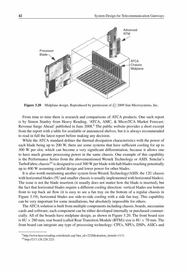
P1: OTA/XYZ P2: ABCc03 BLBK307-Bachmutsky September 2, 2010 13:12 Printer Name: Yet to Come
42 System Design for Telecommunication Gateways
ProcessorBlade
AdvancedRTM
ATCAChassisMidplane
Figure 3.20 Midplane design. Reproduced by permission of © 2009 Sun Microsystems, Inc.
From time to time there is research and comparisons of ATCA products. One such reportis by Simon Stanley from Heavy Reading, ‘ATCA, AMC, & MicroTCA Market Forecast:Revenue Surge Ahead’ published in June 2008.9 The public website provides a short excerptfrom the report with a table for available or announced shelves, but it is always recommendedto read in full the latest report before making any decision.
While the ATCA standard defines the thermal dissipation characteristics with the power ofeach blade being up to 200 W, there are some systems that have sufficient cooling for up to300 W per slot, which can become a very significant differentiation, because it allows oneto have much greater processing power in the same chassis. One example of this capabilityis the Performance Series from the abovementioned Westek Technology or ASIS. Simclar’sTurboFabric chassis10 is designed to cool 300 W per blade with hub blades reaching potentiallyup to 400 W assuming careful design and lower power for other blades.
It is also worth mentioning another system from Westek Technology/ASIS: the 12U chassiswith horizontal blades (5U and smaller chassis is usually implemented with horizontal blades).The issue is not the blade insertion (it usually does not matter how the blade is inserted), butthe fact that horizontal blades require a different cooling direction: vertical blades use bottomfront to top back air flow (it is easy to see a fan tray on the bottom of a regular chassis inFigure 3.19), horizontal blades use side-to-side cooling with a side fan tray. This capabilitycan be very important for some installations, but absolutely impossible for others.
The ATCA solution is built from multiple components including chassis, boards, mezzaninecards and software; each component can be either developed internally or purchased commer-cially. All of the boards have midplane design, as shown in Figure 3.20. The front board sizeis 8U × 280 mm, rear board (called Rear Transition Module (RTM)) size is 8U × 70 mm. Thefront board can integrate any type of processing technology: CPUs, NPUs, DSPs, ASICs and
9 http://www.heavyreading.com/details.asp?sku_id=2228&skuitem_itemid=1111.10 http://213.128.228.222/.

P1: OTA/XYZ P2: ABCc03 BLBK307-Bachmutsky September 2, 2010 13:12 Printer Name: Yet to Come
Hardware Technologies and Platforms 43
Figure 3.21 Caspian E1112 RTM. Reproduced by permission of Astute Networks.
FPGAs. The variety of different processing boards is so high and is expanding so rapidly thatit is practically impossible to provide a reference to the major ones; all of the processing tech-nologies can be found in the off-the-shelf ATCA blades, because major vendors view ATCAas a mandatory vehicle for the delivery of new technology. The front board can be a carrierboard for up to eight Advanced Mezzanine Cards (AMCs) depending on AMC size: Single-Width, Full-Height; Single-Width, Half-Height; Double-Width, Full-Height; Double-Width,Half-Height.
The idea of RTM is to expand the functionality of the front board. The RTM can be assimple as just interface expansion (for example, Sun Netra CP3200 ARTM-10 G with four10 Gbps and two 1 Gbps Ethernet ports) or more complex so as to include, for example, harddisks, as shown in Figure 3.21 and Figure 3.22 (both have a unique design with dual protrudingHDDs for easier maintenance).
Shelf Management is a very important part of the ATCA system. It adopts IntelligentPlatform Management Interface (IPMI) as a foundation for the entire functionality and isresponsible for:
� monitoring and controlling low-level aspects of ATCA boards and other Field ReplaceableUnits (FRUs);
� watching over system health, reporting anomalies, taking corrective action when needed;� retrieving inventory information and sensor readings;� receiving event reports and failure notifications from boards and other FRUs;� managing power, cooling and interconnect resources;� enabling visibility into a shelf for the Operations and Management (O&M) layer.
Figure 3.22 Sun Netra CP3200 ARTM-HDD with dual 2.5′′ HDD and additional interfaces. Repro-duced by permission of © 2009 Sun Microsystems, Inc.

P1: OTA/XYZ P2: ABCc03 BLBK307-Bachmutsky September 2, 2010 13:12 Printer Name: Yet to Come
44 System Design for Telecommunication Gateways
The ATCA shelf can have two shelf managers, active and standby, which have to be fromthe same vendor, because the protocol between them is not standardized. Each shelf manageris located on a separate board with shelf-dependent location (some vendors place them onthe top horizontally, some on the bottom horizontally and some put them vertically in thearea of the bottom fan tray). In addition, each board or independent FRU integrates an IPMController (IPMC) that acts as an agent or proxy for communication with the Shelf Manager.AMC carrier boards have integrated IPMC, but every AMC implements simplified ModuleManagement Controller (MMC) for lower cost and footprint; IPMC on the carrier board hasto represent every AMC as an independent FRU – up to eight IPMC ‘instances’ are required.
The PICMG 3.0 ATCA ‘core’ specification (its R3.0 was adopted in March 2008) definesthe following components: board, backplane and shelf mechanics; power distribution and theconnectivity for system management; multiple zones for connectors and their features: Zone1is used for power and management purposes, Zone2 is used for keying/alignment, synchronizedclocks, update channels (the interface between two adjacent ATCA slots; it is only enabledwhen boards with identical capabilities are on each end of the channel; it is mandatory for thebackplane, optional for blades), fabric interface (used mainly for data plane communicationbetween slots) and base interface (used mainly for control plane communication betweenslots). Shelf management represents a very significant portion of the core specification. Fabricdefinitions (coming in a variety of full mesh, star, dual-star and others, see Section 3.4) arespecified by subsidiary specifications:
� PICMG 3.1: specifies mandatory Ethernet and optional Fibre Channel fabric. As of thetime of writing, the specification is still in its original release R1.0 of 2003; work is goingon for R2.0 to incorporate 1000BASE-KX, 10GBASE-KX4 and 10/40GBASE-KR/4 fabricoptions.
The PICMG 3.1 Ethernet/Fibre Channel specification contains nine different interfacecombinations/options: one Gigabit Ethernet; two Gigabit Ethernet; four Gigabit Ethernet;one Gigabit Ethernet and one Fibre Channel; one Gigabit Ethernet and two Fibre Channel;two Gigabit Ethernet and two Fibre Channel; one Fibre Channel; two Fibre Channel; and one10 Gigabit Ethernet. It must be taken into account that the ATCA system can include multipleblades, each can support one or more of above options, creating integration problems: forexample, a blade that implements one Gigabit Ethernet interface will not work with a switchblade that implements one Fibre Channel interface.
For Ethernet, PICMG 3.1 borrowed a specification mainly from IEEE 802.3ae with someminor modifications; it will rely on the IEEE 802.3 standards family for further devel-opments. Ethernet is the most common and the cheapest interconnect, but even in thiscase there are multiple features where vendors differentiate themselves from the rest andthere is normally a price associated with additional features. One of the basic feature com-parisons and their importance is provided by J.P. Landry from Diversified Technology inthe whitepaper ‘Ethernet Protocols Primer for AdvancedTCA’.11 Of course, a feature’simportance depends on specific application needs. The whitepaper recommends includingVLAN support with optional expanded functionality using Generic Attribute RegistrationProtocol (GARP) and GARP VLAN Registration Protocol (GVRP) to allow automaticVLAN propagation through the network. It also recommends Multiple Spanning Tree
11 http://www.dtims.com/whitepapers/atca_protocols.pdf.
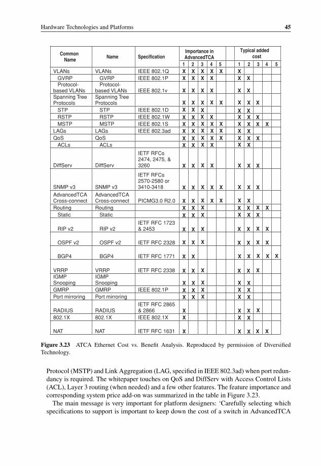
P1: OTA/XYZ P2: ABCc03 BLBK307-Bachmutsky September 2, 2010 13:12 Printer Name: Yet to Come
Hardware Technologies and Platforms 45
Importance in AdvancedTCA
Typical added costCommon
Name Specification Name 5 4 3 2 1 5 4 3 2 1
IEEE 802.1Q VLANs VLANs X X X X
X
X
X XX X
X XX XX X
XX
X
X XX X XX X X
X X X X X
X X X
X X XX X X
X X X
X X
X X
X
X X X
X X XX X XX
XX
X
X X
X X
X X X X X
X X X X X
X X X X
X X X X
X X X X
X X X X
X X X
X X X
X X X
X X
X
X X X
X X XX XX XX XX X
X
X X
X X
X XX XX X
X X
X X
X
X X X
X X X
X X
XIEEE 802.1P GVRP GVRP X X X X X X
Protocol-based VLANs
Protocol-IEEE 802.1v based VLANs X X X X X X
X X
Spanning Tree Protocols
Spanning Tree Protocols
IEEE 802.1D STP STP IEEE 802.1W RSTP RSTP IEEE 802.1S MSTP MSTP IEEE 802.3ad LAGs LAGs QoS QoS ACLs ACLs
DiffServ DiffServ
IETF RFCs 2474, 2475, & 3260
SNMP v3 SNMP v3
IETF RFCs 2570-2580 or 3410-3418
AdvancedTCA Cross-connect
AdvancedTCA Cross-connect PICMG3.0 R2.0
Routing Routing Static Static
RIP v2 RIP v2 IETF RFC 1723 & 2453
IETF RFC 2328 OSPF v2 OSPF v2
IETF RFC 1771 BGP4 BGP4
IETF RFC 2338 VRRP VRRP IGMPSnooping
IGMP Snooping IEEE 802.1P GMRP GMRP Port mirroring Port mirroring
RADIUS RADIUS IETF RFC 2865 & 2866 IEEE 802.1X 802.1X 802.1X
IETF RFC 1631 NAT NAT
Figure 3.23 ATCA Ethernet Cost vs. Benefit Analysis. Reproduced by permission of DiversifiedTechnology.
Protocol (MSTP) and Link Aggregation (LAG, specified in IEEE 802.3ad) when port redun-dancy is required. The whitepaper touches on QoS and DiffServ with Access Control Lists(ACL), Layer 3 routing (when needed) and a few other features. The feature importance andcorresponding system price add-on was summarized in the table in Figure 3.23.
The main message is very important for platform designers: ‘Carefully selecting whichspecifications to support is important to keep down the cost of a switch in AdvancedTCA
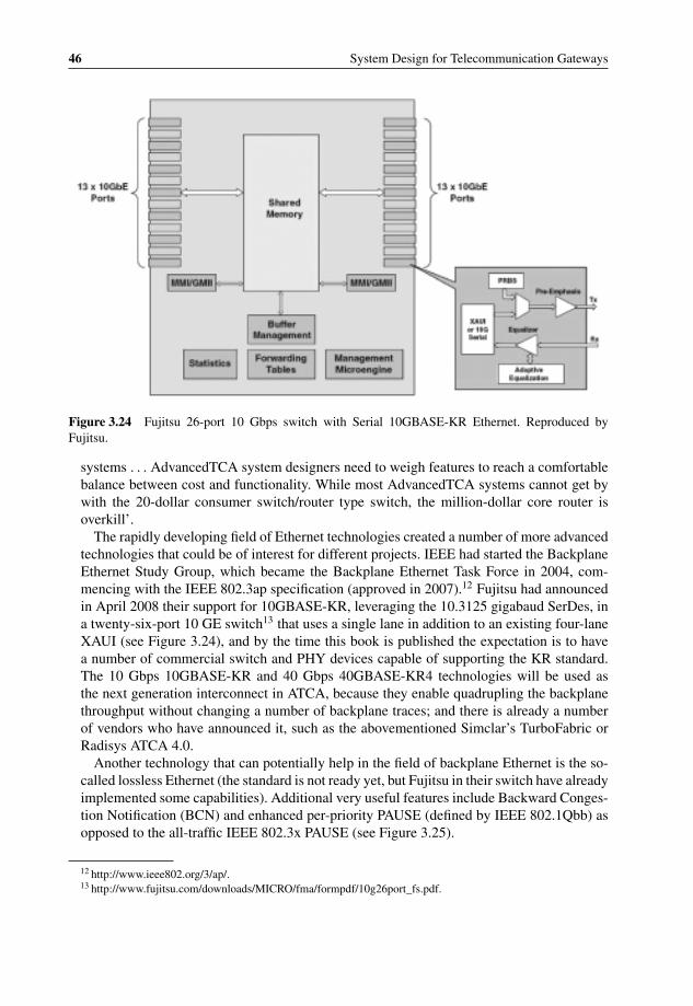
P1: OTA/XYZ P2: ABCc03 BLBK307-Bachmutsky September 2, 2010 13:12 Printer Name: Yet to Come
46 System Design for Telecommunication Gateways
Figure 3.24 Fujitsu 26-port 10 Gbps switch with Serial 10GBASE-KR Ethernet. Reproduced byFujitsu.
systems . . . AdvancedTCA system designers need to weigh features to reach a comfortablebalance between cost and functionality. While most AdvancedTCA systems cannot get bywith the 20-dollar consumer switch/router type switch, the million-dollar core router isoverkill’.
The rapidly developing field of Ethernet technologies created a number of more advancedtechnologies that could be of interest for different projects. IEEE had started the BackplaneEthernet Study Group, which became the Backplane Ethernet Task Force in 2004, com-mencing with the IEEE 802.3ap specification (approved in 2007).12 Fujitsu had announcedin April 2008 their support for 10GBASE-KR, leveraging the 10.3125 gigabaud SerDes, ina twenty-six-port 10 GE switch13 that uses a single lane in addition to an existing four-laneXAUI (see Figure 3.24), and by the time this book is published the expectation is to havea number of commercial switch and PHY devices capable of supporting the KR standard.The 10 Gbps 10GBASE-KR and 40 Gbps 40GBASE-KR4 technologies will be used asthe next generation interconnect in ATCA, because they enable quadrupling the backplanethroughput without changing a number of backplane traces; and there is already a numberof vendors who have announced it, such as the abovementioned Simclar’s TurboFabric orRadisys ATCA 4.0.
Another technology that can potentially help in the field of backplane Ethernet is the so-called lossless Ethernet (the standard is not ready yet, but Fujitsu in their switch have alreadyimplemented some capabilities). Additional very useful features include Backward Conges-tion Notification (BCN) and enhanced per-priority PAUSE (defined by IEEE 802.1Qbb) asopposed to the all-traffic IEEE 802.3x PAUSE (see Figure 3.25).
12 http://www.ieee802.org/3/ap/.13 http://www.fujitsu.com/downloads/MICRO/fma/formpdf/10g26port_fs.pdf.

P1: OTA/XYZ P2: ABCc03 BLBK307-Bachmutsky September 2, 2010 13:12 Printer Name: Yet to Come
Hardware Technologies and Platforms 47
VOICE
VOICE
VIDEO
VIDEO
INTERNET
VOICE VIDEO INTERNET
VOICE VIDEO INTERNET
INTERNET
PAUSE
MB86C69RBC MB86C69RBC
MB86C69RBC
MB86C69RBC
MB86C69RBCPRIORITY PAUSE
MB86C69RBC
TRADITIONAL PAUSE PRIORITY PAUSE
In a traditional PAUSE scenario all traffic transmission is halted by the sender for a specified period. Thus latency sensitive voice and video traffic are affected by
PAUSE
In a priority PAUSE scenario traffic transmission is halted for a specified period
of time on a specified priority. In this example “INTERNET” traffic which runs at a
lower priority is PAUSED while latency sensitive “VOICE” and “VIDEO” traffic is
uninterrupted
Figure 3.25 Priority PAUSE vs. Traditional PAUSE. Reproduced by Fujitsu.
Yet another approach for Ethernet-based traffic management is the emerging IEEE802.1Qaz standard which enforces bandwidth allocation and provides the flexibility tomanage traffic and bandwidth dynamically: when the traffic at a priority level does not useits full allocation, the IEEE 802.1Qaz ensures that other priorities are allowed to use thatbandwidth dynamically. Mellanox provides the functionality (in addition to the KR Ethernet,IEEE 802.1Qbb and IEEE 802.1Qau) in their ConnectX 10 Gbps Ethernet device14 as a partof the Data Center Ethernet (called the Converged Enhanced Ethernet) initiative driven byIEEE 802.1 Data Center Bridging Workgroup.
An additional potentially useful functionality to look for is the Internet Wide Area RDMAProtocol (iWARP) support. The idea is taken from protocols like InfiniBand (see PICMG3.2 later in this chapter for more information) that support RDMA natively; it reduces thelatency of packet processing, because the data is delivered directly into the memory of thedestination peer bypassing all intermediate layers (for example, OS kernel, sockets, etc.; seeFigure 3.26 and Figure 3.27 from the Neteffect (acquired by Intel) whitepaper15).
There are a number of published performance results for iWARP and its comparison withInfiniBand. One study was performed by Sandia National Laboratories and published inMay 2007 by Helen Chen, Noah Fischer, Matt Leininger, and Mitch Williams in SAND2007 – 2137 C report (presented at the OpenFabric Workshop in Sonoma, CA; published byChelsio16). Based on these results (see Figure 3.28), at least for some applications there is
14 http://www.mellanox.com/pdf/whitepapers/Mellanox_ConnectX_10GbE.pdf.15 http://www.download.intel.com/support/network/adapter/pro100/sb/understanding_iwarp.pdf.16 http://www.chelsio.com/nfs_over_rdma.html.

P1: OTA/XYZ P2: ABCc03 BLBK307-Bachmutsky September 2, 2010 13:12 Printer Name: Yet to Come
48 System Design for Telecommunication Gateways
Without RDMA With RDMA
application applicationapp buffer
applicationapp buffer
application
yrarbil O/Iyrarbil O/I
OS OS
user
server
context switch
OS bufferTCP/IP
OS OS
ecived ecived
kernel
serversoftware
adapter buffer
driver buffer
adapter bufferTCP/IP +RDMA
revirdrevird
I/O adapter
Standard Ethernet TCP/IP packet Ethernet TCP/IP packet with RDMA extension
Figure 3.26 TCP/IP with and without RDMA. Reproduced by Intel.
no big difference between performance and CPU utilization of iWARP and InfiniBand. TheInfiniBand Trade Association would probably disagree with such a conclusion.
The main component for iWARP is the Direct Data Placement (DDP) that enables a zero-copy data transfer. DDP is well-suited for the SCTP protocol, but it requires a Marker PDUAligned (MDP) framing in TCP, because TCP sends data with byte granularity as opposedto application data packet granularity.
It is likely that similar results can be achieved using InfiniBand over Ethernet (IBoE).However, as of the time of writing there are no off-the-shelf ATCA blades with iWARP orIBoE; if the feature is important, it might mean developing such a solution internally usingcomponents supporting one of these features.
Without iWARP With iWARP OS Bypass
application applicationI/O cmnd
applicationI/O cmnd
application
yrarbilO/IyrarbilO/I
OS OS
user
server
context switch
I/O cmnd I/O cmnd
cmndI/O
OS OS
devicedriver
devicedriver
kernel
softwareI/O cmnd
I/O cmnd
I/Odriver driver
I/O adapter I/O cmndiWARP-enabled Ethernet I/O adapteradapter
Figure 3.27 OS Bypass with iWARP. Reproduced by Intel.
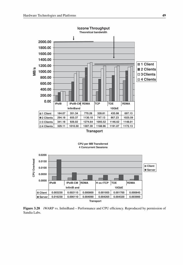
P1: OTA/XYZ P2: ABCc03 BLBK307-Bachmutsky September 2, 2010 13:12 Printer Name: Yet to Come
Hardware Technologies and Platforms 49
Iozone ThroughputTheoretical bandwidth
1800.00
2000.00
1000.00
1200.00
1400.00
1600.00
1800.00
M B
/s
1 Client2 Clients3
0.00
200.00
400.00
600.00
800.00
M Clients4 Clients
0.00
1 Client 697.13435.98328.81770.28351.34184.07
2 Clients 1025.59867.23747.131130.10655.37294.18
3 Clients 1148.011146.621093.521274.64926.02341.18
4 Clients 1172.131191.071188.961307.391010.50329.11
RDMATOETCPRDMAIPoIB-CMIPoIB
EbG01dnaBinifnI
Transport
CPU per MB Transferred 4 Concurrent Sessions
02000
0.0000
0.0050
0.0100
0.0150
0.0200
CP
U O
verh
ead
Client
Server
TOE RDMA
Transport
Client 0.0008450.0017000.0019550.0008000.0021150.003230
Server 0.0039000.0043200.0042650.0040900.0061100.016230
RDMA H os tTCP TOE RDMA
10GbEInfiniB and
IPoIB IPoIB-CM
Figure 3.28 iWARP vs. InfiniBand – Performance and CPU efficiency. Reproduced by permission ofSandia Labs.

P1: OTA/XYZ P2: ABCc03 BLBK307-Bachmutsky September 2, 2010 13:12 Printer Name: Yet to Come
50 System Design for Telecommunication Gateways
Currently, major technology developments are driven by data center applications, but thereis no doubt that they can be used very efficiently in the ATCA solutions that represent a minidata center in a single chassis.
Another fabric technology specified by PICMG 3.1 is the Fibre Channel, which is usedmainly for storage blades.
� PICMG 3.2: specifies InfiniBand fabric. As of the time of writing, the specification is stillin its original release R1.0 from 2003.
InfiniBand was developed in the late 1990s by the industry initiative called Next GenerationI/O (NGIO) led by Dell, Hitachi, Intel, NEC, Fujitsu Siemens and Sun. In parallel, therewas another initiative called Future I/O (FIO) led by IBM, Compaq, Adaptec, 3COM, CiscoSystems and Hewlett-Packard. In 1999 both specifications were merged into what is nowInfiniBand.
InfiniBand is a point-to-point bi-directional serial link; it has many signaling rates (startedfrom 2.5 Gbps full duplex, but is capable of going higher per lane) and multiple links canbe bonded together to achieve a higher bandwidth: 4x InfiniBand or even 12x InfiniBandwith a raw throughput of 120 Gbps assuming 10 Gbps lanes. However, a ‘real’ throughput islower because of 8 bit/10 bit encoding (8 bit of data is transmitted as 10 bit called a symbol)reaching a maximum of 96 Gbps data for the 12x InfiniBand.
InfiniBand is a very promising technology delivering high bandwidth low latency traffic.It supports a dynamic network topology enabling easy blade insertion or removal. It supportsthe QoS natively in several ways including credit-based flows, tight latency control, anda capability of up to sixteen virtual channels, or lanes, with a priority per virtual lane; onevirtual channel is reserved and is used for the InfiniBand management traffic. InfiniBandhas two main advantages over other solutions: a very low latency and native Remote DirectMemory Access (RDMA) support. The latter allows one to place information directly into thememory of the communication peer significantly cutting latency and processing overhead.
The InfiniBand Trade Association has published a bandwidth roadmap17 for InfiniBandperformance increase (see Figure 3.29).
There were times when InfiniBand was on every system vendor’s ‘radar’, there were evendiscussions about InfiniBand replacing PCI, but it never happened. Later, there was a periodwhen InfiniBand lost its popularity, but recently the technology is enjoying renewed interest.For instance, InfiniBand is used as the inter-chip interconnect in the IBM’s supercomputerRoadrunner.
ATCA InfiniBand implementation choices are very limited, which is disappointing, be-cause latency sensitive applications can really benefit from it. In 2005 Diversified Technologyannounced the availability of two blades incorporating InfiniBand, but not much has hap-pened since then and the products have been removed from their website. We could notfind any other and newer ATCA blades, but they might appear. For example, in November2008 Mellanox and Dell demonstrated at the SC08 show in Austin, Texas a 40 Gbps QuadData Rate (QDR) InfiniBand blade for the Dell PowerEdge M1000e-series Blade Enclosure,doubling existing InfiniBand solutions. In August 2009 Voltaire announced its 40 GbpsInfiniBand switch module for the IBM BladeCenter. Hopefully, a similar solution will beavailable for ATCA.
17 http://www.infinibandta.org/content/pages.php?pg=technology_overview.
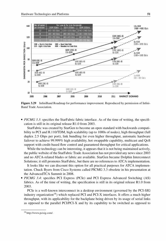
P1: OTA/XYZ P2: ABCc03 BLBK307-Bachmutsky September 2, 2010 13:12 Printer Name: Yet to Come
Hardware Technologies and Platforms 51
Figure 3.29 InfiniBand Roadmap for performance improvement. Reproduced by permission of Infini-Band Trade Association.
� PICMG 3.3: specifies the StarFabric fabric interface. As of the time of writing, the specifi-cation is still in its original release R1.0 from 2003.
StarFabric was created by StarGen to become an open standard with backwards compati-bility to PCI and H.110/TDM, high scalability (up to 1000s of nodes), high throughput (fullduplex 2.5 Gbps per port), link bundling for even higher throughput, automatic hardwarefailover to achieve 99.999% high availability, hot swappable capability, multicast and QoSsupport with credit-based flow control and guaranteed throughput for critical applications.
While the technology can be interesting, it appears that it is not being maintained actively,the public website of the StarFabric Trade Association has not provided any news since 2003and no ATCA-related blades or fabric are available. StarGen became Dolphin InterconnectSolutions; it still promotes StarFabric, but there are no references to ATCA implementation.
It looks like we can discount this option for all practical purposes for ATCA implemen-tation. Chuck Byers from Cisco Systems called PICMG 3.3 obsolete in his presentation atthe AdvancedTCA Summit in 2008.
� PICMG 3.4: specifies PCI Express (PCIe) and PCI Express Advanced Switching (AS)fabrics. As of the time of writing, the specification is still in its original release R1.0 from2003.
PCIe is a well-known interconnect in a desktop environment (governed by the PCI-SIGindustry organization18) which replaced PCI and PCI-X interfaces. It offers a much higherthroughput, with its applicability for the backplane being driven by its usage of serial linksas opposed to the parallel PCI/PCI-X and by its capability to be switched as opposed to
18 http://www.pcisig.com/.
P1: OTA/XYZ P2: ABCc03 BLBK307-Bachmutsky September 2, 2010 13:12 Printer Name: Yet to Come
52 System Design for Telecommunication Gateways
shared PCI bus and bridging. The PCIe standard lane speed is 2.5 Gbps (a faster PCIewith 5 Gbps lanes and additional functionality is already specified in PCIe Rev2, but isstill not supported by PICMG 3.4; PCIe Rev3 is already in the works with even faster 8Gbps lanes and a different encoding scheme. It will also add some useful features, such asthose often needed in the distributed environment, an atomic read-modify-write operation,multicast support and much more). It also enables bundling of up to thirty-two lanes ina single logical channel for high bandwidth interconnect. PCIe supports credit-based flowcontrol that ensures that the transmit starts only when the receiver can really accept the data.In addition, PCIe implements up to eight Virtual Channels (VC) and Traffic Classes (TC)mapped into VCs with the capability of multiple TCs being mapped into a single VC.
It is important to understand that with all of PCIe’s advantages, if PCIe is used notefficiently, it can cause significant performance bottlenecks. Craig Downing from TundraSemiconductor (acquired by Integrated Device Technology, IDT, in 2009) provides oneexample of such a performance challenge with PCIe-to-PCI bridge in his article ‘PCI expressbridging: optimizing PCI read performance’ published in Embedded Computing Design’sNovember 2008 issue.19 His example includes DSP on a PCIe Processor card connectedthrough the bridge to a PCI-based card with host CPU and memory that DSP tries to access(see Figure 3.30):
‘Introducing a PCIe bridge can cause a significant hit in performance. This read performancedegradation can occur through the following process:
◦ The DSP will initiate a read from the PC’s main memory. The bridge will latch the transactionand keep retrying until the bridge receives the data.
◦ The bridge will pre-fetch data from memory and store it in the internal buffer.◦ The DSP will read a portion of the data (one or two cache lines) and then disconnect, releasing
the PCI bus.◦ Once disconnected, the bridge will discard any remaining data in its buffer. With the next read
initiated by the DSP, the bridge will need to fetch the data again, retrying until the data is availablefor the DSP.
In this example, step 4 introduces significant delay between read transactions, which dramat-ically affects read performance. The impact on read performance that results from using aPCIe bridge can thus diminish system performance to a much greater degree than what canbe achieved using the PCI bus directly . . . PCIe bridges . . . incorporate a feature known asShort-Term Caching (STC) to help overcome this performance challenge. STC allows data tobe pre-fetched from the attached PCIe device during an initial PCI read cycle and temporar-ily stored in the bridge for quick turnaround during subsequent read cycles. Data that wouldbe read in subsequent reads is not immediately discarded when the requested device stops thetransaction.’
Advanced Switching interconnect technology (AS) was targeted to add more features ontop of basic PCIe:– Path routing in addition to memory mapping to circumvent host control for every transfer,
increase bus efficiency and lower latency. AS uses source-based routing for unicast packets(the exact path is specified by the packet source and is a part of the packet header; the
19 http://embedded-computing.com/pci-pci-read-performance.
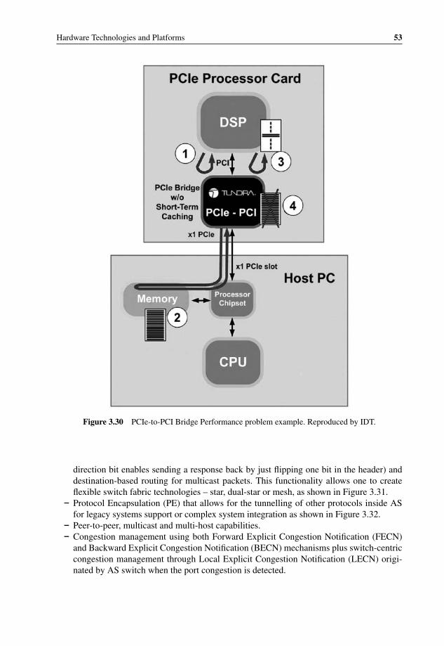
P1: OTA/XYZ P2: ABCc03 BLBK307-Bachmutsky September 2, 2010 13:12 Printer Name: Yet to Come
Hardware Technologies and Platforms 53
Figure 3.30 PCIe-to-PCI Bridge Performance problem example. Reproduced by IDT.
direction bit enables sending a response back by just flipping one bit in the header) anddestination-based routing for multicast packets. This functionality allows one to createflexible switch fabric technologies – star, dual-star or mesh, as shown in Figure 3.31.
– Protocol Encapsulation (PE) that allows for the tunnelling of other protocols inside ASfor legacy systems support or complex system integration as shown in Figure 3.32.
– Peer-to-peer, multicast and multi-host capabilities.– Congestion management using both Forward Explicit Congestion Notification (FECN)
and Backward Explicit Congestion Notification (BECN) mechanisms plus switch-centriccongestion management through Local Explicit Congestion Notification (LECN) origi-nated by AS switch when the port congestion is detected.
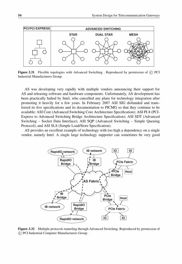
P1: OTA/XYZ P2: ABCc03 BLBK307-Bachmutsky September 2, 2010 13:12 Printer Name: Yet to Come
54 System Design for Telecommunication Gateways
MESHDUAL STARSTAR
PCI/PCI EXPRESS ADVANCED SWITCHING
Figure 3.31 Flexible topologies with Advanced Switching . Reproduced by permission of © PCIIndustrial Manufacturers Group.
AS was developing very rapidly with multiple vendors announcing their support forAS and releasing software and hardware components. Unfortunately, AS development hasbeen practically halted by Intel, who cancelled any plans for technology integration afterpromoting it heavily for a few years. In February 2007 ASI SIG disbanded and trans-ferred its five specifications and its documentation to PICMG so that they continue to beavailable: ASI Core (Advanced Switching Core Architecture Specification); ASI PI-8 (PCI-Express to Advanced Switching Bridge Architecture Specification); ASI SDT (AdvancedSwitching – Socket Data Interface); ASI SQP (Advanced Switching – Simple QueuingProtocol); and ASI SLS (Simple Load/Store Specification).
AS provides an excellent example of technology with too high a dependency on a singlevendor, namely Intel. A single large technology supporter can sometimes be very good
IOIORapidIO network IB network
PCIe FabricIB
BridgeRapidIO
IOIO
BridgeBridge
PCIeBridge
Hostg
AS Fabric
IBBridge PCIe
Bridge Host
IB networkRapidIOBridge PCIe Fabric
RapidIO network IO IO
Figure 3.32 Multiple protocols tunneling through Advanced Switching. Reproduced by permission of© PCI Industrial Computer Manufacturers Group.
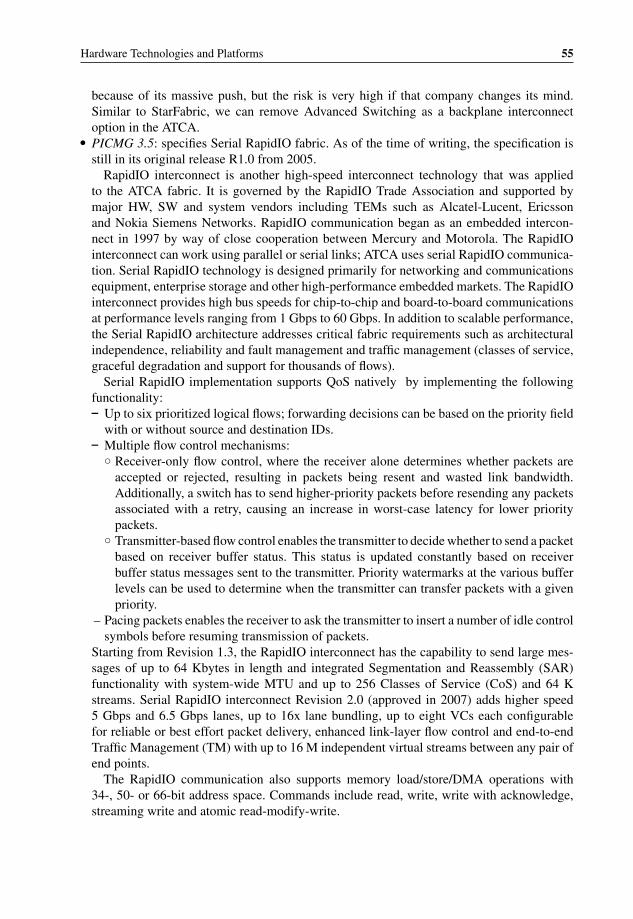
P1: OTA/XYZ P2: ABCc03 BLBK307-Bachmutsky September 2, 2010 13:12 Printer Name: Yet to Come
Hardware Technologies and Platforms 55
because of its massive push, but the risk is very high if that company changes its mind.Similar to StarFabric, we can remove Advanced Switching as a backplane interconnectoption in the ATCA.
� PICMG 3.5: specifies Serial RapidIO fabric. As of the time of writing, the specification isstill in its original release R1.0 from 2005.
RapidIO interconnect is another high-speed interconnect technology that was appliedto the ATCA fabric. It is governed by the RapidIO Trade Association and supported bymajor HW, SW and system vendors including TEMs such as Alcatel-Lucent, Ericssonand Nokia Siemens Networks. RapidIO communication began as an embedded intercon-nect in 1997 by way of close cooperation between Mercury and Motorola. The RapidIOinterconnect can work using parallel or serial links; ATCA uses serial RapidIO communica-tion. Serial RapidIO technology is designed primarily for networking and communicationsequipment, enterprise storage and other high-performance embedded markets. The RapidIOinterconnect provides high bus speeds for chip-to-chip and board-to-board communicationsat performance levels ranging from 1 Gbps to 60 Gbps. In addition to scalable performance,the Serial RapidIO architecture addresses critical fabric requirements such as architecturalindependence, reliability and fault management and traffic management (classes of service,graceful degradation and support for thousands of flows).
Serial RapidIO implementation supports QoS natively by implementing the followingfunctionality:– Up to six prioritized logical flows; forwarding decisions can be based on the priority field
with or without source and destination IDs.– Multiple flow control mechanisms:
◦ Receiver-only flow control, where the receiver alone determines whether packets areaccepted or rejected, resulting in packets being resent and wasted link bandwidth.Additionally, a switch has to send higher-priority packets before resending any packetsassociated with a retry, causing an increase in worst-case latency for lower prioritypackets.
◦ Transmitter-based flow control enables the transmitter to decide whether to send a packetbased on receiver buffer status. This status is updated constantly based on receiverbuffer status messages sent to the transmitter. Priority watermarks at the various bufferlevels can be used to determine when the transmitter can transfer packets with a givenpriority.
– Pacing packets enables the receiver to ask the transmitter to insert a number of idle controlsymbols before resuming transmission of packets.
Starting from Revision 1.3, the RapidIO interconnect has the capability to send large mes-sages of up to 64 Kbytes in length and integrated Segmentation and Reassembly (SAR)functionality with system-wide MTU and up to 256 Classes of Service (CoS) and 64 Kstreams. Serial RapidIO interconnect Revision 2.0 (approved in 2007) adds higher speed5 Gbps and 6.5 Gbps lanes, up to 16x lane bundling, up to eight VCs each configurablefor reliable or best effort packet delivery, enhanced link-layer flow control and end-to-endTraffic Management (TM) with up to 16 M independent virtual streams between any pair ofend points.
The RapidIO communication also supports memory load/store/DMA operations with34-, 50- or 66-bit address space. Commands include read, write, write with acknowledge,streaming write and atomic read-modify-write.

P1: OTA/XYZ P2: ABCc03 BLBK307-Bachmutsky September 2, 2010 13:12 Printer Name: Yet to Come
56 System Design for Telecommunication Gateways
SDRAM Flash
interface:Host
HostProcessor
HostInitializationSoftware DownloadConfiguration Signaling SupportNetwork Management
FromBSC/RNC
DSP DSP DSP DSP DSP
Ethernet/ ToTDM Bus
DSP DSP DSP DSP DSPAggregator
Logic
Ethernet/ATM
Bac
kpla
ne
ToPSTNSerial RapidIO Switch
Figure 3.33 Mobile Switching Center Architecture using Serial RapidIO interconnect. Reproduced bypermission of RapidIO Trade Association.
The RapidIO interconnect implements four mailboxes with up to four concurrent lettersfrom a single sender to a specific destination mailbox. In addition, it defines very short 1-and 2-bytes messages that are used as a doorbell mechanism.
These are indeed very powerful features that can serve many different applications. TheRapidIO Trade Association describes some applications in their overview;20 one is shown inFigure 3.33. A good description of RapidIO technology is also provided in [RapidIO-Fuller]but it is important to look beyond this book, because a great deal of development has takenplace since it was published.
The RapidIO specification presents a very aggressive roadmap for telecommunicationapplications (see Figure 3.34).21
Integrated Device Technology (IDT) became one of the leading Serial RapidIO componentvendors after the Tundra Semiconductor acquisition, offering multiple available solutions.22
For example, its third generation Serial RapidIO switch Tsi578 has 80 Gbps switchingperformance with 16 × 1 ports, or 8 × 4 ports or various × 1 and × 4 combinations.
Several Texas Instruments and Freescale DSPs support the RapidIO interconnect. Lately,multiple general purpose CPUs have started to add the Serial RapidIO solution to theirofferings. For instance, Freescale have integrated Serial RapidIO technology in their platformconcept of the eight-core QorIQTM P4080 Communications Processor,23 with the blockdiagram shown in Figure 3.35, and the quad-core P4040. Also, their existing dual-coreMPC8572E includes Serial RapidIO connectivity and based on this trend it looks likeFreescale will continue to support Serial RapidIO communication in their next generation
20 http://www.rapidio.org/education/documents/RapidIO_Overview-Apps_v07.pdf.21 http://www.rapidio.org/education/Roadmap/.22 http://www.tundra.com/products/rapidio-switches.23 http://www.freescale.com/webapp/sps/site/prod_summary.jsp?code=P4080.

P1: OTA/XYZ P2: ABCc03 BLBK307-Bachmutsky September 2, 2010 13:12 Printer Name: Yet to Come
Hardware Technologies and Platforms 57
RapidIO 1.0
RapidIO 1.2, 1.3, 2.03.0RapidIO
FutureTodayLegacy
Parallel – LVDS XAUISerial -
Serial – XAUI, CES1.25, 2.5, 3.12GBaud
5, 6.25GBaud1X, 2X, 4X, 8X, 16X
Dataplane Extensions
RapidIOSerial – CES
8, 10, 12GBaud?
- Multi-processor
- 10GBaud 4X backplanes- DSP and Processor Farms- Wireless 3G, WiMAX and LTE Systems- Video servers, IPTV, HDTV, Media GatewaysmicroTCA, AMC, PMC- DSP Cards
- CompactPCI- ATCA, VME- Military- Medical
-- VME, VSX, VPX systems- Storage/ Server Systems- RapidIO on Fibre
- 40GBaud+Backplanes- MulticoreProcessor Farms
- 2 .5G Wireless - WiMax Modem- SDRadio Growing into:
20GBaud 4X backplanes25 to 100GBaud interconnects
- Wireless 5G, LTE2, …
Dataplane extensions – Flow control, VoQ
Figure 3.34 RapidIO Technology and Application Roadmap. Reproduced by permission of RapidIOTrade Association.
products. A similar trend can be derived from AppliedMicro’s products and plans. Forexample, their existing 460GT processor supports RapidIO links, its main use being forDSP or inter-processor connectivity; although there are hints of its potential usage in thebackplane also, as shown in Figure 3.36.
Power Architecture® Encryption
RegExPattern
1024 KB Frontside L3 Cache
DDR2/DDR3SDRAM Controller
128 KB Backside L2 Cache
e500mc Core
32 KBL1 I-Cache
32 KBL1 D-Cache
EncryptionMatchingEngine
QueueBuffer
1024 KB Frontside L3 Cache
Enhanced
DDR2/DDR3SDRAM Controller
2 x DUART, 4 x I 2C,
CoreNet™ Coherency FabricQueue
ManagerBuffer
ManagerLocal Bus Controller
(eLBC)
Interrupt Control, GPIO, SD/MMC, SPI,
2 x USB 2.0/ULPI
Frame Manager Frame Manager
4 x 1 Gbps4 x 1 Gbps
On-Chip Network
RapidIO Message3 x PCIReal-Time
DebugEthernet Ethernet
1 x 10 Gbps
Ethernet Ethernet
18-lane SerDes
2 x SerialRapidIO®
2 x 4-ch.DMAUnit (RMU)Express®
Debug
Figure 3.35 Freescale QorIQ P4080 Communications Processor with integrated Serial RapidIO inter-connect. Copyright of Freescale Semiconductor, Inc. 2010, used by permission.
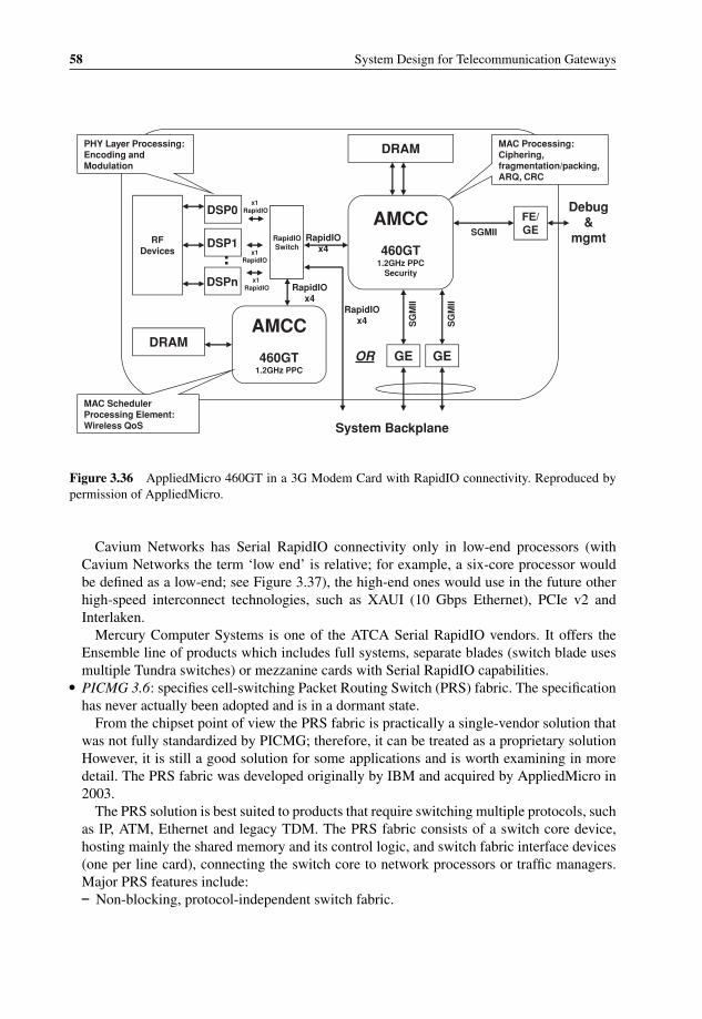
P1: OTA/XYZ P2: ABCc03 BLBK307-Bachmutsky September 2, 2010 13:12 Printer Name: Yet to Come
58 System Design for Telecommunication Gateways
DRAM MAC Processing:Ciphering,fragmentation/packing,
PHY Layer Processing:Encoding and Modulation
AMCC FE/GESGMII
Debug&
mgmt
ARQ, CRC
RapidIO RapidIO
DSP0
RF
x1RapidIO
460GT1.2GHz PPC
Security
gSwitch x4
Ra pidIO
RapidIOx4
DSP1
DSPn
RFDevices x1
RapidIO
x1RapidIO
AMCC
460GT1.2GHz PPC
DRAMGE GE
SG
MII
SG
MII
px4
OR
MAC SchedulerProcessing Element:Wireless QoS System Backplane
Figure 3.36 AppliedMicro 460GT in a 3G Modem Card with RapidIO connectivity. Reproduced bypermission of AppliedMicro.
Cavium Networks has Serial RapidIO connectivity only in low-end processors (withCavium Networks the term ‘low end’ is relative; for example, a six-core processor wouldbe defined as a low-end; see Figure 3.37), the high-end ones would use in the future otherhigh-speed interconnect technologies, such as XAUI (10 Gbps Ethernet), PCIe v2 andInterlaken.
Mercury Computer Systems is one of the ATCA Serial RapidIO vendors. It offers theEnsemble line of products which includes full systems, separate blades (switch blade usesmultiple Tundra switches) or mezzanine cards with Serial RapidIO capabilities.
� PICMG 3.6: specifies cell-switching Packet Routing Switch (PRS) fabric. The specificationhas never actually been adopted and is in a dormant state.
From the chipset point of view the PRS fabric is practically a single-vendor solution thatwas not fully standardized by PICMG; therefore, it can be treated as a proprietary solutionHowever, it is still a good solution for some applications and is worth examining in moredetail. The PRS fabric was developed originally by IBM and acquired by AppliedMicro in2003.
The PRS solution is best suited to products that require switching multiple protocols, suchas IP, ATM, Ethernet and legacy TDM. The PRS fabric consists of a switch core device,hosting mainly the shared memory and its control logic, and switch fabric interface devices(one per line card), connecting the switch core to network processors or traffic managers.Major PRS features include:– Non-blocking, protocol-independent switch fabric.

P1: OTA/XYZ P2: ABCc03 BLBK307-Bachmutsky September 2, 2010 13:12 Printer Name: Yet to Come
Hardware Technologies and Platforms 59
1x16bDDR3-1600
HFA Engines(DPI Engine)
FPA
DMA
Timers MemoryController
RAID 5/6
De-dup
ApplicationAcceleration
M
Compress/Decomp
CN63XX
2-6
DMA
Sec Vault PacketCrypto
Securityv3
MIPS64 r2
PacketCrypto
Securityv3
PowerOptimizer
Manager
PacketInput
cnMIPS IIcores
x4XAUI or 4x SGMII
PCIe v2/RIO4
37K Icache
32K Dcache
2K Write Buffer
37K Icache
32K Dcache
2K Write Buffer
x12Gen2SERDES
I/OBridge
x4
sRIO
PCIe v2/sRIO
x4
1x 72b DDR3 1600
PacketOutput L2 Cache
Memory Controller v2Misc I/O
Boot/Flash (NOR & NAND), CF, DDR3-160016GB max
16 GPIO, 2x UART, 2x I2C, 2x USB 2.0 w/PHY, 2 x RG/MII
Inte er Coreg
Hyper Access2MB Shared
MIPS64 r2Inte er Coreg
Figure 3.37 Cavium Networks OCTEON Plus CN63XX Block Diagram with Serial RapidIO ports.Reproduced by permission of Cavium Networks.
– 5 Gbps to 320 Gbps of full-duplex user bandwidth.– Multiple traffic scheduling QoS options with QoS enforcement at wire speed: strict traffic
priority scheduling, configurable credit table (to guarantee bandwidth to lower prioritytraffic) and credit table with fully preemptive highest traffic priority.
– Real-time traffic support (including TDM) thanks to the guaranteed precedence of timesensitive traffic over other traffic types; and the deterministic low latency, typically a fewmicroseconds’ transit delay for the high-priority traffic under worst case conditions (100%traffic load). Low latency is obtained through the use of a very high-speed, single-stage,shared memory.
– Full bandwidth multicast and broadcast with high QoS (low switching delay), thanks tothe powerful multicast and broadcast mechanism: single cell copy in shared memory,replication at sending with cell scheduling at different times for different output ports.
– End-to-end flow control: enables 100% utilization of the media bandwidth while main-taining QoS performance (low jitter).

P1: OTA/XYZ P2: ABCc03 BLBK307-Bachmutsky September 2, 2010 13:12 Printer Name: Yet to Come
60 System Design for Telecommunication Gateways
CardsLine
PHY 10G/OC-192 C192 or
Line Cards
HSS8 Links
HSS
ActiveSwitch
8x PRS Q-64G or
Q-80G
NP/TM C192XHSS
8 LinksSwitch Control
PHY2.5G/OC-48
NP/TM(nP37xx) C192 or
C192X
HSS8 Links
8x PRS Q 64G
Switch Control
PHY
PHY
2.5G/OC-48NP/TM
(nP37xx)
2.5G/OC-48NP/TM
HSS8 Links Protection
Switch
Q-64G or Q-80G
PHY
NP/TM (nP37xx)
2.5G/OC-48NP/TM
(nP37xx)
Switch Core (NxN)
Switch Fabric
Figure 3.38 32-Port Switch with Eight PRS Q-64G or PRS Q-80G. Reproduced by permission ofAppliedMicro.
– Switch board redundancy; designed to operate in redundant switch blade configurations:hot standby or traffic load sharing mode, with automatic takeover of the traffic of thefailing blade, and maintenance switchover between switch blades without any serviceinterruption and without any cell loss.An example of a system with PRS technology is shown in Figure 3.38. In practice, few off-
the shelf PRS implementations are available on the market. One possibility is to use RadisysPromentum ATCA-7010 blade that has a flexible fabric concept through a Fabric Interfacedaughter board that converts the SPI-4 interface to any other interface. AppliedMicro hassuch board for PRS implementations; the problem that the blade is outdated and does notprovide much flexibility for other options. It is possible to evaluate the technology usingan AppliedMicro evaluation board that includes nP3710 ATCA Line Cards and PRS ATCASwitch Cards. A block diagram for evaluation system is shown in Figure 3.39.
To summarize, PRS is a good option when cell switching (ATM, TDM) is required overthe switch fabric, but the solution will have to be built from scratch. Chuck Byers fromCisco Systems called PICMG 3.6 obsolete in his presentation at the Advanced TCA Summitin 2008.

P1: OTA/XYZ P2: ABCc03 BLBK307-Bachmutsky September 2, 2010 13:12 Printer Name: Yet to Come
Hardware Technologies and Platforms 61
# 1# 2 # 1
440 440440440440 440440440
PRS 80GPRS 80G
PRS ATCASwitch Cards
Backplane Zone2 Zone2
FIC FICFICFIC
FPGASPI-4.2 to CSIX
NPU PPC
FPGASPI-4.2 to CSIX
NPU PPC
FPGASPI-4.2 to CSIX
NPU PPC
FPGASPI-4.2 to CSIX
NPU PPC
Fabric Interface Daughter Card
nP
3710
AT
CA
L
ine
Car
d
Tigris
Evros
PHY
Tigris
Evros
PHY
Tigris
Evros
PHY
Tigris
Evros
PHYPMC’s# 14 # 3# 4# 5
Figure 3.39 AppliedMicro PRS Evaluation System. Reproduced by permission of AppliedMicro.
3.1.2.5 PCI Mezzanine Cards – PMC, PTMC. PrPMC, XMC
The PCI architecture is one of the most successful stories in computer platforms. It is beingdeployed in huge numbers and exists in almost every desktop and embedded product. It is builtas a family of backwards compatible specifications with more advanced capabilities as thetechnology becomes available – from PCI 32/33 (32-bit wide bus, 33 MHz clock frequency)to PCI-X 533 (64-bit wide bus, 533 MHz clock frequency). All of the speed generations ofthe PCI technology are interoperable. It is still possible to insert old 33 MHz devices into thefastest 533 MHz connection. The drawback, however, is that all of the devices on this bus willhave to work at the lowest common frequency, meaning that a single older device plugged incan affect the entire system performance significantly.
The newest PCI-X 533 can accommodate up to two 10 Gigabit Ethernet ports. The PCIarchitecture has a feature that is considered by some to be an advantage and by others adisadvantage – a parallel bus. PCI architects would insist that it is a great advantage to runa single pin per bit, because it enables one to achieve the same performance with a lowerfrequency. Sujith Arramreddy from Broadcom and Dwight Riley from Compaq claimed in thePCI-X 2.0 whitepaper24 that serial I/O technologies require a pair of differential signals forevery direction, bringing it to four wires per bit of data, and that a 4× wire efficiency advantagefor PCI-X compensates for the lower frequency. It is difficult to agree totally with this claim,
24 http://www.pcisig.com/specifications/pcix_20/pci_x_2dot0_white_paper.pdf.

P1: OTA/XYZ P2: ABCc03 BLBK307-Bachmutsky September 2, 2010 13:12 Printer Name: Yet to Come
62 System Design for Telecommunication Gateways
because authors ignore the fact that the parallel bus requires a large amount of pins whichbecome a significant bottleneck in the chip design and components routing on the board. Wedo see an opposite trend towards serializing all interfaces and this trend was applied to PCIwhen the PCIe specification was developed.
With all that said, PCI remains a very successful interconnect technology and the PCIMezzanine Cards (PMC) use it for connectivity to the main board. The PMC is defined inthe IEEE P1386 specification and has a size of 74 × 149 mm, large enough to host a varietyof highly dense interfaces or data/signal processing. The original IEEE 1386.1 specificationallows at most a 7.5 Watt power dissipation on PMC, because it assumes that the PMC can bemounted on top or near other components. The ANSI/VITA 20 standard added the ConductionCooled PCI Mezzanine Card (CCPMC) specification to provide better cooling conditions andhigher power dissipation per PMC. The ANSI/VITA 39 standard adds PCI-X support on topof the regular PCI.
The smaller version of PMC is called PC∗MIP;25 it has two sizes (90 × 47 mm and94 × 90 mm), uses the same 64-pin connectors as PMC with 32-bit PCI bus and is targetedfor small foot print applications.
The PCI Telecom Mezzanine Card (PTMC) standard is an extension of PMC; they sharethe same form-factor, but the PTMC adds interfaces to support telecom and voice-over-packetapplications: RMII, Ethernet PHY Management Interface, UTOPIA Level 1, UTOPIA Level2, POS-PHY Level 2 and ECTF H.110 interfaces.
Processor PMC (PrPMC) is another PMC extension defined in the ANSI/VITA 32 standardthat allows a processor on PMC to become a host or monarch. The idea is to allow PMCcarrying the processor to control the PCI bus. Such a design allows one to move the CPU fromthe base board to a mezzanine card in order to achieve more flexible and future-proof designs.However, PrPMC with CPU and memory usually dissipate much more than the original 7.5 W,meaning that the connectors to be used, the routing of components on the board and thermalsimulations have to be planned very carefully. An example of a 26 W PrPMC/PrXMC fromExtreme Engineering Solutions26 with conduction cooling (XPedite5301 with Freescale low-power version of the dual-core MPC8572E PowerQUICCTM III processor running at up to1.5 GHz, 2 GB memory, dual Gigabit Ethernet ports and up to 4x PCIe or Serial RapidIOlinks) is shown in Figure 3.40.
VITA 42 (XMC.0) has defined the XMC Switched Mezzanine Card so as to add highfrequency (more than 2.5 GHz) connectors in order to be able to connect to the switchfabric (the negative effect is the reduction of productive available space on the card). Forexample, VITA 42.1 (XMC.1) specifies 8-bit Parallel RapidIO implementation on XMC,VITA 42.2 (XMC.2) specifies one, four and eight lanes Serial RapidIO connectivity, VITA 42.3(XMC.3) adds one, two, four and eight lanes PCI Express, with full duplex data rates of up to2.5 GBps. Each XMC connector, primary and secondary, has these capabilities, but the sec-ondary connector can be used for an additional user I/O (for example, dual Gigabit Ethernetwhich is already standardized by VITA 42) instead of links for switch fabric connectivity. XMCadditional high-speed connectors are shown in Figure 3.41. The XMC standard promotes the
25 A good explanation of PC∗MIP with comparisons to other mezzanine card technologies (includingIndustry Pack Modules, M-Modules, PMC and PC∗MIP) can be found at http://www.groupipc.com/VPR/Articles/Mezzanines_comparison.htm.
26 http://www.xes-inc.com.

P1: OTA/XYZ P2: ABCc03 BLBK307-Bachmutsky September 2, 2010 13:12 Printer Name: Yet to Come
Hardware Technologies and Platforms 63
Temp Sensors
EEPROM GPIO
TransceiverRS-232 / RS-422 / RS-485
Co
nn
ecto
r
DDR2ECC SDRAM
Magnetics
GigabitEthernet
PHY
FreescaleMPC8572E
P16 P14
10/100/1000BASE-TUA
RT
s
Fro
nt
Pan
el C
DDR2ECC SDRAM
PCIe to PCI
BridgeProcessor
PCI
x1 PCIe
x4 PCI Express or Serial RapidIOLocal
NORFlash
NANDFlash
P15 P11 P12Local Bus
XPedite5301XPedite5301
Figure 3.40 XPedite5301 26 W PrPMC with low-power dual-core 1.5GHz MPC8572EPowerQUICCTM III. Reproduced by permission of Extreme Engineering Solutions.
development of carrier cards with dual function sites supporting both XMCs and PMCs; asmentioned above XPedite5301 is a good example of such an implementation. Therefore, basecards can support PMC and PrPMC modules today and enable a smooth transition to futureXMC technology upgrades.
It is possible to create a fabric-agnostic and future-proof XMC by using an FPGA withintegrated SerDes endpoints and fabric-specific firmware to adapt to any switch fabric.One example of such a solution is the TEK Microsystems’ JazzFiberTM card (refer tohttp://www.tekmicro.com for more detail).
P16
P13
P14
P16 Secondary
XMC
Each XMC Connector:6 x 19 pin array114 pins total
P11
P12
P15Primary
XMC
(component side)
Figure 3.41 XMC module with additional high speed connectors. Reproduced by Mercury ComputerSystems.
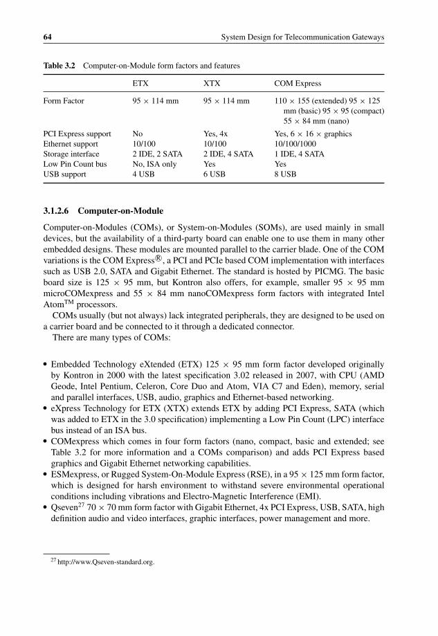
P1: OTA/XYZ P2: ABCc03 BLBK307-Bachmutsky September 2, 2010 13:12 Printer Name: Yet to Come
64 System Design for Telecommunication Gateways
Table 3.2 Computer-on-Module form factors and features
ETX XTX COM Express
Form Factor 95 × 114 mm 95 × 114 mm 110 × 155 (extended) 95 × 125mm (basic) 95 × 95 (compact)55 × 84 mm (nano)
PCI Express support No Yes, 4x Yes, 6 × 16 × graphicsEthernet support 10/100 10/100 10/100/1000Storage interface 2 IDE, 2 SATA 2 IDE, 4 SATA 1 IDE, 4 SATALow Pin Count bus No, ISA only Yes YesUSB support 4 USB 6 USB 8 USB
3.1.2.6 Computer-on-Module
Computer-on-Modules (COMs), or System-on-Modules (SOMs), are used mainly in smalldevices, but the availability of a third-party board can enable one to use them in many otherembedded designs. These modules are mounted parallel to the carrier blade. One of the COMvariations is the COM Express R©, a PCI and PCIe based COM implementation with interfacessuch as USB 2.0, SATA and Gigabit Ethernet. The standard is hosted by PICMG. The basicboard size is 125 × 95 mm, but Kontron also offers, for example, smaller 95 × 95 mmmicroCOMexpress and 55 × 84 mm nanoCOMexpress form factors with integrated IntelAtomTM processors.
COMs usually (but not always) lack integrated peripherals, they are designed to be used ona carrier board and be connected to it through a dedicated connector.
There are many types of COMs:
� Embedded Technology eXtended (ETX) 125 × 95 mm form factor developed originallyby Kontron in 2000 with the latest specification 3.02 released in 2007, with CPU (AMDGeode, Intel Pentium, Celeron, Core Duo and Atom, VIA C7 and Eden), memory, serialand parallel interfaces, USB, audio, graphics and Ethernet-based networking.
� eXpress Technology for ETX (XTX) extends ETX by adding PCI Express, SATA (whichwas added to ETX in the 3.0 specification) implementing a Low Pin Count (LPC) interfacebus instead of an ISA bus.
� COMexpress which comes in four form factors (nano, compact, basic and extended; seeTable 3.2 for more information and a COMs comparison) and adds PCI Express basedgraphics and Gigabit Ethernet networking capabilities.
� ESMexpress, or Rugged System-On-Module Express (RSE), in a 95 × 125 mm form factor,which is designed for harsh environment to withstand severe environmental operationalconditions including vibrations and Electro-Magnetic Interference (EMI).
� Qseven27 70 × 70 mm form factor with Gigabit Ethernet, 4x PCI Express, USB, SATA, highdefinition audio and video interfaces, graphic interfaces, power management and more.
27 http://www.Qseven-standard.org.
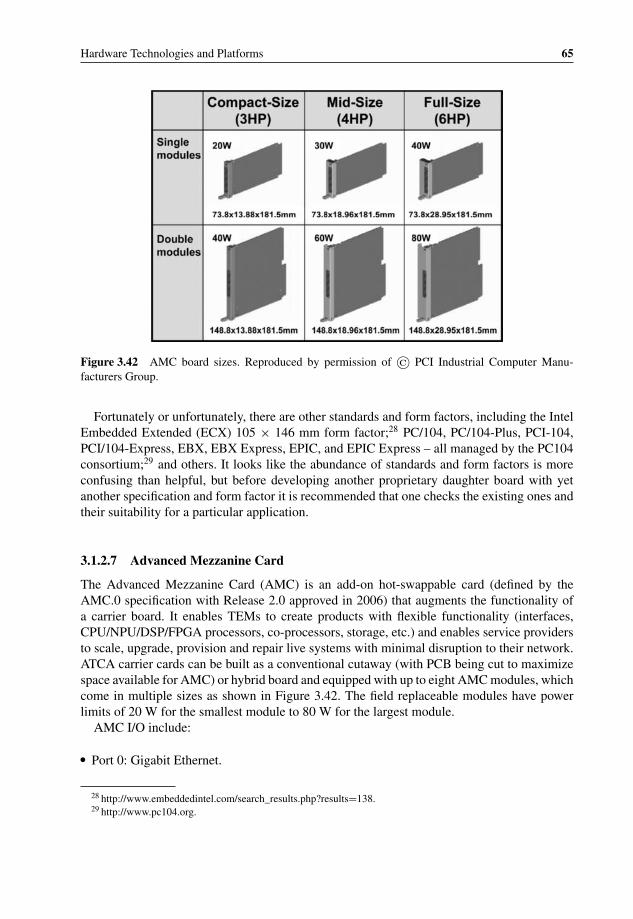
P1: OTA/XYZ P2: ABCc03 BLBK307-Bachmutsky September 2, 2010 13:12 Printer Name: Yet to Come
Hardware Technologies and Platforms 65
Figure 3.42 AMC board sizes. Reproduced by permission of © PCI Industrial Computer Manu-facturers Group.
Fortunately or unfortunately, there are other standards and form factors, including the IntelEmbedded Extended (ECX) 105 × 146 mm form factor;28 PC/104, PC/104-Plus, PCI-104,PCI/104-Express, EBX, EBX Express, EPIC, and EPIC Express – all managed by the PC104consortium;29 and others. It looks like the abundance of standards and form factors is moreconfusing than helpful, but before developing another proprietary daughter board with yetanother specification and form factor it is recommended that one checks the existing ones andtheir suitability for a particular application.
3.1.2.7 Advanced Mezzanine Card
The Advanced Mezzanine Card (AMC) is an add-on hot-swappable card (defined by theAMC.0 specification with Release 2.0 approved in 2006) that augments the functionality ofa carrier board. It enables TEMs to create products with flexible functionality (interfaces,CPU/NPU/DSP/FPGA processors, co-processors, storage, etc.) and enables service providersto scale, upgrade, provision and repair live systems with minimal disruption to their network.ATCA carrier cards can be built as a conventional cutaway (with PCB being cut to maximizespace available for AMC) or hybrid board and equipped with up to eight AMC modules, whichcome in multiple sizes as shown in Figure 3.42. The field replaceable modules have powerlimits of 20 W for the smallest module to 80 W for the largest module.
AMC I/O include:
� Port 0: Gigabit Ethernet.
28 http://www.embeddedintel.com/search_results.php?results=138.29 http://www.pc104.org.

P1: OTA/XYZ P2: ABCc03 BLBK307-Bachmutsky September 2, 2010 13:12 Printer Name: Yet to Come
66 System Design for Telecommunication Gateways
� Port 1: Gigabit Ethernet or PCIe (used as redundant pairs in High Reliability MicroTCAConfigurations).
� Port 2–3 : SATA, SAS or Fibre Channel.� Port 4–7: Fat Pipes XAUI, PCIe/AS or Serial RapidIO connection.� Port 8–11: Fat Pipes XAUI, PCIe/AS or Serial RapidIO connection (used as redundant pairs
in High Reliability MicroTCA Configurations).� Port 12–20: Extended Options.
AMCs are also a core of the PICMG’s MicroTCA specification. Instead of employing a car-rier board, MicroTCA configures AMCs directly on the backplane (refer to Section 3.1.2.8 formore detail). The ‘AMC direct to backplane’ concept extends the range of telecommunicationapplications for AMCs to low-end, cost-critical applications such as wireless base stations,wireless access units, or small-scale network elements.
A few secondary standard specifications describe port usage for different applications:
� AMC.1 defines port usage for PCI Express and Advanced Switching.� AMC.2 defines port usage for Ethernet.� AMC.3 defines port usage for Fibre Channel in storage applications.� AMC.4 defines port usage for Serial RapidIO communication.
The benefits of AMC over PMC are that AMC has features that qualify it for use with highthroughput 99.999% carrier grade availability: communication over high-performance serialinterconnects, including 1 and 10 Gigabit Ethernet, PCI Express and Serial RapidIO links.AMC modules are hot swappable, so they can be removed or inserted to and from the systemwhile the system is powered up, without incurring any data loss. Modules can be simplyremoved or inserted from the front of the device, without adversely affecting the operation ofthe carrier card or other mezzanine cards. Intelligent module management using IPMI enablesa hot-swap capability and guarantees compatibility between the ATCA carrier card and themodule using electronic keying.
In addition, AMCs are about 20% bigger and have a higher power envelope than PMCs andcan thus accommodate more chips and/or more powerful chips. Part of this area is reservedfor additional components such as an IPMI controller, but they still offer more functionaloptions than comparable PMCs. Initially, AMCs with similar functionality will often be moreexpensive than PMCs, but with economy of scale this will change.
In addition to ATCA and MicroTCA applications, AMCs have begun to appear latelyin many non-standard designs, enabling transition from a purely proprietary technology,using proprietary carrier boards with COTS AMCs, to 100% ATCA systems. As a resultof the compelling cost/benefit ratio, AMCs are designed into the new telecom equipment assmall field-replaceable units. They offer a standardized alternative to previously proprietaryreplaceable units, such as I/O interfaces, hard disks, or upgradeable CPUs.
Several manufacturers have introduced, for example, AMCs powered by the multicoreCavium Networks OCTEON Plus CN58xx processors (see Section 3.5.6.2.3 for more detailabout these processors). Kontron presented in February 2009 the AMCs with the CN5650processor: AM4204 (see Figure 3.43) with four Gigabit Ethernet ports to the front andsoftware-configurable interfaces to the fabric side (PCIe, 4× Gigabit Ethernet or XAUI);

P1: OTA/XYZ P2: ABCc03 BLBK307-Bachmutsky September 2, 2010 13:12 Printer Name: Yet to Come
Hardware Technologies and Platforms 67
Figure 3.43 AM4204 with Cavium Networks OCTEON Plus processor. Reproduced by permission ofKontron.
and AM4220 with dual 10 Gigabit Ethernet ports to the front and PCIe to the fabricside.
Another example of AMC is the Intel NetStructure R© WiMAX Baseband Card30 (see Figure3.44) powered by a 900 MHz Intel R© IXP2350 network processor with Open Base Sta-tion Architecture Initiative (OBSAI)-compliant RP-1, RP-2 and RP-3 interfaces, upgradeablesoftware-based WiMAX MAC and PHY implementations. It is radio frequency agnostic byemploying digital I/Q sampling between the WiMAX Baseband Card and radio equipment tosupport any spectral frequency in AMC.
Embedded Planet has announced the availability of EP8572 A,31 a single-width, full-heightAMC board integrating the 1.5 GHz Freescale PowerQUICC III MPC8572 processor withtwo e500 cores, up to 4 GB DDR2 in two SODIMMs, up to 256 MB of NOR flash and 4 GBof NAND flash, dual Gigabit Ethernet ports on the front panel and dual Gigabit Ethernet, PCIeand Serial RapidIO interfaces toward the switch fabric.
AMCs are also used for storage applications. A number of implementations can be found,for example, from SANBlaze Technologies.32
3.1.2.8 Micro-TCA
MicroTCA (written sometimes as uTCA or µTCA) is complementary to the ATCA. Insteadof focusing on high capacity high performance products, MicroTCA addresses cost sensitive
30 http://www.intel.com/design/telecom/products/cbp/amc/wimaxbbc/overview.htm.31 http://www.embeddedplanet.com/products/ep8572a.asp.32 http://www.sanblaze.com/embedded_storage/advancedMC_modules.php#15.

P1: OTA/XYZ P2: ABCc03 BLBK307-Bachmutsky September 2, 2010 13:12 Printer Name: Yet to Come
68 System Design for Telecommunication Gateways
Figure 3.44 Intel NetStructure R© WiMAX Baseband Card AMC. Reproduced by Intel.
and physically smaller devices with lower capacity, performance and potentially less stringentavailability requirements. The MicroTCA design goals are the following:
� Full conformance with the AMC.0 hot swappable module definition with support for allAMC form factors, relevant AMC.x interface specifications and ATCA shelf management.
� Favourable cost (including low start-up cost), size, and modularity.� Scalable backplane bandwidth in star, dual star and mesh topologies.� Modular and serviceable.� Support up to 300 mm nominal equipment depth and 19 in. nominal equipment width.� Cooling: 20–80 W per AMC.� Scalable system reliability: from .999 to .99999.
A MicroTCA block diagram is shown in Figure 3.45.To make AMCs interoperable between the ATCA Carrier board and MicroTCA shelf,
MicroTCA introduced the MicroTCA Carrier concept with a part of the MicroTCA shelfemulating the requirements of the carrier board (power delivery, interconnects, IPMI, etc.),defined in AMC.0 as to host up to twelve AMCs properly. That emulation includes backplane,connectors and other elements.
The MicroTCA Carrier Hub (MCH) combines the control and management infrastructure(including the MicroTCA Carrier Management Controller (MCMC) for IPMI functionality)and the interconnect fabric resources needed to support up to twelve AMCs into a singlemodule, which is the same size as the AMC. There could be a pair of MCHs to make thissolution suitable for high availability applications.
The MicroTCA shelf can include up to sixteen MicroTCA Carriers to support more thantwelve AMCs. For such a configuration, the shelf hosts a shelf management functionalitysimilar to ATCA. Shelf Manager also monitors and controls power supplies, fans and othercommon resources. However, the MicroTCA Shelf Manager functions are not exactly the sameas the functions of the ATCA Shelf Manager, because many of the functions performed by theShelf Manager in ATCA are performed by the Carrier Manager in MicroTCA. The followingis the list of some of these functions:

P1: OTA/XYZ P2: ABCc03 BLBK307-Bachmutsky September 2, 2010 13:12 Printer Name: Yet to Come
Hardware Technologies and Platforms 69
Cooling Unit #2
Cooling Unit #1
MicroTCA Carrier Hub (MCH) #2
MCMCMicroTCA Carrier Hub (MCH) #1
Power Module #N
Power Module #2
Power Module #1
MicroTCA Carrier
AirMover
EMMC
AirMover
MCMC
CommonOptionsFabric
FatPipe
Fabric
Clock
MCMC
CommonO ti
FatPi
Cl
FatPipe
Fabric
Clock
FatPipe
Fabric
Cloc
Power Module #1
PayloadPower
Converter
MgmtPower
Converter
EMMC
EMMC
kOptionsFabric
PipeFabric
ock
Fabric ckEMMC
PowerControl
JSM
AM
AM
AM
AM
AM
AM
AM
AM
AM
AM
AM
AM
Backplane Interconnect
C#1
C#2
C#3
C#4
C#5
C#6
C#7
C#8
C#9
C#10
C#11
C#12
Figure 3.45 MicroTCA Block Diagram. Reproduced by permission of © PCI Industrial ComputerManufacturers Group.
� Certain FRUs need to be powered-up by the Carrier Manager before the Shelf Manager isoperational in the MicroTCA Shelf; for example, when the Shelf Manager is running on anAMC. For such FRUs, activation is managed by the Carrier Manager.
� The MicroTCA Shelf Manager does not participate in power budgeting or e-keying. TheCarrier Manager handles those responsibilities.
� The Shelf-Carrier Manager Interface between a remote Shelf Manager and a Carrier Manageris an IP-capable interface as opposed to the ATCA.
� A MicroTCA FRU can be activated by the Carrier Manager without the Shelf Managerinvolvement.
3.1.2.9 Design with Mezzanine Cards
Mezzanine cards (sometimes called daughter boards) are a good, flexible and architecturallyefficient way of adding either real estate or additional I/O or processing capabilities. In thewhitepaper ‘PMC: The PCI Mezzanine Card’33 by Pentek, Inc. the authors state, ‘Through theyears, such cards have gone in and out of favor. Early add-on boards used what is by today’sstandards crude connector technology that was frequently prone to failure. In addition, therewas often no mechanical support for the daughter boards other than the connectors. But evenas connectors improved, it was frequently considered a design goal to develop a board without
33 http://www.pentek.com/deliver/TechDoc.cfm/PMC_mezz.pdf?Filename=PMC_mezz.pdf.

P1: OTA/XYZ P2: ABCc03 BLBK307-Bachmutsky September 2, 2010 13:12 Printer Name: Yet to Come
70 System Design for Telecommunication Gateways
add-ons. Boards with mezzanine expansion cards were looked upon as having design flawsand questionable reliability. However, there has been a universal change of thought aboutmezzanine board technology. Even the most adamant of the holdouts, the U. S. military, hasgrudgingly acknowledged the benefit of such approaches with a number of factors contributingto the turnaround in thought’.
Mezzanine cards can be viewed as either a built-in flexibility or a future-proof design item.In the latter case it is possible to define a mezzanine card as some type of ‘insurance policy’that system architects purchase in order to enhance their system when new requirements ariseor new technologies become available. It is important to understand that any mezzanine cardsolution has an additional cost involved in the board, connectors, potentially more complexcooling, components routing on the board, signal integrity issues, reliability, etc., but in manycases the overall advantages have a much higher value.
It is obvious that when main board real estate is at premium, the mezzanine card approachpays for itself. The case for use with requirements for flexibility in external connectivity isrelatively simple and provides a good justification for using a mezzanine card. It is not soobvious when future-proof design is being considered.
If the intended device is targeted at an extremely cost sensitive established consumermarket, it will be difficult to justify an additional future-proof design cost. Even when the newtechnology becomes available, a large proportion of the consumer market can justify a respinof the entire board so as to accommodate the technology.
Another example can be enterprise Fast Ethernet switches. Does it make sense to designa future-proof mezzanine card that can be implemented today for the actual requirement of10/100BaseT Ethernet and replaced in the future by 10/100/1000BaseT? Sometimes it doesnot, because the change might involve the modification of many board components, whichbecomes impractical from the target cost point of view. It is not the case, however, for manyother telecommunication infrastructure products that are less cost sensitive.
Let us take a standalone device that has a requirement of non-redundant and redundantconfigurations. One option is to architecture the device in a way where in a non-redundantconfiguration some components are being depopulated from the board(s). However, that mightnot be enough, because some lines have to be terminated potentially on the board, they cannotbe left open-connected.This raises the problem that a depopulated board is different froma fully populated board in a subset of installed components, even if the subset is relativelysmall. The upgrade of such a board to a fully populated one is thus not simple and entailsa procedure with a potentially higher cost. Also, installing additional components on theexisting board has its own dangers and could damage the board. An alternative design optionis to put the components for redundant configuration on the daughter card with a pre-definedtermination when the card is not installed (or a dummy daughter board is installed) and with acapability to install the daughter card at any point of time without touching the original board.This option is a little more expensive because of the additional board space and connectorsrequired, but it can bring a great deal of value in a long term when the upgrade becomescritical.
Yet another example is a product with different external interfaces for different installationscenarios. It is possible to implement each option as a separate blade or card; however it isalso possible to implement all of the common components on the carrier board, with differentinterface options located on daughter cards, installing the required daughter cards as required.Both options should be considered during the hardware design phase.
P1: OTA/XYZ P2: ABCc03 BLBK307-Bachmutsky September 2, 2010 13:12 Printer Name: Yet to Come
Hardware Technologies and Platforms 71
3.1.2.10 ATCA Systems
ATCA is potentially one of the most promising standards and there are many companiesdeveloping either ATCA-based products or building products based on third party ATCAhardware. This chapter describes a number of ATCA offerings, but this is only a small subsetof the unique and striking designs available commercially at the time of writing.
3.1.2.10.1 Sun Netra FamilyThe Sun Netra CT900 Server is a 12U NEBS compliant ATCA system targeted at telecom-munication applications, such as IP gateways, IP telephony, Location Register (HLR/VLR),Mobile Switching Center and many others. It allows for the mixing and matching of up totwelve blades; and Sun manufactures some such blades:
� Sun Netra CP3060 with UltraSPARC T1 ATCA blade with four-, six-, or eight-core 1 GHzUltraSPARC T1 processor with four threads per core, eight DDR2 DIMM sockets for up to16 GB memory, flexible I/O with mid-height AMC I/O and RTM expansion, high capacitycompact flash.
� Sun Netra CP3250 with Xeon R© ATCA blade (see Figure 3.46) with dual 64-bit 2.13 GHzIntel R© Xeon R© L5408-LV quad-core processors (dissipating 40 watts each) and 12MB L2cache per chip, up to 48 GB with 8 GB DIMMS, redundant 10 Gigabit Ethernet fabric anda choice of carrier-grade Linux, Microsoft Windows 2003 Advanced Server or the Solaris10 operating system. The blade also has one AMC x8 PCIe slot that supports SAS signalingbetween the processor blade and a Netra CP3200 ARTM-HDD Advanced RTM (see Figure3.22).
� Sun Netra CP3260 with UltraSPARC T2 ATCA blade (see Figure 3.47) with six-, or eight-core UltraSPARC T2 processor and eight threads per core, up to eight FB-DIMM memorysockets per blade for up to 32 GB of main memory, Solaris 10 operating system and SunNetra Data Plane Software Suite support. It is compatible with Sun’s Advanced RTM optionsfor rear-accessible 10 Gigabit Ethernet, hard disk drives and interfaces, and Fibre Channelinterfaces. The blade interfaces include two Gigabit Ethernet channels for Basic Fabric, two10 Gigabit Ethernet channels for Extended Fabric, three Gigabit Ethernet channels for Zone3 ARTM, and one Gigabit Ethernet for the front panel.
� Sun Netra CP3240 10 Gigabit Ethernet ATCA Switch Blade, which supports both the GigabitEthernet base and the 10 Gigabit Ethernet extended fabric and provides capabilities for wirespeed Layer 2 switching and Layer 3 IPv4 and IPv6 forwarding.
� Sun also offers Advanced RTM (ARTM) cards. One of them is Netra CP3200 ARTM-10Gwith dual 10 Gigabit Ethernet primary I/O, additional dual 10 Gigabit Ethernet secondaryI/O when connected to Sun Netra CP3260 with UltraSPARC T2 ATCA blade, two GigabitEthernet ports for more networking connectivity and another Gigabit Ethernet port formanagement purposes. Another ARTM, the above mentioned Netra CP3200 ARTM-HDD,is coming with dual 2.5 SAS disks, additional dual external SAS interfaces for more storage,connectivity to two AMC slots when connected to Sun Netra CP3220 with Opteron ATCAblade, and Gigabit Ethernet management port. Third ARTM, Netra CP3200 ARTM-FC,includes dual 4 Gbps Fibre Channel interfaces to connect, for example, to NEBS certifiedSun StorageTekTM arrays, additional six Gigabit Ethernet ports for networking connectivityand another Gigabit Ethernet management port.

P1: OTA/XYZ P2: ABCc03 BLBK307-Bachmutsky September 2, 2010 13:12 Printer Name: Yet to Come
72 System Design for Telecommunication Gateways
Figure 3.46 Sun Netra CP3250 with Intel Xeon ATCA Blade Server block diagram. Reproduced bypermission of © 2009 Sun Microsystems, Inc.
Sun integrates 10 Gigabit Ethernet throughout its ATCA product line at the processor,chip, switch and midplane level. Sun has developed its own 10 Gigabit Ethernet networkingtechnology and implemented it in the ASIC, which is used in the Sun Netra CP3220 with IntelXeon ATCA Blade Server and the Netra CP3200 ARTM-10G Advanced RTM. A similar logicis integrated into the UltraSPARC T2 processor; the main difference is that the UltraSPARC

P1: OTA/XYZ P2: ABCc03 BLBK307-Bachmutsky September 2, 2010 13:12 Printer Name: Yet to Come
Hardware Technologies and Platforms 73
Figure 3.47 Sun Netra CP3260 with UltraSPARC T2 ATCA Blade Server block diagram. Reproducedby permission of © 2009 Sun Microsystems, Inc.
T2 processor incorporates sixteen transmit and receive channels, while the 10 Gigabit EthernetASIC utilizes an additional eight transmit channels. The ASIC includes two 10 Gigabit Ethernetand two Gigabit Ethernet ports with line rate packet classification capable of processing up to30 Mpps at Layers 1 to 4, multiple DMA engines and virtualization features with support of upto eight partitions that help accelerate application performance by optimizing I/O throughputin multithreading environments (see Figure 3.48).
Packets are classified based on packet classes, ternary matches, or hash functions, allowingpackets to be separated so that they that do not depend on one another and can be processedsimultaneously by different hardware threads. Sun’s ASIC enables a one-to-one correlation ofreceive and transmit packets across the same TCP connection and binding flexibility betweenDMA channels and ports. These capabilities keep caches warm and can help avoid cross-callsand context switching.
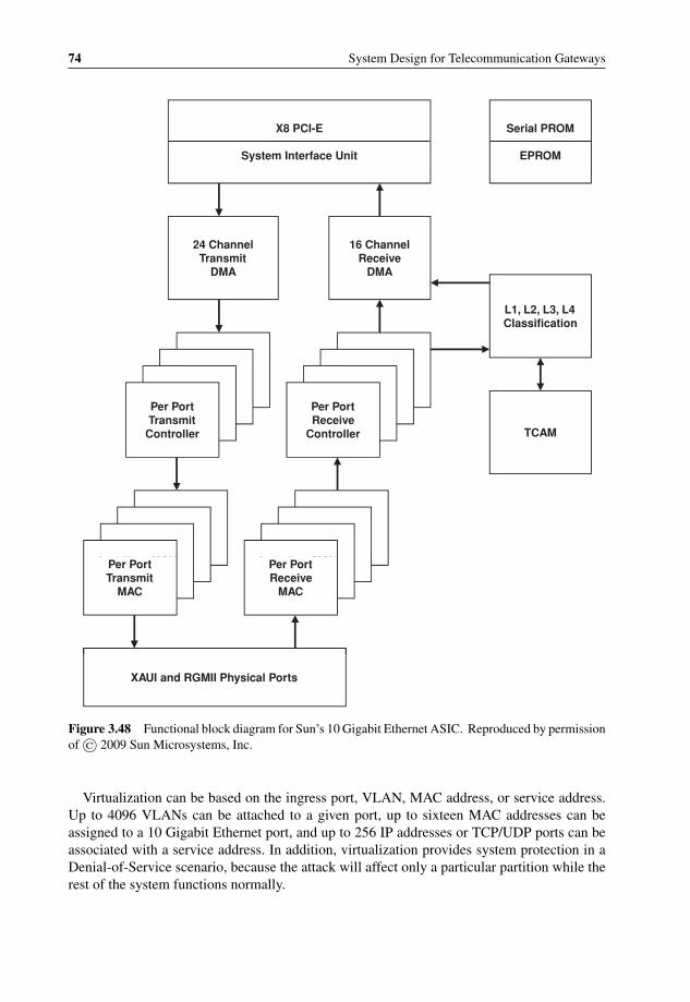
P1: OTA/XYZ P2: ABCc03 BLBK307-Bachmutsky September 2, 2010 13:12 Printer Name: Yet to Come
74 System Design for Telecommunication Gateways
Serial PROM
EPROM
X8 PCI-E
System Interface Unit
24 ChannelTransmit
16 ChannelReceive
Per PortPer Port
DMA DMA
L1, L2, L3, L4Classification
ReceiveController
Per PortReceive
ControllerPer PortReceive
ControllerPer PortReceive
Controller
TransmitController
Per PortTransmit
ControllerPer PortTransmit
ControllerPer PortTransmit
Controller TCAM
Per PortTransmit
MACPer PortTransmit
MACPer Port
Per PortReceive
MACPer PortReceive
MACPer Port
MAC TransmitMAC
Per PortTransmit
MAC
MACReceiveMAC
Per PortReceive
MAC
XAUI and RGMII Physical Ports
Figure 3.48 Functional block diagram for Sun’s 10 Gigabit Ethernet ASIC. Reproduced by permissionof © 2009 Sun Microsystems, Inc.
Virtualization can be based on the ingress port, VLAN, MAC address, or service address.Up to 4096 VLANs can be attached to a given port, up to sixteen MAC addresses can beassigned to a 10 Gigabit Ethernet port, and up to 256 IP addresses or TCP/UDP ports can beassociated with a service address. In addition, virtualization provides system protection in aDenial-of-Service scenario, because the attack will affect only a particular partition while therest of the system functions normally.

P1: OTA/XYZ P2: ABCc03 BLBK307-Bachmutsky September 2, 2010 13:12 Printer Name: Yet to Come
Hardware Technologies and Platforms 75
3.1.2.10.2 Radisys ATCA SolutionsRadisys offers ATCA solutions from a single blade to complete application-ready platforms.The latter includes a number of options:
� Promentum SYS-6010 in a fourteen-slot 12U or a six-slot 5U form factors with 10Gbps switching module and a choice of different NPU-based and CPU-based line andprocessing blades. It comes with optionally pre-integrated platform software, includingLinux OS from Wind River (acquired by Intel) or MontaVista (acquired by Cavium Net-works), SA Forum HPI 1.1 compliant shelf management software with system managementinterfaces (CLI, SNMP, HPI, and RMCP) and even a part of the data plane processing(currently, only ATM-IP networking software for the line card is available, but more can beintegrated).
� Promentum SYS-6016, which is similar to the Promentum SYS-6010, but in a sixteen-slot13U form factor.
� Promentum SYS-6006, which is similar to the Promentum SYS-6010, but in a 6-slot lowprofile 5U form factor.
� Promentum SYS-6002 in a two-slot 2U form factor that supports two 8U (280 mm deep)node boards and two 8U (80 mm deep) rear transition modules. It does not require theswitch module assuming usage of blades with built-in switch, like Promentum ATCA-7220dual Cavium Networks OCTEON packet processing module, ATCA-9100 Media ResourceModule, and Promentum ATCA-1200 Quad AMC carrier module. Additional cost benefitcomes from the fact that the optional shelf management capabilities are hosted by one of theblades. The platform can be considered for some applications as a competitor for microTCA.
� The latest ATCA 4.0 platform with 10GBASE-KR and 40GBASE-KR4 capable backplaneand 40G switching capability.
The abovementioned Promentum ATCA-1200 Quad AMC carrier blade supports up tofour Single-Mid-size AMCs or up to two Double-Mid-size AMCs or their combination withdifferent AMC configurations, like PrAMC, security (IPsec/SSL), storage, I/O, etc. It inte-grates on the base board 1.5 GHz MPC8548 PowerQUICCTM III local management processorwith a redundant pair of 64 MB flash memory and miniDIMM for up to 2 GB of DDR2SDRAM; twenty-six- or twenty-four-port managed Broadcom Layer 2 Switch (BCM56302or BCM56300 correspondingly) connecting up to 5 Gigabit Ethernet links per AMC, dualGigabit Ethernet to the local management processor, and dual Gigabit Ethernet links to theATCA Base interface; dual 10 Gigabit Ethernet links to the ATCA Fabric interface; networktiming switch for clock distribution to synchronous I/O interfaces (STM-1/OC 3, E1/T1) onAMCs; and PCI Express switch with 8x PCIe from the local management processor and 2xPCIe from each AMC.
The Promentum ATCA-4300 dual Intel 2 GHz dual-core Xeon blade also supports two AMCslots for the functionality extension or additional I/O capabilities. In addition, the PromentumATCA 4310 comes with dual 10 Gigabit Ethernet links to the fabric interface. The latest, asof the time of writing, ATCA 4500 doubles the previous generation performance; it includesthe L5518 Intel Xeon processor with four dual-threaded cores and eight DDR3 DIMMs forup to 64 GB of memory, the 10 Gigabit Ethernet fabric connectivity, the AMC slot for extraprocessing, interfaces or storage and support for an optional RTM.
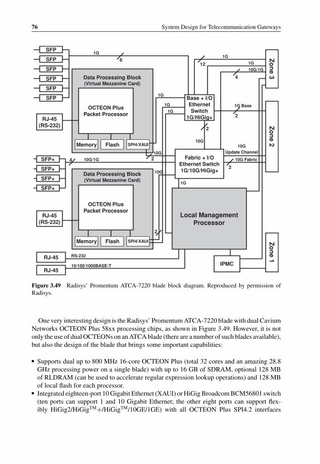
P1: OTA/XYZ P2: ABCc03 BLBK307-Bachmutsky September 2, 2010 13:12 Printer Name: Yet to Come
76 System Design for Telecommunication Gateways
SFP
SFP
SFP
SFP
SFP
SFP
SFP+
SFP+
SFP+
SFP+
RJ-45 (RS-232)
RJ-45 (RS-232)
RJ-45
RJ-45
Memory Flash SPI4/XAUI
OCTEON Plus Packet Processor
Data Processing Block (Virtual Mezzanine Card)
Memory Flash SPI4/XAUI
OCTEON Plus Packet Processor
Data Processing Block (Virtual Mezzanine Card)
Local Management Processor
IPMC
Zo
ne 1
Zo
ne 2
Zo
ne 3
Base + I/O Ethernet Switch
1G/HiGig+
Fabric + I/O Ethernet Switch 1G/10G/HiGig+
10/100/1000BASE-T
RS-232
10G/1G
10G/1G
1G
1G
1G
1G
1G
1G
1G
10G
10G
10G
10G Fabric
10GUpdate Channel
1G Base
612
4
4
2
2
2
2
2
Figure 3.49 Radisys’ Promentum ATCA-7220 blade block diagram. Reproduced by permission ofRadisys.
One very interesting design is the Radisys’ Promentum ATCA-7220 blade with dual CaviumNetworks OCTEON Plus 58xx processing chips, as shown in Figure 3.49. However, it is notonly the use of dual OCTEONs on an ATCA blade (there are a number of such blades available),but also the design of the blade that brings some important capabilities:
� Supports dual up to 800 MHz 16-core OCTEON Plus (total 32 cores and an amazing 28.8GHz processing power on a single blade) with up to 16 GB of SDRAM, optional 128 MBof RLDRAM (can be used to accelerate regular expression lookup operations) and 128 MBof local flash for each processor.
� Integrated eighteen-port 10 Gigabit Ethernet (XAUI) or HiGig Broadcom BCM56801 switch(ten ports can support 1 and 10 Gigabit Ethernet; the other eight ports can support flex-ibly HiGig2/HiGigTM+/HiGigTM/10GE/1GE) with all OCTEON Plus SPI4.2 interfaces

P1: OTA/XYZ P2: ABCc03 BLBK307-Bachmutsky September 2, 2010 13:12 Printer Name: Yet to Come
Hardware Technologies and Platforms 77
converted to 10 Gigabit Ethernet. The switch allows for connection between two OCTEONprocessors through dual ports to each one of them, accommodates four external 10 GigabitEthernet ports with SFP+ interfaces on the front panel, four 10 Gigabit Ethernetports to the Zone 3 connector for optional RTM expansion, two ports to backplanefabric interface and the connection to a secondary Gigabit Ethernet switch. In additionto connectivity, the switch has built-in Layer 2 and Layer 3 (IPv4 and IPv6) process-ing capability with 196 Gbps of line rate QoS-aware processing. It allows isolation ofa single OCTEON failure, performing load balancing of the traffic between OCTEONprocessors, enforcing Ethernet Link Aggregation (LAG), and many other tasks helpingsignificantly in the packet processing path in addition to the above mentioned 28.8 GHzof OCTEON processing capacity. The switch can be managed through CLI and SNMPv2and supports many standard and enterprise MIBs, including IETF RFC1213, RFC1907,RFC2863, RFC2011, RFC2012, RFC2013, RFC1493, RFC2674, RFC2665, RFC2819, andIEEE8023-LAG-MIB.
� Integrated 24-port Gigabit Ethernet Broadcom BCM56317 switch with two uplink 10 GigabitEthernet or HiGig ports to the 10 Gigabit Ethernet switch for traffic aggregation describedabove, six external SFP-based Gigabit Ethernet interfaces on the front panel, twelve GigabitEthernet ports routed to Zone 3 RTM for connectivity expansion, two ports to the backplanebase interface and additional port to the Local management processor complex. It has manyhigh-end capabilities of the main 10 Gigabit Ethernet switch.
� Local Management Processor (LMP) is implemented using 1.5 GHz Freescale MPC8548PowerQUICC III with 1 GB of DDR2 memory and 256 MB of local flash forconfiguration, Linux boot image and the file system. The LMP module includes a10/100BASE-T management interface to the front panel. It might appear to be strangehaving a separate LMP with so much processing power available from Cavium NetworksOCTEON processors, but the LMP is very strategic for Radisys high-end products,
because it allows standardizing on management APIs and management software inde-pendently on the data processing done using CPUs, NPUs, DSPs, ASICs or FPGAs. Itoffloads such processors to make sure that they are focused on their main task: the datahandling. LMP manages all on-board switches and other components, while performingmany other tasks including blade health management, module management, log manage-ment, IP services management, software and firmware (image) management, and flash/filesystem management.
� Network Timing Subsystem routes backplane synchronous clocking signals to LMP andOCTEON processors with hitless switchover support.
� The available RTM module provides additional 16 Gigabit Ethernet external SFP portsand dedicated 10/100BASE-T management interface to LMP for possible separated boxmanagement network connectivity. In the future, Radisys also plans to offer quad 10 GigabitEthernet RTM taking advantage of all of the high speed connectivity offered by the baseboard.
The board comes with integrated Wind River (acquired by Intel) PNE LE CG Linux forcontrol and management plane applications and Simple Executive OS based software fordata plane packet processing including IP forwarding, filtering and tunneling, traffic manage-ment (DiffServ), IPsec/TLS, Network Address Translation (NAT), load balancing and manyother features.

P1: OTA/XYZ P2: ABCc03 BLBK307-Bachmutsky September 2, 2010 13:12 Printer Name: Yet to Come
78 System Design for Telecommunication Gateways
3.1.2.10.3 Continuous Computing ATCA SolutionsContinuous Computing is well-positioned to provide ATCA-based solutions, because thecompany both develops its own ATCA blades and platform software to simplify and shortenproduct development.
Continuous Computing offers two-slot AC/DC 3U FlexChassisTM ATCA-SH20, six-slotAC/DC 5U FlexChassis ATCA-SH61 and fourteen-slot AC/DC 12U FlexChassis ATCA-SH140 chassis.
For processing based on x86 architectures, Continuous Computing has a FlexComputeTM
ATCA-XE60 blade with two quad-core Intel Xeon processors, up to 64 GB of memory,dual Gigabit Ethernet to the base fabric, dual front and rear Gigabit Ethernet for externalconnectivity and fabric mezzanine card for a flexible fabric interface integration (dual 1 and10 Gigabit Ethernet options are supported).
One outstanding ATCA board design is the FlexPacketTM ATCA-PP50 blade (see Figure3.50 for its block diagram) with dual 1 GHz NetLogic XLR732 multicore processors (seeSection 3.5.6.2.7) and 16 GB of memory. Each processor provides eight quad-threaded coresand contains a built-in security co-processor capable of handling up to 10 Gbps of bulkencryption/decryption (20 Gbps per blade). An integrated 10 Gigabit Ethernet switch connectsprocessors, two 10 Gigabit Ethernet external ports on the front panel, additional two 10 GigabitEthernet ports and ten 1 Gigabit Ethernet ports coming from an optional RTM and two 10Gigabit Ethernet ports to/from the fabric interface. An additional integrated Gigabit Ethernetswitch serves more external Gigabit Ethernet ports on the front panel and basic interface towardthe switch fabric. A per-processor CompactFlash card is also supported. The board supportstwo mezzanine cards: one for 36 Mbit or 72 Mbit NetLogic NL71024 TCAM to accelerate
Figure 3.50 Continuous Computing FlexPacket ATCA-PP50 with dual NetLogic XLR732 multicore.Reproduced by permission of CCPU.

P1: OTA/XYZ P2: ABCc03 BLBK307-Bachmutsky September 2, 2010 13:12 Printer Name: Yet to Come
Hardware Technologies and Platforms 79
table lookup operations; the second proprietary HyperTransport mezzanine for specializedoff-load engines, including custom user-specific ASIC and/or FPGA implementations.
The integrated software includes Wind River (acquired by Intel) Carrier-Grade Linux PNELE, NetLogic Thin Executive Operating System (Simple Executive type OS for data planeprocessing using regular ‘C’ programming language), network and routing protocols includingdata and control plane functions, like IPv4 and IPv6 forwarding, IPsec, tunneling, etc.
The FlexPacket ATCA-PP50 blade can be used as a load balancing blade between otherprocessing blades in ATCA system (see Figure 3.51), and the load balancing algorithm can bebased on Layer 2, Layer 3, or DPI load distribution rules.
The FlexTCATM platform (see Figure 3.52 for the architecture diagram) can bepre-integrated with the following software components: GoAhead SAFfire SA Forumcompliant high availability middleware (see Section 4.2.1.18), including AvailabilityManagement Framework, Checkpoint Service, Cluster Membership Service, Event Service,Information Model Management Service, Log Service, Messaging Service, and Notifica-tion Service; Trillium R© Essential Services with platform configuration services, switch andlink fault detection and failover, bonding Ethernet driver for IEEE 802.3ad Link Aggrega-tion (LAG), system diagnostics and remote console access, firmware upgrades, etc.; TrilliumProtocol Integration SDK, which supports an extensive set of different protocols for differ-ent application needs, such as fault-tolerant control plane protocols for LTE, Femtocell, 3G,
Figure 3.51 Internal traffic load balancing using Continuous Computing FlexPacket ATCA-PP50.Reproduced by permission of CCPU.
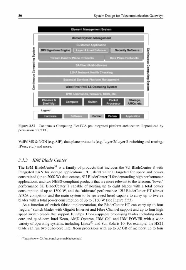
P1: OTA/XYZ P2: ABCc03 BLBK307-Bachmutsky September 2, 2010 13:12 Printer Name: Yet to Come
80 System Design for Telecommunication Gateways
Figure 3.52 Continuous Computing FlexTCA pre-integrated platform architecture. Reproduced bypermission of CCPU.
VoIP/IMS & NGN (e.g. SIP), data plane protocols (e.g. Layer 2/Layer 3 switching and routing,IPsec, etc.) and more.
3.1.3 IBM Blade Center
The IBM BladeCenter34 is a family of products that includes the 7U BladeCenter S withintegrated SAN for storage applications, 7U BladeCenter E targeted for space and powerconstrained (up to 2000 W) data centres, 9U BladeCenter H for demanding high performanceapplications, and two NEBS-compliant products that are more relevant to the telecom: ‘lower’performance 8U BladeCenter T capable of hosting up to eight blades with a total powerconsumption of up to 1300 W, and the ‘ultimate’ performance 12U BladeCenter HT (directATCA competitor and the main system to be reviewed here) capable to carry up to twelveblades with a total power consumption of up to 3160 W (see Figure 3.53).
As a function of switch fabric implementation, the BladeCenter HT can carry up to four‘regular’ switch blades with Gigabit Ethernet and Fibre Channel support and up to four highspeed switch blades that support 10 Gbps. Hot-swappable processing blades including dual-core and quad-core Intel Xeon, AMD Opteron, IBM Cell and IBM POWER with a widevariety of operating systems, including Linux R© and Sun Solaris 10. For example, the HS21blade can run two quad-core Intel Xeon processors with up to 32 GB of memory, up to four
34 http://www-03.ibm.com/systems/bladecenter/.

P1: OTA/XYZ P2: ABCc03 BLBK307-Bachmutsky September 2, 2010 13:12 Printer Name: Yet to Come
Hardware Technologies and Platforms 81
Figure 3.53 IBM Blade Center HT. Reprint Courtesy of International Business Machines Corporation,© 2006 International Business Machines Corporation.
hard disks and up to 8 Gigabit Ethernet ports with additional optional expansions for iSCSI,2 Gbps or 4 Gbps Fibre Channel, Myrinet, and x1 or x4 InfiniBand. Another interestinghigh performance dual-socket blade is the LS42 that integrates up to four quad-core AMDOpteron processors (with full cache coherency for a large SMP system) and up to 128 GB ofmemory. Multiple switch fabric modules (many of them through partners) support Ethernet,Fibre Channel, InfiniBand and SAS interfaces. The Cisco Systems’ Catalyst Switch Module3110 runs Cisco IOS and integrates four external Gigabit Ethernet ports or a single external10 Gigabit Ethernet port. The BNT (BLADE Network Technologies, created in 2006 fromthe Nortel’s Blade Server Switch Business Unit) 1/10 Gbps Uplink Ethernet Switch Modulehas six external Gigabit Ethernet ports and three external 10 Gigabit Ethernet ports. The BNT10 Gbps Ethernet Switch Module integrates ten external SFP+ based 10 Gigabit Ethernet portsand fourteen 10 Gigabit Ethernet ports to each blade in the system (there is a smaller switchmodule with six external 10 Gigabit Ethernet ports). BNT also provides the Layer 2-Layer 7Gigabit Ethernet Switch Module with four external Gigabit Ethernet ports. The available FibreChannel solutions include switch modules and expansion cards from Cisco Systems, Brocade,QLogic and Emulex. InfiniBand solutions include products from Cisco Systems, QLogic andVoltaire.
Another unique blade is PN41 which combines the capabilities of BladeCenter with theperformance of the CloudShield DPI engine (see Section 3.5.5.5). The blade contains an IntelIXP2805 network processor for use in handling packets, a regular expression accelerator tospeed up string searches, optical XFP 10 Gigabit Ethernet port for data traffic and a SFPGigabit Ethernet port for data capture and debugging.

P1: OTA/XYZ P2: ABCc03 BLBK307-Bachmutsky September 2, 2010 13:12 Printer Name: Yet to Come
82 System Design for Telecommunication Gateways
Of course, there are many more blades available. The IBM BladeCenter is an excellent familyof products, but even with all of the partners mentioned above, the BladeCenter ecosystem isstill far from that developed for ATCA. To extend the number of partners, IBM has openedthe BladeCenter specifications and software interfaces, but there is a much higher probabilitythat some emerging technologies (for example, Cavium Networks or NetLogic multicoreprocessors, EZChip or Xelerated network processors, and many others) will be available forthe ATCA system way ahead of their availability for the IBM BladeCenter. With this largeecosystem, the ATCA is still behind the IBM BladeCenter in shipped volumes and pricingbased on a comparison presented by Daniel Dierickx, CEO of e2mos, at the MicroTCAConference in the UK in September 2008.
The IBM BladeCenter offers an excellent software suite for control and management planes.Some ATCA vendors, such as Continuous Computing and Radisys, have also started to offerapplication-ready platforms with fully pre-integrated and pre-tested hardware and softwarebundles.
Cisco Systems may also enter the market with ATCA system(s). In addition, they arelobbying for the enhanced ATCA with up to fourteen double blades by making the ATCAtwice as deep and inserting cards both from the front and from the back of the system asan extended RTM. Based on supportive statements from Kevin Bross, a Modular SystemsArchitect at Intel, it appears that Intel likes that idea also. Cisco Systems proposes to focus onthe cooling problem and consider potentially liquid cooling. The company would like to see amigration of the ATCA from a pure telecom platform to the data center market (the oppositeof all previous platform migrations) by reducing the NEBS requirements to a narrower rangeof temperatures while easing DC power efficiency levels for energy saving.
IBM is also not sitting idle. At the end of October 2008, ‘IBM and Intel Corporation todayannounced they are extending their collaboration in the blade server market to drive adoption ofan open industry specification for blade switches. This will enable switch vendors to maximizereturn on their research and development by developing products to a single design, reachingmore customers with just one product. . . IBM will extend the BladeCenter switch specificationfor blade servers to the Server Systems Infrastructure (SSI) organization on a royalty-freebasis, allowing switch vendors to create one product that works across the BladeCenter andSSI ecosystems and driving more switch products for clients to choose from. The companiesannounced plans to work together to establish a third-party Switch Compliance Lab, wherethe developer community can test and verify their blade server products for BladeCenter andSSI environments’.35
It is easy to see that the competition between the IBM BladeCenter and ATCA is heating up,which is a very good news for the technology and equipment manufacturers. After the IBM-Intel announcement, Mark Leibowitz, a senior principal engineer at BAE Systems, said thathe predicts a ‘war’ between the IBM BladeCenter and ATCA, including government RFPs,referring to a huge deal with the US Navy which was planning to compare both solutionsduring 2009.
A few interesting comments came from Cisco Systems’ Chuck Byers.36 He called for moreflexible supply chain partnerships to help reduce ATCA system costs which can be as muchas double those of the IBM Blade Center systems per CPU. Byers believes that it could take
35 http://www-03.ibm.com/press/us/en/pressrelease/25747.wss.36 http://www.eetimes.com/showArticle.jhtml?articleID=211600306.
P1: OTA/XYZ P2: ABCc03 BLBK307-Bachmutsky September 2, 2010 13:12 Printer Name: Yet to Come
Hardware Technologies and Platforms 83
two years to get the ATCA community geared up to make the kinds of chassis and boards hewould like to see. On the other hand, he claims that IBM’s Blade Center systems have limitedscalability because of the collision between internal cables and airflow paths.
Reading these comments, it sounds like Mark Leibowitz is right. We can only hope that the‘war’ will produce even better platforms that all of us will enjoy.
3.1.4 Comparison of Form Factors
There is a perception that a bladed chassis represents a more cost efficient solution thanthe pizza box. The validity of this claim depends on the circumstances. If additional bladesare purchased on an ‘as you grow’ basis and the majority of systems at the end of theirlifetime will not be fully filled with blades, it was potentially not very cost efficient. Also, theentry-level system price with minimal number of blades can be significantly more expensivethan a corresponding pizza-box configuration, meaning that the initial competitiveness of amulti-bladed chassis is lower.
In some cases the cost efficiency calculation is in itself questionable. It is true that a singlelarge power supply is cheaper than many smaller ones, but power supplies are usually a minorpart of the entire system cost; and in addition multiple smaller power supplies can providehigher availability. It is true that larger fans are more efficient than smaller ones, but thesystems are more sensitive to a single large fan failure. It means that in the case of a large fanor power supply failure they have to be replaced urgently with corresponding OPEX increase.On the other side, many vendors claim much more efficient server farm deployments withbladed systems: ‘A SuperBlade server can save more than 100 watts over a traditional discrete1U rack-mount server. These savings add up quickly when your SuperBlade chassis is fullypopulated with 10 servers. By eliminating the overhead in 1U discrete servers and using thehigh efficiency (up to 93%) power supplies, SuperBlade can save you $700–$1,000 per yearin power for your servers and even more when you add the reduced cooling costs’.37
When comparing the empty chassis cost, a large bladed system chassis is frequently moreexpensive than all of the corresponding pizza boxes together; for example, a 10U chassis cancost more than 10x a 1U pizza-box chassis. Also, with blade and backplane connectors it isvery expensive to allow for large amount of blade inserts and removals; pizza box interconnectis through external cables that are simpler and cheaper and easier to replace. On the otherhand, a bladed system requires significantly fewer cables and additional cabling means moreplanning, more maintenance and more failures with increased OPEX.
The vast majority of the cost – up to 80% – is the processing subsystem, and that cost isusually lower for a pizza box driven by more efficient cooling (for example, there is morespace for a heat sink), capability to use higher performance parts with better price/performanceratio and lower power restrictions, use of cheaper memory components (regular desktop-likeDIMMs instead of laptop-like SO-DIMMs), and more space on the blade by reserving thespace for injectors’ connectors on blades. At the same time, shared power supplies in bladedsystems save a lot of space.
Interesting and surprising results were published in July 2008 by InformationWeek as apart of the RFP for an imaginary TacDoh networking project.38 While many respondents
37 http://www.supermicro.com/products/SuperBlade.38 http://www.informationweek.com/news/infrastructure/showArticle.jhtml?articleID=209600406.

P1: OTA/XYZ P2: ABCc03 BLBK307-Bachmutsky September 2, 2010 13:12 Printer Name: Yet to Come
84 System Design for Telecommunication Gateways
had proposed a chassis based solution, the 3COM offering was based entirely on stackableplatforms. The analysis states that stacking technology offers high capacity and resiliencysimilar to chassis switches and praises the 3COM stackable solution (see Section 3.2 for moreinformation) for its greater flexibility and lower cost while criticizing it for a lower interconnectthroughput as compared to a chassis backplane.
Not once does bladed servers’ marketing information refer to a significantly higher CPUdensity compared to pizza boxes (refer, for example, to Sun Blade 6048 with up to 768 coresper rack39), but unfortunately the comparison is not always apple-to-apple. Pizza box serverswere designed to be used as a standalone server and thus they include one or more diskbays, more interfaces, expansion slots and more. If pizza boxes are designed purposely forstackability, they can avoid all that overhead. For instance, a pizza box can host at least thesame amount of AMC blades (see later in this chapter) as any blade system. It proves that apizza box can be designed for a high processing density. One example of pizza box design isthe Advantech NCP-5120 that hosts at least thirty-two cores in 1U chassis with up to 1536cores in a rack (the thirty-two cores does not take into account additional PMC slot capabilitythat can host more processing cores making the total number even bigger). Of course, these aretotally different cores, they have different core frequencies, different processing capabilitiesand it is difficult to compare them in general terms. However, the main point to rememberhere is that the claims for density should not be taken at face value, they must be verified forspecific applications and business cases.
A slightly better comparison can be based on total processing power. One of the parametersis the pure core frequency of processing elements per 1U – it is 32 GHz (plus whatever canbe added on a PMC) for Advantech NCP-5120, 11.2 GHz for Sun Blade T6320. The problemis that hardware multithreading is not included in the computation and it definitely improvesperformance depending on the application, architecture principles, the number of hardwarethreads and processing requirements. Also, cores differ far beyond just clock values; they havedifferent instruction sets, some can process multiple instructions in every cycle, the numberof cycles per instruction varies, the instruction can do much more in some processors (forexample, usually network processor instructions can perform more actions simultaneously)and processors frequently have hardware offload engines that can improve performance signif-icantly for some applications. Greater detail about processors and their capabilities is providedin Section 3.5.
So which is better? As stated many times in this book, it depends on the application, therequirements of the specific product and the design optimization point. It is just as importantto understand all of the factors and parameters affecting the results of the comparison.
3.2 Stacking Chassis
Assuming that the problem of selecting the right chassis for a particular application is somehowsolved, frequently the next problem that arises is about chassis stackability; and here almosteverybody hits a roadblock. The reason for this is the lack of well-defined stackability principlesand standards to support such a functionality. For instance, the ATCA standard goes into agreat deal of detail to define a single chassis, but it has nothing beyond that and stacking of
39 http://www.sun.com/servers/blades/6048chassis/.
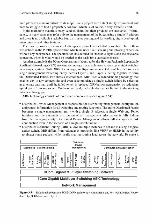
P1: OTA/XYZ P2: ABCc03 BLBK307-Bachmutsky September 2, 2010 13:12 Printer Name: Yet to Come
Hardware Technologies and Platforms 85
multiple boxes remains outside of its scope. Every project with a stackability requirement willneed to struggle to find a proprietary solution, which is, of course, a very wasteful effort.
In the marketing materials many vendors claim that their products are stackable. Unfortu-nately, in many cases they refer only to the management of the boxes using a single IP addressand there is no available stackable bus, distributed routing and forwarding, high-speed uplinkinterconnects and other features.
There were, however, a number of attempts to promote a stackability solution. One of themwas defined in the PC/104 specification which includes a self-stacking bus allowing expansionwithout any backplanes. The specification has defined all stackable signals and the stackableconnector, which is what would be needed as the basis for a stackable chassis.
Another example is the 3Com Corporation’s (acquired by the Hewlett Packard) ExpandableResilient Networking (XRN) stacking technology that enables one to stack up to eight switchesin a single system. With XRN technology, multiple interconnected switches behave as asingle management switching entity, across Layer 2 and Layer 3, acting together to formthe Distributed Fabric. For chassis interconnect, XRN uses a redundant ring topology thatenables any-to-any connectivity and even accommodates a single switch failure by selectingan alternate data path until the failed switch is replaced. XRN allows aggregation on redundantuplink ports from any switch. On the other hand, stackable devices are limited to the stackinginterface throughput.
XRN technology consists of three main components (see Figure 3.54):
� Distributed Device Management is responsible for distributing management, configurationand control information for all switching and routing functions. The entire Distributed Fabricbecomes a single management entity with a single IP address, a single Web and Telnetinterface and the automatic distribution of all management information is fully hiddenfrom the managing entity. Distributed Device Management allows full management taskcontinuation even in the scenario of a single switch failure.
� Distributed Resilient Routing (DRR) allows multiple switches to behave as a single logicalactive switch. DRR differs from redundancy protocols, like VRRP or HSRP, in the abilityto always route packets while locally sharing routing load across the network. To make it
Network Management
3Com Gigabit Multilayer Switching ASIC Technology
3Com Gigabit Multilayer Switching Software
AR
P T
able
s
Ro
ute
rIn
terf
aces
Ro
uti
ng
Tab
les
Ro
uti
ng
Pro
toco
ls
Acc
ess
Co
ntr
ol L
ists
SN
MP
Fab
ric
Co
nfi
gu
rati
on
ST
P &
RS
TP
802.
1QV
LA
Ns
Co
S &
Qo
S
Dev
ice
Sec
uri
ty
Gig
abit
Tech
no
log
y
LA
G G
rou
ps
LA
G P
ort
s
Dif
fere
nt
Med
ia
IEE
E80
2.3a
d
Distributed Link AggregationDistributed Resilient Routing
Distributed Device
Management
Figure 3.54 Relationship between 3COM XRN technology components and key technologies. Repro-duced by 3COM (acquired by HP).

P1: OTA/XYZ P2: ABCc03 BLBK307-Bachmutsky September 2, 2010 13:12 Printer Name: Yet to Come
86 System Design for Telecommunication Gateways
Synchronized Layer 3 Configuration and
Routing Information
XRN Distributed Fabric
R1 R2 R3 R1 R2 R3
R1
R2
R3
IP: 10.0.0.1/8MAC:0800.2c12.1234
IP: 20.0.0.1/8MAC:0800.2c12.1235
IP: 30.0.0.1/8MAC:0800.2c12.1236
Synchronized Layer 3 Configuration and
Routing Information
XRN Distributed Fabric
R1 R2 R3 R1 R2 R3
R1
R2
R3
IP: 10.0.0.1/8MAC:0800.2c12.1234
IP: 20.0.0.1/8MAC:0800.2c12.1235
IP: 30.0.0.1/8MAC:0800.2c12.1236
Figure 3.55 3COM XRN Distributed Resilient Routing component. Reproduced by 3COM (acquiredby HP).
happen, DRR distributes routing information across all switches in the Distributed Fabric(see Figure 3.55).
� Distributed Link Aggregation (see Figure 3.56) allows multiple switches to be connected tothe same next hop device, improving performance and reliability of the solution. The featurealso optimizes the traffic to minimize the load on XRN interconnect links.
The boundaries of XRN architecture are not clear, and nor is whether the eight distributeddevices represent the ultimate limit based on link capacities or protocol distribution, or whetherit is just a part of the marketing positioning not to compete with other high-end products.
3.3 Cluster Computing
Cluster computing has existed for a long time and is potentially the best method for systemscalability. Clusters are widely used in enterprise applications and hosted services, complexmathematical problems, modeling and massive data processing – very large applications
XRN Distributed FabricXRN Distributed Fabric
Figure 3.56 3COM XRN Distributed Resilient Routing component. Reproduced by 3COM (acquiredby HP).

P1: OTA/XYZ P2: ABCc03 BLBK307-Bachmutsky September 2, 2010 13:12 Printer Name: Yet to Come
Hardware Technologies and Platforms 87
that can be relatively easily parallelized. The most popular cluster implementations for thetelecommunication industry are a high-availability cluster used for active-standby redundancyand a load balancing grid, which is built using homogeneous or heterogeneous devices withthe traffic load balancing between these devices and a very low intra-cluster inter-devicecommunication.
Clusters can be viewed as a logical continuation of chip and blade scalability. For exam-ple, many state-of-the-art multicore processors (from Cavium Networks, NetLogic, Sun, andothers; see Section 3.5.6) are designed with an in-line hardware packet classification unitthat can parse packets, extract pre-configured or programmed protocol fields, calculate a hashfunction using these extracted fields and apply this hash function to schedule the packet toone of the processing cores or threads. A well-defined set of extracted fields can ensure thatthe packets belonging to the same stream or application are being processed by the samecore or thread, enhancing cache usage and minimizing the need for communication betweencores/threads, which in turn leads to a higher performance. When the communication or syn-chronization between cores or threads is inevitable, these multicore solutions offer either sharedmemory (external or internal scratchpad), or hardware-accelerated queues, semaphores andmailboxes.
The next level of load balancing clusters is a bladed system (multiple multicore processorscan be viewed logically as multiple blades), which not surprisingly has a similar architecture tothe multicore described above: a line card, implemented using a switch, CPU, NPU, FPGA orASIC, that can parse packets, extract pre-configured or programmed protocol fields, calculatea hash function using these fields and send the packet to a designated processing blade basedon this hash value. As with separate cores, every attempt is made to minimize a communicationbetween blades, because in the chassis such communication can easily become a bottleneckdriven by additional latencies through the switch fabric and the fact that in many designsthere is no shared memory between blades. An example of such a load balancing architectureis shown in Figure 3.51, illustrating one of the most popular architectures for data planeprocessing within a single chassis.
Load balancing between physical boxes in the grid is, again, similar to the descriptionof classifier and load balancer in the multicore chip or a line card in the bladed chassis. Adedicated box receives packets, extracts protocol fields from Layer 2, Layer 3, Layer 4 and/orLayer 7, calculates hash function and, based on the hash value, sends the packet to one ofthe processing boxes further down the network. The communication between boxes has tobe minimized as much as possible to be able to scale the system efficiently to the level ofhundreds and even thousands of devices per cluster. However, in most implementations somemessaging is required between boxes. Of course, it can be optimized by using a low-latencyinterconnect, such as InfiniBand, and/or kernel bypass techniques, such as RDMA, iWARPand others, but even with an optimized interconnect, the preferred solution is always to avoidcommunication between separate entities.
Another example of creating a grid of processing servers is the software called HAProxy,which can use the TCP splicing and Access Control List (ACL) or other algorithms (weightedround-robin, least sessions count, source address hash, URI, and URL parameters) to selectone of the processing servers for an HTTP session and redirect traffic to this server. HAProxyeven includes a keepalive mechanism to manage server health; this mechanism is based onperiodic HTTP requests. The addition of a mechanism similar to Amazon’s Elastic IP alsoenables high availability.
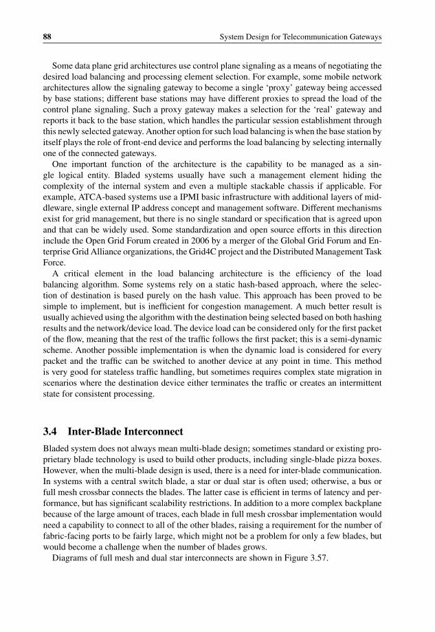
P1: OTA/XYZ P2: ABCc03 BLBK307-Bachmutsky September 2, 2010 13:12 Printer Name: Yet to Come
88 System Design for Telecommunication Gateways
Some data plane grid architectures use control plane signaling as a means of negotiating thedesired load balancing and processing element selection. For example, some mobile networkarchitectures allow the signaling gateway to become a single ‘proxy’ gateway being accessedby base stations; different base stations may have different proxies to spread the load of thecontrol plane signaling. Such a proxy gateway makes a selection for the ‘real’ gateway andreports it back to the base station, which handles the particular session establishment throughthis newly selected gateway. Another option for such load balancing is when the base station byitself plays the role of front-end device and performs the load balancing by selecting internallyone of the connected gateways.
One important function of the architecture is the capability to be managed as a sin-gle logical entity. Bladed systems usually have such a management element hiding thecomplexity of the internal system and even a multiple stackable chassis if applicable. Forexample, ATCA-based systems use a IPMI basic infrastructure with additional layers of mid-dleware, single external IP address concept and management software. Different mechanismsexist for grid management, but there is no single standard or specification that is agreed uponand that can be widely used. Some standardization and open source efforts in this directioninclude the Open Grid Forum created in 2006 by a merger of the Global Grid Forum and En-terprise Grid Alliance organizations, the Grid4C project and the Distributed Management TaskForce.
A critical element in the load balancing architecture is the efficiency of the loadbalancing algorithm. Some systems rely on a static hash-based approach, where the selec-tion of destination is based purely on the hash value. This approach has been proved to besimple to implement, but is inefficient for congestion management. A much better result isusually achieved using the algorithm with the destination being selected based on both hashingresults and the network/device load. The device load can be considered only for the first packetof the flow, meaning that the rest of the traffic follows the first packet; this is a semi-dynamicscheme. Another possible implementation is when the dynamic load is considered for everypacket and the traffic can be switched to another device at any point in time. This methodis very good for stateless traffic handling, but sometimes requires complex state migration inscenarios where the destination device either terminates the traffic or creates an intermittentstate for consistent processing.
3.4 Inter-Blade Interconnect
Bladed system does not always mean multi-blade design; sometimes standard or existing pro-prietary blade technology is used to build other products, including single-blade pizza boxes.However, when the multi-blade design is used, there is a need for inter-blade communication.In systems with a central switch blade, a star or dual star is often used; otherwise, a bus orfull mesh crossbar connects the blades. The latter case is efficient in terms of latency and per-formance, but has significant scalability restrictions. In addition to a more complex backplanebecause of the large amount of traces, each blade in full mesh crossbar implementation wouldneed a capability to connect to all of the other blades, raising a requirement for the number offabric-facing ports to be fairly large, which might not be a problem for only a few blades, butwould become a challenge when the number of blades grows.
Diagrams of full mesh and dual star interconnects are shown in Figure 3.57.
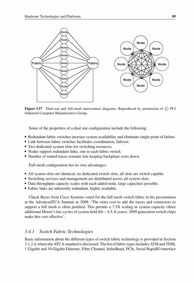
P1: OTA/XYZ P2: ABCc03 BLBK307-Bachmutsky September 2, 2010 13:12 Printer Name: Yet to Come
Hardware Technologies and Platforms 89
Node
Node
Node
Node
Node
Node
Node
Node
Node
Fabric Fabric
Node
Node Node
NodeNode
Node Node
Node
Node
Node
Node
Node
Node
Node
Node
Node
Fabric Fabric
Node
Node
Node
Node
Node
Node
Node
Node
Node
Fabric Fabric
Node
Node Node
NodeNode
Node Node
Node
Node
Node Node
NodeNode
Node Node
Node
Figure 3.57 Dual-star and full-mesh interconnect diagrams. Reproduced by permission of © PCIIndustrial Computer Manufacturers Group.
Some of the properties of a dual star configuration include the following:
� Redundant fabric switches increase system availability and eliminate single point of failure.� Link between fabric switches facilitates coordination, failover.� Two dedicated system slots for switching resources.� Nodes support redundant links, one to each fabric switch.� Number of routed traces remains low keeping backplane costs down.
Full mesh configuration has its own advantages:
� All system slots are identical, no dedicated switch slots, all slots are switch capable.� Switching services and management are distributed across all system slots.� Data throughput capacity scales with each added node, large capacities possible.� Fabric links are inherently redundant, highly available.
Chuck Byers from Cisco Systems voted for the full mesh switch fabric in his presentationat the AdvancedTCA Summit in 2008: ‘The extra cost to add the traces and connectors tosupport a full mesh is often justified. This permits a 7.5X scaling in system capacity (threeadditional Moore’s law cycles of system field life – 4.5–6 years). 2009 generation switch chipsmake this cost effective’.
3.4.1 Switch Fabric Technologies
Basic information about the different types of switch fabric technology is provided in Section3.1.2.4, where the ATCA standard is discussed. The list of fabric types includes ATM and TDM,1 Gigabit and 10 Gigabit Ethernet, Fibre Channel, InfiniBand, PCIe, Serial RapidIO interface

P1: OTA/XYZ P2: ABCc03 BLBK307-Bachmutsky September 2, 2010 13:12 Printer Name: Yet to Come
90 System Design for Telecommunication Gateways
1 2 N 1 2 N
Output PortsInput Ports
Shared Bus
1 2 N 1 2 N
Shared Bus
Figure 3.58 Shared bus architecture. Reproduced by permission of Dune Networks.
and others. Some switch fabrics, like AppliedMicro PRS and Dune Networks’ FE600, useproprietary and specially optimized protocols. However, even for the same technology thereare frequently many solutions available on the market, and this chapter provides the basicinformation that allows at least some level of comparison and understanding the applicabilityof these offerings for a particular application.
The first switching architecture was a shared bus (see, for example, a good article ‘Evolution:20 years of switching fabric’ by Dune Networks; the architecture diagram is shown in Figure3.58). The architecture does not permit any contention (only a single source can use the bus atany time) and an optional bus arbiter is designed in to solve such contentions as they arise. Theshared bus performance is limited by the bus speed itself and the performance of its centralizedarbiter.
Switch fabrics are designed to overcome the shared bus limitations. Their implementationcan be divided into groups based on the data buffering location:
� Bufferless switch fabric (used, for example, by Cisco Systems in its GSR routers andby Transwitch in its TXC-OMNI switch40) is based on the idea of requesting the datatransfer from the arbiter over the special control interface (multiple ports can request transfersimultaneously at any point of time), which in turn would decide what transfers can begranted, grant the access in the reply, followed by one or more data transfers (see Figure3.59). Buffering is done by the transferring entities on ingress (Virtual Output Queues, whichcan be considered an egress toward the switch fabric) and egress sides.
� Shared memory switch fabric, when the incoming data (from a switch point of view) iscopied into a shared memory space and then scheduled from that shared memory to thedestination egress port based on the required QoS.
One of the limitations of the shared memory approach is the total bandwidth required tobe supported by every integrated memory controller, which is 4xN, as shown in Figure 3.60.On the other hand, the architecture (implemented by vendors such as Juniper, Fulcrum andAppliedMicro) enables efficient QoS handling.
40 http://www.transwitch.com/products/product/page.jsp?product86.
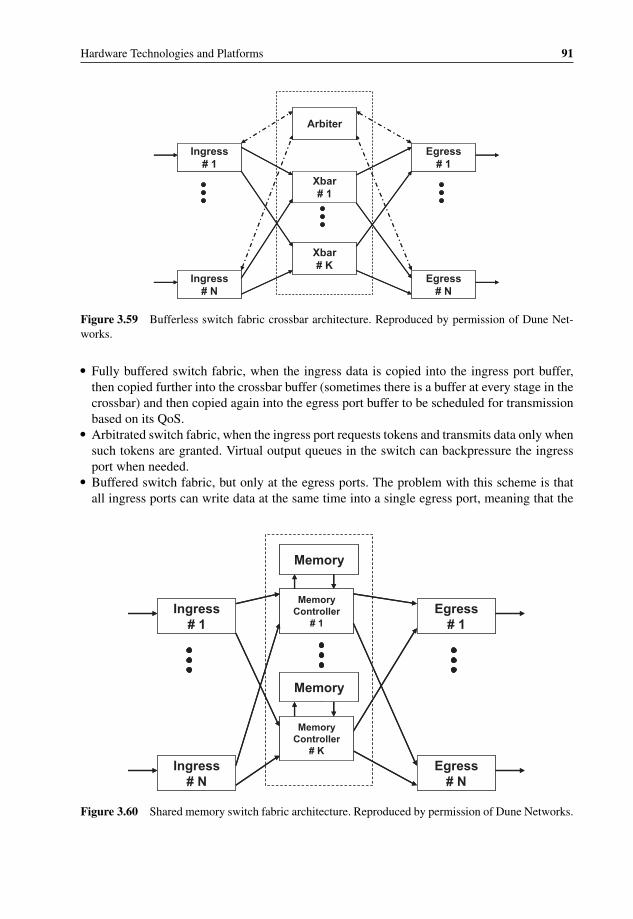
P1: OTA/XYZ P2: ABCc03 BLBK307-Bachmutsky September 2, 2010 13:12 Printer Name: Yet to Come
Hardware Technologies and Platforms 91
Ingress# 1
Ingress# N
Egress# 1
Egress# N
Arbiter
Xbar# 1
Xbar# K
Ingress# 1
Ingress# N
Egress# 1
Egress# N
Arbiter
Xbar# 1
Xbar# K
Figure 3.59 Bufferless switch fabric crossbar architecture. Reproduced by permission of Dune Net-works.
� Fully buffered switch fabric, when the ingress data is copied into the ingress port buffer,then copied further into the crossbar buffer (sometimes there is a buffer at every stage in thecrossbar) and then copied again into the egress port buffer to be scheduled for transmissionbased on its QoS.
� Arbitrated switch fabric, when the ingress port requests tokens and transmits data only whensuch tokens are granted. Virtual output queues in the switch can backpressure the ingressport when needed.
� Buffered switch fabric, but only at the egress ports. The problem with this scheme is thatall ingress ports can write data at the same time into a single egress port, meaning that the
Ingress# 1
Ingress# N
Egress# 1
Egress# N
Memory
MemoryController
# 1
Memory
MemoryController
# K
Ingress# 1
Ingress# N
Egress# 1
Egress# N
Memory
MemoryController
# 1
Memory
MemoryController
# K
Figure 3.60 Shared memory switch fabric architecture. Reproduced by permission of Dune Networks.

P1: OTA/XYZ P2: ABCc03 BLBK307-Bachmutsky September 2, 2010 13:12 Printer Name: Yet to Come
92 System Design for Telecommunication Gateways
switch fabric has to support Nx internal speedup to save all buffers from all N ingress portsin the same clock cycle. High speedup increases cost and complexity; therefore, a numberof schemes were developed with a smaller and lower cost speedup factor by allowing anon-zero very low probability of the data loss.
Depending on the number of ports, the internal switch architecture can be a single-stageor a multi-stage crossbar and can be arranged in a Clos, Banyan, Batcher-Banyan, Knockout,Benes, or other network type. The first two are described below.
The simplest symmetric Clos network can be described by a parameter (K, N, R), where Kis the number of middle switches, N is the number of ports on each input/output switch and Ris the number of input/output switches. An example of a Clos network with K middle switchesand N ports on each one of them is shown in Figure 3.61.
It is easy to recognize one of the great advantages of the Clos network – its relatively simplehierarchical scalability. Figure 3.61 shows the way to scale to 2Nx2N switch using only asmall number of N × N switches. Usually, a single ingress or egress port failure does not meanthat the traffic is lost, because in advanced implementation the system can find an alternateroute around the failure. For example, with the K middle switches in Figure 3.61, a single portfailure between middle switch #1 and an egress port #1 will reduce the traffic to port #1 onlyby 1/Kth without affecting any other ports. Figure 3.62 shows a 16 × 16 Clos switch withinternal interconnects.
While the Clos network can work, generally speaking, with statically configured intercon-nect paths, such a configuration would work efficiently in TDM-like networks, as opposed to
Egress# 1
NxN#1
Egress# N
Ingress# 1
Ingress# N
NxN#K
NxN
NxN
NxN
NxN
NxN
NxN
NxN
2Nx2N SwitchNxN Switch
Egress# 1
NxN#1
Egress# N
Ingress# 1
Ingress# N
NxN#K
NxN
NxN
NxN
NxN
NxN
NxN
NxN
Figure 3.61 Clos network architecture and its hierarchical scalability. Reproduced by permission ofDune Networks.

P1: OTA/XYZ P2: ABCc03 BLBK307-Bachmutsky September 2, 2010 13:12 Printer Name: Yet to Come
Hardware Technologies and Platforms 93
4x8
4x8
4x8
4x8
8x4
8x4
8x4
8x4
4x4
4x4
4x4
4x4
4x4
4x4
4x4
4x4
4x8
4x8
4x8
4x8
8x4
8x4
8x4
8x4
4x4
4x4
4x4
4x4
4x4
4x4
4x4
4x4
Figure 3.62 Example of 16 × 16 Clos network switch.
any-to-any packet networks. In more flexible dynamic configurations (used, for example, inCisco Systems’ CRS-1 and Juniper T/MX/EX series switches and routers) the entire trafficfrom any port of the switch is split between all middle switches and routed by all of theseswitches to their destination based on the embedded header information. Obviously, the bestresults occur when the traffic is split evenly between all middle switches and it works bestwhen the packets are split into smaller fixed-size portions, or cells, when only the last cell ofthe packet can become smaller. However, in such a design there is no simple way to ensurethat all cells will arrive at their destination in the order in which they were sent; therefore,packet reassembly is required at the egress port.
Another popular switch architecture uses a Banyan network approach (see Figure 3.63),which represents a family of single-path complex switches with a complexity in the order ofN∗log2 N as opposed to N2 for the crossbar.
Figure 3.63 Example of a single-path multistage Banyan switch.

P1: OTA/XYZ P2: ABCc03 BLBK307-Bachmutsky September 2, 2010 13:12 Printer Name: Yet to Come
94 System Design for Telecommunication Gateways
This lower complexity allows for efficient implementation of the switches with large numberof ports. On the other hand, Banyan networks are blocking inherently, causing significantperformance degradation with larger switches. Different techniques are applied to minimizethe blocking problem:
� Create multiple parallel networks (connected at the end to shared egress buffers) orextra stages in augment networks to provide multipath capability. Obviously, more parallelnetworks will provide better performance and additional resiliency, but will also increaseoverall complexity and cost. Each extra stage would double the number of available pathsdecreasing the probability for collision. For example, a Bense network adds (logN-1) stagesfor guaranteed non-blocking behavior. Another interesting implementation is when everymiddle switch is a self-routing switch, and when the path collision happens, the data is sentin the available but wrong direction and returned back in the next cycle.
� Implement multiple links between all middle switches and use them as a hop-by-hop multi-path. One problem with the implementation is that it introduces out-of-order, which is morecritical for ATM switching and requires re-ordering inside the switch fabric. However, this ispotentially less critical for packets, because packets are always fragmented and re-assembledand re-ordered at the end.
� Enforce a backpressure mechanism between the internal switches to delay the data insteadof dropping it.
� Add buffering at every middle switch to keep data in the collision scenario.� Combine Batcher and Banyan networks. In some implementations the collided data is
recirculated through the fabric again using internal loopbacks to idle ingress ports; if there isno available idle port, the data is buffered to wait for an available idle port to enable a losslessdelivery. The problem is that it is more difficult to implement a large Batcher-Banyan switch,because the Batcher network is inherently synchronous and is more complex than a Banyannetwork with the growth on the order of N∗log2N2.
� Add output queuing buffers.
Some of the implementations and enhancements described above can be beneficial for aparticular application, worst case scenario evaluation and typical traffic profiles. The mainmessage from the analysis above is that not all switches are created equal and that a switchdatasheet with claimed performance numbers might not be the only or the best way to comparedifferent alternatives.
3.4.2 Bandwidth Estimation and QoS in the Switch Fabric
In addition to non-blocking functionality, other critical functions of the switch fabric intelecommunication products are the correct required aggregate bandwidth and QoS-awareprocessing, including packet buffering and their desired scheduling as a part of the trafficmanagement solution (see [Axel K. Kloth] for the the implications of the introduction oftraffic management into the routing architecture). There are multiple factors, which must betaken into account:
� For pure throughput management purposes, the switch fabric can be overdesigned eitherinternally (meaning, it can handle much more traffic than claimed, which is a very expensive

P1: OTA/XYZ P2: ABCc03 BLBK307-Bachmutsky September 2, 2010 13:12 Printer Name: Yet to Come
Hardware Technologies and Platforms 95
approach), or by design, when a switch fabric with higher than needed capacity is usedfor the product, which is expensive, but is frequently used to protect system designs. Also,throughput overdesign does not guarantee that packets will not be lost. For instance, whenall ingress ports are switched to a single egress port, many switch fabrics will start losingpackets long before all ingress ports are saturated with the traffic. It is important to ensurethat device vendors calculate the throughput correctly, and in most cases the throughputhas to be equal to the number of ports multiplied by the port bandwidth. System architects,on the other hand, have to estimate not only the average and peak overhead of the packetswitching, such as SAR quantization efficiency described later, but to understand the dataflow in the system.
As an example, let us take a system containing one line card and one processing card,where every packet received by the line card will be forwarded to the processing cardthrough the switch fabric and will be sent back to the line card after processing and/ormodification to be sent out. In this scenario, every packet will flow through the switchfabric twice, so the correct throughput of such switch fabric has to double the aggregateexternal interface bandwidth. In a real-life situation the optimal calculation might be morecomplex. On the one hand, there can be a processor (CPU/NPU/FPGA/ASIC/switch) onthe line card that processes packets and can decide to forward a portion of the trafficdirectly to the egress port on the same line card without going through the switch fabric.Depending on the ratio of such traffic, it can reduce the fabric throughput requirementssignificantly. It is best practice to design and configure the system in a way that increasesthe percentage of locally routed packets. On the opposite side of the design approach, somesystems can be built as a functional pipeline by means of the packet processing; and a singlepacket would need to be handled by multiple processing blades depending on the blade’sfunctionality. Design-wise, it is a very simple and effective approach with easier scalingof every separate function up and down as required. This can be achieved by allocatingfor a particular function from a fraction of a single blade’s processing capacity to multipleprocessing blades working in a load balancing model. The disadvantage of such a design,in addition to the higher latency, is that a single packet can travel many times through theswitch fabric increasing its required total throughput; however, this would not be a problemfor the full mesh configuration. In some cases the approach still makes sense and should beconsidered.
� The throughput management of switch fabric has to take into account the high availabilityrequirements. It would be especially critical for active-active redundant switch fabric, whereone of devices has to take over the traffic previously processed by the failed device. Onepopular solution is to use a 2 + 1 redundancy model with three switches, each one handlingup to 50% of the traffic allowing for a single switch failure without affecting the overallsystem throughput. Also, some configurations, such as a full mesh, could assume the built-inresiliency, which is correct if one disregards the additional latency for multi-hop switchingand load on particular link(s). These failure aspects have to be considered for architectureand implementation decision making. Additional parameters that must be checked are thelogical connection setup/teardown times and redundancy switchover time which affect bothswitch failure handling and run-time blade insertion and removal.
� When the overload in the switch occurs (for example, buffers are filled up to the pre-configured threshold), there is a need to control the incoming traffic. This flow control, orbackpressure, mechanism has to be very intelligent in order to ensure that the least damage

P1: OTA/XYZ P2: ABCc03 BLBK307-Bachmutsky September 2, 2010 13:12 Printer Name: Yet to Come
96 System Design for Telecommunication Gateways
is done based on that control. The flow control can be global, per-port, per-virtual port, oreven per-flow. The higher granularity will give better results.
� If there is any packet drop occurring in the switch, the design has to ensure that the lowestpriority data is being dropped.
� Correct processing of latency-sensitive data is required. For example, there can be a situationwhen one ingress port receives a small latency-critical packet, such as voice, and all otherports have received large low-priority and latency-insensitive packets. If that small packethas to wait for all the rest to be transmitted ahead of it, the latency could become intolerableeven if no data is lost.
� Similar to latency, jitter can be a critical parameter for many applications. Without QoSawareness, it is very difficult, if not impossible, to control and enforce any jitter requirements.
� Data priority can be based either on information received within the data itself, such aspacket headers inserted by the data originator or a previous processing element, or based onsome configuration policies. For example, some switch ports could be more important thanothers so as to ensure the proper handling of control plane communication.
� There could be a need to handle different types of data simultaneously, such as IP, ATM,TDM and others. Multi-service implementation is one of the most complex problems tosolve. Sometimes switch implementation splits all data into smaller cell-like fixed-size datachunks so as to even out the conflicting aspects of different protocols. It requires an integratedsegmentation-reassembly (SAR) functionality with additional buffering, but some vendorsclaim that it is a small price to pay for improved performance, a degree of QoS control andoverall switch architecture. In some cases at least part of the SAR functionality is externalto the switch by means of using the cell-based interfaces. There are a number of standardsgoverning these types of interfaces: Common Switch Interface-Layer 1 (CSIX-L1), theSystem Packet Interface (SPI), the Network Processing Forum Streaming Interface (NPSI)and the emerging standard that uses the PCI Express infrastructure. For instance, the cells,Cframes, exchanged across the CSIX-L1 interface consist of an 8-byte base header and anoptional extension header, the payload (64/96/128/256 bytes depending on the switch fabricimplementation and configuration) and a vertical parity word. As seen from the CSIX framestructure, any external portion of SAR functionality involves sending additional headersreducing the effective data throughput being sent over the interface, which can become asignificant overhead for small-size cells. Another disadvantage of having the external fixed-size cell SAR is that it causes the last cell of the frame to be incomplete, wasting additionalbandwidth. The worst case scenario is when all of the frames are arriving in a size whichcauses the generation of two cells with only a single byte of payload in the second one.In this scenario, less than half of the interface throughput is used for actual data transfer.For all practical purposes, the probability of this happening is extremely small and thatprobability might not warrant switch fabric overdesign to support the worst case. Of course,another design option is to build the product with multiple switch fabrics in place, each oneoptimized for a specific traffic type, but the resulting complexity, cost, space, power andother parameters might become too prohibitive to proceed with that approach.
Some switch fabric interface chips rely at least partially on other components, such as NPUs,so as to better manage the QoS. Others (like some of Dune Networks/Broadcom/Fulcrum latestofferings) claim to have the capability to handle everything internally with not just basic QoS,but full per-flow traffic management capabilities and multi-layer QoS.

P1: OTA/XYZ P2: ABCc03 BLBK307-Bachmutsky September 2, 2010 13:12 Printer Name: Yet to Come
Hardware Technologies and Platforms 97
4 x OC-12 NP / TM(nP37xx)
NP / TM
NP / TM(nP37xx)
NP / TM(nP37xx)
NP / TM(nP37xx)
NP / TM
GE
GE
4 x GE
4 x OC-12
OC-48
FibreChannel
PRS C48X
PRS C192X
PRS C192X
CSIX / PL3
CSIX / PL3
CSIX
Protection Switch
Active Switch
PRS Q-80G(two, four, or eight per plane)
Backplane2x3.2 Gbps
2x3.2 Gbps
8x3.2 Gbps
8x3.2 Gbps
8x3.2 Gbps
8x3.2 Gbps
5 Gbps
20 Gbps
20 Gbps
Serial Links at
8b/10b coding)
4 x OC-12 NP / TM(nP37xx)
10G / OC-192NP / TM
NP / TM(nP37xx)
NP / TM(nP37xx)
NP / TM(nP37xx)
NP / TM
GE
GE
4 x GE
4 x OC-12
OC-48
FibreChannel
PRS C48X
PRS C192X
PRS C192X
Line Card
Line Card
Line Card
Protection Switch
Active Switch
PRS Q-80G
(two, four, or eight per plane)
5 Gbps
3.2 Gbps (with
Figure 3.64 AppliedMicro PRS Q-80G Switch with PRS C48X and PRS C192X Fabric Interfaces.Reproduced by permission of AppliedMicro.
3.4.3 Commercial Switch Fabric
There are multiple vendors offering switch fabric solutions; four of which are AppliedMicro,Broadcom, Fulcrum and Dune Networks (acquired by Broadcom in late 2009, but in this bookDune Networks’ products are kept separate from Broadcom’s offerings). It is important toremember that in full mesh configuration there is no need for separate switch fabric devicesand blades; the support either comes as a part of NPUs/switches or by using switch interfaceor traffic management devices on every blade connected directly to each other.
The AppliedMicro’s PRS family supports switching of all commonly used protocols such asTDM, ATM, Ethernet and IP. PRS Q-80G41 is the shared memory single-stage non-blockingcell switching device designed for systems up to 320 Gbps, with eight devices, of full-duplexaggregate user bandwidth with configurable cell size of 64, 72 or 80 bytes and 2x overspeedfactor per-port for wire-speed handling of all possible unicast, multicast and broadcast trafficpatterns. Multicast traffic is supported natively with cell replication at sending and the capa-bility for cells to be scheduled at different times for different output ports. In addition to theaggregation of multiple Gigabit Ethernet, 10 Gigabit Ethernet, OC-12, OC-48 and OC-192ports (see Figure 3.64), the PRS Q-80G also supports a 40 Gbps clear channel attachmentcapability, requiring a custom ASIC or FPGA to interface with a 40-Gbps protocol engine. Itsupports wire-speed QoS enforcement with up to four traffic priorities and multiple schedulingalgorithms (strict priority, weighted round-robin, exhaustive highest priority first), a determin-istic few microseconds latency for high priority traffic under worst case 100% traffic loadconditions and an end-to-end in-band flow control mechanism through the switch fabric. The
41 https://www.amcc.com/MyAppliedMicro/jsp/public/productDetail/product_detail.jsp?productID=PRSQ-80G.

P1: OTA/XYZ P2: ABCc03 BLBK307-Bachmutsky September 2, 2010 13:12 Printer Name: Yet to Come
98 System Design for Telecommunication Gateways
Scalable Tables(external memory)
PolicerManager
PacketParser
CounterManager
PacketEditorRange Finder
Classification Engine
Memory Manager
BroadSideLine-Rate Processor
Packet Buffer PCI
SPI-4.2SPI-4.224x10/100/1000
MACsXAUI
HiGig™XAUI
HiGig™
Scalable Tables(external memory)
PolicerManager
PacketParser
CounterManager
PacketEditorRange Finder
Classification Engine
Memory Manager
BroadSideLine-Rate Processor
Packet Buffer PCI
SPI-4.2SPI-4.224x10/100/1000
MACsXAUI
HiGig™XAUI
HiGig™
Figure 3.65 Broadcom BCM88020 24-port Gigabit Ethernet switch with uplink fabric. Reproducedby Broadcom.
PRS Q-80G can function in redundant configurations with automatic traffic redirection usinghot standby, load sharing or maintenance switchover (cell lossless) modes.
AppliedMicro also offers switch fabric chip-set nPX5500 integrated with NPU42 and sup-porting up to 20 Gbps full-duplex traffic, with up to 48 MB payload data buffering allocateddynamically across all ports, up to 512 K input and 512 K output flows, per-flow queuing andscheduling, virtual segmentation and reassembly (SAR) for packet switching and many otherfeatures.
Broadcom has a number of switch products that can be used for switch fabric connectivity.One of them is the 24-port Gigabit Ethernet switch BCM88020 (see Figure 3.65) with dual 10Gigabit Ethernet uplinks, HiGig+TM support and dual channelized SPI4.2 ports. The switch isbuilt using the shared memory approach and supports wire-speed handling of jumbo frames,any-to-any connectivity, lossless backpressure or priority tail drop and processor bypass formultiple traffic types, including Q-in-Q, MAC-in-MAC, MPLS and VPLS forwarding, IPv4and IPv6 unicast and multicast forwarding and tunneling. For higher scalability the switchsupports off-chip tables, meters and counters (high-resolution 64-bit counters are supported),
42 https://www.amcc.com/MyAppliedMicro/jsp/public/productDetail/product_detail.jsp?productID=nPX5500.
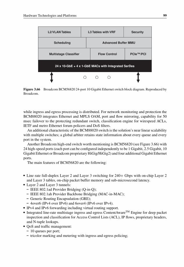
P1: OTA/XYZ P2: ABCc03 BLBK307-Bachmutsky September 2, 2010 13:12 Printer Name: Yet to Come
Hardware Technologies and Platforms 99
L2/VLAN Tables L3 Tables with VRF Security
Scheduling Advanced Buffer MMU
Multistage Classifier Flow Control PCIe™/PCI
24 x 10-GbE + 4 x 1-GbE MACs with Integrated SerDes
L2/VLAN Tables L3 Tables with VRF Security
Scheduling Advanced Buffer MMU
Multistage Classifier Flow Control PCIe™/PCI
24 x 10-GbE + 4 x 1-GbE MACs with Integrated SerDes
Figure 3.66 Broadcom BCM56820 24-port 10 Gigabit Ethernet switch block diagram. Reproduced byBroadcom.
while ingress and egress processing is distributed. For network monitoring and protection theBCM88020 integrates Ethernet and MPLS OAM, port and flow mirroring, capability for 50msec failover to the protecting redundant switch, classification engine for wirespeed ACLs,IETF and metro Ethernet forum policers and DoS filters.
An additional characteristic of the BCM88020 switch is the solution’s near linear scalabilitywith multiple switches; a global arbiter retains state information about every queue and everyport in the system.
Another Broadcom high-end switch worth mentioning is BCM56820 (see Figure 3.66) with24 high-speed ports (each port can be configured independently to be 1 Gigabit, 2.5 Gigabit, 10Gigabit Ethernet or Broadcom proprietary HiGig/HiGig2) and four additional Gigabit Ethernetports.
The main features of BCM56820 are the following:
� Line rate full-duplex Layer 2 and Layer 3 switching for 240+ Gbps with on-chip Layer 2and Layer 3 tables, on-chip packet buffer memory and sub-microsecond latency.
� Layer 2 and Layer 3 tunnels:– IEEE 802.1ad Provider Bridging (Q-in-Q);– IEEE 802.1ah Provider Backbone Bridging (MAC-in-MAC);– Generic Routing Encapsulation (GRE);– 4over6 (IPv4 over IPv6) and 6over4 (IPv6 over IPv4).
� IPv4 and IPv6 forwarding including virtual routing support.� Integrated line-rate multistage ingress and egress ContentAwareTM Engine for deep packet
inspection and classification for Access Control Lists (ACL), IP flows, proprietary headers,and N-tuple lookups.
� QoS and traffic management:– 10 queues per port;– tricolor marking and metering with ingress and egress policing;
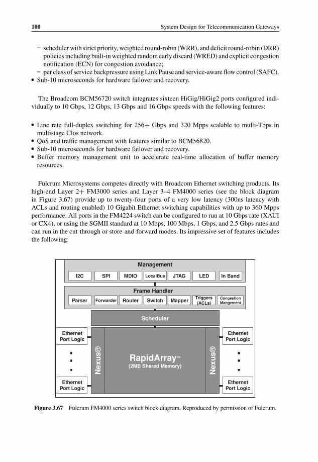
P1: OTA/XYZ P2: ABCc03 BLBK307-Bachmutsky September 2, 2010 13:12 Printer Name: Yet to Come
100 System Design for Telecommunication Gateways
– scheduler with strict priority, weighted round-robin (WRR), and deficit round-robin (DRR)policies including built-in weighted random early discard (WRED) and explicit congestionnotification (ECN) for congestion avoidance;
– per class of service backpressure using Link Pause and service-aware flow control (SAFC).� Sub-10 microseconds for hardware failover and recovery.
The Broadcom BCM56720 switch integrates sixteen HiGig/HiGig2 ports configured indi-vidually to 10 Gbps, 12 Gbps, 13 Gbps and 16 Gbps speeds with the following features:
� Line rate full-duplex switching for 256+ Gbps and 320 Mpps scalable to multi-Tbps inmultistage Clos network.
� QoS and traffic management with features similar to BCM56820.� Sub-10 microseconds for hardware failover and recovery.� Buffer memory management unit to accelerate real-time allocation of buffer memory
resources.
Fulcrum Microsystems competes directly with Broadcom Ethernet switching products. Itshigh-end Layer 2+ FM3000 series and Layer 3–4 FM4000 series (see the block diagramin Figure 3.67) provide up to twenty-four ports of a very low latency (300ns latency withACLs and routing enabled) 10 Gigabit Ethernet switching capabilities with up to 360 Mppsperformance. All ports in the FM4224 switch can be configured to run at 10 Gbps rate (XAUIor CX4), or using the SGMII standard at 10 Mbps, 100 Mbps, 1 Gbps, and 2.5 Gbps rates andcan run in the cut-through or store-and-forward modes. Its impressive set of features includesthe following:
I2C SPI MDIO LocalBus JTAG LED In Band
Parser Forwarder Router Switch Mapper Triggers (ACLs)
Congestion Mangement
Management
Frame Handler
Nex
us®
Nex
us®RapidArray™
(2MB Shared Memory)
Ethernet Port Logic
Ethernet Port Logic
Ethernet Port Logic
Ethernet Port Logic
Scheduler
I2C SPI MDIO LocalBus JTAG LED In Band
Parser Forwarder Router Switch Mapper Triggers (ACLs)
Congestion Mangement
Management
Frame Handler
Nex
us®
Nex
us®RapidArray™
(2MB Shared Memory)
Ethernet Port Logic
Ethernet Port Logic
Ethernet Port Logic
Ethernet Port Logic
Scheduler
Figure 3.67 Fulcrum FM4000 series switch block diagram. Reproduced by permission of Fulcrum.

P1: OTA/XYZ P2: ABCc03 BLBK307-Bachmutsky September 2, 2010 13:12 Printer Name: Yet to Come
Hardware Technologies and Platforms 101
� Layer 2 switching with 16K-entry MAC table, jumbo packet support of up to 16 KB, fullyprovisioned multicast, multiple spanning tree (IEEE 802.1D/s/w), independent and sharedVLAN learning, IEEE 802.1Q VLAN support.
� Layer 3 switching and routing with IPv4 and IPv6 lookups (up to16 K IPv4 entries or up to4 K IPv6 entries, 16 K-entry ARP table, fully-provisioned multicast routing, and full VLANreplication with multicast routing) and up to 4 K Layer 2, Layer 3 or Layer 4 ingress andegress ACL rules.
� Traffic management capabilities with line-rate Layer 2/Layer 3/Layer 4 traffic classification,metering and policing supporting IEEE 802.1p, IPv4 and IPv6 DSCP; IEEE 802.3x class-based (multi-colour) PAUSE flow control and IEEE 802.3ar rate control; flexible multi-levelscheduling using 200 ordering queues; and traffic separation through partitionable sharedmemory.
� Integrated multi-chip support enabling single point of management, remote learning,fat trees/meshes/rings, multi-chip mirroring, multi-chip link aggregation with sixteenports/group and total of 256 groups/system.
� Security support for IEEE 802.1X port-based security, MAC address security and DoSattacks prevention.
Fulcrum’s frame handler includes a number of processing blocks working with extremelylow latency thanks to shared memory architecture and efficient memory management. Evenfor the ‘simpler’ FM3000 series these blocks perform very extensive tasks (see Figure 3.68for the block diagram of some of them):
� The parsing block receives Ethernet or Inter-Switch Link (ISL) tagged frames, parses them,extracts the required fields and assigns processing priority based on either the policy (en-forced later by ACL processing rules), or information extracted from the packet, such asIEEE 802.1p (FM4000 takes into account Layer 3 QoS) and ISL tag.
� Filtering and forwarding block produces a set of ingress and/or egress ACL actions, such aspermit/deny/modify/count/mirror/trap/log, based on the pre-configured rules. The policingfunction is implemented using dual token buckets (tokens are used from the ‘committed’bucket first; when the ‘committed’ token bucket is depleted, packets are marked as yellowand will use the ‘excess’ token bucket), and rate-limiting function, which is based on sixteendrop-based rate limiters and the capability to generate PAUSE frames at the ingress. Theforwarding function uses a VLAN table, a spanning-tree state table and a MAC addresstable (FM4000 has IP and UDP/TCP port tables) to determine forwarding information withauto-learning capabilities. Up to 128-bytes of a frame header can be examined and up toseventy-eight of these bytes can be used for policy decisions. Integrated 512-entry × 36-bitby 32 slice TCAM block is used for key comparison and 512-entry x 40-bit by 32 sliceSRAM block is used to store the resulting ingress action(s), thus giving a total of 16K ACLrules for a flow-based classification. The filtering and forwarding block can be used forVLAN tag insertion, removal and/or modification, including replacement of one tag withanother, or encapsulation of the existing tag with an additional one.
� The port mapping block uses the forwarding information to retrieve a final destination portbit mask from the global routing table.
� The link aggregation (LAG) block hashes various header fields and determines which portof a link aggregation group will be used to transmit the frame, including the capability to
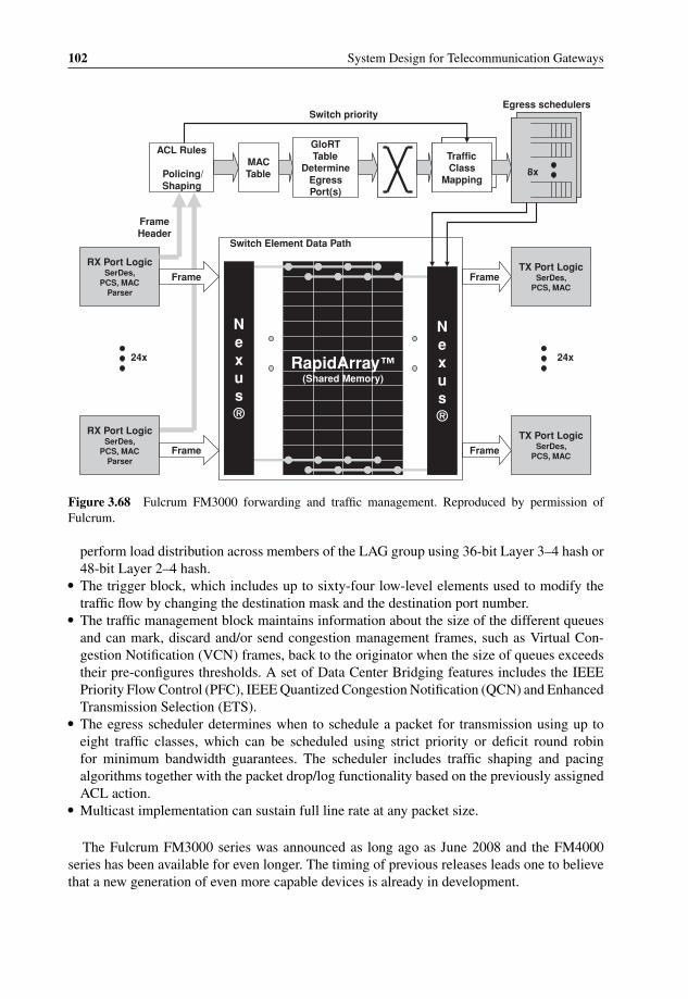
P1: OTA/XYZ P2: ABCc03 BLBK307-Bachmutsky September 2, 2010 13:12 Printer Name: Yet to Come
102 System Design for Telecommunication Gateways
8x8x
Egress schedulers
Traffic Class
Mapping
Traffic Class
Mapping
GloRTTable
Determine Egress Port(s)
MAC Table
ACL Rules
Policing/ Shaping
Switch priority
RX Port LogicSerDes,
PCS, MACParser
TX Port LogicSerDes,
PCS, MAC
TX Port LogicSerDes,
PCS, MAC
24x 24x
RX Port LogicSerDes,
PCS, MACParser
Frame
Frame
Frame Header
Frame
Frame
Switch Element Data Path
RapidArray™(Shared Memory)
Nexus®
Nexus®
Figure 3.68 Fulcrum FM3000 forwarding and traffic management. Reproduced by permission ofFulcrum.
perform load distribution across members of the LAG group using 36-bit Layer 3–4 hash or48-bit Layer 2–4 hash.
� The trigger block, which includes up to sixty-four low-level elements used to modify thetraffic flow by changing the destination mask and the destination port number.
� The traffic management block maintains information about the size of the different queuesand can mark, discard and/or send congestion management frames, such as Virtual Con-gestion Notification (VCN) frames, back to the originator when the size of queues exceedstheir pre-configures thresholds. A set of Data Center Bridging features includes the IEEEPriority Flow Control (PFC), IEEE Quantized Congestion Notification (QCN) and EnhancedTransmission Selection (ETS).
� The egress scheduler determines when to schedule a packet for transmission using up toeight traffic classes, which can be scheduled using strict priority or deficit round robinfor minimum bandwidth guarantees. The scheduler includes traffic shaping and pacingalgorithms together with the packet drop/log functionality based on the previously assignedACL action.
� Multicast implementation can sustain full line rate at any packet size.
The Fulcrum FM3000 series was announced as long ago as June 2008 and the FM4000series has been available for even longer. The timing of previous releases leads one to believethat a new generation of even more capable devices is already in development.
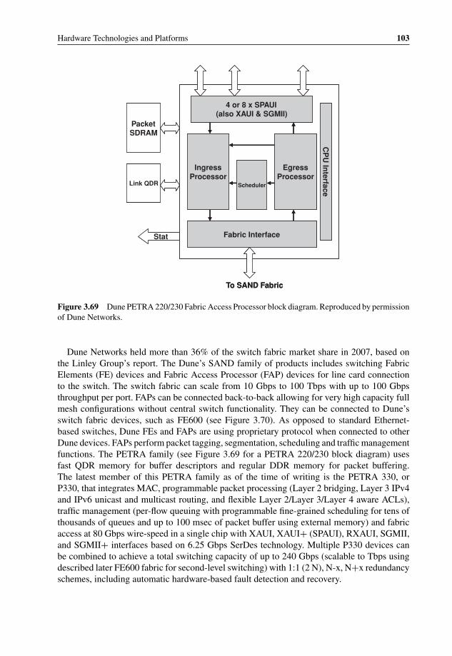
P1: OTA/XYZ P2: ABCc03 BLBK307-Bachmutsky September 2, 2010 13:12 Printer Name: Yet to Come
Hardware Technologies and Platforms 103
4 or 8 x SPAUI(also XAUI & SGMII)
Fabric Interface
IngressProcessor
EgressProcessor
Scheduler
CP
U In
terfacePacketSDRAM
Link QDR
Stat
To SAND Fabric
4 or 8 x SPAUI(also XAUI & SGMII)
Fabric Interface
IngressProcessor
EgressProcessor
Scheduler
CP
U In
terfacePacketSDRAM
Link QDR
Stat
To SAND Fabric
Figure 3.69 Dune PETRA 220/230 Fabric Access Processor block diagram. Reproduced by permissionof Dune Networks.
Dune Networks held more than 36% of the switch fabric market share in 2007, based onthe Linley Group’s report. The Dune’s SAND family of products includes switching FabricElements (FE) devices and Fabric Access Processor (FAP) devices for line card connectionto the switch. The switch fabric can scale from 10 Gbps to 100 Tbps with up to 100 Gbpsthroughput per port. FAPs can be connected back-to-back allowing for very high capacity fullmesh configurations without central switch functionality. They can be connected to Dune’sswitch fabric devices, such as FE600 (see Figure 3.70). As opposed to standard Ethernet-based switches, Dune FEs and FAPs are using proprietary protocol when connected to otherDune devices. FAPs perform packet tagging, segmentation, scheduling and traffic managementfunctions. The PETRA family (see Figure 3.69 for a PETRA 220/230 block diagram) usesfast QDR memory for buffer descriptors and regular DDR memory for packet buffering.The latest member of this PETRA family as of the time of writing is the PETRA 330, orP330, that integrates MAC, programmable packet processing (Layer 2 bridging, Layer 3 IPv4and IPv6 unicast and multicast routing, and flexible Layer 2/Layer 3/Layer 4 aware ACLs),traffic management (per-flow queuing with programmable fine-grained scheduling for tens ofthousands of queues and up to 100 msec of packet buffer using external memory) and fabricaccess at 80 Gbps wire-speed in a single chip with XAUI, XAUI+ (SPAUI), RXAUI, SGMII,and SGMII+ interfaces based on 6.25 Gbps SerDes technology. Multiple P330 devices canbe combined to achieve a total switching capacity of up to 240 Gbps (scalable to Tbps usingdescribed later FE600 fabric for second-level switching) with 1:1 (2 N), N-x, N+x redundancyschemes, including automatic hardware-based fault detection and recovery.

P1: OTA/XYZ P2: ABCc03 BLBK307-Bachmutsky September 2, 2010 13:12 Printer Name: Yet to Come
104 System Design for Telecommunication Gateways
6.25Gbps SerDes
6.25Gbps SerDes
6.25
Gb
ps
Ser
Des
6.25Gb
ps S
erDesSmart Shared
Memory Switch
. . .
. . .
. . .. .
.
6.25Gbps SerDes
6.25Gbps SerDes
6.25
Gb
ps
Ser
Des
6.25Gb
ps S
erDesSmart Shared
Memory Switch
. . .
. . .
. . .. .
.
Figure 3.70 Dune FE 600 switch fabric block diagram. Reproduced by permission of Dune Networks.
The ingress side of the PETRA FAPs is based on multiple SPAUI ports (a hybrid betweenXAUI and SPI4.2 interfaces), but can be configured to support standard XAUI 10 GigabitEthernet.
The Dune switch fabric 25 W–30 W FE600 is designed using on-chip shared memoryand supports up to 600 Gbps of traffic switching with fixed or variable size cells configureddepending on the required application. All of the chip external links use 6.25 Gbps SerDestechnology with integrated microcontroller allowing for digital scope functionality with auto-matic equalization settings fine tuning so as to better adjust to backplane conditions, includingup to a traces length of 50 inches.
Vitesse has a number of switch fabric offerings.43 The largest is the asynchronous 16 WVSC3144 providing 144 × 144 nonblocking switching and up to 8.5 Gbps data rate per lane.It can be initialized for straight-through, multicast or other configurations; unused channelscan be powered down to save system power. Another is the asynchronous 8 × 8 VSC3008with up to 11 Gbps data rate per lane, 20ps of added jitter and 10ps channel-to-channel skew,250 mW per channel power dissipation, programmable Input Signal Equalization (ISE) asin all other Vitesse fabric switches to absorb the effects of signal loss through interconnects,programmable output pre-emphasis and multiple switching options (multicast, loopback andsnoop). Another asynchronous 12 × 12 VSC3312 switch (eight ports are dedicated for input,eight ports are dedicated for output, and additional eight ports can be configured for eitherone; it means that it can work not only as 12 × 12, but also 8 × 16, 16 × 8 and anything in-between) supports data rates of up to 6.5 Gbps per lane, fully non-blocking and multicasting
43 http://www.vitesse.com/products/productLine.php?id=2.

P1: OTA/XYZ P2: ABCc03 BLBK307-Bachmutsky September 2, 2010 13:12 Printer Name: Yet to Come
Hardware Technologies and Platforms 105
switch core with per-pin signal inversion capability, multiple time-constant programmableinput and output equalization with a wide equalization adjustment range enabling easier PCB,backplane and cables interconnects, smaller than 1ns latency, 160 mW per active channelpower dissipation (inactive channels can be powered off) with 3.2 W maximum at 3.3 V,or 2.4 W at 2.5 V, or 2 W at 1.8 V, lost-of-signal (LOS) detection (with programmablethresholds on every input port) and forwarding and OOB forwarding for protocols like SASand SATA used for storage applications. Vitesse has a dedicated 10 Gbps VSC874 QueueManager device with SPI-4.2 interface for up to 16 Gbps throughput, sixteen high-speedserial links for up to 40 Gbps throughput, dual ingress and egress queuing engines witheight traffic classes per engine, automatic load balancing across healthy switch chips, directconnectivity to framers/MACs/NPUs/CPUs, and the capability to direct interconnect in fullmesh configurations (see Figure 3.71).
3.5 Hardware Solutions for Data, Control and ManagementPlanes Processing
Many conferences, seminars and publications have covered and will cover the debate about thebest core processing element for telecommunication equipment. One group of vendors claimsthat telecom and data centres are converging and the trend will affect the core processingelement, which is the server-oriented general purpose CPU in the current data center infra-structure. It is true that these CPUs are designed for server applications, frequently they arehigh-power devices requiring high-tech cooling solutions, their I/O integration is very limited;in many cases they are not a single-chip solution with a greater need for real estate and, again,more power. It is also true that these architectures include components which are not very usefulfor many dataplane processing telecommunication applications, such as graphic units, highperformance floating point engines, 64-bit instructions (some telecommunication applicationsdo benefit from 64-bit ISA and the floating point), long pipelines and more. On the other hand,their volumes are huge, bringing a low price; they have integrated sophisticated virtualizationhardware; performance increases with every new generation and the rate of that increase is stillvery high. Lack of good I/O, especially streaming interfaces, can be solved by using externalNetwork Interface Cards (NICs) with advanced pre-processing capabilities, including packetclassification, TCP offload, cryptography offload, load balancing, RDMA/iWARP to bypassthe OS kernel and others.
There is, however, another group of vendors who claim that it is much better and moreefficient to use specialized devices, such as more embedded world oriented general purposeCPUs, NPUs, FPGAs, DSPs and custom ASICs; see, for example, Figure 3.72 where CaviumNetworks compares server-like CPUs in the ‘Control Plane Processor’ column with othermore specialized solutions. Their arguments become more and more convincing for low levelprocessing with high volume production (such as access points and base stations), for lowpower designs and for high-performance systems with throughputs starting from 5 Gbps andhigher. The throughput threshold will definitely grow as more powerful server chips becomeavailable, but processing requirements will grow also and it is not clear which will grow faster.
One of the most challenging problems is high-speed data plane processing. Its developmentis relatively expensive, especially taking into account the fact that for high-density high-speedprocessing there is a need for lower process geometry. In addition, higher-speed devices are

P1: OTA/XYZ P2: ABCc03 BLBK307-Bachmutsky September 2, 2010 13:12 Printer Name: Yet to Come
106 System Design for Telecommunication Gateways
VSC874 Queue
ManagerSPI4.2
VSC874Queue
ManagerSPI4.2
VSC874Queue
ManagerSPI4.2
VSC872 Queue
Manager
CSIX
CSIX
Line Card10 GbpsLine Card10 Gbps
Line Card10 GbpsLine Cardor 5 Gbps2.5 Gbps
VSC874 Queue
ManagerSPI4.2
VSC874Queue
ManagerSPI4.2
VSC874Queue
ManagerSPI4.2
VSC872 Queue
Manager
CSIX
CSIX
Line Card10 GbpsLine Card10 Gbps
Line Card10 GbpsLine Cardor 5 Gbps2.5 Gbps
VSC872Queue
Manager
CSIX
CSIX
VSC874Queue
ManagerSPI4.2
VSC874Queue
ManagerSPI4.2
VSC872Queue
Manager
CSIX
CSIX
xN
VSC882Switch Fabric
xN
VSC882Switch Fabric
Line Card10 Gbps
Switch Card
Switch CardLine Cardor 5 Gbps2.5 Gbps
VSC872Queue
Manager
CSIX
CSIX
VSC874Queue
ManagerSPI4.2
VSC874Queue
ManagerSPI4.2
VSC872Queue
Manager
CSIX
CSIX
xN
VSC882Switch Fabric
xN
VSC882Switch Fabric
Line Card10 Gbps
Switch Card
Switch CardLine Cardor 5 Gbps2.5 Gbps
Figure 3.71 Vitesse VSC874 10 Gbps Queue Manager in direct (top) and fabric (bottom) modes.Reproduced by permission of Vitesse.
sold in lower quantities, making it more and more difficult to justify custom designs, especiallyASICs.
Low-end ASICs and NPUs are losing their market share to increasingly capable multicoreCPU/NPU hybrids and frequently even regular multicore CPUs with their lower cost, greaterflexibility and easier programmability. It is definitely true for products requiring up to 1 Gbpsperformance, but has become quite competitive lately even with a throughput of up to 10 Gbps.At the same time, state-of-the-art commercial NPUs can deliver speeds of up to 100 Gbps.CPU/NPU hybrids are still trailing these NPUs with the next generation devices being capable

P1: OTA/XYZ P2: ABCc03 BLBK307-Bachmutsky September 2, 2010 13:12 Printer Name: Yet to Come
Hardware Technologies and Platforms 107
xxFine grain Traffic Mgt, HW QoS, HW Switching
xxHigh-end Control plane applications
xxCompress / Decompress HW
xxTCP HW
xxRegex, pattern-match for IDS/AV
xlimitedSecurity (IPsec, SSL, IKE, RSA, RNG)
Content, Security Processing Acceleration
xLevel 2 Cache (for L3-7 data perf)
xOptimized pkt ordering, forwarding, buffer mgmt
xHigh perf memory subsystem, IO's
C basedxMicrocode basedOptimized pkt processing instructions
High Data Plane Performance
xMemory protection
xNo instruction size limits (reqd for L3-7)
xC/C++ software, standard instr. set
xAbility to run OS
Programmability / Ease of porting
Network Services
Processor
Control Plane
ProcessorNPUFeature
x
x
x
x
Figure 3.72 Comparison of different processor types. Reproduced by permission of Cavium.
of processing somewhere between 20 Gbps to 40 Gbps with integrated high-speed I/O (XAUI,many-lane PCIe, Interlaken) and potentially more if the processing requirements are not verydemanding, such as Layer 2 switching or Layer 3 forwarding without multi-layer QoS andtraffic management. This means that at the highest end dedicated NPUs and NPUs integratedinto the switches are tough to beat for CPUs. The problem is that the highest-end marketcomes with a relatively low volume, and NPU vendors will feel the squeeze on lower and mid-range applications from CPU vendors such as Intel, Cavium Networks, NetLogic, Tilera andothers, bringing high-end search, DPI processing acceleration and CPU/NPU heterogeneoushybrid processing. NPUs are also competing with switches capable of full Layer 2 to Layer4 packet processing, and there are signs that the next generation of these switches will have aprogrammable high-performance NPU-like engine.
As stated correctly by Nyquist Capital in their article ‘The Future of the NPU Market –Part 1’,44 equipment makers face the dilemma of either developing their own ASICs, codingthe NPUs or buying a ready-made ASSP solution. We would also add to the list FPGAstogether with general purpose and multicore CPUs. Some companies, such as Cisco Systemsand Juniper, developed their own ASICs, which was usually justifiable because of increaseddifferentiation and larger volume. However, even these vendors are using NPUs, multicoreCPUs, FPGAs and ASSPs for packet processing in other blades or products.
One of the technologies not included in this book is reconfigurable/adaptable computingfrom companies like Element CXI, which claims to be better than FPGA, DSP or CPU in all
44 ‘The Future of the NPU Market – Part 1’, http://www.nyquistcapital.com/2008/03/28/future-of-the-network-processor-market-part-1/.
P1: OTA/XYZ P2: ABCc03 BLBK307-Bachmutsky September 2, 2010 13:12 Printer Name: Yet to Come
108 System Design for Telecommunication Gateways
major characteristics: price, power and performance. While this technology looks interesting,previous attempts (such as QuickSilver Technologies, which closed its doors in 2005) hadfailed to convince many developers. Of course, it does not mean that adaptable computing isnot a viable alternative to FPGAs, DSPs and CPUs and it should and will be monitored closely.
Also, in many places in this book there is a use of the term ‘wire-speed’ performance.The reality is that it is not always 100% correct; accordingly, we may refer to a commenton the Cisco Systems’ blog.45 This emphasizes that sometimes a particular component candeliver wire-speed performance based on assumptions about the behavior of other components;sometimes the performance claim does not take into account all of the packet sizes, only themost popular ones such as 64 bytes (minimum Ethernet frame), 1514 bytes (maximum non-jumbo Ethernet frame), and 9 KB or 16 KB (jumbo Ethernet frame). In some cases, for example,testing with 65 bytes packets would show practically half of the performance if the internalimplementation uses fixed-size 64 bytes segments. Therefore, if any vendor of such a deviceclaims wire speed performance for all packet sizes, it should be capable of delivering almostdouble wire speed performance, which is possible, of course, but more expensive. Anothergood point in the abovementioned blog is that higher performance and lower cost frequentlyrequire moving the buffering inside the chip and thus limiting the available packet memory.Taking that point into account, if all ingress ports of the switch send traffic simultaneouslyto a single egress port, the only options not to drop a significant chunk of that data arelarge buffering or generating flow control to ingress ports, effectively killing the claimedperformance.
To make this clear, we would add a generic disclaimer that if not stated specifically otherwise,wire-speed performance means that it can be achieved in the most popular or under the mostpractical conditions.
3.5.1 General Purpose CPUs
There are many general purpose CPUs supplied by different vendors and different families.Anybody who deals with computers and computer engineering is well aware of processorfamilies such as x86, PowerPC, MIPS, ARM, SPARC, etc. Each one is characterized by itsspecial Instruction Set Architecture (ISA). One of the first significant ISAs to be developed wasprobably IBM System/360, which was based on a complex instruction set computer model,or CISC. Whilst it is called ‘complex’, the CISC has a relatively small number of instructionscapable of carrying differently addressed operands (registers, memory) and is easy to programin the Assembly language.
The major targets of every ISA development are: (a) to maximize the performance andminimize the power consumption and design complexity (and therefore cost) of the processorsimplementing the ISA; (b) to be future-proof by enabling sufficient flexibility for not onlyexisting, but also future processors and applications; (c) to enable efficient compilation fromhigh-level programming languages and the efficiency of the created machine code. The ISA notonly directly influences the number of instructions required to implement a given application,but also affects the number of clocks needed to process every instruction including the capa-bility to process multiple instructions for every clock cycle. The majority of current processors
45 http://www.blogs.cisco.com/datacenter/comments/the_fallacy_of_wire_rate_switching_in_the_data_center/.

P1: OTA/XYZ P2: ABCc03 BLBK307-Bachmutsky September 2, 2010 13:12 Printer Name: Yet to Come
Hardware Technologies and Platforms 109
use Reduced Instruction Set Computing (RISC), because RISC ISAs are highly successful inreaching these targets. RISC appeared as a result of research at IBM and UC Berkeley in the1980s which showed that a large percentage of CISC instructions are in fact never used, whichleads to high inefficiency and cost. While a general rule-of-thumb is that the RISC code islarger than the corresponding CISC code, some RISC ISAs went further in compacting thebasic code. For instance, ARM introduced the ‘Thumb’ mode, which allowed for the use of16-bit instructions instead of 32-bit instructions by enabling some implicit operands and elimi-nating some less common options. This was later enhanced when Thumb-2 brought back some32-bit instructions by implementing the hybrid mode with both 16-bit and 32-bit instructionsco-existing in the same piece of code. Mixed 16/32 bit instructions were also introduced in theMIPS16e architecture (a subset of MIPS32 with some performance degradation) and recentlyin the microMIPS architecture, which uses 16-bit instructions wherever possible and intro-duces many new 16-bit and 32-bit instructions. RISC ISA is the dominant architecture todayin embedded systems because of its low cost and power and some traditionally CISC-basedprocessors have implemented internal translation into the RISC-like format.
Many vendors follow a particular ISA definition, while others have decided to extend thebasic ISA with their own optimized instructions. For example, Cavium Networks’s OCTEONprocessors (see Section 3.5.6.2.3) implement additional cryptography instructions on top ofthe standard MIPS64 ISA, Godson processors (see Section 3.5.6.2.12) added x86 emulationinstructions to the basic MIPS ISA, and Tensilica (see Section 3.5.6.2.10) allows the additionof customer- or application-specific instructions to be added to the basic ISA.
ISAs can differ in generated code size, depending on the ISA designers’ view of code sizeimportance. Tensilica published the relative code size for EEMBC implementation in their2005 whitepaper ‘Xtensa R© Architecture and Performance’, as shown in Figure 3.73.
0
20000
40000
60000
80000
100000
120000
140000
160000
180000
200000
ConsumerNetworkTelecomOffice Automation
Xtensa(performance
optimized)
MIPS 64b (NEC ARMVR5000)
EEMBC Code Size – Out Of Box Implementations
Tota
l Byt
es
Figure 3.73 Code size for EEMBC reference implementation. Reproduced by permission of Tensilica.

P1: OTA/XYZ P2: ABCc03 BLBK307-Bachmutsky September 2, 2010 13:12 Printer Name: Yet to Come
110 System Design for Telecommunication Gateways
It is interesting to observe not only the difference between Tensilica and others (whichwas the original whitepaper’s intention), but also the difference between the more establishedARM and MIPS ISA. It is clear that code size was critical for ARM ISA but not so much forMIPS64, which was presumably compiled in 64-bit mode for this comparison.
3.5.2 FPGAs and ASICs
This chapter assumes that readers know some of the basics of FPGAs and ASICs and thedifferences between them. If this is not the case, there are many online tutorials46 and books(see, for example, [FPGA-ASIC]) on this topic.
ASICs and FPGAs are competing fiercely and are forced to use a bleeding edge tech-nology because of this. The shrinking geometry is driven mainly by design complexity, powerrequirements and costs.
Also, FPGAs have recently become more and more capable with the integration of heteroge-neous architectures (t sometimes called Platform FPGAs), where in addition to programmablelogic, routing and inputs/outputs, more advanced blocks are being added, such as soft andhard CPU cores, DSP cores, bus and memory hierarchies and high-speed SerDes technolo-gies with very low jitter characteristics. Some FPGA implementations allow for not onlyrestarting the device with a new image, but also partial device reprogramming on-the-fly,where one or more blocks can be re-written in-service without the need to reset the wholechip.
ASICs compete with FPGAs based on the capability to achieve a very high performancewith small size, relatively low power consumption and low cost when sold in large volumes.However, ASICs have a number of disadvantages:
� They are by definition not re-programmable, making it impossible to upgrade protocols, addfeatures, change implementations, etc.
� ASIC development time is very substantial, taking frequently up to 18 months or more; latechanges to cover new requirements may cause significant project delays; NRE charges arehigh and frequently run at the level of $1 million and higher.
� Frequently, ASICs are optimized to run on the latest technology with added complexityand verification times; the regular ‘rule-of-thumb’ is that verification time quadruples whenASIC size doubles.
When time-to-market is a critical factor, which is frequently the case, then either FPGAshould be considered, or a ‘rapid ASIC’ design, when significant portions of the ASIC can beeither purchased or re-used from previous designs. When the option for high one-time NREcost is not available (depending on the project and the level of the reusable blocks, they canrun from $100,000 to many millions of dollars), then FPGA design is the way to go. WhenFPGA cannot achieve the desired performance or power dissipation characteristics, the ASICcould be the preferred path. On the other hand, if flexibility is important because of changing
46 See, for example, http://www.eecg.toronto.edu/∼jayar/pubs/brown/survey.pdf published by Stephen Brown andJonathan Rose at the University of Toronto.

P1: OTA/XYZ P2: ABCc03 BLBK307-Bachmutsky September 2, 2010 13:12 Printer Name: Yet to Come
Hardware Technologies and Platforms 111
standards, added requirements and other similar factors, either FPGA or other reprogrammabletechnologies (CPU/NPU) come out on top. Sometimes it is possible to build a hybrid solution,with some functionality being implemented in FPGA for flexibility, while the stable portionof the design is implemented in ASIC. Unique FPGA and CPU hybrid solutions are describedin Section 3.5.2.4.
FPGAs were used traditionally to implement relatively limited functions or as a‘glue-logic’ to interconnect on-board devices or as an intermediate step in the ASIC de-velopment. However, lately increasingly complex designs have been moved to FPGAs thatresolve many of the limitations above. The latest FPGA advances in programmability, power,performance and pricing make them a very attractive target for many projects.
It is difficult to find unbiased direct comparisons between FPGA and other solutions. A briefsearch of the printed and online literature brought up a number of very controversial positionson both sides:
� FPGAs are always power-hungry and expensive.This statement is only partially true. The latest generation of FPGAs has improved their
power characteristics significantly and there are many small and low power FPGAs. Also,some technologies (see, for example, Achronix FPGAs in Section 3.5.2.1) use lower powerfor the same level of performance.
� ASICs are always better than FPGAs.ASICs do indeed have lower power and also lower cost for similar performance, but the
cost claim is true only for large volumes. Of course, FPGAs provide a reprogrammabilityoption, while ASICs do not. Therefore, such a statement has to have a particular product inmind.
� When compared to FPGA, multicore processing solutions suffer from software complexityand fixed resources.
This is a misleading statement. One of the weakest points for FPGA is the complexity ofsoftware development and debugging. In fact, FPGA software, or more exactly firmware, isusually developed by hardware engineers as opposed to software engineers developing codefor multicore processors. On the other hand, there are recently better FPGA developmenttools, including C programming capability.
� FPGA has clear advantages over ASSPs47 (see Figure 3.74).Unfortunately, based on the author’s experience of FPGA-based and NPU-based projects,
it is difficult to agree with many of the items listed above, including faster developmentspeed, easier design change, simpler tools and easier debugging. Of course, it is impossibleto judge based on a limited number of projects for comparison, but these statements are atleast not always correct.
� Higher FPGA solution value chart as shown in Figure 3.75.This graph is probably even more controversial than the other statements, because it is
very difficult to justify low ASIC functionality, higher ASIC and NPU power consumption,low NPU performance and non-existent NPU field upgradability or scalability. It is also notclear why NPUs have significantly lower customer differentiation compared to FPGA whenboth are driven by the software or firmware.
47 http://www.altera.com/literature/wp/wp-01048-custom-npu-for-broadband-access-line-cards.pdf.

P1: OTA/XYZ P2: ABCc03 BLBK307-Bachmutsky September 2, 2010 13:12 Printer Name: Yet to Come
112 System Design for Telecommunication Gateways
Low:Small TAM of less than $200 million • (3)Many players•
High:Total Available market (TAM) for FPGAs over $3 billion•Two dominant players
Silicon Roadmap/ Sustainability (2)
Limited:Design can only be programmed at the •
software level
Fully flexible:Due to hardware and software reprogrammability•
Flexibility in Adding New Features
High:Difficult to debug and port•
Low:Easy to debug and port•
Maintenance and Upgrade
High:Complex design methodology and tools•Difficult to change/debug•Very few choices•
Low:Simple design methodology and tools•Ease of design change•Many choices•
Acquisition and Development Cost
Slow:Six to nine months in software •
development for NPU applications on ASSP
Fast:NPUs on FPGAThree months for “shrink-wrapped”•
Nine months or less for custom FPGA-based NPU•
Development Speed (1)
Traditional ASSP-Based NPUsFPGA-Based Packet-Processing PlatformPacket-Processing Requirements
• (3)•
••
(2)
••
••
•••
•••
•NPUs on FPGA••
Notes:
Estimates based on customer experiences(1)
Many NPU vendors have exited the market due to bankruptcy or acquisition(2)
According to industry estimates(3)
Figure 3.74 FPGA advantages over ASSPs. Reproduced by permission of Altera.
Price Power Consumption
Functionality Customer Differentiation
Scalability Flexible Interface
Single Platform for any media and protocol
Field Upgrade
Low
High
ASIC (ASSP)
Network Processor
Ethernity solution
Network ProcessorASIC (ASSP)
Ethernity solution
Performance Flexibility
Figure 3.75 FPGA solution value chart. Reproduced by permission of Altera.
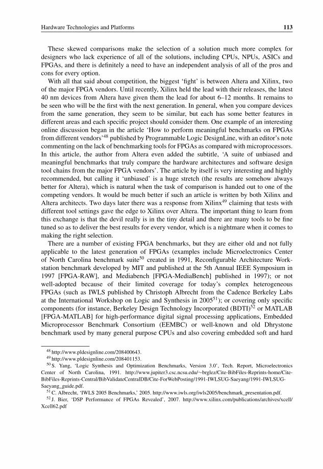
P1: OTA/XYZ P2: ABCc03 BLBK307-Bachmutsky September 2, 2010 13:12 Printer Name: Yet to Come
Hardware Technologies and Platforms 113
These skewed comparisons make the selection of a solution much more complex fordesigners who lack experience of all of the solutions, including CPUs, NPUs, ASICs andFPGAs, and there is definitely a need to have an independent analysis of all of the pros andcons for every option.
With all that said about competition, the biggest ‘fight’ is between Altera and Xilinx, twoof the major FPGA vendors. Until recently, Xilinx held the lead with their releases, the latest40 nm devices from Altera have given them the lead for about 6–12 months. It remains tobe seen who will be the first with the next generation. In general, when you compare devicesfrom the same generation, they seem to be similar, but each has some better features indifferent areas and each specific project should consider them. One example of an interestingonline discussion began in the article ‘How to perform meaningful benchmarks on FPGAsfrom different vendors’48 published by Programmable Logic DesignLine, with an editor’s notecommenting on the lack of benchmarking tools for FPGAs as compared with microprocessors.In this article, the author from Altera even added the subtitle, ‘A suite of unbiased andmeaningful benchmarks that truly compare the hardware architectures and software designtool chains from the major FPGA vendors’. The article by itself is very interesting and highlyrecommended, but calling it ‘unbiased’ is a huge stretch (the results are somehow alwaysbetter for Altera), which is natural when the task of comparison is handed out to one of thecompeting vendors. It would be much better if such an article is written by both Xilinx andAltera architects. Two days later there was a response from Xilinx49 claiming that tests withdifferent tool settings gave the edge to Xilinx over Altera. The important thing to learn fromthis exchange is that the devil really is in the tiny detail and there are many tools to be finetuned so as to deliver the best results for every vendor, which is a nightmare when it comes tomaking the right selection.
There are a number of existing FPGA benchmarks, but they are either old and not fullyapplicable to the latest generation of FPGAs (examples include Microelectronics Centerof North Carolina benchmark suite50 created in 1991, Reconfigurable Architecture Work-station benchmark developed by MIT and published at the 5th Annual IEEE Symposium in1997 [FPGA-RAW], and Mediabench [FPGA-MediaBench] published in 1997); or notwell-adopted because of their limited coverage for today’s complex heterogeneousFPGAs (such as IWLS published by Christoph Albrecht from the Cadence Berkeley Labsat the International Workshop on Logic and Synthesis in 200551); or covering only specificcomponents (for instance, Berkeley Design Technology Incorporated (BDTI)52 or MATLAB[FPGA-MATLAB] for high-performance digital signal processing applications, EmbeddedMicroprocessor Benchmark Consortium (EEMBC) or well-known and old Dhrystonebenchmark used by many general purpose CPUs and also covering embedded soft and hard
48 http://www.pldesignline.com/208400643.49 http://www.pldesignline.com/208401153.50 S. Yang, ‘Logic Synthesis and Optimization Benchmarks, Version 3.0’, Tech. Report, Microelectronics
Center of North Carolina, 1991. http://www.jupiter3.csc.ncsu.edu/∼brglez/Cite-BibFiles-Reprints-home/Cite-BibFiles-Reprints-Central/BibValidateCentralDB/Cite-ForWebPosting/1991-IWLSUG-Saeyang/1991-IWLSUG-Saeyang_guide.pdf.
51 C. Albrecht, ‘IWLS 2005 Benchmarks,’ 2005. http://www.iwls.org/iwls2005/benchmark_presentation.pdf.52 J. Bier, ‘DSP Performance of FPGAs Revealed’, 2007. http://www.xilinx.com/publications/archives/xcell/
Xcell62.pdf

P1: OTA/XYZ P2: ABCc03 BLBK307-Bachmutsky September 2, 2010 13:12 Printer Name: Yet to Come
114 System Design for Telecommunication Gateways
Introduction of
first commercial
RS232
asynchronous
serial interface
(Bell)
1989 ………1969 …1946 1998 2003 2005 2004
First theory of an
asynchronous
computational machine
(Princeton)
Fabrication of first
asynchronous
microprocessor
(Caltech)
Fabrication of fastest
asynchronous
microprocessor (Caltech)
Introduction of first
asynchronous
commercial product
Introduction of fastest
reconfigurable logic
module in CMOS
(Cornell
University/Achronix)
Introduction of first
microprocessor for sensor
networks (Cornell
University/Achronix)
Design of first GHz
asynchronous FPGA
(Achronix)
Introduction of
first commercial
RS232
asynchronous
serial interface
(Bell)
1989 ………1969 …1946 1998 2003 2005 2004
First theory of an
asynchronous
computational machine
(Princeton)
Fabrication of first
asynchronous
microprocessor
(Caltech)
Fabrication of fastest
asynchronous
microprocessor (Caltech)
Introduction of first
asynchronous
commercial product
(Fulcrum Microsystems)
Introduction of fastest
reconfigurable logic
module in CMOS
(Cornell
University/Achronix)
Design of first GHz
asynchronous FPGA
(Achronix)
Introduction of asynchronous
interface logic in next
generation Itanium processor
(Intel)
Figure 3.76 Pre-Achronix asynchronous circuits implementations. Reproduced by Achronix.
processors to assess their integer arithmetic capabilities). It is obvious that the creation of atruly independent and comprehensive FPGA benchmark is way overdue.
There are few FPGA vendors today. We will describe below a number of promising FPGAofferings that should be considered for different types of data processing. Other options that arenot mentioned (but which are sometimes interesting) include Lattice Semiconductor whichoffers some power saving, Abound Logic offering high-density FPGAs, SiliconBlue Tech-nologies offering compact low-cost FPGAs more suitable for handheld devices and hence notdiscussed here and a number of start-ups in a stealth mode and, thus have unclear functionality,target market and differentiation.
3.5.2.1 Achronix FPGAs
Achronix Semiconductor was founded in 2004 by the original developers of asynchronouslogic technology from Cornell University. Asynchronous logic by itself is not new (see Figure3.76 and the Achronix 2005 presentation53), but Achronix was the first company to use it inFPGAs.
Achronix FPGAs are built around the proprietary picoPIPETM technology, the only FPGAtechnology at the time of writing that enables speeds of up to 1.5 GHz (the original plansin 2005 targeted 2.5 GHz by 2008 using a 90 nm process as shown in the abovementionedpresentation, but even the current 1.5 GHz is far ahead of other FPGA vendors). It consists of aconventional I/O Frame (I/O, SerDes, clocks, PLLs, etc.) surrounding a picoPIPE logic fabric,as shown in Figure 3.77. The picoPIPE fabric includes an array of Re-configurable LogicBlocks (RLBs), connected through a programmable fabric. Each RLB contains eight 4-inputLook Up Tables (LUTs) for implementation of combinatorial and sequential logic or 8-bit
53 http://www.klabs.org/richcontent/Misc_Content/meetings/achronix_nov_2005/achronix_nov_2005.ppt.

P1: OTA/XYZ P2: ABCc03 BLBK307-Bachmutsky September 2, 2010 13:12 Printer Name: Yet to Come
Hardware Technologies and Platforms 115
Figure 3.77 Achronix FPGA architecture. Reproduced by Achronix.
dual-port 128 bits 16 × 8 of RAM for implementation of small distributed memory elements.It is surrounded by Switch Boxes (SBs) that route global signals across the picoPIPE fabric.
In addition, the fabric contains dual-port (independent read-write) Block RAMs (18 Kbiteach organized as 16K × 1, 8K × 2, 4K × 4, 2048 × 9, 2048 × 8, 1024 × 18, 1024 × 16,512 × 36, or 512 × 32) and dedicated multipliers (each can be viewed as a single 18 × 18 ora dual 9 × 9) operating at 1.5 GHz to reach the required device performance.
The basic elements of a picoPIPE are the Connection Element (CE), the Functional Element(FE), the Link and the Boundary Elements (BEs). These basic elements can be used to buildthe processing pipeline, as shown in Figure 3.78.
Each stage in the pipeline holds a Data Token, but its meaning is different from other FPGAs.In conventional FPGAs the Data Token refers only to the data itself and some form of datais always present at every point of time at every pipeline stage. Because of data propagationlatencies inside the FPGA logic fabric, such data can be either valid or invalid; therefore,FPGAs rely normally on the clock to signal that the data is valid and can be processed. It
TxRx
Functional Element
Rx TxCombinatorialLogic
Handshaking
Data
Handshaking
Data
TxRx
Functional Element
Rx TxCombinatorialLogic
Handshaking
Data
Handshaking
Data
TxRx
ConnectionElement
ConnectionElement
ConnectionElement
Pipeline Stage Pipeline Stage Pipeline Stage Pipeline Stageds001_03_v02
Pipeline Stage
Link
Tx
Handshaking
Data
Rx
Functional Element
Rx TxCombinatorialLogic
TxRx
ConnectionElement
DQ
Clk
Q
Ingress Egress
QD
Clk
Boundary Elements
ds001_02_v03
Figure 3.78 Achronix building blocks and pipeline stages. Reproduced by Achronix.

P1: OTA/XYZ P2: ABCc03 BLBK307-Bachmutsky September 2, 2010 13:12 Printer Name: Yet to Come
116 System Design for Telecommunication Gateways
Data
Data
CLK
D
Rx Tx Rx Tx Rx Tx Rx Tx Rx Tx
Q D Q D QCombinatorialLogic
CombinatorialLogic
Conventional Logic
picoPIPE Logic
CombinatorialLogic
CombinatorialLogic
CombinatorialLogic
CombinatorialLogic
CombinatorialLogic
CombinatorialLogic
Figure 3.79 Achronix data propagation vs. conventional FPGAs. Reproduced by Achronix.
causes the logic to be similar to that which is shown for conventional logic in the upper partof Figure 3.79, where the clock speed must run no faster than the propagation delay of thelongest path in the entire clock domain, which limits the effective clock rate. It is possible tocreate multiple clock domains to minimize the problem, but there is a practical limitation tosuch a technique.
In the Achronix architecture, the clock is not global, it is local between pipeline stages, andthus the Data Token can be viewed as the entity that consists of both data and clock, enablingmuch higher clock speeds.
An additional advantage of the Achronix architecture is the ease of making modifications tothe existing implementation. Regular FPGAs require the addition of new data synchronizationlogic, recalculating clock rates or reevaluating a number of clock domains. In Achronix-baseddesign the procedure is much simpler, because a new stage can simply be dropped into therequired location without affecting the rest of the system, except for an unavoidable increaseof total latency when the affected pipeline is in the system bottleneck path.
Achronix BEs are used only at the border between the FPGA Frame and the logic translatingthe Data Tokens for both ingress and egress paths. FEs are relatively ‘conventional’ elementsthat provide the combinatorial computation with the only difference being in the ingress andegress communication mechanism, which includes a handshaking protocol to ensure that onlyvalid data is propagated to the next stage. On the other hand, CEs are totally different with theirunique capability of being initialized as either state-holding (similar to the register) or stateless(similar to the repeater) enabling both connectivity and storage needs. Having the capabilityto initialize CEs in a stateless state provides the flexibility of adding a new intermediatestage without affecting any existing logic. Of course, the status can change for any CE as theprocessing proceeds through the pipeline.
The physical layout could become simpler with Achronix architecture, because in manycases it will enable much shorter interconnects, as shown in Figure 3.80.
One of the biggest advantages of Achronix FPGAs is their relatively high speed and thustheir capability of handling very complex designs. Today, it might be the best candidate fora FPGA-based solution to achieve complex high-throughput packet processing, because in
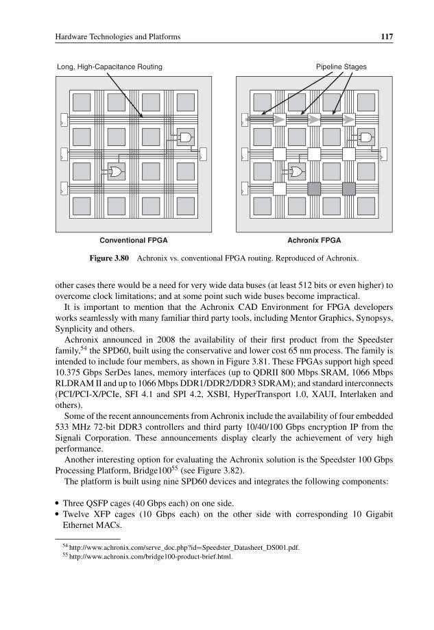
P1: OTA/XYZ P2: ABCc03 BLBK307-Bachmutsky September 2, 2010 13:12 Printer Name: Yet to Come
Hardware Technologies and Platforms 117
Conventional FPGA Achronix FPGA
Long, High-Capacitance Routing Pipeline Stages
Figure 3.80 Achronix vs. conventional FPGA routing. Reproduced of Achronix.
other cases there would be a need for very wide data buses (at least 512 bits or even higher) toovercome clock limitations; and at some point such wide buses become impractical.
It is important to mention that the Achronix CAD Environment for FPGA developersworks seamlessly with many familiar third party tools, including Mentor Graphics, Synopsys,Synplicity and others.
Achronix announced in 2008 the availability of their first product from the Speedsterfamily,54 the SPD60, built using the conservative and lower cost 65 nm process. The family isintended to include four members, as shown in Figure 3.81. These FPGAs support high speed10.375 Gbps SerDes lanes, memory interfaces (up to QDRII 800 Mbps SRAM, 1066 MbpsRLDRAM II and up to 1066 Mbps DDR1/DDR2/DDR3 SDRAM); and standard interconnects(PCI/PCI-X/PCIe, SFI 4.1 and SPI 4.2, XSBI, HyperTransport 1.0, XAUI, Interlaken andothers).
Some of the recent announcements from Achronix include the availability of four embedded533 MHz 72-bit DDR3 controllers and third party 10/40/100 Gbps encryption IP from theSignali Corporation. These announcements display clearly the achievement of very highperformance.
Another interesting option for evaluating the Achronix solution is the Speedster 100 GbpsProcessing Platform, Bridge10055 (see Figure 3.82).
The platform is built using nine SPD60 devices and integrates the following components:
� Three QSFP cages (40 Gbps each) on one side.� Twelve XFP cages (10 Gbps each) on the other side with corresponding 10 Gigabit
Ethernet MACs.
54 http://www.achronix.com/serve_doc.php?id=Speedster_Datasheet_DS001.pdf.55 http://www.achronix.com/bridge100-product-brief.html.
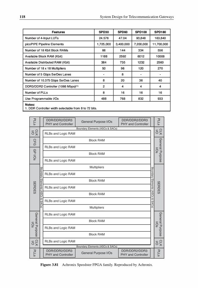
P1: OTA/XYZ P2: ABCc03 BLBK307-Bachmutsky September 2, 2010 13:12 Printer Name: Yet to Come
118 System Design for Telecommunication Gateways
Block RAM
Block RAM
Block RAM
Block RAM
Block RAM
Block RAM
Multipliers
Multipliers
Boundary E
lements (A
SC
s & S
AC
s)
Boundary E
lements (A
SC
s & S
AC
s)
Boundary Elements (ASCs & SACs)
Boundary Elements (ASCs & SACs)
RLBs and Logic RAM
RLBs and Logic RAM
RLBs and Logic RAM
RLBs and Logic RAM
RLBs and Logic RAM
RLBs and Logic RAM
RLBs and Logic RAM
RLBs and Logic RAM
RLBs and Logic RAM
DDR/DDR2/DDR3PHY and Controller
DDR/DDR2/DDR3PHY and Controller
DDR/DDR2/DDR3PHY and Controller
DDR/DDR2/DDR3PHY and Controller
SE
RD
ES
PLLs
PLLs
PLLs
General P
urposeI/O
sG
eneral Purpose
I/Os
CLK
I/OC
LKI/O
General Purpose I/Os
CF
GS
ER
DE
SP
LLs General Purpose I/Os
General P
urposeI/O
sG
P I/O
sC
LKI/O
CLK
I/O
Notes:1. DDR Controller width selectable from 8 to 72 bits.
933832768488Use Programmable I/Os
1616168Number of PLLs
4442DDR3/DDR2 Controller (1066 Mbps)(1)
4036208Number of 10.375 Gbps SerDes Lanes
--8-Number of 5 Gbps SerDes Lanes
2701209850Number of 18 x 18 Multipliers
25601232735384Available Distributed RAM (Kbit)
10008601225921188Available Block RAM (Kbit)
55633414466Number of 18 Kbit Block RAMs
11,700,0007,200,0003,400,0001,725,000picoPIPE Pipeline Elements
163,84093,84847.0424.576Number of 4-Input LUTs
SPD180SPD100SPD60SPD30Features
Figure 3.81 Achronix Speedster FPGA family. Reproduced by Achronix.

P1: OTA/XYZ P2: ABCc03 BLBK307-Bachmutsky September 2, 2010 13:12 Printer Name: Yet to Come
Hardware Technologies and Platforms 119
Figure 3.82 Achronix Speedster 100 Gbps Processing Platform Bridge100 Block Diagram. Repro-duced by Achronix.
� An additional eight-lane port is provided (up to 80 Gbps bidirectional) as an optional controlpath or for exception processing.
� 40 Gbps inter-chip connect.� 8 GB DDR3 SDRAM (eight modules 128M × 64 each) with total 614 Gbps raw DDR3
bandwidth.� 3 Mb of embedded RAM per device or total 29.7 Mb per system.� Cypress CY7C1565V18 QDRII+ SRAM (2M 36).� NetLogic NL91024 TCAM search engine.� A Computer-on-Module, CompuLab’s CM-X270, for general control and administrative
functions with 16 MB SDRAM and 1 MB of flash memory.
Production of 100 Gbps processing with this solution is probably not the target, it is usefulmainly for evaluation purposes and will be replaced with a higher density parts when theybecome available.
3.5.2.2 Altera FPGAs
Altera is one of the two largest FPGA manufacturers and offers a variety of different productssuitable for different applications. As of the time of writing, their latest and fastest device isthe Stratix IV.56
56 Refer to the Altera website (http://www.altera.com) for the most recent documentation or information.
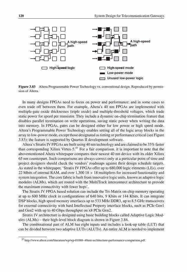
P1: OTA/XYZ P2: ABCc03 BLBK307-Bachmutsky September 2, 2010 13:12 Printer Name: Yet to Come
120 System Design for Telecommunication Gateways
A high-speed path
A high-speed path
edom deeps-hgiHci gol d e e ps - hgiH
Low-power mode
Unused low-power logic
e-hi l d e e s -
Figure 3.83 Altera Programmable Power Technology vs. conventional design. Reproduced by permis-sion of Altera.
In many designs FPGAs need to focus on power and performance; and in some cases toeven trade off between them. For example, Altera’s 40 nm FPGAs are implemented withmultiple-gate oxide thicknesses (triple oxide) and multiple-threshold voltages, which tradestatic power for speed per transistor. They include a dynamic on-chip termination feature thatdisables parallel termination on write operations, saving static power when writing the datainto memory. In FPGAs, gates can be designed either for low power or high speed mode.Altera’s Programmable Power Technology enables setting all of the logic array blocks in thearray to low-power mode, except those designated as timing or performance critical (see Figure3.83); the feature is supported by Quartus II development software.
Altera’s Stratix IV FPGAs are built using 40 nm technology and are claimed to be 35% fasterthan corresponding Xilinx Virtex-5.57 For a fair comparison, it is important to note that theabovementioned Altera whitepaper compares their newest 40 nm device with its older Xilinx65 nm counterpart. Such comparisons are always correct only at a particular point of time andproject designers should check the vendors’ roadmaps against their design schedule targets.As stated in the whitepaper, ‘Stratix IV FPGAs offer up to 680,000 logic elements (LEs), over22 Mbits of internal RAM, and over 1,300 18 × 18 multipliers for increased functionality andsystem integration. The core fabric is built from innovative logic units, known as adaptive logicmodules (ALMs), which are routed with the MultiTrack interconnect architecture to providethe maximum connectivity with fewer hops’.
The Stratix IV FPGA based solution can include the Tri-Matrix on-chip memory operatingat up to 600 MHz clock in configurations of 640 bits, 9 Kbits or 144 Kbits. It can integrateDSP blocks, high speed memory interfaces up to 533 MHz DDR3, up to 8.5 GHz transceiversfor external connectivity with hard Intellectual Property interface blocks, such as PCIe Gen1and Gen2 with up to 40 Gbps throughput on x8 PCIe Gen2.
Stratix IV architecture is designed using basic building blocks called Adaptive Logic Mod-ules (ALMs) – their high-level block diagram is shown in Figure 3.84.
The combinational part of ALM has eight inputs and includes a look-up table (LUT) thatcan be divided between two adaptive LUTs (ALUTs). An entire ALM is needed to implement
57 http://www.altera.com/literature/wp/wp-01088–40nm-architecture-performance-comparison.pdf.

P1: OTA/XYZ P2: ABCc03 BLBK307-Bachmutsky September 2, 2010 13:12 Printer Name: Yet to Come
Hardware Technologies and Platforms 121
shared_arith_in
dataf0
datae0 6-Input LUT adder0 D Q
reg0
D Q
reg1
adder16-Input LUT
dataa
datab
datac
datad
datae1
dataf1
Combinational/Memory ALUT0
Combinational/Memory ALUT1
carry_in reg_chain_in
shared_arith_out carry_out
reg_chain_out
labclk
To general orlocal routing
To general orlocal routing
To general orlocal routing
To general orlocal routing
Figure 3.84 High-Level Block Diagram of the Altera Stratix IV ALM. Reproduced by permission ofAltera.
an arbitrary six-input function, but one ALM can implement various combinations of the twofunctions: for example, two independent four-input functions or a five-input and a three-inputfunction with independent inputs, or four-input and five-input functions with one shared input,or two five-input functions with two shared inputs, or two six-input functions with four sharedinputs and the same combinational functions. In addition to the adaptive LUT-based resources,each ALM contains two programmable registers, two dedicated full adders, a carry chain, ashared arithmetic chain and a register chain, enabling implementation of various arithmeticfunctions and shift registers.
Each ALM has two sets of outputs and implements the register packing functionality withthe capability of LUT or adder to drive one set of outputs and with the register driving anotherset, simultaneously improving device utilization.
In addition to the normal ALM mode described above, Stratix IV also supports the ExtendedLUT mode for a seven-input function implementation with two five-input LUTs, four sharedinputs and an extra input being available optionally for register packing.
There are three other ALM modes – arithmetic, shared arithmetic and LUT-register (seeFigure 3.85). ALM in arithmetic mode uses two sets of two four-input LUTs along with twodedicated full adders (each adder can add the output of two four-input functions), making itideal for implementing adders, counters, accumulators and comparators. In shared arithmeticmode the ALM can implement three-input addition operations. Two internal feedback loopsenable combinational ALUT1 to implement the master latch and combinational ALUT0to implement the slave latch required for the third register. Therefore, for implementationrequiring three registers in a single ALM, the LUT-Register mode can be used.
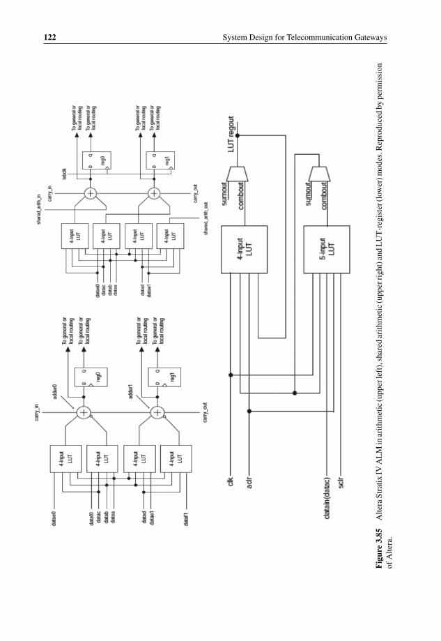
P1: OTA/XYZ P2: ABCc03 BLBK307-Bachmutsky September 2, 2010 13:12 Printer Name: Yet to Come
122 System Design for Telecommunication Gateways
Fig
ure
3.85
Alte
raSt
ratix
IVA
LM
inar
ithm
etic
(upp
erle
ft),
shar
edar
ithm
etic
(upp
erri
ght)
and
LU
T-r
egis
ter(
low
er)m
odes
.Rep
rodu
ced
bype
rmis
sion
ofA
ltera
.
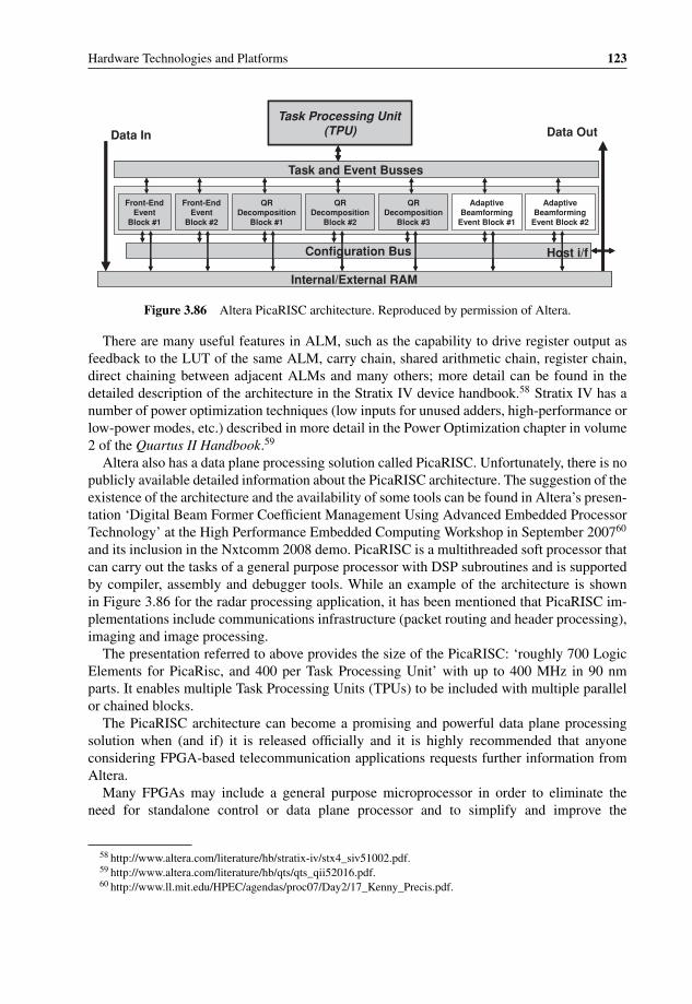
P1: OTA/XYZ P2: ABCc03 BLBK307-Bachmutsky September 2, 2010 13:12 Printer Name: Yet to Come
Hardware Technologies and Platforms 123
Task Processing Unit (TPU)
Task and Event Busses
Front-End Event
Block #1
Front-End Event
Block #2
QRDecomposition
Block #1
QRDecomposition
Block #2
QRDecomposition
Block #3
Adaptive Beamforming
Event Block #1
Adaptive Beamforming
Event Block #2
Configuration Bus
Internal/External RAM
Data In Data Out
Host i/f
Task Processing Unit (TPU)
Task and Event Busses
Front-End Event
Block #1
Front-End Event
Block #2
QRDecomposition
Block #1
QRDecomposition
Block #2
QRDecomposition
Block #3
Adaptive Beamforming
Event Block #1
Adaptive Beamforming
Event Block #2
Configuration Bus
Internal/External RAM
Host i/f
Figure 3.86 Altera PicaRISC architecture. Reproduced by permission of Altera.
There are many useful features in ALM, such as the capability to drive register output asfeedback to the LUT of the same ALM, carry chain, shared arithmetic chain, register chain,direct chaining between adjacent ALMs and many others; more detail can be found in thedetailed description of the architecture in the Stratix IV device handbook.58 Stratix IV has anumber of power optimization techniques (low inputs for unused adders, high-performance orlow-power modes, etc.) described in more detail in the Power Optimization chapter in volume2 of the Quartus II Handbook.59
Altera also has a data plane processing solution called PicaRISC. Unfortunately, there is nopublicly available detailed information about the PicaRISC architecture. The suggestion of theexistence of the architecture and the availability of some tools can be found in Altera’s presen-tation ‘Digital Beam Former Coefficient Management Using Advanced Embedded ProcessorTechnology’ at the High Performance Embedded Computing Workshop in September 200760
and its inclusion in the Nxtcomm 2008 demo. PicaRISC is a multithreaded soft processor thatcan carry out the tasks of a general purpose processor with DSP subroutines and is supportedby compiler, assembly and debugger tools. While an example of the architecture is shownin Figure 3.86 for the radar processing application, it has been mentioned that PicaRISC im-plementations include communications infrastructure (packet routing and header processing),imaging and image processing.
The presentation referred to above provides the size of the PicaRISC: ‘roughly 700 LogicElements for PicaRisc, and 400 per Task Processing Unit’ with up to 400 MHz in 90 nmparts. It enables multiple Task Processing Units (TPUs) to be included with multiple parallelor chained blocks.
The PicaRISC architecture can become a promising and powerful data plane processingsolution when (and if) it is released officially and it is highly recommended that anyoneconsidering FPGA-based telecommunication applications requests further information fromAltera.
Many FPGAs may include a general purpose microprocessor in order to eliminate theneed for standalone control or data plane processor and to simplify and improve the
58 http://www.altera.com/literature/hb/stratix-iv/stx4_siv51002.pdf.59 http://www.altera.com/literature/hb/qts/qts_qii52016.pdf.60 http://www.ll.mit.edu/HPEC/agendas/proc07/Day2/17_Kenny_Precis.pdf.

P1: OTA/XYZ P2: ABCc03 BLBK307-Bachmutsky September 2, 2010 13:12 Printer Name: Yet to Come
124 System Design for Telecommunication Gateways
System Concept
Analyze System Requirements
Define and Generate System in SOPC Builder
Nios II Cores and Standard
Components
Custom Instruction and
Peripheral Logic
Integrate SOPC Builder System into
Quartus II Project
Hardware Flow
Select SW Flow
IDE SW FlowSoftware Build
Tools Flow
Assign Pin Locations, Timing Requirements, and
Other Design Constraints
Compile Hardware for Target
Develop Software with the Nios II
IDE
Download SW to NiosII system on Target
Board with the Nios II IDE
Build the System Library and
Application Projects with the Nios II IDE
Develop SW directly with the Software build
tools
Build the BSP and Application Projects
with the Software Build Tools
Download SW to Nios II System on
Target Board using nios2-download
AlteraHardware
Abstraction Layer and Peripheral
Drivers
User C/C++ Application Code and Custom Libraries
Run/Debug Software on Target Board
Refine Software and Hardware
Meets Spec?No
Yes
Code Complete
Custom Hardware Modules
Download FPGA Design to Target
Board
Figure 3.87 FPGA System Design Flow for Nios II using Altera SOPC Builder. Reproduced bypermission of Altera.
performance of communication between control and data planes. Altera offers Nios II softprocessors, which can be placed anywhere in FPGA. One of the biggest advantages of modernFPGA-based design is the flexibility to choose between discrete system components, softwareand hardware. This flexibility adds, of course, complexity. Therefore, Altera provides theSystem on a Programmable Chip (SOPC) Builder design tool (see Figure 3.87 for a system de-sign flow diagram) to offload the major elements of complexity from designers, including themodification or addition of the instruction set, interfaces, caches and many other parametersat any point of time depending on applications and algorithm modifications. SOPC Builderalso facilitates the capability to move some parts of the algorithms into the hardware in orderto improve performance. The C-to-hardware (C2H) compiler can be used for that purpose.
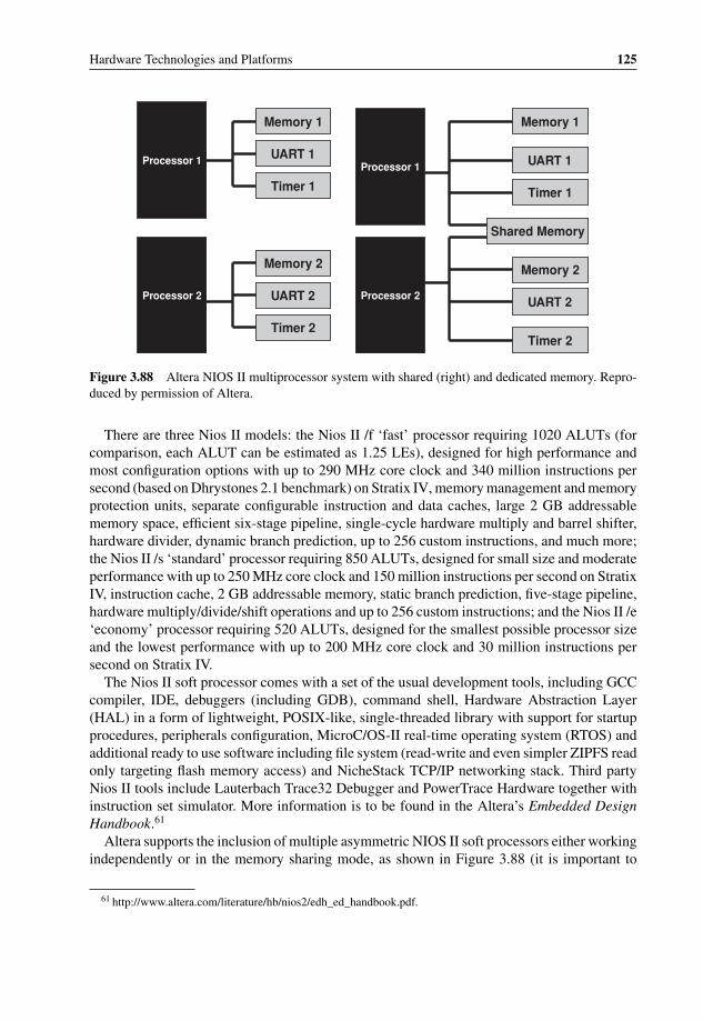
P1: OTA/XYZ P2: ABCc03 BLBK307-Bachmutsky September 2, 2010 13:12 Printer Name: Yet to Come
Hardware Technologies and Platforms 125
Processor 1Processor 1
Processor 2 Processor 2
Memory 1
Memory 2
Memory 1
Memory 2
UART 1 UART 1
UART 2 UART 2
Timer 1 Timer 1
Timer 2Timer 2
Shared Memory
Figure 3.88 Altera NIOS II multiprocessor system with shared (right) and dedicated memory. Repro-duced by permission of Altera.
There are three Nios II models: the Nios II /f ‘fast’ processor requiring 1020 ALUTs (forcomparison, each ALUT can be estimated as 1.25 LEs), designed for high performance andmost configuration options with up to 290 MHz core clock and 340 million instructions persecond (based on Dhrystones 2.1 benchmark) on Stratix IV, memory management and memoryprotection units, separate configurable instruction and data caches, large 2 GB addressablememory space, efficient six-stage pipeline, single-cycle hardware multiply and barrel shifter,hardware divider, dynamic branch prediction, up to 256 custom instructions, and much more;the Nios II /s ‘standard’ processor requiring 850 ALUTs, designed for small size and moderateperformance with up to 250 MHz core clock and 150 million instructions per second on StratixIV, instruction cache, 2 GB addressable memory, static branch prediction, five-stage pipeline,hardware multiply/divide/shift operations and up to 256 custom instructions; and the Nios II /e‘economy’ processor requiring 520 ALUTs, designed for the smallest possible processor sizeand the lowest performance with up to 200 MHz core clock and 30 million instructions persecond on Stratix IV.
The Nios II soft processor comes with a set of the usual development tools, including GCCcompiler, IDE, debuggers (including GDB), command shell, Hardware Abstraction Layer(HAL) in a form of lightweight, POSIX-like, single-threaded library with support for startupprocedures, peripherals configuration, MicroC/OS-II real-time operating system (RTOS) andadditional ready to use software including file system (read-write and even simpler ZIPFS readonly targeting flash memory access) and NicheStack TCP/IP networking stack. Third partyNios II tools include Lauterbach Trace32 Debugger and PowerTrace Hardware together withinstruction set simulator. More information is to be found in the Altera’s Embedded DesignHandbook.61
Altera supports the inclusion of multiple asymmetric NIOS II soft processors either workingindependently or in the memory sharing mode, as shown in Figure 3.88 (it is important to
61 http://www.altera.com/literature/hb/nios2/edh_ed_handbook.pdf.

P1: OTA/XYZ P2: ABCc03 BLBK307-Bachmutsky September 2, 2010 13:12 Printer Name: Yet to Come
126 System Design for Telecommunication Gateways
remember that Altera does not support sharing of non-memory resources between multipleNIOS II processors in the system and that this restriction includes external ports).
The shared memory mode has, of course, its disadvantages chief amongst which is thepossibility of memory corruption when multiple processors write into the same memoryaddress simultaneously or one processor writes and other processor(s) read from the samelocation at the same time. To protect the system, Altera offers hardware mutex capability asa SOPC Builder component, which enables ‘negotiation’ of mutually exclusive access to ashared resource. In practice, the mutex is an additional shared resource providing an atomictest-and-set operation similar to many general purpose CPUs: a processor can test if the mutexis unlocked and in the case of availability to perform the mutex lock, all in a single operation.
3.5.2.3 Xilinx FPGAs
Xilinx is another major FPGA vendor. It offers two main series of devices: higher performanceVirtex R© and lower cost Spartan R©. Table 3.3 provides a comparison of features between thelatest Virtex-6 and the previous generation of Virtex-5 and Spartan-6 FPGAs.
The low-power 45 nm Spartan-6 family includes two sub-families: LX and LXT. LXTFPGAs add integrated transceivers and PCI Express endpoint block on top of the other featuresincluded in LX sub-family. On the other hand, the LX sub-family can operate on a lower 1 Vcore power for significantly reduced power consumption. All of the devices have flexiblesix-input LUTs with dual flip-flops for pipelined applications. LUTs are configurable as logic,distributed RAM, or shift registers.
Virtex-5 is built using 65 nm technology and 1.0 V core voltage. It includes five sub-families of devices: LX for high performance logic; LXT for high-performance logic with lowpower serial connectivity; SXT for DSP and memory-intensive applications with low-powerserial connectivity; FXT for embedded processing with highest-speed serial connectivity; andTXT for high-bandwidth telecommunication applications, such as bridging, switching andaggregation.
Virtex-6 is built using 40 nm copper CMOS technology. It operates on a 1.0 V core voltagewith an available 0.9 V low-power option. Virtex-6 includes three sub-families of devices: LXTsub-family for applications that require high-performance logic, DSP, and serial connectivitywith low-power GTX 6.5Gbps serial transceivers; SXT sub-family for applications that requireultra-high DSP performance and serial connectivity with low-power GTX 6.5Gbps serialtransceivers; HXT sub-family for communications applications with the highest-speed serialconnectivity achieved by a combination of up to 72 GTX transceivers and the new GTHtransceivers that support line rates in excess of 11 Gbps. Devices support six-input LUTs withdual-output five-input LUT option.
There are many companies offering blades and even ready-made platforms based on XilinxFPGAs. One them is the BEEcube offering the 2U rack mounted BEE3 system developedjointly by Microsoft Research, UC Berkeley and BEEcube Inc. The 400 W system is builtusing four large Virtex-5 LXT/SXT/FXT FPGA chips with over 4 trillion integer operationsper second in total, up to 64 GB DDR2 DRAM, up to four x8 PCI Express connections forhigh-speed connectivity to host servers, eight 10 GBase-CX4 (10 Gigabit Ethernet) interfaces,and direct 160 LVDS high-speed connections to external multi-GHz analog converter devices,such as ADC and DAC. To showcase the system’s capabilities, the BEEcube has implemented

P1: OTA/XYZ P2: ABCc03 BLBK307-Bachmutsky September 2, 2010 13:12 Printer Name: Yet to Come
Hardware Technologies and Platforms 127
Table 3.3 Xilinx FPGAs – Comparison of features. Reproduced by permission of Xilinx Inc.
Features Virtex-6 Virtex-5 Spartan-6
Logic Cells Up to 760 000 Up to 330,000 From 3800 to 147 000User I/Os Up to 1200 Up to 1200 Up to 570
Clock ManagementTechnology
600 MHz clockingtechnology withnew Phase-LockedLoops(PLLs)-basedmixed-mode clockmanagers for lowjitter and jitterfiltering; mid-pointbuffering reducesskew and jitter
550 MHz clockingtechnology withtwo Digital ClockManagers (DCMs)to eliminate clockskew and dutycycle distortionand Phase-LockedLoops (PLLs) forlow jitter clocking
1050 MHz clockingtechnology with DigitalClock Managers(DCMs) to eliminateclock skew and dutycycle distortion andPhase-Locked Loops(PLLs) for low jitterclocking
Embedded BlockRAM
Up to 38 Mbits;600 MHz, 36 Kbitblock RAM thatcan be split intotwo 18 Kbit blocks
Up to 18 Mbits;550 MHz, 36 Kbitblock RAM thatcan be split intotwo 18 Kbit blocks
Up to 4.8 Mbits; fastblock RAM withbyte write enable;18 Kb blocks that canbe split into twoindependent 9 Kbblock RAMs
EmbeddedMultipliers forDSP
up to 2016 600 MHzDSP48E1 slices,each slice containsa 25-bit pre-adder,25x18 multiplier,48-bit adder, and48-bit accumulator(cascadable to96 bits); more than1000 GMACS totalperformance
550 MHz DSP48Eslices, 25x18MAC; 1.38mW/100 MHz
Up to 180 EfficientDSP48A1 Slices, eachslice contains 18x18multiplier and a48-bit accumulatorcapable of operatingat 250 MHzy; pipeliningand cascadingcapability; pre-adderto assist in symmetricfilter applications
Multi-Gigabit HighSpeed Serial
GTX transceivers runat 150 Mbps to6.5 Gbps with<150 mW (typical)at 6.5 Gbps; GTHtransceivers withline rates beyond11 Gbps to enable40 G and 100 Gprotocols and morewith ∼220 mW(typical) at10.3125 Gbps; upto four integratedEthernet10/100/1000/2500MACs
3.75 Gbps, 6.5 Gbps;up to eightintegratedEthernet10/100/1000MACs
3.125 Gbps, < 150 mW(typical) at 3.125 GHz;high-speed interfaces:Serial ATA, Aurora,1G Ethernet, PCIExpress, OBSAI, CPRI,EPON, GPON,DisplayPort, and XAUI

P1: OTA/XYZ P2: ABCc03 BLBK307-Bachmutsky September 2, 2010 13:12 Printer Name: Yet to Come
128 System Design for Telecommunication Gateways
Table 3.3 (Continued)
Features Virtex-6 Virtex-5 Spartan-6
PCI Express R©Technology
Up to four PCIeblocks; Gen 1,x1/x2/x4/x8, hard;Gen 2,x1/x2/x4/x8, hard;
Up to four PCIeblocks; Gen 1,x1/x4/x8, hard Gen2, x1/x4/x8, soft
Gen 1, x1, hard
Processor Yes FXT sub-family only:up to two PowerPC440 processorswith 32-bit RISCcores, 1100 DMIPSper processor
MicroBlaze 7.0 with MMUand FPU
Integrated MemoryControllers
Interface tohigh-performanceexternal memoriessuch as DDR3,QDR II+,RLDRAM, andmore; configureSelectIOTM pins tosupport HSTL,LVDS (SDR andDDR), and more, atvoltages from 1.0V to 2.5 V
DDR, DDR2, DDR3, andLPDDR support; Datarates up to 800 Mbps(12.8 Gbps peakbandwidth)
in the BEE3 system full quad-core OpenSPARC T1 processor emulation with four hardwarethreads per core, including inter-core crossbar, L2 cache and other T1 components and binary-compatible OpenSolaris or Ubuntu Linux operating system.
3.5.2.4 FPGA and GPCPU Hybrids
FPGAs are used frequently to offload some computational tasks from the main CPU, thuscreating the field of high performance reconfigurable computing (HPRC). With most currentimplementations being outside of the telecommunications industry, the technology can behighly relevant for some of these products.
One example are the FPGA Reconfigurable Processor Units (RPUs) from the DRCComputer Corporation (acquired by Security First Corp. in June 2009). Supercomputermanufacturer Cray Inc.’s XT5h system (similar to the previously available XD1 system)includes a hybrid blade with the DRC-based acceleration model RPU110-L200 with a Virtex-4 LX200 device from Xilinx. The latest DRC FPGA Accelium co-processor (see Figure 3.89)uses Xilinx Virtex-5 FPGA with up to 330 000 logic cells and 576x18 Kbits Block RAMs.
It plugs directly into an open processor socket in a multi-way AMD OpteronTM system (seeFigure 3.90) allowing for direct access to the memory and any adjacent Opteron processor at
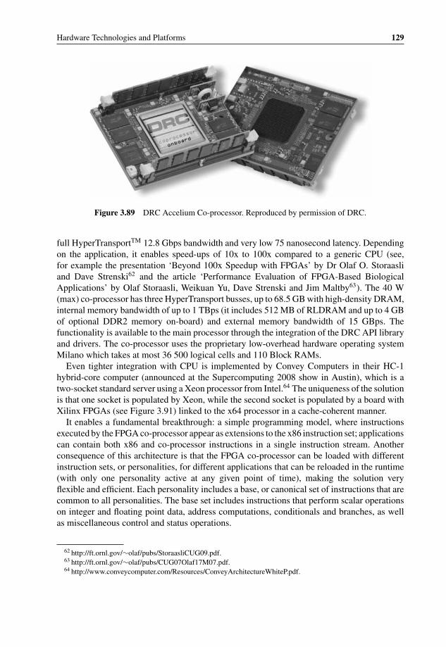
P1: OTA/XYZ P2: ABCc03 BLBK307-Bachmutsky September 2, 2010 13:12 Printer Name: Yet to Come
Hardware Technologies and Platforms 129
Figure 3.89 DRC Accelium Co-processor. Reproduced by permission of DRC.
full HyperTransportTM 12.8 Gbps bandwidth and very low 75 nanosecond latency. Dependingon the application, it enables speed-ups of 10x to 100x compared to a generic CPU (see,for example the presentation ‘Beyond 100x Speedup with FPGAs’ by Dr Olaf O. Storaasliand Dave Strenski62 and the article ‘Performance Evaluation of FPGA-Based BiologicalApplications’ by Olaf Storaasli, Weikuan Yu, Dave Strenski and Jim Maltby63). The 40 W(max) co-processor has three HyperTransport busses, up to 68.5 GB with high-density DRAM,internal memory bandwidth of up to 1 TBps (it includes 512 MB of RLDRAM and up to 4 GBof optional DDR2 memory on-board) and external memory bandwidth of 15 GBps. Thefunctionality is available to the main processor through the integration of the DRC API libraryand drivers. The co-processor uses the proprietary low-overhead hardware operating systemMilano which takes at most 36 500 logical cells and 110 Block RAMs.
Even tighter integration with CPU is implemented by Convey Computers in their HC-1hybrid-core computer (announced at the Supercomputing 2008 show in Austin), which is atwo-socket standard server using a Xeon processor from Intel.64 The uniqueness of the solutionis that one socket is populated by Xeon, while the second socket is populated by a board withXilinx FPGAs (see Figure 3.91) linked to the x64 processor in a cache-coherent manner.
It enables a fundamental breakthrough: a simple programming model, where instructionsexecuted by the FPGA co-processor appear as extensions to the x86 instruction set; applicationscan contain both x86 and co-processor instructions in a single instruction stream. Anotherconsequence of this architecture is that the FPGA co-processor can be loaded with differentinstruction sets, or personalities, for different applications that can be reloaded in the runtime(with only one personality active at any given point of time), making the solution veryflexible and efficient. Each personality includes a base, or canonical set of instructions that arecommon to all personalities. The base set includes instructions that perform scalar operationson integer and floating point data, address computations, conditionals and branches, as wellas miscellaneous control and status operations.
62 http://ft.ornl.gov/∼olaf/pubs/StoraasliCUG09.pdf.63 http://ft.ornl.gov/∼olaf/pubs/CUG07Olaf17M07.pdf.64 http://www.conveycomputer.com/Resources/ConveyArchitectureWhiteP.pdf.

P1: OTA/XYZ P2: ABCc03 BLBK307-Bachmutsky September 2, 2010 13:12 Printer Name: Yet to Come
130 System Design for Telecommunication Gateways
DRC Milano Integration
Environment
HyperTransport Bus
User Application
DRC API Library
DRC RPU Driver
X86 CPU
Accelerated User Application Routines
DRC Hardware OS
DRC Accelium
DRC Milano Integration
Environment
HyperTransport Bus
User Application
DRC API Library
DRC RPU Driver
X86 CPU
Accelerated User Application Routines
DRC Hardware OS
DRC Accelium
Figure 3.90 DRC Accelium Integration with CPU. Reproduced by permission of DRC.
The high bandwidth memory subsystem is shared between Xeon and FPGA and is based oneight memory controllers, supporting sixteen DDR2 memory channels, with a total bandwidthof up to 80 GBytes/sec (see Figure 3.92). In addition, the memory system operates on individualwords as opposed to the whole cache line.
The FPGA has three major sets of components, referred to as the Application Engine Hub(AEH), the Memory Controllers (MCs) and four Application Engines (AEs) – see Figure 3.93.AEH and MCs are the common part for any personality. AEs are connected to the AEH bya command bus which transfers opcodes and scalar operands and is connected in a full meshconfiguration to all MCs. Each AE instruction is passed to all four AEs and the processing isleft to the implementation of personality.
The AEH implements the interface to the host processor and to the Intel I/O chipset, fetchesand decodes instructions, executes Convey canonical instructions (extended instructions arepassed to the AEs), processes coherence and data requests from the host processor and routing
Figure 3.91 Convey FPGA co-processor board. Reproduced by permission of Convey.

P1: OTA/XYZ P2: ABCc03 BLBK307-Bachmutsky September 2, 2010 13:12 Printer Name: Yet to Come
Hardware Technologies and Platforms 131
Figure 3.92 Convey CPU-FPGA hybrid-core architecture. Reproduced by permission of Convey.
Figure 3.93 Convey FPGA co-processor block diagram. Reproduced by permission of Convey.

P1: OTA/XYZ P2: ABCc03 BLBK307-Bachmutsky September 2, 2010 13:12 Printer Name: Yet to Come
132 System Design for Telecommunication Gateways
Figure 3.94 Stack of Intel QuickAssist compliant FPGA accelerators from Nallatech. Reproduced bypermission of Nallatech.
requests for addresses in co-processor memory to the MCs. The MCs translate virtual tophysical addresses on behalf of the AEs and include snoop filters in order to minimize snooptraffic to the host processor. They support standard DIMMs as well as Convey designedScatter-Gather DIMMs, which are optimized for transfers of 8-byte bursts, and provide nearpeak bandwidth for non-sequential 8-byte accesses.
Application development, including coding, debugging and deployment, takes place usingstandard FORTRAN, C, and C++ development tools under Convey-enhanced Linux OS; thetools are derived from the Open64 compiler set that is available for x86, Itanium and otherprocessors.
Convey is not the only vendor implementing FPGA-based acceleration for Intel processors.Nallatech offers FPGA hardware acceleration boards using standard Intel socket and utilizingFront Side Bus (FSB) and Intel’s QuickAssist technology (see Section 3.5.6.2.5). Nallatechenables building a stackable acceleration unit (see Figure 3.94) using three types of module: aFSB Base module that is built using a single Xilinx Virtex-5 FPGA and which plugs directlyinto the Intel Xeon socket and is responsible for handling low level FSB interface; a FSBCompute module (multiple – can be stacked if needed) built with dual Xilinx Virtex-5 FPGAsand four banks of DDR2 SRAM; and a FSB Expansion module that utilizes a single XilinxVirtex-5 FPGA with four banks of QDR-II SRAM, two off-module GTP connectors to supportexternal interfaces, such as PCI Express, Serial RapidIO port, Aurora, and Ethernet, and twooff-module digital connectors with single-ended or LVDS I/O.
Nallatech has also announced that FPGA-based acceleration support for Intel’s new Quick-Path Interconnect.
3.5.2.5 Different ASIC Technologies
There are a number of ASIC technologies. In the full custom ASIC design the developerscontrol everything up to and including every transistor, all of the layers are carefully designed

P1: OTA/XYZ P2: ABCc03 BLBK307-Bachmutsky September 2, 2010 13:12 Printer Name: Yet to Come
Hardware Technologies and Platforms 133
and optimized. The procedure is lengthy, complex and expensive, but provides the best priceand performance, making it the best technology for very high volume chips.
The next step is the standard cell, where ASIC vendors create a library of cells representingsome logical function (logical gate, register or even more complex functions) which are usedby the chip developers to create custom device layers.
The step in the technology after the standard cell is the gate array, where the ASICvendor pre-fabricates silicon layers with arrays of unconnected components (transistors andresistors) and the chip designers create a custom metal layer that connects all of these com-ponents in the way required for a particular functionality. Obviously, this is less efficientcompared to standard cell or custom ASIC, but is a simpler, faster and cheaper designalternative.
Structured or sometimes called platform ASICs are positioned between FPGAs and standardASICs. They offer a significant reduction in design and manufacturing cycle times comparedto cell-based ASICs. The shortening of the design cycle comes from the pre-characterizationof the silicon content; and the speeding up of manufacturing is achieved by pre-definedmetal layers. Design differentiation is achieved by using value-adding custom metal layersconnected to these pre-defined ‘common’ logical elements, which can be considered to behardware libraries. For example, the majority of signal integrity, power grid and clock-treedistribution problems are addressed by the ASIC vendor as opposed to the application specificchip designers. Tools for building structured ASICs are usually much simpler and cheaperthan generic ASIC tools. Structured ASICs have a power and performance reasonably closeto ASIC and five times higher density than FPGA.
Embedded arrays combine structured ASIC configurable logic with standard cells, whereall the logic fabric is configurable. Hybrid ASICs are similar to the embedded arraysfrom the point of view of combination between structured ASIC and standard cells, butin hybrid ASICs only a small percentage of gates is metal layer configurable. HybridASICs provide the smallest die size possible while still allowing some amount of flexi-bility and ASIC vendors usually can customize the configurable logic to be any size andshape. Such design flexibility makes embedded arrays much less useful. A good comparisonbetween different solutions is provided in the ChipX (later acquired by GigOptics) article‘Selecting the Optimum ASIC Technology for Your Design’65, as shown in Figure 3.95. Inmany designs embedded arrays were replaced by hybrid ASICs, but the comparison stillstands.
FPGA vendors provide different structured ASIC solutions. Altera calls it HardCopy, Xilinxcalls it EasyPath and the idea is to create the same design as an FPGA, but with lower cost andwithout programmability.
The most common use of structured ASICs is in two cases: products with low and mediumvolumes, where the FPGA is too slow or not dense enough for the required price point,but the ASIC’s non-recurring engineering (NRE) costs bring overheads that are too high;and relatively stable products that do not need the FPGA’s flexibility and where structuredASICs can replace existing FPGAs for significant cost reduction. Some ASIC vendors offerready-made solutions for the communications industry, offering processor and interfaces asstructured ASIC components.
65 http://www.soccentral.com/results.asp?CatID=488&EntryID=22567.
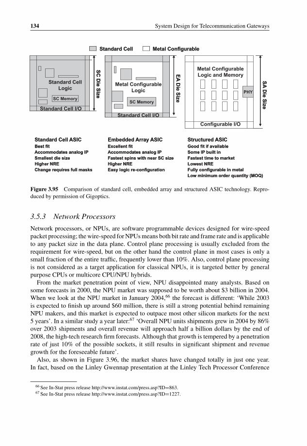
P1: OTA/XYZ P2: ABCc03 BLBK307-Bachmutsky September 2, 2010 13:12 Printer Name: Yet to Come
134 System Design for Telecommunication Gateways
SC Memory
Standard Cell Logic
Standard Cell I/O
SC
Die S
ize
SC Memory
Standard Cell I/O
Metal Configurable Logic
EA
Die S
ize
Metal ConfigurableStandard Cell
Configurable I/O
PHY
Metal Configurable Logic and Memory
SA
Die S
ize
Standard Cell ASICBest fitAccommodates analog IPSmallest die sizeHigher NREChange requires full masks
Embedded Array ASICExcellent fitAccommodates analog IPFastest spins with near SC sizeHigher NREEasy logic re-configuration
Structured ASICGood fit if availableSome IP built inFastest time to marketLowest NREFully configurable in metalLow minimum order quantity (MOQ)
SC Memory
Standard Cell Logic
Standard Cell I/O
SC
Die S
ize
SC Memory
Standard Cell I/O
Metal Configurable Logic
EA
Die S
ize
Metal ConfigurableStandard Cell
Configurable I/O
PHY
Metal Configurable Logic and Memory
SA
Die S
ize
Standard Cell ASICBest fitAccommodates analog IPSmallest die sizeHigher NREChange requires full masks
Embedded Array ASICExcellent fitAccommodates analog IPFastest spins with near SC sizeHigher NREEasy logic re-configuration
Structured ASICGood fit if availableSome IP built inFastest time to marketLowest NREFully configurable in metalLow minimum order quantity (MOQ)
Figure 3.95 Comparison of standard cell, embedded array and structured ASIC technology. Repro-duced by permission of Gigoptics.
3.5.3 Network Processors
Network processors, or NPUs, are software programmable devices designed for wire-speedpacket processing; the wire-speed for NPUs means both bit rate and frame rate and is applicableto any packet size in the data plane. Control plane processing is usually excluded from therequirement for wire-speed, but on the other hand the control plane in most cases is only asmall fraction of the entire traffic, frequently lower than 10%. Also, control plane processingis not considered as a target application for classical NPUs, it is targeted better by generalpurpose CPUs or multicore CPU/NPU hybrids.
From the market penetration point of view, NPU disappointed many analysts. Based onsome forecasts in 2000, the NPU market was supposed to be worth about $3 billion in 2004.When we look at the NPU market in January 2004,66 the forecast is different: ‘While 2003is expected to finish up around $60 million, there is still a strong potential behind remainingNPU makers, and this market is expected to outpace most other silicon markets for the next5 years’. In a similar study a year later:67 ‘Overall NPU units shipments grew in 2004 by 86%over 2003 shipments and overall revenue will approach half a billion dollars by the end of2008, the high-tech research firm forecasts. Although that growth is tempered by a penetrationrate of just 10% of the possible sockets, it still results in significant shipment and revenuegrowth for the foreseeable future’.
Also, as shown in Figure 3.96, the market shares have changed totally in just one year.In fact, based on the Linley Gwennap presentation at the Linley Tech Processor Conference
66 See In-Stat press release http://www.instat.com/press.asp?ID=863.67 See In-Stat press release http://www.instat.com/press.asp?ID=1227.

P1: OTA/XYZ P2: ABCc03 BLBK307-Bachmutsky September 2, 2010 13:12 Printer Name: Yet to Come
Hardware Technologies and Platforms 135
Network Processors Market Shares(1st half 2003)
IBM, 21.3%
Motorola,19.8%
AMCC, 17.5%
Agere, 8.5%
Other, 10.5% Intel,
22.2%
Source: In-Stat/MDR, 12/03
Overall NPU Revenue Market Shares for 1H04
Intel, 28.1%
AMCC, 24.1%
Agere, 10.5%
Freescale,7.6%
Ezchip, 3.00%
Hifn, 11.4%
Vitesse, 11.8%
Other, 0.6%
Bay Micro, 2.9%
Source: In-Stat, 1/05
Figure 3.96 NPU market shares in 2003 and 2004. Reproduced by permission of In-Stat.
2009, the actual NPU market revenue was $305 million in 2008, which fell far short fromthe projected $500 million. Linley again presented a different list of vendors’ for 2008, whichincluded only seven vendors, as shown in Figure 3.97.
Most NPUs include the following functionalities:
� Header and payload pattern matching, or classifier, so as to be able to classify differentprotocols, mostly for Layer 2 (MAC), Layer 3 (networking; for example, IPv4), and Layer4 (transport; for example, TCP or UDP). There are a number of processing tasks performedby NPUs: Layer 2 to 4 data plane processing (packet driven IPv4 and IPv6 forwarding,Ethernet and MPLS switching, etc.); Layer 4 to 7 data plane processing, which is contentdriven and frequently involves deep packet inspection (DPI) with pattern matching using,for instance, regular expression or application-level protocol parsing (in general, DPI can be
DEFUNCT (15): Brecis, Clearwater,Cognigine, Internet Machines, IPFlex,Lexra, Navarro, Paion, Raqia, SiliconAccess, Silverback, Teradiant,Terago, Trebia, Zettacom
EXITED NPU MARKET (10): AppliedMicro/AMCC, Clearspeed, Fujitsu, IBM,Mindspeed, MIPS, Motorola, STMicro,TranSwitch, Vitesse
CURRENT NPU VENDORS (7):Agere (now LSI), Bay Micro, EZchip,Intel/Netronome, Sandburst (nowBroadcom), Wintegra, Xelerated
NOT REALLY NPUs (4):Broadcom SiByte, Marvell Prestera,PMC-Sierra RM9000, Ubicom
Figure 3.97 NPU vendors in 2008. Reproduced by permission of Linley.

P1: OTA/XYZ P2: ABCc03 BLBK307-Bachmutsky September 2, 2010 13:12 Printer Name: Yet to Come
136 System Design for Telecommunication Gateways
a part of NPUs, the topic will be reviewed separately in Section 3.5.5); classification of thecontrol plane that programs the data plane, mainly database-driven or high level protocoltermination (in many implementations it is performed by additional control processors, withNPU functionality limited to control plane packet identification and sending it to the controlprocessor). A number of hardware acceleration blocks can be included in the NPU to speedup the control plane processing, such as cryptography, XML processing engine, databasesearch acceleration, and others. In some devices NPU can terminate Layer 4 (TCP/UDP)sessions with some level of hardware offload (full HW termination, checksum calculation,timers and buffer management, etc.)
� Search in different data structures (tables, lists, trees, etc.) in internal or external memorybased on the port information and fields extracted from the packet header and/or payload;multiple independent, chained (one lookup result triggers another lookup) or hierarchicallookups (the result of a previous lookup is used as one of inputs for the next one) might beneeded for the required functionality.
� Packet modification, which can be either an addition of fields (for example, another level ofencapsulation), or a modification of fields (including counter increment or decrement, suchas IP Time-To-Live), checksum calculation, and packet split/gather functionality (fragmen-tation and reassembly).
� Multiple packet programming engines for scalability and performance.� Optional specialized co-processors for well-defined algorithms.� Streaming and other high speed network interfaces; it can include switch fabric interface for
integration into the bladed architectures.� Control and management planes redirect traffic to the integrated or external general purpose
processor; there is no requirement to process these packets at wire-speed.� Queue and traffic management for proper QoS handling; different NPUs have different
approaches and scope of the QoS handling.� Some amount of internal instruction and data memory for performance optimization; inter-
faces to external memories, frequently of different types, for packet buffers, lookup tables,counters, etc.
Network processors have already established a well-deserved place in telecom designsas a high performance and low power solution for packet handling in routers, gateways,switches and other networking devices. NPUs have proved themselves as a preferred solutioncompared to the legacy general purpose CPUs that were not really designed for pure dataplane applications. For example, Xelerated has made a comparison with a 40 Gbps application(20 Gbps full duplex) implemented using Intel Pentium 4 as a representative of GPCPUs,Broadcom and Intel RISC-based NPUs, Xelerated X10q and ASIC (see Figure 3.98; the barsin the graph indicate the number of processor chips required to achieve equivalent performancelevels; the resulting power dissipation is noted at the top of each bar). This comparison is,of course, Xelerated-biased, it would be better to see a comparison with the more advancedCavium Networks OCTEON processors (see Section 3.5.6.2.3), however in any case theconclusion is clear: for some mid- and high-performance networking applications that requireonly data plane processing at Layers 2 to 4, NPUs can be an efficient tool for achieving theproduct goals.
Xelerated believes that the main reason for such a big difference as shown on Figure 3.98,and which is relevant for all NPUs, is the difference in the basic processor architecture:
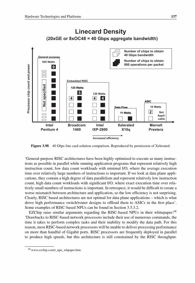
P1: OTA/XYZ P2: ABCc03 BLBK307-Bachmutsky September 2, 2010 13:12 Printer Name: Yet to Come
Hardware Technologies and Platforms 137
Increased efficiency
IntelPentium 4
Broadcom 1400
Intel IXP-2800
XeleratedX10q
Marvell Prestera
Linecard Density(20xGE or 8xOC48 = 40 Gbps aggregate bandwidth)
Number of chips to obtain 40 Gbps bandwidth
Number of chips to obtain 800 operations per packet
4 4
2
No
t sp
ecif
ied
9
54
General purpose
945 Watts
125 Watts
120 Watts
11 Watts
10 Watts
Embedded RISC
Data Flow
ASIC
Not Appli-cable
Pro
cess
or
chip
co
un
t an
d p
ow
er
4 4
2
No
t sp
ecif
ied
9
54
125 Watts
11 Watts
Data Flow
ASIC
Figure 3.98 40 Gbps line card solution comparison. Reproduced by permission of Xelerated.
‘General-purpose RISC architectures have been highly optimized to execute as many instruc-tions as possible in parallel while running application programs that represent relatively highinstruction count, low data count workloads with minimal I/O, where the average executiontime over relatively large numbers of instructions is important. If we look at data plane appli-cations, they contain a high degree of data parallelism and represent relatively low instructioncount, high data count workloads with significant I/O, where exact execution time over rela-tively small numbers of instructions is important. In retrospect, it would be difficult to create aworse mismatch between architecture and application, so the low efficiency is not surprising.Clearly, RISC based architectures are not optimal for data plane applications – which is whatdrove high performance switch/router designs to offload them to ASICs in the first place’.Some examples of RISC-based NPUs can be found in Section 3.5.3.2.
EZChip raise similar arguments regarding the RISC-based NPUs in their whitepaper:68
‘Drawbacks to RISC-based network processors include their use of numerous commands, thetime it takes to perform complex tasks and their inability to modify the data path. For thisreason, most RISC-based network processors will be unable to deliver processing performanceon more than handful of Gigabit ports. RISC processors are frequently deployed in parallelto produce high speeds, but this architecture is still constrained by the RISC throughput.
68 www.ezchip.com/t_npu_whpaper.htm.
P1: OTA/XYZ P2: ABCc03 BLBK307-Bachmutsky September 2, 2010 13:12 Printer Name: Yet to Come
138 System Design for Telecommunication Gateways
Moreover, there is a limit to the number of RISCs that can be incorporated without overlyincreasing system complexity and the size of the chip’.
A totally opposite view is provided by Bidyut Parruck and Greg Wolfson from AzandaNetwork Devices in their article ‘De-Evolution of the NPU’:69 ‘Proprietary NPU architecturesrequire too many resources and provide too little return. Creating an NPU requires the deve-lopment of proprietary processing cores, tools, development environments, and communicationand system software development, not to mention the technical and marketing evangelism thataccompanies these activities, none of which is sustainable in today’s fragmented communi-cations market’.
One problem with the comparison with CPUs is that the latest multicore processors (forexample, from Cavium Networks and NetLogic) are partially network processors and arenot considered in the analysis by Xelerated. On the other hand, EZChip does mention whatthey call ‘Augmented RISC-based Network Processors’: ‘Tailoring the RISC to networkingfunctions and adding hardware accelerators (boosters) is an alternative approach that speedsprocessing. Hardware accelerators can copy frames at wire speed to boost performance, butthe accelerator itself is neither flexible nor programmable. Again, this approach runs intothe limitations previously described for RISC-based network processors. Some chip vendorsemploy a combined RISC and ASIC architecture. With this approach, the RISC acts as thecore processor and certain tasks are offloaded to ASICs. Hard-wired ASICs provide the speed,but are severely restricted by their inherent inflexibility. ASICs are limited to the functionalityembedded in their silicon and cannot be updated to support new features’. It is not clearwhether Tilera, Cavium Networks and NetLogic processors are considered by EZChip to beaugmented RISC-based NPUs. If they are, some claims appear not to be applicable; if theyare not, there is a need to create another sub-group of NPUs.
We consider this latest generation of CPUs more as some kind of a mix between theNPU (with hardware classifiers and load balancers, hardware acceleration blocks for variousfunctions, including cryptography, timers, memory and buffer management and others) and thegeneral purpose CPU. The distinguishing feature of these processors is that the same engine(general purpose core with some optimizations for more efficient data plane processing) isused for both wire-speed data and high performance control plane processing. Therefore, wehave decided to deal with these in the discussion on multicore (see Section 3.5.6), knowingwell that these multicore processors can function successfully as NPUs with processing speedsfor some applications approaching 40 Gbps. As Linley Gwennap stated at the Linley TechProcessor Conference in 2009, ‘The right combination of accelerators and CPUs can matchthe power efficiency and performance of an NPU’.
3.5.3.1 Generic NPU Architecture
Generic NPU architecture (from the 2003 whitepaper by Roke Manor Research) is shownin Figure 3.99.70 To achieve the required performance numbers, the NPU normally includesmultiple packet processing engines. These engines can be arranged in many topologies, but
69 http://lw.pennnet.com/Articles/Article_Display.cfm?Article_ID=177770.70 Andrew Heppel, ‘An Introduction to Network Processors’, Roke Manor Research Ltd, 2003, http://www.roke.
co.uk/resources/white-papers/Network-Processors-Introduction.pdf.

P1: OTA/XYZ P2: ABCc03 BLBK307-Bachmutsky September 2, 2010 13:12 Printer Name: Yet to Come
Hardware Technologies and Platforms 139
Shared InternalMemory
Network Interface
Lookup Engine
Programmable Processing
Engine
Programmable Processing
Engine
Programmable Processing
Engine
Programmable Processing
Engine
SRAM Controller
Control Processor Interface
Switch Fabric
Interface
DRAM Controller
ExternalSRAM
Control Processor
Switch Fabric
ExternalDRAM
Net
wo
rk L
ine
Inte
rfac
es
Figure 3.99 Generic Network Processor Architecture. Reproduced by permission of Roke ManorResearch.
the most popular are the following: (a) a pool of parallel engines with some kind of loadbalancing to select the engine for the packet – every engine processes a packet fully anddifferent engines work on different packets in parallel; (b) a chain or pipeline where the entireprocessing algorithm is divided into smaller chunks with every one of them assigned to one ormore processing engines; (c) a hybrid of the previous two with a number of parallel pipelines.There is, however, one additional hybrid approach, where the hardware is implemented asa parallel architecture, but the software follows pipeline model. The scheme is possible ifthe hardware supports efficient message passing between processing engines, because suchcommunication can easily become a system bottleneck.
The hardware or software data flow pipelining approach has some disadvantages. One ofthem is that different processing stages frequently need different processing time, it is difficultto synchronize the time of these stages and in many cases some processing time is lost becausesome engines are loaded more than others. The designer needs to make sure that the processingengine has enough cycles to finish the stage. If for any reason the processing requirementshave changed later and some stages become overloaded, there is a need to redesign the entirepipeline, which is undesirable. To minimize the likelihood of such a situation arising, thedesigner usually ensures that every stage is loaded below a certain threshold value, causingsome processing capacity to be wasted and bringing inefficiency. In any case, in a pipelinemodel the slowest stage limits system throughput.
G. Lidington of Xelerated stated in his 2003 whitepaper ‘Programming A Data FlowProcessor’71 that pipeline topologies tend to trade off ease of programming in favour ofhardware efficiency, because pipelines expose the processing elements to the programmer,while parallel topologies tend to trade off hardware efficiency in favour of ease of programming.
71 http://www.xelerated.com/en/white-papers/.

P1: OTA/XYZ P2: ABCc03 BLBK307-Bachmutsky September 2, 2010 13:12 Printer Name: Yet to Come
140 System Design for Telecommunication Gateways
NPU programming is always a significant concern for every project. Xelerated claims, ofcourse, that all the advantages of their architecture ‘make it possible writing very efficientapplications using assembly language and some GUI-based application wizards’. There is noproblem in agreeing with the term ‘make it possible’, but based on experience of a numberof NPU projects, writing the NPU program in assembly is not straightforward and simplefor a ‘regular’ software engineer. Also, knowledge of assembly programming for XeleratedNPUs does not help much in programming. For example, with EZChip NPUs, programmers’expertise is very narrow, making it more difficult to move between projects or start a newproject using a different NPU. If FPGAs introduce high-level programming languages, thiswould also be expected from NPUs, On the other hand, the pure NPU concept lies in theirsuperefficiency and without it NPUs will quickly lose their competitive advantage.
As with many other technologies, network processors are going through a significant fea-ture consolidation phase which creates System-on-Chip (SoC). It began with the integrationof MAC functionality for various interface types and later added algorithmic searches andfast memory controllers to replace TCAMs and RLDRAMs or FCRAMs, integrated controlprocessor(s) to offload some aspects of the table programming and optimization. The latestdevelopment, based on EZChip’s announcement of NP-4’s intended benefits, is to includea function capable of displacing switch fabric interface chips, or more exactly to replaceexisting complex solutions with a simple Ethernet-based switch fabric with end-to-end con-gestion control. Not surprisingly, switch fabric vendors, such as Dune Networks, are fightingback with products that are targeted at the inclusion of full or partial NPU functionality in thefabric interface chip.
The future will reveal which solutions survive: only SoCs, or SoCs for lower end marketand separate chips for high-end (similar to CPU + GPU offerings), or anything else.
3.5.3.2 Commercial NPUs
The number of vendors offering ‘pure’ network processors is decreasing constantly. Thereasons for this trend include economic conditions, mergers, competition between NPUs andfrom ‘neighboring’ solutions (for instance, hybrid CPU/NPU and switch fabric), moving somevendors out of the market or at least out of the pure NPU market (Intel and IBM are goodexamples here), limited market size for very high-end solutions, etc. It looks like the trend willcontinue.
Also, there are a number of NPUs that clearly cannot be called commercial, because theyare not available for a broad market. One example of such an NPU is that developed byCisco Systems, the Quantum Flow Processor (QFP). We prefer to describe it here becausethe same principle can be used for creating another proprietary NPU if it becomes critical. Ofcourse, in such a situation every project will have to be ready to spend a lot of money on suchdevelopment: Cisco Systems claimed to have employed some 100 engineers on the project,filed more than forty patents and spent about $100 million on QFP, designing their ASIC andeven their own package so as to improve signal integrity.
Cisco Systems’ 1.3 billion-transistor QFP is built with forty customized 900 MHz to1.2 GHz 32-bit Tensilica cores (called Packet Processing Engine, or PPE) interconnectedby high performance cross bar switch. Each core has four hardware threads achieving up to160 parallel threads on a single chip (for comparison, Sun UltraSparc T2 runs up to sixty-fourthreads; see Section 3.5.6 for more information about hardware multithreading vs. multicore).

P1: OTA/XYZ P2: ABCc03 BLBK307-Bachmutsky September 2, 2010 13:12 Printer Name: Yet to Come
Hardware Technologies and Platforms 141
PPEPPE
PPEPPE
PPE
DRAM Interface
TCAM Interface
Internal Resources
CP
U
Inte
rfac
e
Packet Buffer + Queuing Memory
DRAMs TCAM
Resource Interconnect
On-ChipPacket Memory
Buffering, Queuing, Scheduler
Packets In
Packets Out
PPEPPE
PPEPPE
PPE
DRAM Interface
TCAM Interface
Internal Resources
CP
U
Inte
rfac
e
Packet Buffer + Queuing Memory
DRAMs TCAM
Resource Interconnect
On-ChipPacket Memory
Buffering, Queuing, Scheduler
Packets In
Packets Out
Figure 3.100 Cisco Quantum Flow Processor block diagram. Reproduced by Cisco.
The 16 KB L1 cache is shared across threads from the same PPE, and the dual 256 KB L2cache is shared across threads from all PPEs. The chip is programmed in C-language, hasno fixed-feature pipeline with full header and payload access and is built to accelerate verycomplex router or gateway control and data plane QoS-aware tasks, such as firewall, intrusiondetection and prevention, Virtual Private Networks (VPN) with IPsec tunnels, Deep PacketInspection (DPI) with parsing of XML and other protocols, Session Border Control (SBC)and much more. This is done through sophisticated tree lookups, hashing functions, efficientmemory access and complex algorithms for concurrent handling of large number of flows.
The QFP (see the block diagram in Figure 3.100) uses centralized shared memory architec-ture with a great deal of on- and off-chip memory instead of extensive TCAM usage, while stillproviding TCAM interface. Multiple threads hide the memory access latency. Cisco Systemsinitially uses four SPI 4.2 external ports with 10 Gbps throughput each, and there are plansto implement higher speed Interlaken links with 40 Gbps and higher throughput in futuregenerations.
Each core/PPE uses the running-to-completion paradigm for the complete packet processingof a particular packet. Each PPE thread is QoS-aware and can process packets for any new orexisting flows that are found in large per service databases available to each PPE. The PPEthread is not dedicated to specific flow processing or specific functions and can run throughany software implemented by the QFP. In general, each PPE tries to process completely thepacket in one pass; but for more complex tasks, such as those that include ingress shaping andmulticast handling, it has to use multiple passes. The QFP can collect detailed flow informationfor applications and services: duration, packet, and byte counts; packet fragments and copiesfor applications such as the Encapsulated Remote Switched Port Analyzer (ERSPAN) andFlexible NetFlow and Lawful Intercepts; detailed session setup and teardown logs for Cisco

P1: OTA/XYZ P2: ABCc03 BLBK307-Bachmutsky September 2, 2010 13:12 Printer Name: Yet to Come
142 System Design for Telecommunication Gateways
IOS Firewall and NAT; call quality for session-border-controller (SBC) applications; flexibleflow monitoring for NetFlow collection (the QFP can export huge amounts of flow cache datadirectly off the processor, further reducing CPU usage of control processors in the routingplatform); auditing for information concerning all active flows; and signal the control planewhen some policy function needs to be made aware of the end of life of a flow.
PPEs have access to internal acceleration engines for network address, prefix, range andhash lookups, Weighted Random Early Detection (WRED), and traffic policers.
The integrated traffic manager has the following functionality:
� 128 K queues with three bandwidth parameters for each queue: maximum, minimum andexcess; in addition, two priority queues can be enabled for each QoS policy applied.
� The number and makeup of layers inside the QoS policy are flexible. The traffic managercan implement almost any hierarchy under the control of software.
� The traffic manager can schedule multiple levels (no limit) of the hierarchy in one passthrough the chip. Further, queuing operations can be split across multiple passes throughthe chipset (for example, ingress shaping or queuing followed by egress queuing). SeparateQoS polices can be applied to physical interfaces and logical interfaces simultaneously andthen linked together into the same queuing hierarchy.
� The priority of a packet is preserved and propagated down through the processing hierarchy.� External resources such as cryptographic devices and route processors are scheduled appro-
priately making sure that they are never overwhelmed.
Integrated threat-control services (including firewall, Network-Based ApplicationRecognition (NBAR) with deep and stateful packet inspection, NetFlow technology to detectanomalies in the network, and source-based Remote-Triggered Black Hole Filtering (RTBH)to set the next hop of the victim’s IP address to the null interface, see Figure 3.101) areperformed in the QFP itself. The initial firewall session setup packets are processed by thehardware. In addition, the QFP performs high-speed firewall and NAT syslogging directly offthe forwarding plane, minimizing any degradation or load in the route processor.
S/RTBH
S/RTBH BGP Trigger
Target
DDoS
ISP A
ISP BQFP
QFP
Figure 3.101 Cisco source-based Remote-Triggered Black Hole Filtering in QFP. Reproduced byCisco.

P1: OTA/XYZ P2: ABCc03 BLBK307-Bachmutsky September 2, 2010 13:12 Printer Name: Yet to Come
Hardware Technologies and Platforms 143
JTAG and Test Interface
LA1 Interface
External Memory Interface (XMI)
Flow Database Memory Interface
Packet Database Memory Interface
FCN Interface
QAB
General Control Interface
General Purpose Input/Output (GPIO) Interface
4 x GE SPI-3Channel Service Memory Interface
Host CPU Interface
SP
I-4.
2
SP
I-4.
2
XSCHash
EngineCache
SPU
Program Memory
nPcore Farm
Queuing
Scheduling
Traffic Manager
Packet Transform Engine (PTE)
Channel Service Module (CSM)
TX
TX RX
RX
SP
I-3
4xG
E
PLLs
Policy Engine (PC-CAM)
ICP Memory
Programmable Statistics Engine
Figure 3.102 AppliedMicro nP7310 Block Diagram. Reproduced by permission of AppliedMicro.
There are few details about QFP high availability features, only that the software uses avirtualization layer that can allow for single chip failovers and in-service upgrade.
3.5.3.2.1 AppliedMicro nP7310The nP7310 (see Figure 3.102 for the block diagram) 10-Gbps half-duplex integrated networkprocessor from Applied Micro Circuits Corporation utilizes AppliedMicro’s nP5TM technologythat combines nPcore with traffic management supporting up to 128 K queues and enablesdevelopers to deliver fine-grained control of subscriber traffic, without impacting upon theability to perform complex protocol processing at wire speeds. nP7300 is similar to slightlydifferent interfaces: with the additional SPI-3 link replacing three Gigabit Ethernet ports.
Some of the highlights of nP7310 are:
� Three nPcores at 700 MHz optimized for network processing, each with twenty-four separatetasks and zero-cycle switching and branching; 64 KB instruction space, 16 K instructions.
� Flexible bandwidth allocation; for example, half-duplex OC-192, full-duplex OC-48, OC-12plus 12x OC-3, etc.
� Deep Channelization.– Allows fractional T3/E3 and T1/E1 logical channels.– Can receive interleaved chunks of jumbo packets, perform packet processing on each
chunk separately and reassemble a jumbo packet in the fabric.� Single-stage single-image programming model for simplified software development and
troubleshooting; in this model each cell or packet is processed from start to finish by a singletask in a single nPcore.
� High-speed RLDRAM-II memory interfaces for payload and context storage.

P1: OTA/XYZ P2: ABCc03 BLBK307-Bachmutsky September 2, 2010 13:12 Printer Name: Yet to Come
144 System Design for Telecommunication Gateways
– Payload and context memory: each has two banks of 36-bit RLDRAM II operating at upto 250 MHz (32 Gbps with ECC).
– Channel Service Memory: One bank of 36-bit QDR-II SRAM operating at 300 MHz.– Flow Database Memory: Two banks of 18-bit QDR-II SRAM operating at up to 250 MHz.
� CPU interfaces.– Dedicated PowerPC interface.– Gigabit Ethernet.
� Per-flow metering and statistics for millions of flows.� Packet admission control with dynamic queue limits.
– WRED, Early packet Discard (EPD), Trail Packet Discard (TPD) in hardware.– Any variations in software.
� Integrated hierarchical Traffic Manager.– Four logical levels: flow, pipe, subport and port.– Per-flow queuing and scheduling.
◦ 128 K ingress and egress flows: Strict Priority, Min, Weighted Round Robin (WRR);rate-shaping (Constant Bit Rate (CBR), Variable Bit Rate (VBR)); up to 64 K flowsmay participate in Flow Priority Queue grouping where four egress flows are scheduledwithin the group according to pre-assigned weight.
◦ 4 K pipes: Strict Priority, Min, Weight, Max, XON/XOFF.◦ 512 subports (logical port/channel): Min, Max, WRR, XON/XOFF.◦ 64 subport groups: Max bandwidth capping, XON/XOFF.
� Weighted Fair Queuing (WFQ) and Strict Priority scheduling algorithms.� Standards-Compliant Interfaces.
– Integrated four GE MACs (GMII).– One OIF SPI-3.– One OIF SPI-4.2 for fabric interface.
� External LA-1 lookaside Interface compatible with existing TCAMs.� Integrated co-processors.
– Policy engine for efficient packet classification.– Special purpose unit for per-flow single and dual leaky bucket and token bucket policing
on cells and frames.– Hashing unit to accelerate table lookups; programmable polynomial (for example, CRC
generation).– On-chip debugger.– Packet transform engine for egress packet modifications.– Programmable atomic statistics engine to handle large amount of flow counters.– Channel service module for store-and-forward functionality.
� nPsoftTM development environment.– Combines the nPcoreTM programming model with nPsoft services, advanced develop-
ment tools, reference application libraries, and both simulation and real hardware-baseddevelopment systems.
– Speeds the development, debugging, and delivery of Layer 2 – Layer 7 applications.
The 10 Gbps full duplex system diagram is shown in Figure 3.103; it consists of dual nP73x0network processors; one used for ingress processing, the other is for egress processing.

P1: OTA/XYZ P2: ABCc03 BLBK307-Bachmutsky September 2, 2010 13:12 Printer Name: Yet to Come
Hardware Technologies and Platforms 145
TM Payload Memory
LA-1Context Memory
CSM Memory
TM Flow Database
TM Payload Memory
LA-1Context Memory
CSM Memory
TM Flow Database
Host CPU
SERDES/ PHY
SERDES/ PHY
10x GE MAC
nP7300 Ingress
nP7300 Egress
SPI-4.2 RX
SPI-4.2 RX
SPI-4.2 TX
SPI-4.2 TX
SPI-3
1x GE
1x GE
10x GE MAC
nP7300 Ingress
nP7300 Egress
SPI-3
Figure 3.103 AppliedMicro nP73x0 10 Gbps Full Duplex System Diagram. Reproduced by permissionof AppliedMicro.
A key feature of the nP7310 architecture is the exception channel processing which providesflexibility in handling packets that require increased processing time. This exception channelhandles special packets through a secondary path, without affecting the deterministic line-rateperformance of the regular packets in the primary path. The addition of a special preprocessor,the Channel Service Module (CSM), offers a store-and-forward capability to the nP7310architecture. The CSM is able to buffer incoming traffic according to the level of channelizationof the line interfaces. A sizable CSM buffer absorbs large bursts in the incoming traffic withoutdata losses.
3.5.3.2.2 EZChip NPUsEZChip network processors are described in detail by Ran Giladi in his recent book [NPU-EZChip-Giladi].
NP-3 is the latest (as of the time of writing) 30 Gbps fourth generation network processorfrom EZChip with high capacity interfaces: 10 Gigabit Ethernet with integrated MACs, one10 Gigabit Ethernet XGMII port with integrated MAC that can operate in 20 Gbps modewith overclocking (can be used, for example, for two NP-3 chips connected back-to-back, seeFigure 3.104), and two SPI 4.2 interfaces. NP-3 is programmable to support practically anyprotocol parsing in any place in the packet.

P1: OTA/XYZ P2: ABCc03 BLBK307-Bachmutsky September 2, 2010 13:12 Printer Name: Yet to Come
146 System Design for Telecommunication Gateways
Figure 3.104 EZChip NP-3 for 10 GE ring application. Reproduced by permission of EZChip.
Some additional features include:
� Integrated ingress and egress Traffic Manager.– Frame size up to 16 KB.– Up to 1 GB of frame memory.– Per-flow queuing with four levels of hierarchy, WFQ and priority scheduling at each
hierarchy level.– Per-flow metering, marking and policing for millions of flows.– Configurable WRED profiles.– Shaping with single and dual leaky bucket controlling committed/peak rate/bursts (CIR,
CIB, PIR, PIB) with inter-frame gap emulation for more accurate rate control.� Integrated search engines.
– Flexible large lookup tables with millions of entries.– Programmable keys and associated information (result) per table.– Use of DRAM for table storage with up to 2 GB of available space, lower power dissipation
and cost compared to the RLDRAM or TCAM based solution.� Stateful classification and processing.
– Access to all seven layers for packet classification and modification.– On-chip simultaneous state updates and learning of millions of sessions per second.
� Programming.– Special microcode is used with single-image programming model.– In-service software updates.– Automatic packet ordering.
� OAM offload.– Keep-alive frame generation.– Keep-alive watchdog timers.
� Statistics and counters.– Up to 16M 36-bit counters (using external SRAM).– Auto implementation of token bucket per flow (srTCM, trTCM or MEF5).
EZChip NPUs are built using pipelined Task Optimized Processors (TOPs), as shown inFigure 3.105. Pipeline design enables parallel processing of multiple packets simultaneously.In addition to a pipeline-based parallelization, each TOP is built using multi-instanced engines

P1: OTA/XYZ P2: ABCc03 BLBK307-Bachmutsky September 2, 2010 13:12 Printer Name: Yet to Come
Hardware Technologies and Platforms 147
Figure 3.105 EZChip NPU architecture. Reproduced by permission of EZChip.
assigned dynamically by a hardware load balancing mechanism on a packet-per-packet basis.The assigned engine finishes its task and passes the results to the next TOP stage. There arefour types of TOPs:
� Microprogrammable TOPparse is responsible for classification of the incoming packets,extracting the required fields at all layers from Layer 2 to Layer 7 (addresses, ports, protocolIDs, tags, application-specific information, etc.) at any place in the packet and passing thesefields on to the next step.
� Highly configurable TOPsearch handles most lookup operations (some other TOPs havelimited search capabilities) for routing, classification, policy enforcement and other tasksusing three main data structures: direct access tables for quick and simple searches, hash-based tables with fixed-width keys and trees with variable-width keys including optionalwild card (do not care) capabilities. TOPsearch also implements complex compound lookupsusing different structures and structure types. EZChip NPUs integrate efficient proprietarysearch algorithms allowing for usage of regular DDR memories as opposed to more expensiveRLDRAM and TCAM technologies. However, TCAM can still be used if significant amountof ACL rules is required. As shown in Figure 3.105, EZChip architecture supports twoseparate dedicated search stages: TOPsearch-I before the TOPresolve stage and optionalTOPsearch-II after it. TOPsearch-I has an access to internal and external search memory,integrated ‘low learn’ Layer 2 MAC and Layer 3 IP address automatic learning and agingmachines capable of learning and updating millions of addresses/sessions/flows per secondand a TOPresolve driven ‘high learn’ using special add/update/delete messages that can begenerated as a part of the decision-making process. The learning process can be triggered bymessages from the host processor. TOPsearch-II is much simpler than TOPsearch-I. It hasaccess only to internal search memory and is able to perform lookups only in direct accessand hash tables.
� Microprogrammable TOPresolve makes major decisions based on classification and searchresults, such as packet drop or forward to a particular physical or logical port for both unicastand multicast packets. It performs counting for statistics collection. As described above, itcan trigger a learning process in TOPsearch-I.

P1: OTA/XYZ P2: ABCc03 BLBK307-Bachmutsky September 2, 2010 13:12 Printer Name: Yet to Come
148 System Design for Telecommunication Gateways
� Microprogrammable TOPmodify prepares the outgoing packet by cutting, modifying oradding/inserting the required field(s) from/to the packet at any location and sends the packetto its destination port and queue. It can add, modify or remove the VLAN or MPLS labels,add or remove IP encapsulation for Layer 3 tunneling applications, etc. TOPresolve canprovide references to routines that have to be run by TOPmodify.
There is an additional and critical functionality applied at the very beginning and after packetmodification – ingress and egress traffic management providing hierarchical per-flow (and/oraggregated flows) traffic metering, policing, WRED congestion avoidance, priority-based andWeighted Fair Queuing (WFQ) scheduling and dual leaky bucket traffic shaping.
Over the entire processing pipeline the packet is maintained in the internal frame buffer,which is filled and released by the hardware. TOPs access the frame using frame descriptorsand shared frame buffer, there is no need to copy a packet between pipeline stages. Also,passing parameters between TOPs is highly optimized using special dedicated register files.
EZChip offers a scaled down version of NP-3 called NPA which comes in three models:NPA-1 with 8 Gigabit Ethernet ports, NPA-2 with 16 Gigabit Ethernet ports, and NPA-3 thatcan be configured with either 8 SGMII Gigabit Ethernet ports and two 10 Gigabit Ethernetports, or 12 SGMII Gigabit Ethernet ports and one 10 Gigabit Ethernet port, or four 10 GigabitEthernet ports. NPA is targeted at access market, wireless backhaul and high-speed 3G/4Gbase station aggregation capable of processing up to 10 Gbps of Layer 2 switching, QinQ,PBT, T-MPLS, VPLS, MPLS and IPv4/IPv6 forwarding.
NPA integrates on-chip traffic manager, Fabric Interface Controller, TCAM for ACLlookups, IEEE 802.1ag and IEEE 802.3ah OAM protocol processing offload with per-flowqueuing (up to 16 K flows are supported) and four-level hierarchical scheduling, IEEE 1588v2clock sync processing offload and many other blocks, all with 6 W–10 W of typical powerdissipation.
Based on the EZChip press release of May 2008 and the sampling news of January 2010,the forthcoming NP-4 chip will support some extension to video traffic transport optimization.The EZChip website provides the following information about the NP-4:
‘The NP-4 . . . will provide groundbreaking levels of integration and functionality for equipmentvendors building the next generation of Carrier Ethernet Switches and Routers (CESR). It providesa total of 100-Gigabit throughput and features a 100-Gigabit port, ten 10-Gigabit ports and twenty-four 1-Gigabit Ethernet ports.
NP-4 features integrated hierarchical traffic management, OAM processing offload and enablesdirect connection from the line card to Ethernet-based switching fabrics. This is achieved througha unique integration of the functionality typically provided by a separate fabric interface chip andallows system vendors to utilize low-cost Ethernet switches as their fabric solution and eliminatethe fabric interface chip from their line cards.’
The highlights of NP-4 include:
� 100 Gbps throughput for building 40–400 Gigabit line-cards and pizza boxes.� Integrated traffic management providing granular bandwidth control.� Enhanced support for video streams and IPTV.
P1: OTA/XYZ P2: ABCc03 BLBK307-Bachmutsky September 2, 2010 13:12 Printer Name: Yet to Come
Hardware Technologies and Platforms 149
� On-chip control CPU for host CPU offload.� Power management for minimizing line card and system power dissipation.� Operations, Administration and Management (OAM) processing offload.� Synchronous Ethernet and IEEE1588v2 offload for Circuit Emulation Services.� IP reassembly for advanced packet processing offload.� Integrated serial ports with support for 1, 10, 40 and 100 Gigabit Ethernet.� On-chip Fabric Interface Controller for interfacing to Ethernet-based as well as proprietary
switch-fabric solutions.� Utilizing DDR3 DRAM memory chips for minimizing power and cost.� Software compatible with EZchip’s NP-2, NP-3 and NPA network processors.
There is also a ‘light’ version of NP-4, the NP-4 L, that provides 50 Gbps throughput to fillthe gap between NP-3 and NP-4.
3.5.3.2.3 LSI Advanced PayloadPlus NPUsLSI Advanced PayloadPlus (APP) network processors are SoCs with speeds from 300 Mbpsto 6 Gbps. The APP heterogeneous NPUs contain programmable engines including a patentedclassification engine and compute engines to handle tasks such as buffer management, trafficshaping, data modifications and policing.
One series of these network processors, the LSI APP300 family, provides up to 2 Gbps ofprotocol classification as well as policing/metering and statistics functions, all with 3–5 Wpower dissipation in typical configurations. For ATM applications, it includes support for ATMswitching, AAL2 CPS processing and AAL5 SAR with up to 4 K VCI/VPI, 4 K simultaneousreassemblies and per-VC policing, traffic management and statistics gathering.
Some of the other ready-to-run features are:
� Integrated ARM9-based control processor, classification engine, traffic management forwire-speed packet and ATM scheduling (WRR, DWRR, SDWRR, WFQ, strict priority;support for CBR, VBR-rt, VBR-nrt, UBR).
� High-level programming language to program processing of ATM efficiently and a widerange of packet-based protocols: Ethernet, POS, IGMP Snooping, IPv4, IPv6, DiffServ,NAT/NAPT, IP multicast, L2TP, PPTP, PPPoE/PPPoA, etc.
� Ethernet support: Layer 2 bridging, IEEE 802.1P for Ethernet based CoS, IEEE 802.1QVLAN and stacked VLAN (Q-in-Q) support, IEEE 802.3ad link aggregation, IEEE 802.3ahMAC-in-MAC, etc.
� OAM (I.610): AIS/RDI alarm indication signals/ remote defect indication, continuity check,loopback, performance monitoring, and Ethernet OAM IEEE 802.1ah.
The LSI APP2200 and APP3300 families scale up to 3.5 Gbps with approximately 5 Wpower in typical configurations; they enhance the NPU with integrated dual-core ARM11 CPUfor control and management planes processing (see Figure 3.106).
APP2200 and APP3300 add another level of integration by incorporating security andpublic key accelerator blocks with true and pseudo random number generators to handle IPsecprotocol with up to 1.5 Gbps of DES, 3DES or AES 128/192/256 cryptography, and HMACSHA-1/224/256, HMAC, MD5, AES-XCBC-MAC, AES-CM and AES-GCM 128/192/256authentication algorithms.

P1: OTA/XYZ P2: ABCc03 BLBK307-Bachmutsky September 2, 2010 13:12 Printer Name: Yet to Come
150 System Design for Telecommunication Gateways
Figure 3.106 LSI APP3300 Block Diagram with dual-core ARM11 and Security Engine. Reproducedby permission of LSI.
3.5.3.2.4 XeleratedXelerated network processors are based on a number of architectural principles:
� A simple data flow processor with a small processing core, low complexity and a single setof registers.
� A VLIW-like instruction which specifies up to four instructions and allows their executionin parallel. Xelerated claims that this is the optimal number that matches the requirements ofdata plane applications. It also allows for high instruction bandwidth and eliminates stalls.There is no need for branch delay slots and complex branch prediction logic, because branchinstruction is executed at a single stage of the pipeline and the next instruction pointer issimply passed to the next processor together with a data.
� Acceleration blocks are implemented as coprocessors as opposed to the extension of theinstruction set, all targeted at minimizing the processor size.
� All processors are connected by a simple linear pipeline to eliminate the need for a com-plex, power-inefficient bus or crossbar interconnect between processors. There is no needfor memory connectivity in a large data store with significant additional pin count. In
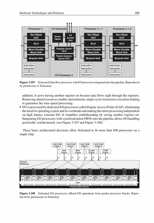
P1: OTA/XYZ P2: ABCc03 BLBK307-Bachmutsky September 2, 2010 13:12 Printer Name: Yet to Come
Hardware Technologies and Platforms 151
Set Offset Unit
ALU
Move Double Word Unit
Branch Unit
Driver Tables
I/OAccess
Unit
Register Synch FIFO
Packet memory Synch FIFO
I/O ChannelsProcessor n
I/O Processor n
Instruction
Instruction
Instruction
Set Offset Unit
ALU
Move Double Word Unit
Branch Unit
Processor n + 1
Instruction
Instruction
Instruction
Set Offset Unit
ALU
Move Double Word Unit
Branch Unit
Processor n + 2
Instruction
Instruction
Instruction
Set Offset Unit
ALU
Move Double Word Unit
Branch Unit
Driver Tables
I/OAccess
Unit
Register Synch FIFO
Packet memory Synch FIFO
I/O ChannelsProcessor n
I/O Processor n
Instruction
Instruction
Instruction
Instruction
Instruction
Instruction
Set Offset Unit
ALU
Move Double Word Unit
Branch Unit
Processor n + 1
Instruction
Instruction
Instruction
Instruction
Instruction
Instruction
Set Offset Unit
ALU
Move Double Word Unit
Branch Unit
Processor n + 2
Instruction
Instruction
Instruction
Instruction
Instruction
Instruction
Figure 3.107 Xelerated Data flow processor with I/O processor integrated into the pipeline. Reproducedby permission of Xelerated.
addition, it saves having another register set because data flows right through the registers.Removing shared resources enables deterministic single-cycle instruction execution helpingto guarantee the wire-speed processing.
� I/O is processed by dedicated I/O processors called Engine Access Points (EAP), eliminatingthe need for operating system and its overheads and making the entire processing independenton high latency external I/O. It simplifies multithreading by saving another register set.Integrating I/O processors with synchronization FIFOs into the pipeline allows I/O handlingpractically synchronously (see Figure 3.107 and Figure 3.108).
These basic architectural decisions allow Xelerated to fit more than 800 processors on asingle chip.
Channel Multiplexer
Programmable Pipeline
PISC™Block#0
EAP
#0
PISC™Block#1
EAP
#1
PISC™Block#2
EAP
#2
PISC™Block#3
EAP
#3
PISC™Block#4
EAP
#4
PISC™Block#5
EAP
#5
PISC™Block#6
EAP
#6
PISC™Block#7
EAP
#7
PISC™Block#8
EAP
#8
PISC™Block#9
EAP
#9
EAP
#10
Look AsideEngine 0
Look AsideEngine 1
Look AsideEngine 2
Look AsideEngine 3
HashEngine
MeterEngine
CounterEngine
TCAMEngine
55 221 481
Data
Figure 3.108 Xelerated I/O processors offload I/O operations from packet processor blocks. Repro-duced by permission of Xelerated.

P1: OTA/XYZ P2: ABCc03 BLBK307-Bachmutsky September 2, 2010 13:12 Printer Name: Yet to Come
152 System Design for Telecommunication Gateways
SNMP OSPF 802.1d/q …
Network Control Applications
Control Plane (Host Processor)
IPv4 API IPv6 API 802.1d/q API …
Integration Support Libraries
Middleware
Tables Tables TablesClassify
(I/O Processor)Classify
(I/O Processor)Classify
(I/O Processor)
Processor Processor Processor
Action (Virtual Processor)
Action (Virtual Processor)
Action (Virtual Processor)
Forwarding Plane (NPU)
Shared Data Structures
Update
Request
Response
SNMP OSPF 802.1d/q …
Network Control Applications
Control Plane (Host Processor)
IPv4 API IPv6 API 802.1d/q API …
Integration Support Libraries
Middleware
TablesTables TablesTables TablesTablesClassify
(I/O Processor)Classify
(I/O Processor)Classify
(I/O Processor)
ProcessorProcessor ProcessorProcessor ProcessorProcessor
Action (Virtual Processor)
Action (Virtual Processor)
Action (Virtual Processor)
Forwarding Plane (NPU)
Shared Data Structures
Update
Request
Response
Figure 3.109 Xelerated NPU programming model. Reproduced by permission of Xelerated.
Xelerated designers tried to ease as much as possible the misery of NPU programming(however, do not expect NPU programming to be simple). In their model, the system archi-tect’s job is to specify the data structures and create ‘virtual processors’ that include one ormore physical processing blocks – enough to perform the required action with wire-speed (seeFigure 3.109). Instead of cycle budget estimation, it is enough to estimate instruction budgets.The programmer sees only a single-threaded processor with ingress and egress data structures,which is programmed using the ‘Multi-Stage Classify/Action Programming Model’. Classi-fication includes both table search and update; action includes packet parsing, extraction ofsearch fields and processing of search results.
Xelerated introduced two series of NPUs. The first, XeleratorR©
, includes X10 and X11.X10 is a pure NPU without integration of MACs, TM or Switch Fabric Interface (SFI). X11(announced in October 2003) added integrated Gigabit Ethernet and 10 Gigabit Ethernet MACswith HW MAC learning and aging and performance/scalability enhancements.
The X11 family of four NPUs is designed for packet size independent wire-speed up to fullduplex 20 Gbps processing in Metro Transport, Carrier Ethernet Switch Routers and ServiceRouters; NPUs run at 200 MHz to 240 MHz core frequency and have one or two SPI-4.2interfaces, one or two 10 Gigabit Ethernet interfaces, and twelve to twenty-four Gigabit/FastEthernet interfaces. The architecture is derived from the data flow processing concept and isshown in Figure 3.110.
There are a few important blocks to mention: Multicast Copier which is responsible forpacket replication; Management Injector which is responsible for creating OAM packets;and TCAM engine which eliminates the need for external TCAMs in the case of smallerenterprise applications.
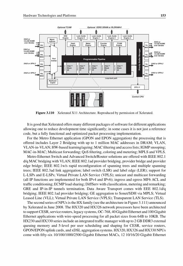
P1: OTA/XYZ P2: ABCc03 BLBK307-Bachmutsky September 2, 2010 13:12 Printer Name: Yet to Come
Hardware Technologies and Platforms 153
XAUI or SPI4.2
Control CPU
Optional TCAM
Programmable Pipeline
TX,MAC
NSEEngine
Look AsideEngine 0
Look AsideEngine 1
HashEngine
MeterEngine
CounterEngine
TCAMEngine
Look AsideEngine 2
Look AsideEngine 3
Optional DDR2 SRAM or RLDRAM-II
Loop-back path
MulticastCopier
TX,MAC
EAP
PISC™Block#0
EAP
PISC™Block#1
EAP
PISC™Block#2
EAP
PISC™Block#3
EAP
PISC™Block#4
Pro
cess
or
0
Pro
cess
or
1
Pro
cess
or
2
Pro
cess
or
31
XAUI or SPI4.2
TX,MAC
TX,MAC
Pri
ori
ty B
uff
er M
anag
er
XAUI or SPI4.2
XAUI or SPI4.2
XAUI or 12×GE/SGMII over Serdes
PortArbiter
RX,MAC
RX,MAC
RX,MAC
RX,MAC
XAUI or 12×GE/SGMII over Serdes
XAUI or 12×GE/SGMII over Serdes
XAUI or 12×GE/SGMII over Serdes
CPU i/f
Mgmt.Injector
Figure 3.110 Xelerated X11 Architecture. Reproduced by permission of Xelerated.
It is good that Xelerated offers many different packages of software for different applicationsallowing one to reduce development time significantly; in some cases it is not just a referencecode, but a fully functional and optimized packet processing implementation.
For the Metro Ethernet application (GPON and EPON aggregation) the processing that isoffered includes Layer 2 Bridging with up to 1 million MAC addresses in DRAM; VLAN,VLAN-in-VLAN; HW-based learning/ageing; MAC filtering and access lists; IGMP snooping;MAC-in-MAC; Multicast forwarding; QoS filtering, coloring and metering; MPLS and VPLS.
Metro Ethernet Switch and Advanced Switch/Router solutions are offered with IEEE 802.1d/q MAC bridging with VLAN; IEEE 802.1ad provider bridging, provider bridge and provideredge bridge; IEEE 802.1w/s rapid reconfiguration of spanning trees and multiple spanningtrees; IEEE 802.3ad link aggregation; label switch (LSR) and label edge (LER); support forL-LSPs and E-LSPs; Virtual Private LAN Service (VPLS); unicast and multicast forwarding(all IP functions are implemented for both IPv4 and IPv6); ingress and egress MF6 ACL andtraffic conditioning; ECMP load sharing; DiffServ with classification, metering and remarking;GRE and IP-in-IP tunnels termination. Data Aware Transport comes with EEE 802.1d/qbridging; IEEE 802.1ad provider bridging; GE aggregation to Sonet/SDH via MPLS; VirtualLeased Line (VLL); Virtual Private LAN Service (VPLS); Transparent LAN Service (TLS).
The second series of NPUs is the HX family (see the architecture in Figure 3.111) announcedby Xelerated in June 2008. The HX320 and HX326 network processors have been architectedto support CESR, service routers, legacy systems, OC-768, 40 Gigabit Ethernet and 100 GigabitEthernet applications with wire-speed processing for all packet sizes from 64B to 10KB. TheHX230 and HX330 series include an integrated traffic manager with up to 2 GB DDR3 externalqueuing memory and 5-level per user scheduling and shaping for CESR, service routers,GPON/EPON uplink cards, and xDSL aggregation systems. HX320, HX326 and HX330 NPUscome with fifty-six 10/100/1000/2500 Gigabit Ethernet MACs, 12 10/16/20 Gigabit Ethernet
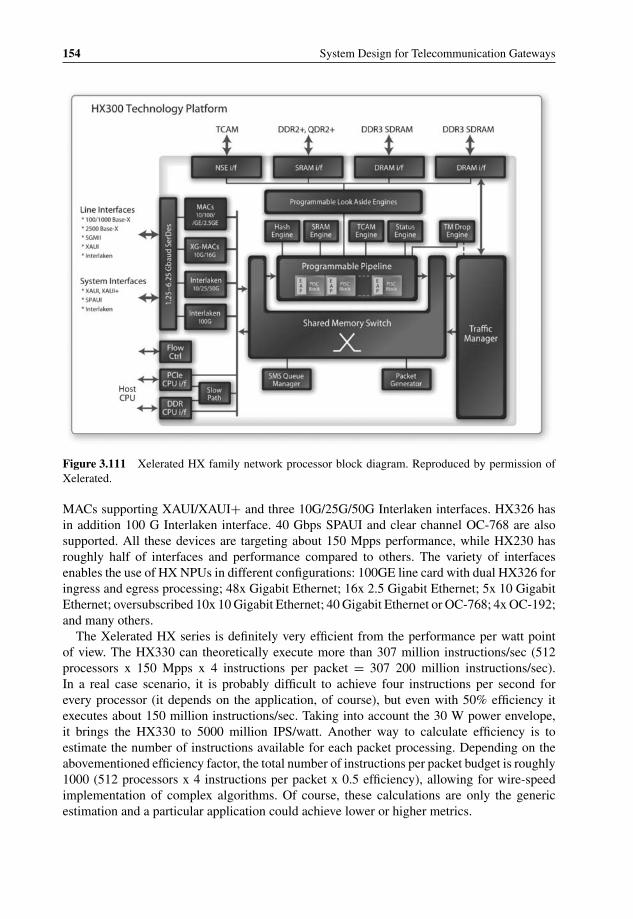
P1: OTA/XYZ P2: ABCc03 BLBK307-Bachmutsky September 2, 2010 13:12 Printer Name: Yet to Come
154 System Design for Telecommunication Gateways
Figure 3.111 Xelerated HX family network processor block diagram. Reproduced by permission ofXelerated.
MACs supporting XAUI/XAUI+ and three 10G/25G/50G Interlaken interfaces. HX326 hasin addition 100 G Interlaken interface. 40 Gbps SPAUI and clear channel OC-768 are alsosupported. All these devices are targeting about 150 Mpps performance, while HX230 hasroughly half of interfaces and performance compared to others. The variety of interfacesenables the use of HX NPUs in different configurations: 100GE line card with dual HX326 foringress and egress processing; 48x Gigabit Ethernet; 16x 2.5 Gigabit Ethernet; 5x 10 GigabitEthernet; oversubscribed 10x 10 Gigabit Ethernet; 40 Gigabit Ethernet or OC-768; 4x OC-192;and many others.
The Xelerated HX series is definitely very efficient from the performance per watt pointof view. The HX330 can theoretically execute more than 307 million instructions/sec (512processors x 150 Mpps x 4 instructions per packet = 307 200 million instructions/sec).In a real case scenario, it is probably difficult to achieve four instructions per second forevery processor (it depends on the application, of course), but even with 50% efficiency itexecutes about 150 million instructions/sec. Taking into account the 30 W power envelope,it brings the HX330 to 5000 million IPS/watt. Another way to calculate efficiency is toestimate the number of instructions available for each packet processing. Depending on theabovementioned efficiency factor, the total number of instructions per packet budget is roughly1000 (512 processors x 4 instructions per packet x 0.5 efficiency), allowing for wire-speedimplementation of complex algorithms. Of course, these calculations are only the genericestimation and a particular application could achieve lower or higher metrics.

P1: OTA/XYZ P2: ABCc03 BLBK307-Bachmutsky September 2, 2010 13:12 Printer Name: Yet to Come
Hardware Technologies and Platforms 155
2 CPU cores availableNot supported by IXB2800KAS boardsControl plane function
6 CPU cores (50%)100%Utilization
1,260 Mbps1,260 MbpsSupported Throughput Incoming IuCS/PS traffic
35Total Blades
11Spare
2 (6 of 8 CPU cores active)4Number of Blades: Active
Processor 5300 ServerXeon®Quad-Core Intel®IXB2800KAS (RNL-d board)Blades
Architecture ImplementationIntel®Network Processor Implementation
RNC Data Plane
2 CPU cores availableNot supported by IXB2800KAS boardsControl plane function
6 CPU cores (50%)100%Utilization
1,260 Mbps1,260 MbpsSupported Throughput Incoming IuCS/PS traffic
35Total Blades
11Spare
2 (6 of 8 CPU cores active)4Number of Blades: Active
Processor 5300 ServerXeon®Quad-Core Intel®IXB2800KAS (RNL-d board)Blades
Architecture ImplementationIntel®Network Processor Implementation
Figure 3.112 Comparison between Xeon multicore and IXP2800 network processor. Reproduced byIntel.
Xelerated NPUs are supported by the SDK, which includes a clock cycle accurate simulatorand a graphical IDE with code editor and an automated test case framework with code coverageanalysis tools.
3.5.3.2.5 NetronomeWhile the IXP28xx series of Intel NPUs is still called Intel NPUs, the entire NPU businesswas licensed by Intel to a relatively small company Netronome72 to continue the supportand development of the NPUs. However, existing devices will be manufactured by Inteluntil 2012. On the other hand, it is unlikely that new designs will be based on more thantwo-year-old IXP28xx technology, which means that it makes sense to review here only theNetronome solution called the Network Flow Processor (NFP) remembering that it is sourcecode backwards compatible to the original IXP28xx NPU. It is important to clarify that Intelcompetes directly with their previous IXP28xx technology by providing blades based on Xeonprocessors and whitepapers stating that multicore technology achieves better performancethan network processors (see Figure 3.112 taken from the Intel whitepaper ‘Packet Processingwith Intel R© Multi-Core Processors: General-Purpose Processor Exceeds Network ProcessorPerformance’73). Of course, the comparison is biased toward Intel CPUs, taking into accountonly the previous IXP28xx generation, which is very old from the point of view of thetechnology roadmap, where a few years equals an eternity. Also, the comparison does notconsider power, space and other design characteristics.
Netronome NFP32xx packet processing is carried out by forty octal-threaded programmablecores (with a total number of 320 threads; microengines provide a 16 Kwords shared instructionstore each for run-to-completion or pool-of-threads programming model) running at a corefrequency of up to 1.4 GHz with a power consumption of less than 35 W. Its interfaces includeeight PCIe v2.0 lanes, dual 25 Gbps Interlaken, SPI-4.2, dual 10 Gbps XAUI and LA-1interface for TCAM connectivity. The NFP32xx integrates security offload processors for upto 10 Gbps bulk encryption/decryption throughput (DES, 3DES, AES, SHA-1 and SHA-2 aresupported), PKI hardware to accelerate modular exponentiation, 48-/64-/128-bit hash supportfor security, regular expression and deduplication applications, as well as dedicated hardwarefor true random number generation. Hardware acceleration is also implemented for a work
72 http://www.netronome.com/.73 http://www.download.intel.com/technology/advanced_comm/QuickAssist_319889–001US.pdf.
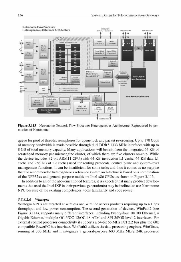
P1: OTA/XYZ P2: ABCc03 BLBK307-Bachmutsky September 2, 2010 13:12 Printer Name: Yet to Come
156 System Design for Telecommunication Gateways
Figure 3.113 Netronome Network Flow Processor Heterogeneous Architecture. Reproduced by per-mission of Netronome.
queue for pool of threads, semaphores for queue lock and packet re-ordering. Up to 170 Gbpsof memory bandwidth is made possible through dual DDR3 1333 MHz interfaces with up to8 GB of total memory capacity. Many applications will benefit from the integrated 64 KB ofscratchpad memory per microengine cluster, of which there are five clusters on-chip. Whilethe device includes 32-bit ARM11 CPU (with 64 KB instruction L1 cache, 64 KB data L1cache and 256 KB of L2 cache) used for routing protocols, control plane and system-levelmanagement functions, it can be insufficient for some tasks and thus it comes as no surprisethat the recommended heterogeneous reference system architecture is based on a combinationof the NFP32xx and general-purpose multicore Intel x86 CPUs, as shown in Figure 3.113.
In addition to all of the abovementioned features, it is expected that many product develop-ments that used the Intel IXP in their previous generation(s) may be inclined to use NetronomeNPU because of the existing competences, tools familiarity and code re-use.
3.5.3.2.6 WintegraWintegra NPUs are targeted at wireless and wireline access products requiring up to 4 Gbpsthroughput and low power consumption. The second generation of devices, WinPath2 (seeFigure 3.114), supports many different interfaces, including twenty-four 10/100 Ethernet, 4Gigabit Ethernet, multiple OC-3/OC-12/OC-48 ATM and SPI-3/POS level 2 interfaces. Forexternal control processor connectivity it supports a 64-bit 66 MHz PCI 2.2 bus plus the 60xcompatible PowerPC bus interface. WinPath2 utilizes six data processing engines, WinGines,running at 350 MHz and it integrates a general-purpose 600 MHz MIPS 24K processor

P1: OTA/XYZ P2: ABCc03 BLBK307-Bachmutsky September 2, 2010 13:12 Printer Name: Yet to Come
Hardware Technologies and Platforms 157
CPU I/F 60x or
PCI
SRAM/ DDR I/F
General System
Functions
MIPS 24K
DDR I/F
SRAM/ DDR I/F
WSE
16 SERIAL
WinNet
WinNet
UTOPIA 2/3 SPI3
EMPHY2
UTOPIA 2/3 SPI3
EMPHY2
FABRIC
WinComm2(Interworking)
FABRI C
FIFO Bus
FIFO Bus
Parameter BusPacket Bus
Optional InterfaceHost Bus
DATA
PATH
CONTROL
PATH
CPU I/F 60x or
PCI
SRAM/ DDR I/F
General System
Functions
MIPS 24K
DDR I/F
SRAM/ DDR I/F
WSE
16 SERIAL
WinNet
WinNet
UTOPIA 2/3 SPI3
EMPHY2
UTOPIA 2/3 SPI3
EMPHY2
FABRIC
WinComm2(Interworking)
FABRI C
FIFO Bus
FIFO Bus
Parameter BusPacket Bus
Optional InterfaceHost Bus
DATA
PATH
CONTROL
PATH
Figure 3.114 Wintegra WinPath2 Block Diagram. Reproduced by permission of Wintegra.
(32-bit address, 64-bit data path, short 8-stage pipeline) for control plane processing; powerconsumption is 6 W. It provides hardware accelerators, such as an integrated security engine forup to 1 Gbps of encryption/decryption and authentication (AES, DES, 3DES, Kasumi, SHA-1and MD5), hierarchical shaping (by cells, packet or byte count; shaping capabilities for WRR,fixed priority, min/max rate limit) with five levels of shaping through mix of hardware andsoftware, deep packet classification, intrusion detection, content searching, programmableCRC engines and more. Packet forwarding, protocol processing, and security tasks can beexecuted on each data portion on the fly and simultaneously. WinPath2 has three independentDDR1/DDR2 memory interfaces (packet, parameter and application), all running at 200 MHz.
One of the advantages of Wintegra NPUs is that they come with a good set of royalty-freeproduction-level implementations of standard protocols, including:
� Traffic management for ATM: TM4.1 UBR, CBR, GFR, VBR; hierarchical shaping (up tofive levels); policing with single/dual leaky bucket; congestion control (EPD/PPD); per VCqueuing.
� Traffic management for packet interfaces: hierarchical shaping, WFQ, policingwith single/dual leaky bucket, congestion control (WRED/TD), per flow queuing.
� QoS: multiple priority levels on all interfaces, multiple flows per VC, strict or WRR priorities,up to 64 K queues, buffer management, DiffServ, 3-colour marking, packet classification(Layer 2/Layer 3/Layer 4), unanchored string search anywhere in the packet, intrusiondetection, multi-channel backpressure over packet backplane interfaces (POS and Ethernet),statistics collection and reporting.

P1: OTA/XYZ P2: ABCc03 BLBK307-Bachmutsky September 2, 2010 13:12 Printer Name: Yet to Come
158 System Design for Telecommunication Gateways
� Aggregation: Inverse Multiplexing for ATM (IMA), multi-link PPP, multi-class PPP, PPPmux, multi-link Frame Relay, ATM G.Bond (G.998.1), Ethernet G.Bond (G.998.2), Ethernetlink aggregation (IEEE 802.3ad).
� Encapsulation: RFC1483/2684/1577, PPPoA, PPPoE, PPPoEoA, IEEE 802.1ad Q-in-Q,IEEE 802.1ah MAC-in-MAC, GRE, GTP, L2TP.
� Layer 1/Layer 2/Layer 2.5 processing, bridging and switching: UTOPIA – L2/3, POS – L2,SPI-3, 10/100/1000 Ethernet (including OAM), T1/E1/J1/SDSL/T3/E3, ADSL2+/VDSL2(selectable per PHY), channelized OC-12 (8064 DS0), ATM AAL0/1/2(CPS, SS-SAR, SSTED)/5, ATM OAM/F4/F5, PPP, HDLC, FR, Ethernet switch, IEEE 802.1Qtag switching, AAL2 CPS switch, ATM cell switch, FR switch, bridging betweenEthernet/ATM/PPP/FR, VLAN aware or transparent bridging, multicast/flooding/addresslearning/aging, ATM VC to IEEE 802.1Q tag mapping, MPLS.
� Interworking: CES structured and unstructured, IPv4 to IPv6 translation, HDLC to ATM,AAL2 CPS to packet, AAL2 SSSAR to packet, FR to ATM, iTDM, PWE3 – TDM (SAToP,CESoPSN), ATM, HDLC.
In November 2009, Wintegra announced the sampling of their third generation, WinPath3,which achieves 5x increase in data plane performance compared to WinPath2. WinPath3is based on 65 nm technology, doubles the number of processing engines to twelve, eachrunning at up to 450 MHz clock frequency, and integrates the high-speed hardware packetclassifier. The control plane processor is also upgraded to dual multithreaded MIPS 34 K coresrunning at 650 MHz. Interfaces include up to sixteen 1000/2500 Gigabit Ethernet ports, up toseventy-two 10/100 Fast Ethernet ports, PCI Express, multiple lanes of Serial RapidIO portsfor wireless-targeted devices (which will be released into the market first) and dual 10 GigabitEthernet ports for the Carrier Ethernet sub-family. Planned performance for routing/switchingapplication is 15 Mpps, which is about 5 Gbps full duplex for 64 B packets.
3.5.4 Classification Processors and Co-Processors
There are many products that integrate packet classification as a supporting feature in additionto other targeted functions. In some solutions the classification is a configurable function,in others it is a programmable one. Most network processors, hybrid CPU/NPU devices andhigh-end switches integrate the classification engine(s). One example for other types of devicesis Dune Network’s Petra family (see Section 3.4.3), which is a hybrid between NPU, switch,traffic manager and fabric interface, and which can perform packet classification based on anyheader information using the microcode-programmed pre-processor.
Of course, practically all NPUs and hybrids with integrated NPU-like functionality can beused for classification purposes, but there are also products where classification is their mainfunction. This section describes a few of them.
The first is the cPacket Complete Packet Inspection device. It is unique in that it combinespayload pattern searching (including native support of anchored and non-anchored matchingwith wildcards, do not cares and case-insensitive search) and flexible header classification on asingle 6 W chip, which operates autonomously and requires no external memories or TCAMswhile inspecting every bit in every packet with a performance of an aggregated 20 Gbpsand fully deterministic behavior. The configuration of traffic filters is done through flexible

P1: OTA/XYZ P2: ABCc03 BLBK307-Bachmutsky September 2, 2010 13:12 Printer Name: Yet to Come
Hardware Technologies and Platforms 159
TxTx
TxTxRx
Rx
control
duplicate
datadataBA
TxTx
data
Figure 3.115 cPacket Complete Packet Inspection transparent selective traffic duplication. Reproducedby permission of cPacket.
templates and incremental provisioning can be performed in-service with no impact on trafficor other active filters. Every filter includes an action applied when the packet matches thepattern, including count, duplicate, sample, drop, rate-limit, redirect and tag. An exampleof the technology usage is for transparent and autonomous bump-in-wire installation withselective traffic duplication is shown in Figure 3.115.
The technology can be used in routers and switches, network interface cards (NICs), loadbalancing, lawful interception, testing, monitoring and many security applications.
cPacket offers also the compact mezzanine card with four 10 Gigabit Ethernet interfaces(see Figure 3.116), which is available as a turnkey or a reference design solution.
Another and better known company for classification solutions is NetLogic Microsystemswith their Knowledge-Based Processors (KBPs). Section 3.5.5.4 describes Layer 7 productswhile this section focuses on Layer 2, Layer 3 and Layer 4 NetLogic classification served bythree families of NetLogic chips: Ayama, NETLite and Sahasra.
Ayama processors are designed to provide classification in enterprise, metro and wide-areanetworking platforms. They can store up to 512 K 36-bit IPv4 routes dynamically configurable
Figure 3.116 cPacket compact mezzanine card for 20 Gbps packet classification. Reproduced bypermission of cPacket.

P1: OTA/XYZ P2: ABCc03 BLBK307-Bachmutsky September 2, 2010 13:12 Printer Name: Yet to Come
160 System Design for Telecommunication Gateways
to 72-bit, 144-bit, 288-bit and 576-bit on a per block basis and they can perform at rates ofup to 266 million searches per second. The interfaces include a SRAM port for gluelessinterface to associated data, a cascade port enabling depth expansion for larger database sizes(a typical cascade configuration includes 1.5 million IPv4 routes and 256 K ACL entries) andan NPU/FPGA/ASIC connectivity port, which is a high-bandwidth 72-bit DDR interface inthe Ayama 10000 family or an industry-standard LA-1 interface in the Ayama 20000 family.
The NETLite processors are targeted at cost-sensitive high volume applications such asentry level switches, routers and access equipment. These devices can reach processing speedsof up to 500 million searches per second and support up to 1 million IPv4 and up to 256 K IPv6routing entries. As with Ayama processors, NETLite devices can also be cascaded withoutglue logic or performance degradation.
Sahasra processors are designed to use algorithmic searches based on standard SRAMtechnology (as opposed to TCAM technology) for line-rate packet forwarding decisions at40+ Gbps in different applications, such as virtual router forwarding (VRF), virtual privatenetworks (VPNs), as well as general switching and routing. A single Sahasra device canreplace 72 Mb of standard TCAM in forwarding applications, at a fraction of the cost andpower, and can perform up to 250 million searches per second.
The high-end Layer 4 classification processors, with the highest end as of the time ofwriting being the NLA9000XT family implementing hybrid Layer 2–Layer 4 processing withalgorithmic searches, are capable of maintaining a performance of up to 1.5 billion searchesper second with up to 1 million records in the database configurable dynamically to 80-bit,160-bit, 320-bit, or 640-bit width on a per block basis. Another recently announced KBP isthe NL111024 with the high-speed serial interface allowing 225 Gbps of raw chip-to-chipinterconnect bandwidth. It enables, for example, high performance for IPv6 searches andsupports up to 1.6 billion decisions per second. The NL111024 integrates 128 processingengines, an intelligent load balancing engine to use all of this processing capacity efficiently,Sahasra algorithmic engines to use a standard memory technology and a Range Encodingengine for port range inspections.
3.5.5 Content Processors
There is an increasing need to process packets based on application level content. Suchapplication-dependent processing includes packet forwarding, prioritization through QoS han-dling at different layers, packet replication, modification, filtering and more. Protocols are notlimited in such cases to ‘usual’ Layer 3 (IPv4 and IPv6) and Layer 4 (UDP, TCP, etc.), butrequire stateless or stateful Deep Packet Inspection (DPI). As Greg Kopchinski, Sr. ProductManager at Bivio, stated at NxtComm08, the 1970s and 1980s were focused on network con-nectivity aspects (‘Dumb Pipes’), the 1990s on improving the connection performance (‘FastPipes’), while the latest networks concentrate on policies (‘Smart Pipes’).
Traffic inspection can be divided into three main groups: heuristic analysis, shallow packetinspection and DPI (see Figure 3.117 taken from the Ericsson whitepaper ‘Traffic Inspectionfor Visibility, Control and New Business Opportunities’74). The easiest traffic analysis can beperformed using Layer 4 ports; on the other hand, it can be easily exploited; for example, thewell-known ‘port 80 phenomenon’ refers to many applications using port 80 to camouflage as
74 http://www.ericsson.com/technology/whitepapers/traffic_inspection.pdf.
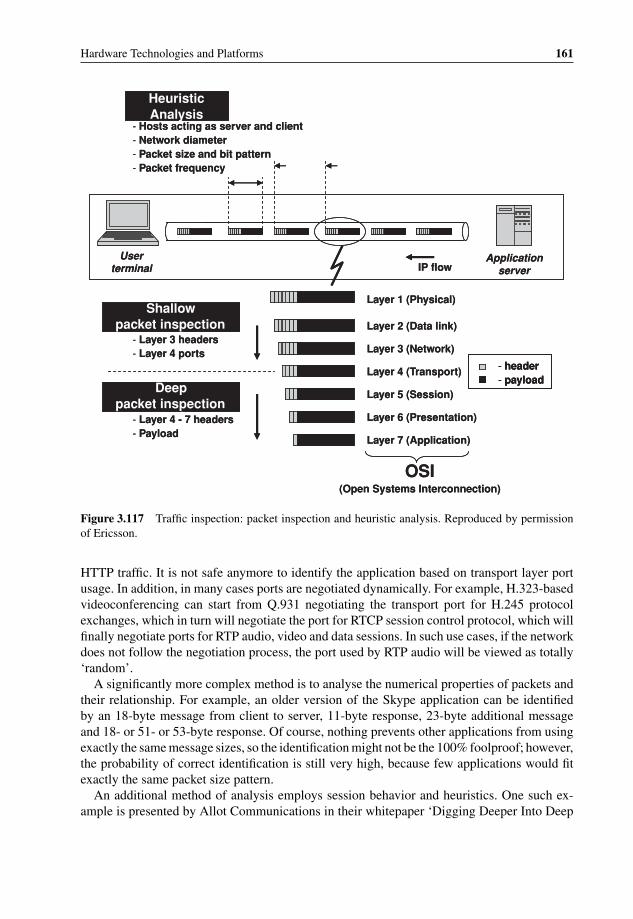
P1: OTA/XYZ P2: ABCc03 BLBK307-Bachmutsky September 2, 2010 13:12 Printer Name: Yet to Come
Hardware Technologies and Platforms 161
Heuristic Analysis
Shallow packet inspection
Deep packet inspection
- Hosts acting as server and client- Network diameter- Packet size and bit pattern- Packet frequency
- Layer 3 headers- Layer 4 ports
- 7 headersLayer 4 -- Payload
IP flowUser
terminalApplication
server
- header- payload
Layer 1 (Physical)
Layer 2 (Data link)
Layer 3 (Network)
Layer 4 (Transport)
Layer 5 (Session)
Layer 6 (Presentation)
Layer 7 (Application)
OSI(Open Systems Interconnection)
Heuristic Analysis
Shallow packet inspection
Deep packet inspection
- Hosts acting as server and client- Network diameter- Packet size and bit pattern- Packet frequency
- Layer 3 headers- Layer 4 ports
- 7 headersLayer 4 -- Payload
IP flowUser
terminalApplication
server
- header- payload- header- payload
Layer 1 (Physical)
Layer 2 (Data link)
Layer 3 (Network)
Layer 4 (Transport)
Layer 5 (Session)
Layer 6 (Presentation)
Layer 7 (Application)
OSI(Open Systems Interconnection)
Figure 3.117 Traffic inspection: packet inspection and heuristic analysis. Reproduced by permissionof Ericsson.
HTTP traffic. It is not safe anymore to identify the application based on transport layer portusage. In addition, in many cases ports are negotiated dynamically. For example, H.323-basedvideoconferencing can start from Q.931 negotiating the transport port for H.245 protocolexchanges, which in turn will negotiate the port for RTCP session control protocol, which willfinally negotiate ports for RTP audio, video and data sessions. In such use cases, if the networkdoes not follow the negotiation process, the port used by RTP audio will be viewed as totally‘random’.
A significantly more complex method is to analyse the numerical properties of packets andtheir relationship. For example, an older version of the Skype application can be identifiedby an 18-byte message from client to server, 11-byte response, 23-byte additional messageand 18- or 51- or 53-byte response. Of course, nothing prevents other applications from usingexactly the same message sizes, so the identification might not be the 100% foolproof; however,the probability of correct identification is still very high, because few applications would fitexactly the same packet size pattern.
An additional method of analysis employs session behavior and heuristics. One such ex-ample is presented by Allot Communications in their whitepaper ‘Digging Deeper Into Deep
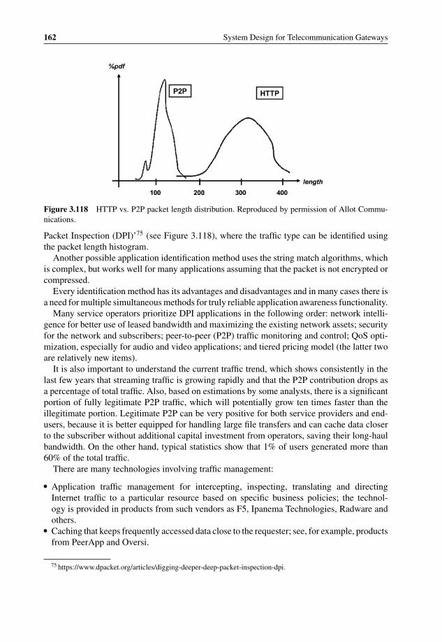
P1: OTA/XYZ P2: ABCc03 BLBK307-Bachmutsky September 2, 2010 13:12 Printer Name: Yet to Come
162 System Design for Telecommunication Gateways
Figure 3.118 HTTP vs. P2P packet length distribution. Reproduced by permission of Allot Commu-nications.
Packet Inspection (DPI)’75 (see Figure 3.118), where the traffic type can be identified usingthe packet length histogram.
Another possible application identification method uses the string match algorithms, whichis complex, but works well for many applications assuming that the packet is not encrypted orcompressed.
Every identification method has its advantages and disadvantages and in many cases there isa need for multiple simultaneous methods for truly reliable application awareness functionality.
Many service operators prioritize DPI applications in the following order: network intelli-gence for better use of leased bandwidth and maximizing the existing network assets; securityfor the network and subscribers; peer-to-peer (P2P) traffic monitoring and control; QoS opti-mization, especially for audio and video applications; and tiered pricing model (the latter twoare relatively new items).
It is also important to understand the current traffic trend, which shows consistently in thelast few years that streaming traffic is growing rapidly and that the P2P contribution drops asa percentage of total traffic. Also, based on estimations by some analysts, there is a significantportion of fully legitimate P2P traffic, which will potentially grow ten times faster than theillegitimate portion. Legitimate P2P can be very positive for both service providers and end-users, because it is better equipped for handling large file transfers and can cache data closerto the subscriber without additional capital investment from operators, saving their long-haulbandwidth. On the other hand, typical statistics show that 1% of users generated more than60% of the total traffic.
There are many technologies involving traffic management:
� Application traffic management for intercepting, inspecting, translating and directingInternet traffic to a particular resource based on specific business policies; the technol-ogy is provided in products from such vendors as F5, Ipanema Technologies, Radware andothers.
� Caching that keeps frequently accessed data close to the requester; see, for example, productsfrom PeerApp and Oversi.
75 https://www.dpacket.org/articles/digging-deeper-deep-packet-inspection-dpi.

P1: OTA/XYZ P2: ABCc03 BLBK307-Bachmutsky September 2, 2010 13:12 Printer Name: Yet to Come
Hardware Technologies and Platforms 163
� Policy control that provides a way to allocate network, QoS and security resources based ondefined business policies; see, for example, products from Camiant and Radware.
� Traffic shaping, which optimizes performance, lowers latency and increases usablebandwidth by delaying packets that meet certain criteria; see, for example, products fromBlue Coat.
� Packet filtering/traffic throttling enabling DPI-based traffic throttling at the inspection pointsin the network; see, for example, products from Sandvine, Allot, Radware, F5, Camiant,Ipanema, Nokia Siemens Networks and others.
The DPI in telecommunication systems can make such network elements subscriber-aware(for example, by offering high-end packages for subscribers who may require more capacity,better performance and reliability than a typical subscriber) and application-aware (provisionof additional bandwidth for a heavy user or based on the user’s individual habits, ensuring QoSfor subscribers using advanced applications, enforcing low latency for applications like onlinegaming, etc.; PlusNet in the UK (acquired by BT) provided a service where all gaming andVoIP traffic was prioritized, with up to 10 GB usage allowance, but allowing for free usage frommidnight to 8 am). The DPI can help build a more flexible portfolio of services, such as limitedand expanded usage packages based on subscriber awareness, tiered usage packages anddynamic bandwidth allocation based on time of day and various applications, one-time ‘boost’options for particularly bandwidth-heavy sessions, QoS assurance for all traffic from a specificuser, for the traffic of a certain type or from a certain source for a specific user, for a certainapplication across the operator’s network or for a content provider. The DPI can even drive newbusinesses: for example, targeted ad insertion on behalf of a content provider, or an advertiser;Google YouTube Video Identification identifies copyrighted video clips automatically andthen lets the owner decide what to do with that content: take it down from YouTube, keep itup without ads, or let Google run ads against it in return for a share of the advertising revenue.
On the other hand, DPI encounters many technical and non-technical challenges:
� Layer 4–Layer 7 DPI is not always feasible; for example, transport layer ports can be changedfrequently or used in a non-intended manner, the traffic can be encrypted and proxies canbe used to prevent end-point identification.
� DPI might need to be combined with flow-state analysis (port usage, traffic levels, packetsizes, flow patterns between network elements, frequency of flows, number of flows persubscriber or application, burstiness of flows, etc.) to match the traffic reliably to different ap-plication types; some vendors (Anagran, InterStream) claim that there is no need in DPI andthat flow-state analysis is enough (which in our opinion is not 100% true for some scenarios).
� The scaling factor can become a problem. AT&T has installed optical splitters in all of itsInternet data centres around the world allowing one to apply ‘AT&T Knowledge MiningServices’ for over 10 petabytes of IP traffic per day: the ‘Hawkeye’ call detail recordingdatabase that keeps records of voice calls; ‘Aurora’ or Security Event and InformationManagement; ‘Daytona’ – a massive data mining database that queries and retains recordsfor two years. At the same time, better knowledge about traffic content could reduce theneed for such huge databases.
� Network economics have demanded DPI because of erosion of the revenue per bitearned by ISPs; however, the introduction of DPI has been muted because of the de-bate over network neutrality, when users should control the content and applications, that

P1: OTA/XYZ P2: ABCc03 BLBK307-Bachmutsky September 2, 2010 13:12 Printer Name: Yet to Come
164 System Design for Telecommunication Gateways
broadband carriers should not be permitted to use their market power to discriminateagainst competing applications or content, or to control activity online and that customersshould know that operators can identify traffic and manipulate traffic streams. One obvi-ous example of potential competition is VoIP application usage, such as Skype, for mobileoperators. The economics is simple: unlimited data plane cost at AT&T in the US is $15 forregular phones, higher for smart phones, but in any case is lower than the voice plan. Basedon these economics, mobile operators are definitely not interested in allowing high qualityunlimited Skype calls for such a low cost. Another classic example is that which causedthe original network neutrality controversy with the FCC targeting Comcast’s traffic man-agement practices.76 ‘Specifically, ‘when one BitTorrent user attempts to share a completefile with another user’ via a TCP connection, Comcast’s servers (through which its users’packets of data must pass) send to each user’s computer an RST packet ‘that looks like itcomes from the other [user’s] computer’ and terminates the connection.’ These widely andcorrectly criticized actions may not be the worst possible option. For example, instead oftargeting a specific application by forcing TCP disconnect, Comcast could legally enforcethe throughput (nobody promised unlimited bandwidth) and drop any traffic burst in excessof the committed throughput. In many cases, BitTorrent applications create significant trafficbursts because of multiple concurrent independent active connections and if Comcast coulddrop packets randomly for a particular subscriber who violates the committed throughput,all UDP-based applications (such as VoIP) would be badly affected and all TCP-basedapplications, including the BitTorrent, would reduce their throughput to a minimum becauseof packet loss and corresponding TCP backoff mechanisms. In the end, VoIP quality forthat subscriber would be unacceptable and BitTorrent sessions would be so slow that largefile downloads (such as movies) would take forever to complete, putting in question thepracticality and efficiency of P2P communication. Is it a better solution for subscribers? Notreally. It would be much better, for example, to drop excess packets from only a single orlimited number of BitTorrent sessions; however, that functionality still requires knowledgeabout BitTorrent protocol usage and session awareness and monitoring.
However, a random packet drop could also affect Comcast’s video-on-demand streamingservice, but Comcast could mark that traffic as high priority either at Layer 2 or Layer 3and prioritize that traffic over others. It would be difficult to justify the rule prohibitingsuch marking for video traffic, because this is the sole reason why this priority has beencreated and used. However, the question will arise as to what happens when external trafficis also marked with a high priority. If the operator has to trust the external marking by law,very soon the entire traffic on the Internet will be marked as high priority. On the otherhand, if the operator is allowed to remark the traffic at the entrance to his network, wouldit create the same issue of net neutrality that we face today? One way is to regulate andverify QoS marking, punishing or even prosecuting end-users for illegal traffic markingsimilar to illegal use of the content. Even if such regulation is imposed, it would probablynot work efficiently. It would also not help in the situation when some data for a particularclass-of-service has to be dropped and the operator selects which one it is: from a singlesession affecting one service (most probably, not the operator’s), randomly from any sessionaffecting all services of the same class-of-service, or some mixed policy decision. It looks
76 http://www.hraunfoss.fcc.gov/edocs_public/attachmatch/FCC-08–183A1.pdf.

P1: OTA/XYZ P2: ABCc03 BLBK307-Bachmutsky September 2, 2010 13:12 Printer Name: Yet to Come
Hardware Technologies and Platforms 165
like traffic classification, including the DPI, would be useful or even required for everybodyin any case.
There is one additional important clarification: if P2P or other sessions would be encryptedto hide the application’s identity, the situation becomes worse for the subscriber. If theoperator does not deploy behavioral and statistical analysis systems in the network, it willaffect all active sessions randomly, as described above. If the operator has very sophisticatedand expensive traffic analysis tools, P2P sessions will still be detected in most cases (basedon the EANTC tests77 described in Section 3.5.5.5), but any significant packet drop froma single session would practically disconnect that session, because secured protocols aremuch more sensitive to a packet loss. As a result, the subscriber does not gain anythingand loses some capabilities. Also, data encryption makes packets larger, increasing trafficthroughput, which triggers much faster subscription bandwidth enforcement, which againaffects the end-user.
It is clear that the traffic classification element of the original Comcast solution is stillviable, only the action was incorrect. Therefore, when discussing network neutrality, it isimportant to distinguish between the content-aware traffic classification and the correspond-ing traffic management action. The former has to be as granular as possible; the latter hasto provide a legal balance between operator and subscriber needs. As Klaus Mochalski andHendrik Schulze from Ipoque stated correctly in their whitepaper ‘Deep Packet Inspection –Technology, Applications and Net Neutrality’,78 ‘Interestingly, there have been DPI-basedapplications and network functions deployed in many places across the Internet for manyyears without drawing much criticism. Here is a short list of examples: email spam filtering;anti-virus filtering for email and other Internet content; intrusion detection and preventionsystems (IDS/IPS); firewalls; content caching systems (e.g. for Web pages); and networkprobes for network monitoring and troubleshooting. All these technologies have a certainmisuse potential as they all have access to user content data. DPI-based traffic managementis just another DPI application on this list and should be treated as such’.
The problem is also very significant for mobile communication, where an additionalparameter, location, plays an important role for many content providers, such as Google.Google, one of the biggest supporters of network neutrality, is interested in the collectionof all information about subscribers, but to be used only by the application and contentproviders (like Google, of course) and not by the network providers. The paradox is that thebest entity that can collect such information is the network provider. Google’s idea is thatservice providers become only data movers, they do not own their subscribers, but own onlybitpipes. Obviously, service providers have ‘a little’ different view of the world.
It is possible to compare the discussion about subscriber ownership and DPI lookup withcredit card transactions, where credit card companies have a great deal of demographic andbehavioral information about their subscribers: age, for what and when they shop, detailedcredit scores, debt level, when and where they go for gas, health services (and frequently typesof health services), other credit cards and loans they have, payback patterns (minimum amountvs. full amount at the end of the month) and much more. Until now, they have not used (orat least not to the extent they are able to) all of that information for marketing purposes and
77 http://www.internetevolution.com/document.asp?doc_id=178633.78 http://www.ipoque.com/userfiles/file/DPI-Whitepaper.pdf.

P1: OTA/XYZ P2: ABCc03 BLBK307-Bachmutsky September 2, 2010 13:12 Printer Name: Yet to Come
166 System Design for Telecommunication Gateways
additional revenue sources. On the other hand, the comparison is not fair, because credit cardcompanies are charging the ‘content’ provider a percentage for every transaction, meaningthat with a similar business model Google would need to pay some of their revenues to thenetwork providers.
At the end of 2008, in the USA, the House passed a telecom bill without net neutralityprotections. A pro- net neutrality amendment failed in the Senate Commerce Committee,and full Senate discussions are still pending as of the time of writing. In Europe, Copen-hagen economics consultants claimed that net neutrality in Europe will significantly increasebroadband prices and depress broadband demand; and the Centre for European Policy Studiescame out against net neutrality, proposing that end-users simply have to be informed aboutrestrictions so as to be able to shop around. Australian ISPs commented that the problemdoes not exist in Australia, because traffic there is charged according to volume, minimiz-ing many of the P2P traffic issues raised in the USA and Europe. In APAC there are norestrictions and operators plan deploying DPI and offering DPI-based application-specificdifferentiated services (gaming QoS package, QoS for part of the day and others). However,in the USA (and as a result in Western Europe) DPI has had bad publicity, caused a publicoutcry and is waiting for an FCC ruling. Many operators are afraid to say that they use DPI,which is used for monitoring, not for enforcement, with subscriber awareness only, withoutturning on application awareness, while QoS for VoIP is provided free of charge. An indi-cation of the FCC’s approach was disclosed by Julius Genachowski, the FCC Chairman, inSeptember 2009 in his speech to the Brookings Institution in Washington, DC. There wasone rule mentioned that is applicable to this discussion: ‘Broadband providers cannot blockor degrade lawful traffic over their networks, favor certain content or applications over othersand cannot ‘disfavor an Internet service just because it competes with a similar service offeredby that broadband provider.’ Hopefully, it will not be as bad as suggested by Wired’s Dylan F.Tweney in his article ‘FCC Position May Spell the End of Unlimited Internet’,79 where the titlesays everything. As an indication of another level of complexity, the US Court of Appeals forthe District of Columbia ruled in April 2010 that the FCC lacks authority to require broadbandproviders to give equal treatment to all Internet traffic flowing over their networks. We hopethat whatever the solution will be, it will allow extensive innovation as opposed to curbingit in the name of consumer privacy and rights. It is noticeable fact that the publication in theGovernment Computer News in January 2010 has marked DPI as one of the technologies towatch, but mainly for security applications.
Content aware processing might need to be performed not only on a single packet, butalso on an application message that consists of multiple packets. One of the key technologiesdeveloped for that purpose is the ability to run DPI at high speeds, at nearly wire speedin some scenarios, with optional intermediate state creation between the packets of the sameapplication data stream. Regular CPUs and NPUs are not very efficient for such an application,because it requires thousands or even tens of thousands of instructions per packet as opposedto hundred(s) of instructions for simple switching or forwarding (see Figure 3.119).
Protocols and thus content processing can be divided roughly into two groups: binaryand string based. For example, Layer 2 to Layer 4 headers, ITU-T H.32x standards (audio,video, and data communications) and mobile network protocols (3G, 4G, WiMAX and manyothers) are binary; Session Initiation Protocol (SIP) and Session Description Protocol (SDP)
79 http://www.wired.com/epicenter/2009/09/fcc-neutrality-mistake/.

P1: OTA/XYZ P2: ABCc03 BLBK307-Bachmutsky September 2, 2010 13:12 Printer Name: Yet to Come
Hardware Technologies and Platforms 167
Compute Intensity
Complexity
~100 Instructions per Packet
SwitchingRouting
QoSNetwork Monitoring
Load BalancingSecure Communications
FirewallVPN
Intrusion DetectionXML Processing
Virus Scanning
High compute resources required for value-added services
Huge numbers of instructions per packet/message
Content Processing Complexity
Compute Intensity
Complexity
~100 Instructions per Packet
SwitchingRouting
QoSNetwork Monitoring
Load BalancingSecure Communications
FirewallVPN
Intrusion DetectionXML Processing
Virus Scanning
High compute resources required for value-added services
Huge numbers of instructions per packet/message
C ontent Processing Complexity
Figure 3.119 Content Processing Complexity. Reproduced by permission of LSI.
are string-based. The same is true for protocols based on ASN.1 technology80 or ExtensibleMarkup Language (XML)81 that drives the World Wide Web. String-based protocols are bydefinition very dynamic in nature and the content heavily depends on the application. Take asan example the XML description of a bread recipe from Wikipedia:82
<recipe name = ‘bread’ prep time = ‘5 mins’ cook time = ‘3 hours’>
<title>Basic bread</title>
<ingredient amount = ‘8’ unit = ‘dL’>Flour</ingredient>
<ingredient amount = ‘10’ unit = ‘grams’>Yeast</ingredient>
<ingredient amount = ‘4’ unit = ‘dL’ state = ‘warm’>Water</ingredient>
<ingredient amount = ‘1’ unit = ‘teaspoon’>Salt</ingredient>
<instructions>
<step>Mix all ingredients together.</step>
<step>Knead thoroughly.</step>
<step>Cover with a cloth, and leave for one hour in warm room.</step>
<step>Knead again.</step>
<step>Place in a bread baking tin.</step>
<step>Cover with a cloth, and leave for one hour in warm room.</step>
<step>Bake in the oven at 180(degrees)C for 30 minutes.</step>
</instructions>
</recipe>
80 http://www.asn1.org/.81 http://www.w3.org/XML/, also http://www.xml.org.82 http://www.en.wikipedia.org/wiki/XML.

P1: OTA/XYZ P2: ABCc03 BLBK307-Bachmutsky September 2, 2010 13:12 Printer Name: Yet to Come
168 System Design for Telecommunication Gateways
Version
MSID
Flags Function Type Message Type
MSIDLength
Reserved
Transaction ID Reserved
Other TLVs
Source Identifier TLV
Destination Identifier TLV
80 312416OP ID
27
Message Header
Message Body (variable size)0 n
Figure 3.120 WiMAX binary header structure (from WiMAX specification V1.2.2). Reproduced bypermission of WiMAX Forum.
An XML document can be viewed as a tree made up of seven types of nested nodes: the rootnode that contains all other nodes, element nodes, text nodes, attribute nodes, comment nodes,processing instruction nodes and namespace nodes. Nodes and sets of nodes are described oraddressed using XPath language which can be viewed as an XML document query language,or a rule language to express assertions against XML documents.
XML has become more and more popular lately because it has two main advantages: (a) asimple grammar allowing for the creation of expressive languages for a variety of applications;(b) a well-defined syntax enforced by all languages allowing for the creation of a standardsuite of processing tools. Two of the well-known tools are Document Object Model (DOM)and Simple API for XML (SAX). DOM has a richer functionality and more flexibility, butis very compute-intensive and memory-hungry. SAX is simpler and more lightweight with ahigher performance on a limited subset of XML-based processing, but even with a limitedXML set its performance is not sufficient for large and scalable applications.
The structure for binary protocols is much more rigid. For example, 4G WiMAX protocol’sfixed and dynamic headers structure is shown in Figure 3.120 (it might be not the most recent,but that does not matter for our purposes).
In order to have the required flexibility, many binary protocols have introduced a Type-Length-Value (TLV) structure which enables one to specify the type and length of the field ina binary form, while the value can be either binary, or string-based, or even another TLV tosupport nested or hierarchical parameter description. For example, one of WiMAX messages(taken from the same specification as the Figure 3.120) is defined by the message body shownin Table 3.4 (‘M’ means mandatory, ‘O’ means optional, ‘>’ means the first level of nesting(SF Info TLV is nested inside MS Info TLV), ‘>>’ means the second level of nesting (QoSParameters TLV is nested inside SF Info TLV), and ‘>>>’ means the third level of nesting(BE Data Delivery Service TLV is nested inside QoS Parameters TLV)). The advantage of the

P1: OTA/XYZ P2: ABCc03 BLBK307-Bachmutsky September 2, 2010 13:12 Printer Name: Yet to Come
Hardware Technologies and Platforms 169
Table 3.4 Service Flow Creation TLV structure (from WiMAX specification V1.2.2). Reproduced byWIMAX Forum
IE M/O Notes
Failure Indication OMS Info M>SF Info M>>SFID M SFID as defined on R1>>Reservation Result M>>QoS Parameters O This is only allowed to be present if ‘Reduced
Resources Code’ was set at the correspondingRR Req message.
>>>BE Data Delivery Service O Set to BE delivery service>>>UGS Data Delivery Service O Set to UGS delivery service>>>NRT-VR Data Delivery Service O Set to NRT-VR delivery service>>>RT-VR Data Delivery Service O Set to RT-VR delivery service>>>ERT-VR Data Delivery Service O Set to ERT-VR delivery service>>>Global Service Class Name O See IEEE802.16e for further details
TLV representation is a capability to skip the entire TLV quickly with all its child TLVs in asingle step using the length field.
Traditionally, binary protocols are processed either by NPUs or CPUs, but a flexible TLVstructure creates many challenges. Let us imagine that there is a need to find in the receivedmessage the TLV with a type equal to T1. The software would start parsing the message fromthe beginning, jumping over other TLV types until it finds type T1 at offset O1. Let us assumethat after that we also need to find a TLV with type T2. In general, this TLV can be placedin the message before the offset O1, meaning that we need to start parsing the message fromthe beginning again. And so on for every TLV. If we add the complication that TLV T1 and/orT2 can be nested inside another TLV with potentially different interpretations depending onthe level of nesting or a parent TLV, and the same TLV can sometimes appear in the samemessage multiple times with different nesting levels and parent TLVs, the parsing algorithmbecomes even more challenging. Some implementations parse the entire message once, createthe TLV hierarchy table or index and use it for further searches in the message. It helps toavoid walking through the same message fields multiple times, but on the other hand it createsa significant initial overhead that might be an overkill when the only target is to find one singlefield in the message (performing, for example, application-level forwarding) ignoring the restof the information.
Unfortunately, the acceleration technology has been concentrating on string-based contentprocessing, where special algorithms or hardware-based acceleration can achieve up to 10xspeed-up in the string search. As of the time of writing, there are no commercially availablehardware accelerator products to process TLV-based protocols more efficiently. However,there are indications that this may change soon, because several vendors are working onsuch acceleration technology. There is no doubt that this capability would bring a significantadvantage and distinction for many telecommunication designs.

P1: OTA/XYZ P2: ABCc03 BLBK307-Bachmutsky September 2, 2010 13:12 Printer Name: Yet to Come
170 System Design for Telecommunication Gateways
transition rule memory
rule selector control
state register
B-FSM
instruction handler
output
input
results
instructions
next state
current state
transition rule memory
rule selector control
state register
B-FSM
instruction handler
output
input
results
instructions
next state
current state
Figure 3.121 IBM BaRT-based finite state machine principle for XML acceleration. Reprint Courtesyof International Business Machines Corporation, © 2005 International Business Machines Corporation.
This chapter describes some of the available content processing acceleration technologiesand commercial components and products.
XML acceleration is still not a widely used functionality, but there are a number of vendorstrying to solve this problem.
In 2005 IBM acquired the XML appliance acceleration company DataPower and there areexpectations that XML acceleration technology will appear at some point of time in IBMcomponents as well as network appliances. Meanwhile, Stefan Letz and his colleagues fromIBM offer XML acceleration software running on the IBM Cell processor (see [DPI-XML-IBM] and Figure 3.122) using Balanced Routing Table (BaRT) based Finite State Machine(B-FSM), as shown in Figure 3.121.
Initial results show more than 2x performance improvement on the same reference processorwith almost 3.5x improvement on Cell processor using eight processing engines.
This is an excerpt from the proposal:
‘A key aspect of the B-FSM technology is that it is based on state transition rules that includeconditions for the current state and input values, and have been assigned priorities. In each cycle,the highest-priority transition rule is determined that matches the actual values of the state andinput. This rule is then used to update the current state and to generate output. The B-FSM conceptapplies a hash-based search algorithm, called BaRT, to find the highest-priority transition rulematching the state and input values. By exploiting BaRT in combination with several optimizationtechniques, including state clustering and encoding, the B-FSM technology is able to provide aunique combination of high performance, low storage requirements, and fast dynamic updates,while supporting large state transition diagrams and wide input and output vectors, resultingin a significant gain over conventional programmable state machine technologies. . .The XMLaccelerator supports a variety of conditions that can be specified for each transition rule. Theseconditions can relate to character information, for example, allowing direct testing of whether

P1: OTA/XYZ P2: ABCc03 BLBK307-Bachmutsky September 2, 2010 13:12 Printer Name: Yet to Come
Hardware Technologies and Platforms 171
JS20
bla
de
JS20
bla
de
JS20
bla
de
Cel
l BE
bla
de
BladeCenter
ApplicationsWebSphereApp Server
Protocol handler
XMLaccelerator
JS20
bla
de
JS20
bla
de
JS20
bla
de
Cel
l BE
bla
de
BladeCenter
ApplicationsWebSphereApp Server
Protocol handler
XMLaccelerator
Figure 3.122 IBM XML accelerator using Cell-based blade. Reprint Courtesy of International BusinessMachines Corporation, © 2005 International Business Machines Corporation.
an input character is a legal character to be used in an XML name, whether it is a white-spacecharacter, or whether it is part of a valid hexadecimal string representation. Conditions canbe specified related to the outcome of the instruction execution by the instruction handler, forexample, to determine whether a string of input characters matches a previous string of inputcharacters that have been temporarily stored in a local memory (e.g., to check for matching startand end tags). A third category of conditions relates to the detection and handling of exception anderror conditions, for example, buffer overflows. The instruction handler supports a wide range ofinstructions designed for efficient XML processing, including encoding-related instructions (e.g.,conversion from UTF-8 to UTF-16), storage, retrieval and comparison of character strings in alocal memory, searching strings in a search structure, and a flexible generation of output data.Multiple instructions can be combined in one transition rule, so that they can be executed in parallelby the instruction handler. In addition, a set of special instructions is directly executed by the B-FSM controller and enables procedure calls to subroutines defined by a collection of transitionrules.’
One of the companies that created commercial components for content processing accelera-tion was Tarari, acquired by LSI in 2007. Since then, LSI has integrated the technology in theirnetwork processors (see Section 3.5.3.2.3) and multicore CPUs. LSI Tarari technology is builtaround the Content Processing Platform which includes controller and processing engineswith their own memory interfaces for high performance.
LSI has a family of components for XML acceleration. The basis of all of these productsis the Tarari Random Access XML (RAX) architecture, which is based on the SimultaneousXPath engine which produces results directly from the input XML document. The engine’sperformance is independent on a number of XPaths or a complexity of XPath expressions andis linear with file size. Of course, it is difficult to even compare hardware accelerated XMLprocessing using LSI Tarari RAX with software based implementation, because the hardwareachieves close to 100x performance improvement, all without loading the main CPU and withmuch lower power usage.
At the same time, there is a great deal of effort aimed at offering a range of solutions forregular expression acceleration that are reviewed in this chapter.
P1: OTA/XYZ P2: ABCc03 BLBK307-Bachmutsky September 2, 2010 13:12 Printer Name: Yet to Come
172 System Design for Telecommunication Gateways
3.5.5.1 Regular Expression Technology
Regular expression, or RegEx, is a language that describes text patterns, invented by theAmerican mathematician Stephen Kleene.
Dan Appleman comments in his e-book ‘Regular Expressions with .NET’ on RegEx: ‘Alanguage that is terse to such a degree that the term ‘concise’ does not come close to describingits brevity of syntax. A language so cryptic that it can take hours to truly understand a singleline of code. Yet it is a language that can save you hours upon hours of time in any applicationthat involves text processing or data validation. It is a language that can perform complex datavalidation tasks in a single line of code. It is a language that performs sophisticated searchand replace operations on strings. It is a language that should be part of every programmer’stoolbox’.
A list of applications that benefit from regular expression technology includes IntrusionDetection/Prevention Systems (IDS/IPS), anti-spam protection, SMTP (e-mail) and HTTP(e-mail and Web) content based load balancing/forwarding/filtering, anti-virus protection,content aware billing and many others.
RegEx can follow either a basic (BRE) or extended IEEE POSIX 1003.2 ERE specification.The pattern, or search expression, can be represented by one or more ‘regular’, or literal,characters and zero or more special metacharacters. Literal characters are used to define theexact matching text; for example, ple will be matched in the word ‘example’, but not in theword ‘plumber’; literal characters are case sensitive by default. Match can be greedy, whenthe match is trying to find the longest possible match, or non-greedy, or lazy (other termsused for the same functionality are reluctant, minimal, or ungreedy), when the match is tryingto find the shortest possible match. Metacharacters are used to define special meanings. Thefollowing are just a few examples of metacharacters:
� \xAB (represents hexadecimal value AB, similar to 0xAB in some programming languages),\n (Line Feed, or LF character), \r (CR character), \t (tab), \v (vertical tab), \cA (CTRL-A,similarly other CTRL sequences are defined), \d (all digits), \w (word character – all lettersand digits), \s (whitespace), \D (all characters except digits), \W (everything except lettersand digits), \S (not a whitespace).
� [pattern] square brackets define the character class, classes can be nested; class matches asingle character out of all possibilities defined by a class; for example, [abc] matches a, b,or c.
� \Qliteral\E searches for the exact text between \Q and \E metacharacters ignoring anyspecial character meaning in that text.
� (hyphen) defines a range of values (except when it is used right after the character class startdefined by opening square bracket); for example, [a-f] defines a range of characters from ato f .
� ˆ (caret) immediately after the square bracket opening negates the corresponding characterclass, causing it to match a single character not listed in the character class; for example,[ˆa-f] defines a set of characters except those in the range from a to f . If the caret is notused immediately after the opening square bracket, it defines the start of the string (or inmany implementations can be configurable to include the start of the line); for example,ˆ. (see also dot character below) will match the first character in the string (or the line);the metacharacter that is performing the same function without multiline capability is \A.

P1: OTA/XYZ P2: ABCc03 BLBK307-Bachmutsky September 2, 2010 13:12 Printer Name: Yet to Come
Hardware Technologies and Platforms 173
The opposite for such caret use is the $(dollar) metacharacter, which defines the string(or the line) last literal character; similar metacharacter without multiline capability is the\z. Practically, these metacharacters match the position as opposed to any character. Twoother examples of position-matching metacharacters are \b (position between a word and anon-word characters) and \B (position between two word or two non-word characters).
� . (dot) matches any single character except \n and \r (in some implementations \n and \rare also optionally included as a configuration parameter)
� | (pipe) matches the text either on left or right side of the pipe; for example, ramp(up|down)will match either rampup or rampdown strings.
� ? (question mark) makes the preceding item optional; it is a greedy search, similar lazysearch is defined by using a dual question mark ??.
� * (star) repeats the previous item zero or more times (similar to a wildcard usage in filenames; it is a greedy search, similar lazy search is defined by a sequence of a star followedby the question mark ∗?.
� + (plus) and +? (plus and the question mark) are similar to a star usage (greedy and lazy),but the pattern has to be included at least once.
� {n} repeats the previous item exactly n times; for example, (do){3} will match ‘dododo’(round brackets define a grouping functionality). The pattern {n,m} works similarly, butaccepts the item repeated between n to m times (it is a greedy search, similar lazy searchis defined by adding a question mark: {n,m}?). If the replication has to be defined to be atleast n times (as opposed to exactly n times), the matching greedy expression is {n,} andlazy expression is {n,}?.
� \1 through \9 defines a back-referenced item number; for example, ramp(up|down)\1will match rampupup or rampdowndown strings, but will not match rampupdown or ramp-downup. Some implementations do not have back-reference feature and use \n metacharacterto specify octal numbers; for example, in such implementation \123 would mean octal value123.
� (?modifier) modifies the match rules until the end of the RegEx; for example, (?i) turns oncase sensitivity, and (?-i) turns case sensitivity off; there are many other modifiers.
� (?#comment) adds comments to the regular expression and is ignored by the processingengine.
There are, of course, many other metacharacters and RegEx patterns (lookahead, lookback,conditional if-then-else matches, to mention a few) that were not listed above. It is easy to finda great deal of material online83 or in printed publications, such as [REGEXP-Friedl].
Some implementations have their own additional metacharacters. For example, one of thebest known grep utility84 has added the following expressions to support many character sets(examples are provided using ASCII encoding, but the generic naming convention makes themapplicable for different languages and encoding schemes):
� [:lower:] defines lower case letters; assuming English alphabet it is a set of ‘a b c d e f g h ij k l m n o p q r s t u v w x y z’.
83 for example, http://www.regular-expressions.info.84 http://www.gnu.org/software/grep/doc/.

P1: OTA/XYZ P2: ABCc03 BLBK307-Bachmutsky September 2, 2010 13:12 Printer Name: Yet to Come
174 System Design for Telecommunication Gateways
� [:upper:] defines upper case letters: ‘A B C D E F G H I J K L M N O P Q R S T U V W XY Z’.
� [:digit:] defines a set of decimal digits: ‘0 1 2 3 4 5 6 7 8 9’.� [:xdigit:] defines a set of hexadecimal digits: ‘0 1 2 3 4 5 6 7 8 9 A B C D E F a b c d e f’.� [:alpha:] defines all alphabetic characters; combines ‘[:lower:]’ and ‘[:upper:]’.� [:alnum:] defines all alphanumeric characters; combines ‘[:alpha:]’ and ‘[:digit:]’; in ASCII
can be represented by ‘[0–9 A-Za-z]’.� [:punct:] defines all punctuation characters: ! ‘ # $% & ’ () ∗ +, –. / :; < = > ? @ [\] ˆ ’{|} ∼.
� [:graph:] defines graphical characters; combines ‘[:alnum:]’ and ‘[:punct:]’.� [:print:] defines all printable characters; combines ‘[:alnum:]’, ‘[:punct:]’ and space.� [:blank:] defines blank characters: space and tab.� [:space:] defines space characters: tab, newline, vertical tab, form feed, carriage return and
space.� [:cntrl:] defines all control characters; in ASCII they have octal codes 000 through 037, and
177 (DEL).
Grep documentation provides a good and impressive example of a search pattern for allpalindrome words (reading the same forwards and backwards) up to nineteen charac-ters long (proposed by Guglielmo Bondioni): ‘ˆ(.?)(.?)(.?)(.?)(.?)(.?)(.?)(.?)(.?).?\9\8\7\6\5\4\3\2\1$’.
While the main use of regular expressions is to analyse text content, it can be also usedfor the binary content because of the capability to represent hexadecimal values through \xmetacharacter. LSI has provided an example of such procedure in one of their whitepapers.
SQL Slammer attacked Microsoft SQL servers by sending a single UDP packet to port1434. An intrusion detection system (IDS) can detect this attack by examining the contents ofthe UDP packet using a regular expression. The table in Figure 3.123 shows the elements of apacket that is a characteristic of SQL Slammer attack.
All of the regular expressions in Figure 3.123 are stated relative to the first byte of thepacket assuming that the length of the IP header has been normalized to 24 bytes. When thestatements are combined and adjusted relative to each other, the resulting regular expressionstatement becomes:
\ˆ.{9}\x11.{16}\x05\x9a.{4}\x68\x2e\x64\x6c\x6c\x68\x65\x6c\x33\x32\x68\x6b\x65\x72\x6e
Regular ExpressionPacket data and positionReal World
^.{9}\x11Hex 11 in byte 10Protocol: UDPHex 059A in bytes 27 and Port: 143428
^.{26}\x05\x9a
Data: 682E 646C Same hex values starting 6C68 656C 3332 at byte 33686B 6572 6E
^.{32}\x68\x2e\x64\x6c\x6c\x68\x65\x6c\x33\x32\x68\x6b\x65\x72\x6e
Figure 3.123 Regular Expression to identify SQL Slammer attack. Reproduced by permission of LSI.
P1: OTA/XYZ P2: ABCc03 BLBK307-Bachmutsky September 2, 2010 13:12 Printer Name: Yet to Come
Hardware Technologies and Platforms 175
Huge RegEx complexity (as can be seen in the examples above) with even bigger potentialfor content processing have created an opportunity for component and system vendors to offercommercial RegEx offload solutions.
All RegEx software and hardware implementations can be divided into three groups: usingNondeterministic Finite Automaton (NFA), using Deterministic Finite Automaton (DFA), ora hybrid of NFA and DFA. The purpose of every implementation is to compile the RegEx intoan automaton, or a state machine.
Many popular software implementations (Perl, Java, .NET, PHP, Python, Ruby, Emacsand many others) use a traditional NFA. The NFA algorithm is driven by the expressionto be matched. The algorithm starts at the beginning of the regular expression and tries tomatch it against the text from the beginning of the text, advancing through the text until bothmatch. When this happens, the algorithm advances to the next RegEx element. When there aremultiple choices to continue (for example, in the case of alternation, optional quantifier, etc.),the algorithm remembers all of the choices together with the corresponding location in thetext, selects one of choices and continues matching; if the match of that choice fails at somepoint later, the algorithm backtracks to the last saved ‘forking’ point and selects another choiceto walk through (greedy expressions prefer another match over skip, lazy expressions preferthe skip over another match), until it finds a match; if all of the choices fail, the algorithmmoves to the next character. If the algorithm matches everything at the end of the RegEx, itdecides upon the successful match and ignores all of the unprocessed choices; it means thatthe selection of the next choice is critical and the greedy or lazy match requirement may notalways be achieved. To solve the problem, the extended POSIX NFA algorithm continues toprocess all of the choices even after finding the match until all of the choices are processed,but it pays a heavy performance price for this additional functionality.
Obviously, the performance of the NFA algorithm depends heavily on the amount of back-tracking and the alternative path selection: the algorithm can walk through the same statemany times if the state is reachable via different paths running exponentially slowly in theworst case. There are a number of techniques that enable optimizing the RegEx so as to min-imize backtracking. Jeffrey Friedl describes such techniques in his book Mastering RegularExpressions ([REGEXP-Friedl]). One of them is the ‘unrolling the loop’, which is based onthe assumption that one alternate is more probable than others; the author also defines someadditional rules that have to be followed, making sure that the algorithm converges.
The DFA algorithm is driven by the text as opposed to the RegEx-driven NFA. It advancesthrough the text character-by-character (see the example in Figure 3.124, which shows DFArepresented by a state machine diagram for the search of strings ‘splice’, ‘split’ and ‘literal’;the diagram is simplified to show only the relevant states) and keeps a number of simultaneousmatches (performed in parallel) as it progresses through the text. It never backtracks and thusnever accesses the same character more than once. The DFA is much more performance-efficient than NFA and achieves very deterministic results, because given a current state(and there is a finite number of states) and an input, the automaton can move only to theone next state. On the other hand, DFA has a few disadvantages also: it always returnsthe longest match independent of how the RegEx is written. All repeating operators aregreedy; lookarounds (both forwards and backwards), capturing and back-references cannot besupported. RegEx compilation is more complex, and thus takes longer; compiled RegEx canbe memory-intensive, especially when wildcard, wildcard repetitions (‘.∗’, wildcard repeatedany number of times) or distance metacharacters are used; in some scenarios the DFA has

P1: OTA/XYZ P2: ABCc03 BLBK307-Bachmutsky September 2, 2010 13:12 Printer Name: Yet to Come
176 System Design for Telecommunication Gateways
0
1
2
3
4
5
6
7
8
9
10
12
11
13
14
s
p
l
i
a
e
t
ee
t
l
i
r
l
i
c
0
1
2
3
4
5
6
7
8
9
10
12
11
13
14
s
p
l
i
a
e
t
ee
t
l
i
r
l
i
c
Figure 3.124 DFA graph example for ‘splice’, ‘split’ and ‘literal’. Reproduced by permission ofCavium.
an exponentially greater number of states compared to a corresponding NFA. For example,the RegEx ‘text1.{200}text2’, which matches only when text1 is separated from text2 by 200characters, would require millions of DFA states (for comparison, a number of states in NFAwould be equal to 201+length(text1)+length(text2)). Is it a special and unrealistic use case?Yes and no. For example, Michela Becchi from Washington University in St.Louis in thepresentation ‘Deep Packet Inspection: Where are We?’85 at CCW’08 provided some Snortstatistics as of November 2007: 8536 rules, 5549 Perl Compatible Regular Expressions; 99%with character ranges ([c1-ck],\s,\w. . .); 16.3% with dot-star terms (.∗, [ˆc1.. ck]∗); 44% withcounting constraints (.{n. m}, [ˆc1.. ck]{n,m}). This means that the choice between NFA andDFA is in practice a choice between performance and a memory usage.
Hardware acceleration of the DFA RegEx engine is included in many Cavium Net-works OCTEON Plus multicore processors. It has three main components: a low memoryDRAM controller with support of up to 1 GB of attached RLDRAM memory, sixteen DFAthread engines (DTEs) and instruction input logic with an instruction queue. It connectsto two external 18-bit low latency DRAM interfaces (Toshiba’s FCRAM-II and Micron’sRLDRAM-II devices with access time as low as 20 ns are supported) clocked at the corefrequency, the I/O bridge (IOB) and cores (see Figure 3.125).
The DTE’s responsibility is to traverse DFA graphs in the low-latency memory. Cores submitDFA instructions through the DFA instruction queue using two modes: hardware-assist mode,when instructions and results are placed into the main memory; and direct mode, when coresuse special instructions to access low-latency memory directly. The direct mode is intended
85 http://www.netsec.colostate.edu/ccw08/Slides/becchi.ppt.

P1: OTA/XYZ P2: ABCc03 BLBK307-Bachmutsky September 2, 2010 13:12 Printer Name: Yet to Come
Hardware Technologies and Platforms 177
Co
re
Co
re
IO
DFA Input Request Q-Packet Data-Results
HW DFA Engines
Doorbell
Cac
he
/ DR
AM
IO B
us
Controller
RLDRAM/FCRAM
RLDRAM/FCRAM
DFAGraph
Tables
Co
re
Co
re
IO
DFA Input Request Q-Packet Data-Results -
HW DFA Engines
Doorbell
Cac
he
/ DR
AM
IO B
us
Controller
RLDRAM/FCRAM
RLDRAM/FCRAM
DFAGraph
Tables
Figure 3.125 OCTEON DFA implementation block diagram. Reproduced by permission of Cavium.
for use by those developers who wish to develop their own proprietary or enhanced DFAgraph/node definitions, which are outside the scope of the ‘standard’ hardware assist mode.Each instruction is scheduled to the next available DTE out of a pool of sixteen DTEs, whichwill perform in parallel fetching packet data from L2 cache or external memory via IOB,traversing to the next DFA graph state for the byte and writing intermediate and final resultsback to the L2 cache or external memory via IOB.
Software (a Cavium-provided compiler) is responsible for building the DFA graphs whichare written into the DFA memory. To provide efficient implementation for different graphsizes, the OCTEON hardware supports two graph types. The most common graph type usedis the DFA 18-bit graph mode, where each node consists of 256 pointers, or arcs. This graphtype is limited to 128 K nodes (multiple graphs may exist in the DFA memory) and each nodeconsumes 512 bytes. For applications that require graphs with more than 128 K nodes, the36-bit graph mode is supplied. This is conceptually similar to the 18-bit mode, but each nodehas 24 bits of node index, allowing 16 M nodes, and each node is 1024 bytes.
Cavium Networks DFA hardware implementation obtains software assistance for statefulregular expression searches across multiple packets, which are facilitated by the CaviumContent Search Macro (CCSM) library. The library also enables conditional searches, includingsearches based on connection state, offset, range of offsets from the previous match, distancefrom the previous match, or within a specific depth in the data stream. Hierarchical protocolssupport is also offered through the CCSM library.
There are a number of hybrid DFA/NFA implementations. Some of them (for example, GNUgrep) are relatively simple and they select NFA when some of the NFA features are required anduse DFA otherwise. Another group of implementations (one of them is, for example, GNU awk)

P1: OTA/XYZ P2: ABCc03 BLBK307-Bachmutsky September 2, 2010 13:12 Printer Name: Yet to Come
178 System Design for Telecommunication Gateways
Fast path state
memoryC
statef
Slow path memory
states
εC
Slow path automata
εBbits/sec
B bits/sec
Fast path automata
Figure 3.126 Fast Path and Slow Path processing. Reproduced by UC San Diego.
can pre-check the match using DFA (full or only partial match) and then find the required matchusing NFA. The scheme is vulnerable to DoS attack, when an attacker slows processing bysending traffic designed to fail pre-check and causing expensive regular expression processing.Yet another group (see, for example, [REGEXP-Yu]) can transform RegEx into multiple DFAsinstead of a single one. Michela Becchi describes in [REGEXP Becchi] Hybrid FA, whereany nodes that would cause the state explosion remain in NFA, the rest are transformed intoDFA, achieving small NFA-like memory footprint and high DFA-like performance. In somecases modules/nodes can even be compiled dynamically on-demand allowing for faster rulechange and smaller memory footprint.
Selection of the preferred RegEx engine is not straightforward, because of potentiallydifferent product requirements. In the worst case scenario, the NFA can be slow to the order ofO(n2m) with m regular expressions of length n, and the DFA can be memory-inefficient withthe storage requirements to the order of O(�nm).
Another solution, or more exactly a set of solutions, is described by Sailesh Kumar,Balakrishnan Chandrasekaran, and Jonathan Turner from Washington University and GeorgeVarghese from UC San Diego in their article ‘Curing Regular Expressions Matching Al-gorithms from Insomnia, Amnesia, and Acalculia’ presented at ANCS’07 in December,2007, in Orlando, Florida.86 The authors identified three major problems with existing RegExprocessing:
� Insomnia: Inability of the traditional pattern matchers to isolate frequently visited portions ofa signature from the infrequent ones; together with that, the infrequently visited tail portionsof the RegEx are generally complex (containing closures, unions, length restrictions) andlong (more than 80% of the signature) with the size of the DFA being exponential in thelength and complexity of an expression.
To solve this problem, authors propose splitting the RegEx into Fast Path that is matchedfrequently and Slow Path that is rarely accessed (see Figure 3.126).
86 http://www.cs.ucsd.edu/∼varghese/PAPERS/ancs2007.pdf.
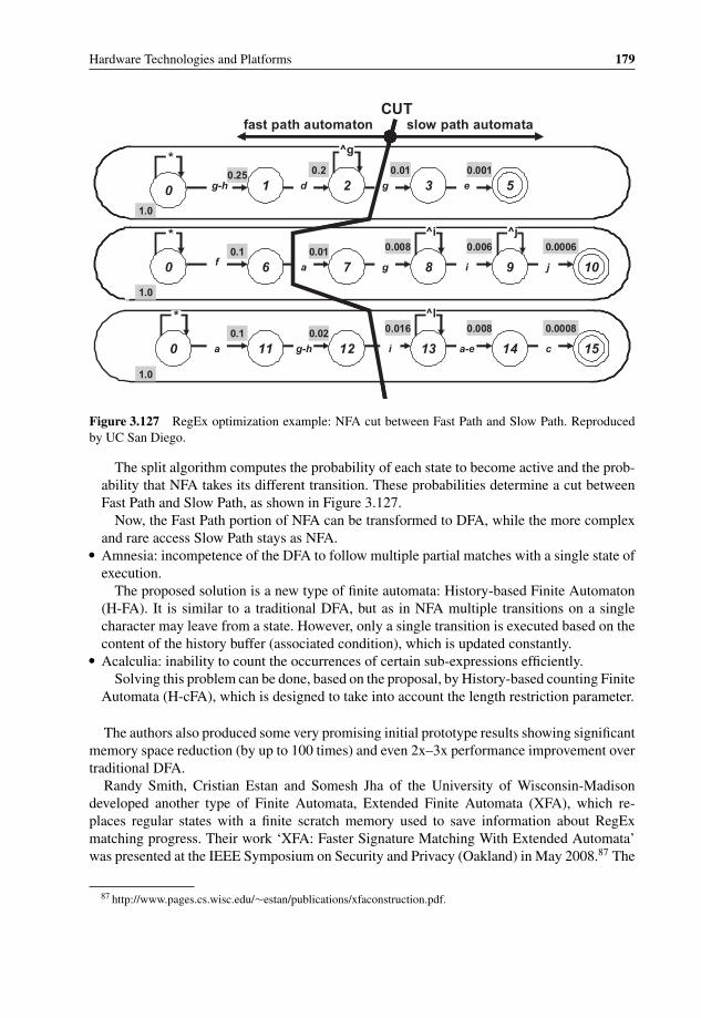
P1: OTA/XYZ P2: ABCc03 BLBK307-Bachmutsky September 2, 2010 13:12 Printer Name: Yet to Come
Hardware Technologies and Platforms 179
0
0
0
1 2 3 5
6 7 8 9
11 12 13 14
10
15
g-h d g e
f a g i j
a g-h i a-e c
1.0
1.0
1.0
0.25
0.1
0.1
0.2
0.01
0.02
0.01
0.008
0.016
0.001
0.006
0.008
0.0006
0.0008
CUTslow path automatafast path automaton
*
*
*
^g
^l
^j^i
Figure 3.127 RegEx optimization example: NFA cut between Fast Path and Slow Path. Reproducedby UC San Diego.
The split algorithm computes the probability of each state to become active and the prob-ability that NFA takes its different transition. These probabilities determine a cut betweenFast Path and Slow Path, as shown in Figure 3.127.
Now, the Fast Path portion of NFA can be transformed to DFA, while the more complexand rare access Slow Path stays as NFA.
� Amnesia: incompetence of the DFA to follow multiple partial matches with a single state ofexecution.
The proposed solution is a new type of finite automata: History-based Finite Automaton(H-FA). It is similar to a traditional DFA, but as in NFA multiple transitions on a singlecharacter may leave from a state. However, only a single transition is executed based on thecontent of the history buffer (associated condition), which is updated constantly.
� Acalculia: inability to count the occurrences of certain sub-expressions efficiently.Solving this problem can be done, based on the proposal, by History-based counting Finite
Automata (H-cFA), which is designed to take into account the length restriction parameter.
The authors also produced some very promising initial prototype results showing significantmemory space reduction (by up to 100 times) and even 2x–3x performance improvement overtraditional DFA.
Randy Smith, Cristian Estan and Somesh Jha of the University of Wisconsin-Madisondeveloped another type of Finite Automata, Extended Finite Automata (XFA), which re-places regular states with a finite scratch memory used to save information about RegExmatching progress. Their work ‘XFA: Faster Signature Matching With Extended Automata’was presented at the IEEE Symposium on Security and Privacy (Oakland) in May 2008.87 The
87 http://www.pages.cs.wisc.edu/∼estan/publications/xfaconstruction.pdf.

P1: OTA/XYZ P2: ABCc03 BLBK307-Bachmutsky September 2, 2010 13:12 Printer Name: Yet to Come
180 System Design for Telecommunication Gateways
Regular ExpressionProcessor
CPXExpansion
Bus 1
CPXExpansion
Bus 2
Central Switch
DDR2Memory
Controller
Multistream, Flow-through Controller
PCIe 8 lane
Content Processing Controller
(CPC)
Figure 3.128 LSI Tarari T2000 Regular Expression Processor. Reproduced by permission of LSI .
scheme can be useful, especially in processors with built-in low latency scratch memory orwith a capability to use the cache as a scratch pad.
An interesting approach is proposed by Brodie and colleagues in [REGEXP-Brodie], whichis based on a principle that takes multiple bytes at a time for higher throughput. The authorsestimate that it would be possible to implement the algorithm with 16 Gbps throughput onASIC clocked at 500 MHz; their initial 133 MHz Xilinx Virtex-II FPGA prototype with eightparallel engines and four bytes processing per cycle achieved impressive 4 Gbps throughput.
Many of the algorithms described above are still at the research level, but there has lately beensignificant effort to make RegEx processing more efficient. Some solutions have already foundtheir place in commercial products; others can be optimized and implemented in specializedFPGAs and ASICs.
3.5.5.2 LSI Tarari Regular Expression Acceleration Content Processors
LSI has multiple solutions for RegEx acceleration. The T1000 family of products has RegExprocessing capability with up to 3 Gbps of real-time regular expression scanning. Higherperformance family of products, T2000 (see Figure 3.128 for its block diagram), can achieveup to 10 Gbps of RegEx processing with maximum 10 W of power at such performanceand also supports dual-mode with two interconnected chips (see Figure 3.129) for combinedperformance of up to 16 Gbps.
T2000T2000(optional)
DRAMOptional
DRAM
Optional FPGA-basedExternal Agents
(Crypto, Compression,XML. Custom)
PCIe Bus 8-lane
CPX Expansion Bus 1
CPX Expansion Bus 2
Figure 3.129 LSI Tarari T2000 dual-mode system. Reproduced by permission of LSI.

P1: OTA/XYZ P2: ABCc03 BLBK307-Bachmutsky September 2, 2010 13:12 Printer Name: Yet to Come
Hardware Technologies and Platforms 181
CN1710DDR2
DDR2
DDR2
DDR2
OCTEONCN56XX
XAUI
144 bits
DRAM DDR II
PCIe x4 lanes
PCIe x8 lanes
16 bits wide DDR2-450
4 interfaces
Figure 3.130 Cavium Networks standalone hybrid DFA/NFA RegEx engine. Reproduced by permis-sion of Cavium.
In addition to high performance, T2000 supports up to 1 million RegEx rules simultaneously(with on-the-fly hot rule update and incremental rules compilation) at deterministic speedswith up to 4 million data stream contexts. It can perform a cross-packet inspection (partialmatch in one packet with the remaining match in another packet) and implements the hybridDFA/NFA technology to support complex expressions efficiently.
3.5.5.3 Cavium Networks Hybrid DFA/NFA RegEx engine
The Cavium Networks second generation RegEx engine (the first DFA-based engine has beendescribed above) implements a hybrid DFA/NFA approach. The engine appears as a built-inacceleration unit in the OCTEON-II CN6XXX family and is also available in a standaloneversion for OCTEON Plus processors. The standalone version, CN1710 (there are also thesmaller devices CN1701 and CN1705),88 is the best fit for the new generation of OCTEONPlus processor, which is based on the PCIe interface as opposed to earlier PCI and PCI-Xconnectivity (see Figure 3.130). Of course, it can be used with any other PCIe-based CPU tooffload regular expression searches.
The main functionality of the engine is integrated into the new HFA Thread Engine (HTE),which is instantiated twelve times for the required performance and scalability (see the CN1710block diagram in Figure 3.131). Multiple instances process packets simultaneously and eachHTE is implemented as a run-till-completion module. The correct instance is scheduledinternally to avoid head-of-the-line blocking and minimize graph cache thrashing and engineidle cycles. The CN1710 feature set includes an unlimited number of rule-sets and number of
88 http://www.caviumnetworks.com/NITROX-DPI_CN17XX.html.
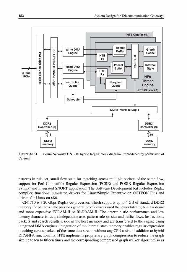
P1: OTA/XYZ P2: ABCc03 BLBK307-Bachmutsky September 2, 2010 13:12 Printer Name: Yet to Come
182 System Design for Telecommunication Gateways
Write DMA Engine
Read DMA Engine
Instruction Queue
Scheduler
DDR2 Interface Logic
DDR2 Controller (3)
DDR2 memory
16
DDR2 Controller (0)
DDR2 memory
16P
CI E
xpress In
terface Lo
gic
PC
I Exp
ress Co
re Blo
ck
8 lane PCIe
(HTE Cluster # N)
HTE Tx
HTE Rx
Result Buffer
Result Buffer
Packet Buffer
Packet Buffer
Request Queue
Graph Cache
Internal State
HT
E C
ore
HFA Thread Engine
(HTE Cluster # 0)
Figure 3.131 Cavium Networks CN1710 hybrid RegEx block diagram. Reproduced by permission ofCavium.
patterns in rule-set, small flow state for matching across multiple packets of the same flow,support for Perl Compatible Regular Expression (PCRE) and POSIX Regular ExpressionSyntax, and integrated SNORT application. The Software Development Kit includes RegExcompiler, functional simulator, drivers for Linux/Simple Executive on OCTEON Plus anddrivers for Linux on x86.
CN1710 is a 20 Gbps RegEx co-processor, which supports up to 4 GB of standard DDR2memory for patterns. The previous generation of devices used the lower latency, but less denseand more expensive FCRAM-II or RLDRAM-II. The deterministic performance and lowlatency characteristics are independent as to pattern rule-set size and traffic flows. Instructions,packets and search results reside in the host memory and are transferred to the engine usingintegrated DMA engines. Integration of the internal state memory enables regular expressionmatching across packets of the same data stream without any CPU assist. In addition to hybridDFA/NFA functionality, HTE implements proprietary graph compression to reduce the graphsize up to ten to fifteen times and the corresponding compressed graph walker algorithm so as

P1: OTA/XYZ P2: ABCc03 BLBK307-Bachmutsky September 2, 2010 13:12 Printer Name: Yet to Come
Hardware Technologies and Platforms 183
to minimize memory access. The walker also generates a large amount of statistics includinggraph transitions details, cache and memory access details and number of rescans.
3.5.5.4 NetLogic NETL7TM Knowledge-Based Processor Family
NetLogic NETL7 knowledge-based processors (KBPs) are capable of performing up to20 Gbps content inspection of packets travelling through the network. In contrast to someother content inspection devices, KBPs are designed to be positioned as a look-aside chipas opposed to in-line processing. This means that the NetLogic implementation assumes thatinitially packets are processed by another host processor, such as CPU or NPU, and are thenpassed to KBP with an additional proprietary header and the processing instructions, includingwhere to start DPI search, where and when to stop it, how to deliver results and others.
Look-aside design has its own advantages and disadvantages. On the one hand, it requiresanother processing element. On the other, it enables potentially more efficient implementationof network processing and content processing functionality and a great deal of flexibility withdifferent sets of patterns, multiple search paths through the chip and so on.
KBP includes the following features:
� Single chip with on-chip database storage to minimize system cost and board space.� Full content inspection across packet boundaries to reduce security vulnerabilities.� Intelligent Finite Automata (IFA) for efficient database scaling, which enables relatively
low 1 W per Gbps power consumption and eliminates external memory components whileenhancing performance, database flexibility and compilation speed for the largest and mostcomplex intrusion prevention, intrusion detection, anti-virus and application classificationdatabases with the support for Perl-Compatible Regular Expression (PCRE) and 100,000sof signatures.
� Fast rule compiler and device drivers, with in-service rule updating and uploading.� DoS attack prevention features.
The newest line of KBP devices, namely NLS1005/NLS1008/NLS2008, adds a number ofadditional and enhanced features:
� Separate data (XAUI) and control (PCIe) plane connectivity.� The 3rd generation IFA engine supports deterministic processing at over 2 Gbps per flow
with no back-tracking, performance compromises or practical signature length restrictions.The architecture uses an array of custom processor elements each tightly coupled with localrule memory and interconnect to other processor elements achieving over 2000 Tbps ofon-chip memory bandwidth avoiding the limitations inherent in hardware DFA and NFAsolutions. Its other properties are:– Sixteen identical processing engines operate simultaneously on individual packets or job
requests.– The processing operations available are identical regardless of the originating interface
for the packet (XAUI or PCI Express).– The application must ensure that at least sixteen unique flows are providing input data to
the device to avoid idling various engine components.
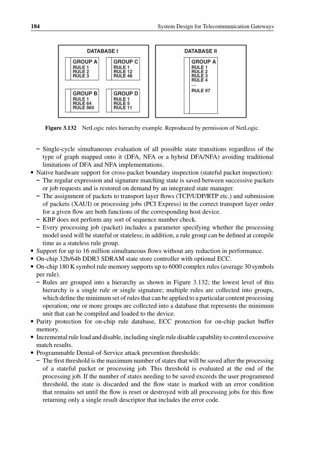
P1: OTA/XYZ P2: ABCc03 BLBK307-Bachmutsky September 2, 2010 13:12 Printer Name: Yet to Come
184 System Design for Telecommunication Gateways
GROUP ARULE 1 RULE 2 RULE 3
GROUP CRULE 1 RULE 12 RULE 48
GROUP BRULE 1 RULE 64 RULE 965
GROUP DRULE 1 RULE 5 RULE 11
GROUP ARULE 1 RULE 2 RULE 3 RULE 4 …RULE 97
DATABASE IIDATABASE I
Figure 3.132 NetLogic rules hierarchy example. Reproduced by permission of NetLogic.
– Single-cycle simultaneous evaluation of all possible state transitions regardless of thetype of graph mapped onto it (DFA, NFA or a hybrid DFA/NFA) avoiding traditionallimitations of DFA and NFA implementations.
� Native hardware support for cross-packet boundary inspection (stateful packet inspection):– The regular expression and signature matching state is saved between successive packets
or job requests and is restored on demand by an integrated state manager.– The assignment of packets to transport layer flows (TCP/UDP/RTP etc.) and submission
of packets (XAUI) or processing jobs (PCI Express) in the correct transport layer orderfor a given flow are both functions of the corresponding host device.
– KBP does not perform any sort of sequence number check.– Every processing job (packet) includes a parameter specifying whether the processing
model used will be stateful or stateless; in addition, a rule group can be defined at compiletime as a stateless rule group.
� Support for up to 16 million simultaneous flows without any reduction in performance.� On-chip 32b/64b DDR3 SDRAM state store controller with optional ECC.� On-chip 180 K symbol rule memory supports up to 6000 complex rules (average 30 symbols
per rule).– Rules are grouped into a hierarchy as shown in Figure 3.132; the lowest level of this
hierarchy is a single rule or single signature; multiple rules are collected into groups,which define the minimum set of rules that can be applied to a particular content processingoperation; one or more groups are collected into a database that represents the minimumunit that can be compiled and loaded to the device.
� Parity protection for on-chip rule database, ECC protection for on-chip packet buffermemory.
� Incremental rule load and disable, including single rule disable capability to control excessivematch results.
� Programmable Denial-of-Service attack prevention thresholds:– The first threshold is the maximum number of states that will be saved after the processing
of a stateful packet or processing job. This threshold is evaluated at the end of theprocessing job. If the number of states needing to be saved exceeds the user programmedthreshold, the state is discarded and the flow state is marked with an error conditionthat remains set until the flow is reset or destroyed with all processing jobs for this flowreturning only a single result descriptor that includes the error code.
P1: OTA/XYZ P2: ABCc03 BLBK307-Bachmutsky September 2, 2010 13:12 Printer Name: Yet to Come
Hardware Technologies and Platforms 185
– The second threshold is the maximum number of results allowed per-job or per-packet.When returning results over PCI Express, the bus bandwidth is rarely a problem; ratherthe ability of the host application to process an excessive number of results may be ofconcern. When returning results over XAUI, in addition to the host’s ability to processa large number of results, the bandwidth may become a concern as the entire packet isreturned, plus results. If the number of results generated for a job exceeds the trigger,the flow state is marked with an error condition that remains set until the flow is reset orterminated with all processing jobs for this flow returning only a single result descriptorthat includes the error code.
� Configurable processing models for XAUI only, PCI Express only, or combination of XAUIand PCI Express.
� Works in two modes – packet and DMA:– In packet mode, complete packets are pushed to the device over one or both XAUI
interfaces and complete packets are returned, results can be prioritized and the total numberof results limited to constrain XAUI bandwidth; match results are returned ordered firstby match priority then by offset; packets are re-transmitted on the same XAUI interfaceon which they were received.
– In DMA mode, job requests (a pointer to the job data in the host CPU main memory andadditional processing parameters) are enqueued to the device, and when ready, the deviceretrieves the job data via autonomous DMA, processes the data, and returns only theresults, again via DMA; to optimize bandwidth on the PCI Express bus, only the scannedportion of the payload is transferred across the bus, and only results are returned by thedevice; match results are returned in the order found (by packet / job / flow offset).
� XAUI interfaces can be over-clocked from 3.125 GHz to 3.25 GHz per differential pairto achieve 10.4 Gbps throughput and accommodate additional in-line command and resultbandwidth.
� Support for multicore CPUs and up to 6 CPU applications with four independent DMAchannels and two XAUI channels.
� Parallel content processing of multiple applications: up to six related or independentdatabases can be applied to every packet.
� Fully autonomous scatter-gather DMA operation over PCI Express interface.� Supports both anchored and un-anchored matching using PCRE constructs including char-
acter classes, case in/sensitivity, alternation, quantifiers, wild cards and negative look-ahead.� Support for per-rule modifiers such as non-greedy, minimum match length and match offset.
3.5.5.5 Behavioral Analysis and DPI Product Examples
Carsten Rossenhovel describes in his article ‘Peer-to-Peer Filters: Ready for Internet PrimeTime?’89 the testing of P2P traffic detection technology performed in 2007 by an independenttest lab, the European Advanced Networking Test Center (EANTC). The results were amixed bag: out of twenty-eight invited vendors only five agreed to participate in the test, andout of these five only two (Arbor/Ellacoya and ipoque) agreed to publish the results; ‘both. . . showed excellent performance and very good P2P detection and regulation capabilities;
89 http://www.internetevolution.com/document.asp?doc_id=148803.

P1: OTA/XYZ P2: ABCc03 BLBK307-Bachmutsky September 2, 2010 13:12 Printer Name: Yet to Come
186 System Design for Telecommunication Gateways
however, neither turned in perfect detection performance across the whole range of moreand less popular P2P protocols, so there is still some room for improvement’. However, theimportant message here is that at the time of the test there were at least twenty-eight vendorsoffering content aware processing in some form. This Section describes three solutions:
� AnagranAnagran claims that its Fast Flow TechnologyTM enables up to 10 Gbps flow-based networktraffic management for all traffic without DPI.
Anagran products maintain flow state information about all packets in each individualflow. They manage traffic, congestion and packet forwarding based on the real-time state ofevery flow. Among other things, the technology keeps real-time track of duration, rate andbyte count per flow, enabling fine-tuned control of the rate and treatment of every flow. Inmany cases, only the first packet of each flow is routed through the complex processing,the following packets are switched using the state information saved during the first packetforwarding. This means that roughly 95% of all packets switched through the internalswitching fabric bypass the forwarding function completely, making the implementationvery efficient.
With flow knowledge it is possible to exercise a much more intelligent processing policycompared the traditional inspection of every packet (see Figure 3.133). Also, regular trafficmanagement would prioritize audio and video traffic over Web access, but will not distinguishbetween multiple audio or video streams.
Flow knowledge allows the Anagran to perform intelligent traffic policing, including thecapability to reduce the allowed maximum rate of the flow (for example, a P2P session),demote the flow to a lower class, promote the flow to a higher class, or direct the flow overanother output port.
Support of in-band QoS signaling known as Telecommunications Industry Association(TIA) 1039 is another potentially useful functionality (for more information see an arti-cle by John Adams (British Telecom), Avril IJsselmuiden (University of Duisberg-Essen)
CPU
QueueQueue1 Gbps1 Gbps
Process Every Packet
Rate Control Flows
Process FlowsCPU
Measure Utilization10 Gbps10 Gbps
Intelligent Flow Delivery (IFD)
Queue based Packet Processing
Figure 3.133 Anagran Intelligent Flow Delivery. Reproduced by permission of Anagran.

P1: OTA/XYZ P2: ABCc03 BLBK307-Bachmutsky September 2, 2010 13:12 Printer Name: Yet to Come
Hardware Technologies and Platforms 187
Figure 3.134 TIA 1039 in-band QoS signaling. Reproduced by permission of Anagran.
and Lawrence Roberts (Anagran) ‘Advanced QoS Protocol for Real-Time Content over theInternet’, published in ‘Lecture Notes in Computer Science’, Springer Journal). This signal-ing adds a small amount of extra information within each TCP header and allows a contentoriginator to specify its maximal supported rate with the other side to be able to either acceptthat rate or request a more appropriate lower rate. Anagran boxes in the network are able tomodify that rate information based on the internal flow knowledge and policies (see Figure3.134). Of course, one drawback of the protocol is that it requires TCP/IP stack modification,which is not always feasible.
It looks like the Anagran has developed an interesting technology; however, in manycases DPI would enable much more reliable flow identification, so it may be defined as atechnology that is complementary to DPI.
� CloudShield TechnologiesCloudShield Technologies offers 2U boxes with up to 10 Gbps throughput, which are
deployed at the network aggregation points; solution modules include inspecting, measuring,classifying, controlling (traffic shaping, QoS marking, redirecting, MPLS/VLAN tagging)and securing traffic; products support virus and P2P detection and management.
In 2008 CloudShield also announced the BladeCenter H/HT compatible PN41 DPI blade90
with 20 Gbps sustained DPI throughput per blade, 10 and 1 Gigabit Ethernet interfaces onthe front panel and quad 10 and 1 Gigabit Ethernet interfaces to the backplane and 60 Gbpsinternal non-blocking switching fabric. The PN-41 features full Layer 7 processing andcontrol for up to 20 Gbps using DPI, user programmability, carrier-class scalability andselective traffic capture, rewrite and redirect.
A suite of readily available optional applications includes:– DNS Defender for high performance DNS protection and acceleration.– Subscriber Services Manager that helps detect and prioritize application traffic, such as
Kazaa, BitTorrent and Skype, at the subscriber level setting limits to manage data rateson a per-subscriber basis with application, IP address and time of day/week granularity.The application provides network reports including bandwidth consumed by protocol, topbandwidth consumers either by user or protocol type and most active hosts.
90 ftp://ftp.software.ibm.com/common/ssi/pm/sp/n/bld03020usen/BLD03020USEN.PDF.
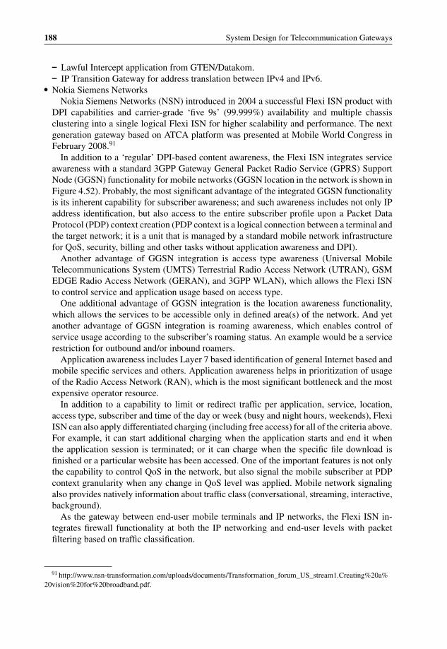
P1: OTA/XYZ P2: ABCc03 BLBK307-Bachmutsky September 2, 2010 13:12 Printer Name: Yet to Come
188 System Design for Telecommunication Gateways
– Lawful Intercept application from GTEN/Datakom.– IP Transition Gateway for address translation between IPv4 and IPv6.
� Nokia Siemens NetworksNokia Siemens Networks (NSN) introduced in 2004 a successful Flexi ISN product with
DPI capabilities and carrier-grade ‘five 9s’ (99.999%) availability and multiple chassisclustering into a single logical Flexi ISN for higher scalability and performance. The nextgeneration gateway based on ATCA platform was presented at Mobile World Congress inFebruary 2008.91
In addition to a ‘regular’ DPI-based content awareness, the Flexi ISN integrates serviceawareness with a standard 3GPP Gateway General Packet Radio Service (GPRS) SupportNode (GGSN) functionality for mobile networks (GGSN location in the network is shown inFigure 4.52). Probably, the most significant advantage of the integrated GGSN functionalityis its inherent capability for subscriber awareness; and such awareness includes not only IPaddress identification, but also access to the entire subscriber profile upon a Packet DataProtocol (PDP) context creation (PDP context is a logical connection between a terminal andthe target network; it is a unit that is managed by a standard mobile network infrastructurefor QoS, security, billing and other tasks without application awareness and DPI).
Another advantage of GGSN integration is access type awareness (Universal MobileTelecommunications System (UMTS) Terrestrial Radio Access Network (UTRAN), GSMEDGE Radio Access Network (GERAN), and 3GPP WLAN), which allows the Flexi ISNto control service and application usage based on access type.
One additional advantage of GGSN integration is the location awareness functionality,which allows the services to be accessible only in defined area(s) of the network. And yetanother advantage of GGSN integration is roaming awareness, which enables control ofservice usage according to the subscriber’s roaming status. An example would be a servicerestriction for outbound and/or inbound roamers.
Application awareness includes Layer 7 based identification of general Internet based andmobile specific services and others. Application awareness helps in prioritization of usageof the Radio Access Network (RAN), which is the most significant bottleneck and the mostexpensive operator resource.
In addition to a capability to limit or redirect traffic per application, service, location,access type, subscriber and time of the day or week (busy and night hours, weekends), FlexiISN can also apply differentiated charging (including free access) for all of the criteria above.For example, it can start additional charging when the application starts and end it whenthe application session is terminated; or it can charge when the specific file download isfinished or a particular website has been accessed. One of the important features is not onlythe capability to control QoS in the network, but also signal the mobile subscriber at PDPcontext granularity when any change in QoS level was applied. Mobile network signalingalso provides natively information about traffic class (conversational, streaming, interactive,background).
As the gateway between end-user mobile terminals and IP networks, the Flexi ISN in-tegrates firewall functionality at both the IP networking and end-user levels with packetfiltering based on traffic classification.
91 http://www.nsn-transformation.com/uploads/documents/Transformation_forum_US_stream1.Creating%20a%20vision%20for%20broadband.pdf.
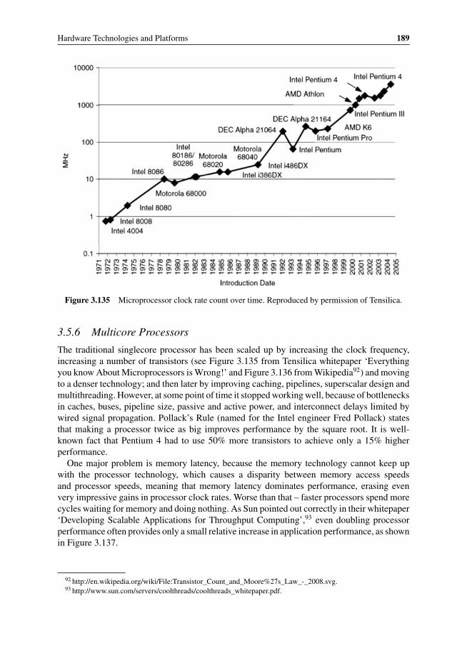
P1: OTA/XYZ P2: ABCc03 BLBK307-Bachmutsky September 2, 2010 13:12 Printer Name: Yet to Come
Hardware Technologies and Platforms 189
Figure 3.135 Microprocessor clock rate count over time. Reproduced by permission of Tensilica.
3.5.6 Multicore Processors
The traditional singlecore processor has been scaled up by increasing the clock frequency,increasing a number of transistors (see Figure 3.135 from Tensilica whitepaper ‘Everythingyou know About Microprocessors is Wrong!’ and Figure 3.136 from Wikipedia92) and movingto a denser technology; and then later by improving caching, pipelines, superscalar design andmultithreading. However, at some point of time it stopped working well, because of bottlenecksin caches, buses, pipeline size, passive and active power, and interconnect delays limited bywired signal propagation. Pollack’s Rule (named for the Intel engineer Fred Pollack) statesthat making a processor twice as big improves performance by the square root. It is well-known fact that Pentium 4 had to use 50% more transistors to achieve only a 15% higherperformance.
One major problem is memory latency, because the memory technology cannot keep upwith the processor technology, which causes a disparity between memory access speedsand processor speeds, meaning that memory latency dominates performance, erasing evenvery impressive gains in processor clock rates. Worse than that – faster processors spend morecycles waiting for memory and doing nothing. As Sun pointed out correctly in their whitepaper‘Developing Scalable Applications for Throughput Computing’,93 even doubling processorperformance often provides only a small relative increase in application performance, as shownin Figure 3.137.
92 http://en.wikipedia.org/wiki/File:Transistor_Count_and_Moore%27s_Law_-_2008.svg.93 http://www.sun.com/servers/coolthreads/coolthreads_whitepaper.pdf.
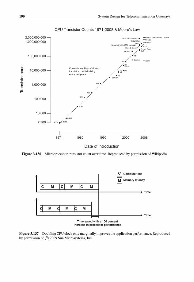
P1: OTA/XYZ P2: ABCc03 BLBK307-Bachmutsky September 2, 2010 13:12 Printer Name: Yet to Come
190 System Design for Telecommunication Gateways
Figure 3.136 Microprocessor transistor count over time. Reproduced by permission of Wikipedia.
C C
C M M M
M M MC
C C
C
M
Compute time
Memory latency
Time
Time
Time saved with a 100 percent increase in processor performance
Figure 3.137 Doubling CPU clock only marginally improves the application performance. Reproducedby permission of © 2009 Sun Microsystems, Inc.

P1: OTA/XYZ P2: ABCc03 BLBK307-Bachmutsky September 2, 2010 13:12 Printer Name: Yet to Come
Hardware Technologies and Platforms 191
C M M MC C
C
M
Compute time
Memory latency
Time
C M M MC C
C M M MC C
C M M MC C
Figure 3.138 More efficient CPU time usage with parallel computing cores or threads. Reproduced bypermission of © 2009 Sun Microsystems, Inc.
This is why practically all processor vendors decided to attack the problem from a differentdirection, parallelization. The first step can be software parallelization with better parallelalgorithms, software multi-threading and multi-processing, but even partial success in softwareparallelization brings with it quickly the need for hardware parallelization. The first step isinternal parallelization within the same core. The next step is to create a processor with multiplehardware cores or threads in order to improve system performance (see Figure 3.138).
In the beginning these multiple cores were just loosely coupled by using a single packagewith multiple dies, but the cores quickly became integrated tightly into a single die with muchhigher throughput and much lower latency of communication between cores. Today, CaviumNetworks and even more Tilera and Plurality are calling for a massive singlethreaded multicorewith many smaller and ‘simpler’ cores.
Another step towards success came when with improved software parallelism and the AMPmodel (see Section 4.3.7) performance became linearly scalable for at least some applications:N cores have close to Nx performance compared to a single core.
Multicore design also enabled the reduction of the power requirements of the processor.This concept is derived from the well-known fact that power consumption is non-linear withfrequency and a general rule-of-thumb can be that an increase of frequency by roughly 30%doubles the power. A dual-core processor running with 2 GHz clock frequency will consumeless power than a single 3 GHz core and will provide higher performance for well-parallelizedapplications, because it has a total of 4 GHz processing capacity.
Based on all of the multicore advantages and the fact that a single core power cap is reachedwithout having any other viable alternative, at least in the short term, it is forecast by someanalysts that by 2010 nearly 100% of processors shipped will be multicore. Others are a littlemore conservative. For example, based on the Venture Development Corp. study presented atthe Multicore Expo, embedded multicore CPU systems are expected to grow from $372 millionin 2007 to almost $2.5 billion in 2011. Also, in the 24 months since the report, embeddedmulticore adoption is expected to increase to nearly 79%. It may be not critical whether itis 79% or 100%, multicore designs are penetrating the next generation products at a veryfast pace.
However, a multicore design has some bottlenecks. One of them is memory throughput.To overcome this problem, high-end designs applied the same strategy as with multicoreby replicating the memory interfaces and integrating memory controllers on-chip. It is notunusual to see two and even four memory controllers, but the next bottleneck is the totalnumber of pins required for memory connection because of package size limitations and

P1: OTA/XYZ P2: ABCc03 BLBK307-Bachmutsky September 2, 2010 13:12 Printer Name: Yet to Come
192 System Design for Telecommunication Gateways
routing issues. There have been various attempts to find the solution for this problem andthe two most popular competing technologies are fully buffered FB-DIMM and XDR withserial interface that enables the reduction of the number of pins per memory controller andsupports many memory modules to be used per every interface; but they are more expensive.FB-DIMM places a buffer between the memory controller and the DDR2 memory modules,which increases size, complexity, power and cost.
Another way to ease the memory throughput problem is through smarter cache usage. Forexample, in one implementation the hardware checks whether the incoming packet can beserved immediately by one of the cores or threads; and if the processor is available, the packetis delivered directly to the cache, bypassing the memory entirely. In other implementationsa portion of the packet with headers is delivered into the cache, not accessing the externalmemory when processing only packet headers. The capability of using the cache as a localdata scratchpad can also decrease the need to go to the external memory.
Another bottleneck for increasing the number of cores is the cores’ interconnect technology.Without architectural changes, there is a quadratic dependence on the number of cores, so eightcores need a 36x communication channels compared to a single core, which grows to 32000xfor 256 cores. Legacy buses (that usually scale up to four to eight cores) and rings (that scale inmost cases up to sixteen cores) are already replaced in a number of high-end implementationsby internal switches, but some estimate that it will be difficult to scale these switches beyonda certain level. Depending on which opinion is subscribed to, that scalability is somewherebetween thirty-two to 128 cores. Some manycore processors (a new term for processorswith many tens of cores and higher) have decided to move from a single central switch toeither a ring, or a switch matrix (see, for example, the Tilera design in Section 3.5.6.2). Amore scalable internal interconnect might become a critical factor in the near future if certainpredictions about multicore and manycore processors come true. For example, Anant Agarwal,the founder and CTO of Tilera Corp., in his speech at a session on multicore design at the2007 International Solid-State Circuits Conference in San Francisco, California, estimatedthat by 2017 embedded processors could include up to 4096 cores, server processors will beimplemented with 512 cores and even desktop processors will reach 128 cores per chip. SunMicrosystems’ representative was less aggressive, but still predicted servers with thirty-twoto 128 cores by 2018.
At the same time, it is important to remember that the goal of multicore and multithreadingdesigns is to maximize overall system throughput, not necessarily the performance of a singleexecution instance (core or thread). As a result, the performance of a single software threadmay actually be lower than if it ran on a singlecore and singlethreaded processor. First of all, inmany implementations, the pipeline of a multicore and/or multithreaded processor is simpler,which affects performance immediately. Second, because cores or threads usually share someresources, an individual task may ultimately take more processor cycles to complete if theinterface to a shared resource or the performance of a shared resource becomes a bottleneck.This effect can be positive or negative:
� If a thread is stalled waiting for memory, its cycles can be used directly and immediately toprocess other threads that are ready to run.
� If many threads or cores are running the same application (a common occurrence in today’sdeployments), they can actually benefit from constructive sharing of text and data in the

P1: OTA/XYZ P2: ABCc03 BLBK307-Bachmutsky September 2, 2010 13:12 Printer Name: Yet to Come
Hardware Technologies and Platforms 193
Level-2 cache. On the other hand, synchronization between threads to access the sharedresource could reduce overall performance significantly.
� If one thread or core is thrashing or overusing a cache or other shared resource, other threadson that core can be affected adversely.
Before diving into the multicore processors discussion, it is useful to recall a highly success-ful multicore predecessor, the communications processor. Created by Freescale Semiconductormany years ago, the idea of the PowerQuicc communication processor was to combine a gen-eral purpose CPU with specialized data plane processing engines. The beauty of that designwas that data engines are programmable through the firmware update, and thus adaptable topractically any protocol. However, as Linley Gwennap, a founder and principal analyst forThe Linley Group, has described in his article ‘Communications Breakdown’ in the ElectronicEngineering Times’ 15 September 2008 issue, these data plane engines could not keep upwith a rapid increase in data rates. Also, some processing (stable protocols that do not needa flexibility of modification, especially MAC layer, and recently also networking IP layer)has been shifted into dedicated HW blocks. An additional disadvantage of the communicationprocessor is the lack of readily available development and debugging tools, allowing systemintegrators to develop the handling of their own proprietary or product-specific protocols.
In the article above, the author discusses the market’s expectation of a rapid drop in the sizeof the market for communication processors and a huge jump in sales of multicore processors.However, the idea of communication processors did not die; it is very much alive today and willlive on in new products. We expect that future multicore chips will include fully programmable(today they are mostly in fixed HW logic) classification engines performing at least partialpacket processing similar to the data engines described above.
It is worth remembering that a successful IBM Cell processor (the main processing engineof the highly popular Sony PlayStation 3, see below for more information) is built based ona similar communication processor concept, but for a different purpose, video processing andgaming. Some of the seeds of PowerQuicc principles are to be found in other heterogeneousmulticore solutions where not all of the cores are made identical. Such solutions can achievepotentially better performance for particular applications, but they are less flexible in thesupport of multiple concurrent applications sharing the same chip. Different cores may havepartially or totally different instruction set architectures, different development tools, languagesand libraries, optimization and debugging. Many heterogeneous solutions are driven by thedesktop market (for example, NVIDIA’s GeForce and AMD Fusion combine general purposeCPU with GPU cores). Some NPUs also include general purpose CPU combined with specialNPU engines (again, similar to the communication processor design). Mobile and handhelddevices can benefit from heterogeneous chips because of their higher power efficiency.
The topic of heterogeneous vs. homogeneous processors was one of the items discussedat the abovementioned 2007 International Solid-State Circuits Conference in San Francisco,California. Tilera predicted huge homogeneous processors, while Chuck Moore from AMDand Atsushi Hasegawa from Renesas Technology (to be merged with NEC Electronics Corp.in 2010) were leaning more towards heterogeneous implementations. Brad McCredie, a chiefmicroprocessor engineer at IBM, positioned himself somewhere in the middle (while stillleaning toward the heterogeneous designs) by predicting that future multicore architectureswill have a few specialized cores and many general purpose cores.

P1: OTA/XYZ P2: ABCc03 BLBK307-Bachmutsky September 2, 2010 13:12 Printer Name: Yet to Come
194 System Design for Telecommunication Gateways
On the other hand, multicore CPUs brought a critical functionality with them by imple-menting a core that is capable of processing both data and control plane tasks and multiplyingthe same core as many times as current chip manufacturing technology allows, with nearlylinear data plane processing performance scaling with a number of cores, while at the sametime being capable of running a full SMP system on some or all of the cores for control planeapplications. This enabled assigning cores (statically at boot time or dynamically at run time)to any application enabling the same hardware to be deployed in different networks with adifferent ratio between data and control plane load. Of course, an extremely important addi-tional benefit of multicore solutions is the availability of highly popular tools, programminglanguages and operating systems. Not to forget that these cores are increasingly adding specialinstructions (vector, hash, CRC calculation, checksum calculation, lookup, cryptography, etc.)for data plane packet processing in addition to a base instruction set (Power, ARM, MIPS,UltraSparc, x86), well known for its fit for control plane applications.
One of the biggest problems for multicore implementations is software support. Of course,distribution of tool readiness is not uniform between vendors. For example, companies likeSun, Cavium Networks, NetLogic and a few others are ahead of the curve not only in hardware,but also in software.
3.5.6.1 Multicore Architectures
There are a number of major multicore architectures: Symmetric Multiprocessing (SMP),Single Instruction Multiple Data (SIMD) and Massively Parallel Processor Arrays (MPPA).A good summary of SMP, SIMD and MPPA was provided by Mike Butts, then of Ambric(acquired by Nethra Imaging, Inc. in 2009), in his paper ‘Multicore and Massively ParallelPlatforms and Moore’s Law Scalability’ presented at the Embedded Systems Conference inSilicon Valley in 2008.
In SMP architecture, each processor is connected to shared memories for instructionsand data access; in many implementations these memories are also used for inter-processorcommunication. Each SMP processor normally has its own single- or multi-layer cache (forexample, the L1 cache is shared between hardware threads of the same core, the L2 cacheis shared between a number of cores and the L3 cache is shared between all of the coresin the system), with caches either dedicated to a particular processor or shared between asubset or all of the processors in the system. The processors communicate using some kindof interconnect technology (bus, ring, crossbar and/or packet switch matrix), as shown in theexample in Figure 3.139.
Each of these interconnect technologies has its advantages and disadvantages. Bus inter-connect is simple and efficient, but it is not very scalable and cannot be used for connectivitybetween a large number of nodes. To solve this problem, many designs subdivide the inter-connect into multiple bus domains, each with a potentially different width and speed, enablingscalability, functional optimization and more efficient power management.
Another option is the ring approach, which involves a high speed bus that chains all of theon-chip nodes together to form a large ring. Only adjacent nodes are connected in a point-to-point manner. Overall bandwidth allocation is controlled by setting up the appropriate amountof credit that each node has. A node can transfer a certain amount of data based on how muchcredit it holds currently and whether the bus is already occupied. If a node can transfer thedata, the amount of credit it holds is decreased in proportion to the amount of data transferred.

P1: OTA/XYZ P2: ABCc03 BLBK307-Bachmutsky September 2, 2010 13:12 Printer Name: Yet to Come
Hardware Technologies and Platforms 195
Figure 3.139 SMP interconnect technologies. Reproduced by Nethra Imaging Inc.
If a node cannot transfer the data, it waits for the next turn and gets back some credit up to thepre-set maximum value for this unit. The ring approach achieves a certain level of worst casebehavior predictability when the communication load is not very heavy, but it has also a fewdisadvantages:
� Data transfer between two nodes on the ring can incur high latency when there are manyother nodes between them or when the bus is used heavily.
� Data transfer between two nodes on the ring can incur highly non-deterministic latency,depending on how heavily loaded the bus is, and the sources and destinations of the othertransfers that the ring is carrying at the same time. Moreover, as the number of nodes on thering increases, the non-deterministic nature of the transfer latency worsens quickly.
� The ring topology provisions the same amount of bandwidth frequently between all adjacentnodes along the whole ring. Moreover, data movement only occurs along the ring. The net

P1: OTA/XYZ P2: ABCc03 BLBK307-Bachmutsky September 2, 2010 13:12 Printer Name: Yet to Come
196 System Design for Telecommunication Gateways
effect is that data have to travel longer distance than necessary and bandwidth becomes over-provisioned for some types of data transfers or along some sections of the ring. As a resultof these inefficiencies, the ring approach might consume more power if not implementedcarefully.
� The ring approach usually relies on the ring to transfer both control messages and data.For example, when a CPU core needs to request a cache line fill, it has to send a controlmessage on the ring from this core to the shared cache controller or memory controller. If anynode can only send one thing during each time slot, the CPU core in this example cannotwrite back any data to the cache or memory in parallel during the same time slot. Again, insome implementations it can affect the performance.
However, many vendors still choose the ring for core interconnect. In some cases multiplerings are deployed, or heterogeneous rings are implemented (the throughput of different ringsegments could be different depending on bottlenecks in the system), or bi-directional ringsare used to manage better a number of hops between communication nodes on the ring and toimprove the latency and throughput of data transfers.
A crossbar interconnect enables direct point-to-point communication between any twonodes. It is potentially the best performing interconnect, but its major drawback is increasedcomplexity with an increasing number of nodes. Figure 3.139(c) illustrates this complexityclearly.
A central multi-port switch (not shown in Figure 3.139) can minimize the amount of point-to-point connections; however, a high-performance non-blocking switch with a large numberof ports becomes large and expensive.
The packet switch matrix (implemented, for example, by Tilera, see Section 3.5.6.2.11)is an efficient approach for a large number of nodes; in many implementations every switchis very deterministic in terms of latency, but even in such a case overall end-to-end latencybetween nodes varies depending on their location. For example, the left bottom CPU in Figure3.139(d) will have significantly lower I/O access latency compared to the right top CPU.Therefore, the architecture is good for latency insensitive applications or in scenarios wheresystem functionality can be spread between CPUs in a way that takes into account differentlatencies to access peripherals or other CPUs. In addition, packet switch matrix requires allnon-blocking switches and careful throughput considerations on all links to avoid congestion,which would be especially critical for frequently accessed nodes, like I/O or memories. On theother hand, Tilera proved that this type of interconnect can be implemented successfully andit is probably the most promising and most scalable inter-core communication in manycoreprocessors.
Of course, there are some hybrid implementations where multiple separate interconnects(for example, multiple shared buses or multiple rings) and interconnect types are used fordifferent communication paths at the same time. This enables different throughput and/orlatency for different interconnects, separation of data, control and management traffic withinthe chip and many other enhancements.
Most SMP-based systems have complex cache and cache coherency management. It allows,on the one hand, bringing the required code or data as close to the CPU core as possible in orderto minimize latency and on the other hand ensures that the modification of shared content isreplicated to other caches as and when needed. These management schemes include cache bussnoopers and single-level or hierarchical directories for operation checking across all caches.
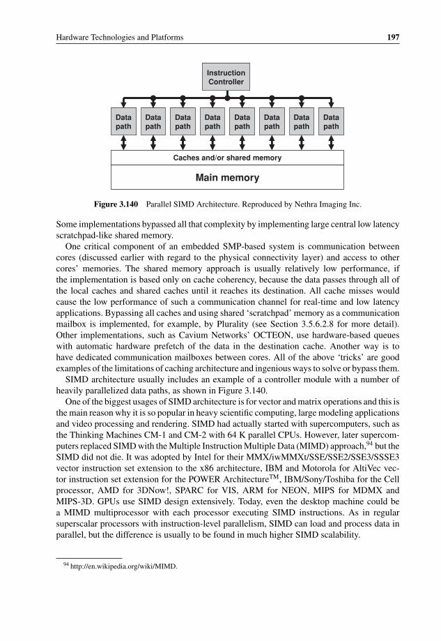
P1: OTA/XYZ P2: ABCc03 BLBK307-Bachmutsky September 2, 2010 13:12 Printer Name: Yet to Come
Hardware Technologies and Platforms 197
Instruction Controller
Datapath
Datapath
Datapath
Datapath
Datapath
Datapath
Datapath
Datapath
Caches and/or shared memory
Main memory
Figure 3.140 Parallel SIMD Architecture. Reproduced by Nethra Imaging Inc.
Some implementations bypassed all that complexity by implementing large central low latencyscratchpad-like shared memory.
One critical component of an embedded SMP-based system is communication betweencores (discussed earlier with regard to the physical connectivity layer) and access to othercores’ memories. The shared memory approach is usually relatively low performance, ifthe implementation is based only on cache coherency, because the data passes through all ofthe local caches and shared caches until it reaches its destination. All cache misses wouldcause the low performance of such a communication channel for real-time and low latencyapplications. Bypassing all caches and using shared ‘scratchpad’ memory as a communicationmailbox is implemented, for example, by Plurality (see Section 3.5.6.2.8 for more detail).Other implementations, such as Cavium Networks’ OCTEON, use hardware-based queueswith automatic hardware prefetch of the data in the destination cache. Another way is tohave dedicated communication mailboxes between cores. All of the above ‘tricks’ are goodexamples of the limitations of caching architecture and ingenious ways to solve or bypass them.
SIMD architecture usually includes an example of a controller module with a number ofheavily parallelized data paths, as shown in Figure 3.140.
One of the biggest usages of SIMD architecture is for vector and matrix operations and this isthe main reason why it is so popular in heavy scientific computing, large modeling applicationsand video processing and rendering. SIMD had actually started with supercomputers, such asthe Thinking Machines CM-1 and CM-2 with 64 K parallel CPUs. However, later supercom-puters replaced SIMD with the Multiple Instruction Multiple Data (MIMD) approach,94 but theSIMD did not die. It was adopted by Intel for their MMX/iwMMXt/SSE/SSE2/SSE3/SSSE3vector instruction set extension to the x86 architecture, IBM and Motorola for AltiVec vec-tor instruction set extension for the POWER ArchitectureTM, IBM/Sony/Toshiba for the Cellprocessor, AMD for 3DNow!, SPARC for VIS, ARM for NEON, MIPS for MDMX andMIPS-3D. GPUs use SIMD design extensively. Today, even the desktop machine could bea MIMD multiprocessor with each processor executing SIMD instructions. As in regularsuperscalar processors with instruction-level parallelism, SIMD can load and process data inparallel, but the difference is usually to be found in much higher SIMD scalability.
94 http://en.wikipedia.org/wiki/MIMD.

P1: OTA/XYZ P2: ABCc03 BLBK307-Bachmutsky September 2, 2010 13:12 Printer Name: Yet to Come
198 System Design for Telecommunication Gateways
CPU(s) RAM(s)
CPU(s) RAM(s)
CPU(s)RAM(s)
CPU(s)RAM(s)
CPU(s) RAM(s)
CPU(s) RAM(s)
CPU(s)RAM(s)
CPU(s)RAM(s)
CPU(s) RAM(s)
CPU(s) RAM(s)
CPU(s)RAM(s)
CPU(s)RAM(s)
switchbuses
Figure 3.141 MPPA Architecture. Reproduced by Nethra Imaging Inc.
MPPA is based on the MIMD distributed memory architecture, where each processor isusing strictly only its own code and memory using no cache and no virtualization techniqueswith the point-to-point dedicated unshared communication between processors performed viathe configurable interconnect, as shown in Figure 3.141.
To be able to integrate a large number of processing elements, simple RISC integer/fixed-point single-threaded CPUs are used. Similar to FPGAs, the word-wide communicationchannels between these processors are configured per application and its deployment in theprocessor array, but the channels are registered to avoid any issues related to timing closure.Some implementations of communications are unbuffered, where processors negotiate the datatransfer ahead of time. Others are buffered, meaning that the processor can fill the buffer andcontinue doing other jobs. Communication implementation is often simplified: assuming thatthe channel flow control is active, the sending processor will stall if the receiving processorcannot accept the data for any reason. Similarly, the receiving processor will stall performingreading instruction if there is no data available (see Figure 3.142).
One of the main advantages of MPPA from the programming point of view is its determinism:there is no shared memory anywhere in the system; communication channels are dedicatedto every pair of processing elements and cannot be accessed by any other entity; the timingis deterministic because of single threaded code and simple uncached real memory. Thisdeterministic behavior simplifies application debugging and an integration of sub-functionsand common libraries running on separate processors.
Processor
output synch: stall if
not accepting
Processor
input synch: stall if not valid
Channel
Figure 3.142 MPPA buffered flow-controlled communication channel. Reproduced by Nethra ImagingInc.

P1: OTA/XYZ P2: ABCc03 BLBK307-Bachmutsky September 2, 2010 13:12 Printer Name: Yet to Come
Hardware Technologies and Platforms 199
The great disadvantage of MPPA-based chips is the need to port every application writtenfor any other single- or hardware multithreaded processor. At the same time code size at everyprocessor is limited by the amount of its local memory and cannot be increased if needed.
One aspect of core architecture is instruction width. AMD has pushed for 64-bit processorswith their Opteron chips with the main target for these chips being the server market withconfigurations requiring a large amount of memory, beyond what can be done efficiently with32-bit processors. In the embedded world there are few applications that would justify so largea memory; therefore, the embedded market did not really push for 64-bit processors, at leastnot because of the size of memory. In addition, a 32-bit environment has implemented memorypaging enabling the addressing of larger memory by switching memory banks. The scheme hasa performance penalty, but if it is not performed frequently, it can be an acceptable solution.
64-bit processors enable more precise arithmetical calculations. AMD argued in one oftheir whitepapers that 32-bit processors cannot even store the US national debt figure, andthat with their 64-bit processors our debt can continue to grow with the same pace as todayfor next 300 years and will still be represented correctly by their processor. On a humorousnote, if the US national debt will grow with current rate for much less than 300 years,AMD would potentially not exist. More seriously, similar to the previous comment, not alltelecom applications require 64-bit arithmetic and the focus in this book is not on server, buttelecommunication applications.
Another argument is that most 64-bit processors run natively 32-bit applications withoutany impact on performance. This is correct, but every feature takes up some chip area and thatarea is very expensive. All that said, the trend is still toward the 64-bit cores. Examples ofthe trend include non-server products, such as the Cavium Networks OCTEON or NetLogic’sXLR/XLP, which are based on MIPS64 architecture.
3.5.6.1.1 Multithreading ArchitecturesSometimes a CPU has to wait until either memory access is finished, or cache is filled, orpipeline is filled, etc. This becomes especially critical for high-end systems because of thehigh CPU operating frequency and the high price for not doing anything even during relativelyshort periods of time. This is where multithreading comes to help. Multithreading is basedon the principle that if a single program is not capable of fully using all CPU resources,the processor can share these resources between multiple concurrent threads of execution.Every single program would not run faster in the multithreaded environment, but two parallelprograms would run significantly faster than double the single program run time. If the secondprogram also needs to wait for some resource while the first program is running at the sametime, the third thread would bring additional benefit in running three programs concurrently.The same logic is applicable to any number of N parallel programs using M threads.
There are various ways to implement multithreading. Interleaved multithreading switchesthread on every instruction to achieve Thread Level Parallelism (TLP); it is sometimes calledfine-grain multithreading. Static interleaving allocates its own time slot for every threadcausing significant performance limitation when only a single application has to run. Dynamicinterleaving enables more flexible time slot allocation, but is significantly more complexto implement efficiently. Blocked multithreading (also called coarse-grain multithreading)performs switching only when the currently running program hits the wait state (blocked) forany reason; it is easier to implement, but some programs can be starved if one of them doesnot have any blocking event for a long period of time. It might sound counterintuitive, but

P1: OTA/XYZ P2: ABCc03 BLBK307-Bachmutsky September 2, 2010 13:12 Printer Name: Yet to Come
200 System Design for Telecommunication Gateways
with blocked multithreading it might be better to have blocking events relatively frequently ifmultiple concurrent programs compete for the CPU. There are also implementations of hybridmultithreading that combine blocked model with static or dynamic interleaving.
The most complex for implementation is simultaneous multithreading (SMT) on superscalarprocessors which was developed by IBM back in 1968 and implemented commercially byDEC (all intellectual property was sold to Intel through Compaq in 2001) and Intel (whichappeared first in Pentium 4 in 2002 and is called Hyper-Threading Technology (HTT)) with thehelp of Dean Tullsen of the University of California, San Diego and Susan Eggers and HankLevy of the University of Washington. SMT enables issuing multiple concurrent instructions(in practice, most implementations have only two because of high complexity) from differentthreads at a given pipeline stage providing Instruction Level Parallelism (ILP); if only a singleinstruction is allowed to be executed at any point of time, it is called temporal multithreading.
For example, Sun UltraSPARC T1 (codenamed Niagara) is a multicore processor witha single pipeline and a fine-grain multithreading (the next running thread is selected usinground-robin algorithm) with each core able to issue only one instruction at a time. The SunUltraSPARC T2 is more complex, implementing two integer execution pipelines, one floating-point execution pipeline and one memory pipeline. The floating-point and memory pipelinesare shared by all eight threads, meaning that at any given time only two threads are workingphysically in parallel issuing either a pair of integer pipeline operations, an integer operationand a floating-point operation, an integer operation and a memory operation, or a floating-pointoperation and a memory operation. More information about Sun UltraSPARC processors canbe found in Section 3.5.6.2.9.
Intel had removed HTT in their Core Architecture (devices like Celeron M, Core 2Solo/Duo/Quad/Extreme, dual-core and quad-core Xeon), but re-introduced it again in theNehalem microarchitecture. Intel had implemented HTT in the newest Atom processor, but tosimplify the core the Atom does not support instruction reordering, speculative execution, orregister renaming.
IBM’s POWER5 has dual-threaded SMT core in dual-, quad, or eight-core configurations.Different threads can be assigned priorities and an SMT engine can be turned on and offdynamically in scenarios where SMT is not efficient, which is a very good addition.
MIPS architecture also includes SMT called MIPS MT . Simpler implementations can incor-porate lighter ‘microthreading’, the more complex can use Virtual Processing Element (VPE),supported by instruction set extensions. As described by Kevin D. Kissel, principal architect,and Pete Del Vecchio, product marketing manager, both at MIPS Technologies, in their article‘Get Multicore Performance from One Core’ in the April 2007 issue of Embedded SystemsDesign magazine,95 each thread has its own dedicated hardware called Thread Context (TC)with a per-thread instruction buffer with pre-fetching, per-thread general purpose registers andprogram counters. Some resources, especially CP0 registers used by the privileged code inthe OS kernel, are shared between threads; these registers together with TCs make VPE. Allthreads share the same cache for easier cache coherency. Cores can use up to nine TCs across amaximum of two VPEs; that combination of TCs and VPEs enables area-efficient and flexiblesolution. For example, a data or control plane can run on a VPE. VPE parallelism is similar toSMP parallelism, and existing SMP-based OS can easily be adapted to run on VPEs in VirtualSMP (VSMP), but the HW implementation is heavier. Thread parallelism is based on explicitcontrol; it allows very low overhead thread creation and deletion, but requires modified OS,
95 http://www.ddj.com/architect/199100437.

P1: OTA/XYZ P2: ABCc03 BLBK307-Bachmutsky September 2, 2010 13:12 Printer Name: Yet to Come
Hardware Technologies and Platforms 201
libraries and compilers, while having much smaller hardware support enabling more TCs pergiven chip area. MIPS architecture includes a QoS engine that picks by means of the DispatchScheduler the next thread on every cycle using a weighted round robin algorithm (TCs can beconfigured with their processing bandwidth and the integrated Policy Manager monitors allTCs constantly), for example, to differentiate between ‘background’ control and managementplanes and real-time tasks for data plane processing with even finer granularity of networking,audio or video processing.
Together with many advantages, multithreading carries the following disadvantages oroverhead:
� Multithreading reduces the effective cache capacity that each thread can utilize, because thethreads in the same processor core share and compete with each other in the same L1 cache.As a result, multithreading causes either more cache thrashing, or smaller per-thread cachecapacity, or both.
� Multithreading worsens the cache hit rate and results in more cache misses. Each cache missmeans another cache line fill and access to memory. So, while multithreading attempts tohide memory latencies, it increases the frequency of memory accesses. Each memory accessincurs latency and impacts on performance.
� The number of threads in each processor core is limited and the processor core still stallswhen all of the threads are waiting for memory accesses. As such, multithreading requirescareful performance tuning of the program execution sequence, in order to hide latencysuccessfully and to realize the expected performance gain. In addition, multithreading leadsto low cache hit predictability, which complicates the performance tuning effort significantly.This problem, however, can be addressed by more sophisticated tools.
� Multithreading involves greater software complexity, because uncoordinated operations onshared data can result in functional errors. Instead, software locking mechanisms can beimplemented, again affecting complexity and performance. This problem is common, ofcourse, with multicore processors in general.
� Multithreading incurs additional complexity of hardware implementation. Implementationcomplexity translates into cost which is reflected typically in power consumption and siliconarea.
� When Intel introduced HTT in Pentium 4, this feature was claimed to improve perfor-mance by about only 30%. However, even then it was clear that its impact is very muchapplication-dependent; in some cases performance is actually decreased because of addi-tional contention for shared resources, especially bus and memory bandwidth, caches, TLBs,etc. The claim was that such applications with decreased performance can be optimized foran HTT environment and enjoy a performance boost after that.
It is important to mention that in some special implementations multithreading can helpeven with single-threaded applications. For example, interrupt handling involves a ‘temporary’jump in the interrupt processing code and a return to the original place after the end of theinterrupt. In a single threaded core such an action would reload caches and pipeline, saveregisters in software and so on. A multithreaded core can run the interrupt processing in thesecond thread performing everything above in hardware and keeping caches (and pipeline ifmultiple pipelines are implemented) intact.
Another example of use of hardware multithreading is for redundancy: it is possible torun a redundant or standby module in a second thread (preferable with virtualization for full

P1: OTA/XYZ P2: ABCc03 BLBK307-Bachmutsky September 2, 2010 13:12 Printer Name: Yet to Come
202 System Design for Telecommunication Gateways
memory protection) with hot standby protection against software failures and significantlylower impact on the CPU load.
With all that in mind, it is important to remember that a multithreaded core is larger thana singlethreaded one with all other parameters equal, meaning that the same chip area caninclude more singlethreaded cores than multithreaded. For example, Cavium Networks wasable to place thirty-two single-threaded MIPS64 cores, while NetLogic placed only eightquad-threaded cores (there is more information about these processors later in this chapter).In general, with all other parameters equal a core is always better than a thread. The problemis that it is usually not that simple and not all of the other parameters are equal. In theabove comparison Cavium Networks used 1.5 GHz cores without a floating point unit, whileNetLogic used 2.5 GHz cores with a floating point unit. Of course, there are even moredifferences with advantages and disadvantages on both sides.
The efficiency of multithreaded cores depends on the application. Heavy control planeapplications with large code and data spaces and a lot of memory accesses will benefit a greatdeal from multithreading. Small data plane applications running till completion in a tightloop with limited memory accesses will benefit less. Without making a better estimation fora particular application, experience shows that for data plane processing the 2nd thread addsabout 40% in performance, with the 3rd and 4th threads adding about 10% each, while threadsbeyond the 4th do not add significant performance benefits.
An important comparison parameter might be the need to run multiple operating systemson the same core, which is done using the hypervisor and virtual machines (see Section 4.4). Ifmultiple VMs share the same core, there is a need to have a scheduler at the hypervisor level inorder to schedule these VMs based on the required priority and other rules. Scheduling itselfand loading another VM into the CPU affects performance, frequently very significantly andis even critical for real-time systems because of registers, caches and other shared resources.It is possible to save some swapping overhead if all of the shared resources (for example,caches) are subdivided between VMs, but in such a scenario every VM would get a muchlower portion of these subdivided resources. Of course, having multiple hardware threads witha single VM per thread is better (with all other parameters equal) than running multiple VMson a singlethreaded core. However, running four VMs on four singlethreaded cores is better(again, with all other parameters equal) than running four VMs on a single quadthreadedcore. A similar principle should be considered even when comparing singlethreaded multicorearchitectures. From the VM switching point of view, it is always better to have as muchindependent resources per core as one can. For instance, while L1 cache is usually sharedbetween multiple threads of the same core, they are independent for every core. If we considerthe next level cache, L2, it is shared frequently between multiple cores, and for VM schedulingit is better that sharing be as limited as possible (if not dedicated per core, at least shared onlyby a subset of all cores), or in other words L2 cache size per execution thread is an importantparameter. The same is true for L3 cache, if it exists, and many other shared resources.
3.5.6.2 Commercial Multicore CPUs
This chapter describes multiple commercial multicore processors, each is different and poten-tially optimized for a different application. Some of these CPUs are designed mainly for servermarkets and adapted for telecommunication applications, others are designed specifically for
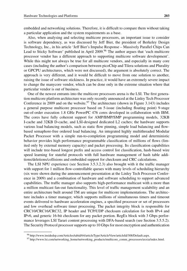
P1: OTA/XYZ P2: ABCc03 BLBK307-Bachmutsky September 2, 2010 13:12 Printer Name: Yet to Come
Hardware Technologies and Platforms 203
embedded and networking solutions. Therefore, it is difficult to compare them without takinga particular application and the system requirements as a base.
Also, when analysing and selecting multicore processors, an important issue to consideris software dependency, as was discussed by Jeff Bier, the president of Berkeley DesignTechnology, Inc., in his article ‘Jeff Bier’s Impulse Response – Massively Parallel Chips CanLead to Sticky Software’ published in April 2009.96 The author argues that ‘each multicoreprocessor vendor has a different approach to supporting multicore software development’.While this might not always be true for all multicore vendors, and especially in many corecases (including the author’s comparison between picoChip and Tilera solutions and Pluralityor GPCPU architectures, which were not discussed), the argument is absolutely correct. Theapproach is very different, and it would be difficult to move from one solution to another,raising the issue of software stickiness. In practice, it would have an extremely severe impactto change the manycore vendor, which can be done only in the extreme situation where thatparticular vendor is out of business.
One of the newest entrants into the multicore processors arena is the LSI. The first genera-tion multicore platform architecture was only recently announced at the Linley Tech ProcessorConference in 2009 and on the website.97 The architecture (shown in Figure 3.143) includesa general purpose multicore processor based on 5-issue (including floating point) 9-stageout-of-order execution 1.8 GHz PowerPC 476 cores developed in collaboration with IBM.The cores have fully coherent support for AMP/BMP/SMP programming models, 32KBI-cache and 32KB D-cache, and LSI-designed dedicated L2 caches; the hardware supportsvarious load balancing models, such as static flow pinning, simple load balancing and flow-based semaphore-free ordered load balancing. An integrated highly multithreaded ModularPacket Processor with a simple run-to-completion programming model and deterministicbehavior provides high performance programmable classification of millions of flows (lim-ited only by external memory capacity) and packet processing. Its classification capabilitieswill include tree-based longest prefix and access control list classification, hash-based wirespeed learning for stateful protocols with full hardware management of hash table addi-tions/deletions/collisions and embedded support for checksum and CRC calculations.
The LSI NPU experience (see Section 3.5.3.2.3) also brought with it the traffic managerwith support for 1 million flow-controllable queues with many levels of scheduling hierarchy(six were shown during the announcement presentation at the Linley Tech Processor Confer-ence in 2009) and a combination of hardware and software scheduling to support advancedcapabilities. The traffic manager also supports high-performance multicast with a more thana million multicast fan-out functionality. This level of traffic management scalability and anentire architecture built around TM are unique for multicore implementations. The architec-ture includes a timer manager, which supports millions of simultaneous timers and timeoutevents delivered to hardware acceleration engines, a specified processor or set of processorsand low overhead software timer processing. The packet integrity block is responsible forCRC10/CRC16/CRC32, IP header and TCP/UDP checksum calculation for both IPv4 andIPv6, and generic 16-bit checksum for any packet portion. RegEx block with 3 Gbps perfor-mance leverages LSI Tarari content processing with DFA-based search (see Section 3.5.5.2).The Security Protocol processor supports up to 10 Gbps for most encryption and authentication
96 http://www.insidedsp.com/Articles/tabid/64/articleType/ArticleView/articleId/308/Default.aspx.97 http://www.lsi.com/networking_home/networking_products/multicore_comm_processors/axxia/index.html.

P1: OTA/XYZ P2: ABCc03 BLBK307-Bachmutsky September 2, 2010 13:12 Printer Name: Yet to Come
204 System Design for Telecommunication Gateways
Figure 3.143 LSI AxxiaTM Communication Processor (ACP) Block Diagram. Reproduced by permis-sion of LSI.
protocols, including Kasumi and SNOW3G for wireless applications. The LSI architecturecan also leverage another technology, Digital Signal Processing (DSP). It is based on the500 MHz StarCore SC3400 DSP family of cores with 32KB I-cache, 32KB D-cache,256KB local RAM, memory protection unit, programmable interrupt controller and dedicated2-channel DMA controller. This architecture looks very promising.
3.5.6.2.1 AMDThe focus of AMD products is on the desktop and server markets, not telecommunicationembedded space. However, they are also used in networking products and one example wouldbe the ATCA blade ATC6239 from Diversified Technology,98 incorporating two six-core2.1 GHz Istanbul AMD processors with up to 32 GB of memory, dual 10 Gigabit Ethernetswitch fabric interfaces and AMC expansion slot. At the same time, without taking awaygreat processing capabilities, we will not describe here Opteron processors, just as we do not
98 http://www.dtims.com/products/atca/atc6239.php.

P1: OTA/XYZ P2: ABCc03 BLBK307-Bachmutsky September 2, 2010 13:12 Printer Name: Yet to Come
Hardware Technologies and Platforms 205
describe ‘regular’ Intel processors. Instead, AMD virtualization and paging technologies arereviewed.
AMD has developed its proprietary virtualization acceleration technology, AMD-VTM, andworked with the key developers of x86 virtual machine environments, including VMware,Microsoft, and XenSource, to find the best offload solutions and ensure that their currentsoftware based virtualization technologies are certified for operation on AMD OpteronTM andAMD AthlonTM 64 platforms. AMD-V technology is a set of hardware extensions to the x86system architecture, designed to improve the efficiency and reduce the performance overheadof virtualization solutions. AMD-V reduces and sometimes eliminates the burden of trappingand emulating instructions executed within a guest operating system.
Three main features of AMD-V are the following:
� AMD-V Extended Migration – a hardware feature that helps virtualization software en-able live migration of virtual machines between all available AMD OpteronTM processorgenerations.
� Tagged TLB – Hardware features that facilitate efficient switching between VMs for betterapplication responsiveness.
� Rapid Virtualization Indexing – Helps accelerate the performance of many virtualized ap-plications by enabling hardware-based VM memory management. Rapid VirtualizationIndexing (RVI) allows virtual machines to manage memory directly utilizing hardwareresources rather than software resources. RVI can help reduce hypervisor cycles and theassociated performance penalty that is commonly associated with virtualization.
A better understanding of RVI benefits requires knowledge of basic address translation andpaging concepts. Paging is, in practice, per instruction and data access operation translation ofmemory addresses from virtual process-specific address (used to isolate processes from eachother) to real physical memory address. The first level of translation is done in the majorityof processors today, but virtualization can bring with it the need for an additional level ofmapping, because there is a need to perform mapping from the guest’s physical memory pointof view to the system physical memory’s point of view. This means that the hypervisor wouldbe responsible for virtualizing processor paging and the software implementations of thisvirtualization, such as shadow-paging, are expensive from the processing overhead angle. Thesoftware maintains a shadow version of the page table derived from the guest page table andthe hypervisor forces the processor to use the correct shadow page table (not visible to theguest) to perform address translation. To track page table modifications the hypervisor mayconfigure the guest page table to be read-only causing a page fault exception when anyonetries to modify it; page fault is processed by the hypervisor to emulate the required behavior.In another scheme called Virtual TLB, the exception is generated not when modifying theTLB entry, but when trying to access the memory referred by the entry; and from that pointon the processing is similar to that in the previous case. Both implementations are inefficientbecause of the large number of page fault exceptions to be processed. In addition, there are‘normal’ page faults unrelated to the virtualization that come to the hypervisor and have to beidentified as unrelated, which brings additional overhead. The problem is even worse in theSMP system, because the table should be kept per core/processor which either requires muchmore memory or in the case of shared memory uses some memory synchronization through,for example, undesirable semaphores.
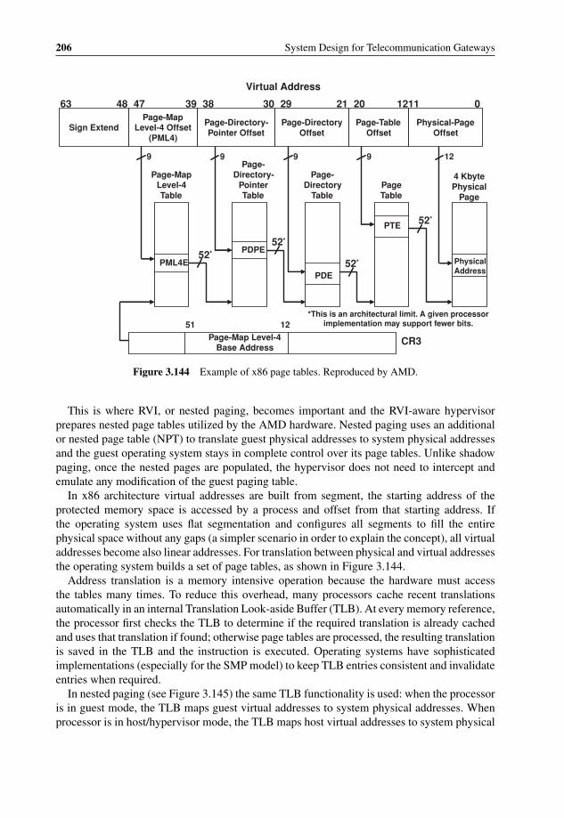
P1: OTA/XYZ P2: ABCc03 BLBK307-Bachmutsky September 2, 2010 13:12 Printer Name: Yet to Come
206 System Design for Telecommunication Gateways
Sign ExtendPage-Map
Level-4 Offset (PML4)
Page-Directory-Pointer Offset
Page-Directory Offset
Page-Table Offset
Physical-Page Offset
01211202129303839474863
Virtual Address
PML4E
PDPE
PDE
PTE
Physical Address
129999
52*
52*
52*
52*
Page-Map Level-4 Table
Page-Directory-
Pointer Table
Page-Directory
TablePage Table
4 Kbyte Physical
Page
*This is an architectural limit. A given processor implementation may support fewer bits.
Page-Map Level-4 Base Address
1251
CR3
Figure 3.144 Example of x86 page tables. Reproduced by AMD.
This is where RVI, or nested paging, becomes important and the RVI-aware hypervisorprepares nested page tables utilized by the AMD hardware. Nested paging uses an additionalor nested page table (NPT) to translate guest physical addresses to system physical addressesand the guest operating system stays in complete control over its page tables. Unlike shadowpaging, once the nested pages are populated, the hypervisor does not need to intercept andemulate any modification of the guest paging table.
In x86 architecture virtual addresses are built from segment, the starting address of theprotected memory space is accessed by a process and offset from that starting address. Ifthe operating system uses flat segmentation and configures all segments to fill the entirephysical space without any gaps (a simpler scenario in order to explain the concept), all virtualaddresses become also linear addresses. For translation between physical and virtual addressesthe operating system builds a set of page tables, as shown in Figure 3.144.
Address translation is a memory intensive operation because the hardware must accessthe tables many times. To reduce this overhead, many processors cache recent translationsautomatically in an internal Translation Look-aside Buffer (TLB). At every memory reference,the processor first checks the TLB to determine if the required translation is already cachedand uses that translation if found; otherwise page tables are processed, the resulting translationis saved in the TLB and the instruction is executed. Operating systems have sophisticatedimplementations (especially for the SMP model) to keep TLB entries consistent and invalidateentries when required.
In nested paging (see Figure 3.145) the same TLB functionality is used: when the processoris in guest mode, the TLB maps guest virtual addresses to system physical addresses. Whenprocessor is in host/hypervisor mode, the TLB maps host virtual addresses to system physical

P1: OTA/XYZ P2: ABCc03 BLBK307-Bachmutsky September 2, 2010 13:12 Printer Name: Yet to Come
Hardware Technologies and Platforms 207
PML4 Offset PDP Offset PD Offset PT Offset Physical-Page Offset
01211202129303839474863
gPML4E
gPDPE gPDE
gPTE
gData
Page-Map Level-4 Table
Page-Directory-Pointer Table
Page-Directory Table
Page Table
Guest 4KB Memory Page
Nested walk
Nested walk
Nested walk
Nested walk
Nested walk
gCR3
1251
Guest Virtual
4K pages
addressed by guest physical
addressGu
est
pag
e ta
ble
s
PML4 Offset PDP Offset PD Offset PT Offset Physical-Page Offset
01211202129303839474863
nPML4E
nPDPE nPDE
nPTE
Page-Map Level-4 Table
Page-Directory-Pointer Table
Page-Directory Table
Page Table
Guest 4KB Memory Page
nCR3
1251
4K pages
addressed by system physical
addressNes
ted
pag
e ta
ble
s
gPML4E
Nested walk
Figure 3.145 Example of AMD nested page tables. Reproduced by AMD.
addresses. Nested paging is cached by AMD processors in the nested TLB similar to theregular TLB.
A hypervisor using nested paging can set up a single instance of the nested paging tableto map the entire guest physical address space. It should typically consume considerablyless memory than an equivalent shadow-paging implementation. It also helps in SMP mode,because there is no need for a per-processor copy of the table or expensive synchronization ofmultiple copies. In addition, internal hardware caches for guest and nested page walk improveperformance significantly.
It is obvious that TLB size is one of critical parameters of the processor; and bigger isbetter. AMD Barcelona processors, for example, keep up to forty-eight TLB entries of anypage size in L1 cache, and 512 TLB entries of 4 KB pages or 128 TLB entries of 2 millionpages in L2 cache. In addition, the TLB table can be partitioned between guests, and AMDuses Address Space IDs that are assigned to every guest operating system and kept as a part ofevery TLB entry; it reduces the need to flush the TLB for every guest/VM switch. Of course,TLB partitioning reduces the amount of TLB entries available for every guest; with multiplevirtual machines and full TLB partitioning there might be only a few TLB entries per VM inL1 cache.
Initial performance measurements run by AMD were very encouraging, bringing for someapplications almost 100% additional improvement with nested paging turned on.

P1: OTA/XYZ P2: ABCc03 BLBK307-Bachmutsky September 2, 2010 13:12 Printer Name: Yet to Come
208 System Design for Telecommunication Gateways
General Purpose Communication Processor
NPU Data Path Processor
CPU Core
CPU Core
NPU Core
NPU Core
NPU Core
NPU Core
DMAGPIO Memory
Network Interface
High Speed
Interface
Memory
Memory
Buffer Mgr
TM Schdlr
Network Interfaces
A highly programmable processor with flexible communications paths that can effectively embrace both compute and data flow intensive applications
• Industry-standard Processor Architecture? PowerPC
• w/ high per thread performance and low power• Multicore – performance and functional partitioning• A balanced memory system• Accelerators• Efficient and flexible intra and inter processor communications• End to End Quality of Service w/Over subscription support
General Purpose Communication Processor
NPU Data Path Processor
CPU Core
CPU Core
NPU Core
NPU Core
NPU Core
NPU Core
DMAGPIO Memory
Network Interface
High Speed
Interface
Memory
Memory
Buffer Mgr
TM Schdlr
Network Interfaces
A highly programmable processor with flexible communications paths that can effectively embrace both compute and data flow intensive applications
• Industry-standard Processor ArchitecturePowerPC
• w/ high per thread performance and low power• Multicore – performance and functional partitioning• A balanced memory system• Accelerators• Efficient and flexible intra and inter processor communications• End to End Quality of Service w/Over subscription support
Figure 3.146 AppliedMicro Converged Processor. Reproduced by permission of AppliedMicro.
3.5.6.2.2 AppliedMicroAppliedMicro decided to build their multicore processor as a convergence device between ageneral purpose CPU and a network processor. The idea was to have a highly programmableprocessor with enough processing power for both data and control plane applications with aset of critical hardware acceleration engines (see Figure 3.146).
The first problem that AppliedMicro needed to solve was intra-processor communicationbetween the cores themselves and between cores and external interfaces. Communication inNPUs is usually fast and optimized for specific flows, but is inflexible which makes it difficultto add new communication flows. It has fixed queuing per stage, its congestion awarenessis limited to the next hop, is very difficult to enhance (for example, adding security if itwas not there initially) and in some network processors it is difficult or even impossible tobypass certain processing stages. A legacy communications processor uses buffer descriptorrings between entities on the chip. However, the communication binding is rigid, with fixedper-ring descriptors and buffers, high software overhead for internal communication manage-ment, lack of control over compute and memory resources, limited QoS and complexity ofimplementation.
To solve the problem, AppliedMicro has developed software controlled and hardware man-aged Message Passing Architecture (MPA) with a messaging protocol that includes a messageformat for passing commands, state and packets and a packet format to store packets inthe memory efficiently. As a part of MPA, AppliedMicro has implemented the Queue Man-ager QM-Pro supporting one-to-one and many-to-one queue assignment and responsible forenqueue (push) and dequeue (pull) offload, management of coherency and synchronizationamong multiple sources and maintaining strict packet order within a queue. The QM-hPro
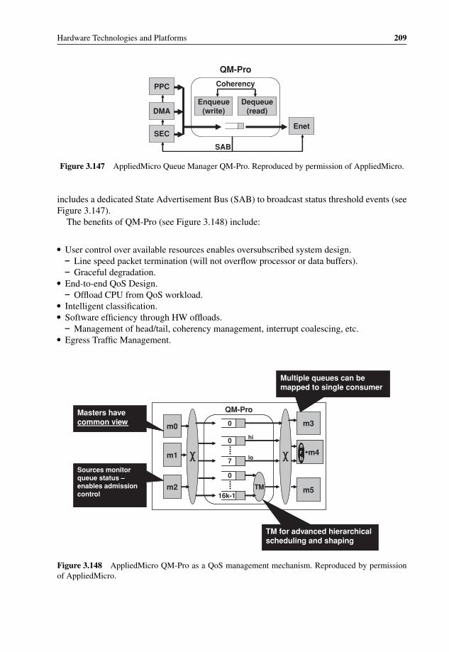
P1: OTA/XYZ P2: ABCc03 BLBK307-Bachmutsky September 2, 2010 13:12 Printer Name: Yet to Come
Hardware Technologies and Platforms 209
PPC
DMA
SECEnet
Enqueue(write)
Dequeue(read)
Coherency
SAB
QM-Pro
Figure 3.147 AppliedMicro Queue Manager QM-Pro. Reproduced by permission of AppliedMicro.
includes a dedicated State Advertisement Bus (SAB) to broadcast status threshold events (seeFigure 3.147).
The benefits of QM-Pro (see Figure 3.148) include:
� User control over available resources enables oversubscribed system design.– Line speed packet termination (will not overflow processor or data buffers).– Graceful degradation.
� End-to-end QoS Design.– Offload CPU from QoS workload.
� Intelligent classification.� Software efficiency through HW offloads.
– Management of head/tail, coherency management, interrupt coalescing, etc.� Egress Traffic Management.
0
0
7
0
16k-1TM
QM-Pro
m0
m1
m2
m3
m5
m4arb
Masters have common view
Sources monitor queue status –enables admission control
Multiple queues can be mapped to single consumer
TM for advanced hierarchical scheduling and shaping
hi
lo
Figure 3.148 AppliedMicro QM-Pro as a QoS management mechanism. Reproduced by permissionof AppliedMicro.

P1: OTA/XYZ P2: ABCc03 BLBK307-Bachmutsky September 2, 2010 13:12 Printer Name: Yet to Come
210 System Design for Telecommunication Gateways
D Cache32KB
I Cache32KB
L2 Interface
Branch FXU’s FPU
I Buffer
Decode
I Cache4KB
D Cache4KB
D Cache32KB
I Cache32KB
Branc Fh XU’s FPU
I Buffer
Decode
I Cache4KB
D Cache4KB
L2 Cache
L2 Interface
D Cache32KB
I Cache32KB
L2 Interface
Branch FXU’s FPU
Compute Complex Fabric (CCF)
I Buffer
Decode
I Cache4KB
D Cache4KB
D Cache32KB
I Cache32KB
Branch FXU’s FPU
I Buffer
Decode
I Cache4KB
D Cache4KB
L2 Cache
L2 Interface
Figure 3.149 AppliedMicro dual-core Titan block diagram. Reproduced by permission ofAppliedMicro.
AppliedMicro has presented at the 2007 Microprocessor Forum their new generation 32-bitTitan PowerPC core and Titan-based dual-core processor (see Figure 3.149).
The features of Dual-core Titan include:
� 2-way superscalar, out of order execution.� Double-precision FPU support.� 32-bit EA, 36-bit physical address.� Support 1 KB-4 GB variable page sizes.� Software transparent 4 K/4 K 2-cycle access L0 I-cache/D-cache, allows maintaining of low
latency at high frequency, especially in tight loops.� 32 K/32 K 5-cycle access L1 I-cache/D-cache, 64-way associative for improved utilization;
supports line locking, parity checking, MESI, and multiple hits under multiple misses.� 1 MB shared 14-cycle access L2 cache with ECC; dedicated L1-L2 interface with 16 GBps
per core throughput; 8-way set associative; supports MESI, line locking, partition to beSRAM (globally read/write), ECC protection, non-inclusive store policy, snoop filter.
� DDR2/DDR3 external memory interface reaches 9.6 GBps per port with full hardware cachecoherency; design can scale to multiple memory controllers.
� Full multicore SMP support with hardware cache coherency.� Performance Monitors: four counters with many events can be monitored.� Real-time trace port for instruction traces from multiple cores at the same time.

P1: OTA/XYZ P2: ABCc03 BLBK307-Bachmutsky September 2, 2010 13:12 Printer Name: Yet to Come
Hardware Technologies and Platforms 211
PCI & PCI-XCP,
CN50XX
• 1-2 cores
• 300 MHz to 700 MHz
CN63XX
• 2-6 cores
• Up to1.5Ghz
1 Core
2 Cores
4 Cores
6 Cores
8 Cores
10 Cores
24 Cores
16 Cores
32 Cores
OCTEON PLUS Processor Family
OCTEON II Processor Family
Up to 3x RGMII,
SCP options
Up to 8x RGMII, 2x SPI-4.2, PCI-X, EXP,
NSP, SCP options, Low power options Up to 8x SGMII, up to 2x
XAUI, up to 2x 8-lanes PCIe, CP, NSP, SCP orSP, SSP options, Low
power options
XAUI, sRIO, Interlaken,PCIe Gen2, SGMII, DDR3,
USB 2.0 AAP, CP versions, Low power options
CN50XX
• 1-2 cores
• 300 MHz to 700 MH z
CN58XX
• 4-16 cores
• 500 MHz to 800 MHz
CN56XX
• 8-12 cores
• 600 MHz to 800 MHz
CN54XX
• 4-6 cores
• 500 MHz to 700 MHz
CN57XX
• 8-12 cores
• 600 MHzto 800 MHz
CN55XX
• 4-6 cores
• 500 MHzto 700 MHz CN63XX
• 2-6 cores
• Up to1.5G hz
CN68XX
• Up to 32cores
• Up to1.5GHz
• 75application acceleration engines
CN52XX
• 2-4 cores
• 500 MHz to 750 MHz
Figure 3.150 Cavium Networks latest multicore processors. Reproduced by permission of Cavium.
3.5.6.2.3 Cavium NetworksCavium Networks is one of the market leaders in multicore processors with a range of excellenttechnologies; therefore, their products are reviewed here in more detail.
One of the most amazing features that practically everyone finds in Cavium Networks’products is the large number of different chips released by this relatively small and youngcompany. A quick check of the company website99 shows four security processors (Nitrox PX,Nitrox Lite, Nitrox, and Nitrox II) and thirteen distinct types of multicore OCTEON proces-sors (CN30XX, CN31XX, CN36XX, CN38XX, CN50XX, CN52XX, CN54XX, CN55XX,CN56XX, CN57XX, CN58XX, CN63XX and CN68XX; see some of them in Figure 3.150),not taking into account models CN2XX, CN5XX, CN10XX, CN11XX, CN13XX, CN15XX,CN16XX, CN21XX through CN25XX, standalone DPI content processor CN17XX andadditional differentiation within these groups: the presence or absence of some hardwareacceleration blocks (cryptography, RegEx, compression/decompression, RAID), number ofcores and the core frequency. Add some products utilizing architectures from acquired
99 http://www.caviumnetworks.com/Table.html.

P1: OTA/XYZ P2: ABCc03 BLBK307-Bachmutsky September 2, 2010 13:12 Printer Name: Yet to Come
212 System Design for Telecommunication Gateways
companies (ECONA single- and dual-core ARM processors with hardware offload for Layer2 switching and Layer 3/Layer 4 packet processing, PureVu video processors) and the pictureis astonishing.
The large variety of different chips allows Cavium Networks to target different markets withdifferent features and performance requirements, from 100 Mbps to full duplex 40 Gbps, forapplications such as routers, switches, unified threat management (UTM) appliances, content-aware switches, application-aware gateways, triple-play gateways, WLAN and 3G access andaggregation devices, storage networking equipment, servers and intelligent NICs.
CN30XX singlecore processors deliver the performance of 64-bit computing and integratedL2 cache at sub-$20 price points and 2–5 W power; the CN30XX is ideal for IEEE 802.11a/b/g/n, VDSL2, PON, triple-play, UTM, SOHO/SMB NAS, and VoIP applications. I/Osinclude Fast Ethernet, Gigabit Ethernet, TDM/PCM and USB 2.0. CN50XX processors havethe capability of higher core frequency (up to 700 MHz) in a hardware and software compatiblepackage with CN30XX.
CN31XX 4 W-7 W processors (see Figure 3.151) add to CN30XX dual-core capability,faster and wider DDR2 interface (36- or 72-bit wide, up to 667 MHz), replace PCI 32/66with faster PCI-X 32/133 and allow optional integrated compression/decompression and eightengines of pattern matching hardware acceleration. The cache system is also improved with
256KB SharedL2 Cache
256KB SharedL2 Cache
Hyper Access Memory
Controller
Hyper Access Memory
Controller
Coherent Bu s
72 bit wide – DDR IIup to 667MHz
I/O B
us
Sched/ Synch/ Order
Sched/ Synch/ Order
Packet Input
Packet InputPacket Input
Packet Input
Packet OutputPacket Output
I/O Bridge
I/OBridge
3x RGMIIor
1x RGMII + 1x GMII
Boot/flashGPIO
2xUART
32-bit, 100MHz
USBUSB
Packet InterfacePacket
Interface
Misc I/OMisc I/O
RNGRNG
PCI-XPCI-X
TCP UnitTCP Unit
USB 2.0Host w/PHY
8x RegExEngines
8x RegExEngines
Hyper Access Low Latency Memory Controller
Hyper Access Low Latency Memory Controller
Compress/ Decomp
Compress/ Decomp
1 - 2
cnMIPS
cores
Security
MIPS64 r2Integer
Packet
32K Icache
8K Dcache
2K Write Buffer
Security
MIPS64 r2Integer
Packet
32K Icache
8K Dcache
2K Write Buffer
Security
MIPS64 r2Integer
Packet
32K Icache
8K Dcache
2K Write Buffer
Security
MIPS64 r2Integer
Packet
32K Icache
8K Dcache
2K Write BufferTDM/PCMTDM/PCMTDM/PCM
256KB SharedL2 Cache
256KB SharedL2 Cache
Hyper Access Memory
Controller
Hyper Access Memory
Controller
Coherent Bus
72 bit wide – DDR IIup to 667MHz
I/O B
us
Sched/ Synch/ Order
Sched/ Synch/ Order
Packet Input
Packet InputPacket Input
Packet Input
Packet OutputPacket Output
I/O Bridge
I/OBridge
3x RGMIIor
1x RGMII + 1x GMII
Boot/flashGPIO
2xUART
32-bit, 100MHz
USBUSB
Packet InterfacePacket
Interface
Misc I/OMisc I/O
RNGRNG
PCI-XPCI-X
TCP UnitTCP Unit
USB 2.0Host w/PHY
16bit DDR2Optional
8x RegExEngines
8x RegExEngines
Hyper Access Low Latency Memory Controller
Hyper Access Low Latency Memory Controller
Compress/ Decomp
Compress/ Decomp
1 - 2
cnMIPS
cores
Security
MIPS64 r2Integer
Packet
32K Icache
8K Dcache
2K Write Buffer
Security
MIPS64 r2Integer
Packet
32K Icache
8K Dcache
2K Write Buffer
Security
MIPS64 r2Integer
Packet
32K Icache
8K Dcache
2K Write Buffer
Security
MIPS64 r2Integer
Packet
32K Icache
8K Dcache
2K Write BufferTDM/PCMTDM/PCMTDM/PCM
Figure 3.151 Cavium Networks CN31XX block diagram. Reproduced by permission of Cavium.
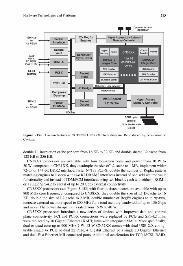
P1: OTA/XYZ P2: ABCc03 BLBK307-Bachmutsky September 2, 2010 13:12 Printer Name: Yet to Come
Hardware Technologies and Platforms 213
DDR2 up to
800MHz
72 or 144-bit wide
w/ECC
Coherent, Low Latency
Interconnect
I/O Bus
CN58XX
4 to 16cnMIPS64
cores
2MB SharedL2 Cache
Hyper Access Memory Controller
PacketInterface
SecureVault
Misc I/O
Compress/Decomp
PacketInterface
PacketInput
PacketOutput
Scheduler/Sync. Order
32x RegExEngines
Hyper Access Low Latency Memory Controller
I/O Bridge
PCI-X
TCP Unit
Boot/Flash,
CF, GPIO, DUART, I2C
64-bit133MHz
SPI 4.2or
4x RGMII
SPI 4.2or
4x RGMII
Optional 2x18-bitRLDRAM2
MIPS64 r2Integer Core
Packet
32K Icache
16K Dcache
2K Write Buffer
CryptoSecurity
MIPS64 r2Integer Core
Packet
32K Icache
16K Dcache
2K Write Buffer
CryptoSecurity
Figure 3.152 Cavium Networks OCTEON CN58XX block diagram. Reproduced by permission ofCavium.
double L1 instruction cache per core from 16 KB to 32 KB and double shared L2 cache from128 KB to 256 KB.
CN38XX processors are available with four to sixteen cores and power from 10 W to30 W; compared to CN31XX, they quadruple the size of L2 cache to 1 MB, implement wider72-bit or 144-bit DDR2 interface, faster 64/133 PCI-X, double the number of RegEx patternmatching engines to sixteen with two RLDRAM2 interfaces instead of one, add secured vaultfunctionality and instead of TDM/PCM interfaces bring two blocks, each with either 4 RGMIIor a single SPI-4.2 to a total of up to 20 Gbps external connectivity.
CN58XX processors (see Figure 3.152) with four to sixteen cores are available with up to800 MHz core frequency; compared to CN38XX, they double the size of L1 D-cache to 16KB, double the size of L2 cache to 2 MB, double number of RegEx engines to thirty-two,increase external memory speed to 800 MHz for a total memory bandwidth of up to 136 Gbpsand more. The power dissipation is rated from 15 W to 40 W.
CN52XX processors introduce a new series of devices with improved data and controlplane connectivity. PCI and PCI-X connections were replaced by PCIe and SPI-4.2 linkswere replaced by 10 Gigabit Ethernet (XAUI) links with integrated MACs. More specifically,dual to quad-core up to 900 MHz 7 W–13 W CN52XX comes with dual USB 2.0, config-urable single 4x PCIe or dual 2x PCIe, 4 Gigabit Ethernet or a single 10 Gigabit Ethernetand dual Fast Ethernet MII-connected ports. Additional acceleration for TCP, iSCSI, RAID,

P1: OTA/XYZ P2: ABCc03 BLBK307-Bachmutsky September 2, 2010 13:12 Printer Name: Yet to Come
214 System Design for Telecommunication Gateways
DDR2 up to
800MHz
1x or 2x 72-bit wide with ECC
Coherent, Low Latency
Interconnect
I/O Bus
CN56XX
8 to 12cnMIPS64
cores
2MB SharedL2 Cache
Hyper Access Memory Controller
Misc I/O
PacketInput
PacketOutput
TCP Unit
I/O Bridge
Boot/Flash, CF, GPIO, DUART, USB 2.0 w/ PHY, FE (MII), I2C
*x16 Serdes
Scheduler/Sync. Order
DMA Engines
4x SGMIIor 4x 1000B-X
or XAUI
4x SGMIIor 4x 1000B-X
or XAUI
PCIeCore
PCIeCore
PC
Ie E
ng
ine
Sw
itch
x4
x4
x4
x4
Compress/Decomp
MIPS64 r2Integer Core
Packet
32K Icache
16K Dcache
2K Write Buffer
CryptoSecurity
MIPS64 r2Integer Core
Packet
32K Icache
16K Dcache
2K Write Buffer
CryptoSecurity
MIPS64 r2Integer Core
Packet
32K Icache
16K Dcache
2K Write Buffer
CryptoSecurity
MIPS64 r2Integer Core
Packet
32K Icache
16K Dcache
2K Write Buffer
CryptoSecurity
RAID/De-Dup
Figure 3.153 Cavium Networks storage-oriented OCTEON CN57XX block diagram. Reproduced bypermission of Cavium.
de-duplication (elimination of redundant data in the storage applications) and a broad set ofencryption/decryption (including IEEE1619 for data-at-rest) support enables usage ofCN52XX in highly-integrated secure services router and low-cost storage switching, bridging,ATCA, AMC, MicroTCA, NIC, 3G/UMB, LTE and WiMAX wireless applications.
The CN55XX series enhances the capabilities of CN52XX with compression/decompression hardware acceleration, dual DDR2 memory controller, 1 MB of L2 cacheand more flexible external connectivity with sixteen SerDes links divided into either dual8-lanes PCIe, or 8x PCIe plus 4x PCIe plus either 4x Gigabit Ethernet SGMII or 10 GigabitEthernet XAUI. RAID acceleration on the CN55XX fully offloads the CPU by providing fullline-rate hardware XOR and Galois Field processing for efficient RAID 4/5/6 configurations.CN54XX devices are similar to CN55XX, but without storage-related hardware accelerationblocks.
CN57XX (see Figure 3.153) provides even higher integration with eight to twelve cores,2 MB L2 cache and capability of 8x SGMII or 2x XAUI. CN56XX devices are similar toCN57XX, but without storage-related hardware acceleration blocks.
The CN63XX series improves CN52XX with four to six 1.5 GHz cores, larger L1 and L2cache, support for high speed DDR3 memory, but most importantly for some applications itimplements Serial Rapid IO interfaces.
However, the ultimate integration ‘king’ is the newest CN68XX series of processors (seeFigure 3.154) manufactured using a 65 nm technology process, with up to thirty-two cores each

P1: OTA/XYZ P2: ABCc03 BLBK307-Bachmutsky September 2, 2010 13:12 Printer Name: Yet to Come
Hardware Technologies and Platforms 215
x4
x4 XAUI or 4x SGMII
DMA
Boot/Flash (NOR & NAND), CF, 16 GPIO, DUART, 2x I2C, 1x USB 2.0 w/PHY, 1xRG/MII
CN68XX
16-32cnMIPS II
cores
MIPS64 r2Integer Core
Packet
37K Icache
32K Dcache
2K Write Buffer
CryptoSecurity
MIPS64 r2Integer Core
Packet
37K Icache
32K Dcache
2K Write Buffer
CryptoSecurity
4MB SharedL2 Cache
2x Hyper Access Memory
Controller v2
PacketInput v2
Packet Output v2
FPAApplicationAcceleration
Manager
Misc I/O
TimersRAID /XOR
I/OBridge
Coproc.Bridge
TCP
Secure Vault
Power Optimizer
5 QLM’s
x20Gen2SERDES
x4
2x Hyper Access Memory
Controller v2
2 x 72b 2x 72b
XAUI or 4x SGMII
Interlaken
PCIev2x4
HFA(via Main Memory)
2x RXAUI x4
XAUI or4x SGMII
PCIe v2
x4
x4 XAUI or 4x SGMII
DMA
Boot/Flash (NOR & NAND), CF, 16 GPIO, DUART, 2x I2C, 1x USB 2.0 w/PHY, 1xRG/MII
CN68XX
16-32cnMIPS II
cores
MIPS64 r2Integer Core
Packet
37K Icache
32K Dcache
2K Write Buffer
CryptoSecurity
MIPS64 r2Integer Core
Packet
37K Icache
32K Dcache
2K Write Buffer
CryptoSecurity
MIPS64 r2Integer Core
Packet
37K Icache
32K Dcache
2K Write Buffer
CryptoSecurity
MIPS64 r2Integer Core
Packet
37K Icache
32K Dcache
2K Write Buffer
CryptoSecurity
4MB SharedL2 Cache
2x Hyper Access Memory
Controller v2
PacketInput v2
Packet Output v2
FPAApplicationAcceleration
Manager
Misc I/O
TimersRAID /XOR
I/OBridge
Coproc.Bridge
TCP
Secure Vault
Power Optimizer
5 QLM’s
x20Gen2SERDES
x4
2x Hyper Access Memory
Controller v2
2 x 72b 2x 72b
XAUI or 4x SGMII
Interlaken(ILK-LA in Pass 2)
PCIev2x4
HFA(via Main Memory)
2x RXAUI x4
XAUI or4x SGMII
PCIe v2
Figure 3.154 Cavium Networks newest OCTEON CN68XX block diagram. Reproduced by permissionof Cavium.
running at up to 1.5 GHz clock frequency, with 128 TLB entries, 32-way associative 38 KBL1 instruction cache and 32 KB of L1 data cache, 4 MB of L2 cache, four 1600 MHz generalpurpose DDR3 memory controllers and four dedicated controllers for pattern matching andother deep packet inspection tasks, x5 Interlaken compliant link and 20x SerDes links for up tofour PCIe v2 connections and up to 16x Gigabit Ethernet SGMII links or up to four 10 GigabitEthernet XAUI links. In addition to general speed-up in all hardware acceleration blocks,it implements the SNOW cryptography algorithm. Also, Regular Expression accelerationhas been re-designed to implement Hybrid Finite Automata (HFA), which is capable ofperforming regular expression lookups using DFA and NFA algorithms (see Section 3.5.5.1for more detail). A few of the ‘drawbacks’ of that level of integration and performance are alonger 9-stage pipeline, which is still impressive and very competitive, and a maximum powerdissipation of 60 W with all cores and all features included and activated.
Studying Cavium Networks’ processors leaves one with an impression of playing with Legoblocks in different products: take these and these blocks, connect between them by these andthese connections and create the solution for a new set of applications. In a way, this is a trueimpression, because this was exactly the design principle behind the engineering: to createsuch ‘Lego’-like blocks so as to be able to release powerful and flexible designs quickly. Thisis one of main reasons why Cavium Networks was able to develop so many high-performanceproducts applicable to many applications in such a short period of time.
The OCTEON architecture includes the following fundamental architectural elements (seeFigure 3.155):

P1: OTA/XYZ P2: ABCc03 BLBK307-Bachmutsky September 2, 2010 13:12 Printer Name: Yet to Come
216 System Design for Telecommunication Gateways
� Up to thirty-two cnMIPS cores running with up to 1.5 GHz clock frequency integrated ontoeach OCTEON processor. Each cnMIPS core implements MIPS64 release2 ISA, includingbit level instructions (a primary new feature in release 2.0 of the MIPS64 ISA: bit fieldprocessing, extraction and bit test branch types of instructions), little and big endian modessupport for both 32-bit and 64-bit operations, plus Cavium Networks specific acceleration
I/O Buses0 IPDB=IPD Bus (128-bit wide)0 PKOB= PKO Bus (64-bit wide)0 POB= Packet Output Bus (64-bit wide)0 I/O Bus is two buses: IOBI (input) and IOBO (output). Each is 64-bit wide.
Simplified Packet Interface Block
(XAUI, PCIe, SPI-4.2, PCI/PCI-X, SGMII,
RGMII, GMII, or MII)
PKI – Packet Input Block
CORE
FPA – Free Pool Allocator Unit
SSO - Schedule/Synchronization /
Order
IPD – Input Packet Data
PIP – Packet Input Processor
PKO – Packet Output Unit
IOB – I/O Bus Controller
Interface RX Port
I/O Bus
Interface TX Port
L2 Cache Controller (L2C)
CM
B
( 640-bit )
IPD
B
PK
OB
Bus KEY0 Buses without arrows are full
duplex.0 Buses with only one arrow are
uni-directional.
Deterministic Finite Automata (DFA) – Pattern Matching, content inspection
(security, etc)
Random Number Generator (RNG)
Key Memory (KEY)
Timer Unit (TIM)
Compression / Decompression
(ZIP) Unit
Fetch and Add Unit (FAU)
I/O Bus
L2 CACHE
DDR Buffer (DRAM)
( 51
2-bi
t )
L1 DCACHE
L1 ICACHE
DRAM Controller (LMC)
Write Buffers
CRC Engine
HASH Engine
CRYPTO Engine
NOTE: Some OCTEON processors do not have the HASH Engine, CRYPTO Engine, DFA, or ZIP. The exact Packet Interfaces provided also vary.NOTE: The SSO is also known as the POW (Packet / Order / Work) Unit.
POB32-bit,
74-bit, or 144-bit
Figure 3.155 Cavium Networks OCTEON hardware architecture. Reproduced by permission ofCavium.

P1: OTA/XYZ P2: ABCc03 BLBK307-Bachmutsky September 2, 2010 13:12 Printer Name: Yet to Come
Hardware Technologies and Platforms 217
hardware and extensions. The OCTEON C/C++ compiler and library calls enable users totake advantage of additional instructions that are OCTEON specific; having the capability toaccess all functions without a need for low-level programming languages is a big advantagecompared to, for example, NPU with comparable performance. cnMIPS cores are highlyoptimized (potentially the greatest achievement of the Cavium Networks engineers) with ashort pipeline (offering tremendous performance advantages in terms of keeping the pipelinefull and productive) and dual issue support. There are a number of enhancements:– The ability to handle efficiently unaligned loads and stores, which is beneficial not just
from a performance perspective, but also means that users do not have to expend significantdevelopment effort in order to find and fix unaligned accesses in their legacy software.
– Support for 32-bit and 64-bit population count instructions so as to ascertain the numberof bits that are set in a piece of data; this functionality is useful for networking applicationsworking frequently with bitmap structures – for example, the select() function in a socketsspecification.
– 64-bit register multiply.– Large TLB table (up to 128 entries) with flexible page sizes from 4 KB to 256 MB.– Expanded capability to prohibit specific memory accesses (Read and Execute Inhibit)
on a per-page basis; the feature is critical in security applications for DoS detection andprevention, protection against overflow attacks and malicious code.
– Atomic add to memory locations, which enables, for example, the implementation ofefficient statistics counters.
– Multiple instructions for controlling memory order in addition to the standard SYNCinstruction in the MIPS64 ISA.
One significant advantage of the cnMIPS core is its small size which allowed CaviumNetworks to include up to thirty-two such cores (in addition to other acceleration blocks) usingwell-established, conservative and low-cost 65 nm or 90 nm silicon processing technology. Onthe other hand, the price paid for such small core size is the lack of a hardware floating point. Itpractically disqualifies the core from use in a generic desktop or server applications; however,this was intentional, since these applications are not OCTEON’s focus. Many networkingapplications do not use floating point at all and for them it is better to have a larger number ofsmaller cores without the floating point.
Another much discussed100 architectural decision was that to keep the core singlethreaded.Multithreading definitely makes the core bigger and it is debatable which is better: a larger core(meaning fewer cores per chip) with higher performance or a larger amount of smaller coreswith lower performance. The answer depends partly on the specific hardware implementation(Cavium Networks claims that in their architecture there is less need to hide the memory accesslatency or other tasks beyond what can be served by up to thirty-two cores), but mostly on theapplication. In general, control plane applications can benefit from multithreading much morethan user plane processing.
It is important to emphasize another unique feature of the cnMIPS core, cryptography inte-gration. Most of the other vendors of security acceleration blocks (excluding Sun UltraSPARCT2 and T2 Plus, which also put the cryptography unit close to the core) have implementedsecurity offload by integration of one or more off-core shared acceleration engine(s). Each
100 http://www.multicorepacketprocessing.com/.

P1: OTA/XYZ P2: ABCc03 BLBK307-Bachmutsky September 2, 2010 13:12 Printer Name: Yet to Come
218 System Design for Telecommunication Gateways
scheme has its own advantages and disadvantages. A separate off-core block can be moreefficient for bulk encryption/decryption, because it allows CPU to make a cryptographyrequest and continue to perform other tasks until the command is finished. As a responseto this capability, Cavium Networks had added a parallel pipeline stage designed specificallyfor security commands in order to create some level of parallel processing and minimizethe impact on CPU. A dual instruction issue design with two additional security acceler-ation co-processor pipelines adds up to four pipelines which can all execute in parallel.In addition, on-core security becomes much more efficient when a large rate of requestshas to be supported, because it eliminates overhead and the additional latency needed totransfer data to and from the acceleration hardware for processing. One example would bean application that needs to establish a high rate of secured session creation (the creationof each tunnel requires multiple sequential security commands). Another example is a se-cured VoIP, when the small size of audio packets creates higher cryptography rates andmakes on-core operations significantly more efficient. A third example is the specification forcertain mobile cryptography algorithms being forced to work with small data chunks. On-core security can become a more flexible and future-proof solution when new cryptographyalgorithms are introduced, because it enables close cooperation between CPU and hardwareacceleration, where some functionality is implemented by software while the rest is done byhardware.
An interesting advantage that is a by-product of on-core security is the easily achievedscalability of security application performance with growing processing requirements. InOCTEON it is enough to just add another core; with other solutions there is a need toscale independently the shared hardware acceleration block as well. On the other hand, thedisadvantage is that in some cases there is no need for linear cryptography performancegrowth with a number of cores; in such a scenario a smaller shared hardware accelera-tion block can be more area-efficient. Clearly, the con vs. pro viewpoint depends on theapplication.
Each cnMIPS core integrates the following additional functionality:
� Acceleration for symmetric cryptographic algorithms: DES/3DES, AES (all modes),KASUMI, SNOW.
� Acceleration for security hash algorithms: MD5, SHA-1, SHA-256, SHA-512.� Modular exponentiation hardware for accelerating RSA and Diffie-Hellman operations.� Hardware for Galois field multiplication.� Hardware for generating CRC of any polynomial that is 32-bit or less. For example,
CRC10 accelerates AAL2 and CRC32 accelerates AAL5 protocol processing. Moreover,the CRC hardware accelerates ROHC (Robust Header Compression) protocol processing.The functionality can also be used to accelerate the calculation of hash functions, whichcan improve the performance of database applications and various table lookup algorithmssignificantly.
These accelerators are integrated into each cnMIPS core as additional co-processors.Users can invoke these co-processors either synchronously or asynchronously and eitherissue an instruction to invoke one of these co-processors and wait for the co-processor tocomplete the task, or let the co-processor run in the background while continuing with thesubsequent instructions.

P1: OTA/XYZ P2: ABCc03 BLBK307-Bachmutsky September 2, 2010 13:12 Printer Name: Yet to Come
Hardware Technologies and Platforms 219
As a result of the described implementation, cnMIPS achieves high instructions-per-cyclecount, high performance/MHz and low per-packet latency.
� The OCTEON cache hierarchy and memory sub-system are optimized for multicore pro-gramming, efficient data-sharing and minimal access latencies, with special cache featuresboosting cache hit rates, minimizing L2 cache pollution, avoiding unnecessary cache write-back transactions so as to improve efficiency of DRAM bandwidth utilization. Large writebuffer and aggressive write combine to maximize the probability of merging individual storetransactions together with boosting memory efficiency and performance. The OCTEON ar-chitecture also offers DMA engines to handle transactions between the cnMIPS cachehierarchy and I/O address space without stalling cnMIPS cores.
The OCTEON cache hierarchy includes separate instruction and data L1 caches on eachcnMIPS core and up to a 4 MB L2 cache that is shared by all cnMIPS cores and the I/O sub-system (I/O can write data directly into the cache; it enables one, for example, to prefetchpacket headers by hardware to bring data closer to the core and improve performance). TheOCTEON L1 data cache implements a hybrid write-through/write-back policy and the L2cache implements a write-back policy. With the OCTEON caching policy, when the core isready with the data, it will be written through to the L2 cache. The core that consumes thesame data can access it from the L2 cache right away. If both the L1 and L2 caches wouldimplement write-back policy when the data consuming core accesses the data, the L2 cachehas to perform snoop operations on all of the L1 caches; the L1 cache which has the newdata will have a dirty cache line for writing back to the L2 cache; all of that will cause anextra latency in accessing the shared data.
There are a number of other useful cache management optimization techniques imple-mented in OCTEON:– It is possible not to write-back the L2 cache data. In some applications, for example, there
is no need to keep a packet after sending it out to the external port. Therefore, it is possibleto save the memory bandwidth and power by not writing this data back into the memoryas is done in regular cache implementations.
– The L2 cache can be either used fully dynamically by all cores and the I/O system, oralternatively can be partitioned between them, which can bring better and more predictableperformance in some use cases.
– Multiple pre-fetch instructions enable the sending of data to the desired part of the cachehierarchy prior to the application actually using the data.
– It has already been mentioned that the I/O sub-system can deliver header data directlyinto the L2 cache, while the rest of the packet will be copied into the main memory.The scheme is very flexible and enables a high degree of control over such transfers (forexample, per virtual port) among the L2 cache, main memory, application accelerationengines and the I/O sub-system.
� A network of internal interconnects which run at the same frequency as the cnMIPS cores,each connecting just the relevant functional units. The high speed and dedicated connectionof the internal interconnects maximizes internal interconnects bandwidth while minimizingthe latency of data transfers.
The OCTEON on-chip interconnect architecture involves a network of coherent memorybuses (CMB) connected through a high performance I/O bridge to another network ofinterconnects connecting the I/O sub-system (IOB).

P1: OTA/XYZ P2: ABCc03 BLBK307-Bachmutsky September 2, 2010 13:12 Printer Name: Yet to Come
220 System Design for Telecommunication Gateways
DRAM
DRAM
Controller
Shared L2 Cache
Co
re
Co
re
IO
128 256
AddressStore
Fill/Inv
Figure 3.156 Cavium Networks OCTEON CN58XX coherent bus block diagram. Reproduced bypermission of Cavium.
In the OCTEON Plus architecture the CMB network consists of four split-transaction andhighly pipelined buses and connects all the cnMIPS cores, L2 cache controller, memorycontroller and I/O bridge. Specifically, a 128-bit interconnect carries data from the cnMIPScores and I/O bridge to the L2 cache, two 256-bit interconnects carry cache line fill datafrom the L2 cache to the cnMIPS cores and I/O bridge (see Figure 3.156). The OCTEON-IICN68XX architecture is expected to have even better and wider interconnects with crossbarcapabilities.
Between the L2 cache and memory there are dedicated interconnects for carrying read andwrite data operating in parallel. The CMB network boosts performance through completelyparallel paths for bringing in cache line fills from memory and sending evicted data tomemory. A 128-bit interconnect carries data to be written to memory for each of the memorycontrollers. A 512-bit interconnect carries data that are read from memory from each of thememory controllers.
The I/O subsystem includes controllers for the various I/O interfaces, all the applicationspecific offload and acceleration engines and the I/O bridge. The I/O subsystem is connectedthrough four 64-bit split-transaction and highly pipelined buses running at the core frequency.For example, the functional unit that automates the processing of receiving and classifyingpacket data connects directly with the I/O bridge over a dedicated 64-bit interconnectin addition to another shared 64-bit interconnect. The functional unit that automates thescheduling and transmission of packet data connects directly with the I/O bridge overanother dedicated 64-bit interconnect plus a shared 64-bit interconnect. This way, packetdata that are pre-processed by the OCTEON hardware automation are sent directly into theCMB network for processing by the cnMIPS cores over a dedicated interconnect, and viceversa for the packet data that are ready for being transmitted out.

P1: OTA/XYZ P2: ABCc03 BLBK307-Bachmutsky September 2, 2010 13:12 Printer Name: Yet to Come
Hardware Technologies and Platforms 221
� Application specific hardware acceleration units, including security processing algorithms,features for facilitating US government FIPS140-2 high levels certification, TCP process-ing, pattern matching, storage, table lookup, compression/decompression and others. Whencompared to other architecture approaches, which rely on software implementation of thesefunctions, the OCTEON architecture offers higher efficiency in terms of low power con-sumption and minimized development complexity. As opposed to some on-core accelerationfunctionality, the following functions are shared between all cores:– High performance compression/decompression engines that feature the DEFLATE algo-
rithm as defined in RFC 1951, ALDER32 checksum for ZLIB as defined in RFC 1950,CRC32 checksum for GZIP as defined in RFC 1952. These engines work through the in-struction list prepared by cnMIPS cores and complete the jobs in parallel without stallingthe cores. Off-core functionality here makes sense, because compression/decompressionworks usually on larger data blocks.
– Pattern matching and regular expression DFA engines (NFA engines are slightly different).The pattern rules are stored in low latency RLDRAM2 for the high end OCTEON productsor regular DDR2 memory for the entry level OCTEON products. The acceleration engineswalk through the rules and perform pattern matching on the relevant packet data in parallel.In addition, the RLDRAM2 memory serves as a low latency (about twenty-five cyclesin CN38XX) memory with cache bypass for generic cnMIPS software usage in case oflatency-sensitive applications; there are cnMIPS instructions for accessing the RLDRAM2memory. Another usage model of the low latency memory interface is to connect TCAMdevices for accelerating wild card comparisons. LA-1 (standard look-aside interface)based TCAM devices can be attached to the RLDRAM2 interface through a RLDRAM2-to-LA-1/QDR FPGA.
– Features for facilitating even higher levels of the US government Federal InformationProcessing Standards (FIPS) 140-2 certification managed by the Computer Security Divi-sion of National Institute of Standards and Technology (NIST). Examples of such featuresinclude cryptographic Random Number Generator (RNG), secured storage for securitykeys which cannot be accessed through I/O interfaces, and a pin for zeroing out all thestored keys.
– TCP/UDP acceleration, including TCP/UDP checksum generation and packet headerverification as a part of the packet receive/transmit automation. In addition, the OCTEONarchitecture includes unique hardware support for implementing many timers (see Figure3.157) required by TCP sessions (these high-precision timers can be used for otherpurposes as well) with support of sixteen separate timer wheels (bucketed rings, eachbucket corresponds to a different time slice) in CN38XX (taken as an example, thenumber 16 is chosen to make sure that each core can have at least one ring), softwareinsert and hardware queue work; and with fast entry invalidation.
Number of buckets in the ring and time interval between buckets are programmable.At each periodic bucket time expiration, HW processes the next bucket; it can traverse upto 80 million timer entries per second. Each timer entry within a bucket may be a workqueue entry pointer that the HW submits. Bucket is a chunked list, and HW frees chunksto the HW pool after using them. HW also resets the bucket data structure.
� Data-plane and control-plane I/O interfaces.OCTEON hardware supports CPU bypass. For example, it can be programmed to forwardwithout processing any packets received on one of the SPI-4.2 sub-channels to another

P1: OTA/XYZ P2: ABCc03 BLBK307-Bachmutsky September 2, 2010 13:12 Printer Name: Yet to Come
222 System Design for Telecommunication Gateways
WorkQueue Entry
WorkQueue Entry
WorkQueue Entry
HW submits
Allocated by SW, freed (to HW pool)
by HW
first chunk
num rem
cur. chunk
32B
HW zeroes num, rem Bucket
Bucket
Bucket
Bucket
Bucket
Bucket
Bucket
Bucket
Pro
gram
mab
le
Ring
Current Bucket
Periodic Timer (Programmable)
HW
L2/DRAM
WorkQueue Entry
WorkQueue Entry
WorkQueue Entry
HW submits
Allocated by SW, freed (to HW pool)
by HW
first chunk
num rem
cur. chunk
32B
HW zeroes num, rem Bucket
Bucket
Bucket
Bucket
Bucket
Bucket
Bucket
Bucket
Pro
gram
mab
le
Ring
Current Bucket
Periodic Timer (Programmable)
HW
L2/DRAM
Figure 3.157 Cavium Networks OCTEON timer hardware acceleration. Reproduced by permission ofCavium.
sub-channel on the second SPI-4.2 port. This functionality enables the building of chainedconfigurations with multiple OCTEON processors (see the example of CN38XX chainingin Figure 3.158) for more processing power, data and control plane processing separation;and other purposes.
� Highly configurable with per virtual port granularity packet receive, buffering, buffermanagement, flow classification, QoS and transmit processing hardware automation. Thefollowing packet processing functions are fully automated:– Packet receive, reassembly and transmit through networking or PCI type interfaces: Giga-
bit Ethernet ports, 10 Gigabit Ethernet ports, SPI-4.2 sub-channels, PCI, PCI-X or PCIechannels, Interlaken, etc.
– Automatic packet data buffer allocation and freeing, buffer management. Buffer can beallocated from and freed into one of the memory pools by software or hardware. Forexample, CN38XX can be configured with eight memory pools behaving as a stack (Last-In-First-Out – LIFO). The size of the pool is limited only by the size of physical memoryallocated for the pool and the number of packets in the pool is unlimited. For performancereasons the hardware keeps 2 K pointers on-chip and manages these pointers automaticallyas a buffer descriptor cache. If congestion is detected when pool capacity or bus capacityreaches a pre-configured threshold, the system tries first to apply backpressure for theincoming traffic and will start dropping packets using QoS-aware RED if this does nothelp.
– Layer 2 through Layer 4 input packet header parsing, exception checks and checksumcalculation: Layer 2 type, error checks (FCS, frame error, length mismatch, etc.); IPv4and IPv6 checks (checksum, malformed, TTL, options, etc.); Layer 4 (TCP/UDP) checks

P1: OTA/XYZ P2: ABCc03 BLBK307-Bachmutsky September 2, 2010 13:12 Printer Name: Yet to Come
Hardware Technologies and Platforms 223
PHY MAC
FICOcteonCN38XX
OcteonCN38XX
OcteonCN38XX
SPI-4.2 SPI-4.2 SPI-4.2 SPI-4.2
TCAM for
New Sessions Lookup
RLDRAM
18bits
72 or 144 bits
72 or 144 bits
72 or 144 bits
SYSTEM DRAM
SYSTEM DRAM
SYSTEM DRAM
Possible Interface Optionswith extra MAC or Switch:
• 48 FE ports
• 2G + 24 FE ports
• 20x 1 GE ports
• 48x 1 GE ports
Figure 3.158 Cavium Networks OCTEON chaining architecture based on HW CPU bypass. Repro-duced by permission of Cavium.
(checksum, length, TCP flags, bad port); creation of 5-tuple hash, map it to a tag pro-grammable per HW port; handling a packet based on the priority defined by a combinationof a default value, VLAN priority bits or DiffServ bits per port, or it can also take somevalues from a few pre-programmed locations in the packet; programmable amount ofpacket is copied into L2 cache and the rest is transferred to the main memory; in addition,the first 90+ bytes are copied into the created work descriptor passed to the software,so smaller packets are not copied into the main memory at all; large packets are dividedinto multiple chained buffers depending on the buffer size. Input packet header parsingcan be applied to any interface, even PCI, which allows expanding the interfaces (forinstance, adding more Ethernet ports) through PCI, PCI-X or PCIe intermediary withoutany handling modification.
– Up to 7-tuple flow classification with VLAN stacking support.– Packet ordering and scheduling is automatically managed by hardware without requiring
explicit software locking.– Traffic management with strict priority and WRR scheduling for packet transmit; hardware
also can free the buffer into its pool when the corresponding packet is transmitted; caninsert Layer 2 CRC/FCS, Layer 4 (UDP, TCP) checksum into the packet; can update forevery packet up to two 1–4 bytes counters by either subtracting 1 or the sent packet length;can perform a zero byte write for core memory polling or create a work entry (message)for the software to notify that the packet is sent and the buffer can be re-used (if hardwarefreed it) or recycled by the software.
– 8 levels of hardware managed QoS.� Highly configurable intelligent hardware automation for scheduling packet processing work
among all cnMIPS cores in order to maximize parallelism of processing among all thecnMIPS cores, while ensuring that the required ordering and atomic sequences are
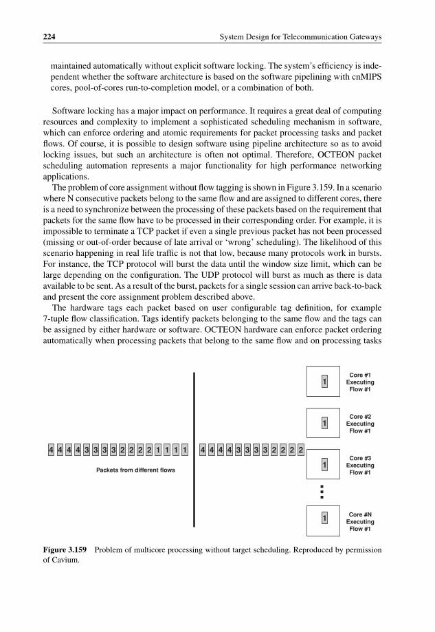
P1: OTA/XYZ P2: ABCc03 BLBK307-Bachmutsky September 2, 2010 13:12 Printer Name: Yet to Come
224 System Design for Telecommunication Gateways
maintained automatically without explicit software locking. The system’s efficiency is inde-pendent whether the software architecture is based on the software pipelining with cnMIPScores, pool-of-cores run-to-completion model, or a combination of both.
Software locking has a major impact on performance. It requires a great deal of computingresources and complexity to implement a sophisticated scheduling mechanism in software,which can enforce ordering and atomic requirements for packet processing tasks and packetflows. Of course, it is possible to design software using pipeline architecture so as to avoidlocking issues, but such an architecture is often not optimal. Therefore, OCTEON packetscheduling automation represents a major functionality for high performance networkingapplications.
The problem of core assignment without flow tagging is shown in Figure 3.159. In a scenariowhere N consecutive packets belong to the same flow and are assigned to different cores, thereis a need to synchronize between the processing of these packets based on the requirement thatpackets for the same flow have to be processed in their corresponding order. For example, it isimpossible to terminate a TCP packet if even a single previous packet has not been processed(missing or out-of-order because of late arrival or ‘wrong’ scheduling). The likelihood of thisscenario happening in real life traffic is not that low, because many protocols work in bursts.For instance, the TCP protocol will burst the data until the window size limit, which can belarge depending on the configuration. The UDP protocol will burst as much as there is dataavailable to be sent. As a result of the burst, packets for a single session can arrive back-to-backand present the core assignment problem described above.
The hardware tags each packet based on user configurable tag definition, for example7-tuple flow classification. Tags identify packets belonging to the same flow and the tags canbe assigned by either hardware or software. OCTEON hardware can enforce packet orderingautomatically when processing packets that belong to the same flow and on processing tasks
1111222233334444 222233334444
1
1
1
1
Packets from different flows
Core #1 Executing Flow #1
Core #2 Executing Flow #1
Core #3 Executing Flow #1
Core #N Executing Flow #1
Figure 3.159 Problem of multicore processing without target scheduling. Reproduced by permissionof Cavium.
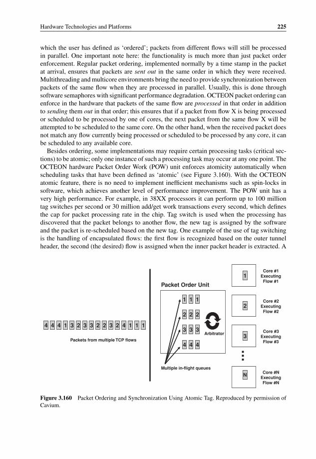
P1: OTA/XYZ P2: ABCc03 BLBK307-Bachmutsky September 2, 2010 13:12 Printer Name: Yet to Come
Hardware Technologies and Platforms 225
which the user has defined as ‘ordered’; packets from different flows will still be processedin parallel. One important note here: the functionality is much more than just packet orderenforcement. Regular packet ordering, implemented normally by a time stamp in the packetat arrival, ensures that packets are sent out in the same order in which they were received.Multithreading and multicore environments bring the need to provide synchronization betweenpackets of the same flow when they are processed in parallel. Usually, this is done throughsoftware semaphores with significant performance degradation. OCTEON packet ordering canenforce in the hardware that packets of the same flow are processed in that order in additionto sending them out in that order; this ensures that if a packet from flow X is being processedor scheduled to be processed by one of cores, the next packet from the same flow X will beattempted to be scheduled to the same core. On the other hand, when the received packet doesnot match any flow currently being processed or scheduled to be processed by any core, it canbe scheduled to any available core.
Besides ordering, some implementations may require certain processing tasks (critical sec-tions) to be atomic; only one instance of such a processing task may occur at any one point. TheOCTEON hardware Packet Order Work (POW) unit enforces atomicity automatically whenscheduling tasks that have been defined as ‘atomic’ (see Figure 3.160). With the OCTEONatomic feature, there is no need to implement inefficient mechanisms such as spin-locks insoftware, which achieves another level of performance improvement. The POW unit has avery high performance. For example, in 38XX processors it can perform up to 100 milliontag switches per second or 30 million add/get work transactions every second, which definesthe cap for packet processing rate in the chip. Tag switch is used when the processing hasdiscovered that the packet belongs to another flow, the new tag is assigned by the softwareand the packet is re-scheduled based on the new tag. One example of the use of tag switchingis the handling of encapsulated flows: the first flow is recognized based on the outer tunnelheader, the second (the desired) flow is assigned when the inner packet header is extracted. A
1114232233231444
222
333
444
1
2
3
N
Packets from multiple TCP flows
Core #1 Executing Flow #1
Core #2 Executing Flow #2
Core #3 Executing Flow #3
Core #N Executing Flow #N
111
Multiple in-flight queues
Arbitrator
Packet Order Unit
Figure 3.160 Packet Ordering and Synchronization Using Atomic Tag. Reproduced by permission ofCavium.

P1: OTA/XYZ P2: ABCc03 BLBK307-Bachmutsky September 2, 2010 13:12 Printer Name: Yet to Come
226 System Design for Telecommunication Gateways
similar effect occurs for compressed or encrypted flows: the first flow is able to decrypt and/ordecompress the packet correctly, the second flow comes when the header is extracted from theresulting packet; in the case of compressed, encrypted and encapsulated packet there can bemultiple tag switches during packet processing.
An additional flexibility offered by OCTEON is the capability to map processing tasks togroups of cores as opposed to a specific or any core. The assignments of cores to groups canchange dynamically in order to adapt to varying workloads. For example, the configurationcan be sixteen groups with one core in each group, or fewer groups with an arbitrary numberof cores in each group. The number of cores in each group does not need to be the same; thePOW HW will not schedule a piece of work if the core does not accept the group associatedwith the work. This additional flexibility has multiple advantages. First, applications can boostcache hit rate and performance by assigning a set of dedicated tasks and packet flows to adesignated group of cores. For example, one group of cores can handle control plane taskswith another group handling data plane processing. In this way, the locality of references tothe caches on these cores is optimized. Also, this function-based group association enablessending messages between functions utilizing hardware-based communication. Second, tasksthat are latency sensitive can be assigned to dedicated cnMIPS cores, thus avoiding head-of-line blocking scenarios. Third, certain cores can be dedicated for handling hardware interrupts,avoiding scheduling long latency tasks on these cores. As a result, interrupt response latencycan be optimized. Usually, cores in the same group will run the same software either in AMP,or SMP mode, but this is not strictly required from the hardware point of view.
A very important functionality of POW is the capability to deschedule a piece of work,which means that the SW running on this core will not complete the work at this time and thePOW HW should reschedule it later. The POW HW reschedules previously descheduled workat a higher priority than it schedules new work from an input queue. Deschedule can be usedto transfer the work to another group (for example, for pipelining), can free the core for otherwork if the current job has to wait for some internal or external synchronization event, or itcan just make a job interruptible if its processing takes too long.
There are a number of related hardware blocks in the OCTEON processor:
� Packet Output Unit (PKO)The OCTEON centralized Packet Output unit gathers packet data from cache or memoryand sends it out on any of the external interfaces. It can have a combined total of up tothirty-six output ports for sending packets. The packets sent out to the different ports sharesome of the same PKO HW resources, but logically the PKO unit treats the different in-flightpackets independently. The PKO API provides functions to configure an output port andthe associated queues, initialize PKO hardware and to send packets on a particular port andqueue.
� Packet Input Processing and Input Packet Data Unit (PIP/IPD)The PIP/IPD receives packet input data from any external interface, and can have a combinedtotal of up to thirty-six input ports for receiving packets. The packets arriving at the differentports share the same PIP/IPD HW resources, but logically the PIP/IPD HW treats thedifferent in-flight packets independently. The PIP/IPD units allocate and write packet datainto buffers in a format that is convenient to the software. The PIP/IPD also allocates andcreates a work queue entry for each packet. This work queue entry contains a pointer to

P1: OTA/XYZ P2: ABCc03 BLBK307-Bachmutsky September 2, 2010 13:12 Printer Name: Yet to Come
Hardware Technologies and Platforms 227
the buffered packet together with the first 96 bytes of the data, which can be pushed in thecache. It enables extremely efficient exchange of short messages.
� Free Pool Unit (FPA)The FPA unit maintains eight infinite-size pools of pointers to free memory. Software andother OCTEON HW units allocate and free pointers from/to the pools. Software and thecentralized input packet processing HW units allocate memory from the pools.
All of these units create a powerful combination of hardware-based memory and buffermanagement, message queuing, ordering and scheduling, together with APIs for full messageservicing in a user space domain.
The description above shows that there is an enormous hardware offload functionality inOCTEON processors. This is one of reasons why it sometimes referred to as the NPU. Ofcourse, it also has up to thirty-two general purpose MIPS64 cores, which is the reason whywe call it a hybrid CPU/NPU.
To summarize, it is useful to provide a comparison of the the technical specifications of thedifferent OCTEON models, as shown in Figure 3.161.
Another useful comparison is provided in Figure 3.162, which presents the performanceof a few OCTEON models with a different number of cores and core frequencies for IPv4packet forwarding application. It shows clearly that performance scales almost linearly withthe number of cores and frequency, which is the ultimate goal of any good packet processingdesign.
3.5.6.2.4 IBMThanks to the Sony PlayStation 3 gaming system, the IBM Cell processor101 is potentiallythe best known high-performance multicore processor. The target for Cell processor design(driven by IBM, Sony and Toshiba) was to improve PlayStation 2 gaming and multimediaperformance a hundred fold with future plans for 1000x. It was clear that conventional archi-tectures would not be able to achieve anything that even came close and it was agreed that thearchitecture would combine a 64-bit Power Architecture with memory control and multiple‘synergistic’ processors. In order to grasp the complexity of this project, it is worth mentioningthat the target price was $400 million, and that twelve IBM sites worldwide were involved inthe four-year development process, which included processor architecture, hardware imple-mentation, system structures and software programming models. Not surprisingly, the maindesign challenges were: (a) minimizing memory latency measured in processor cycles anddeveloping an architecture that allowed greater memory bandwidth by having more concurrentmemory access transactions; (b) improving power efficiency; (c) minimizing pipeline depthand making more efficient use of available time slots for each stage; (d) the requirement ofboth real-time behavior for pure gaming applications and non-real-time behavior for Internetaccess with the flexibility to run and accelerate many different Internet applications, includingvideo and voice, security, privacy, digital rights management, etc; (e) future-proof imple-mentation supporting many existing and future applications in the digital home environment,demanding Linux support; (f) a schedule that required using the Power Architecture as a baseto avoid new ISA development overhead and reuse of many existing applications, includingoperating systems.
101 http://www.research.ibm.com/cell/.

P1: OTA/XYZ P2: ABCc03 BLBK307-Bachmutsky September 2, 2010 13:12 Printer Name: Yet to Come
228 System Design for Telecommunication Gateways
OC
TE
ON
Par
t N
um
ber
sC
N38
XX
CN
58X
XC
N56
XX
CN
68X
XC
N63
XX
CP
U S
pee
d40
0MH
z to
600
MH
z60
0MH
z to
800
MH
z60
0-80
01G
Hz
to 1
.5G
Hz
1GH
z to
1.5
GH
z#
of
Co
res
4 -
164
- 16
8 -
1216
- 3
24
- 6
To
tal G
Hz
Up
to 9
.6G
Hz
Up
to 1
2.8G
Hz
Up
to 9
.6G
Hz
Up
to 4
8GH
zU
p to
12G
Hz
L2
Cac
he/
I/D-C
ach
e1M
B/3
2K/1
6K2M
B/3
2K/1
6K2M
B/3
2K/1
6K4M
B/3
7K/3
2K2M
B/3
7K/3
2KD
DR
Co
ntr
olle
rs1
x 14
4bit
DD
R2-
667
1 x
144b
it D
DR
2-80
02
x 72
bit D
DR
2-80
04
x 72
bit D
DR
3-16
001
x 72
bit D
DR
3-16
00
Ava
ilab
le S
erd
esN
/AN
/A12
Gen
1 S
erde
s (3
.125
Gbp
s)28
Gen
2 S
erde
s (6
.25G
bps)
12 G
en2
Ser
des
(6.2
5Gbp
s)
Hig
h S
pee
d I/
OU
p to
2 [S
PI-
4/ x
4 R
GM
II]U
p to
2 [S
PI-
4/ x
4 R
GM
II]U
p to
2 [X
AU
I/ x4
SG
MII]
+ M
II
Up
to 4
x [X
AU
I or
4x
SG
MIIs
] + 1
x [8
-lane
s In
terla
ken
+ 3
-lane
s In
terla
ken
LA] +
1x
RG
MII
1x [X
AU
I or
4x
SG
MII]
+ 1
x M
II +
1x
RG
MII
PC
IeP
CI-
X 6
4/13
3P
CI-
X 6
4/13
3U
p to
2 (
x1,x
2,x4
,x8)
v1
Up
to 2
x8
or 4
x4
PC
Ie v
2U
p to
2 x
4 P
CIe
v2
US
B2.
0 H
ost
/Dev
ice
N/A
N/A
No
21
I2C
22
Yes
22
Co
nte
nt
Insp
ecti
on
E
ng
ine
Yes
Yes
Yes
Yes
Reg
Ex
v3Y
es R
egE
x v3
Co
mp
ress
ion
/ D
eco
mp
ress
ion
Yes
Yes
Yes
Yes
2 en
gine
sY
es
Sec
uri
tyY
esY
esY
esY
es+
KA
SU
MI,
SN
OW
Yes
+ K
AS
UM
I, S
NO
WT
CP
Off
load
Yes
Yes
Yes
Yes
Yes
Lo
ad B
alan
cin
gY
esY
esY
esY
esS
SO
v2
Yes
GP
IO/U
AR
T16
/216
/216
/216
/216
/2F
lash
NO
R/C
FN
OR
/CF
NO
R/C
FN
OR
/NA
ND
NO
R/N
AN
DP
acka
ge
Typ
eF
CB
GA
(15
21)
FC
BG
A (
1521
)F
CB
GA
(12
17)
FC
BG
A (
TB
D)
FC
BG
A (
900)
Po
wer
Co
nsu
mp
tio
n15
W-4
0W17
W-4
0W17
W-3
5W32
W-6
5W8W
-20W
OC
TE
ON
PL
US
OC
TE
ON
II
Fig
ure
3.16
1C
ompa
riso
nof
Cav
ium
Net
wor
ksO
CT
EO
Npr
oces
sor
thre
ege
nera
tions
.Rep
rodu
ced
bype
rmis
sion
ofC
aviu
m.

P1: OTA/XYZ P2: ABCc03 BLBK307-Bachmutsky September 2, 2010 13:12 Printer Name: Yet to Come
Hardware Technologies and Platforms 229
Total GHz # Core Power Max (Core)
FD IP FWD (64B)
CN5230-500 2.0GHz 4 5.2W 3.3GbpsCN5230-750 3.0GHz 4 9.9W 4.7GbpsCN5434-600 3.6GHz 6 10.3W 5.6GbpsCN5650-600 7.2GHz 12 14.0W 11.3GbpsCN5830LP-500 2.0GHz 9.2W4 3.3GbpsCN5840LP-500 4.0GHz 8 11.2W 6.3GbpsCN5850LP-500 6.0GHz 12 13.2W 9.4GbpsCN5860LP-500 8.0GHz 16 15.4W 13.5GbpsCN5860LP-600 9.6GHz 16 17.6W 15Gbps
Figure 3.162 IPv4 packet forwarding performance scalability in Cavium Networks OCTEON proces-sors. Reproduced by permission of Cavium.
This is how the Broadband Processor Architecture (BPA) was created, combining in thefirst generations of Cell processor (see Figure 3.163) a 64-bit Power Architecture compliantup to 3.2 GHz Power Processor Element (PPE) with eight newly architected cooperativecoherent 3.2 GHz offload processors, called Synergistic Processor Elements (SPEs), sharedintegrated memory for efficient inter-processor communication and simplified programmingmodel, memory controller for high throughput dual Rambus memory blocks (supports totalmemory throughput of up to 25.6 GBps), test and debug logic and high bandwidth I/Ointerfaces (aggregate I/O bandwidth can be up to 85 GBps) supporting a single-chip andcoherent dual- and quad-chip configurations (see Figure 3.164; IOIF: Input–output interface;BIF: broadband interface), all interconnected with a very high bandwidth coherent on-chipElement Interconnect Bus (EIB) capable to transfer up to 96 bytes of data per cycle. PPEintegrates dual-threaded, dual-issue Power core with 32 KB L1 I- and D-caches, 512 KB L2cache and has ‘only’ a twenty-three-stage pipeline (IBM claims that it is significantly smallerthan that which can be expected for a design with so short a time per stage; we have to rememberthat Cavium Networks had to increase the pipeline in the latest CN68XX from five stages to
SXU SXU SXU SXU SXU SXU SXU SXU
LS LS LS LS LS LS LS LS
DMA DMA DMA DMA DMA DMA DMA DMA
On-chip coherent bus (up to 96 bytes per cycle)
SPE
L2
L1 Power Core
PPEMemory
controllerBus interface
controller
Dual RambusXDR
RambusFlexIO
Figure 3.163 IBM Cell processor block diagram. Reprint Courtesy of International Business MachinesCorporation, © 2005 International Business Machines Corporation.

P1: OTA/XYZ P2: ABCc03 BLBK307-Bachmutsky September 2, 2010 13:12 Printer Name: Yet to Come
230 System Design for Telecommunication Gateways
XDR XDR XDR XDR
XDR XDR XDR XDR
XDR XDR XDR XDR
XDR XDR
Cell processor
Cellprocessor
Cell processor
Cell processor
Cell processor
Cell processor
Cell processorIOIF0 IOIF1
IOIF IOIF
IOIF IOIF
IOIF IOIF
BIF
BIFBIFSwitch
Figure 3.164 IBM Cell processor system configurations. Reprint Courtesy of International BusinessMachines Corporation, © 2005 International Business Machines Corporation.
nine when increasing the clock from 800 MHz to 1.5 GHz. The Power core here is 3.2 GHzand the core pipeline is much more complex than MIPS64). The Power core in a Cell processoris simplified as compared to standalone chips by implementing only dual issue and withoutdynamic instructions reordering; instructions from both threads can be interleaved; arithmeticunits are very high performance with only two cycles for simple arithmetic and ten cycles fordouble-precision floating-point instruction; branch miss penalty is twenty-three cycles. Theprocessor is composed of three units: the instruction unit responsible for instruction fetch,decode, branch, issue and completion; a fixed point execution unit responsible for all fixedpoint load/store-type instructions with 32-entry 64-bit register file per thread; and a vectorscalar unit responsible for all vector and floating-point instructions with per-thread 32-entry64-bit register file for floating point and 32-entry 128-bit register file for vector unit.
PPE vector unit and SPEs use SIMD architecture, which is used by the majority of otherprocessors and enables reuse of software and development tools simplifying both chip designand programming.
Dynamically configurable SPEs (see Figure 3.165) have a large 256 KB local storagememory (mapped into global flat memory for easy addressing, but not coherent), asynchronouscoherent DMA supporting up to sixteen outstanding DMA commands, execution units (SXUs)and a large 128-entry register file to improve memory bandwidth, power efficiency andperformance.
Floating-point unit
Fixed-point unit
Permute unit
Load/store unit
Branch unit
Channel unit
Result forwarding and staging
Register file
Instruction issue unit/instruction line buffer
DMA unit
128B read 128B write
Local store (256 KB)
Single-port SRAM
On-chip coherent bus
8 bytes per cycle16 bytes per cycle
64 bytes per cycle
128 bytes per cycle
Figure 3.165 IBM Cell Synergistic Processor Element block diagram. Reprint Courtesy of Interna-tional Business Machines Corporation, © 2005 International Business Machines Corporation.
P1: OTA/XYZ P2: ABCc03 BLBK307-Bachmutsky September 2, 2010 13:12 Printer Name: Yet to Come
Hardware Technologies and Platforms 231
Local store memory in SPE can be used either to transfer data between SPE and otherblocks in the system including external memory, or as a scratch pad for SPE applications.On the other hand, local memory requires some memory management, increasing softwarecomplexity. SPE can perform simple fixed point operations in two cycles and load and single-precision floating point operations in six cycles. One important aspect of the architecture isthat SPE supports only a single program context at any given time; such a context can be eitherapplication or privileged/supervisor thread. At the same time SPEs are running as a part of thechip virtualization and support hypervisor operations controlled from the PPE.
The SPEs present some software and compiler challenges, including support for instructionprefetch capabilities and the significant branch miss penalties resulting from the lack ofhardware branch prediction. To achieve high rates of computation at moderate cost in power andarea, functions that are traditionally handled in hardware, such as memory realignment, branchprediction and instruction fetches have been partially offloaded to the compiler. Branchesare only detected late in the pipeline for reduced hardware complexity, faster clock cycles,and increased predictability; therefore, incorrect branch prediction incurs a heavy 18-cyclepenalty. The architecture includes a ‘branch hint’ instruction inserted by the compiler or by theprogrammer’s directive, which causes a prefetch of up to thirty-two instructions, starting fromthe branch target, so that the ‘correct’ branch incurs no penalty. In addition, select instructionshelp to eliminate short branches.
An additional SPE limitation is that it supports only 16-bit integer multiply-add instructions;hence, a 32-bit multiply instruction has to be supported in the software by using a series of16-bit multiply-add instructions.
IBM also has developed the auto-SIMDization functionality, which extracts SIMD paral-lelism from scalar loops and generates vector instructions from scalar source code for theSPEs and the VMX units of the PPE that were not designed for high performance scalar codeexecution. Also, the 128-bit wide memory access instructions require that the accessed datais aligned on the 16 bytes boundary, and the lower four bits of the address are simply ignoredin vector load or store instructions. To facilitate memory operations on a character or on aninteger value, there is an additional support to extract or merge such a value from or into a128-bit register.
SPE has limited local memory for both code and data, and in some cases it cannot fit.To solve the problem, the compiler divides the SPE program into multiple partitions on thefunction level boundary, which are overlaid during linking by assigning the same startingvirtual address, so the SPE code size becomes equal to the largest code partition. Of course,overlaid partitions cannot run at the same time, implying that a function call between partitionscauses the code to be swapped in and out of the local store during the function call and return.This is facilitated by the automatic addition of the compact and efficient always residentpartition manager (see Figure 3.166) responsible for loading the next active code partition.The code is modified automatically to replace the direct function call with a call to the partitionmanager.
More information about special compiler techniques for the Cell processor can be found inthe article written in 2006 by A.E. Eichenberger, et al., ‘Using advanced compiler technologyto exploit the performance of the Cell Broadband EngineTM architecture’.102
102 http://domino.watson.ibm.com/comm/research_people.nsf/pages/zsura.publications.html/$FILE/ibmsystem06_cellCompiler.pdf.

P1: OTA/XYZ P2: ABCc03 BLBK307-Bachmutsky September 2, 2010 13:12 Printer Name: Yet to Come
232 System Design for Telecommunication Gateways
PPEDriver
Partition Data
Embedded User Program
Embedded SPE Driver
Data Skeleton
Partition Manager
Partition Table
Code Buffers
Executing PPE Binary
SPE Execution
Create SPE driver thread
PPE Driver
Partition Data
Data
Partition Manager
overlay 1
overlay 2
overlay 3
overlay N
Embedded SPE Driver
Executing PPE Binary
Data
Partition Manager
Partition Table
Code Buffers
overlay 1
SPE Execution
Initialize: Copy partition data
and root overlay from
system memory
PPE Driver
Partition Data
Embedded SPE Driver
Data
Partition Manager
overlay 1
overlay 2
overlay-m
overlay N
Executing PPE Binary
Data
Partition Manager
Partition Table
Code Buffers
overlay-n
overlay-m
SPE Execution
Control flowDMA transfer
ii) Pass control to
appropriate address in
new overlay
Interpartition calli) Transfer new overlay from
system memory
Figure 3.166 IBM Cell automatic code partitioning. Reprint Courtesy of International BusinessMachines Corporation, © 2005 International Business Machines Corporation.
SPEs can be used in the Cell processor in a number of ways. One is when it is used for spe-cific function acceleration and remote access commands are inserted in the code for a functioninvocation in both directions. This mode can be enhanced into full application accelerationwhen the PPE performs only general management functions and load balancing between SPEsto achieve better parallelization. Another is to use SPE as an external device ‘proxy’, whichmanages all communication with the device including optional pre- and post-processing of thetransferred data. A similar concept can be applied for data streaming through SPE betweenother modules; and SPE performs some data management, processing, modification and for-warding. Also, SPE and PPE can work in a fully cache-coherent shared-memory programmingmodel, when the Cell processor has processing units with two different instruction sets. Inthis mode standard memory load instructions are replaced by smart DMA transfers betweenexternal memory or caches and SPE local memory. The SPE can also function in AMP modewith assigned thread affinity.
A more detailed description of the Cell processor, including the history of the project, theprogram objectives and challenges, the design concept, the architecture and programmingmodels and implementation, can be found, for example, in the paper ‘Introduction to the CellMultiprocessor’ [Multicore-IBM-CellIntroduction] published in 2005 by J. A. Kahle and hiscolleagues from the IBM Systems and Technology Group.
The PowerXCell 8i adds high-speed double-precision to the single precision speed of theprevious generation Cell processor. On the PowerXCell 8i, the double-precision units are fully

P1: OTA/XYZ P2: ABCc03 BLBK307-Bachmutsky September 2, 2010 13:12 Printer Name: Yet to Come
Hardware Technologies and Platforms 233
pipelined, resulting in seven times faster (one result per cycle) double-precision instructionexecution than its predecessor at a rate of 12.8 GFLOPS for 3.2 GHz core frequency (3.2GHz x 2 64-bit floating-point words x 2 64-bit floating-point operations) totalling more than100 GFLOPS for the entire chip. It is worth mentioning that the total design power for thePowerXCell 8i is 92 watts.
The PowerXCell 8i also includes a redesigned memory controller to address larger (64 GBas opposed to a previous 1 GB), more standard and lower cost ECC-enabled 144-bit wide800 MHz DDR2 memory without any system memory bandwidth degradation.
IBM recommends using the Cell processor for compute-intensive applications, such as datamanipulation (digital media, image and video processing, output visualization, compression/decompression, encryption/decryption, DSP), graphics, floating point intensive applications,pattern matching (bioinformatics, string manipulation, parsing, transformation and translation,filtering and pruning), offload engines (TCP/IP, XML, network security and intrusion detectionand prevention) and others.
IBM offers PowerXCell 8i with a multitiered programming environment that includes anative programming layer (tier 1), a library and programming framework assisted layer (tier2) and a number of fully-featured application development environments (tier 3).
The first commercially available Cell-based platforms are the IBM BladeCenter bladesQS20 and QS21103, which are based on the previous generation of dual Cell processors, andQS22104 with two PowerXCell 8i processors.
Although of little importance for the purposes of this book, it is still worth mentioning thatIBM announced in 2008 the availability of a supercomputer called Roadrunner, built with12 240 PowerXCell 8i chips and 6120 dual-core AMD Opteron processors, all interconnectedby InfiniBand links, with a total processing power of more than 1.3 PFLOPS. Few multicoreprocessors can claim such performance scalability.
With all these advantages, IBM may not continue Cell processor development beyond thePowerXCell 8i. Plans to release the next generation of PowerXCell 32i chip with dual PowerPCcores and thirty-two SPEs are not clear, but IBM has stated that hybrid processing technologydevelopment will continue and will be incorporated in the next generation of IBM processors.
Of course, IBM continues to develop the PowerPC line of processors, including the embed-ded processors. IBM has realized the real power of low-power chips and their Blue Gene/Phigh-performance computer is built using quad-core PowerPC-450 850 MHz CPUs enablingsqueezing 1024 CPUs per rack. Also, based on their February 2009 announcement, IBM isworking on the next generation Blue Gene/Q supercomputer called Sequoia, which will prob-ably house the new generation of eight-core or sixteen-core PowerPC processors. Hopefully,the telecommunications industry will be able to benefit from this development, also.
3.5.6.2.5 IntelWe will not describe here the well-known Intel processors, but focus instead on their efficientuse for data plane processing and on a number of unique projects and ideas coming from thisgreat semiconductor company.
One such idea that we would like to see in every multicore processor is the overclocking ofone core when the processor ‘is operating below power, current, and temperature specification
103 http://www-03.ibm.com/systems/bladecenter/hardware/servers/qs21/index.html.104 http://www-03.ibm.com/systems/bladecenter/hardware/servers/qs22/index.html.

P1: OTA/XYZ P2: ABCc03 BLBK307-Bachmutsky September 2, 2010 13:12 Printer Name: Yet to Come
234 System Design for Telecommunication Gateways
.
Memory Sharing & Stacking
High Bandwidth I/O &
Communications
Scalable Multicore Architectures
Thread-Aware Execution Environment
Model-Based Applications
ParallelProgramming
Tools & Techniques
Figure 3.167 Intel’s Tera-scale Computing Research Program vision. Reproduced by Intel.
limits’105 (such as when other core(s) are idling for any reason). One use for such a modeis to boost single thread performance if needed. Another case is based on the fact that ina real application there are always periods when one or more cores are stalled waiting forsome events. In the latter scenario hardware multithreading sometimes helps, but has its ownlimitations and drawbacks. Active cores overclocking is a much more elegant solution, butit is not easy to implement. Intel processors are very good at that and there are many toolsenabling overclocking desktop CPUs by large margins assuming that the chip can be cooledefficiently, which requires either extra cooling designed to be able to dissipate more power,or just the fact that some cores are inactive and do not create the same amount of heat. Evenoverclocking by 15%–20% during periods when other cores are waiting for I/O or memorytransactions to finish would improve overall processor performance significantly. Multicorevendors, are you reading this?
Unfortunately, Intel has been relatively slow in its development of multicore and many-core embedded processors compared to other vendors such as Cavium Networks, NetLogic,Plurality, Tilera, Sun and a few others. However, they are working on a new generation ofdevices. Intel’s Tera-scale Computing Research Program106 is targeting scalability at hundredsof cores and is shifting to a parallel programming model. The program’s vision is shown inFigure 3.167 and was presented in more detail at the Intel Developers Forum in 2007.
The first prototype is the 62 W 3.16 GHz Teraflops Research Chip manufactured using 65nm technology with eighty simple cores in tiled design (see Figure 3.168), each containingtwo programmable floating point engines and integrated 5-port communication router. Tilescan be built using general purpose processors, or special purpose processors, or hardwareaccelerators. Tiled design has a number of advantages: (a) regular layout; (b) elimination ofglobal wiring and corresponding scalability issues; (c) faster design and convergence timebecause of modularity; (d) enables different types of application; (e) lower resource overhead.
All communication routers form a 2D mesh interconnect network. One of Intel’s argumentsfor a mesh network is the bisection bandwidth explained in Figure 3.169: if we assume thateach interconnect has the same throughput and that the traffic is distributed uniformly, in the2D mesh network the application has the most available bandwidth.
105 http://www.intel.com/technology/turboboost/.106 http://www.techresearch.intel.com/articles/Tera-Scale/1421.htm.
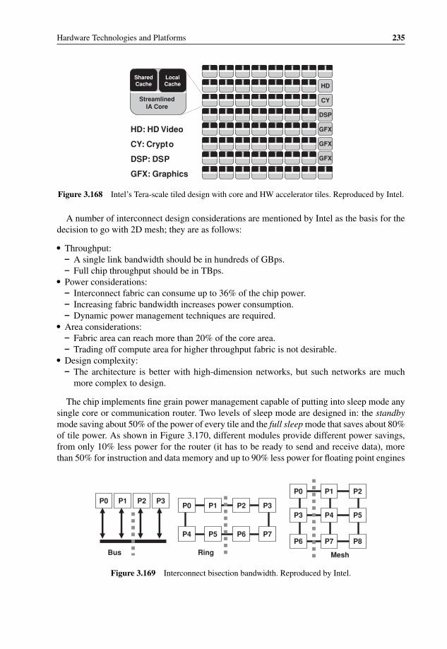
P1: OTA/XYZ P2: ABCc03 BLBK307-Bachmutsky September 2, 2010 13:12 Printer Name: Yet to Come
Hardware Technologies and Platforms 235
HD
CY
DSP
GFX
GFX
GFX
SharedCache
LocalCache
Streamlined IA Core
HD: HD Video
CY: Crypto
DSP: DSP
GFX: Graphics
Figure 3.168 Intel’s Tera-scale tiled design with core and HW accelerator tiles. Reproduced by Intel.
A number of interconnect design considerations are mentioned by Intel as the basis for thedecision to go with 2D mesh; they are as follows:
� Throughput:– A single link bandwidth should be in hundreds of GBps.– Full chip throughput should be in TBps.
� Power considerations:– Interconnect fabric can consume up to 36% of the chip power.– Increasing fabric bandwidth increases power consumption.– Dynamic power management techniques are required.
� Area considerations:– Fabric area can reach more than 20% of the core area.– Trading off compute area for higher throughput fabric is not desirable.
� Design complexity:– The architecture is better with high-dimension networks, but such networks are much
more complex to design.
The chip implements fine grain power management capable of putting into sleep mode anysingle core or communication router. Two levels of sleep mode are designed in: the standbymode saving about 50% of the power of every tile and the full sleep mode that saves about 80%of tile power. As shown in Figure 3.170, different modules provide different power savings,from only 10% less power for the router (it has to be ready to send and receive data), morethan 50% for instruction and data memory and up to 90% less power for floating point engines
P0 P1 P2 P3
Bus
P0 P1 P2 P3
P4 P5 P6 P7
Ring
P0 P1 P2
P3 P4 P5
P6 P7 P8
Mesh
Figure 3.169 Interconnect bisection bandwidth. Reproduced by Intel.

P1: OTA/XYZ P2: ABCc03 BLBK307-Bachmutsky September 2, 2010 13:12 Printer Name: Yet to Come
236 System Design for Telecommunication Gateways
Data MemorySleeping:
57% less power
Instruction Memory Sleeping:
56% less power
RouterSleeping:
10% less power (stays on to pass
traffic)
FPEngine 1
Sleeping: 90% less
power
FPEngine 2
Sleeping: 90% less
power
21 sleep regions per tile (not all shown)
Dynamic sleep
STANDBY:
• Memory retains data
• 50% less power/tile
FULL SLEEP:
• Memories fully off
• 80% less power/tile
Figure 3.170 Intel fine grain power management for tera-scale project. Reproduced by Intel.
if not in use. In total, Intel is planning to manage twenty-one separate sleep regions for everytile. Intel has also introduced additional instructions to enable applications to put a processorto sleep or wake it up. Also, Intel proposes improving power management significantly byenabling the control of voltage and clock per core or a cluster of cores.
In addition to power management, Intel is also studying thermal management. Onepossibility is to implement core hopping from hot chip areas to colder areas in order toachieve more even temperature distribution throughout the chip, improving performanceand reliability. Yet another possibility is to perform core scheduling, taking into account thecurrent chip thermal profile.
Not surprisingly, the prototype shows that the only way to scale the design is to add moreand more cores, because clock increase has poor power characteristics with power dissipationreaching 175 W when a 5.1 GHz clock is used and 265 W with 5.7 GHz.
Figure 3.171 Intel 3D stacked memory technology. Reproduced by Intel.

P1: OTA/XYZ P2: ABCc03 BLBK307-Bachmutsky September 2, 2010 13:12 Printer Name: Yet to Come
Hardware Technologies and Platforms 237
APP1
APP2
SCHEDULING
“Thin” SW component
Integratedhardware
CORE1 CORE2
CORE3 CORE4
Figure 3.172 Hardware accelerated task scheduler. Reproduced by Intel.
Another technology used by Intel is the 3D stacked memory, as shown in Figure 3.171. Itenabled the integration of 256 KB memory per core. Each core is connected to 3D stackedmemory, which is based on TSV (Through Silicon Vias) technology which puts the thinmemory die on top of the CPU die, letting the power and IO signals go through memory to CPU.
This is not the only development in this area. For example, NEC Corporation announcedin February 2009107 the development of chip-stacked flexible memory, which can be used toachieve a new system-on-chip (SoC) architecture and has the benefits of both fast embeddedmemory access and large general-purpose memory size. Interestingly, NEC is targeting large-scale SoC or high-performance tiled core designs, similar to Intel’s Tera-scale chip. Whatevertechnology will be used in the final mass-market product, it is a promising development.
An additional item of technology being proposed by Intel is the hardware accelerated low-overhead task scheduler (see Figure 3.172) of many fine-grained tasks, which can doubleperformance of some applications.
There are also some ideas for enhanced virtualization, where all components can be virtual-ized and the application isolation be enforced by interconnect of arbitrarily shaped independentdomains. However, one problem with such arbitrary shapes is that the failure of a few corescan cause other fully functional cores to become unusable, because failed cores could serveas routers to the rest of the domain. To solve this problem, Intel is working on the concept ofdynamic fault discovery and domain reconfiguration, as shown in Figure 3.173.
As one of steps in the parallel computational model, Intel has developed the TransactionalMemory concept in order to support the ‘atomic’ and ‘isolated’ execution of multiple tasksusing the transactional memory C++ language construct extensions.
Another Intel research project in parallel computing is Ct, or C/C++ for ThroughputComputing, which is described well in the whitepaper ‘Ct: A Flexible Parallel ProgrammingModel for Tera-scale Architectures’.108 The basic idea is that applications exhibit a great dealof parallelism while collecting data. Ct provides extensions to address irregular applications;many telecommunication applications are irregular, because they use dynamic data types,such as sparsely populated tables, trees and link lists. Ct is deterministic in nature and itsbehavior is the same independent of the number of cores in the system, from a singlecoreto manycore. Intel estimated that a C++ programming language affects performance at alevel of 20% to 30% compared to assembly programming. With parallel Ct programming,the Impact on performance is estimated at about 30%, which might be acceptable taking intoaccount relative programming simplicity (programmer still uses a serial design) and extensiveparallelism achieved.
107 http://www.nec.co.jp/press/en/0902/1001.html.108 http://www.techresearch.intel.com/UserFiles/en-us/File/terascale/Whitepaper-Ct.pdf.
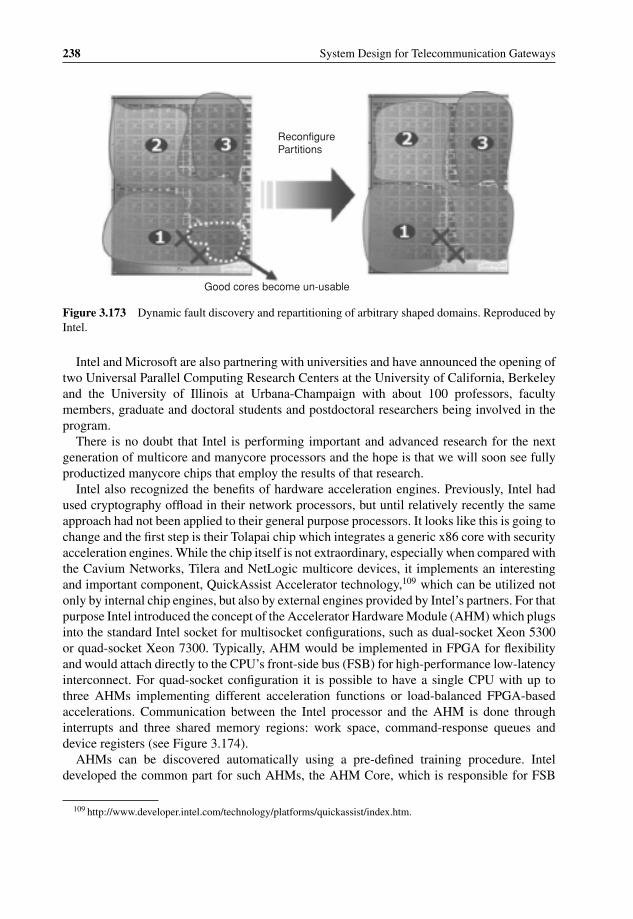
P1: OTA/XYZ P2: ABCc03 BLBK307-Bachmutsky September 2, 2010 13:12 Printer Name: Yet to Come
238 System Design for Telecommunication Gateways
Good cores become un-usable
ReconfigurePartitions
Figure 3.173 Dynamic fault discovery and repartitioning of arbitrary shaped domains. Reproduced byIntel.
Intel and Microsoft are also partnering with universities and have announced the opening oftwo Universal Parallel Computing Research Centers at the University of California, Berkeleyand the University of Illinois at Urbana-Champaign with about 100 professors, facultymembers, graduate and doctoral students and postdoctoral researchers being involved in theprogram.
There is no doubt that Intel is performing important and advanced research for the nextgeneration of multicore and manycore processors and the hope is that we will soon see fullyproductized manycore chips that employ the results of that research.
Intel also recognized the benefits of hardware acceleration engines. Previously, Intel hadused cryptography offload in their network processors, but until relatively recently the sameapproach had not been applied to their general purpose processors. It looks like this is going tochange and the first step is their Tolapai chip which integrates a generic x86 core with securityacceleration engines. While the chip itself is not extraordinary, especially when compared withthe Cavium Networks, Tilera and NetLogic multicore devices, it implements an interestingand important component, QuickAssist Accelerator technology,109 which can be utilized notonly by internal chip engines, but also by external engines provided by Intel’s partners. For thatpurpose Intel introduced the concept of the Accelerator Hardware Module (AHM) which plugsinto the standard Intel socket for multisocket configurations, such as dual-socket Xeon 5300or quad-socket Xeon 7300. Typically, AHM would be implemented in FPGA for flexibilityand would attach directly to the CPU’s front-side bus (FSB) for high-performance low-latencyinterconnect. For quad-socket configuration it is possible to have a single CPU with up tothree AHMs implementing different acceleration functions or load-balanced FPGA-basedaccelerations. Communication between the Intel processor and the AHM is done throughinterrupts and three shared memory regions: work space, command-response queues anddevice registers (see Figure 3.174).
AHMs can be discovered automatically using a pre-defined training procedure. Inteldeveloped the common part for such AHMs, the AHM Core, which is responsible for FSB
109 http://www.developer.intel.com/technology/platforms/quickassist/index.htm.

P1: OTA/XYZ P2: ABCc03 BLBK307-Bachmutsky September 2, 2010 13:12 Printer Name: Yet to Come
Hardware Technologies and Platforms 239
Intel®Xeon®
AHM
Memory
WORKSPACE
COMMAND RESPONSE
QUEUES
DEVICE REGISTERS
FS
B
FS
B
SystemMemory
Inter-ProcessorInterrupts
(IPI)
Controller Hub
Figure 3.174 Intel Accelerator Hardware Module concept. Reproduced by Intel.
interface logic, low-level device interface and one or more pre-defined bi-directional data andcommand FIFO interfaces to partner’s Accelerator Function Units (AFU) implementing therequired algorithms acceleration (see Figure 3.175).
In addition to the architecture and AHM Core FPGA code, Intel has also developed lowlevel software modules, such as kernel-level drivers and Accelerator Abstraction Layer (AAL)simplifying software development for QuickAssist acceleration integration by providing ready-made support for generic accelerator discovery, configuration and messaging services. AALhides from the software the actual accelerator function location, being implemented either asa tightly coupled FSB-based module or loosely coupled PCIe-based (or any other interface forthat purpose) module. The capability to utilize various interfaces is very important, especiallywhen taking into account that Intel FSB is going to be fully replaced in the new generation ofdevices.
There is already an ecosystem of QuickAssist partners that is developing a number ofacceleration modules; some FPGA-based acceleration solutions are described in Section3.5.2.4. Another example is the performance improvement offered by the Netronome NPU-based PCIe board which can speed-up many packet processing applications significantly, suchas packet capture performance, as shown in Figure 3.176.
The QuickAssist idea would be much more compelling if different processor vendors wereable to agree upon the processor-independent standard interface with AFUs being able toconnect to different processor types through processor-specific interface and protocol module.
3.5.6.2.6 FreescaleThe Freescale QorIQ P4080 Communication Processor has already been mentioned brieflyin Section 3.1.2.4 (see Figure 3.35). In less than a 30 W package it integrates eight PowerArchitecture e500 mc cores operating at up to 1.5 GHz frequency, each with a 32 KB Instruction

P1: OTA/XYZ P2: ABCc03 BLBK307-Bachmutsky September 2, 2010 13:12 Printer Name: Yet to Come
240 System Design for Telecommunication Gateways
Application
User library
Application Interface
Buffer (AIB)
Accelerator Abstraction Services (AAS)
Host AFU (Proxy)
Unified Accelerator Interface (UAI)
Bus Specific Driver
Accelerator Abstraction Layer (AAL)
User
Kernel
Task Queue
Task Descriptors
AHM HardwareAFUe
0AFUe
1AFUe
2AFUe
nCSR
Data
Figure 3.175 Intel QuickAssist System Architecture block diagram. Reproduced by Intel.
and Data L1 cache and a private 128 KB backside L2 cache, shared 2 MB frontside L3 cacheand three privilege levels of instructions for the implementation of efficient virtualization: user,supervisor and hypervisor. The hierarchical internal interconnect fabric supports coherent andnon-coherent transaction with 800 Gbps coherent read throughput and a built-in queue managerfor QoS-aware scheduling. High memory bandwidth is ensured by dual 64-bit DDR2/DDR3memory controllers with ECC and interleaving support. The P4080 is designed to serve bothdata and control plane applications. As a result, it includes two 10 Gigabit Ethernet and eight1 Gigabit Ethernet ports, three PCI Express v2.0 ports running at up to 5 GHz, two SerialRapidIO 1.2 ports running at up to 3.125 GHz and a number of data plane processing hardwareacceleration engines: packet parsing, classification and distribution; queue management forscheduling, packet sequencing and congestion management; hardware buffer management forbuffer allocation and de-allocation; cryptography; and RegEx pattern matching. Some detailabout the P4080 and P4040 data plane acceleration architecture was disclosed by Freescaleat the Linley Tech Processor Conference in 2009. As shown in Figure 3.177, ingress packetprocessing includes the Queue Manager (QMan), the Buffer Manager (BMan) and the FrameManager (FMan). To scale connectivity to cores efficiently, the cores’ interconnect, CoreNet,is built using multiple address buses and a high bandwidth data crossbar.
Frame Manager supports one 10 Gigabit Ethernet and 4 Gigabit Ethernet interface (totalparsing and classification capacity is limited to 12 Gbps), Layer 2/Layer 3/Layer 4 proto-col parsing and validation (including user-defined protocols), hash-based and exact match

P1: OTA/XYZ P2: ABCc03 BLBK307-Bachmutsky September 2, 2010 13:12 Printer Name: Yet to Come
Hardware Technologies and Platforms 241
Figure 3.176 Packet Capture acceleration using Netronome NPU and Intel QuickAssist Technology.Reproduced by permission of Netronome.
classification queue selection, IEEE 1588 timestamping, RMON/ifMIB stats, color-awaredual- rate 3-colour policing, buffer acquisition from BMan buffer pools based on the incomingframe size, per-port egress rate limiting and TCP/UDP checksum calculation.
The Queue Manager supports low-latency prioritized queuing of descriptors betweencores/interfaces/accelerators, lockless shared queues for load balancing and device ‘virtu-alization’, order restoration as well as order preservation through queue affinity, WREDbased queue management, optimized core interface with a capability of pre-positioning

P1: OTA/XYZ P2: ABCc03 BLBK307-Bachmutsky September 2, 2010 13:12 Printer Name: Yet to Come
242 System Design for Telecommunication Gateways
10G 1G 1G 1G 1G
Buffer Reference
FMan
MURAM
QMan
Frame Queues
Bman
DDR SDRAM
…
Packets Arriving
1
References to Packet(Frame Descriptors)
4
Classification driven enqueue distribution
Packetsin
process
References to Buffers
2Buffer Acquisition Request
Dequeue (Scheduling)
To Core(s) 5
Packet Data StoredinH/W managedbuffers
3
Packet Data written tomain memory subsystem
Frontside Cache
Figure 3.177 Freescale QorIQ Ingress Packet Processing. Copyright of Freescale Semiconductor, Inc.2010, used by permission.
data/context/descriptors in the core’s cache and delivery of per-queue accelerator-specificcommands and context information to offload accelerators along with dequeued descriptors.
The Buffer Manager offloads the buffer management functionality from the software. Itsupports sixty-four pools of buffer pointers, keeps a small per-pool stockpile of buffer pointersin internal memory to absorb bursts of traffic and reduce latency with capability to overflowinto DRAM and allows pool depletion hysteresis-based thresholds for pool replenishment andlossless flow control.
Out of all of the other Freescale processors which have been announced it is worth men-tioning MPC8641D with two 32-bit e600 3-issue cores with short 7-stage pipeline, integrated128-bit vector processors, core frequency up to 1.5 GHz and power dissipation between 16 Wand about 50 W (see Figure 3.178).
Each core has a dedicated 32 KB L1 I- and D-caches plus 1 MB of backside eight-wayset-associative L2 cache; each core integrates a 64-bit floating point unit and four vector units.Dual 64 bit (72b with ECC; single error correction and double error detection are configurable)DDR2 memory controllers can be divided or shared between the cores depending on the targetapplication’s requirements. I/O ports include dual x1/x2/x4/x8 PCI Express, 4x Serial RapidIOinterface supporting memory-mapped and packet-based transactions, and four 10/100/1000Ethernet controllers with TCP and UPD checksum hardware offload, QoS support and packetheader manipulation.
3.5.6.2.7 NetLogicNetLogic Microsystems, Inc. (NetLogic) offers three families of high-end products: XLS,XLR and XLP. The highest-end representative of each family is selected for a review.

P1: OTA/XYZ P2: ABCc03 BLBK307-Bachmutsky September 2, 2010 13:12 Printer Name: Yet to Come
Hardware Technologies and Platforms 243
1 MB L2 Cache 1 MB L2 Cache
E600 Core E600 Core
32 KB L1 I-Cache
32 KB L1 D-Cache
32 KB L1 I-Cache
MPX Coherency Module
32 KB L1 D-Cache
System Bus
DDR/DDR2 SDRAM Controller
DDR/DDR2 SDRAM Controller
Local Bus
Performance Monitor,DUART, MPIC,
2 x I2C, Timers, GPIO, Interrupt Control
4 x Gigabit
Ethernet
On-Chip Network
PCI Express®
PCI Express
SerialRapidIO®
4-ch DMA
8-laneSerDes
8-laneSerDes
Figure 3.178 Freescale MPC8641D Block Diagram. Copyright of Freescale Semiconductor, Inc. 2010,used by permission.
The XLS616 processor (see Figure 3.179) targets next-generation wireless and wirelinedesigns with four quad-threaded (using single-clock thread context switching) MIPS64 R©cores running at up to 1.5 GHz core frequency, large multi-level caches (per-core 32 KBparity-protected instruction cache and 32 KB ECC-protected writeback data cache plus shared1 MB ECC-protected banked writeback L2 cache), autonomous security and compressionaccelerators (up to 2.5 Gbps of bulk encryption/decryption; up to 2.5 Gbps of compression/decompression; support for Kasumi, DES/3DES, AES/AES-GCM, ARC4 (128, 192, 256),MD5, SHA-1, SHA-256/384/512 (all HMAC), RSA, DH and ECC exponentiation andmultiplication, ZLIB/Deflate/GZIP (RFC1950/1/2) with 32 KB dictionary size), quad DDR2memory controllers and additional four-channel DMA controller with built-in CRC generation,eight 10/100/1000 Ethernet MACs supporting S/RGMII or XAUI (each group of four MACscan be optionally configured as a XAUI port), PCI Express 1.1 (supporting four x1 or a singlex4 lane configurations) or Serial RapidIO communication, 32-bit GPIO, PCMCIA, bootableNAND Flash memory interface, dual USB 2.0 ports supporting host and client modes, dualI2C interfaces, dual 16550 UART interfaces, IEEE1588-compliant precision timing protocol(PTP) controller, packet distribution engine for core and threads load balancing, packetordering assist and TCP checksum verification and generation. The Fast Messaging Network(FMN) eliminates semaphores and spinlocks by supporting billions of in-flight messages andpacket descriptors between all on-chip elements. The system allows up to six simultaneousmemory transactions per clock.
The XLR732 processor (see Figure 3.180) integrates thirty-two threads using eight MIPS64cores running at up to 1.4 GHz core clock frequency, increasing to up to 2 MB of

P1: OTA/XYZ P2: ABCc03 BLBK307-Bachmutsky September 2, 2010 13:12 Printer Name: Yet to Come
244 System Design for Telecommunication Gateways
Figure 3.179 NetLogic XLS616 Block Diagram. Reproduced by permission of NetLogic.
ECC-protected banked 8-way shared writeback L2 cache, up to ten simultaneous memorytransactions per clock, up to four high-speed crypto engines with a total of 10 Gbps of bulkencryption/decryption, QDR2 SRAM and LA-1 interface, 64/32-bit 133-MHz master or targetPCI-X (PCI 2.2), two XGMII/SPI-4.2 ports, four 10/100/1000 Ethernet MACs (RGMII) and8-bit HyperTransport controller.
The XLP832 processor (see Figure 3.181) is fabricated using 40-nm technology and offersprocessor core frequencies from 500 MHz to 2 GHz, providing a 3x performance per wattimprovement over its XLR predecessor (power stays almost the same, from 1.5 W to 50 Wdepending on configuration). Its eight quad-threaded EC4400 processing cores implement 64-bit MIPS64 Release-II ISA with enhanced instructions, IEEE754-compliant floating point unit,support quad-issue instruction scheduling, out-of-order execution capabilities and enhancedTLB support with hardware page table walker. Each core contains a dedicated 64 KB 2-waywritethrough L1 instruction cache, a 32KB 2-way writethrough L1 data cache, and a 512KB8-way set-associative writeback L2 cache. The cores share access to an 8-bank, 16-way set-associative 8 MB writeback L3 cache, providing a total of 12 MB of cached data on the XLP832processor. Cache coherency is also upgraded to support multi-chip cache coherency using three

P1: OTA/XYZ P2: ABCc03 BLBK307-Bachmutsky September 2, 2010 13:12 Printer Name: Yet to Come
Hardware Technologies and Platforms 245
Figure 3.180 NetLogic XLR700 Series Block Diagram. Reproduced by permission of NetLogic.
high-speed low-latency Interchip Coherency Interfaces (ICI) per chip for seamless software-transparent connection between up to four processors. Four integrated memory controllers areenhanced to support DDR3 (DDR-1600) memory with total of more than 400 Gbps bandwidth.Hardware acceleration engines are also improved with the following integrated engines:
� Autonomous Network Acceleration Engine R© supporting up to 40 Gbps of packet throughputwith a programmable (micro-coded) packet parsing engine, FCoE and SCTP checksum/CRCgeneration and verification, TCP/UDP/IP checksum on both ingress and egress, TCP seg-mentation offload, egress scheduling support for QOS applications, IEEE1588v2 precisiontiming protocol support and lossless Ethernet support for data center applications.
� A Packet Ordering Engine supporting up to 64 K flows. It can handle up to 60 Mpps, whichcorresponds to 40 Gbps with 64B packets.
� A 40 Gbps bandwidth Autonomous Security Acceleration Engine R© for encryp-tion/decryption functionality using ten crypto cores. SNOW3G protocol support was added.
� A 10 Gbps compression/decompression engine.� An 8-channel DMA and Storage Acceleration Engine with RAID-5 XOR acceleration,
RAID-6 P+Q Galois computations and de-duplication acceleration.

P1: OTA/XYZ P2: ABCc03 BLBK307-Bachmutsky September 2, 2010 13:12 Printer Name: Yet to Come
246 System Design for Telecommunication Gateways
Figure 3.181 NetLogic XLP832 Block Diagram. Reproduced by permission of NetLogic.
Interfaces are improved to support Interlaken, four PCI Express 2.0 controllers (Se-rial RapidIO port is included in dual and quad-core devices for easier connectivity inwireless applications) and an additional Interlaken LA-1 interface for seamless TCAMintegration.
3.5.6.2.8 PluralityPlurality is a small emerging processor vendor that few have heard of; however, their archi-tecture is so unique that it is definitely worth mentioning it here.
Plurality’s HyperCore Architecture Line (HAL) family of processors includes from six-teen to 256 32-bit compact RISC cores optimized to work in a massively parallel manycoreenvironment, shared memory architecture and a hardware-based scheduler that supports atask-oriented programming model. HAL cores execute a subset of the SPARC v8 instructionset with DSP extensions. The instruction pipeline is a five-stage pipeline. Each core containsthirty-two x 32-bit wide general-purpose registers, eight general purpose co-processing unit

P1: OTA/XYZ P2: ABCc03 BLBK307-Bachmutsky September 2, 2010 13:12 Printer Name: Yet to Come
Hardware Technologies and Platforms 247
registers (32-bit wide that can be used as four 64-bit registers), six ancillary-state registers,processor state register and program counter registers (PC and nPC). The HAL processorintegrates four to sixty-four co-processors, including a Floating Point unit, a divider and cus-tomized extensions. Each co-processor is shared by four RISC processors. Each core has aprivate register file that is located inside the co-processor and is dedicated for use by that core.Each co-processing unit contains its own pipeline and locking mechanism to prevent pipelinehazards. This allows each core to operate the co-processor in parallel to its own pipeline.Register content can be moved from the core’s main register file to its co-processor’s registerfile when required. Co-processors support the following operations:
� Divider: 32-bit x 32-bit to 32-bit divider, non-pipelined, variable latency.� Floating Point Unit: Multiplying, add/sub and conversions: pipelined 4-cycle latency. Divi-
sion and square root, non-pipelined.� Customizable extension: it is possible to add functional units to be used for specific functions
such as encryption, SIMD operation, etc.
A unique feature of the HAL architecture is its shared memory system, which allows aninstruction fetch and a data access by each individual core at each clock cycle. The processorsdo not have any private cache or memory, avoiding coherency problems. The role of thescheduler is to allocate tasks to processors. On the one hand, it employs a task map that definestask dependencies. On the other, it monitors the state of each processor. Combining these twoinputs, it allocates tasks while maintaining a dynamic load balance in runtime. Allocated tasksare executed to completion before processors become available for new allocations.
The entire shared memory linear address space is available to programs executed by allcores. The shared memory contains program, data, stack and dynamically allocated memory.The shared memory system provides two ports per processor, one for instructions and onefor data, as well as a conflict resolution mechanism. During each clock cycle, most corescan access both an instruction and a data word in the shared memory. Conflicting accessesare resolved on-the-fly so that some accesses go through and others are delayed for onemore cycle. An access can suffer more than one cycle delay, but this only causes slightdegradation of the over-all performance. The usage of shared memory allows HyperCore toobtain excellent results when executing fine-grained parallel programs, due to the accessibilityof all data to each core without the need to execute memory transactions among the cores.As a result, from the developer’s point of view, the memory is like a singlecore processormemory.
The Synchronizer/Scheduler consists of two elements: A Central Synchronization Unit(CSU) and a Distribution Network (DN), which interfaces the cores to the CSU. The CSU isresponsible for the allocation of tasks to cores according to a preloaded Task Map designedby the programmer (or produced by the compiler), which allocates tasks to the cores whilebalancing the load. It also collects completion indications and monitors the activity statusof each core. The CSU optimizes throughput and latency of tasks allocation and eliminatesbottlenecks, which can be critical in massively parallel systems. Tasks are allocated by theCSU in packs of task instances. The DN is responsible for three processes: (a) distributionof allocated packs of task instances from the CSU toward the cores; (b) unification of tasktermination events from the cores toward the CSU; and (c) updating the number of coresavailable for the CSU.

P1: OTA/XYZ P2: ABCc03 BLBK307-Bachmutsky September 2, 2010 13:12 Printer Name: Yet to Come
248 System Design for Telecommunication Gateways
The programming of the CSU includes five elements:
� Task matrixTask dependencies are defined in the CSU by a programmable matrix interconnect, whichis hardware that is responsible for handling events between task termination and enablinga new task. Each task has four programmable indexes to define its dependency: threeenabling-connections and one reset-connection. The program’s loader usually initializes thetask matrix, but this can be changed by software during runtime by any core.
� Quota memoryThe duplicable tasks depend on the quota value for their execution. The value of each of theduplicable tasks is defined at boot sequence or during execution runtime by a regular task.A special macro is provided to generate the access sequence that addresses the alternatememory space in order to update the quota value of tasks.
� Origin vectorThe Origin vector is part of the shared memory space and occupies the start of the memoryspace. The Origin vector includes the address to which the core will jump in order to executethe task and is accessed by regular load/store instructions. The first value of the vector holdsa preconfigured value of the address of the initialization task. Each of the cores has a task ID(usually an 8-bit value), which is allocated to the cores as a part of the allocation transaction.The Origin vector is located in the data memory and contains the initial address of each task.Plurality’s Topaz tool and linker determine the content of the Origin vector.
� Core availability vectorThe allocation mechanism of the CSU depends on the core availability information deliveredthrough the DU to the CSU. It is possible to override the number of available cores in thesystem by using the core availability vector, which can disable and deny any work assignedby the CSU to a core. It is possible to do this on-the-fly while the system is operational.
� Interrupt handlingAn interrupt task is enabled when an unmasked interrupt is received by the CSU. The numberof interrupts supported by the CSU is a configuration parameter.
The exceptions generated by the co-processor units are received as pending to the exceptioncontroller, which enables an interrupt toward the CSU, which then enables an interrupt taskto analyse the exact source of the exception. A special sequence and register in the coresenable precise detection of the exception source. The stall controller enables recovery fromexceptions. It can reset any core or co-processor. It is used as a part of the recovery sequencefrom exceptions.
The locker unit enables up to thirty-two lock resources for the purpose of mutual exclusion.If a core needs to receive priority in order to access the DMA, then it should access the lockerfor a DMA resource. If the resource is already taken, then it will wait (without interruptingother parallel activity) until the resource is freed by the other core. The same mechanism isrequired whenever the task map cannot maintain the mutual exclusion.
Figure 3.182 and Figure 3.183 depict alternative versions of the architecture. In the firstarchitecture, shared memory is organized as a cache which is based on a larger externalmemory. The cache is divided into instruction and data sections. The second architecture isbased on a shared memory which is fully contained in the SoC and is managed by software.The mapping of memory address space in both versions is shown in Figure 3.184.

P1: OTA/XYZ P2: ABCc03 BLBK307-Bachmutsky September 2, 2010 13:12 Printer Name: Yet to Come
Hardware Technologies and Platforms 249
Figure 3.182 Plurality HAL with cache. Reproduced by permission of Plurality.

P1: OTA/XYZ P2: ABCc03 BLBK307-Bachmutsky September 2, 2010 13:12 Printer Name: Yet to Come
250 System Design for Telecommunication Gateways
Figure 3.183 Plurality HAL without cache. Reproduced by permission of Plurality.
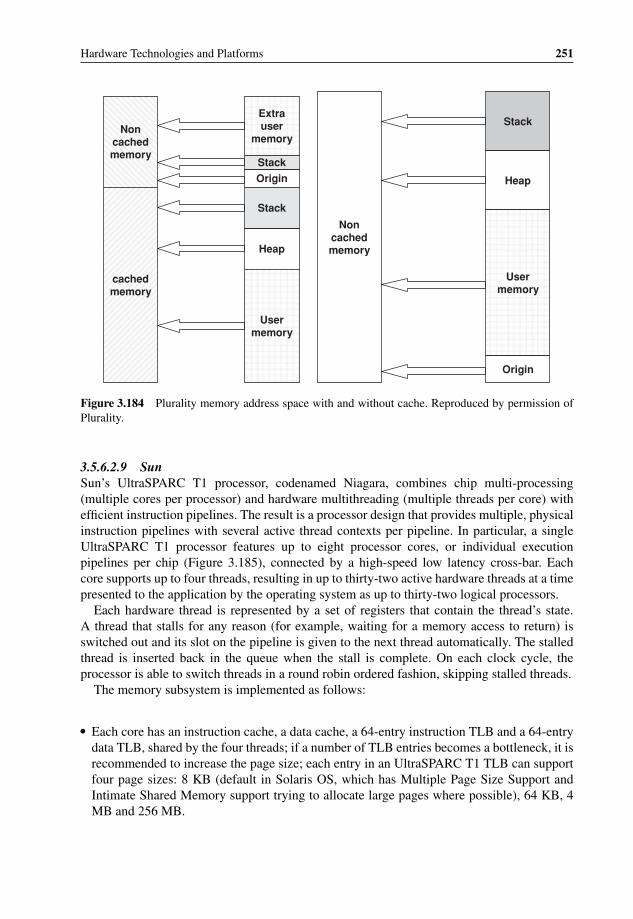
P1: OTA/XYZ P2: ABCc03 BLBK307-Bachmutsky September 2, 2010 13:12 Printer Name: Yet to Come
Hardware Technologies and Platforms 251
Noncached memory
cached memory
Extra user
memory
Stack
Origin
Stack
Heap
Usermemory
Noncached memory
Stack
Heap
User memory
Origin
Figure 3.184 Plurality memory address space with and without cache. Reproduced by permission ofPlurality.
3.5.6.2.9 SunSun’s UltraSPARC T1 processor, codenamed Niagara, combines chip multi-processing(multiple cores per processor) and hardware multithreading (multiple threads per core) withefficient instruction pipelines. The result is a processor design that provides multiple, physicalinstruction pipelines with several active thread contexts per pipeline. In particular, a singleUltraSPARC T1 processor features up to eight processor cores, or individual executionpipelines per chip (Figure 3.185), connected by a high-speed low latency cross-bar. Eachcore supports up to four threads, resulting in up to thirty-two active hardware threads at a timepresented to the application by the operating system as up to thirty-two logical processors.
Each hardware thread is represented by a set of registers that contain the thread’s state.A thread that stalls for any reason (for example, waiting for a memory access to return) isswitched out and its slot on the pipeline is given to the next thread automatically. The stalledthread is inserted back in the queue when the stall is complete. On each clock cycle, theprocessor is able to switch threads in a round robin ordered fashion, skipping stalled threads.
The memory subsystem is implemented as follows:
� Each core has an instruction cache, a data cache, a 64-entry instruction TLB and a 64-entrydata TLB, shared by the four threads; if a number of TLB entries becomes a bottleneck, it isrecommended to increase the page size; each entry in an UltraSPARC T1 TLB can supportfour page sizes: 8 KB (default in Solaris OS, which has Multiple Page Size Support andIntimate Shared Memory support trying to allocate large pages where possible), 64 KB, 4MB and 256 MB.
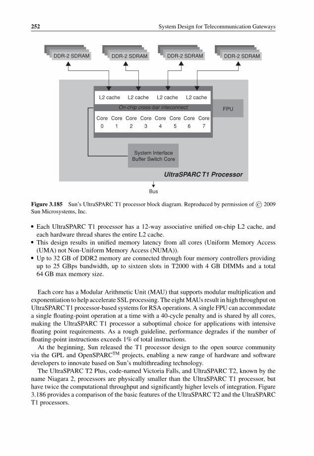
P1: OTA/XYZ P2: ABCc03 BLBK307-Bachmutsky September 2, 2010 13:12 Printer Name: Yet to Come
252 System Design for Telecommunication Gateways
DDR-2 SDRAM DDR-2 SDRAM DDR-2 SDRAMDDR-2 SDRAM
L2 cache
Core Core Core Core Core Core Core Core
FPU
System InterfaceBuffer Switch Core
Bus
UltraSPARC T1 Processor
0 1 2 3 4 5 6 7
L2 cache L2 cache
On-chip cross-bar inteconnect
L2 cache
Figure 3.185 Sun’s UltraSPARC T1 processor block diagram. Reproduced by permission of © 2009Sun Microsystems, Inc.
� Each UltraSPARC T1 processor has a 12-way associative unified on-chip L2 cache, andeach hardware thread shares the entire L2 cache.
� This design results in unified memory latency from all cores (Uniform Memory Access(UMA) not Non-Uniform Memory Access (NUMA)).
� Up to 32 GB of DDR2 memory are connected through four memory controllers providingup to 25 GBps bandwidth, up to sixteen slots in T2000 with 4 GB DIMMs and a total64 GB max memory size.
Each core has a Modular Arithmetic Unit (MAU) that supports modular multiplication andexponentiation to help accelerate SSL processing. The eight MAUs result in high throughput onUltraSPARC T1 processor-based systems for RSA operations. A single FPU can accommodatea single floating-point operation at a time with a 40-cycle penalty and is shared by all cores,making the UltraSPARC T1 processor a suboptimal choice for applications with intensivefloating point requirements. As a rough guideline, performance degrades if the number offloating-point instructions exceeds 1% of total instructions.
At the beginning, Sun released the T1 processor design to the open source communityvia the GPL and OpenSPARCTM projects, enabling a new range of hardware and softwaredevelopers to innovate based on Sun’s multithreading technology.
The UltraSPARC T2 Plus, code-named Victoria Falls, and UltraSPARC T2, known by thename Niagara 2, processors are physically smaller than the UltraSPARC T1 processor, buthave twice the computational throughput and significantly higher levels of integration. Figure3.186 provides a comparison of the basic features of the UltraSPARC T2 and the UltraSPARCT1 processors.

P1: OTA/XYZ P2: ABCc03 BLBK307-Bachmutsky September 2, 2010 13:12 Printer Name: Yet to Come
Hardware Technologies and Platforms 253
Figure 3.186 UltraSPARC T1, T2 and T2 Plus processor features. Reproduced by permission of ©2009 Sun Microsystems, Inc.
The UltraSPARC T2 and UltraSPARC T2 Plus processor designs recognize that memorylatency is truly the bottleneck to improving performance in many applications. By increasingthe number of threads supported by each core and by further increasing network bandwidth,these processors are able to provide approximately twice the throughput of the UltraSPARCT1 processor.
Each UltraSPARC T2 and UltraSPARC T2 Plus processor includes up to eight cores, witheach core able to switch between up to eight threads (sixty-four threads per processor). Inaddition, each core provides two integer execution units (EXU) with four threads sharing eachunit, eight register windows and 160 integer register file entries per thread. It allows a singleUltraSPARC core to be capable of executing two threads at a time assuming both threads areusing EXU (see Figure 3.187 for a simplified illustration).
Each core includes the instruction fetch unit with 16 KB instruction cache (32-byte lines,8-way set associative) and a 64-entry fully-associative instruction translation lookup buffer(ITLB). The memory management unit provides a hardware table walk and supports 8 KB,64 KB, 4 MB and 256 MB pages.
The UltraSPARC T2 and UltraSPARC T2 Plus processor core implements an 8-stage integerpipeline and a 12-stage floating-point pipeline. A new ‘pick’ pipeline stage has been added tochoose two threads (out of the eight possible per core) to execute each cycle. Picking withineach thread group is independent of the other and the least-recently-picked algorithm is usedto select the next thread to execute. Load/store and floating point units are shared between all

P1: OTA/XYZ P2: ABCc03 BLBK307-Bachmutsky September 2, 2010 13:12 Printer Name: Yet to Come
254 System Design for Telecommunication Gateways
Memory Latency Compute Time
Core 1
Core 2
Core 8
Thread 1
Thread 8
Thread 1
Thread 8
Thread 1
Thread 8
Figure 3.187 UltraSPARC T2 or T2 Plus processor with up to sixty-four threads. Reproduced bypermission of © 2009 Sun Microsystems, Inc.
eight threads. Only one thread from either thread group can be scheduled on such a sharedunit, per cycle.
The eight cores on the UltraSPARC T2 processor are interconnected with a non-blockingcrossbar switch (see Figure 3.188 at the top). The crossbar connects each core to the eight banksof L2 cache, and to the system interface unit for I/O. The crossbar provides approximately 300GBps of bandwidth and supports 8-byte writes from a core to a bank and 16-byte reads froma bank to a core. The system interface unit connects networking and I/O directly to memorythrough the individual cache banks. Using FB-DIMM memory supports dedicated northboundand southbound lanes to and from the caches to accelerate performance and reduce latency.This approach provides higher bandwidth than with DDR2 memory, with up to 42.4 GBpsand 21 GBps of read and write bandwidth correspondingly.
Each core provides its own fully-pipelined FPU with thirty-two floating point register fileentries per thread to enhance floating point performance of the UltraSPARC T1, as wellas a stream processing unit (SPU). SPU runs on the same core clock parallel to the coreand includes a Modular Arithmetic Unit for RSA encryption/decryption, binary and integerpolynomial functions, as well as elliptic curve cryptography and the cipher/hash unit for wire-speed hardware cryptographic acceleration of RC4, DES/3DES, AES-128/192/256, MD5,SHA-1 and SHA-256 ciphers.
The UltraSPARC T2 and UltraSPARC T2 Plus processors also provide an on-chip 8-lanePCI Express interface with 4 GBps bidirectional throughput, maximum payload size of up to
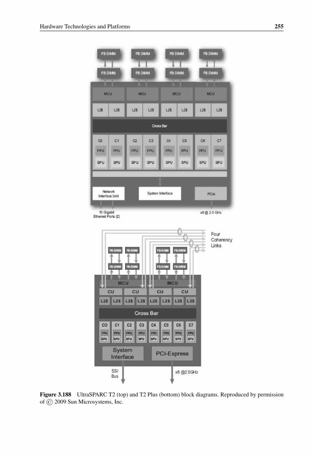
P1: OTA/XYZ P2: ABCc03 BLBK307-Bachmutsky September 2, 2010 13:12 Printer Name: Yet to Come
Hardware Technologies and Platforms 255
Figure 3.188 UltraSPARC T2 (top) and T2 Plus (bottom) block diagrams. Reproduced by permissionof © 2009 Sun Microsystems, Inc.
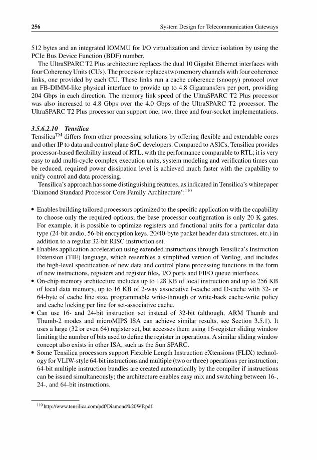
P1: OTA/XYZ P2: ABCc03 BLBK307-Bachmutsky September 2, 2010 13:12 Printer Name: Yet to Come
256 System Design for Telecommunication Gateways
512 bytes and an integrated IOMMU for I/O virtualization and device isolation by using thePCIe Bus Device Function (BDF) number.
The UltraSPARC T2 Plus architecture replaces the dual 10 Gigabit Ethernet interfaces withfour Coherency Units (CUs). The processor replaces two memory channels with four coherencelinks, one provided by each CU. These links run a cache coherence (snoopy) protocol overan FB-DIMM-like physical interface to provide up to 4.8 Gigatransfers per port, providing204 Gbps in each direction. The memory link speed of the UltraSPARC T2 Plus processorwas also increased to 4.8 Gbps over the 4.0 Gbps of the UltraSPARC T2 processor. TheUltraSPARC T2 Plus processor can support one, two, three and four-socket implementations.
3.5.6.2.10 TensilicaTensilicaTM differs from other processing solutions by offering flexible and extendable coresand other IP to data and control plane SoC developers. Compared to ASICs, Tensilica providesprocessor-based flexibility instead of RTL, with the performance comparable to RTL; it is veryeasy to add multi-cycle complex execution units, system modeling and verification times canbe reduced, required power dissipation level is achieved much faster with the capability tounify control and data processing.
Tensilica’s approach has some distinguishing features, as indicated in Tensilica’s whitepaper‘Diamond Standard Processor Core Family Architecture’:110
� Enables building tailored processors optimized to the specific application with the capabilityto choose only the required options; the base processor configuration is only 20 K gates.For example, it is possible to optimize registers and functional units for a particular datatype (24-bit audio, 56-bit encryption keys, 20/40-byte packet header data structures, etc.) inaddition to a regular 32-bit RISC instruction set.
� Enables application acceleration using extended instructions through Tensilica’s InstructionExtension (TIE) language, which resembles a simplified version of Verilog, and includesthe high-level specification of new data and control plane processing functions in the formof new instructions, registers and register files, I/O ports and FIFO queue interfaces.
� On-chip memory architecture includes up to 128 KB of local instruction and up to 256 KBof local data memory, up to 16 KB of 2-way associative I-cache and D-cache with 32- or64-byte of cache line size, programmable write-through or write-back cache-write policyand cache locking per line for set-associative cache.
� Can use 16- and 24-bit instruction set instead of 32-bit (although, ARM Thumb andThumb-2 modes and microMIPS ISA can achieve similar results, see Section 3.5.1). Ituses a large (32 or even 64) register set, but accesses them using 16-register sliding windowlimiting the number of bits used to define the register in operations. A similar sliding windowconcept also exists in other ISA, such as the Sun SPARC.
� Some Tensilica processors support Flexible Length Instruction eXtensions (FLIX) technol-ogy for VLIW-style 64-bit instructions and multiple (two or three) operations per instruction;64-bit multiple instruction bundles are created automatically by the compiler if instructionscan be issued simultaneously; the architecture enables easy mix and switching between 16-,24-, and 64-bit instructions.
110 http://www.tensilica.com/pdf/Diamond%20WP.pdf.

P1: OTA/XYZ P2: ABCc03 BLBK307-Bachmutsky September 2, 2010 13:12 Printer Name: Yet to Come
Hardware Technologies and Platforms 257
Processor Master
Processor Master
Processor Master
Processor Master
Input Device Slave
Output Device Slave
Memory Slave
Memory Slave
bus
Shared Bus
Processor Master
Processor Master
Processor Master
Input Device Slave
Output Device Slave
Memory Slave
Memory Slave
Cross-Bar
Processor Master
Processor Master
Processor Master
Processor Master
Processor Master
Processor Master
Processor Master
Processor Master
Processor Master
Global Memory
Slave
Global I/O Slave
Global I/O Slave
Routing Node
Routing Node
Routing Node
Routing Node
Routing Node
Routing Node
Routing Node
Routing Node
Routing Node
On-chip Routing Network
Global Memory
Slave
Processor Master
Processor Master
Processor Master
Processor Master
Processor Master
Dual-port Memory
Output Device Slave
Input Device Slave
bus
Queue
Queue
Queue
Application-specific
Figure 3.189 Tensilica’s range of system-interconnect topologies. Reproduced by permission ofTensilica.
� XtensaTM ISA includes compound instructions that combine the functions of multiple‘simple’ instructions into a single one. An example of such compound instruction is theextract unsigned immediate (EXTUI), which is implemented as a shift followed by an ANDwith a specified 4-bit mask. There are, however, some other ISA that provide compoundinstructions, such as compound compare and branch in SPARC and MIPS.
� Capability to add specialized instructions to reduce clock rate and lower power.� Capability of zero-overhead loops: the ability to iterate a series of instructions without a
branch at the end to loop back and without stalls caused by branch mispredictions or theneed for extra instructions to decrement and test the loop counter.
� Capability to optimize internal connectivity using point-to-point high bandwidth low latencylinks with or without dedicated queues (GPIO ports, FIFO interfaces, Lookup interfaces,etc.) in addition to regular SoC bus (see Figure 3.189). Also, system buses are configurablefor width of 32-, 64- or 128-bit, with dual load/store interface units. The design can includetheoretically 1024 interfaces with up to 1024-bit width each reaching up to 350 Tbps totalinterconnect throughput (1024 ports @ 1024 pins @ 350 MHz).
The main idea is to use the design tools (see Figure 3.190) to start from the base Xtensa core,add functional units from menu of configurable options, add register files and state registers(new data types can be added with automatic C/C++ compiler support), add load/storeinstructions up to 128-bit wide, add multi-cycle, SIMD arithmetic and logic function units,create multi-issue VLIW datapath, add custom I/O ports, queues and lookup interfaces.
One of the processors designed by Tensilica for control plane processing is the Diamond570 T (see Figure 3.191). It has 3-issue VLIW CPU, two SIMD 32x32 MACs (MultiplyACcumulator), two 32-bit I/O ports and FIFO interfaces with built-in flow-control logic.
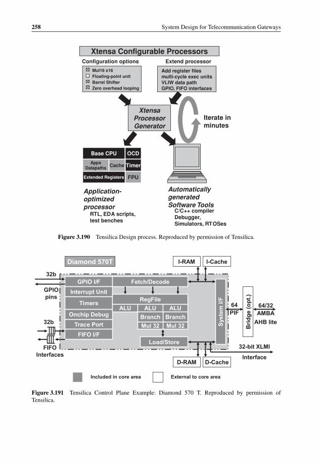
P1: OTA/XYZ P2: ABCc03 BLBK307-Bachmutsky September 2, 2010 13:12 Printer Name: Yet to Come
258 System Design for Telecommunication Gateways
Xtensa Configurable Processors
Mul16 x16Floating-point unitBarrel ShifterZero overhead looping
Add register files multi-cycle exec units VLIW data path GPIO, FIFO interfaces
Configuration options Extend processor
XtensaProcessor Generator
Iterate in minutes
Base CPU OCD
Timer
FPUExtended Registers
Apps Datapaths Cache
Base CPU OCD
Timer
FPUExtended Registers
Apps Datapaths Cache
Application-optimized processor
Automatically generated Software Tools
RTL, EDA scripts, test benches
C/C++ compiler Debugger, Simulators, RTOSes
Figure 3.190 Tensilica Design process. Reproduced by permission of Tensilica.
Diamond 570T I-RAM I-Cache
D-RAM D-Cache
GPIO I/F
Interrupt Unit
Timers
Onchip Debug
Trace Port
FIFO I/F
Fetch/Decode
RegFile
ALU ALU ALU
BranchBranch
Mul 32Mul 32
Load/Store
Sys
tem
I/F
32-bit XLMI
Interface
Bri
dg
e (o
pt.
)
64 PIF
64/32 AMBA
AHB lite
External to core areaIncluded in core area
FIFO Interfaces
32b
32b
GPIO pins
Figure 3.191 Tensilica Control Plane Example: Diamond 570 T. Reproduced by permission ofTensilica.

P1: OTA/XYZ P2: ABCc03 BLBK307-Bachmutsky September 2, 2010 13:12 Printer Name: Yet to Come
Hardware Technologies and Platforms 259
Host Interface (SPI-4.2)
Output Unit Input Unit
Network Interface (SPI-4.2)
Ext
ern
al D
DR
Mem
ory
Inte
rfac
e
Output UnitInput Unit
Shared Memory Manager
Socket Memory
Controller
Flow State Controller
Scratch Pad
Cluster Controller
1
Cluster Controller
2
Event Dispatcher
1 2 3 4 5
6 7 8 9 10Programmable Cores
Programmable Cores
Figure 3.192 Astute Networks’ Xtensa-based storage processor. Reproduced by permission of AstuteNetworks.
Based on EEMBC benchmarks, it achieved higher performance per MHz than the ARM11 orMIPS 20 K core, with smaller silicon area and power, and more interfaces. Performance ofXtensa with extensions was even more impressive.
Tensilica Xtensa programmed cores can be used to create CPUs, NPUs and even DSPs.For example, Cisco Systems has integrated 188 Xtensa cores in their Silicon Packet Processor(two per line card) used for the CSR-1 terabit router; EPSON’s printer controller chip inte-grates six heterogeneous, asymmetric, configurable Xtensa cores, legacy controller and I/O;ServerEnginesTM includes eight configurable Xtensa data processing cores with ARM pro-cessor for management purpose, dual 10 Gigabit Ethernet ports, dual Gigabit Ethernet ports,Fast Ethernet management port, PCIe 8-lane connectivity with thirty-two protected domains,and dedicated TCP/IP and crypto acceleration logic; NEC iStorage NV8200 Series has TCP/IPoffload (TOE) chip with 10 Xtensa processors; Astute Networks Pericles Network StorageProcessor (see Figure 3.192) is built using ten Xtensa cores to achieve 10 Gbps full duplexperformance running at very low 267 MHz clock with multiple storage protocols support (TCP,iSCSI, FibreChannel, SCSI, FCIP or proprietary formats) simultaneously; Juniper Networks’NetScreen-ISG 2000 Security Gateway is built using GigaScreen3 security ASIC with twoXtensa processors.
An example of the Xtensa-based packet classifier is shown in Figure 3.193. A single enginecomes with 128-bit external interfaces, four FIFO interfaces for packet streaming, I-cache,data memory for packets and most importantly the instruction extensions for packet headerparsing, packet classification based on the packet header fields and rewriting the header foregress processing path. Based on Tensilica’s calculations, with a minimum packet size of

P1: OTA/XYZ P2: ABCc03 BLBK307-Bachmutsky September 2, 2010 13:12 Printer Name: Yet to Come
260 System Design for Telecommunication Gateways
TCamQin
TaskQin
TCamQout
PacketQout
Data Memory
Packet Processing
Engine
External IRQ
sourcesOperations
Manager
Interconnect
Memory
Packet Classification Example
Packet Processing Engine
Figure 3.193 Tensilica Packet Classification Engine. Reproduced by permission of Tensilica.
84 bytes (64 B data and 20 B header), twelve engines can provide processing of 20 Gbps(10 Gbps full duplex, almost 30 Mpps) with only 400 MHz clock and the area of 21 mm2 in90 nm technology.
One partially valid argument is that conventional ASIC development is expensive and cancost $50 million and more in addition to the $1 million mask, and that Tensilica processorsare designed to minimize cost.111 This claim is logical and many vendors do use them foroptimized data processing; however, on the other hand we should not forget the concern raisedafter the publication of the huge development costs incurred by Cisco Systems during theirnew Tensilica-based NPU development.
Of course, Tensilica is not the right choice if ready-made processors can be used efficientlyand it is not expected that it will be possible to recreate other high-end processors, such asCavium Networks OCTEON/OCTEON Plus/OCTEON-II or NetLogic XLR/XLP. However,if standard off-the-shelf processors include too many unnecessary features or lack some criticalfeatures capable of improving performance, power or other parameters significantly and thedesign can accommodate the creation of its own optimized SoC, Tensilica processors canbecome a very viable solution.
3.5.6.2.11 TileraTilera©112 brings with it one of the most unique offerings, the manycore design.Its TILEPro64TM family of multicore processors features sixty-four identical processorcores interconnected with Tilera’s iMeshTM on-chip network (see Figure 3.194) for totalinterconnect throughput of more than 30 Tbps. Each core (see Figure 3.195) is a completefull-featured 32-bit in-order 3-issue processor core with 64-bit 3-way MIPS-derived VLIWISA (it also has dual 16-bit and quad 8-bit datapath SIMD operations) running at up to 866MHz core clock frequency, including integrated 16 KB I- and 8 KB D- L1 cache and 64 KBL2 cache (for total of 5.6 MB of on-chip cache) and a non-blocking switch that connects thecore into the iMesh. Each core can run a full operating system independently, or multiple coresgrouped together can run a multi-processing OS such as SMP Linux.
111 http://www.tensilica.com/white_papers/Config_Proc_Tensilica.pdf.112 http://www.tilera.com.

P1: OTA/XYZ P2: ABCc03 BLBK307-Bachmutsky September 2, 2010 13:12 Printer Name: Yet to Come
Hardware Technologies and Platforms 261
Figure 3.194 Tilera TILEPro64 Processor Block Diagram. Reproduced by permission of Tilera.
The TILEPro64 processor integrates dual 10 Gigabit Ethernet, dual Gigabit Ethernet anddual 4x PCI Express ports with a total available I/O bandwidth of 50 Gbps. The requiredmemory bandwidth is delivered using four DDR2 memory controllers. Its power consumptionis rated at up to 22 W measured with 700 MHz core clock frequency.
Using Tilera’s Dynamic Distributed Cache (DDCTM) technology, all of the chips are cachecoherent which enables programmers to run standard shared memory applications or pthreadapplications. The DDC technology uses the iMesh network to manage a distributed coherentsystem across the entire chip.
The iMesh network integrates six separate networks. Three of the networks are managed bythe hardware to manage memory traffic, cache to cache data transfer and core to core cacheinvalidation. One additional network is managed by the Operating system and drivers for I/Odevice access. The remaining two networks, the static network and user dynamic network,are available for applications requiring very fast communication between cores. The StaticNetwork (STN) is circuit-switched such as the buffered Massively Parallel Processor Array
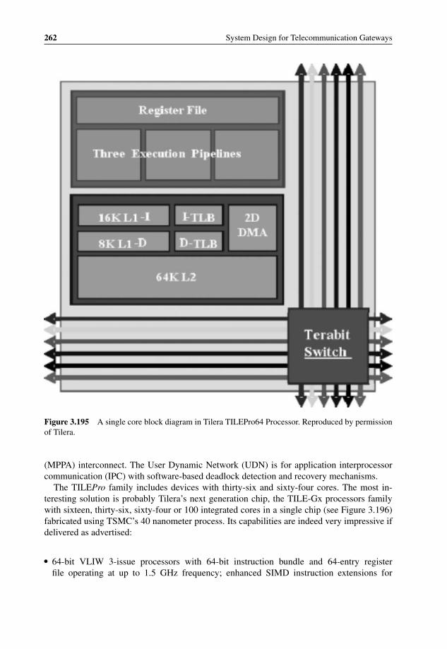
P1: OTA/XYZ P2: ABCc03 BLBK307-Bachmutsky September 2, 2010 13:12 Printer Name: Yet to Come
262 System Design for Telecommunication Gateways
Figure 3.195 A single core block diagram in Tilera TILEPro64 Processor. Reproduced by permissionof Tilera.
(MPPA) interconnect. The User Dynamic Network (UDN) is for application interprocessorcommunication (IPC) with software-based deadlock detection and recovery mechanisms.
The TILEPro family includes devices with thirty-six and sixty-four cores. The most in-teresting solution is probably Tilera’s next generation chip, the TILE-Gx processors familywith sixteen, thirty-six, sixty-four or 100 integrated cores in a single chip (see Figure 3.196)fabricated using TSMC’s 40 nanometer process. Its capabilities are indeed very impressive ifdelivered as advertised:
� 64-bit VLIW 3-issue processors with 64-bit instruction bundle and 64-entry registerfile operating at up to 1.5 GHz frequency; enhanced SIMD instruction extensions for
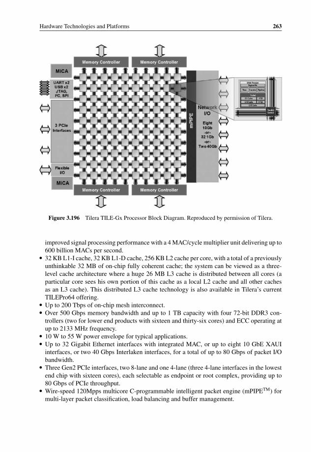
P1: OTA/XYZ P2: ABCc03 BLBK307-Bachmutsky September 2, 2010 13:12 Printer Name: Yet to Come
Hardware Technologies and Platforms 263
Figure 3.196 Tilera TILE-Gx Processor Block Diagram. Reproduced by permission of Tilera.
improved signal processing performance with a 4 MAC/cycle multiplier unit delivering up to600 billion MACs per second.
� 32 KB L1-I cache, 32 KB L1-D cache, 256 KB L2 cache per core, with a total of a previouslyunthinkable 32 MB of on-chip fully coherent cache; the system can be viewed as a three-level cache architecture where a huge 26 MB L3 cache is distributed between all cores (aparticular core sees his own portion of this cache as a local L2 cache and all other cachesas an L3 cache). This distributed L3 cache technology is also available in Tilera’s currentTILEPro64 offering.
� Up to 200 Tbps of on-chip mesh interconnect.� Over 500 Gbps memory bandwidth and up to 1 TB capacity with four 72-bit DDR3 con-
trollers (two for lower end products with sixteen and thirty-six cores) and ECC operating atup to 2133 MHz frequency.
� 10 W to 55 W power envelope for typical applications.� Up to 32 Gigabit Ethernet interfaces with integrated MAC, or up to eight 10 GbE XAUI
interfaces, or two 40 Gbps Interlaken interfaces, for a total of up to 80 Gbps of packet I/Obandwidth.
� Three Gen2 PCIe interfaces, two 8-lane and one 4-lane (three 4-lane interfaces in the lowestend chip with sixteen cores), each selectable as endpoint or root complex, providing up to80 Gbps of PCIe throughput.
� Wire-speed 120Mpps multicore C-programmable intelligent packet engine (mPIPETM) formulti-layer packet classification, load balancing and buffer management.

P1: OTA/XYZ P2: ABCc03 BLBK307-Bachmutsky September 2, 2010 13:12 Printer Name: Yet to Come
264 System Design for Telecommunication Gateways
� On-chip hardware encryption and compression Multistream iMesh Crypto Accelerator(MiCATM) enabling encryption, hashing and public key operations at speeds of up to40 Gbps and 50 000 RSA handshakes per second, and up to 20 Gbps full duplex com-pression processing.
3.5.6.2.12 Other Multicore ProcessorsThere are a number of ‘different’ solutions which cannot be regarded as the leading ones, butwhich are worth mentioning for their unique architectures.
One of them is XS1 from XMOS. The XMOS multicore architecture includesgeneral purpose cores (programmed using the C language; XMOS has developed an ex-tension called XC, which includes I/O, multicore and precision timing capabilities), eachwith its own memory and I/O system, combined on a single chip. A high-performanceswitch supports inter-core communication and inter-chip XMOS links enable multi-chip sys-tems. Any thread can communicate with any other thread in the system using single-cyclecommunication instructions. The system switches can route short packets or streamed dataefficiently.
The first product based on the XMOS architecture is XS1-G4 (see Figure 3.197). It includesfour 32-bit processing XCores; each integrates eight threads (with guaranteed hard real-timeperformance regardless of the state of other threads) and sixteen dedicated registers per thread,event-driven thread scheduler, ten timers that measure time relative to a 100 MHz referenceclock, six clock blocks, seven synchronizers, and four locks; 64 KB memory. Sixty-four I/Opins grouped into logical ports of width 1, 4, 8, 16 and 32 bits, each configurable for input,output or bidirectional, input and output operations can be timed to a local clock or an externallyprovided clock; sixteen XMOS links with 400 Mbps throughput each; JTAG debugging port;8 KBytes of OTP memory for application boot code and security keys; integer and fixed pointoperations provide DSP and cryptographic functions. Each XCore is connected to a switchwith four links, each supporting throughput of 800 Mbps.
Another interesting technology has come from the Institute of Computing Technology inChina. The first processor, called Loongson, was launched in 2001, followed by the 32-bitGodson-1 in 2002, three 64-bit Godson-2 models in 2003, 2004 and 2006 (each tripling theperformance of the previous one), while the forthcoming Godson-3 low power processorintroduces the integration of four (10 W) to eight cores (20 W) with 1 GHz clock. Theprocessor comes with 64/64 KB of L1 I-cache and D-cache and 4 MB of L2 cache. All currentimplementations are in the area of general computing (low-cost sub-notebooks and netbooks),but low power, low cost and high integration (contains both north and south bridges internally)can enable it to compete with other processors in the embedded market. The architecture waspresented at the HotChips conference at Stanford University in 2008 and more informationabout the core can be found in [GODSON].
The uniqueness of this technology is that the core is based on MIPS64 ISA, but integratesextra 200 instructions for x86 instructions emulation (called X86 binary translation speedup),which should provide up to 80% of ‘native’ x86 performance with the same clock.
The eight core version is even more interesting, as it introduces an architecture based onheterogeneous cores: four general purpose cores and four special cores. The architecture ofboth core types is shown in Figure 3.198.

P1: OTA/XYZ P2: ABCc03 BLBK307-Bachmutsky September 2, 2010 13:12 Printer Name: Yet to Come
Hardware Technologies and Platforms 265
Figure 3.197 XMOS XS1-G4 multicore. Reproduced by permission of XMOS.

P1: OTA/XYZ P2: ABCc03 BLBK307-Bachmutsky September 2, 2010 13:12 Printer Name: Yet to Come
266 System Design for Telecommunication Gateways
DMA+AXI Controller
XBAR
1024*64
4W4R
AXI interface
Micro-Controller
Micro-Code Store
1024*64
4W4R
1024*64
4W4R
1024*64
4W4R
1024*64
4W4R
1024*64
4W4R
1024*64
4W4R
1024*64
4W4R
Processor Interface
BTB
BHT
ITLB
ICache
FixQueue
Reorder Queue
FloatingPoint
RegisterFile
ALU1
ALU2
FPU1
FPU2
FloatQueue
CP0Queue
DCACHE
DTLB
ROQBRQ
IntegerRegister
FileAGU
Write back Bus
Commit Bus
Map Bus
missqueue
Refill Bus
imemread dmemwrite
PC
PC+16
dmemread, duncacheucqueue wtbkqueue
AXI Interface
EJTAG TAP ControllerTest Controller
JTAG InterfaceTest Interface
GS464 Architecture
Decode Bus
Branch Bus
clock, reset, int, …
Predecoder
Decoder
Register M
apper
Tag Com
pare
Figure 3.198 Godson heterogeneous cores architecture. Reproduced by permission of ICT.
The general purpose GS464 core includes the following functionalities:
� MIPS64, 200+ more instructions for X86 binary translation and media acceleration withonly 5% additional silicon area penalty.
� Four-issue superscalar out-of-order pipeline.� Two fix point units, two floating point units (each supports full pipelined double/paired-single
MAC operation), one memory unit.

P1: OTA/XYZ P2: ABCc03 BLBK307-Bachmutsky September 2, 2010 13:12 Printer Name: Yet to Come
Hardware Technologies and Platforms 267
� 64 KB I-cache with parity check and 64 KB D-cache with ECC, 4-way associative.� 64-entry fully associated TLB, 16-entry ITLB, variable page size.� Non-blocking accesses, load speculation.� Directory-based cache-coherence for SMP.
– Distributed L2 caches are addressed globally.– Each cache block has a directory entry.– Both data cache and instruction cache are recorded in the directory.
� EJTAG for debugging.� Standard 128-bit AXI interface.
Another multi-purpose core type is called GStera and is targeted at LINPACK, biologycomputation, signal processing and similar applications. It includes eight to sixteen MACs pernode, big multi-port register file and a standard 128-bit AXI interface.
Cores interconnect is based on a combination of crossbar and mesh; a single crossbarconnects four cores, L2s and four directions (see Figure 3.199).
The X1 switch has eight configurable address windows of each master port, which allowspages migration across L2 cache and memory. In the first implementation each switch instanceserves the same core type, but the architecture is flexible and allows mix and match differentcore types on the same switch; for example, P1 can be general-purpose core, and P2 can be
Xbar8x8
P0 P1 P2 P3
L2 L2 L2 L2
E
S
W
N
E
S
W
N
X1 Switch
S0
P0 P1 P2 P3
S1 S2 S3
m1 m2 m3 m4
m5s5
s1 s2 s4s3
X2 Switch
MC0
PCILPC
m0s0
DM
A C
on
troller
HT, P
CIE
X1 Switch
S0
P0 P1 P2 P3
S1 S2 S3
m1 m2 m3 m4m5s5
s1 s2 s4s3
X2 Switch
MC1
m0s0
HT, P
CIE
DM
A C
on
troller
Figure 3.199 Godson internal connectivity architecture and 8-core implementation. Reproduced bypermission of ICT.

P1: OTA/XYZ P2: ABCc03 BLBK307-Bachmutsky September 2, 2010 13:12 Printer Name: Yet to Come
268 System Design for Telecommunication Gateways
special core. The DMA engine supports pre-fetching and matrix operations. Shared L2 cache(blocks S0 to S3 in Figure 3.199) can be configured as internal RAM, DMA is capable ofaccessing internal RAM directly.
3.5.6.3 Multicore Benchmarking
There are a number of different multicore benchmarking techniques that help in comparingdifferent products from the same or different vendors:
� Testing of the mathematical fixed- and floating-point capabilities of multithreaded andmulticore processors. These are helpful when the application in mind is related to highperformance computing, scientific applications, etc. These tests have little relevance formany data plane processing tasks in the telecommunication industry, where the majority ofapplications are not mathematically bound; some do not have floating point operations atall, others have limited fixed-point multiplication and division.
� Running multiple instances of the same application with the same input data. This formof testing is better than pure mathematical operations because it allows for the inclusionof applications relevant to the telecommunication field. However, it stresses primarily theprocessor cores themselves for core and/or thread parallelism.
� Running multiple instances of the same application with different input data. This form oftesting, associated with data parallelism, puts more pressure on data caches and memoryinterfaces in addition to the cores. It provides a more realistic approach for telecommunica-tions and can be used, for example, for testing data plane processing behavior, such as VoIPsoftswitch, Layer 2 switching or IP forwarding.
� Running different independent applications with different input data to stress both instructionand data caches, especially with multithreaded cores.
� Running different related applications with different input data and intensive communicationbetween these applications. This scenario can be used for testing complex control planeimplementations or for systems with the data and control plane executing on differentcores/threads sharing the same processor.
Another dimension of all of these benchmarks exposes additional hardware blocks whichare integrated into many processors. There is no doubt that these offload modules affectthe results significantly. Benchmarks can include compression and encryption with differentpacket sizes, ACL checks, DPI processing for URLs or XML files, traffic management withingress policing, VOQs and egress shaping and much more. However, taking advantage ofthese offload modules requires considerable customization of each benchmark since everyprocessor has significant variability.
One additional requirement for the benchmark test is to minimize the probability of acci-dentally running the benchmark incorrectly or even cheating by the processor vendor in orderto show better performance for a specific test case. It is well known that vendors are willingto add hardware and software features designed to improve a particular benchmark result.
Finally, the testing results have little meaning if it is impossible to compare similar resultsfrom another vendor’s testing. For example, a popular IPv4 forwarding test for networkingapplications can show incomparable results if not carefully defined: 1) the traffic should be

P1: OTA/XYZ P2: ABCc03 BLBK307-Bachmutsky September 2, 2010 13:12 Printer Name: Yet to Come
Hardware Technologies and Platforms 269
destined to a randomly selected IP address out of the pre-defined large set of destinationIP addresses; 2) the traffic should be originated from a randomly selected IP address out ofthe pre-defined large set of source IP addresses; 3) there should be no pre-defined pattern inrunning the test, such as running the test consecutively for 64B packets, 128B packets, 256Bpackets, and so on. In other words, the packet size for the next test has to be selected randomlyfrom a set of the pre-defined packet sizes, because a recognizable benchmark test pattern canhelp to optimize some system operations including memory and buffer management, cacheoptimizations, etc.; 4) if relevant, optional parameters in the packet (IP options, fragmentation,etc.) must be selected randomly per packet; 5) software implementation must have the pre-defined set of features, such as fragmentation/reassembly, Layer 2 support features, ACLsupport and scalability, IP forwarding table size scalability, IPv6 support and more. The lastrequirement is critical, because it is impossible to compare the performance of full Layer 2and Layer 3 (IPv4 and IPv6) stacks implementation with a simplified IPv4-only forwardingsolution for small tables provided sometimes in the vendor’s reference application code. Itmeans that all mandatory implementation capabilities that can affect the results have to beidentified, verified and measured. Continuing with the example of IPv4 forwarding, it ispossible to have the forwarding path itself as a fast path optimized for performance, with allof the other features either not implemented at all or implemented in a slow path. Generallyspeaking, it can be legitimate to have implementation with functionality divided between a fastand slow path; however, the results have to present this division for comparison with anotherstack, where everything can be done, for example, in the fast path.
Unfortunately, there is no a single existing benchmark which can provide everything requiredto compare multicore processors and systems that are fit for telecommunication applications.The closest benchmark is, probably, the MultiBenchTM suite from the Embedded Micro-processor Benchmark Consortium, or EEMBC, which is designed to measure ‘the impactof parallelization and scalability across both data processing and computationally intensivetasks’,113 and that:
‘The suite’s individual benchmarks target three forms of concurrency:
◦ Data decomposition: allows multiple threads to cooperate on achieving a unified goal anddemonstrates a processor’s support for fine grain parallelism.
◦ Processing of multiple data streams: uses common code running over multiple threads anddemonstrates how well a solution can scale over scalable data inputs.
◦ Multiple workload processing: shows the scalability of a solution for general-purpose processingand demonstrates concurrency over both code and data.’
MultiBench grades systems using ‘marks’ that measure the best throughput factor, whichis the number of times per second the platform executes a particular workload, and theperformance scaling factor analysing platform scalability when more computing resources(threads, cores, frequency, etc.) are added. MultiBench includes three distinct marks includingthe MultiMark that consolidates the best throughput using workloads with only one workitem each of which uses only one worker, the ParallelMark that adds multiple workers andthe MixMark to include multiple work items. The scalability factor is frequently the most
113 http://www.eembc.org/benchmark/multi_sl.php.
P1: OTA/XYZ P2: ABCc03 BLBK307-Bachmutsky September 2, 2010 13:12 Printer Name: Yet to Come
270 System Design for Telecommunication Gateways
interesting in multicore and multithreaded processors, because it can show the efficiency ofadding threads and cores for a particular workload and the differences between approaches ofusing a lower amount of larger and more complex cores as opposed to using a larger numberof simpler and smaller cores.
MultiBench can run standard networking protocols, such as TCP/IP and IP Reassembly, tomeasure the performance and scalability of the system. It is definitely a great step forwardin benchmarking, but it has its limitations. For example, it does not include heavily alignedand unaligned data protocols (some processors have much lower performance while accessingunaligned data in the memory), other control plane protocols (mobile networks are well-knownfor having such protocols), sharing data and control planes on the same system, workloadstesting functional pipeline implementations and others.
A better tool for system developers and integrators and one that more accurately representsthe capabilities of a SoC targeted for telecommunications, is a scenario-based benchmark.To accommodate this type of testing, EEMBC has started with a benchmark that is able toevaluate a system’s ability to act as a TCP/IP server and to emulate system behavior usingrealistic TCP/IP client scenarios. The scenarios are split into compliance and performance.The compliance scenarios measure the capabilities of a system in terms of compliance tovarious standards. While it is understood that the real systems currently in the field are notfully compliant with all of the RFCs, it is important to qualify systems based on their level ofcompliance. The performance scenarios benchmarks measure the capabilities of a system interms of bandwidth and/or latency. To guard against errors or cheating, EEMBC also providescertification in order to verify full compliance with the standardized run rules.
3.5.6.4 Basic Multicore Selection Principles
Based only on the partial list of commercial multicore processor suppliers in Section 3.5.6, itis obvious that selecting the right solution is not an easy task. There are no only good or onlybad options here, all of the chips are legitimate for a particular use case. The question is oneof the best choice for the specific design. Of course, the main driver for selection is the targetapplication. Let us take as an example the article ‘Design Integrated Services Routers withMulticore Processors’ by Freescale’s Mike Hui in the 25 August 2008 issue of the ElectronicEngineering Times magazine. The author defines the required functionality of a IntegratedServices Router (ISR) to be a conglomeration of network and security functions includingrouting, firewall and NAT, IPsec VPN, intrusion detection and prevention, antivirus, contentfiltering and more. The article also assumes that the product design has to take into account afamily of products which presents significant design challenges:
� Simultaneous high performance data paths.� Low Bill-of-Material (BOM).� Low R&D costs, including short development cycle.� Performance and cost scalability for different deployment options.� Software reuse.� Third-party software use.
In general, it is possible to argue with the author about the definition of ISR, but that is not themain point here; therefore, we can accept the definition as an example of product requirements.
P1: OTA/XYZ P2: ABCc03 BLBK307-Bachmutsky September 2, 2010 13:12 Printer Name: Yet to Come
Hardware Technologies and Platforms 271
In this definition there is a need for the following: a broad functionality with IP routingand forwarding performed in legacy systems by ASICs, NPUs, FPGAs, or communicationprocessors; high-speed cryptography for IPsec VPN implemented frequently by dedicatedblades, offload chips (such as Cavium Networks Nitrox R© family of security processors114),cryptography hardware offload blocks integrated into the NPUs or CPUs (such as CaviumNetworks OCTEON, Freescale QorIQ P4080, NetLogic XLR/XLP, Netronome NFP32xxand others); and deep packet inspection requiring high performance general purpose CPU,including specifically the need for high-speed regular expression searches.
The article argues correctly that modern multicore System-on-Chip (SoC) devices arecapable of performing many or even all of the above tasks; it provides a good basic list of thechip requirements for the product:
� High performance Layer 2 and Layer 3 forwarding and filtering.� High performance DPI.� Integrated I/O.� Scalability up and down with a number of cores and their frequency.� Third party software integrated with value-adding proprietary software implementation.� Efficient cores with high instruction-per-clock counts.� No bottlenecks for system resources (buses, interconnects, low latency memory, etc.).� Large cache size.� Acceleration for regular expression with dynamic signature updates.� Acceleration for encryption and hashing.� Software development tools, including functional and cycle-accurate simulators, debugging
and performance monitoring.
Of course, it is the task of the system architect to define a comprehensive list of requirementsfor a particular application. A few additional points may be useful:
� There are many homogeneous and a few heterogeneous (IBM Cell, 8-core Godson 3)multicore processors available; the meaning of ‘heterogeneous’ here is the strict definitionwhich includes different types of processing cores in a single SoC. Rakesh Kumar andhis colleagues examine in [Heterogeneous-Kumar] policies for heterogeneous architectures.The authors describe a heterogeneous architecture, which outperforms the comparable-areahomogeneous architecture by up to 63%, and their evaluated best core assignment strategyachieves up to 31% speedup over a naive policy.
Steve Cox from Target Compiler Technologies calls for wider use of heterogeneousmulticore processors in his article ‘The Case for Heterogeneous Multi-Core SoCs’,115 wherehe discusses multi-processing SoC, or MPSoC. He says, ‘In the embedded world, however,much is known about algorithmic and computational requirements prior to designing theMPSoC. For example, in an MPSoC targeted for mobile handsets, functions such as wirelesscommunication, audio processing, video decoding, image coding, GPS triangulation, dataencryption and decryption, and other algorithms likely all reside on a single chip. Thereis significant variability in the algorithms for each different function, but each function
114 http://www.caviumnetworks.com/processor_security.html.115 http://www.chipdesignmag.com/print.php?articleId=2090?issueId=0.

P1: OTA/XYZ P2: ABCc03 BLBK307-Bachmutsky September 2, 2010 13:12 Printer Name: Yet to Come
272 System Design for Telecommunication Gateways
itself has its own unique computational sensitivities. This uniqueness combined with theopportunity to implement multiple independent (yet cooperating) processors all on one chipis what gives rise to heterogeneous MPSoCs’.
Many of the latest generation multicore processors, including those described in thisbook, have some form of hardware acceleration blocks, such as graphics engine, encryption/decryption, compression/decompression, timers, packet classification, traffic management,regular expression engine, grammar parser, etc. All of these processors can be consideredas heterogeneous processors, even when their ‘main’ CPUs are homogeneous. Therefore, inmany cases the choice today is not between homogeneous and heterogeneous, but betweendifferent levels of heterogeneous architecture. Comparison of these levels depends on thespecific application and on the core assignment algorithms used.
� The terms ‘high performance’ and ‘scalability up and down’ have to be well defined. Ifthe required performance is around 1 Gbps or less, the number of choices will be verylarge, because practically every multicore chip today is capable of achieving such a level ofperformance. Scalability up and down has to be defined as being either software compatible(it can be source code compatible and require re-compilation or binary compatible), orhardware compatible with the same package and pin-out.
� Integrated MACs are essential to save space and power, but they have to be the same type andquantity as needed for the project. For example, if the chip has integrated a single 10 GbpsXAUI interface (10 Gigabit Ethernet), but the requirement is to have ten separate GigabitEthernet ports, it does not help much, because in any case either an external MAC (if it is non-Ethernet interface, like SPI 4.2) or a switch would be required. Also, if some level of portsoversubscription is needed (in the example above it would be twelve or twenty-four separateGigabit Ethernet ports), external aggregation MAC or switch is probably unavoidable.
� Software availability is one of the most critical components of hardware selection. Ofcourse, some projects can afford massive software development from scratch, but manyothers cannot, and additional software development cost can easily outweigh any hardwarecost differences. Third party software is very important, and it has to be decided whichpart can be purchased or used from the open source projects and which part is developedin-house. For example, it is difficult to agree with proprietary forwarding and off-the-shelfapplication software, because it is usually the opposite: the forwarding path is a well-knownbroadly implemented code and it would be inefficient to ‘re-invent the wheel’ and implementit in-house again, while the application code can be a value-add and product differentiationfeature, meaning that frequently at least some part of the application is developed internally(a pure integration project consisting of building the product from ready-made software andhardware blocks is not considered in this statement). However, an extremely important pointhere is the selection of the third-party software vendor. Of course, it should be based onfeatures, price and availability, but it is preferable not to use proprietary software from thechip manufacturer, because it will be much more difficult to replace the chip in the futureif necessary. Also, third-party software should support other chips, preferably the next oneson the list of selected solutions. Another important item for consideration is not to replicatea similar solution many times across multiple third-party SW packages. For example, theselection may include data plane OS from vendor A (‘vendor’ here might also mean opensource), control plane OS from vendor B, IP data plane forwarding from vendor C, IP routingprotocols from vendor D, data plane IPsec from vendor E, control plane IKE (security keynegotiation) protocol from vendor F and hypervisor from vendor G. Each vendor will bring its

P1: OTA/XYZ P2: ABCc03 BLBK307-Bachmutsky September 2, 2010 13:12 Printer Name: Yet to Come
Hardware Technologies and Platforms 273
own messaging infrastructure (messages between multiple hypervisors, messages betweencontrol plane and data plane OS, messages between routing and forwarding, messagesbetween IKE and IPsec) and there would be a need for messaging in the value-add applicationcode to be developed internally. Without significant harmonization of all these mechanismsmaintenance and support will become a nightmare. The best thing in such a scenario wouldbe to request from every vendor support for a single preferred messaging scheme that canserve all purposes, but it is not always achievable.
� Having high instructions-per-clock count capability in the processor architecture is good,but measuring a real benefit from the feature is difficult. For example, longer pipelines canbe good or bad depending on the rate of the pipeline flush in a particular application. Dual-or quad-issue core implementations and parallel pipelines are good, but a dual-issue corewill not always execute two instructions per cycle, and a quad-issue core will not alwaysexecute four instructions per cycle as suggested by the core performance estimations, so thisbrings complexity and higher cost with efficiency being sometimes at the level of 25%–50%or even lower depending on the application code and compiler (manual optimization ofthe code can improve the efficiency, but the code could become highly non-portable); forexample, some real application tests show an average of 0.75–0.9 instructions per cycleon one of dual-issue processors, which is less than 50% efficiency. All of this has to beconsidered when weighing the importance of the feature.
� Cache sizes are critical, and bigger is always the better. The division between L1/L2/L3cache sizes is important, but an even more important parameter is cache miss latency. L1cache miss latency of two clocks will provide much better results than L1 cache miss latencyof ten clocks, but the real impact depends on the application, data and cache line sizes and therate of cache misses. In a few architectures it is possible to hide at least some of that latencyby pre-fetching the cache content ahead of time, which is sometimes done by compilers,but frequently requires manual optimization to find the best place for adding a pre-fetchinstruction and development tools have to be able to assist in the optimization. Anotherimportant item in comparing cache implementation is the principle of cache sharing. Cachecan be dedicated for every core, or shared between a few cores, or shared between all cores.In a shared cache it is important to consider the sharing algorithm, which can vary fromstatic configuration of the cache size per core to fully dynamic cache usage with a minimalcommitment per core. In some implementations cache can be used as a generic scratchpadmemory which is useful for a variety of applications. In other architectures the cache isdistributed (with the capability of having one or multiple copies of the cached content) whenthe cache of another core can be accessed from any core with potentially higher latency.In any sharing architecture it is important to compare the cache size per core or hardwarethread. Associativity of the cache is also an important parameter. Cache can be frontside(between a processor and memory, runs at the memory access bus clock rate) or backside(connected to a processor with an independent bus and can be clocked higher than memory).For more information, see the whitepaper ‘A Cache Primer’ by Paul Genua.116 It is alwaysgood to remember that cache is a significant part of the entire multicore chip, and thereforeincreased cache complexity and size usually increases the chip size and correspondingly thechip price.
116 http://www.freescale.com/files/32bit/doc/app_note/AN2663.pdf.

P1: OTA/XYZ P2: ABCc03 BLBK307-Bachmutsky September 2, 2010 13:12 Printer Name: Yet to Come
274 System Design for Telecommunication Gateways
� Semiconductor manufacturing technology could become an additional reference point. Forexample, if one vendor can achieve similar functionality and performance using 90 nmprocess compared to another vendor using 65 nm process, the former could be a betterchoice, because of lower manufacturing risk for older and more established technology andalso because there could be more improvements by just moving to 65 nm technology atsome point in the future without any changes. For the development of the next generation ofchip, such a difference could mean lower or higher risk to deliver the chip in the first spin.
� It is important to consider the vendor’s experience in a particular area. It is rare that the firstgeneration of devices is perfect, so the 2nd and further generations could be an indicationof a more stable and cleaner architecture that incorporates previous bug fixes, solves criticalarchitecture limitations and integrates many customer feedbacks. On the other hand, the 10thor 15th generation could actually bring an additional overhead if full backwards compatibilityto the first generation is maintained.
� Hardware acceleration engines are important, but the question that every system designershould ask is whether it is required on-chip. Of course, it is always good to have everythingon-chip as a single SoC. However, not all components of such SoCs are always the best: SoCwith the best RegEx offload engine might have not the best performing cores or lower numberof cores than another SoC without regular expression functionality. In the end, the system iswhat really matters. If the total system will be better with multiple components as opposedto a single SoC, the option should be considered seriously taking, of course, into accountadditional space, power, reliability and software complexity. In addition, the implementationof the acceleration engine is critical for the correct decision to be made. For example, somecryptography accelerators are implemented through additional CPU instructions, so everycore has its own ‘private’ crypto engine. Other cryptography accelerators are implemented asa shared internal resource accessible through a common bus by all cores. The first scheme willbe much more efficient for the encrypting/decrypting of small packets, because it producesresults with lower latency. The second scheme can be more efficient for bulk encryption,especially if the software is built in a way that the core can continue to perform some workwhile waiting for encryption/decryption results. Regular expression engines can be built inmany ways. They can be based on DFA implementation (faster search, but requires morememory, especially in patterns with nested do-not-care symbols ‘∗’), NFA implementation(slower search, but smaller pattern memory), or a hybrid approach. They can have differentnumber of supported rules, one or multiple independent rule sets; they can be stateless orstateful (search can start with one packet and continue with another one); require memoryaccess for every byte or keep packet and rules (part or all) in the internal memory affectingperformance; etc. Together with that, the main question is whether more features or moreadvanced implementation is indeed required for current or planned applications.
� Performance is always an important parameter, but there is a need to define what is moreimportant: pure performance (bits per second, packets per second, transactions per second,sessions per second, etc.), performance per $ (cost-performance efficiency), performanceper Watt (power-performance efficiency), or performance per area (performance densityefficiency). For example, a chip with 700 MHz clock can cost $500, and the same chip fromthe same vendor with 800 MHz clock costs $800. Of course, the latter has higher absoluteperformance, but the former is much more cost-performance efficient. Power-performanceefficiency is critical when significant power dissipation restrictions apply, which is typicalfor embedded design. In this case, it is better to start with the estimation of power allowance
P1: OTA/XYZ P2: ABCc03 BLBK307-Bachmutsky September 2, 2010 13:12 Printer Name: Yet to Come
Hardware Technologies and Platforms 275
for multicore processor subsystem with all external chips and components for the requiredvoltages, frequencies, connectivity options and other parameters, then filter all solutions toinclude only those within the required power budget, and only then compare between them.Power dissipation restrictions can be set either by standards, such as the ATCA and AMC, orused power supply and other components, or because of cooling cost or limitations (activeor passive, air or liquid, maximum heat sink height because of the given mechanical design,etc.).
� It is critical which benchmarks are used for performance comparison between chips. It isuseless having a high FLOPS count if the application does not require a floating point.The Dhrystone benchmark would not be helpful for estimation of real-time networkingapplication performance. Singlecore benchmark would not reflect the multicore performancescalability. Performance numbers collected by different applications would be incomparable,as shown in Section 3.5.6.3.
The list above is, of course, only partial and it is difficult to create such a list for all ofthe future generations of processors. One good tool that is often used by system integratorsis to request from every vendor competitive comparison information, where every vendorusually emphasizes its own strengths and ‘conveniently forgets’ the weaknesses, while takingthe opposite view for competitors. Combining such comparisons from all vendors helps tounderstand all of the critical strengths and weaknesses.
3.5.7 Graphic Processors
It might seem a little strange to describe graphic processors (GPU) in a book about telecom-munication platforms, but there are compelling reasons for doing so. First of all, GPUs areactually massive multicore processing engines. NVIDIA Chief Scientist David Kirk claimedduring the IEEE Hot Chips conference at Stanford University in 2005 that GPUs are actuallymore powerful than Intel and AMD general purpose multicore processors. He added that theGeForce graphics chip in the Sony Playstation 3 gaming platform is more powerful in termsof floating point operations than its main IBM Cell processor. There is a term created forGPUs when they are used for high performance computational tasks – general purpose GPUs(GPGPU). The leading GPU vendors – Intel, NVIDIA and AMD – are investing in researchand products for GPGPU. It definitely helps that GPU performance increase is way aboveMoore’s Law reaching 1000x per decade without any sign of slowing down.
3.5.7.1 Are GPUs only for Graphics?
As stated correctly by Mike Houston from Stanford University,117 CPUs are excellent for taskparallelism, while GPUs are excellent for data parallelism.
J.D.Owens from UC Davis and colleagues described the GPGPU solutions in their IEEEproceedings [GPU-Owens]. Their statement is very clear and bullish about the GPGPU: ‘Themodern GPU is not only a powerful graphics engine, but also a highly parallel programmableprocessor featuring peak arithmetic and memory width that substantially outpaces its CPU
117 http://www-graphics.stanford.edu/∼mhouston/public_talks/R520-mhouston.pdf.
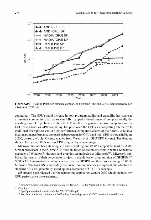
P1: OTA/XYZ P2: ABCc03 BLBK307-Bachmutsky September 2, 2010 13:12 Printer Name: Yet to Come
276 System Design for Telecommunication Gateways
Figure 3.200 Floating Point Performance comparison between GPUs and CPUs. Reproduced by per-mission of UC Davis.
counterpart. The GPU’s rapid increase in both programmability and capability has spawneda research community that has successfully mapped a broad range of computationally de-manding, complex problems to the GPU. This effort in general-purpose computing on theGPU, also known as GPU computing, has positioned the GPU as a compelling alternative totraditional microprocessors in high-performance computer systems of the future’. A relativefloating point performance comparison between major GPUs and Intel CPU is shown in Figure3.200, courtesy of John Owens, adapted from Owens et al. [GPU-CPU-Owens]. The diagramshows clearly that GPUs surpass CPU progress by a huge margin.
Microsoft has not been standing still and is working on GPGPU support (at least for AMDStream processor) in their DirectX 11 version, based on statements from Anantha Kancherla,manager of Windows R© desktop and graphics technologies at Microsoft118. Microsoft pub-lished the results of their Accelerator project to enable easier programming of GPGPUs.119
SIGGRAPH international conferences also discuss GPGPU and their programming.120 WhileMicrosoft Windows OS is not widely used in telecommunications equipment, the adoption ofstandard APIs will potentially speed up the acceptance of GPGPUs concepts.
SiSoftware have released their benchmarking application Sandra 2009 which includes rawGPU performance measurements.
118 http://www.news.softpedia.com/news/Microsoft-DirectX-11-at-the-Vanguard-of-the-GPGPU-Revolution-91539.shtml.
119 ftp://ftp.research.microsoft.com/pub/tr/TR-2005–184.pdf.120 See, for example, the conference in 2007 at http://www.siggraph.org/s2007/attendees/courses/24.html.

P1: OTA/XYZ P2: ABCc03 BLBK307-Bachmutsky September 2, 2010 13:12 Printer Name: Yet to Come
Hardware Technologies and Platforms 277
The University of Maryland is sponsoring annual awards for GPGPU programming.121 Manyuniversities have added classes related to GPGPU concepts. There is in general significantacademic research in this field.122
There are also, however, voices raising concerns. For example, Anwar Ghuloum ofIntel’s Microprocessor Technology Lab analysed in his blog three major technical issueswith GPGPUs—the programming model, system bottlenecks and the architecture123.
While the main markets for GPU-based processing are molecular dynamics, life sciences,seismic exploration, financial analysis, drug research, weather modeling and similar, thetelecommunications market can use it efficiently as a DSP replacement for audio/video en-coding, decoding and transcoding, as well as a generic signal processing for wireless. It canbe efficient for database search acceleration (see, for example [GPU-Database] with conceptsapplicable for high-performance network lookups), high-performance pattern matching co-processor and high-throughput processing applications. Ngarua Technologies Ltd from NewZealand claims that they have already achieved 40 Gbps packet processing on GPU withan impressive lead in performance over other multicore processors:124 AMD HD4850 with800 cores running proprietary software at 625 MHz frequency achieved a performance of76.2 Mpps of IPv4 prefix lookup with 1 million random 8-bit to 32-bit prefixes, while thedistant second place from all tested devices was Sun UltraSPARC T2 with sixty-four threadsrunning at 1.4 GHz and achieving for the same application only one tenth of the GPU perfor-mance with 7.5 Mpps.
There are also, however, challenges in using GPUs for packet processing. As David Pat-terson, Director of Parallel Computing Research Laboratory at UC Berkeley, described, thenext three challenges for GPUs are the relatively small size of GPU memory, inability toperform I/O operations directly to GPU memory and lack of glueless multisocket hardwareand software similar to cache-coherent multichip multicore architectures from Intel, AMD,Sun, NetLogic and some others.125 The first two challenges are based on the famous Amdahlrule, where ‘1 byte of memory and 1 byte per second of I/O are required for each instructionper second supported by a computer’. For example, based on this rule, there is a need for500 GB of RAM for 500 GFLOPS of performance (twice as much for teraflop), while theexisting systems provide usually about 4 GB or so, because of the limitations of the existingmemory technologies. Also, the Amdahl rule quoted by David Patterson provides a calculationfor diminishing returns of the processor enhancements: ‘Suppose a program spends 10% of itstime in I/O, and a new GPU makes the computation piece go 10 times faster. The speedup willjust be 1/(.1 +.9/10), or a little over 5 times faster, wasting almost half of the GPU potential.If instead the GPU could make the computation run 100 times faster, the speed up will be1/(.1 +.9/100), or a little over 9 times faster, wasting more than 90% of the GPU potential’.This second challenge presented by I/O throughput might become a critical factor in adoptingGPUs in I/O intensive telecommunication applications.
121 http://www.scriptroute.cs.umd.edu/gpucompete/.122 http://www.gpgpu.org.123 http://www.blogs.intel.com/research/2007/10/the_problem_with_gpgpu.php.124 http://www.ngarua.com/index.php/gap.125 David Patterson, ‘The Top 10 Innovations in the New NVIDIA Fermi Architecture, and the Top 3Next Chal-
lenges’, http://www.nvidia.com/content/PDF/fermi_white_papers/D.Patterson_Top10InnovationsInNVIDIAFermi.pdf.

P1: OTA/XYZ P2: ABCc03 BLBK307-Bachmutsky September 2, 2010 13:12 Printer Name: Yet to Come
278 System Design for Telecommunication Gateways
This chapter provides basic information about the commercial GPGPU solutions that areavailable. While they are not being used in telecommunication products as of now, theirpotential definitely exists, especially when one takes into account the rapid growth of GPUcapabilities. Also, one of the most significant bottlenecks in high-end networking systems isusually memory bandwidth. GPUs, on the other hand, are known to be designed for extremelyhigh memory throughput, with the fastest announced memory technology as of the time ofwriting being the GDDR5 with up to 28 GBps, which is much higher than the throughputachievable by the fastest (as of the time of writing) DDR3 with a 2200 MHz data rate. It ispossible that the first adoption of graphics technology will come directly from the memory tobe used for CPU-based system designs, especially after the significant power reduction shownby the GDDR5 technology. There is also a fast and efficient XDRTM2 technology provided byRambus, which is claimed to be more power efficient than GDDR5; however the industry hasbeen slow to adopt it.
3.5.7.2 Commercial General Purpose GPU Offerings – Advanced Micro Devices
Advanced Micro Devices’ (AMD) powerful processor, FireStreamTM 9250, is based on theRV770 GPU; it breaks the 1 TFLOPS of single-precision processing barrier with under 150 Wpower by utilizing 800 stream cores (there is also a lower power version with fewer cores). Adouble-precision floating point is also implemented in the hardware providing 200 GFLOPSof raw performance and the system comes with 1 GB of 256-bit wide GDDR3 memory. Themore powerful 9270 can achieve 240 GFLOPS of double-precision floating point and comeswith 2 GB of GDDR5 memory. In June 2008, AMD announced the release of their 4850device at about 110 W as well as the slightly higher performing 4870 device. In addition to800 cores, it uses the latest GDDR5 memory interface.
An AMD Stream processor block diagram is presented in Figure 3.201.Every Thread Processor in the above Stream Processing Unit can be presented as a 5-way
VLIW processor in the simplified block diagram shown in Figure 3.202.The Thread Processor enables the execution of five simultaneous scalar operations. For
integer or single point precision commands a single stream core is used (as it was mentionedpreviously, a single Stream Processor has up to 800 stream cores), for double precisionoperations four stream cores are combined together. The 5th T-Stream Core is a special onethat can perform transcendental operations (sine, cosine, logarithm, etc.). The Special BranchExecution Unit handles branch instructions.
The uniqueness of the architecture (and the biggest difference from general purpose CPUthreads) is that all thread processors in a single processing unit always execute the sameinstruction. For example, in Figure 3.201 there will be sixteen Thread Processors in a unit;all of which will perform the same operation. Four units are shown, which means that fourdifferent instructions can be executed simultaneously.
The Stream Processor has an efficient memory arrangement scheme. While in a generalpurpose CPU the memory layout is linear (element addresses are sequential), the StreamProcessor adds a tiled layout with a pre-defined sequence of elements, as shown in Figure3.203, which enables lower memory latency in some applications.
The AMD stream computing model is relatively simple: all user programs (called ker-nels) are running multiple instances (threads) with each instance mapped into one of thread

P1: OTA/XYZ P2: ABCc03 BLBK307-Bachmutsky September 2, 2010 13:12 Printer Name: Yet to Come
Hardware Technologies and Platforms 279
Global Data ShareInstruction Cache Constant Cache
ShaderExport
Hierarchical Z
Hierarchical Z
Tesselator
Graphics Engine
Ultra-Threaded Dispatch Processor
Rasterizer Geometry Assembler
Vertex Assembler
Rasterizer
Command Processor
L2 Cache
L2Cache
L2 Cache
L2 Cache
Memory Controller Memory Controller Memory Controller Memory Controller
Hu
b
Eyefin
ityDisp
lay Co
ntro
llersP
CI E
xpress 2.0
Bu
s Interface
UV
DC
rossF
ireXC
om
po
sitor
Lo
cal Data S
hares
L1 Textu
re Cach
es
Texture U
nits
SIM
D E
ng
ines
Figure 3.201 AMD Stream Processor (RV870) Block Diagram. Reproduced by AMD.
General-Purpose Registers
T-Stream Core
Stream Cores
BranchExecution Unit
Instruction and Control Flow
Figure 3.202 AMD Thread Processor Block Diagram. Reproduced by AMD.

P1: OTA/XYZ P2: ABCc03 BLBK307-Bachmutsky September 2, 2010 13:12 Printer Name: Yet to Come
280 System Design for Telecommunication Gateways
A B FEC D HGI J NMK L PO
Logical
Physical
A B C D E F G H
I J K L M N O P
Figure 3.203 AMD Stream Processor Memory Tiling. Reproduced by AMD.
processors; each thread writes results into its own area in the output buffer creating a regioncalled the Domain of Execution. The Stream Processor schedules all threads as they becomeavailable and kernels are executed until the entire application is completed. A simplifiedcomputing model is shown in Figure 3.204.
This hardware architecture looks very complex, which is why the AMD Stream Processorcomes with a great deal of software in the form of SDK which supports both DirectX 11and OpenCL APIs and hides most of the complexity from the programmer. The softwareecosystem includes compilers (such as the Brook+ compiler developed at Stanford Universitywith AMD open-source extensions), a device driver that is called the Compute AbstractionLayer (CAL) including support for Linux OS, a performance profiling tool called the GPUShaderAnalyzer, and multiple performance libraries for optimizing specific algorithms: ACML
T0,0 T1,0
T0,1 T1,1
T0,Ny-1 T1,Ny-1
TNx-1,0
TNx-1,1
TNx-1, Ny-1
Ti,j
Nx
Ny
Array of Threads (Domain of Execution)
Registers/Constants/Literals
Stream Core
Stream Core
Stream Core
Memory Interface
Thread Processork
Thread Proc0
Thread Prock
Thread Procn-1
Scheduler
Mem
ory
Co
ntr
olle
r
Stream Processor
Memory
Input Data
Output Data
Scheduler maps thread (i,j) into physical thread processor k
Figure 3.204 AMD Stream Computing Processing Model. Reproduced by AMD.

P1: OTA/XYZ P2: ABCc03 BLBK307-Bachmutsky September 2, 2010 13:12 Printer Name: Yet to Come
Hardware Technologies and Platforms 281
Figure 3.205 NVIDIA TeslaTM C1060 Computing Platform. Reproduced by permission of Nvidia.
for math functions, COBRA for video transcoding, some libraries from third parties (such asRapidMind), etc.
More detail, programming and optimization techniques, examples of algorithms and otheruseful information can be found in the Stream Computing Technical Overview on the AMDwebsite.126
3.5.7.3 Commercial General Purpose GPU Offerings – NVIDIA
The NVIDIA GPGPU product is called TeslaTM C1060 (see Figure 3.205); it consists of 240processing cores (there is a lower version TeslaTM C870 with 128 cores) running at 1.296 GHzclock frequency.
Tesla is programmable using a regular C language (which is called a CUDA programmingenvironment) and running potentially thousands of computing threads using the HardwareThread Execution Manager, achieving about 1 TFLOPS performance with a single-precisionand 78 GFLOPS with double-precision floating point operations. Initially, NVIDIA developedCUDA to run on its own GPUs, but the definition of CUDA language allows it to run ongeneral-purpose multicore processors. Several universities ported CUDA to run on GPCPUs.For example, John A. Stratton, Sam S. Stone, and Wen-mei W. Hwu from the University ofIllinois at Urbana-Champaign described in their paper ‘MCUDA: An Efficient Implementationof CUDA Kernels for Multi-Core CPUs’127 their newly developed MCUDA framework forGPCPUs. Currently, GPCPUs are less efficient than GPUs because of the limitations of theirArithmetic Logic Units (ALU). On the other hand, initial tests show that CUDA code onmulticore processors scaled better than even the hand-coded multicore version of the sameapplication. This is very encouraging. David Kirk, chief scientist at NVIDIA, predicts thatsoon there will be products that enable performing efficient load balancing between generalpurpose CPUs and GPUs if both types are present in the system. On the road map for CUDA
126 http://www.ati.amd.com/technology/streamcomputing/AMD_Stream_Computing_Overview.pdf.127 http://www.cs.ualberta.ca/∼amaral/LCPC08-prelim-prog/papers/Stratton.pdf.
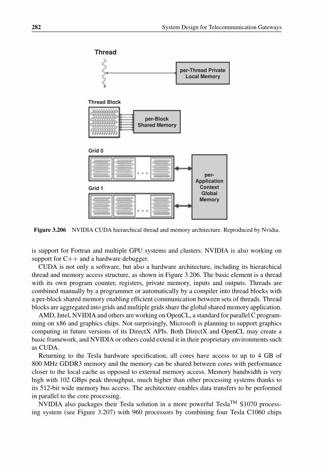
P1: OTA/XYZ P2: ABCc03 BLBK307-Bachmutsky September 2, 2010 13:12 Printer Name: Yet to Come
282 System Design for Telecommunication Gateways
Thread
Thread Block
Grid 0
Grid 1
per-Block Shared Memory
per-Thread Private Local Memory
per-Application
ContextGlobal
Memory
Figure 3.206 NVIDIA CUDA hierarchical thread and memory architecture. Reproduced by Nvidia.
is support for Fortran and multiple GPU systems and clusters. NVIDIA is also working onsupport for C++ and a hardware debugger.
CUDA is not only a software, but also a hardware architecture, including its hierarchicalthread and memory access structure, as shown in Figure 3.206. The basic element is a threadwith its own program counter, registers, private memory, inputs and outputs. Threads arecombined manually by a programmer or automatically by a compiler into thread blocks witha per-block shared memory enabling efficient communication between sets of threads. Threadblocks are aggregated into grids and multiple grids share the global shared memory application.
AMD, Intel, NVIDIA and others are working on OpenCL, a standard for parallel C program-ming on x86 and graphics chips. Not surprisingly, Microsoft is planning to support graphicscomputing in future versions of its DirectX APIs. Both DirectX and OpenCL may create abasic framework, and NVIDIA or others could extend it in their proprietary environments suchas CUDA.
Returning to the Tesla hardware specification, all cores have access to up to 4 GB of800 MHz GDDR3 memory and the memory can be shared between cores with performancecloser to the local cache as opposed to external memory access. Memory bandwidth is veryhigh with 102 GBps peak throughput, much higher than other processing systems thanks toits 512-bit wide memory bus access. The architecture enables data transfers to be performedin parallel to the core processing.
NVIDIA also packages their Tesla solution in a more powerful TeslaTM S1070 process-ing system (see Figure 3.207) with 960 processors by combining four Tesla C1060 chips

P1: OTA/XYZ P2: ABCc03 BLBK307-Bachmutsky September 2, 2010 13:12 Printer Name: Yet to Come
Hardware Technologies and Platforms 283
Tesla GPU
Tesla GPU
Tesla GPU Tesla
GPU
Power Supply
Thermal Management
System Monitoring
4.0 GB DRAM
4.0 GB DRAM
4.0 GB DRAM
4.0 GB DRAM
NVIDIA Switch
NVIDIA Switch
PCIe x16
PCI-Express Cables to Host System(s)
Figure 3.207 NVIDIA Tesla S1070 1U Computing System Architecture. Reproduced by Nvidia.
into a compact 1U rack-mount chassis (talk about core density!) with a total of 4 TFLOPSperformance and dual PCI-Express 2.0 interfaces for up to 12.8 GBps external interfaces.
The major weak point of the GPU-based solution is its power requirements – a single TeslaC1060 board needs about 200 W of peak power (160 W typical) with an active fan for cooling.Even the lower-end Tesla C870 requires 170 W peak (120 W typical) power. However, forapplications which can afford such a power, it can be an attractive option.
For those interested in more detailed information about NVIDIA GPGPUs, an excellentreview article has been published by David Kanter of Real World Technologies.128 There isalso a good overview article ‘NVIDIA Unleashes Cuda Attacks Parallel-compute Challenge’published by Colin Holland in the April 2008 issue of the Electronic Engineering Times.129
One of the most recent, as of the time of writing, NVIDIA announcement was the newFermi architecture. The first Fermi GPU has sixteen 3rd generation Streaming Multipro-cessors (SMs), each with thirty-two CUDA cores for total of 512 CUDA cores, 64 KB ofRAM with a configurable partitioning of shared memory and an L1 cache called ParallelDataCache technology (the 64 KB memory can be configured as either 48 KB of sharedmemory with 16 KB of L1 cache, or 16 KB of shared memory with 48 KB of L1 cache), sixteenload/store units to enable data handling for up to sixteen threads per clock, four special functionunits for single-cycle transcendental instructions, such as sin/cosine/reciprocal/square rootand quadrupled in performance double precision floating point operations. To ensure massiveparallel data processing, ‘The SM schedules threads in groups of 32 parallel threads calledwarps. Each SM features two warp schedulers and two instruction dispatch units, allowingtwo warps to be issued and executed concurrently. Fermi’s dual warp scheduler selects two
128 http://www.realworldtech.com/page.cfm?ArticleID=RWT090808195242.129 http://www.eetimes.com/showArticle.jhtml?articleID=207403647.
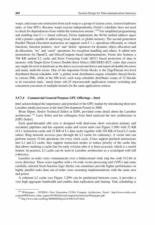
P1: OTA/XYZ P2: ABCc03 BLBK307-Bachmutsky September 2, 2010 13:12 Printer Name: Yet to Come
284 System Design for Telecommunication Gateways
warps, and issues one instruction from each warp to a group of sixteen cores, sixteen load/storeunits, or four SFUs. Because warps execute independently, Fermi’s scheduler does not needto check for dependencies from within the instruction stream’.130 For simplified programmingand enabling true C++ based software, Fermi implements the 40-bit unified address spacewith a pointer capable of addressing local, shared, or global memory. The second generationParallel Thread eXecution instruction set supports such C++ operations efficiently as virtualfunctions, function pointers, ‘new’ and ‘delete’ operators for dynamic object allocation andde-allocation, ‘try’ and ‘catch’ operations for exception handling and others. It added newinstructions for OpenCL and DirectCompute based implementations. Fermi also features a768 KB unified L2 cache and Error Correcting Code (ECC) based protection of data inmemory with Single-Error Correct Double-Error Detect (SECDED) ECC codes that correctany single bit error in hardware as the data is accessed and detect and report all double bit errorsand many multi-bit errors. One of the important Fermi blocks is the GigaThread two-leveldistributed thread scheduler with ‘a global work distribution engine schedules thread blocksto various SMs, while at the SM level, each warp scheduler distributes warps of 32 threadsto its execution units,’ much faster sub-25 microseconds application context switching andconcurrent execution of multiple kernels for the same application context.
3.5.7.4 Commercial General Purpose GPU Offerings – Intel
Intel acknowledged the importance and potential of the GPU market by introducing their newLarrabee media processor at the Intel Development Forum in 2008.
Brian Dipert, Senior Technical Editor at EDN, provided some detail about the Larrabeearchitecture.131 Larry Seiler and his colleagues from Intel analysed the new architecture in[GPU-Seiler].
Each quad-threaded x86 core is designed with dual-issue short execution primary andsecondary pipelines and has separate scalar and vector units (see Figure 3.208) with 32 KBof L1 instruction cache and 32 KB of L1 data cache together with 256 KB of local L2 cachesubset. Ring network accesses pass through the L2 cache for coherency. A vector unit canperform sixteen 32-bit operations for every clock cycle. Cores support prefetch instructionsinto L1 and L2 cache; they support instruction modes to reduce priority of the cache linethat allows marking a cache line for early eviction after it is been accessed, which is a usefulfeature. In practice, L2 cache can be used in Larrabee architecture as a scratchpad with fullcoherency.
Larrabee in-order cores communicate over a bidirectional wide ring bus with 512-bit inevery direction. These cores together with a 16-wide vector processing unit (VPU) and somecarefully selected fixed function logic blocks can sometimes provide higher performance onhighly parallel tasks than out-of-order cores assuming implementations with the same areaand power.
A coherent L2 cache (see Figure 3.209) can be partitioned between cores; it provides avery high aggregate bandwidth and enables data replication and sharing. Task scheduling is
130 ‘Whitepaper – NVIDIA’s Next Generation CUDA Compute Architecture: Fermi’, http://www.nvidia.com/content/PDF/fermi_white_papers/NVIDIAFermiComputeArchitectureWhitepaper.pdf.
131 http://www.edn.com/blog/400000040/post/1830032183.html.
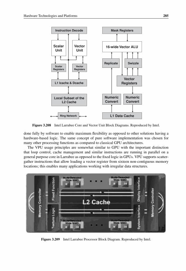
P1: OTA/XYZ P2: ABCc03 BLBK307-Bachmutsky September 2, 2010 13:12 Printer Name: Yet to Come
Hardware Technologies and Platforms 285
Instruction Decode
ScalarUnit
VectorUnit
Scalar Registers
Vector Registers
& DcacheL1 Icache
Local Subset of the L2 Cache
Ring Network
Mask Registers
16-wide Vector ALU
Replicate Swizzle
Vector Registers
Numeric Convert
Numeric Convert
L1 Data Cache
Figure 3.208 Intel Larrabee Core and Vector Unit Block Diagrams. Reproduced by Intel.
done fully by software to enable maximum flexibility as opposed to other solutions having ahardware-based logic. The same concept of pure software implementation was chosen formany other processing functions as compared to classical GPU architectures.
The VPU usage principles are somewhat similar to GPU with the important distinctionthat loop control, cache management and similar instructions are running in parallel on ageneral purpose core in Larrabee as opposed to the fixed logic in GPUs. VPU supports scatter-gather instructions that allow loading a vector register from sixteen non-contiguous memorylocations; this enables many applications working with irregular data structures.
Figure 3.209 Intel Larrabee Processor Block Diagram. Reproduced by Intel.
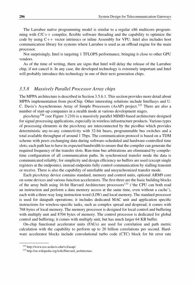
P1: OTA/XYZ P2: ABCc03 BLBK307-Bachmutsky September 2, 2010 13:12 Printer Name: Yet to Come
286 System Design for Telecommunication Gateways
The Larrabee native programming model is similar to a regular x86 multicore program-ming with C/C++ compiler, flexible software threading and the capability to optimize thecode by using C++ vector intrinsics or inline Assembly for VPU. Intel also includes hostcommunication library for systems where Larrabee is used as an offload engine for the mainprocessor.
Not surprisingly, Intel is targeting 1 TFLOPS performance, bringing it close to other GPUvendors.
As of the time of writing, there are signs that Intel will delay the release of the Larrabeechip, if not cancel it. In any case, the developed technology is extremely important and Intelwill probably introduce this technology in one of their next generation chips.
3.5.8 Massively Parallel Processor Array chips
The MPPA architecture is described in Section 3.5.6.1. This section provides more detail aboutMPPA implementation from picoChip. Other interesting solutions include Intellasys and U.C. Davis’s Asynchronous Array of Simple Processors (AsAP) project.132 There are also anumber of start-up companies in a stealth mode at various development stages.
picoArrayTM (see Figure 3.210) is a massively parallel MIMD-based architecture designedfor signal processing applications, especially in wireless infrastructure products. Various typesof processing elements in the picoArray are interconnected by the picoBus which providesdeterministic any-to-any connectivity with 32-bit buses, programmable bus switches and atotal available throughput of around 1 Tbps. The communication protocol is based on a TDMscheme with peers exchanging data during software-scheduled and hardware-controlled timeslots; each path has to have its expected bandwidth to ensure that the compiler can generate therequired frequency of the transfer slots. Run-time bus arbitrations are eliminated by compile-time configuration of all communication paths. In synchronized transfer mode the data iscommunicated reliably; for simplicity and design efficiency no buffers are used (except singleregisters at the endpoints), instead endpoints fully control communication by stalling transmitor receive. There is also the capability of unreliable and unsynchronized transfer mode.
Each picoArray device contains standard, memory and control units, optional ARM9 coreon some devices and various function accelerators. The first three are the basic building blocksof the array built using 16-bit Harvard Architecture processors133 (‘the CPU can both readan instruction and perform a data memory access at the same time, even without a cache’),each with a three-way long instruction word (LIW) and local memory. The standard processoris used for datapath operations; it includes dedicated MAC unit and application specificinstructions for wireless-specific tasks, such as complex spread and despread; it comes with768 bytes of local memory. The memory processor is designed for local control and bufferingwith multiply unit and 8704 bytes of memory. The control processor is dedicated for globalcontrol and buffering; it comes with multiply unit, but has much larger 64 KB buffer.
On-chip functional accelerator units (FAUs) are used for correlation and path metriccalculation with the capability to perform up to 20 billion correlations per second. Hard-ware accelerator blocks include convolutional turbo code (CTC) block for bit error rate
132 http://www.ece.ucdavis.edu/vcl/asap/.133 http://en.wikipedia.org/wiki/Harvard_architecture.

P1: OTA/XYZ P2: ABCc03 BLBK307-Bachmutsky September 2, 2010 13:12 Printer Name: Yet to Come
Hardware Technologies and Platforms 287
Figure 3.210 The picoChip picoArray Block Diagram. Reproduced by picoChip.
enhancements, FFT/IFFT accelerator with capability to process in hardware up to 1024 points,Viterbi accelerator, 8 Mbps Reed-Solomon block coding accelerator and encryption/decryptionengine.
Different picoChip devices provide multiple configurations of the incorporated engines.For example, the most general-purpose PC102 integrates 240 standard processors, sixty-fourmemory processors and four control processors, in addition to fourteen FAUs; PC205–10(see Figure 3.211) comes with a 273-element picoArray, 280 MHz ARM926EJ-S processorand application accelerators for FFT/IFFT, CTC, Viterbi, Reed-Solomon and AES/DES/3DEScryptography.
3.5.9 Traffic Management
Traffic management (TM) functionality and its support have already been mentioned brieflywhen different general purpose processors, network processors and switches were discussed.

P1: OTA/XYZ P2: ABCc03 BLBK307-Bachmutsky September 2, 2010 13:12 Printer Name: Yet to Come
288 System Design for Telecommunication Gateways
picoArray
JTAG debug
GPIO
ADI
Crypto R-S Viterbi CTC FFT
SDRAM interface
External bus
interface
10/100 ethernetDMA
controllerDMA
controller
JTAG debug
TCM I/D
ARM926EJ
Cache I/D
128KBSRAM
APB Bridge
UART (2) RTC Timers GPIO/SIM
Interrupt
PC202
Figure 3.211 The picoChip PC205 Block Diagram. Reproduced by picoChip.
TM can be divided into two parts, ingress and egress, as shown in the example of Altera’s10Gbps TM134 in Figure 3.212.
There are a number of important blocks. The first is classification, which is not really apart of TM, but has to be performed before any decision has been made. The classifier canbe done either externally (for example, NPU is shown in Figure 3.212), or internally in thedevice by an integrated classification module. The purpose of this classification is to identifythe flow and QoS parameters in order to map the packet into the correct queue and schedulingalgorithm. A result of external classification can be passed to the TM using an additionalencapsulation, which is proprietary in most cases and differs between TM vendors, makinghardware and software design not very portable. Of course, changing the encapsulation formatdoes not represent a major development, but it has to be taken into account.
The second important block, which is usually not part of the TM itself, is the memoryand corresponding memory related functions, such as memory controllers, caches, memory
134 http://www.altera.com/literature/wp/wp-trffc.pdf.

P1: OTA/XYZ P2: ABCc03 BLBK307-Bachmutsky September 2, 2010 13:12 Printer Name: Yet to Come
Hardware Technologies and Platforms 289
Figure 3.212 Ingress and Egress Traffic Management in Altera’s 10 Gbps TM. Reproduced by per-mission of Altera.
and buffer management, fragmentation/reassembly and DMA engines. Memory is frequentlythe most limiting factor in achieving high throughput traffic management functionality,because memory technology trails behind packet processing technology in terms of pro-cessing bandwidth. This is one of reasons why some vendors do not use an external memory atall; however, on the other hand, any internal memory will have a limited size with increasingcost and smaller buffers for efficient QoS-aware scheduling and traffic burst control. Memoryis used for three main purposes:
� As packet buffers to provide throughput of at least double the required bandwidth in orderto account for one transfer to the memory when receiving the packet and one transferfrom the memory when sending the packet out; frequently, this requires a great deal morememory throughput if the processing includes reassembly/fragmentation overheads, headerand payload access for classification, compression/decompression, encryption/decryption,etc. Packet memory can contain a number of memory pools, each with a different fixed orvariable buffer size. Fixed-size buffers are usually faster to allocate and free and easier toimplement in the hardware; in this type of solution, the incoming packets are fragmented intoa list of chunks and reassembled back when sending the packet out. One of problems withfixed-size buffers is that the last buffer in the chain can be only partially filled wasting memoryand memory bandwidth. The well-known worst case scenario is when the internal buffersize is 64 bytes, and the incoming packet size is 65 bytes, requiring 128 bytes of memory(excluding buffer management headers overhead) and bandwidth. Many implementationsenable configuration of the buffer size, more complex systems have the capability of multiplefixed buffer sizes selected by the hardware as a function of the incoming packet size andbuffer availability.

P1: OTA/XYZ P2: ABCc03 BLBK307-Bachmutsky September 2, 2010 13:12 Printer Name: Yet to Come
290 System Design for Telecommunication Gateways
� As packet descriptors for efficient internal communication ensuring that there is no need totransfer the entire packet between different TM functional entities.
� As statistics memory to count received, dropped and sent data per port, QoS, CoS, flow, etc.,depending on the system’s requirements.
The third block in relation to TM is multicast. It involves packet and/or packet descriptorreplication and enqueuing/dequeuing, different handling of unicast and multicast traffic, in-cluding separate queues, statistics and traffic management policies, as well as multicast-awarebandwidth management and congestion control.
Finally, there are two functions that are pure TM functions, queue management andscheduling. The queue manager is responsible for the enqueuing and dequeuing of packetsto/from one of queues identified by the classifier result, buffer manager and/or packetscheduler. The number of queues in the system depends on TM implementation and schedulergranularity needs and can vary from tens of queues for coarse case, such as per-port per-CoSqueue, to millions of queues for a fine-grain traffic management with per-flow queuing. Thejob of the scheduler is to ensure a fair share of total bandwidth for every queue in the system,where the level of fairness is defined by algorithms and configurations. The wrong schedulingalgorithm or incorrect configuration of scheduling parameters can cause an unnecessary packetdrop or queue starvation if the queue is not scheduled often enough. On the other hand, theentire purpose of the scheduler is to drop lower priority packets (using algorithms like TailDrop or RED/WRED) when the system or a part of the system is overloaded from either aprocessing or throughput capacity point of view.
Despite the similarity of functional blocks between ingress and egress TM, there are sig-nificant processing differences, with the most important factors being ingress TM from theexternal interfaces and toward the switch fabric and egress TM to the external interfaces.
Ingress TM can implement ingress policing and/or ingress shaping. The ingress policingalgorithm is based on two counters forming a dual leaky bucket, the Committed InformationRate (CIR) counter and the Excess Information Rate (EIR) counter (sometimes the term PeakInformation Rate (PIR) is used to reflect the absolutely maximum rate equal to a sum of CIRand EIR), filled with tokens at the configured rate with the maximum set to the correspondingmaximum burst size. The received packet consumes tokens based on its length from the CIRcounter first and it is marked as green, or compliant, if all of the tokens were available. If theCIR counter becomes empty before or in the middle of the packet, it consumes tokens from theEIR counter and in the latter case it is marked as yellow, or partially compliant. When thereare no more tokens available in both counters, the packet is marked red, or non-compliant, andin strictly enforcing implementations is dropped either immediately or at some later stage; theimplementation can allow for a non-compliant packet to pass as and when there are enoughresources to process the packet, such as where there is enough bandwidth to send the packetout.
The ingress shaping algorithm is based on the same two counters, CIR and EIR, but alsoincludes a queue with the pre-configured size. All received packets are always enqueued ifthere is a space available in the queue, otherwise they are dropped. The shaping schedulerdequeues packets against the tokens in CIR counter first marking them green and EIR counternext (if CIR counter is empty), marking them yellow.
It is much easier to implement ingress policing, but some bursty protocols, such as window-based TCP or IPsec or unpredictably bursty video streaming, might not behave well with it.

P1: OTA/XYZ P2: ABCc03 BLBK307-Bachmutsky September 2, 2010 13:12 Printer Name: Yet to Come
Hardware Technologies and Platforms 291
On the other hand, ingress shaping requires more complex implementation, but provides betterresults for some protocols and traffic patterns.
Traffic management towards the switch fabric can be similar to egress traffic managementtowards the external interfaces (described later in this chapter), or can be based on VirtualOutput Queuing (VOQ) mechanism. VOQ can be viewed as a part of the ingress trafficmanagement which means using additional ingress buffering with at least one queue perevery ingress-egress pair of ports; multiple queues per every such pair enable additional QoSawareness implementation in the switch fabric.
One of the most important issues to understand in correct traffic management design is thedefinition of ports and TM functional distribution. To explain the concept better, let us assumethat we have traffic being classified into L classes of service, a total of N line cards with Mexternal interfaces each in the system with any-to-any logical connectivity between line cardsand one switch card to which all line cards are connected physically. There are a number ofmethods of designing the system and some examples are as follows:
� There is no visibility for egress ports in the ingress line card or in the switch card. In thisarchitecture every ingress line card maintains only L queues per each other line card, sothe number of VOQs required for every line card is equal to L∗N (the ingress line card canalso be the egress line card). This approach simplifies the switch card which does not needto have any support for VOQs, but the main disadvantage is that this architecture is highlyblocking, because if one of the egress ports becomes congested, the egress line card willsend congestion control backpressure messages that will stop traffic for all ports on that linecard.
� All line cards have extensive VOQs for every destination port in the system, which bringsthe number of required queues to L∗N∗M on every line card. The switch card does not needto have any VOQs. This is a much better architecture, because it enables one to flow-controlthe traffic for a specific CoS between a particular pair of ingress-egress ports. On the otherhand, line cards require much more buffering and more queues. One ‘hidden’ advantage ofthis scheme is that the same line cards can be used in both switched and full-mesh switchlessconfigurations.
� Line cards are aware only of other line cards, not their ports, but the switch card is awareof all ports on all line cards. This scenario reduces number of queues on line cards to L∗N,and makes the switch card more complex with L∗N∗M queues. The disadvantage of thisimplementation is that in full-mesh switchless configuration the system becomes blockingand reverses to the first design described above.
� All line cards and switch cards are aware of all destination ports with L∗N∗M queues oneach of them. This is the most complex and expensive architecture, but it enables both reuseof the same line cards in switchless configurations and reuse of the same switch card withsimpler line cards (for example, some legacy blades) in the system.
In addition to the number of queues for proper TM functionality, it is important to estimatethe amount of required buffering correctly. The simplest method is to maintain enough burstbuffer based on the total available throughput. For example, one of the popular options ismaintaining the buffer large enough to store 100 msec of traffic, which would mean 1 Gb (256MB) for 10 Gbps blade and ten times that number for 100 Gbps throughput. The problem withthis calculation is that it might not be enough for some bursty applications. For instance, if

P1: OTA/XYZ P2: ABCc03 BLBK307-Bachmutsky September 2, 2010 13:12 Printer Name: Yet to Come
292 System Design for Telecommunication Gateways
the traffic consists of 1 million active flows with 10 KB burst capability for each one of them(one example is 1 million TCP sessions with 10 KB window size), the worst case scenario hasto accommodate 10 GB of the buffers. This is the reason why for some products it is better toestimate the buffering requirement based on number of concurrent active flows and their burstsize.
The required throughput calculation for each subsystem is also critical for correct systemdesign. A number of examples are presented in Figure 3.213, where the line card is assumedto include NPU or switch with an optional inline or lookaside traffic manager implementingpacket forwarding between N Gbps full duplex external interfaces and switch fabric (allinterfaces are assumed to be full duplex) together with egress traffic shaping and VOQstoward the switch fabric.
The five diagrams show different architecture options with uni- or bidirectional dotted linesrepresenting the packet flow:
(a) NPU or switch with integrated egress traffic shaping and VOQs, as well as all external andswitch fabric ports. A single logical NPU or switch is shown, but a specific implementationcan include multiple physical NPU and/or switch devices.
(b) NPU or switch with integrated traffic management and a separate lookaside traffic manager.The diagram shows NPU or switch enforcing egress shaping with TM handling the VOQs,but it also can be the opposite. This solution requires NPU/switch and TM complexes tosupport 2xN Gbps of memory throughput and additional ports on NPU or switch for TMconnectivity (total ports interconnect throughput is 3xN Gbps and total required packetprocessing capacity is also 3xN Gbps).
(c) NPU or switch without any deep packet buffering and lookaside TM with double packetbuffering capacity, because the entire ingress and egress traffic has to flow through theTM block. One important property of this architecture is the need for a quad-rate, 4xN,processing capacity in NPU or switch and a quad-rate memory throughput, because everypacket flows through them twice in every direction, to and from the TM device. There isalso a need for 4xN Gbps full duplex interface throughput on the NPU or switch and 2xNGbps full duplex interface throughput on the TM.
(d) NPU or switch without any deep packet buffering and inline TM with double packetbuffering capacity and 4xN Gbps memory throughput, because the entire ingress andegress traffic has to flow through the TM block. The difference between this scenarioand the similar one above with lookaside TM is in the device interconnect architecture,forwarding decision location and NPU/switch load. One obvious advantage is that thisarchitecture requires only a single-rate N Gbps full duplex NPU/switch packet processingcapacity and lower external ports bandwidth. The disadvantage is that the egress trafficshaping is performed before the NPU or switch, meaning that all forwarding decisionshave already been made either prior to entering the blade or by the TM itself and the NPUor switch has to just transparently pass the packets to the output ports without making anydecision and/or packet modifications.
(e) The fifth and final diagram shows the deep packet buffering distributed betweenNPU/switch and TM with pros and cons similar to the previous scenario, except thatthe memory throughput is distributed evenly, 2xN Gbps each, between the NPU/switchand the TM.
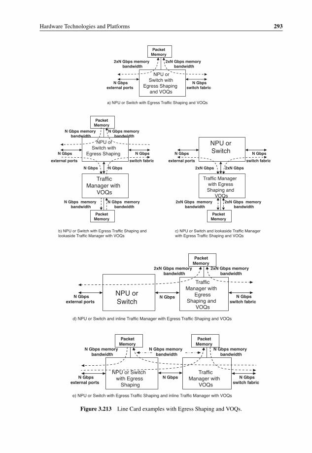
P1: OTA/XYZ P2: ABCc03 BLBK307-Bachmutsky September 2, 2010 13:12 Printer Name: Yet to Come
Hardware Technologies and Platforms 293
NPU orSwitch with
Egress Shaping and VOQs
N Gbps external ports
Packet Memory
2xN Gbps memory bandwidth
N Gbps switch fabric
NPU or Switch with
Egress ShapingN Gbps
external ports
Packet Memory
N Gbps memory bandwidth
N Gbps
switch fabric
Traffic Manager with
VOQs
N Gbps
Packet Memory
N Gbps memory bandwidth
NPU or SwitchN Gbps
external ports
Traffic Manager with Egress Shaping and
VOQs
2xN Gbps
Packet Memory
2xN Gbps memory bandwidth
N Gbps
switch fabric
a) NPU or Switch with Egress Traffic Shaping and VOQs
b) NPU or Switch with Egress Traffic Shaping and lookaside Traffic Manager with VOQs
c) NPU or Switch and lookaside Traffic Manager with Egress Traffic Shaping and VOQs
2xN Gbps memory bandwidth
N Gbps memory bandwidth
2xN GbpsN Gbps
N Gbps memory bandwidth
2xN Gbps memory bandwidth
NPU or Switch with Egress
Shaping
N Gbps external ports
Traffic Manager with
VOQs
N Gbps switch fabric
Packet Memory
NPU or Switch
N Gbps external ports
Traffic Manager with
Egress Shaping and
VOQs
N Gbps switch fabric
Packet Memory
2xN Gbps memory bandwidth
Packet Memory
N Gbps memory bandwidth
N Gbps memory bandwidth
N Gbps
N Gbps
d) NPU or Switch and inline Traffic Manager with Egress Traffic Shaping and VOQs
e) NPU or Switch with Egress Traffic Shaping and inline Traffic Manager with VOQs
2xN Gbps memory bandwidth
N Gbps memory bandwidth
Figure 3.213 Line Card examples with Egress Shaping and VOQs.
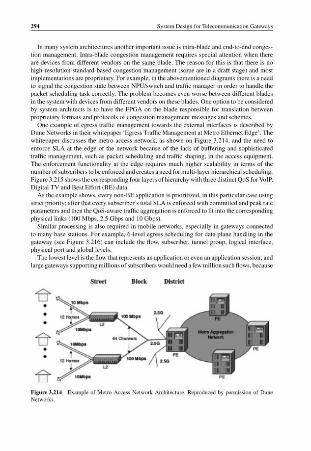
P1: OTA/XYZ P2: ABCc03 BLBK307-Bachmutsky September 2, 2010 13:12 Printer Name: Yet to Come
294 System Design for Telecommunication Gateways
In many system architectures another important issue is intra-blade and end-to-end conges-tion management. Intra-blade congestion management requires special attention when thereare devices from different vendors on the same blade. The reason for this is that there is nohigh-resolution standard-based congestion management (some are in a draft stage) and mostimplementations are proprietary. For example, in the abovementioned diagrams there is a needto signal the congestion state between NPU/switch and traffic manager in order to handle thepacket scheduling task correctly. The problem becomes even worse between different bladesin the system with devices from different vendors on these blades. One option to be consideredby system architects is to have the FPGA on the blade responsible for translation betweenproprietary formats and protocols of congestion management messages and schemes.
One example of egress traffic management towards the external interfaces is described byDune Networks in their whitepaper ‘Egress Traffic Management at Metro Ethernet Edge’. Thewhitepaper discusses the metro access network, as shown on Figure 3.214, and the need toenforce SLA at the edge of the network because of the lack of buffering and sophisticatedtraffic management, such as packet scheduling and traffic shaping, in the access equipment.The enforcement functionality at the edge requires much higher scalability in terms of thenumber of subscribers to be enforced and creates a need for multi-layer hierarchical scheduling.Figure 3.215 shows the corresponding four layers of hierarchy with three distinct QoS for VoIP,Digital TV and Best Effort (BE) data.
As the example shows, every non-BE application is prioritized, in this particular case usingstrict priority; after that every subscriber’s total SLA is enforced with committed and peak rateparameters and then the QoS-aware traffic aggregation is enforced to fit into the correspondingphysical links (100 Mbps, 2.5 Gbps and 10 Gbps).
Similar processing is also required in mobile networks, especially in gateways connectedto many base stations. For example, 6-level egress scheduling for data plane handling in thegateway (see Figure 3.216) can include the flow, subscriber, tunnel group, logical interface,physical port and global levels.
The lowest level is the flow that represents an application or even an application session; andlarge gateways supporting millions of subscribers would need a few million such flows, because
Figure 3.214 Example of Metro Access Network Architecture. Reproduced by permission of DuneNetworks.

P1: OTA/XYZ P2: ABCc03 BLBK307-Bachmutsky September 2, 2010 13:12 Printer Name: Yet to Come
Hardware Technologies and Platforms 295
Figure 3.215 Hierarchical Scheduling Example for Metro Access Network. Reproduced by permissionof Dune Networks.
subscribers frequently have multiple concurrent applications with different QoS for each oneof them. When such an application is being started, it negotiates with the network a particularQoS, which can be defined by the subscriber profile, application itself, terminal limitations,radio network limitations, mobile network equipment limitations, transport limitations, etc.For an acceptable end-user experience, this QoS has to be enforced strictly so as to providethe best possible service not only for this particular user, but also for all other users sharingthe same network resources. Enforcement includes the traffic policing, prioritization andflow shaping.

P1: OTA/XYZ P2: ABCc03 BLBK307-Bachmutsky September 2, 2010 13:12 Printer Name: Yet to Come
296 System Design for Telecommunication Gateways
Flow
Subscriber
Tunnel Group
Interface
Port
Global
x100K or x1M entries (multiple flows per subscriber)
x100K entries
x10K entries (per base station group, i.e. set of IP addresses)
x1K entries (logical interfaces, such as VLANs)
x100 entries (physical ports)
1 entry (per network element, controlled by pay-as-you-grow license)
Figure 3.216 Hierarchical Scheduling Example for a Gateway in Mobile Networks.
The second level of scheduling is the user’s subscription service level agreement (SLA)enforcement including total user traffic shaping/policing. The example does not include onefurther potential layer of prioritization between subscribers to enable preferential treatment ofgold vs. silver vs. bronze users.
The third level of scheduling refers to a tunnel group, where the tunnel represents a logicalconnection to a base station and a group represents the capability of multiple base stations to bechained behind a single physical connection, where every chained base station has a separatetunnel. This scheduling is often forgotten, but is crucial for correct traffic management. Thereason for this is that even if the immediate physical port connection of the gateway has avery high throughput, let us say 10 Gigabit Ethernet, connectivity to a base station somewheredown the road is much more limited, sometimes a few E1/T1 links, or 100 Mbps Fast Ethernet.The access network usually does not have enough buffering to sustain even short bursts of10 Gbps; therefore, the traffic has to be shaped to the required backhaul capacity in order toavoid unnecessary data discard, especially when such discard in a buffer overflow situationcan cause drop of even high priority packets.
The next two scheduling layers, logical and physical ports, are transport layers. They areenforced based on logical ports configuration, such as VLANs, and physical port load. Ofcourse, all scheduling here is also QoS-aware.
The final global layer represents the product license as purchased by the mobile operator. Forexample, an operator might purchase only 1 Gbps of data traffic license on a pay-as-you-growbasis.
An example of a commercially available pure TM device, in addition to the Altera 10 GbpsFPGA-based module described above, is Broadcom’s BCM88235/BCM88236 (BCM88235implements additional proprietary fabric interface) which combines packet buffering with up to2.4 GB of multi-channel DDR3 packet memory running at 1333 MHz, 80 Gbps traffic manage-ment supporting Virtual Output Queuing and Subscriber Queuing with integrated counters andqueue states and multilayer hierarchical traffic scheduler, four HiGig2 interfaces for connection

P1: OTA/XYZ P2: ABCc03 BLBK307-Bachmutsky September 2, 2010 13:12 Printer Name: Yet to Come
Hardware Technologies and Platforms 297
to Broadcom StrataXGS and other packet processor devices (CPUs/NPUs/FPGAs/ASICs), ahigh-speed switch fabric interface utilizing the 6.5625 Gbps SerDes technology, PCIe inter-face for management purposes and hardware-based lossless failover with auto-switchover forhighly available configurations.
3.5.10 Data Plane and Control Plane Scalability
The previous sections have discussed data and control plane separation and independentscalability. This section focuses on each plane’s scalability in the system and different productsin general.
The first important issue to remember is the need for scalability both up and down. Some-times this is obvious based on product requirements; in other cases it is hidden behind eithera lack of specific product needs or poor awareness of other products. For example, a productmight require 10–20 Gbps throughput for a data plane, but nobody thought about a much lowerstarting configuration with a ‘grow as you go’ concept for green-field operators or anothersmaller box with similar processing (it does not have to have exactly the same protocols) andonly 1–5 Gbps throughput and the capability to reuse the same hardware platform.
Hardware scalability up and down can be achieved by a number of steps:
� Scaling of the processing element frequency and/or voltage levels. This is probably theeasiest way to scale down, but in addition to some boundary limitations on both lowestand highest frequency/voltage, it requires an initial purchase or the development (in case ofcustom ASIC or FPGA) of the high-end device even when starting from the low-end.
� Scaling a number of homogeneous processing elements in a single device. It can be thenumber of cores in a multicore processor or NPU, or the number of instances in the ASICor FPGA. Scaling through instances requires efficient load balancing between them, whichcan be done using internal or external hardware, sometimes with software involvement, suchas the SMP OS with multiple threads or processes. If the processing can be parallelized,this type of scaling is usually more efficient and can achieve higher levels of scalabilitythan frequency or voltage control. Some scalability levels can be achieved without any otherhardware changes. For example, the Cavium Networks OCTEON Plus 5860 processor hasexactly the same package and pinout for any parts between four and sixteen cores. In thisexample the designer has a choice of installing a sixteen-core processor and enabling thecores as needed using only a software configuration; it is also possible to install an eight-coredevice for four to eight cores scalability in software and replace it with new sixteen-corebased hardware (a daughter board with the processor would be a good design principle inthis scenario) when ready to scale up to that level; however, the hardware change will berelatively simple and hardware design is required only once assuming that the power andcooling parameters for the sixteen-core processor are taken into account. However, evenwithout pin compatibility, such as taking a dual-core OCTEON Plus device for the sameexample, it is critical to maintain software compatibility.
� Adding on-chip or off-chip heterogeneous processing blocks. In many cases, these blocksare application-specific (classification, cryptography, compression, XML parsing, RegExprocessing, memory and buffer management, traffic management, timers, CRC/checksumcalculation and verification, hash calculation, etc.), but some implementations can be more

P1: OTA/XYZ P2: ABCc03 BLBK307-Bachmutsky September 2, 2010 13:12 Printer Name: Yet to Come
298 System Design for Telecommunication Gateways
generic, such as a companion FPGA. The idea behind this method is that a special-purposeblock can replace a number of regular processing elements.
� Scaling a number of chips on the same die. This can be an efficient way to save real estateon the blade assuming that the resulting package is not too big. Intel, for example, did itpreviously, but it works mostly when external connections are through a separate companionchipset. Many SoCs integrate all connections on-chip, such as memory controllers, net-working ports, interrupt controller, etc. With these SoCs it is difficult to integrate multiplechips on the same die, while maintaining the same performance and scalability.
� Scaling a number of chips on the same blade. This is the next logical step when thescalability of a single chip is not enough to achieve the required application goals in terms ofperformance or scalability. Such co-located chips can be tightly coupled, such as full cachecoherent interconnect supported by Intel, AMD, Sun UltraSPARC T2 Plus and NetLogicXLP, loosely coupled by their external interfaces with some level of external and/or internalload balancing, or a hybrid approach when some parts are tightly coupled and others are not,such as Cavium Networks OCTEON internal bypass for the chaining of multiple devices, andspecial proprietary interconnects allowing access to the available resources of the companionchip. Tightly coupled configurations usually have the maximum architectural scalabilitylimitations (in most cases, two to eight chips). All multichip configurations are often limitedby the total power, cooling capabilities, board space and load balancing capacities. Atthe same time, these configurations scale not only the processing elements, but also thenetworking interfaces, memory throughput and size and application-specific offload engines.
� Scalability through multiple blades in the same box. This is an obvious choice when a singleblade cannot provide, for example, the required level of performance and it is used in allmulti-bladed chassis, such as ATCA, microTCA, BladeCenter and others. Blades can bealso tightly (see Sun Enterprise T5440 in Figure 3.11) or loosely coupled. Some blades haveall of the processing elements and interfaces installed on the blade, others use horizontal orvertical daughter cards holding the interfaces (this helps with the flexibility and scalabilityof these interfaces) and the third group of designs has horizontal or vertical daughter cardsholding the processing elements, which helps to migrate easily to the new and higher capacityprocessors. In a number of chassis architectures the special blades interconnect can be alsoused for the purpose of resiliency, such as an update channel between two neighboringblades in the ATCA platform.
� Scalability through multiple chassis, which again can be tightly or loosely coupled. Tightlycoupled examples include stackable boxes with inter-chassis load balancing, logical interfacegrouping, distributed tables and policies, single management IP address, etc. Loosely coupleddeployments are similar to a traditional data centre approach with a number of networkedchassis and an external load balancing mechanism.
All of the scalability methods above should be considered by hardware and system architectsbased on focus on the the main product (and thus, the optimization point) and its downscaledand upscaled versions.
3.5.11 Redundancy for Carrier Grade Solutions
Not all telecommunication solutions are required to be a carrier grade, but those that do followstrict high availability requirements, which are frequently at least 99.999%. However, a highly
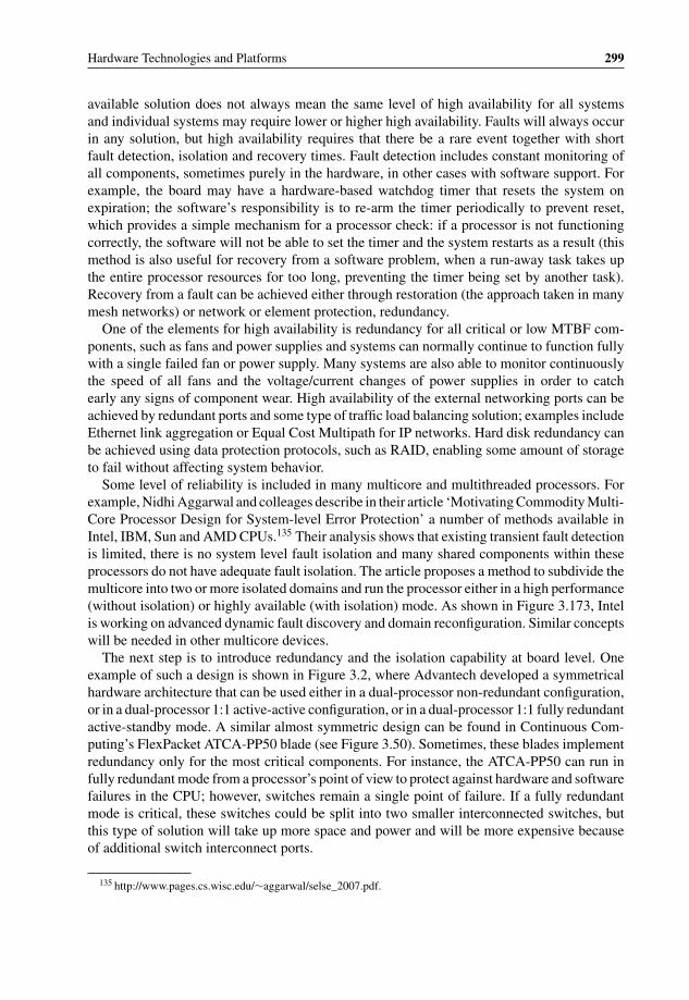
P1: OTA/XYZ P2: ABCc03 BLBK307-Bachmutsky September 2, 2010 13:12 Printer Name: Yet to Come
Hardware Technologies and Platforms 299
available solution does not always mean the same level of high availability for all systemsand individual systems may require lower or higher high availability. Faults will always occurin any solution, but high availability requires that there be a rare event together with shortfault detection, isolation and recovery times. Fault detection includes constant monitoring ofall components, sometimes purely in the hardware, in other cases with software support. Forexample, the board may have a hardware-based watchdog timer that resets the system onexpiration; the software’s responsibility is to re-arm the timer periodically to prevent reset,which provides a simple mechanism for a processor check: if a processor is not functioningcorrectly, the software will not be able to set the timer and the system restarts as a result (thismethod is also useful for recovery from a software problem, when a run-away task takes upthe entire processor resources for too long, preventing the timer being set by another task).Recovery from a fault can be achieved either through restoration (the approach taken in manymesh networks) or network or element protection, redundancy.
One of the elements for high availability is redundancy for all critical or low MTBF com-ponents, such as fans and power supplies and systems can normally continue to function fullywith a single failed fan or power supply. Many systems are also able to monitor continuouslythe speed of all fans and the voltage/current changes of power supplies in order to catchearly any signs of component wear. High availability of the external networking ports can beachieved by redundant ports and some type of traffic load balancing solution; examples includeEthernet link aggregation or Equal Cost Multipath for IP networks. Hard disk redundancy canbe achieved using data protection protocols, such as RAID, enabling some amount of storageto fail without affecting system behavior.
Some level of reliability is included in many multicore and multithreaded processors. Forexample, Nidhi Aggarwal and colleages describe in their article ‘Motivating Commodity Multi-Core Processor Design for System-level Error Protection’ a number of methods available inIntel, IBM, Sun and AMD CPUs.135 Their analysis shows that existing transient fault detectionis limited, there is no system level fault isolation and many shared components within theseprocessors do not have adequate fault isolation. The article proposes a method to subdivide themulticore into two or more isolated domains and run the processor either in a high performance(without isolation) or highly available (with isolation) mode. As shown in Figure 3.173, Intelis working on advanced dynamic fault discovery and domain reconfiguration. Similar conceptswill be needed in other multicore devices.
The next step is to introduce redundancy and the isolation capability at board level. Oneexample of such a design is shown in Figure 3.2, where Advantech developed a symmetricalhardware architecture that can be used either in a dual-processor non-redundant configuration,or in a dual-processor 1:1 active-active configuration, or in a dual-processor 1:1 fully redundantactive-standby mode. A similar almost symmetric design can be found in Continuous Com-puting’s FlexPacket ATCA-PP50 blade (see Figure 3.50). Sometimes, these blades implementredundancy only for the most critical components. For instance, the ATCA-PP50 can run infully redundant mode from a processor’s point of view to protect against hardware and softwarefailures in the CPU; however, switches remain a single point of failure. If a fully redundantmode is critical, these switches could be split into two smaller interconnected switches, butthis type of solution will take up more space and power and will be more expensive becauseof additional switch interconnect ports.
135 http://www.pages.cs.wisc.edu/∼aggarwal/selse_2007.pdf.

P1: OTA/XYZ P2: ABCc03 BLBK307-Bachmutsky September 2, 2010 13:12 Printer Name: Yet to Come
300 System Design for Telecommunication Gateways
A multi-bladed system can rely on blade redundancy instead of or in addition to intrabladeredundancy. This is a popular approach and some chassis, such as ATCA, define a specialcommunication channel between neighboring blades in order to maintain a dedicated channelfor redundancy-related information exchange (states, databases, configurations, data, etc.) in a1:1 redundant mode. This method is not limited, of course, to 1:1 redundancy and any type ofactive-active and active-standby configuration can be achieved between blades. Most of suchdesigns also support hot plug and hot swap functionality, where any blade can be added orremoved without taking the system out of service. Section 4.2.1 describes different redundancymodes in more detail from the software and the management points of view. In a multi-bladedsystem the backplane is still a single point of failure, but many backplanes are purely passivewith a very low probability of failure, achieving the required 99.999% availability.
Other architectures rely on network-based redundancy, where one network element takesover the function and/or workload of another network element in the failure or overload sce-narios. Transient network devices, such as routers and switches, can use routing protocols andspecial network designs to improve the high availability (see, for example, [HighAvailability-Iniewski]). This is not the case for products that terminate user or control data sessions, suchas servers and mobile network gateways. Servers are frequently combined into clusters with
Figure 3.217 WiMAX network diagram. Figure taken from [HighAvailability-Bachmutsky].

P1: OTA/XYZ P2: ABCc03 BLBK307-Bachmutsky September 2, 2010 13:12 Printer Name: Yet to Come
Hardware Technologies and Platforms 301
external load balancing (more complex architectures include load-balanced front-end serversto ensure connectivity, clustered back-end servers to ensure data availability and redundantswitches and networks to ensure data accessibility), but in many cases server failure detec-tion and switchover are too long (tens of seconds or more), or data replication works onlyfor a stored non-real-time data, or all sessions assigned to the failed server are lost. Thisscenario would be unacceptable for mobile gateways. While the classical design for thesesystems is stateful active-standby internal redundancy, there are also network-based schemesrelying frequently on the cooperative networking approach. One of them is proposed in[HighAvailability-Bachmutsky], which describes the main high availability terms and princi-ples and defines a solution for WiMAX deployments (see Figure 3.217) that can be applicableequally to other cases.
The idea of cooperative networking is not to try to solve all problems internally, but torequest help from the neighbors. In the WiMAX example above, other network elements,gateways or base stations can detect the gateway failure and signal the mobile subscribersto move to another gateway. The protection can be 1:1, as shown above or N+M in a moregeneric scenario.
Another example of a cooperative networking approach (also presented in [HighAvailability-Bachmutsky]) are the routing protocols that can request from neighbors the information lostas a result of the failure to speed-up the process of internal state learning to quickly recoverfull service availability in addition to system availability after the restart.
The advantage of cooperative networking is that there is much less need for complex internalsoftware and hardware redundancy implementations and simpler systems usually have lowerpower, lower cost and higher reliability. The solution is not always available, but it should begiven serious consideration if it is.

P1: OTA/XYZ P2: ABCc03 BLBK307-Bachmutsky September 2, 2010 13:12 Printer Name: Yet to Come
P1: OTA/XYZ P2: ABCc04 BLBK307-Bachmutsky September 2, 2010 13:18 Printer Name: Yet to Come
4Software Technologies andPlatforms
Every hardware solution has to come with a corresponding software package. While designersnormally check the lowest levels of the software, such as drivers and boot procedures, thischapter describes much more than that. The software below the application layer has beendivided into two major sections, the basic and extended platform, both of which are discussedwith regard to their applicability to data, control and management plane processing.
4.1 Basic Software Platform
A basic software platform includes operating system(s), networking and security stacks andmultiple low-level utilities used by the extended software platform and application modules.Different device drivers are also included in the basic software platform, but they are notdiscussed here, because all drivers are device-specific and cannot be discussed in generalterms.
4.1.1 Operating Systems
There are many different operating systems (OSs), including multiple flavours for some ofthem. There are OSs applicable mostly for control plane implementations; others can beused predominantly in data plane processing; some can be considered potentially for both. Ofcourse, not all of them are discussed here, there are just too many to choose from. Also, it is notthe aim of this book to provide detail about operating systems and their architecture and eachOS is described only in terms of its capability to support a particular hardware architectureand processing applicability efficiently.
The first OS to mention is the Solaris 10 maintained by Sun; here we concentrate on itsCMT capabilities. Systems based on UltraSPARC T2 and UltraSPARC T2 Plus processorsappear as a familiar SMP system to the Solaris OS and the applications it supports. The Solaris
System Design for Telecommunication Gateways Alexander BachmutskyC© 2011 John Wiley & Sons, Ltd
303
P1: OTA/XYZ P2: ABCc04 BLBK307-Bachmutsky September 2, 2010 13:18 Printer Name: Yet to Come
304 System Design for Telecommunication Gateways
10 OS has incorporated many features in order to improve application performance in CMTarchitectures:
� CMT awareness.The Solaris 10 OS is aware of the UltraSPARC T2 and UltraSPARC T2 Plus processorhierarchy so as to balance the load effectively across all of the the available pipelines. Eventhough it exposes each of these processors as sixty-four logical processors, the Solaris OSunderstands the correlation between cores and the threads they support and provides a fastand efficient thread implementation.
� Fine-granularity manageability and binding.For the UltraSPARC T2 and UltraSPARC T2 Plus processors, the Solaris 10 OS has theability to enable or disable individual cores and threads (logical processors). In addition,the standard Solaris OS features processor sets which are able to define a group of logicalprocessors and schedule processes or threads in them. Processes and individual threads canbe bound to either a processor or a processor set, as required or desired.
� Support for virtualized networking and I/O and accelerated cryptography.The Solaris OS contains technology to support and virtualize components and subsystemsin the UltraSPARC T2 processor, including support for on-chip 10 Gigabit Ethernet portsand PCI Express interface. As a part of high-performance network architecture, CMT-awaredevice drivers are provided so that applications running within virtualization frameworks canshare I/O and network devices effectively. Accelerated cryptography is supported throughthe Solaris Cryptographic framework.
� NUMA optimization in the Solaris OS.With memory managed by each UltraSPARC T2 Plus processor in multi-CPU systems,implementation represents a non-uniform memory access (NUMA) architecture, wherethe speed needed for a processor to access its own memory is slightly different than thatrequired to access memory managed by another processor. The Solaris OS provides MemoryPlacement Optimization (MPO) to improve the placement of memory across the entiresystem physical memory and Hierarchical Lgroup support (HLS) to distinguish between thedegrees of memory remoteness, allocating resources with the lowest possible latency forapplications.
� Solaris ZFS.The Solaris ZFS 128-bit file system is based on a transactional object model that removesmost of the traditional constraints on I/O issue order, resulting in dramatic performancegains. Solaris ZFS also provides data integrity, protecting all data with 64-bit checksumsthat detect and correct silent data corruption.
Solaris is an open-source, well-engineered OS that can provide real-time behavior withpredictable and low latency scheduling. At the same time, it has all of the required APIsand libraries to run control plane applications. Solaris OS also includes fully-featured high-performance and a low overhead virtualization solution, which is a huge plus when consideringsystem integration. On the other hand, Solaris (OS) does not support many existing cuttingedge processor architectures, so its applicability is limited.
Another well-known open-source OS is Linux, which is a Unix-type operating system widelyused in servers, desktops, telecommunication infrastructure, enterprise, consumer devices andeven end-user terminals. Linux was created by a Finnish student Linus Torvalds as a way
P1: OTA/XYZ P2: ABCc04 BLBK307-Bachmutsky September 2, 2010 13:18 Printer Name: Yet to Come
Software Technologies and Platforms 305
to implement features that were missing in the original Unix version, called Minix, thesefeatures having been defined as unnecessary by Minix owner Andrew Tanenbaum. Linux isa very popular OS and there are so many excellent resources, including books and onlineinformation, that there is no reason to describe it here. On the other hand, it makes sense tomention some of Linux’s advantages and disadvantages.
One of the greatest advantages of Linux is that it is an open source project being developedby huge community of individual developers and small and large companies. One of the biggestdisadvantages of Linux is exactly the same: it is an open source project being developed byhuge community of individual developers and small and large companies. A big plus of sucha community of developers is that features can be added, verified and deployed relativelyquickly and this can be done in parallel for many features. The first problem with the processis for small developers and system integrators trying to catch up with the latest and greatestenhancements in Linux releases, which is practically mission impossible. This is the reasonwhy many vendors started to cherry-pick some particular changes or features in the latestLinux releases and back-port them into the release used by these vendors in their currentdevelopment and deployment scenarios. An additional problem for broad Linux adoption isthat every modification has to be verified in a large set of target systems and architectures.For example, it means that if one processor vendor had introduced some kind of hardwareacceleration for some existing common code, it will not be accepted into the main distributionuntil it is tested extensively, which can be a very long process.
Today, practically every hardware manufacturer provides Linux drivers for their componentsand systems. Together with that, the problem is that Linux became very fragmented as aresult of that huge community and attempted to create more focused sub-products calledLinux distributions.1 The basic public Linux kernel is maintained by www.kernel.org, andevery addition to the source code tree is heavily policed, as mentioned above, which isabsolutely necessary in order to maintain Linux stability, but becomes a bottleneck becauseof the popularity of Linux and the large number of modifications requested by hardwareand software providers. Different distributions, such as Debian, Fedora, Ubuntu, RedHat,openSUSE, FreeBSD, Mandriva, Mint (‘improved Ubuntu’), PCLinuxOS (derivative fromMandriva), Slackware, Gentoo, CentOS (RedHat derivative), Wind River (acquired by Intel)PNE/LE, MontaVista (acquired by Cavium Networks) and many others, enable one to speed-up the process, but on the other hand they create Linux derivatives that are not always fullycompatible. For example, different component vendors could decide to provide drivers andother Linux-related software for their preferred distributions, which in many cases are notfully in sync as between these vendors. This creates a huge headache for system integrators tomanage all of these components through a single distribution and it is even more complex tomove to a different Linux distribution. This is one reason why many such integrators decide tomaintain their own private distribution in addition to the long list given above. Another reasonfor private distributions is that the abovementioned change management and policing processoften delays or rejects the implementation or integration of critical functionality for a particularproject. Applications have a high dependency on the capabilities of the operating system andthe delay in Linux modifications also affects corresponding application modifications directlyand delays the entire product release as a result.
1 See comparison of many distributions in http://en.wikipedia.org/wiki/Comparison_of_Linux_distributions.

P1: OTA/XYZ P2: ABCc04 BLBK307-Bachmutsky September 2, 2010 13:18 Printer Name: Yet to Come
306 System Design for Telecommunication Gateways
Hardware
Micro-kernel (Hard real-time kernel)
Standard Linux kernel (low priority)
RT Tasks
Non-RT Tasks
Hardware
Nano-kernel/Interrupt Dispatcher
Real-time Kernel
(high priority)
Kernel (low priority)
Kernel (low priority)
RT TasksNon-RT tasks
(user space)
Non-RT tasks
(user space)
Figure 4.1 Hard Real-time Microkernel and Nanokernel Architectures. Reproduced by Intel.
Another big disadvantage of Linux (at least for the distributions above) is that it does notsupport high-performance data plane processing and fully deterministic behavior. Determinismhas been improved significantly by Linux distributions over the last few years, but even afterall of these changes it is possible for a particular high priority thread not to be scheduled forhundreds of milliseconds and even sometimes seconds because of some Linux kernel activities.The desire to solve the problem spawned additional subsets of real-time Linux distributions,such as RTLinux and Timesys, to name but a few. Many of these implementations are basedon the microkernel approach, but a nanokernel option is also available. As shown in Figure4.1, nanokernel-based implementation enables running multiple concurrent real-time and non-real-time operating systems.
Intel have also developed their version of hard real-time Linux called Xenomai (see Figure4.2) which uses the ADEOS real-time nanokernel to handle real-time interrupt dispatching.Xenomai includes abstract RTOS core with OS resources and a capability to build and connectdifferent OS interfaces called skins to support many existing OS calls, such as POSIX, pSOS,RTAI, uITRON, VRTX, VxWorksTM and its own native API.
One possible approach for improving thread scheduling determinism is not to schedulethreads at all, which exists today in a form of thread affinity when a thread is dedicatedexclusively to run on a particular core or hardware thread. The problem today is that the Linuxkernel is still trying to perform different bookkeeping tasks, interrupts and other activities forthe core and the thread even with the affinity assigned. If this can be fixed, the thread canbecome practically a run-till-completion code similar to bare-metal simple executive operatingsystems. One example of the existing implementation similar to that which is described hereis Tilera’s Zero Overhead Linux, or ZOL.2 If the functionality is implemented by the Linuxcommunity, it would reduce the need for proprietary simple executive environments, limitingit to cases where all of the cores of the processor have to run the simple executive OS (ZOLassumes that there is at least a single core running ‘regular’ Linux scheduling tasks). Tilera isworking on providing its ZOL modifications for the open source community, but the recipient,the community, is notoriously slow in taking such type of changes and making them genericand supported by all processor architectures, because real-time data plane processing is not
2 http://www.tilera.com/pdf/ProductBrief_MDE_v3.pdf.

P1: OTA/XYZ P2: ABCc04 BLBK307-Bachmutsky September 2, 2010 13:18 Printer Name: Yet to Come
Software Technologies and Platforms 307
Hardware
ADEOS/I-pipe
HAL
Abstract RTOS Core/ real-time nucleus
interfaceLinux syscall
skinsXenomai
Kernel space apps
USER SPACE ALLOCATIONS
Figure 4.2 Intel Xenomai Architecture. Reproduced by Intel.
its highest priority and also because any change in the common scheduler code has to passrigorous verification.
There is also a scheme taking an opposite approach to thread affinity. One example of theapproach is implemented by Cavium Networks and is called ‘kernel bypass’. In this mode,the simple executive code is compiled as a regular Linux thread and runs in parallel to otherLinux threads in the user space with a high priority assigned when required. The name of themode comes from the fact that the Cavium Networks processor hardware classification enginecan deliver packets directly to the queue associated with a simple executive thread bypassingLinux kernel drivers; and the simple executive thread has a capability to access hardwareresources directly from the user space, again bypassing the kernel.
However, scheduling determinism does not mean that the OS is efficient for high-speednetworking applications that require, for example, a high-performance IPv4/IPv6 stack. Thestandard Linux stack cannot handle that task efficiently in the latest generation of multi-core and manycore processors, but there have been attempts to solve the problem. 6WINDhave improved the networking stack performance in their offerings. Another potential candi-date for enhanced implementation to be integrated in the generic Linux kernel is the Interpeaknetworking stack acquired some time ago by the Wind River (which in turn was acquired byIntel) and already running as a standard feature under the VxWorks real-time OS (RTOS) andwhich is an optional feature under Wind River Linux distribution.
This brings the discussion to different RTOS offerings,3 which are selected mostly for dataplane processing, but can also be used for control plane depending on the availability ofdifferent control plane protocols and other software modules in a particular RTOS.
Wind River VxWorks is one of the very popular RTOSs. Historically it started as an OSaround a VRTX kernel and Wind River later developed its own deterministic hard real-time multitasking kernel with preemptive and round-robin scheduling capable of running inboth SMP and AMP modes (see Section 4.3.7 for a description of these modes). VxWorksincludes an error handling framework, TIPC-based inter-process communication, distributed
3 http://en.wikipedia.org/wiki/Real-time_operating_system.

P1: OTA/XYZ P2: ABCc04 BLBK307-Bachmutsky September 2, 2010 13:18 Printer Name: Yet to Come
308 System Design for Telecommunication Gateways
messaging, POSIX interface, file system and the abovementioned IPv4/IPv6 stack. VxWorkssupports many processor architectures, including x86, MIPS, PowerPC, ARM, StrongARM,xScale and others, and it can run either on the target hardware or a proprietary VxSim simulationenvironment so as to enable development when the hardware is not available for any reasonto every developer. VxWorks supports full memory separation in order to ensure that a singleapplication failure does not affect other applications and the kernel. It is considered to be astable and reliable OS and is used in many military systems, such as UAVs and helicopters, andspacecraft, which speaks for itself. It is also used in a variety of telecommunication products,including switches, routers and wireless infrastructure.
Wind River integrates both Linux PNE/LE and VxWorks efficiently into a single systemwith a common development environment; built-in communication between these operatingsystems enables efficient information exchange between data and control plane.
A very different architecture is implemented by QNX RTOS (see [OS-QNX]), owned byHarman International since 2004, which is based on a compact and efficient microkernel withonly a basic functionality that includes scheduling (strict priority-preemptive scheduling andadaptive partition scheduling; the latter guarantees minimum CPU usage to selected groupsof threads), efficient priority-aware inter-process communication that includes activating thetarget module without additional scheduling, interrupts handling and timers, while a majorityof the software, including device drivers, is running in the user space. The architecture enablesthe easier integration of only a required functionality without touching the kernel code. Anadditional benefit of the microkernel is the relatively simple implementation of the distributedsystem called Transparent Distributed Processing. QNX supports SMP and BMP multipro-cessing modes (see Section 4.3.7). QNX released the entire source code of the OS in 2007. It ispopular in the auto industry and is also used in Cisco Systems‘ telecommunication equipment.
ENEA OSETM4 is another popular microkernel-based RTOS. Its basic version has a verysmall footprint. Similar to QNX, OSE is inherently distributed in nature. It is built around theLINX inter-process communication software (see Section 4.2.1.18 for more detail about LINX)promoting a better memory-protected separation between applications exchanging data usingLINX messages. OSE supports such processor families as ARM (ARM7, ARM9, ARM10,XScale), MIPS32, PowerPC (from Freescale, IBM and AppliedMicro), Texas Instruments’OMAP and others, including a special version, OSEck, for DSPs.
OSE Multicore Edition5 (OSE MCE) supports multicore environment by ability to run inSMP or AMP mode (see Figure 4.3), achieving a good performance for data plane applications.There is a scheduler instantiated on each core, and the core 0 has a special functionality as a‘master’ core with a set of kernel threads responsible for the management of system resources.Threads on a core never update any data that belongs to any other core.
ENEA has implemented a communication scheme and slow-fast path processing separationbetween OSE and Linux enabling optimized data and control plane co-existence in the samesystem. There is also the OSE simulation environment, OSE Soft Kernel, to provide the easierdevelopment of an environment in Linux, Windows or Solaris hosts. The distributed conceptworks for a simulation environment, where some of the software can run on real hardware
4 http://www.enea.com/Templates/Product____27035.aspx.5 http://www.enea.com/epibrowser/literature%20%28pdf%29/pdf/leadgenerating/white%20papers/whitepaper_
eneamulticore.pdf.

P1: OTA/XYZ P2: ABCc04 BLBK307-Bachmutsky September 2, 2010 13:18 Printer Name: Yet to Come
Software Technologies and Platforms 309
Core 0 Core 1 Core 2
Kernel Event Backplane
RTOSE Image
Kernel Thread 1Kernel Thread 1
Kernel Thread 2Kernel Thread 2
Kernel Thread 3Kernel Thread 3
Application Thread
Packet Application Thread
Packet Application Thread
Interrupt Service Thread
Interrupt Service Thread
Figure 4.3 The ENEA OSE MCE hybrid SMP/AMP kernel technology. Reproduced by ENEA.
and some can use a simulator, which helps to cut development time without waiting for fullhardware availability.
There are many other real-time operating systems which are not described here, includingthe extremely compact Threadx [OS-Threadx] based on picokernel architecture, and others.A comprehensive list of close to 100 existing RTOS offerings can be found in Wikipedia.6
Finally, there are the bare-metal, or simple executive, single-threaded run-till-completionOSs, implemented mostly by processor vendors. It is difficult to call such an environmentan OS, because it is in practice a library that enables access to hardware resources directly.Some examples include the Sun Netra Data Plane Software (NDPS) Suite (see Section 3.1.1.3),Cavium Networks’ Simple Executive and NetLogic’ Thin Executive. They all were introducedto maximize data plane processing performance and they do that extremely well reachingperformance levels that many other operating systems cannot match. However, they are 100%proprietary, supporting only a particular CPU architecture family and increasing the stickinessof processor selection (full dependence on a processor in both hardware and software) andthus can be recommended only when other options either do not exist or do not provide therequired performance level.
4.1.2 Networking Stacks
Operating systems usually come with their own networking stack. However, such a networkingstack is not always sufficient for every product. For example, standard Linux has extensivenetworking capabilities that are described in [OS-LinuxNetworking]. On the other hand, it is
6 http://en.wikipedia.org/wiki/List_of_real-time_operating_systems.

P1: OTA/XYZ P2: ABCc04 BLBK307-Bachmutsky September 2, 2010 13:18 Printer Name: Yet to Come
310 System Design for Telecommunication Gateways
coming normally without virtual routing support, which can be integrated from other sources,such as the open source networking project ‘Virtual Routing and Forwarding for Linux’.7
However, in addition to the lack of some critical functionality, the standard Linux networkingstack has many performance and scalability limitations.
One of the basic networking stacks is Fusion from Unicoi Systems.8 This IPv4/IPv6 dual-mode stack includes source code for TCP/IP, UDP, ICMP, ARP, RARP, TFTP, BOOTP andIGMPv2, with the list of optional protocols supported containing DHCP, DNS, FTP, IGMP,NAT, PPP/ PPPoE, RIP, RTP/RTCP, RTSP, SIP, SMTP, SNMP, SNTP and TELNET.
There are a number of available feature-rich and highly scalable commercial solutionsto be considered when the standard OS functionality and/or performance and/or scalabilitycannot satisfy product requirements. One of them is the 6WINDGateTM Networking LinuxStack from 6WIND that implements in a singlecore or multicore environment all of thekernel modules including IPv4/IPv6 stack with virtual routing, QoS management, unicast andmulticast forwarding, filtering, VLAN, Layer 2 tunneling, stateful firewall and NAT. Crypto-graphy implementation includes an asynchronous IPsec stack with Open Crypto Framework,which scales with a number of cores while removing the spinlocks and bottlenecks of theLinux kernel; IPsec performance rates can reach, for instance, 10 Gbps and more (dependingon the packet size) on Cavium Networks OCTEON or NetLogic XLS/XLR/XLP multicoreprocessors.
The 6WINDGateTM Networking Linux Stack extensive feature set can be ‘decoded’ fromthe list of published supported RFCs, which includes the following:
� IP Protocols:– IPv4 & IPv6 Stacks: IP, UDP/TCP, ICMP, IP multicast, path MTU discovery, CIDR, NAT,
ECMP, SCTP, etc.– IPv4–IPv6 Transition: 6to4, 6over4, DNS application-level gateway (ALG), Stateless
IP/ICMP Translation Algorithm (SIIT), Network Address Translation – Protocol Trans-lation (NAT-PT), Intra-Site Automatic Tunnel Addressing Protocol (ISATAP), etc.
– IPsec: IP Authentication Header (AH), IP Encapsulating Security Payload (ESP), DES,AES, MD5, SHA-1, and more.
– QoS: DiffServ, assured and expedited forwarding, a two rate three colour marker.– Header compression: Robust header compression (ROHC) for IP, UDP, RTP, ESP.
� IPv4 and IPv6 Routing:– Unicast Routing: RIPv1 and v2, RIPng, BGP-4 (communities and confederations, multi-
protocol extension, route flap, route reflection, route refresh, capabilities advertisement),IS-IS, OSPFv2 and v3 (including stab router advertisement and Not-So-Stubby Area(NSSA)), Virtual Router Redundancy Protocol (VRRP), Optimized Link State RoutingProtocol (OLSR), and more.
– Multicast Routing: Internet Group Management Protocol Version2 (IGMPv2), ProtocolIndependent Multicast-Sparse Mode (PIM-SM), Multicast Listener Discovery (MLD) v1and v2 for IPv6.
7 http://www.sourceforge.net/projects/linux-vrf/.8 http://www.unicoi.com/fusion_net/fusion_tcp_ipv4_v6_dual_mode_stack.htm.
P1: OTA/XYZ P2: ABCc04 BLBK307-Bachmutsky September 2, 2010 13:18 Printer Name: Yet to Come
Software Technologies and Platforms 311
� Connectivity:– Layer2 Transport: The Point-to-Point Protocol (PPP) for IPv4 and IPv6, PPP over Ethernet
(PPPoE), RADIUS, Point-to-Point Tunneling Protocol (PPTP), Layer Two TunnelingProtocol (L2TP).
– Address Management: Dynamic Host Configuration Protocol (DHCP) with many options,DHCPv6, DNS for IPv6.
� Mobility: Mobile IPv6, Network Mobility (NEMO) Basic Support Protocol, fast handovers.� Security: Internet Security Association and Key Management Protocol (ISAKMP), The
Internet Key Exchange (IKE), the OAKLEY Key Determination Protocol, Internet X.509Public Key Infrastructure, etc.
� Management: SNMP v2 and v3, many management information base (MIB) implementa-tions.
� Tools: FTP, TFTP, Telnet, Network Time Protocol v3, Hypertext Transfer Protocol(HTTP/1.1), HTTP over TLS, The BSD syslog Protocol (IPv4 and IPv6), The SecureShell (SSH) Protocol.
In order to sustain complex Fast Path processing on 10G ports with 64 bytes packets, a linecard can be made of two MCUs: one for TX and one for RX. The 6WINDGate software allowsseveral multicore processors to be combined in a system comprising multiple processors perline card. It provides an integrated packet distribution system and inter-multicore API thatenables the whole distributed system to be managed as one single Linux system.
In addition to a very rich feature set for the Linux environment and HA support of thosecontrol plane protocols, 6WINDGate has data plane processing implementation integratedwell with the control plane (messaging, routing-forwarding communication, IKE-IPsec, fastand slow datapath). This data plane runs independently from 6WIND’s control plane, soa system can be designed with newer protocols from 6WIND or by reusing control planeprotocols from other software companies. For example, OSPF can be from 6WIND, fromanother vendor or developed internally. All of the above can run efficiently on multipleprocessor architectures, including Intel IA, Cavium Networks OCTEON Plus and OCTEON-II,NetLogic XLS/XLR/XLP and Freescale QorIQ series (others are in development). All ofthe above are extremely important capabilities to remember when selecting the requiredbasic middleware, because a correct selection should provide easy scalability and portabilityfor a broad range of products and a changing processor landscape, while providing a pre-integration of synchronization between the control plane and the Fast Path part of the data plane.6WINDGate is definitely well-positioned to meet all of these challenges and unfortunatelyfor system integrators looking for multiple sourcing options, it is the only product that offersthe entire package of both data and control plane processing for a number of state-of-the-artmulticore processors and operating systems, including the bare-metal environment. As statedpreviously, thanks to the transparent integration of 6WIND’s control plane with the data plane,which enables reusing protocols from any software company, developers have a wide rangeof choices for their control plane software.
It is important to emphasize that the 6WINDGate not only supports these different mul-ticore architectures from the instruction set point of view, but is also heavily optimized touse their integrated hardware offload capabilities (especially rich in the Cavium Networks,NetLogic and Freescale QorIQ processors) and software APIs for the highest possible dataplane processing performance.

P1: OTA/XYZ P2: ABCc04 BLBK307-Bachmutsky September 2, 2010 13:18 Printer Name: Yet to Come
312 System Design for Telecommunication Gateways
Figure 4.4 The 6WINDGate SDS mode Architecture. Reproduced by permission of 6WIND.
6WINDGate’s SDS architecture (see Figure 4.4) has a number of useful features that fitwell into the multicore environment. A number of cores can run the data plane processing, theFast Path, in AMP mode; the number can be based on the required performance and in manynetworking applications the data plane performance scales almost linearly with a numberof cores. Other cores can run the control plane processing, the Slow Path, utilizing LinuxSMP mode. Communication between data and control plane can be done either through theshared memory or a set of proprietary Fast Path Virtual Interface based connections, whichenables passing some packets to the Slow Path. For example, ICMP or OSPF packets can beprocessed in this way. The mechanism can be extended to any features unsupported by theFast Path, where an additional protocol can be developed initially as Linux-based Slow Pathprocessing for easier functional testing or time-to-market quick deployment, and later portedto use a bare-metal Fast Path environment. Additional protocols can be added into the data pathusing the integrated VNB (Virtual Networking Block) framework. Cache Manager and FastPath Manager are responsible for synchronization between data and control plane processing,including the updating of Fast Path IP forwarding table updates, IPsec security associationsetting and many others.
The 6WINDGate can also run in EDS architecture mode, where the Fast Path is implementedas Linux kernel modules, in contrast to the bare-metal AMP modules described above. The EDSmode can be used either for less demanding applications, or as a time-to-market intermediateproduct stage, or as a functional verification step taking advantage of the easier and morefamiliar Linux development and debugging tools. Of course, as and when Linux becomesmore competitive in terms of performance with bare-metal implementation, the EDS modecan become a primary mode for deployments.

P1: OTA/XYZ P2: ABCc04 BLBK307-Bachmutsky September 2, 2010 13:18 Printer Name: Yet to Come
Software Technologies and Platforms 313
Virtual routing & forwarding n
…..
Virtual routing & forwarding 2
Virtual routing & forwarding 1
SSL, SSH IKE, RADIUS
DNS, DHCP, SNMP, SNTP, RIP HTTP, FTP, TFTP, TELNET
Applications
NETLINK Sockets
Socket API
Zero Copy API
UDP TCP
IGMP/MLD IPv4ICMP IPv6
UNICAST Routing
MULTICAST Routing
IGMP/MLD Proxy
IPsec NAT IPIPVLAN
Tagging QoS/DiffServ
PPP PPPoEEthernet/ARP Other
Networking Protocol
Security Protocol
Customer Add-on
Figure 4.5 The Green Hill GHNet Networking Stack. Reproduced by Green Hills Software.
In order to ease distributed system integration and development, the 6WINDGate frameworkprovides two specific profiles in VFP (Virtual Fast Path) and VFP-HA which enable combininga cluster or Qemu, VMWare or Virtualbox that would simulate a distributed switch-router. Forinstance, having four line cards made up of two MCUs per line card and one control plane canbe simulated using nine instances of 6WINDGate VFP in nine Qemu, VMWare or Virtualbox.The interconnection between the VFPs will be made by the 6WINDGate’s FPIB (Fast PathInterblade) API.
Another networking stack that is worth mentioning is GHNet from Green Hills Software,which is included in OSs from Green Hills (INTEGRITY R©, INTEGRITY-178B, velOSityTM,and µ-velOSityTM) and is also available as an independent product (see Figure 4.5).
GHNet offers a small footprint when features are not in use, dual IPv4/IPv6 mode, kernel ormulti-instance user space, zero-copy APIs from the application to the drivers (including TCPin the kernel mode) to optimize the performance and a good list of features, including TCPwith MD5, UDP, ICMP, IPv4/IPv6, ARP, Ethernet with VLANs, RIP Listener, IP Multicast,DHCP client and server, FTP, TFTP, NAT, SNMP v1/v2/v3, Telnet, PPP/PPPoE, MLD, SLIP,AutoIP, DNS Resolver, Netlink socket with active notifications, Web Server, IGMPv3 Proxy,MLDv2 Proxy, virtual routing, VLAN, QoS/DiffServ, Multicast Routing, Mobile IP Node,

P1: OTA/XYZ P2: ABCc04 BLBK307-Bachmutsky September 2, 2010 13:18 Printer Name: Yet to Come
314 System Design for Telecommunication Gateways
SSL/TLS, SSH, IPsec/IKE, HTTP server/client, XML/SOAP, WiFi Protected Setup (WPS),WPA/WPA2/CCX, POP3/SMTP, CLI, RADIUS Client and SNTP. In addition, the announcedthird party integrations enable the following products:
� Allegro Software – support for advanced Web servers, command line interfaces, andUPnP/DLNA.
� Certicom – support for network security and encryption technologies for meeting ellipticcurve cryptographic, Suite B, and FIPS 140–2 requirements.
� Metaswitch Networks – support for OSPF(-TE), ISIS (-TE), BGP, RSVP-TE, CR-LDP,LDP, GMPLS, UNI, MGCP, Megaco, SIP, SCTP, IETF and UNI, ATM, PNNI, ILMI,PVCs, sPVCs, SVCs.
� Nexthop – support for: RIP, OSPF, BGP, IS-IS, DVMRP, IGMP, PIM-SM, PIM-SSM, PIM-DM, MSDP, MP-BGP for IPv6, IS-IS for IPv6, OSPFv3, MPLS, VRE (Virtual RoutingEnvironment) and VPN (layer 3 MPLS-BGP virtual private networking).
� Objective Interface Systems – support for CORBA and PCSexpress.� PrismTech – support for embedded CORBA and SDR tools and operating environments.� RadVision Ltd – support for SIP, H.323 MGCP, MEGACO/ H.248, 3G-324M, RTP/RTCP,
IP Phone, ProLab.� Real-Time Innovations – support for DDS publish-subscribe middleware.� SNMP Research Inc. – support for EMANATE products supporting SNMPv1, SNMPv2 c,
and secure SNMPv3.� Visuality Systems – support for CIFS based solutions for Network Embedded Systems.
A good line of base platform products comes from TeamF1. These products include Span-ning Tree Protocol (STP) support with Rapid Spanning Tree Protocol (RSTP – IEEE 802.1W) and Multiple Spanning Tree Protocol (MST – IEEE 802.1 s), IPv4/IPv6 dual stack withimplementation allowing relatively easy hardware acceleration integration, PPP and MLPPPprotocols, embedded IPsec and IKE, Secure Shell, SSL/TLS, wireless security protocols,X.509/Radius/Kerberos authentication agents, IEEE 802.1X-based authentication, embeddedIP filtering firewall, NAT, embedded traffic classification and management and IEEE 802.3adLink Aggregation Control Protocol.
In addition to hardware vendor-specific software, such as Cavium Networks IP/IPsec/SSLstacks and Sun IP and security protocols, and the abovementioned 6WIND and MetaswitchNetworks, networking stacks can be integrated from a number of vendors or open sourceprojects (be aware of the fact that many open source or even commercial packages might notsupport a hardware-specific security offload functionality):
� The open source GNU Zebra routing software.9 Good routing software maintained originallyby IP Infusion, can be used as a base, but it has not been updated since 2005.
� The open source (under GNU General Public License) Quagga routing suite,10 derived fromGNU Zebra. The architecture includes a core zebra daemon responsible for communica-tion between other daemons, receiving routing updates from others and updating commonrouting and forwarding tables. A well-defined library enables the efficient development of
9 http://www.zebra.org.10 http://www.quagga.net.
P1: OTA/XYZ P2: ABCc04 BLBK307-Bachmutsky September 2, 2010 13:18 Printer Name: Yet to Come
Software Technologies and Platforms 315
protocol daemons. Additional existing daemons implement different routing protocols, suchas OSPFv2, OSPFv3, RIPv1 and v2, RIPng and BGPv4+. Each daemon comes with itsown configuration file, but practically everything can be configured and viewed using theQuagga CLI, vtysh.
� The open source (under GNU General Public License) BIRD routing daemon11 developedat the Faculty of Maths and Physics, Charles University, Prague, Czech Republic. It is main-tained actively as of the time of writing. Its architecture differs significantly from Zebraand Quagga. It maintains a common internal routing table, which is used to export andimport routes through optional filters and modifiers from and to routing protocols. Thisinternal table is connected to a real forwarding table with an independent synchronizationmechanism, enabling separation between automatically learned routes and manually con-figured forwarding entries. BIRD also supports multiple internal routing tables and multipleinstances of routing protocols to enable policy routing and independent routing domains. Itsupports IPv4 and IPv6, BGP, RIP and OSPF, but OSPFv3 is still under development.
� Open source (under GNU General Public License) OpenBGPD12 BGP routing implemen-tation and OpenOSPFD OSPF routing implementation.13 Both are designed to be scal-able, reliable and code- and memory-efficient implementations of corresponding routingprotocols.
� The open source eXtensible Open Router Platform, XORP,14 implements IPv4 and IPv6 uni-cast and multicast routing protocols, including BGP, OSPF, RIP, PM-SM, and IGMP/MLD.It is written in C++, has well-defined rich APIs and a common configuration scheme witha Juniper-style configuration file.
� It might be interesting to check the applicability of another open modular routing project,Click,15 developed originally by MIT and later maintained by Mazu Networks, Meraki, theInternational Computer Science Institute networking group at UC Berkeley and UC LosAngeles.
� The open source Vyatta Open Flexible Router (OFR)16 is based on XORP, but with additionalfeatures, such as VRRP, SNMP, DHCP, stateful inspection firewall and NAT. It can be usedas an open source or with three levels of subscription services distinguished by the trainingand service level agreements: professional, enterprise and premium.
� Open source IPsec/IKE projects include Openswan,17 strongSwan18, FreeS/WAN19 (notmaintained since 2004), and Racoon.20 Two additional open source IKEv2 projects areOpenIKEv221 and Racoon2.22
11 http://bird.network.cz/.12 http://www.openbgpd.org.13 See the architecture and configuration for both protocols in http://www.openbsd.org/papers/linuxtag06-
network.pdf.14 http://www.xorp.org.15 http://www.read.cs.ucla.edu/click/.16 http://www.vyatta.com/.17 http://www.openswan.org/.18 http://www.strongswan.org/.19 http://www.freeswan.org/.20 http://ipsec-tools.sourceforge.net/.21 http://sourceforge.net/projects/openikev2/.22 http://www.racoon2.wide.ad.jp/w/.

P1: OTA/XYZ P2: ABCc04 BLBK307-Bachmutsky September 2, 2010 13:18 Printer Name: Yet to Come
316 System Design for Telecommunication Gateways
� Open source Secure Sockets Layer (SSL) and Transport Layer Security (TLS) projectsinclude OpenSSL23 supporting SSLv2/v3 and TLSv1, OpenVPN24 and others.
� The ZebOS networking suite from IP Infusion.25 As with other Zebra-based products, it usesa dedicated daemon, called the Network Services Module (NSM), which is responsible formanagement of the routing table, updating of the forwarding table, communication betweenrouting modules/daemons and their configuration through the CLI or SNMP. The NSM usesa Platform Abstraction Layer (PAL) to update the forwarding layer, enabling separationfrom the underlying OS and/or hardware implementation. The ZebOS Advanced RoutingSuite includes a rich set of features, such as Layer 2 switching, IP Multicast snooping/proxy,IPv4/IPv6 unicast and multicast routing, MPLS traffic engineering and MPLS-VPN, virtualrouting and switching, virtual router redundancy (VRRP), virtual private LAN services(VPLS), IPv6 tunnelling transition, QoS, high availability, and others. ZebOS supportsmultiple operating systems: Linux, VxWorks, Solaris, NetBSD and FreeBSD.
The description of the networking stack solution would be incomplete if we skipped anotherinteresting effort from Intel called Lincoln Tunnel, which is a proof-of-concept Fast Path Linuxkernel-based multithreaded implementation of the networking stack highly optimized for Intelprocessor architecture. The idea is to co-exist with standard Linux modules, to offload theprocessing of the most critical traffic types, such as TCP and UDP and pass all other packets tothe original Linux stack. Lincoln Tunnel also supports a subset of the common router featureset, including IP forwarding, NAT and load balancing. As shown in Figure 4.6, Lincoln Tunnelperforms flow classification (using hash value calculated from the extracted 5-tuple comprisedof source and destination IP addresses, source and destination ports and protocol ID) andprocessing at the e1000 Ethernet driver level and passes packets to the generic kernel onlyfor transmit queuing, but it can be configured to perform transmit function internally usingoptimized lockless private transmission per-port queues.
Intel has implemented many optimizations in order to achieve maximum performancelevels:26
� One kernel thread per interface.� IRQ Affinity for each interface tied to a specific core.� Soft interrupt notifies the kernel that there is data, which then polls until empty.� Exception flow implemented as another kernel thread.� Own lockless packet receipt and transmission mechanism, independent of the Linux kernel.
It eliminates resource contention among threads and the need for synchronization.� Code optimization for fewer clock cycles being consumed by each packet, leading to im-
proved throughput.� Memory alignment and cache coherency of the application have been improved to further
optimize data movement within the system. One of the following packet buffer organizationtechniques can be used: (a) packet buffers are aligned to cache-line boundaries to decrease
23 http://www.openssl.org/.24 http://www.openvpn.net/index.php/open-source.html.25 http://www.ipinfusion.com.26 Ai Bee Lim and Ray Kinsella, ’Data Plane Packet Processing on Embedded Intel R© Architecture Platforms’,
Intel, 2009, http://download.intel.com/design/intarch/papers/322516.pdf.

P1: OTA/XYZ P2: ABCc04 BLBK307-Bachmutsky September 2, 2010 13:18 Printer Name: Yet to Come
Software Technologies and Platforms 317
1.
2.
3. 4.
5.
6. 8. 9.
10.
IP Layer
Hard Interrupt
e1000K
ernel
e1000_intr e1000_poll … e1000_xmit_frame
napi_schedule
net_rx_action ip_rcv
Linux Routing Cache
Forwarding Information
Base Lookup
dev_queue_xmit
net_tx_action
Sta
nd
ard
Lin
ux
Pro
cess
ing
Inte
l Lin
coln
Tu
nn
el P
roce
ssin
g
Soft Interrupt (net_tx_action)Soft Interrupt (net_rx_action)Hard Interrupt
1.
2.
3. 4.
5. 6.
7.
8. 9.
10.e1000K
ernel
e1000_intr e1000_poll
napi_schedule
net_rx_action
dev_queue_xmit
e1000_xmit_frame
net_tx_action
FlowExistsFindFlow
ProcessFlow
1.
2.
3. 4.
5.
6.
7.
8. 9.
10.
IP Layer
Hard Interrupt Soft Interrupt (net_rx_action) Soft Interrupt (net_tx_action)
e1000K
ernel
e1000_intr e1000_poll … e1000_xmit_frame
napi_schedule
net_rx_action ip_rcv
Linux Routing Cache
Forwarding Information
Base Lookup
dev_queue_xmit
net_tx_action
Sta
nd
ard
Lin
ux
Pro
cess
ing
Inte
l Lin
coln
Tu
nn
el P
roce
ssin
g
Soft Interrupt (net_tx_action)Soft Interrupt (net_rx_action)Hard Interrupt
1.
2.
3. 4.
5. 6.
7.
8. 9.
10.e1000K
ernel
e1000_intr e1000_poll
napi_schedule
net_rx_action
dev_queue_xmit
e1000_xmit_frame
net_tx_action
FlowExistsFindFlow
ProcessFlow
Figure 4.6 Intel Lincoln Tunnel Networking Stack. Reproduced by Intel.
partial cache line updates, making more efficient use of the cache; (b) packet buffers in thememory are assigned in such a way as to make optimal use of the available DDR3 DIMMsin various memory channels.
� Flows are cached to further improve the flow lookup process instead of reading from memory.� Capability to disable the flow aging to improve the performance.� Affinity between packet processing threads and the execution core of the processor socket.
This affinity reduces remote cache accesses, because it allows memory allocation for eachpacket processing thread from the memory pool local to the core and the thread on whichthe processing thread is executing.
These optimizations allowed Intel to achieve a high performance (17 Mpps for 64B packets)on a simple packet processing application, as shown in Figure 4.7, using Intel Xeon R© processorE5540, operating at a core frequency of 2.53 GHz in a dual processor configuration.
4.2 Expanded Software Platform
The idea of an expanded platform is to package everything that is needed for applicationdevelopment: extensive middleware for easier software, hardware and system management,

P1: OTA/XYZ P2: ABCc04 BLBK307-Bachmutsky September 2, 2010 13:18 Printer Name: Yet to Come
318 System Design for Telecommunication Gateways
Performance versus CPU
0
2
4
6
8
10
12
14
16
18
1518102451225664Packet Size (Bytes)
Mill
ion
s o
f P
acke
ts P
er S
eco
nd
0
10
20
30
40
50
60
70
80
90
100
CP
U U
sag
e
Packets Per Second Avg CPU
Figure 4.7 Intel Packet Processing Performance. Reproduced by Intel.
messaging and event infrastructure, security infrastructure, storage and a set of managementtools.
4.2.1 Middleware
Traditionally, middleware has been one of added values of many developed platforms; andadded values were for both internal purposes, in the form of the reusable platform and re-duced per-product R&D investment, and for customers as a tool enabling easier integrationwith other systems (especially, from different vendors) together with simplified managementand troubleshooting, bringing a lower total cost of ownership. Realization of these benefitsencouraged many large TEMs to develop their proprietary middleware solutions.
This chapter describes the most important components of middleware; it offers tips for arequirements specification and in some cases implementation choices and references.
4.2.1.1 Service Availability Forum Frameworks
As with many other similar developments, the opportunity for the next level of middlewareR&D cost reduction and easier integration of products from multiple vendors pushed theindustry to work on the standardization of at least some middleware components. Limitedpositive developments were achieved in focused standardization groups, such as the highavailability specification in the Network Processor Forum. However, it was obvious that

P1: OTA/XYZ P2: ABCc04 BLBK307-Bachmutsky September 2, 2010 13:18 Printer Name: Yet to Come
Software Technologies and Platforms 319
SystemsManagement
Interface(SMI)
HardwarePlatform Interface
(HPI)
ApplicationInterface
Specification (AIS)
Carrier Grade OS
Hardware Platform
Communications Fabric
SMI
SMI
Oth
er M
idd
lew
are
Highly Available Applications
HA Middleware
Application Interface SpecificationAvailability Management Framework
Hardware Platform Interface
Figure 4.8 Service Availability Forum basic system architecture. Reproduced by permision of SAForum.
this piece of software should be more generic and a single group was created to developthe industry-wide standard: the Service Availability Forum (SA Forum). Starting with thehigh availability framework, the SA Forum expanded its coverage to hardware and platformmanagement, fault management and other components, because of their close relationshipwith service availability. The SA Forum has published two main specifications: HardwarePlatform Interface (HPI)27 and Application Interface Specification (AIS).
Based on SA Forum specifications, every system consists of a number of software andhardware resources. The hardware resources can be seen as a set of independent interconnectedcomputing elements; and some of these elements are capable of hosting one or more examplesof a general purpose or realtime operating system in which the various software elementsreside, such as:
� middleware providing the HPI;� middleware providing the AIS framework, platform and utility services;� middleware providing the AIS management services;� other middleware;� applications.
The basic SA Forum compliant system architecture is shown in Figure 4.8.HPI defines the interface between the hardware and the middleware making them indepen-
dent of each other (see Figure 4.9). It enables applications to discover, monitor and manage thehardware resources in the system and makes the middleware APIs more generic and applicableto different hardware platforms.
27 See http://www.saforum.org/press/presentations/HPI_Tutorial_Nov.pdf for an excellent tutorial used as a basefor the description of HPI in this chapter.

P1: OTA/XYZ P2: ABCc04 BLBK307-Bachmutsky September 2, 2010 13:18 Printer Name: Yet to Come
320 System Design for Telecommunication Gateways
Hardware Platform Interface (HPI)
Service Availability Management Middleware
Application
Hardware Platform A
Hardware Platform B
Hardware Platform C
Hardware Platform D
HPI Libraries HPI Libraries HPI Libraries HPI Libraries
Figure 4.9 Hardware Platform Interface from Service Availability Forum. Reproduced by permisionof SA Forum.
The basic idea is that every hardware vendor would develop their version of the HPI libraries,which communicates with a common HPI-compliant software layer in/under the middleware.
The HPI architecture is based on the concept of domains containing resources, which inturn have management capabilities accessible by the applications, with every managementcapability being mapped to platform management hardware (see Figure 4.10). Applicationsopen sessions with domains via HPI library functions. Every domain contains informationabout its own resources, such as the updated Resource Presence Table (RPT) with a currentlist of resources to support their dynamic addition or removal for hot-swap functionality,Domain Alarm Table, Event Log and Session Event Queues. Domain also includes referencesto other domains through the Domain Reference Table and provides the path to access differentresource services (see Figure 4.11).
As shown in Figure 4.12, the resources contain a number of management capabilities asidentified in RPT entries. Each resource is responsible for managing and presenting to the HPIapplication the entities under its control.
The system’s physical components are represented by entities. Each entity has a uniqueidentifier, called an entity path, which is defined by the component’s location. An entity’s man-ageability is described by management instruments defined in resource data records associatedwith the entity. These management instruments are the mechanisms by which applications cancontrol and receive information about the state of the system. Entity management may includethe following functions:
� Reading values related to the operation or health of a component, which is defined by meansof sensors.
� Controlling the operation of a component defined via controls; there are also special functionsto control the component’s powering up/down and resetting.
� Reporting the inventory and static configuration using the Inventory Data Repository.� Managing component watchdog timers with the implementation-specific behavior in the
timer expiration scenario.

P1: OTA/XYZ P2: ABCc04 BLBK307-Bachmutsky September 2, 2010 13:18 Printer Name: Yet to Come
Software Technologies and Platforms 321
Domain A Domain B
HPI APIMiddleware or Application Software
Resource1
Resource2
Resource3
Resource4
Resource5
Resource6
Resource7
Resource8
Resource1
Resource1
Resource2
Resource2
Resource3
Resource3
Resource4
Resource4
Resource5
Resource5
Resource6
Resource6
Resource7
Resource7
Resource8
Resource8
Voltage Sensor LED Control
Watchdog Timer
Inventory Data
Repository
Management Instruments
Voltage Sensor LED Control
Watchdog Timer
Inventory Data
Repository
Management Instruments
Voltage Monitoring
Circuitry
UserControllableLED
WatchdogTimer
Hardware
InventoryData
ROM
Figure 4.10 HPI Architecture – Domains, Resources and Management Capabilities. Reproduced bypermision of SA Forum.
� Announcing the component’s status and fault condition information implemented by theannunciators.
The Application Interface Specification defines APIs for twelve services and two frame-works divided into four functional groups:
� AIS Platform Services for abstracting the hardware and operating systems from otherservices and applications. The group includes two services:– The Platform Management Service which is used for controlling configured hardware
and low level software (operating system and virtualization layers) resources and mergingsoftware and hardware views into a single system view. It defines APIs for state changesmonitoring in application-defined groups of configured resources. The objects in the
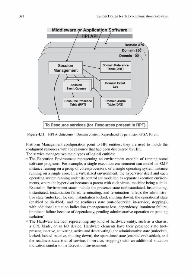
P1: OTA/XYZ P2: ABCc04 BLBK307-Bachmutsky September 2, 2010 13:18 Printer Name: Yet to Come
322 System Design for Telecommunication Gateways
Domain 375Domain 375
HPI API
Domain 250Domain 250
Domain 100Domain 100
SessionManagement
Middleware or Application Software
Domain ReferenceTable (DRT)
Domain ReferenceTable (DRT)
Resource PresenceTable (RPT)
Domain AlarmTable (DAT)
SessionEvent Queues
Domain Event Log
Resource PresenceTable (RPT)
Domain AlarmTable (DAT)
SessionEvent Queues
Domain Event Log
To Resource services (for Resources present in RPT)To Resource services (for Resources present in RPT)
Figure 4.11 HPI Architecture – Domain content. Reproduced by permision of SA Forum.
Platform Management configuration point to HPI entities; they are used to match theconfigured resources with the resource that had been discovered by HPI.The service manages two main types of logical entities:◦ The Execution Environment representing an environment capable of running some
software programs. For example, a single execution environment can model an SMPinstance running on a group of cores/processors, or a single operating system instancerunning on a single core. In a virtualized environment, the hypervisor itself and eachoperating system running under its control are modelled as separate execution environ-ments, where the hypervisor becomes a parent with each virtual machine being a child.Execution Environment states include the presence state (uninstantiated, instantiating,instantiated, instantiation failed, terminating, and termination failed), the administra-tive state (unlocked, locked, instantiation locked, shutting down), the operational state(enabled or disabled), and the readiness state (out-of-service, in-service, stopping),with additional situation indication (management loss, dependency, imminent failure,imminent failure because of dependency, pending administrative operation or pendingisolation).
◦ The Hardware Element representing any kind of hardware entity, such as a chassis,a CPU blade, or an I/O device. Hardware elements have their presence state (not-present, inactive, activating, active and deactivating), the administrative state (unlocked,locked, locked-inactive, shutting-down), the operational state (enabled or disabled), andthe readiness state (out-of-service, in-service, stopping) with an additional situationindication similar to the Execution Environment.

P1: OTA/XYZ P2: ABCc04 BLBK307-Bachmutsky September 2, 2010 13:18 Printer Name: Yet to Come
Software Technologies and Platforms 323
HPI API
Resource 720Resource 720
Middleware or Application Software
DomainSession control function
Resource 175Resource 175
Resource 80Resource 80
RPT identifies availableResources, and lists the Capabilities of each
RPT identifies availableResources, and lists the Capabilities of each
Power Control
Reset Control
Event Log
Configuration
Hot Swap
Power Control
Reset Control
Event Log
Configuration
Hot Swap
Inventory DataRepositories
Inventory DataRepositories
SensorsSensors Watchdog TimersWatchdog Timers
ControlsControls AnnunciatorsAnnunciators
Resource DataRecords (RDRs)
Figure 4.12 HPI Architecture – Resource content. Reproduced by permision of SA Forum.
Figure 4.13 shows the hierarchy of Platform Management in the system.One of the capabilities of the Platform Management Service is to enable applications
registering a callback function to receive service start/stop notifications from differententities. It also enables one to shut down the application own services smoothly, forexample owing to an administrative command.
– The Cluster Membership Service for a consistent view of the healthy and well-connectednodes in a cluster. In general, the different services and frameworks of the SA Forumspecifications are designed to be independent on each other and it is possible to implementone service only, or AIS only, or HPI only. The only significant exception for this rule isCluster Membership with most of other services using it as a base. The only two servicesthat do not depend on Cluster Membership are the Platform Management and the TimerService. On the other hand, it is logical to design a system where Cluster Membershipimplementation uses Platform Management to determine the presence and health of theconfigured nodes. The existing SA Forum specification assumes that there is only a singleinstance of the Cluster Membership Service in the system.
The specification does not enforce a particular criterion for membership determi-nation. For example, a democratic model can define that all existing nodes or somepre-configured portion of these nodes must agree to accept the new node into the
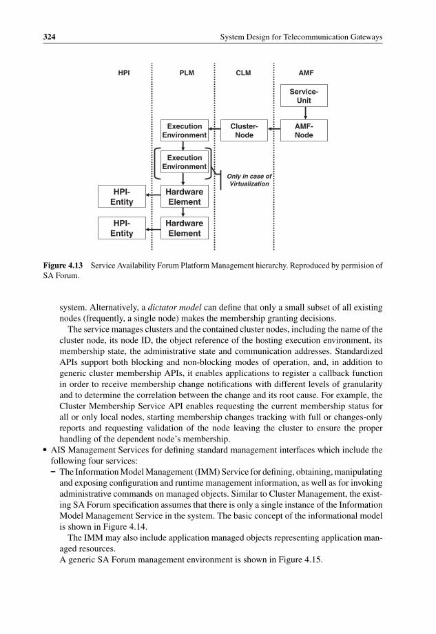
P1: OTA/XYZ P2: ABCc04 BLBK307-Bachmutsky September 2, 2010 13:18 Printer Name: Yet to Come
324 System Design for Telecommunication Gateways
HPI-Entity
HPI-Entity
Hardware Element
Hardware Element
Execution Environment
Execution Environment
Cluster-Node
AMF-Node
Service-Unit
AMFCLMPLMHPI
Only in case of Virtualization
Figure 4.13 Service Availability Forum Platform Management hierarchy. Reproduced by permision ofSA Forum.
system. Alternatively, a dictator model can define that only a small subset of all existingnodes (frequently, a single node) makes the membership granting decisions.
The service manages clusters and the contained cluster nodes, including the name of thecluster node, its node ID, the object reference of the hosting execution environment, itsmembership state, the administrative state and communication addresses. StandardizedAPIs support both blocking and non-blocking modes of operation, and, in addition togeneric cluster membership APIs, it enables applications to register a callback functionin order to receive membership change notifications with different levels of granularityand to determine the correlation between the change and its root cause. For example, theCluster Membership Service API enables requesting the current membership status forall or only local nodes, starting membership changes tracking with full or changes-onlyreports and requesting validation of the node leaving the cluster to ensure the properhandling of the dependent node’s membership.
� AIS Management Services for defining standard management interfaces which include thefollowing four services:– The Information Model Management (IMM) Service for defining, obtaining, manipulating
and exposing configuration and runtime management information, as well as for invokingadministrative commands on managed objects. Similar to Cluster Management, the exist-ing SA Forum specification assumes that there is only a single instance of the InformationModel Management Service in the system. The basic concept of the informational modelis shown in Figure 4.14.
The IMM may also include application managed objects representing application man-aged resources.A generic SA Forum management environment is shown in Figure 4.15.
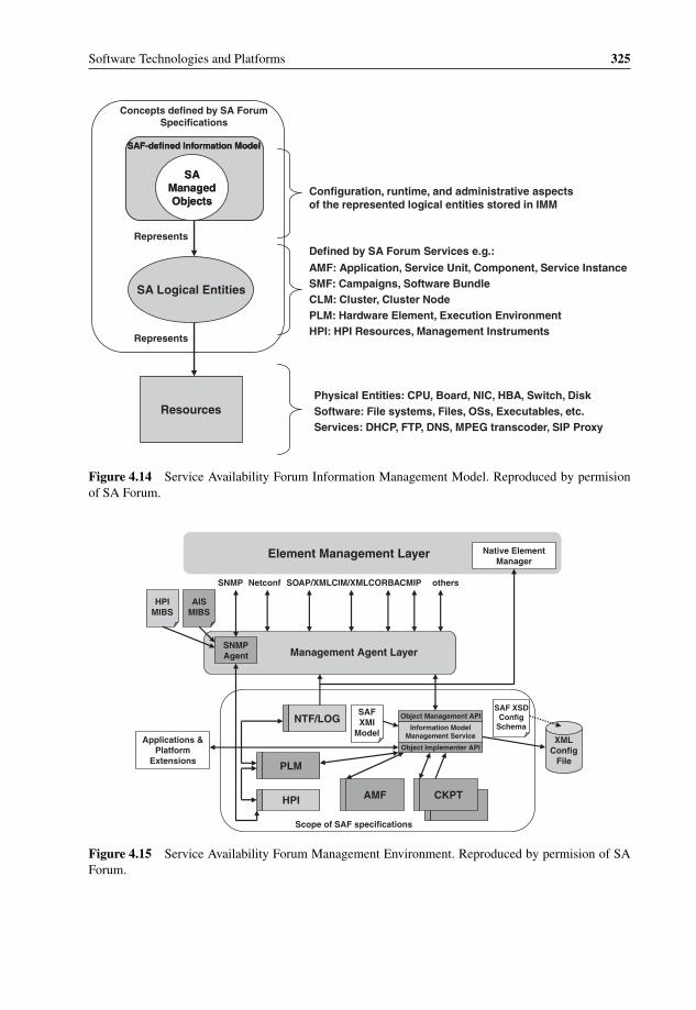
P1: OTA/XYZ P2: ABCc04 BLBK307-Bachmutsky September 2, 2010 13:18 Printer Name: Yet to Come
Software Technologies and Platforms 325
SAF-defined Information Model
SA Managed Objects
SAF-defined Information Model
SA Managed Objects
SA Logical Entities
Resources
Represents
Represents
Concepts defined by SA Forum Specifications
Configuration, runtime, and administrative aspects of the represented logical entities stored in IMM
Defined by SA Forum Services e.g.:
AMF: Application, Service Unit, Component, Service InstanceSMF: Campaigns, Software BundleCLM: Cluster, Cluster NodePLM: Hardware Element, Execution EnvironmentHPI: HPI Resources, Management Instruments
Physical Entities: CPU, Board, NIC, HBA, Switch, DiskSoftware: File systems, Files, OSs, Executables, etc.Services: DHCP, FTP, DNS, MPEG transcoder, SIP Proxy
Figure 4.14 Service Availability Forum Information Management Model. Reproduced by permisionof SA Forum.
Native Element Manager
Element Management Layer
SNMP Agent Management Agent Layer
othersSOAP/XMLCIM/XMLCORBACMIPNetconfSNMP
HPI MIBS
AIS MIBS
Applications & Platform
Extensions
HPI
PLM
NTF/LOGSAF XMI
Model
AMF CKPT
Information Model Management Service
Object Management API
Object Implementer API
SAF XSD Config
Schema
Scope of SAF specifications
XML Config
File
Figure 4.15 Service Availability Forum Management Environment. Reproduced by permision of SAForum.
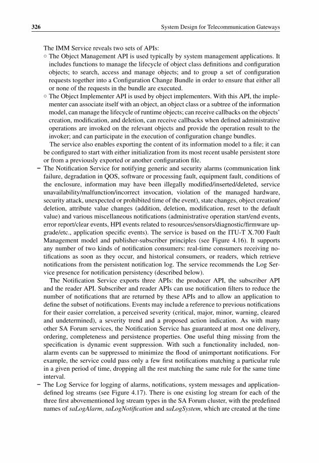
P1: OTA/XYZ P2: ABCc04 BLBK307-Bachmutsky September 2, 2010 13:18 Printer Name: Yet to Come
326 System Design for Telecommunication Gateways
The IMM Service reveals two sets of APIs:◦ The Object Management API is used typically by system management applications. It
includes functions to manage the lifecycle of object class definitions and configurationobjects; to search, access and manage objects; and to group a set of configurationrequests together into a Configuration Change Bundle in order to ensure that either allor none of the requests in the bundle are executed.
◦ The Object Implementer API is used by object implementers. With this API, the imple-menter can associate itself with an object, an object class or a subtree of the informationmodel, can manage the lifecycle of runtime objects; can receive callbacks on the objects’creation, modification, and deletion, can receive callbacks when defined administrativeoperations are invoked on the relevant objects and provide the operation result to theinvoker; and can participate in the execution of configuration change bundles.The service also enables exporting the content of its information model to a file; it can
be configured to start with either initialization from its most recent usable persistent storeor from a previously exported or another configuration file.
– The Notification Service for notifying generic and security alarms (communication linkfailure, degradation in QOS, software or processing fault, equipment fault, conditions ofthe enclosure, information may have been illegally modified/inserted/deleted, serviceunavailability/malfunction/incorrect invocation, violation of the managed hardware,security attack, unexpected or prohibited time of the event), state changes, object creation/deletion, attribute value changes (addition, deletion, modification, reset to the defaultvalue) and various miscellaneous notifications (administrative operation start/end events,error report/clear events, HPI events related to resources/sensors/diagnostic/firmware up-grade/etc., application specific events). The service is based on the ITU-T X.700 FaultManagement model and publisher-subscriber principles (see Figure 4.16). It supportsany number of two kinds of notification consumers: real-time consumers receiving no-tifications as soon as they occur, and historical consumers, or readers, which retrievenotifications from the persistent notification log. The service recommends the Log Ser-vice presence for notification persistency (described below).
The Notification Service exports three APIs: the producer API, the subscriber APIand the reader API. Subscriber and reader APIs can use notification filters to reduce thenumber of notifications that are returned by these APIs and to allow an application todefine the subset of notifications. Events may include a reference to previous notificationsfor their easier correlation, a perceived severity (critical, major, minor, warning, clearedand undetermined), a severity trend and a proposed action indication. As with manyother SA Forum services, the Notification Service has guaranteed at most one delivery,ordering, completeness and persistence properties. One useful thing missing from thespecification is dynamic event suppression. With such a functionality included, non-alarm events can be suppressed to minimize the flood of unimportant notifications. Forexample, the service could pass only a few first notifications matching a particular rulein a given period of time, dropping all the rest matching the same rule for the same timeinterval.
– The Log Service for logging of alarms, notifications, system messages and application-defined log streams (see Figure 4.17). There is one existing log stream for each of thethree first abovementioned log stream types in the SA Forum cluster, with the predefinednames of saLogAlarm, saLogNotification and saLogSystem, which are created at the time

P1: OTA/XYZ P2: ABCc04 BLBK307-Bachmutsky September 2, 2010 13:18 Printer Name: Yet to Come
Software Technologies and Platforms 327
SNMPManager
CIM/WEBMClient
Notification Log File
Log Service
Transport Service (e.g., Message Service or Event Service)
NotificationService
Forwarding
LoggingNotificationServer
SNMP MIB CIM MOF
SNMP TrapsCIM Indications
ApplicationProducer
NotificationLibrary
ApplicationSubscriberNotification
Library
SNMP AgentSubscriber/Reader
NotificationLibrary
CIM ProviderSubscriber/Reader
NotificationLibrary
Alarm MgrReader
NotificationLibrary
Figure 4.16 Service Availability Forum Notification Service. Reproduced by permision of SA Forum.
Node WNode VNode U
LogViewer
LogService
NotificationService
AlarmLog File
Configuration File
NotificationLog File
Configuration File
SystemLog File
Configuration File
AlarmLog File
NotificationLog File
SystemLog File
Log Servicelibrary
ApplicationLog File
Configuration File
ApplicationLog File
ApplicationProcess2
ApplicationProcess1
Log Servicelibrary
Log Servicelibrary
ApplicationProcess2
ApplicationProcess1
Log Servicelibrary
Log Servicelibrary
IMMObject
ImplementerAPI
Figure 4.17 Service Availability Forum Log Service entities. Reproduced by permision of SA Forum.

P1: OTA/XYZ P2: ABCc04 BLBK307-Bachmutsky September 2, 2010 13:18 Printer Name: Yet to Come
328 System Design for Telecommunication Gateways
of the Log Service initialization; however, there can be any number of application logstreams and any application may open multiple application log streams. The service istargeted primarily at network or system administrators, or automated tools for analysingthe logged information in order to troubleshoot misconfigurations, network disconnectsand unavailable resources. It is also used sometimes to record important service events,such as end-user network entry and exit, session start and end and so on. These recordscan be used later for dispute resolutions or other purposes.
Before the logging action is performed, application and system log streams can gothrough the log filtering functionality configured by the system administrator and basedmostly on the log record severity value; however, other criteria can be applied. Onepractical example could be the case when the only persistent storage available is the flashdisk, or even that is not available and only a RAM disk can be used and there is nonetworking connectivity for any reason. During such a failure period, the policy mightfilter any logs except the severe ones because of the limited storage capacity or significantrestriction of the number of write cycles for the storage medium. The logger entity canimplement a callback function to be notified about the currently applied filter so as tominimize unnecessary logging calls when the records would be dropped anyway.
Log records are encoded using the US-ASCII character set and formatted using formattokens into format expressions. These format expressions can be configured using LogService APIs and well-known default formats are applied when the configuration is eithernon-existent or invalid. The formal representation of a format token is the following:
<@><C|S|N><letter><field-size>
where◦ <@> All token sequences start with the ‘at’ symbol.◦ <C|S|N> The next character indicates the record type: C means a common log record
field, S means a system or application log record field, N means a notification or alarmfield.
◦ <letter> A distinct character that maps to a specific field or subfield of a log record.◦ <field-size> Some token types optionally allow its output field size to be specified.Format tokens are sequenced into the format expressions. For example, the default logrecord format expression for the application and system log streams is the following:
@Cr @Ch:@Cn:@Cs @Cm/@Cd/@CY @Sv @Sl ‘@Cb’
where◦ @Cr is an internally generated 10-digit log record Identifier.◦ @Ch is a 2-digit hour of the day.◦ @Cn is a 2-digit minute of the hour.◦ @Cs is a 2-digit second of the minute.

P1: OTA/XYZ P2: ABCc04 BLBK307-Bachmutsky September 2, 2010 13:18 Printer Name: Yet to Come
Software Technologies and Platforms 329
◦ @Cm is a 2-digit month.◦ @Cd is a 2-digit day.◦ @CY is a 4-digit year.◦ @Sv is a 2-character severity identifier, which can be one of the following: EM for
EMERGENCY, AL for ALARM, CR for CRITICAL, ER for ERROR, WA for WARN-ING, NO for NOTIFICATION, IN for INFO.
◦ @Sl is a logger name.◦ @Cb is a printable string.The Log Service has to take into account a number of log file properties, such as the logfile format as described above, a file network path (standard relative POSIX subdirectorypathname), a file name (used to create two files: <filename>.cfg, which contains the for-mat expression and key configuration information associated with the log output files, and<filename> <createtime>. log with the logging information starting at <createtime>time), a maximum file size (can be configured as unlimited; otherwise, the size has tobe enforced by the Log Service, and the enforcement action is defined by another fileproperty, full action, which can be either ‘wrap’ requiring to delete the oldest log recordsto free space for new ones, or ‘halt’ causing the logging to be stopped to the file reachedthe maximum size, or ‘rotation’ with an old file being closed and a new file opened forfuture log records; in the latter case, the maximum number of files can be specified withthe oldest file being deleted before creating the new one when that number is reached), afixed log record size (enforced by the Log Service through the record truncation), a highavailability flag implying the file replication and persistency (alarm and notification logfiles are always highly available).
– The Security Service provides access security functions to the AIS Services and HPI toprotect the infrastructure from misuse, to avoid the unauthorized access to SA Forumapplications and their managed data and to preserve their integrity; SA Forum servicesthemselves are assumed to be trusted and do not require authorization. The securitycontext is a set of permissions from the client process to access different AIS Services.The Security Service specification allows a process to have different security contexts forthe different AIS Services.
Each security-enabled service must request an authorization from the Security Servicefor any other service access. As of the time of writing, the Security Service supportedonly the UID authentication mechanism, but other mechanisms, such as Private KeyInfrastructure (PKI) and shared secrets, are planned to be supported in the future. It isimportant to understand that the SA Forum Security Service is not designed to providemechanisms such as an encryption for the data that passes through different services.Besides, the Security Service has to be agnostic to the underlying crypto algorithmsand libraries. To accommodate the capability of dynamic policy changes, the servicesubscribers register a callback function used to notify about the change.
To simplify the failover or switchover scenario in highly available systems, it isrecommended that both protected and protecting peers have the same security contextconfiguration. The best implementation would be for the Availability Management Frame-work to either verify or enforce the same configuration in this case.
It is assumed that the OS security mechanisms guarantee that only the AIS Services usethe Security Service as shown in Figure 4.18.
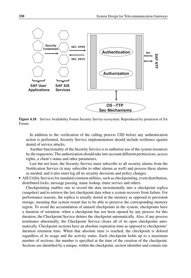
P1: OTA/XYZ P2: ABCc04 BLBK307-Bachmutsky September 2, 2010 13:18 Printer Name: Yet to Come
330 System Design for Telecommunication Gateways
Authentication
Authorization
OS –TTP Sec Mechanisms
SA
F N
TF
SecAlarms
SEC_OPER
SEC_DECS
Security Credentials
SAF User Applications
SAF AIS Services
Figure 4.18 Service Availability Forum Security Service ecosystem. Reproduced by permision of SAForum.
In addition to the verification of the calling process UID before any authenticationaction is performed, Security Service implementation should include resilience againstdenial of service attacks.
Another functionality of the Security Service is to authorize use of the system resourcesby the requestors. The authorization should take into account different permissions, accessrights, a client’s status and other parameters.
Last but not least, the Security Service must subscribe to all security alarms from theNotification Service (it may subscribe to other alarms as well) and process these alarmsas needed, and it also must log all its security decisions and policy changes.
� AIS Utility Services for standard common utilities, such as checkpointing, event distribution,distributed locks, message passing, name lookup, timer service and others.
Checkpointing enables one to record the data incrementally into a checkpoint replica(snapshot) and to retrieve the last checkpoint data when a system recovers from failure. Forperformance reasons, the replica is usually stored in the memory as opposed to persistentstorage, meaning that system restart has to be able to preserve the corresponding memoryregion. To avoid the accumulation of unused checkpoints in the system, checkpoints havea duration of retention: when a checkpoint has not been opened by any process for thisduration, the Checkpoint Service deletes the checkpoint automatically. Also, if any processterminates abnormally, the Checkpoint Service closes all of its open checkpoints auto-matically. Checkpoint sections have an absolute expiration time as opposed to checkpoints’duration retention time. When that absolute time is reached, the checkpoint is deletedregardless of its usage and the activity status. Each checkpoint holds up to a maximumnumber of sections; the number is specified at the time of the creation of the checkpoint.Sections are identified by a unique, within the checkpoint, section identifier and contain raw

P1: OTA/XYZ P2: ABCc04 BLBK307-Bachmutsky September 2, 2010 13:18 Printer Name: Yet to Come
Software Technologies and Platforms 331
data not interpreted in any way by the Checkpoint Service. Sections can be created or deleteddynamically and they can have different sizes even in the same checkpoint. It is importantto note that the Checkpoint Service by itself does not provide any synchronization orevent ordering and multiple processes writing simultaneously to the same checkpoint mightneed to implement their own synchronization using Lock Service or other methods. TheCheckpoint Service can support synchronous or asynchronous modes for the correct balancebetween performance and data protection and the mode is defined when the checkpoint iscreated. In the synchronous mode, section creation/deletion and data modification callsreturn only when all checkpoint replicas have been updated; in addition, the CheckpointService guarantees that a replica is not partially updated: a replica is either updated with alldata specified in the write call or is not updated at all. In the asynchronous mode, sectioncreation/deletion and data modification calls return immediately after updating of a specialactive replica without waiting for update of other replicas. The asynchronous service cannotguarantee that all checkpoint replicas are identical, but there is a capability to invoke anexplicit synchronization process of all the replicas. In addition, the asynchronous modesupports the atomic data update, where the service ensures that either none of or the entiredata has been updated and non-atomic update; in the latter case the Checkpoint Servicemarks partially updated sections as corrupted if the checkpoint cannot be finished owing toprocess failure.
The Event Service is a publish/subscribe multipoint-to-multipoint communication mech-anism that is based on the concept of the cluster-wide named event channels: any number ofpublishers communicates asynchronously with any number of subscribers by using eventsover an event channel. Publishers can also be subscribers on the same event channel. Sub-scribers are anonymous, which means that they may join and leave an event channel at anytime without involving the publisher(s). The SA Forum Event Service has the followingproperties:– Best effort delivery: an event may be lost or delivered to only a subset of the subscribers.
When the Event Service detects that a subscriber did not receive the event for any reason(overflow, communication failure, overload conditions, etc.), it publishes a high priorityLost Event on the event channel. The service will continue to publish the Lost Event whenthe loss conditions is detected again and again; however, it makes sure that there is only asingle such event published at any point of time, meaning that the new Lost Event is notpublished until the previous one is consumed.
– At most one delivery without event duplication.– Event priority: high priority events are delivered ahead of lower priority ones.– Event ordering: events of the same priority are delivered to the same subscriber in the
order of their publishing.– Event completeness: every event is either delivered fully with all of its data content or not
delivered at all.– Retention time: events may include the duration time; these events are removed automat-
ically from the event channel when the time interval expires.– Publish time: the absolute time when the event has been published.– Publisher name: the publisher’s identification information.– Event ID: the event internal identification assigned by the Event Service; there should be
no assumptions on how the ID is set, and the only requirement is that the ID has to beunique within the same event channel.

P1: OTA/XYZ P2: ABCc04 BLBK307-Bachmutsky September 2, 2010 13:18 Printer Name: Yet to Come
332 System Design for Telecommunication Gateways
– Persistence: the service may optionally provide a capability of the events to survive thenode failure (or an administrative cluster shutdown) and automatically publish these eventsafter the recovery.The event subscribers can specify a filter for the event delivery. For example, the publisher
may publish an event when a new end-user requires the service, such as enters the network,opens an active session, etc. It will also publish the end-user profile data as a part of the event.One of subscribers may request to receive such an event, but only when the new end-user hasbeen classified as ‘gold’. Different subscribers could have different filters. The filters use thedefinition of patterns and pattern arrays provided by the publisher, which requires patternformat sharing between publisher and subscribers. There are four filter types supported forevery pattern:– The prefix filter to match the specified amount of data at the beginning of the pattern.– The suffix filter to match the specified amount of data at the end of the pattern.– The exact filter to match exactly the entire pattern.– The pass-all filter to match any pattern.
The Lock Service implements distributed globally-named lock resources and enablesprocesses in different nodes to compete with each other for access to a shared resource.The Lock Service provides a simple lock model supporting one locking mode for exclusiveaccess, where only one exclusive lock can be granted against a lock resource at any timeand another one for shared access, also called protected read, with any number of sharedlocks being able to be granted against a lock resource. The service has to include mandatoryfeatures, such as synchronous and asynchronous calls, lock timeout, trylock, and lock waitnotifications; it may optionally implement deadlock detection, including application noti-fication about the deadlock and lock orphaning functionalities. The Lock Service supportsan API to query for support of one or more of the optional features. To prevent deadlock,applications might define a numerical order 0, 1,. . ., n for the locks that they use and theclaimed lock number must be greater than the number of another lock being held. In somescenarios, such as process termination or cluster membership termination, the service canstrip the lock from its holder.
The Message Service provides cluster-wide interprocess communication using persistent(i.e. always exists until deleted explicitly) or non-persistent (deleted after the configurableretention time since the last access) message queues, optionally with separate priority areashousing different message priorities, a model where a particular message queue can havemultiple senders but at most one receiver at any given time, which enables point-to-point ormulti-point-to-point communication. To simplify the redundancy architecture and failoverprocedures, senders are totally unaware of the fact that the originally intended receiver hasbeen replaced by its protecting peer after the failure and the switchover procedure. TheMessage Service supports a powerful feature of message queues grouping. Queue groupshave a number of important properties:– They permit multipoint-to-multipoint communication. In a unicast message queue group,
each message is sent to only one of the message queues in the group. In a multicastmessage queue group, a message can be sent to more than one message queue in thegroup. There are multiple policies defined by the Message Service specification:◦ Equal Load Distribution (unicast).
Destination entities are served one-by-one in a round-robin fashion. If any mes-sage cannot be delivered to its destination for any reason, the Message Service

P1: OTA/XYZ P2: ABCc04 BLBK307-Bachmutsky September 2, 2010 13:18 Printer Name: Yet to Come
Software Technologies and Platforms 333
implementation may either immediately terminate the message processing, or alter-natively it may select the next destination and continue the procedure. This policy ismandatory.
◦ Local Equal Load Distribution (unicast).The policy is very similar to the equal load distribution, but is applied only to thedestination entities located in the same node as a message originator, referred to hereand later as local, with the entity located on a different node being referred to as remote.
◦ Local Best Queue (unicast).The local message queue with the largest amount of available space is selected; multiplequeues of the same largest size are processed one-by-one in a round-robin fashion. Ifno local message queue exists, a remote queue or a queue that is not opened by anyprocess is selected according to the equal load distribution policy. Errors are also handledsimilarly to the equal load distribution definition.
◦ Broadcast (multicast).The message is sent to all destination entities of the message queue group that have asufficient space to receive the message.
They are identified by logical names, so that a sender or a receiver process is unawareof the number of message queues and of the physical location of message queues withwhich it is communicating.They can be used to maintain transparency of the sender process to faults in the receiverprocesses, because there is no change from the sender point of view, it continues tocommunicate with the same message queue group being served by other receiver(s).
Messages consist of the data, the sequence of bytes opaque to the Message Service andthe metadata subdivided into the standard and fixed-size implementation-specific parts.The standard metadata portion of a message covers its type, version, priority, data size,variable-length sender name and sender name length.
Similar to the described above Event Service properties, the message delivery has anumber of properties:– Priority.
Higher priority messages are received before lower priority. Messages with the samepriority and the same sender are received in the order of their sending. Messages fromdifferent priorities may be processed out-of-order.
– Message integrity and at-most-once delivery.The Message Service guarantees that messages are neither altered nor duplicated(meaning that every message is delivered only once to every destination entity for bothunicast and multicast types); and they are always complete.
– Delivery guarantees.A unicast message should not be accepted by the Message Service if the destinationentity does not have the space required to receive the message. This requirement is themajor driver for the capability to return a Queue Full error indication to the sender. Formulticast messages the situation is different and the specification defines that the messagesend operation is finished successfully if the message can be delivered to at least onedestination entity.
– Acknowledgement.There are different acknowledge levels that can be requested by a message sender: anotification of the completeness of the sending process and its result, a notification that
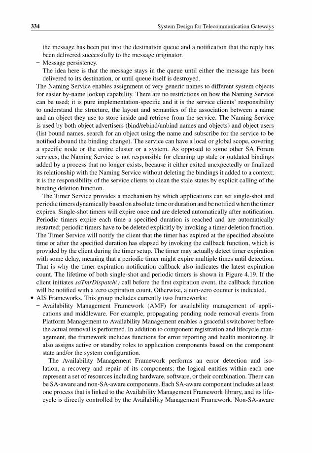
P1: OTA/XYZ P2: ABCc04 BLBK307-Bachmutsky September 2, 2010 13:18 Printer Name: Yet to Come
334 System Design for Telecommunication Gateways
the message has been put into the destination queue and a notification that the reply hasbeen delivered successfully to the message originator.
– Message persistency.The idea here is that the message stays in the queue until either the message has beendelivered to its destination, or until queue itself is destroyed.
The Naming Service enables assignment of very generic names to different system objectsfor easier by-name lookup capability. There are no restrictions on how the Naming Servicecan be used; it is pure implementation-specific and it is the service clients’ responsibilityto understand the structure, the layout and semantics of the association between a nameand an object they use to store inside and retrieve from the service. The Naming Serviceis used by both object advertisers (bind/rebind/unbind names and objects) and object users(list bound names, search for an object using the name and subscribe for the service to benotified abound the binding change). The service can have a local or global scope, coveringa specific node or the entire cluster or a system. As opposed to some other SA Forumservices, the Naming Service is not responsible for cleaning up stale or outdated bindingsadded by a process that no longer exists, because it either exited unexpectedly or finalizedits relationship with the Naming Service without deleting the bindings it added to a context;it is the responsibility of the service clients to clean the stale states by explicit calling of thebinding deletion function.
The Timer Service provides a mechanism by which applications can set single-shot andperiodic timers dynamically based on absolute time or duration and be notified when the timerexpires. Single-shot timers will expire once and are deleted automatically after notification.Periodic timers expire each time a specified duration is reached and are automaticallyrestarted; periodic timers have to be deleted explicitly by invoking a timer deletion function.The Timer Service will notify the client that the timer has expired at the specified absolutetime or after the specified duration has elapsed by invoking the callback function, which isprovided by the client during the timer setup. The timer may actually detect timer expirationwith some delay, meaning that a periodic timer might expire multiple times until detection.That is why the timer expiration notification callback also indicates the latest expirationcount. The lifetime of both single-shot and periodic timers is shown in Figure 4.19. If theclient initiates saTmrDispatch() call before the first expiration event, the callback functionwill be notified with a zero expiration count. Otherwise, a non-zero counter is indicated.
� AIS Frameworks. This group includes currently two frameworks:– Availability Management Framework (AMF) for availability management of appli-
cations and middleware. For example, propagating pending node removal events fromPlatform Management to Availability Management enables a graceful switchover beforethe actual removal is performed. In addition to component registration and lifecycle man-agement, the framework includes functions for error reporting and health monitoring. Italso assigns active or standby roles to application components based on the componentstate and/or the system configuration.
The Availability Management Framework performs an error detection and iso-lation, a recovery and repair of its components; the logical entities within each onerepresent a set of resources including hardware, software, or their combination. There canbe SA-aware and non-SA-aware components. Each SA-aware component includes at leastone process that is linked to the Availability Management Framework library, and its life-cycle is directly controlled by the Availability Management Framework. Non-SA-aware
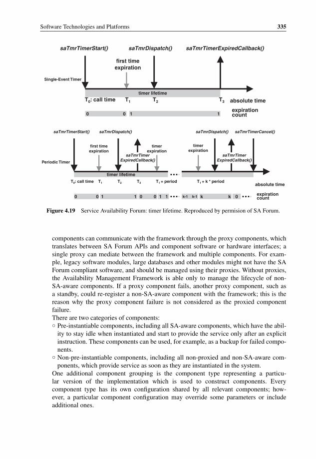
P1: OTA/XYZ P2: ABCc04 BLBK307-Bachmutsky September 2, 2010 13:18 Printer Name: Yet to Come
Software Technologies and Platforms 335
saTmrTimerExpiredCallback()saTmrDispatch()saTmrTimerStart()
Single-Event Timer
first time expiration
timer lifetimeT0 T: call time 1 T2 T3 absolute time
expiration count0 0 11
saTmrTimerStart()
first time expiration
saTmrDispatch()
timer expiration
Periodic Timer
saTmrTimerExpiredCallback()
saTmrTimerExpiredCallback()
saTmrTimerCancel()saTmrDispatch()
timer expiration
timer lifetimeT0 T: call time 1 T2 T3 T1 T+ period 1 + k * period
absolute time
expirationcount0 0 1 1 0 0 1 1 k-1 k-1 k k 0
Figure 4.19 Service Availability Forum: timer lifetime. Reproduced by permision of SA Forum.
components can communicate with the framework through the proxy components, whichtranslates between SA Forum APIs and component software or hardware interfaces; asingle proxy can mediate between the framework and multiple components. For exam-ple, legacy software modules, large databases and other modules might not have the SAForum compliant software, and should be managed using their proxies. Without proxies,the Availability Management Framework is able only to manage the lifecycle of non-SA-aware components. If a proxy component fails, another proxy component, such asa standby, could re-register a non-SA-aware component with the framework; this is thereason why the proxy component failure is not considered as the proxied componentfailure.There are two categories of components:◦ Pre-instantiable components, including all SA-aware components, which have the abil-
ity to stay idle when instantiated and start to provide the service only after an explicitinstruction. These components can be used, for example, as a backup for failed compo-nents.
◦ Non-pre-instantiable components, including all non-proxied and non-SA-aware com-ponents, which provide service as soon as they are instantiated in the system.
One additional component grouping is the component type representing a particu-lar version of the implementation which is used to construct components. Everycomponent type has its own configuration shared by all relevant components; how-ever, a particular component configuration may override some parameters or includeadditional ones.

P1: OTA/XYZ P2: ABCc04 BLBK307-Bachmutsky September 2, 2010 13:18 Printer Name: Yet to Come
336 System Design for Telecommunication Gateways
Node XNode WNode VNode U
Service Instance DService Instance B
ServiceGroupSG2 Service Unit S5Service Unit S4Service Unit S3
Service Instance A
ServiceGroupSG1Service Unit S1 Service Unit S2
Active Active Active
StandbyStandby
Standby
ProtGroupA1
ProtGroup
A2
ComponentC1
ComponentC2
ComponentC3
ComponentC4
ProtGroupB1 Prot
GroupD1
ComponentC5 Component
C6
ComponentC7
ComponentService Instance A1ComponentService Instance A2
ComponentService Instance B1
ComponentService Instance D1
Figure 4.20 Availability Management Framework system view example. Reproduced by permision ofSA Forum.
For management simplification purposes, a set of components can be aggregatedinto the service unit and further into service groups and even further into applica-tions; and most management instructions deal often with service units or a higherlevel of aggregation as opposed to individual components. For example, every instanceof redundancy can be defined at the service unit level enabling a significant reduction ofmanagement objects and corresponding states in the system to be tracked and controlled.One of the restrictions for a service unit is that it may contain only components with thesame scope of locality belonging to the same node.
The component service instance (CSI) in Figure 4.20 represents the workload of aspecific component, and CSIs can be aggregated into service instances.
The Availability Management Framework maintains many different states, including:◦ A presence at the service unit and component levels, which can be one of the
following: uninstantiated, instantiating, instantiated, terminating, restarting,instantiation-failed and termination-failed.
◦ Service unit administrative state: locked (prohibited to provide service), locked-instantiation, unlocked and shutting-down.
◦ Service unit and component operational state: enabled or disabled.◦ Service unit readiness state: out-of-service, in-service, stopping. When a service unit is
in the stopping state, no service instance can be assigned to it, but service instances thatare already assigned are not removed until the explicit indication. It enables gracefulservice unit removal during an upgrade, overload or other conditions.

P1: OTA/XYZ P2: ABCc04 BLBK307-Bachmutsky September 2, 2010 13:18 Printer Name: Yet to Come
Software Technologies and Platforms 337
OtherAIS
Services
OtherAIS
Services
SoftwareManagementFramework
HardwarePlatformInterface
AvailabilityManagementFramework
AdminAdmin
AMFEntityAMF
Entity
HPI APIHPI API
AIS Service APIAIS Service API
AMF APIAMF API
SMF APISMF API
OM API
OI API
InformationManagement
ModelService
Figure 4.21 Service Availability Forum: Software Management Framework. Reproduced by permisionof SA Forum.
◦ High availability state: active, standby, quiescing and quiesced. In the quiescing state,the service unit is going to give up its active state and thus cannot accept any new usersfor the service, while serving existing users until they are finished. When no user is leftfor that service, the state is changed to quiesced.
◦ High availability readiness state: ready-for-assignment, ready-for-active-degraded, not-ready-for-active, not-ready-for-assignment.
◦ Service instance assignment state: unassigned, fully-assigned, partially-assigned.– Software Management Framework (see Figure 4.21) for managing middleware and appli-
cation software during hardware, operating system, middleware and application upgradesand downgrades while taking service availability into account. All various logical enti-ties that are used to represent and control software execution are designated as softwareentities. A collection of interdependent software modules for these software entities isdelivered to the system in the form of a software bundle, the smallest unit recognized bythe Software Management Framework. The collection of software bundles available inthe system is called the software catalogue. The Software Management Framework main-tains the information about the availability, the contents and the deployment of differentsoftware bundles, which become available in the software repository, a storage location as-sociated with the system. From the software repository, a software bundle can be installedin one or more locations within the system. Software packaging in software bundles andsoftware bundles delivery to the software repository is implementation-specific.
Software bundles delivered to the software repository must be verified, which isimplementation-specific. This verification should include:◦ A check of the integrity and the origin of all software packages that make up the bundle.
A check that all other packages, indicated in the package dependency list, are availablein the repository or have been delivered at the same time.◦ A check that the bundle has been added properly to the repository and can be used as
an installation source.

P1: OTA/XYZ P2: ABCc04 BLBK307-Bachmutsky September 2, 2010 13:18 Printer Name: Yet to Come
338 System Design for Telecommunication Gateways
The framework performs system migration based on the specification provided in theform of an XML file, while maintaining the state model, monitoring for potential errorsituations and deploying error recovery procedures as required. The available API enablesregistering the callbacks when a relevant upgrade is initiated and/or progresses throughsignificant milestones.
Software installation can be online and offline, or out-of-service. The installation cantake advantage of the high availability functionality of the system. For example, the newsoftware can be installed in the standby sub-system, verified and trigger a switchoverfrom active components to newly installed standby components. After the switchover, aprevious active is restarted and upgraded when it reboots; after the upgrade, it can becomea standby again. A similar functionality can be achieved in a single-step upgrade by usingsoftware virtualization mechanisms; the difference from the above scheme is that the newsoftware is installed into a new virtual machine and processing after successful installationand corresponding data synchronization is switched to this virtual machine.
The Software Management Framework relies on the Notification Service being notifiedabout errors that may be the result of an upgrade process. It also subscribes to state changenotifications issued by the Availability Management Framework for a correlation with theupgrade procedure. The Software Management Framework also publishes state changenotifications during an upgrade process.
The entire software upgrade diagram is shown in Figure 4.22.
Notify users, stop history,
remove duplicates
Notify users, stop history,
remove duplicates
Restore backed up
state
Restore original configuration by
reverting procedures step by step
Notify registered users that an upgrade is about to start
to obtain their consent, check prerequisites
Call back registered users to backup their data/state,
start logs, create a cluster-wide backup
An upgrade step is composed of a series of actions
Partial checks can be interleaved
with actions within the step
Verify the upgrade procedure if its
entire scope is in the expected state
Check cluster-wide consistency, if its safe to leave the system in this state; requires application-level verifications over some time and wait for admin confirmation
Execute Step
Verify StepVerify Step
Create BackupCreate Backup
upgrade permitted
successsuccess
successsuccess
failurefailure
Undo Step
retry
Undo Step
retry
Verify Procedure
no more steps
Verify Procedure
no more stepsmore stepsmore steps
more proceduresmore procedures
failurefailure
rollbackrollback
Verify Campaign
no more procedures
Verify Campaign
no more procedures
success
failurefailure
failurefailure
Fallbackfallbackfallback
rollbackrollback
RollbackRollbackfallbackfallback
cannot upgradeTerminate Campaign
cannot upgradeTerminate Campaign
Commit RollbackCommit Rollback
successsuccess
Initiate CampaignInitiate Campaign
Remove history, backups, etc.
notify users and stop logs
success Commit Campaignsuccess Commit Campaign
cannot upgradecannot upgrade
Figure 4.22 Service Availability Forum: software upgrade diagram. Reproduced by permision of SAForum.

P1: OTA/XYZ P2: ABCc04 BLBK307-Bachmutsky September 2, 2010 13:18 Printer Name: Yet to Come
Software Technologies and Platforms 339
It is important that every upgrade step is verified before going to the next step. If theverification fails, the failed step has to be reversed to its previous state and the upgradecan be retried. If retry is not possible, or the verification fails, complete rollback to theinitial state has to be performed. If either such complete rollback is not possible at all,or not possible in the pre-defined upgrade time window, or a failure is detected duringthe rollback process, a fallback should be triggered to restore the state saved duringthe backup operation. Usually, any fault triggers administrator notification and it is theadministrator’s responsibility to authorize the recovery steps. The same is true regardingthe entire upgrade commitment, which is usually performed by the administrator.
In many software upgrade procedures, some runtime and persistent state changes occurbetween the upgrade and the failure event. For example, new subscribers could be addedor new routing table entries have been learned. If the software restarts, all such changescould be lost. It is possible to record all changes from the last saved status and play themback after the restart. Such playback of the saved records is called rollforward. However,rollforward triggering and implementation are not mandatory components in the SoftwareManagement Framework.
The framework defines two upgrade types, rolling and single-step. In the rolling upgradethe whole procedure is divided into multiple deactivation-activation steps for separateunits:◦ Lock the deactivation unit.◦ Terminate the deactivation unit.◦ Offline uninstallation of old software.◦ Modify the information model and set the maintenance status.◦ Offline installation of new software.◦ Instantiate the activation unit.◦ Unlock the activation unit.
In the single-step upgrade, the sequence above is performed once with every stepapplying corresponding actions to all units before moving to the next step. Without theabovementioned redundancy or virtualization, the single-step upgrade or rolling cannotbe performed while being in full service. On the other hand, the biggest advantage of thescheme is its simplicity and easier development, because there is no requirement that thenew version of unit A will be fully compatible with an old version.
In some designs the service affecting upgrade can be implemented as service degra-dation as opposed to service outage. This would be true, for example, in a multiinstanceimplementation, where an upgrade can be performed instance-by-instance, causing onlya temporary scalability and/or performance reduction.
As mentioned above, SA Forum specifications were designed to be independent. However,a specific implementation may create such dependencies, even mutual ones. For example,checkpointing is modelled as an application under the Availability Management Frameworkumbrella, and on the other hand the AMF can use checkpointing for state replications.
As of the time of writing, the latest SA Forum Specification, Release 6 of October 2008,added Platform Management with managed objects, representing operating systems and vir-tualization layers. The complete information model represents hardware, virtualization andoperating system layers, as well as middleware and applications, enabling fault correlationto be performed across all platform layers. The Release 6 AIS specification extends the

P1: OTA/XYZ P2: ABCc04 BLBK307-Bachmutsky September 2, 2010 13:18 Printer Name: Yet to Come
340 System Design for Telecommunication Gateways
Component Component C1
Component Component D1
Service Unit S1
Service Unit S2
Service Group
NodeX1
Node X2
Protection Group
Protection Group
. . . .
Component Service Instance
A1
Component Service Instance
A2
Component Service Instance
B1
Component Service Instance
B2
Service Instance
A
Service Instance
B
Service Instance
E
Active
Active
Active
ActiveStandby
Standby Standby
Standby
Component C2
Component D2
Figure 4.23 Service Availability Forum AIS model. Reproduced by permision of SA Forum.
Information Model Management (IMM) service to enable processes to register to validateconfiguration changes or to listen to changes without being an object’s run-time owner, whichallows processes to perform a global validation or multiple processes to be able to react tochanges.
Manfred Reitenspiess and Louise E. Moser published in June 2004 a good tutorial forbasic SA Forum principles in a CommDesign article.28 Based on the tutorial, an applicationis structured into one or more service units and a service unit is structured into one or morecomponents, as shown in Figure 4.23.
The article states that typically, although not required by the AIS specification, a componentcorresponds to a single physical process and a service unit is a set of components that areco-located on the same node and are all placed in-service, or taken out-of-service, together.The application can be structured into implementation-specific service instances supported byservice units (a service unit might support many service instances) and every service instanceis structured into component service instances associated with components in that serviceunit. Redundant service units are grouped together into a service group that supports a givenredundancy model.
28 http://www.commsdesign.com/design_corner/showArticle.jhtml?articleID=21700010.

P1: OTA/XYZ P2: ABCc04 BLBK307-Bachmutsky September 2, 2010 13:18 Printer Name: Yet to Come
Software Technologies and Platforms 341
Node 1 Node 2 Node 3
Service Group
Service Unit 1 Service Unit 2 Service Unit 3
Component 1
Component 2
Component 3
Component 4
Component 5
Component 6
AAA
AA
Component Service Instance 1
Service Instance 1
Component Service Instance 2
Service Instance 2
Figure 4.24 Service Availability Forum N-way active redundancy model. Reproduced by permisionof SA Forum.
Each component service instance is associated with a protection group consisting of mul-tiple components providing either active processing for the component service instance, or astandby capability to be ready to continue the processing in the event of an active componentfailure.
The AMF defines the following mandatory models:
� No-redundancy model with no standby components available and no protection for anyexisting active component. The failure requires full ‘restart’ of the failed component(s);restart here may mean the activation of the spare Service Unit pre-allocated in the systemprior to the failure.
� N-way active redundancy (see Figure 4.2429) model has no standby assignments available;the two-way active redundancy model is sometimes referred to as an active-active redundancyconfiguration. The model allows a service instance to be assigned active to one or multipleservice units, which may vary for different instances. If the component 1 fails, components3 and 5 will not receive any new assignments from AMF like those which a standby wouldreceive. However, components are able to track the protection group to discover the failureevent and take over the failed element. At the same time, existence of the spare component(component 2 in Figure 4.24) enables the system to assign the job to it when anothercomponent, such as component 4, fails. Figure 4.24 (as well as Figure 4.25 and Figure 4.26)depicts different protection groups using distinctive background patterns for components
29 Redundancy model diagrams courtesy of SA Forum and Maria Toeroe from Ericsson.
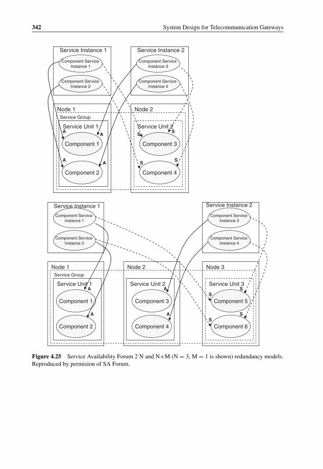
P1: OTA/XYZ P2: ABCc04 BLBK307-Bachmutsky September 2, 2010 13:18 Printer Name: Yet to Come
342 System Design for Telecommunication Gateways
Node 1 Node 2Service Group
Service Unit 1 Service Unit 2
Component 1
Component 2
Component 3
Component 4
A
A
S
S
Component Service Instance 1
Service Instance 1
Component Service Instance 3
Service Instance 2
Component Service Instance 4
A
A
S
S
Component Service Instance 2
Node 1 Node 2Service Group
Service Unit 1 Service Unit 2
Component 1
Component 2
Component 3
Component 4
Node 3
Service Unit 3
Component 5
Component 6
A
A
A
A
SS
S
Component Service Instance 1
Service Instance 1
Component Service Instance 3
Service Instance 2
Component Service Instance 2
Component Service Instance 4
S
Figure 4.25 Service Availability Forum 2 N and N+M (N = 3, M = 1 is shown) redundancy models.Reproduced by permision of SA Forum.

P1: OTA/XYZ P2: ABCc04 BLBK307-Bachmutsky September 2, 2010 13:18 Printer Name: Yet to Come
Software Technologies and Platforms 343
Node 1 Node 2 Node 3
Service Group
Service Unit 1 Service Unit 2 Service Unit 3
Component 2
A
AS
S
S
S
Service Instance 1 Service Instance 2
Component Service Instance 1
Component 1 Component 3 Component 5
Component 4Component 6
Component Service Instance 2
Figure 4.26 N-way redundancy model. Reproduced by permision of SA Forum.
and Component Service Instances, with the letters ‘A’ and ‘S’ indicating the correspondingactive or standby assignment.
� 2 N, or 1:1, redundancy model (see Figure 4.25, upper diagram) with a single standbyassignment for every active one; all active components form an active Service Unit, allstandby components form a standby Service Unit.
� N+M redundancy model (see Figure 4.25, lower diagram), where M standby componentsprotect N active ones. For the sake of completeness of terminology and to avoid anyconfusion, it makes sense to mention also the N+M vs. N:M protection scheme used by, forexample, Cisco Systems.30 The difference is that in the Cisco Systems N+M configurationboth active and standby components receive the same events (such as an incoming data), butonly the active one is processing them; the standby component performs processing onlyas and when the active component fails; this scheme is used, for example, to ensure zerodata loss after the failure in schemes such as SONET/SDH APS. In the Cisco Systems N:Mscenario only active components receive the data. The SA Forum defined only the N+Mterm and both implementations would look exactly the same from the AMF point of view.
� N-way redundancy model (see Figure 4.26). This extends the N+M model, enabling aservice unit to have simultaneously active and standby assignments for Component ServiceInstances of different Service Instances. It has the advantage that all service units can be used
30 http://www.ciscopress.com/articles/article.asp?p=361409&seqNum=5.

P1: OTA/XYZ P2: ABCc04 BLBK307-Bachmutsky September 2, 2010 13:18 Printer Name: Yet to Come
344 System Design for Telecommunication Gateways
to provide active service for some service instances while still providing standby protectionfor others. Every service instance may have zero, one or multiple standby assignments andthe number of standby assignments may differ for each service instance.
4.2.1.2 Boot Manager
The boot manager is a base of any embedded system. It is the first software running whenany system starts (actually, the first software running in many systems is a BIOS, but this canbe considered as a part of the boot manager) and it is responsible for loading the rest of thesoftware and firmware for all system components. There are multiple boot managers on themarket, some are commercial, others are open source or home-grown designs, some supportspecific processor architecture or operating system and others are more generic. Examples ofsuch boot managers include Linux Loader31 (LILO) for loading of x86-based Linux images,GRand Unified Bootloader32 (GRUB) from the respectable GNU community, SysLinux33
(includes PxeLinux for network boot, IsoLinux for CDROM boot, ExtLinux, and MemDisk),Gujin34 , Redboot35 , YAMON36 and others. For example, YAMON supports the followingfeatures:
� Run-time detection of the specific board and CPU.� Support for both little and big-endian modes with the run-time endianness detection.� Run-time detection of the available memory and its configuration.� PCI auto-detection and auto-configuration if the PCI is included� Application load using serial ports or Ethernet.� Traditional shell commands (load, go, dump, etc.) with command line history and editing
functionality.� Remote GDB debugging capability over a serial port.� Floating point emulator.� BIOS-like functionality using a vector-based call interface.
However, one of the most popular choices in telecommunication embedded products isanother open source and patent-free boot manager called Das U-boot37 and there are manypublications that cover it; one of them being [Middleware-Boot-Hallinan].
In complex systems boot is a non-trivial multi-level software loading process. Some systemcomponents are started using a distinct BIOS program loaded from ROM or EPROM andperforming Power On Self Test (POST), which includes hardware initialization and testing ofthe related subsystems (chipsets, memories, etc.) for correct behavior; selection of the nextstage boot process device (flash memory, flash disk, CDROM, hard disk, network, etc.) withor without the capability to intervene during the boot into the selection decision; running the
31 http://www.tldp.org/HOWTO/LILO.html.32 http://www.gnu.org/software/grub/.33 http://www.syslinux.zytor.com/wiki/index.php/The_Syslinux_Project.34 http://www.gujin.sourceforge.net/.35 http://www.sourceware.org/redboot/.36 http://www.mips.com/products/processors/system-software/yamon/.37 http://www.denx.de/wiki/U-Boot.

P1: OTA/XYZ P2: ABCc04 BLBK307-Bachmutsky September 2, 2010 13:18 Printer Name: Yet to Come
Software Technologies and Platforms 345
secondary BIOS programs for other components (one example is when in a familiar desktopenvironment the CPU BIOS starts graphics and networking BIOS); loading, validating andstarting the selected next stage software; and providing a basic access to hardware resources(interrupts, registers) for that loaded software.
The next level(s) (optionally combined with the first level) can also be an intermediatestep in some systems. One example of such a second intermediate step is the PC boot sectorprogram, which is only up to 512 bytes in size. The main job for the boot sector program is toselect the next boot sector program from one of the existing system partitions to be able to loadmultiple operating system images (sometimes, it even enables intervention in the selectionduring a boot, as in LILO boot manager) and continue the chaining until the ‘real’ bootloaderis loaded, validated and started. In most embedded designs, as opposed to the classical PCBIOS-based loading, the bootloader overwrites any previously loaded software and providesall services to other programs if required.
The bootloader can include a user interface for additional configuration or come withoutit, being either hard-coded (configured during the compilation time using the architecture andboard specific header files together with a set of required functionalities, as in the case of theU-Boot) or configurable using special configuration files read either at the installation, or aboot time. The program can be relatively small such as LILO or large like GRUB and its mainjob is to load the operating system’s kernel program. It is highly recommended to use oneof available bootloaders as a base and modify it if needed instead of creating a bootloaderfrom scratch, because the bootloader core is a complex and hardware-specific assembly-written code and component vendors usually provide an already modified bootloader codeapplicable to their hardware with correct starting address, image layout, configuration, etc.Also, third party COTS boards usually come with a ready-made bootloader; however, customboard creation requires some integration and development work for a bootloader supportingall board components.
Good bootloader design enables loading the OS kernel from a variety of sources in a pre-configured priority order. For example, it can try to load the image from the flash disk and ifthe load is unsuccessful for any reason (for example, corrupted file system or flash disk is notinstalled), then attempt to load from the hard disk and if this load is also unsuccessful, thentry to load from the network. The hierarchical load provides flexible, high performance andhighly reliable image start. The networking portion should include protocols such as BootstrapProtocol (BOOTP) and Dynamic Host Control Protocol (DHCP) to obtain the IP address andthe required IP configuration (for example, the default gateway IP address) from the network,and some file transfer protocol, such as Trivial File Transfer Protocol (TFTP), to receive therequired image from the configured network server.
One of the significant design complexities from a bootloader point of view is when theboard includes multiple components to load the software. One way to solve the problem isto create a chain of booting components, starting with the ‘master’ device, which will loadthe next one or pass control of the load to the next one. However, the chained boot processmight become too slow. For example, in a highly reliable system the boot time is very critical,because it defines the service outage time, meaning that in large systems with a chained bootthe way to achieve high availability is through active-standby redundancy, where a standby isalways ready to take over and a boot time is not a bottleneck. There is a more advanced andmore complex method of booting the multiple devices: loading components in parallel. Thecomplexity is in the sharing of the external buses and devices. An example of such a solution

P1: OTA/XYZ P2: ABCc04 BLBK307-Bachmutsky September 2, 2010 13:18 Printer Name: Yet to Come
346 System Design for Telecommunication Gateways
is shown in Figure 3.1 for the Advantech NCP-5120 with dual Cavium Networks OCTEONCPUs. It is easy to see that both CPUs have their own boot flash, but share the Compact Flashand the networking configuration bus, and access to these devices is provided through theon-board CPLD which can perform the device and bus access arbitration functions and whichcan be viewed as a kind of partial hypervisor (virtualization layer) for a bootloader. This is aclever design that could speed up boot time significantly.
Some multicore CPUs may enable parallel download of different images to their corre-sponding cores or sets of cores; however, in many existing multicore implementations there isa master core that boots first and then loads images for the rest of cores and in such scenarioboot management becomes a part of the Software Manager (see Section 4.2.1.6) rather than abootloader.
Another important issue during the boot process is to preserve some memory area with all ofthe information from the time the system has been restarted. Such special memory is used fordebugging purposes and can include the tracing information, some counters, critical alarms,memory dump and other data structures that can help in the critical failure debugging.
4.2.1.3 Messaging Services – Inter-Thread, Inter-Process, Inter-VM, Inter-Core,Inter-Processor, Inter-Blade and Inter-Chassis communication
Messaging services represent one of the most crucial middleware functions in an embeddedreal-time system. In many telecommunication (and not only telecommunication) systems themessaging services have to support multiple communication paths simultaneously and use themost optimal implementation for a particular path:
� Inter-Thread Communication.This communication is performed between software threads of the same process. It can beinitiated, for example, between different functions of the application or different paths of thesame function. The main property of this scenario is that threads within the same processshare memory space, meaning that the shared memory approach is potentially the mostefficient method of communication.
It is important that the entire communication is done within the user space, becauseper-message transitions between user and kernel spaces would severely affect messagingperformance.
Inter-thread communication includes the case when the threads belong to physicallyseparate cores or even processors when these processors are operating in a cache coherencymode. The problem in such scenarios is that the latency and performance of the messagedelivery may vary and the message within the same core might be more efficient becausethe data is in the cache already, which might not be the case between cores or processors.It creates the design challenge of trying to place the heavily communicating modules in thefollowing order of priority:(a) On the same core to have a data in L1 cache or other low latency shared memory, such
as a scratchpad.(b) On cores or hardware threads sharing the same L2 cache.(c) On cores or hardware threads sharing the same L3 cache if such exists.(d) On cores or hardware threads without shared cache but with shared memory.

P1: OTA/XYZ P2: ABCc04 BLBK307-Bachmutsky September 2, 2010 13:18 Printer Name: Yet to Come
Software Technologies and Platforms 347
These priorities also apply for other types of communication.� Inter-Process Communication.
This type of messaging serves well the communication needs between different applications.The difference with the inter-thread use case is that usually processes have separate memoryspaces protected from each other’s access. There are some signs that the next generationof processors might include hardware acceleration of such messaging. Actually, it existseven today in some products, such as the Cavium Networks‘ OCTEON family of multicoreprocessors (see the detailed description in Section 3.5.6.2.3), or the NetLogic XLP processor,or the Tilera TILEPro64; while in some implementations the number of available queuesis relatively small, the hardware can still provide a great deal of help to the messagingsubsystem.
Another software-based implementation option is to define some shared memory(mailbox) between every process and messaging service middleware, while still protect-ing processes from each other. The messages are either copied into the shared memory orcreated in the shared memory for the sender side and copied from the shared memory or readfrom the shared memory for the receiver side. Sometimes a single large mailbox is enough,but frequently a mailbox for each pair of communicating processes is used. With per-pairmailboxes, it is possible to create a better memory protection mechanism in order to ensurethat the communication between one pair of processes does not affect other communicationchannels and does not create unintended memory overwrites.
Inter-process messaging may require a mechanism to exchange information when bothprocesses are in a user space, both in a kernel space or one in a user space and another onein a kernel space.
� Inter-VM Communication.Communication between virtual machines has to involve the hypervisor services and/ordedicated hardware queues. Many hypervisors would provide such a service, but perfor-mance is usually not very high if it is a software-based implementation.
� Inter-Core Communication.This type of communication includes messaging between CPU cores or hardware threads.In general, it is not different from the inter-process type and the only reason for it to be ina separate group is that some CPUs implement dedicated hardware queues specifically fordata exchange between cores or threads. This method is not suitable for the generic SMPenvironment when any software thread or process can run on any core or hardware thread;however, it can be used efficiently when some threads or processes are either being assigneda core affinity and are running on a particular core, or alternatively are running in the AMPmode; it can also be used when different OS images have been using separate cores.
Sometimes, it is more efficient to use multiple addressable modules running on the samecore in order to ensure that the CPU is used efficiently when one of the modules becomes idlefor any reason. In such a scenario, one of the design options is to implement a single additionalmodule performing mux/demux function that receives a message from the hardware queue,identifies the target module and either moves the message to the corresponding softwarequeue or invokes a callback. In the latter case, it is highly recommended to implement thecallback function as short as possible, because it will block the processing of other messages.
� Inter-Processor Communication.This scenario can become relevant when there are multiple processing elements locatedon the same blade with any kind of physical and/or logical communication between them,
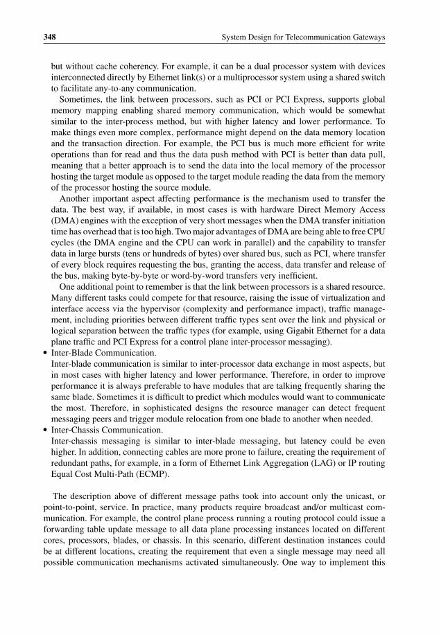
P1: OTA/XYZ P2: ABCc04 BLBK307-Bachmutsky September 2, 2010 13:18 Printer Name: Yet to Come
348 System Design for Telecommunication Gateways
but without cache coherency. For example, it can be a dual processor system with devicesinterconnected directly by Ethernet link(s) or a multiprocessor system using a shared switchto facilitate any-to-any communication.
Sometimes, the link between processors, such as PCI or PCI Express, supports globalmemory mapping enabling shared memory communication, which would be somewhatsimilar to the inter-process method, but with higher latency and lower performance. Tomake things even more complex, performance might depend on the data memory locationand the transaction direction. For example, the PCI bus is much more efficient for writeoperations than for read and thus the data push method with PCI is better than data pull,meaning that a better approach is to send the data into the local memory of the processorhosting the target module as opposed to the target module reading the data from the memoryof the processor hosting the source module.
Another important aspect affecting performance is the mechanism used to transfer thedata. The best way, if available, in most cases is with hardware Direct Memory Access(DMA) engines with the exception of very short messages when the DMA transfer initiationtime has overhead that is too high. Two major advantages of DMA are being able to free CPUcycles (the DMA engine and the CPU can work in parallel) and the capability to transferdata in large bursts (tens or hundreds of bytes) over shared bus, such as PCI, where transferof every block requires requesting the bus, granting the access, data transfer and release ofthe bus, making byte-by-byte or word-by-word transfers very inefficient.
One additional point to remember is that the link between processors is a shared resource.Many different tasks could compete for that resource, raising the issue of virtualization andinterface access via the hypervisor (complexity and performance impact), traffic manage-ment, including priorities between different traffic types sent over the link and physical orlogical separation between the traffic types (for example, using Gigabit Ethernet for a dataplane traffic and PCI Express for a control plane inter-processor messaging).
� Inter-Blade Communication.Inter-blade communication is similar to inter-processor data exchange in most aspects, butin most cases with higher latency and lower performance. Therefore, in order to improveperformance it is always preferable to have modules that are talking frequently sharing thesame blade. Sometimes it is difficult to predict which modules would want to communicatethe most. Therefore, in sophisticated designs the resource manager can detect frequentmessaging peers and trigger module relocation from one blade to another when needed.
� Inter-Chassis Communication.Inter-chassis messaging is similar to inter-blade messaging, but latency could be evenhigher. In addition, connecting cables are more prone to failure, creating the requirement ofredundant paths, for example, in a form of Ethernet Link Aggregation (LAG) or IP routingEqual Cost Multi-Path (ECMP).
The description above of different message paths took into account only the unicast, orpoint-to-point, service. In practice, many products require broadcast and/or multicast com-munication. For example, the control plane process running a routing protocol could issue aforwarding table update message to all data plane processing instances located on differentcores, processors, blades, or chassis. In this scenario, different destination instances couldbe at different locations, creating the requirement that even a single message may need allpossible communication mechanisms activated simultaneously. One way to implement this

P1: OTA/XYZ P2: ABCc04 BLBK307-Bachmutsky September 2, 2010 13:18 Printer Name: Yet to Come
Software Technologies and Platforms 349
Figure 4.27 QuickSilver Scalable Multicast architecture. Reproduced by permission of Cornell Uni-versity.
functionality is to use a native broadcast or multicast transport; however, reliability makesit more complex requiring special reliable multicast protocols. One of such protocols is theReliable Multicast Transport Protocol (RMTP).38 Other options include the Scalable ReliableMulticast (SRM) and the negative acknowledge-based Pretty Good Multicast, renamed as thePragmatic General Multicast (PGM).39 PGM relies on intermediate help from the protocol-aware routers and might not be relevant or efficient for many of the communication schemesdescribed above.
An interesting option might be QuickSilver Scalable Multicast (QSM),40 which is targetedat communication in a distributed computing environment and was developed at CornellUniversity. It is designed to support multi-group configurations and the traffic aggregationwith overlapping groups (see Figure 4.27). QSM introduces the Global Membership Service(GMS), which is responsible for nodes registration, affiliation and health management; andmulticasting is achieved by using a single IP multicast message per destination region.
Another method, used more frequently because of its simplicity, is to replicate the messageas many times as needed (per destination) and send each to its own destination as a unicasttransaction. While most network processors and practically all switches do have a specialhardware-accelerated method of packet replication, this is not the case with general purposeCPUs, which are often used for messaging.
38 http://www.cisco.com/web/about/ac123/ac147/archived_issues/ipj_1–2/reliable_multicast.html.39 See IETF RFC 3208 and http://research.microsoft.com/pubs/68888/pgm_ieee_network.pdf.40 http://www.cs.cornell.edu/projects/quicksilver/ and http://portal.acm.org/citation.cfm?id=1443222.1443605.
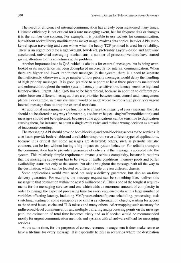
P1: OTA/XYZ P2: ABCc04 BLBK307-Bachmutsky September 2, 2010 13:18 Printer Name: Yet to Come
350 System Design for Telecommunication Gateways
The need for efficiency of internal communication has already been mentioned many times.Ultimate efficiency is not critical for a rare messaging event, but for frequent data exchangesit is the number one concern. For example, it is possible to use sockets for communication,but without socket library modifications socket usage involves data copies, heavier APIs, user-kernel space traversing and even worse when the heavy TCP protocol is used for reliability.There is an urgent need for a light-weight, low-level, preferably Layer 2-based and hardwareaccelerated, universal messaging mechanisms; a number of processor vendors have startedgiving attention to this sometimes acute problem.
Another important issue is QoS, which is obvious for external messages, but is being over-looked or its importance has been downplayed incorrectly for internal communication. Whenthere are higher and lower importance messages in the system, there is a need to separatethem efficiently, otherwise a large number of low priority messages would delay the handlingof high priority messages. It is good practice to support at least three priorities maintainedand enforced throughout the entire system: latency-insensitive low, latency-sensitive high andlatency-critical urgent. Also, QoS has to be hierarchical, because in addition to different pri-orities between different messages, there are priorities between data, control and managementplanes. For example, in many systems it would be much worse to drop a high priority or urgentinternal message than to drop the external user data.
An additional messaging service function is to ensure the integrity of every message: the datashould not be altered in any way (for example, a software bug causing buffer modification); andmessages should not be duplicated, because some applications can be sensitive to duplicationcausing them, for instance, to count a single event twice and make a wrong decision as a resultof inaccurate counting.
The messaging API should provide both blocking and non-blocking access to the services. Italso has to provide both reliable and unreliable transport to serve different types of applications,because it is critical that some messages are delivered; others, such as periodic statisticcounters, can be lost without having a big impact on system behavior. For reliable transportthe communication has to provide a guarantee of delivery if the message is accepted into thesystem. This relatively simple requirement creates a serious complexity, because it requiresthat the messaging subsystem has to be aware of traffic conditions, memory pools and bufferavailability status not only at the source, but also throughout the message path all the way tothe destination, which can be located on different blade or even different chassis.
Some applications would even need not only a delivery guarantee, but also an on-timedelivery guarantee. For example, the message request can be something like, ‘deliver thismessage to that destination within the next 5 milliseconds’. This is one of the toughest require-ments for the messaging services and one which adds an enormous amount of complexity inorder to manage the expected processing time for every enqueued data with a large number ofvariables affecting latency, including VM/process/thread/queue scheduling, processing, taskswitching, waiting on some semaphores or similar synchronization objects, waiting for accessto the shared buses, cache and TLB misses and many others. After mapping such accuracy formillisecond-level communication and multiple buffering and processing points on the messagepath, the estimation of total time becomes tricky and so if needed would be recommendedmostly for urgent communication methods and systems with a hardware offload for messagingservices.
At the same time, for the purposes of correct resource management it does make sense tohave a lifetime for every message. It is especially helpful in scenarios where the destination

P1: OTA/XYZ P2: ABCc04 BLBK307-Bachmutsky September 2, 2010 13:18 Printer Name: Yet to Come
Software Technologies and Platforms 351
module had died and the message can never be delivered, or when a priority between queuesand the scheduling algorithm causes one of them to starve and keep messages enqueued for toolong a time, unnecessarily blocking potentially expensive system resources. Having a lifetimewould allow the garbage collection mechanism to walk through all message queues and cleanthem with or without message originator notification.
Another interesting topic is the scope of acknowledgement for a reliable message. Inmost implementations only end-to-end acknowledgement is considered. This might limit theperformance of some applications significantly. For example, in active-standby redundancythere is a need for extensive communication between active and standby peers (processors,blades, or even separate physical boxes in network-based redundancy). On the other hand,for an active application to continue processing, the most important information is that thestandby has received the message and not processed it; the processing can be done later, butthis ensures that the data will not be lost if the active fails after that. It would mean that the mostimportant event for such a message from an active to standby entity would be the fact that thedata has crossed the boundary between them and is in some receiving buffer on standby, suchas a networking driver buffer, as opposed to the target application buffer. To make this happen,there is sometimes a need for both hop-by-hop and end-to-end acknowledgement. With such acapability being implemented, an example of state synchronization between active and standbyblades (let us assume that the blades are interconnected by an Ethernet link for the purpose ofour example) would look as follows:
1) An active application sends a state synchronization message to its standby peer on the otherblade.
2) The message arrives to the Ethernet driver on an active blade and is sent over the Ethernetto a standby entity.
3) The message is received by the standby blade’s Ethernet driver and the receipt isacknowledged immediately to its active Ethernet driver peer.
4) The active Ethernet driver peer updates the data latest known location being in the standbyEthernet driver buffer.
5) The active application can continue its processing immediately without waiting for thestandby application’s acknowledgement.
6) The data arrives to the standby application and is processed as needed.7) The standby application sends the final acknowledgement (if requested) to the active
application.
In the sequence described above there can be a relatively long time elapsed between steps5 and 7, which enables a much earlier resumption of normal active application functionality.It becomes especially critical when there are many synchronization points in the system.
Another important requirement for internal communication is the prevention of head-of-the-line blocking. In practice, this means that if data cannot be delivered to a particular destination(for example, a physical link has failed, or the target port is signalled by a flow control todelay the traffic), it must not prevent this message from being delivered to other destinations orother messages behind it in the queue being delivered to any destination. In the latter case, themessage can be blocked because of the overflow of one of the queues and there is no reasonto block any other message targeted at another queue even at the same destination module.

P1: OTA/XYZ P2: ABCc04 BLBK307-Bachmutsky September 2, 2010 13:18 Printer Name: Yet to Come
352 System Design for Telecommunication Gateways
In some applications it can be useful to be able to revoke the previously sent message. It issimilar to e-mail withdrawal, applicable only when the message has not yet been processed bythe destination application and can be used in a rapidly changing situation when the messagebecomes incorrect or irrelevant shortly after being sent.
In many systems there are many simultaneously active messages at different stages ofdelivery and processing. The message service has to have detailed debugging capabilitiesenabling it to check statistics, the status of service and its components, make a snapshot ofa state and check the status of any message in that snapshot. There can be also a tracingmechanism, but in a system with a high rate of messages the tracing can bring too heavyan overhead to be considered for troubleshooting because of the significant system timingchanges with the tracing feature turned on.
One of the challenges for messaging middleware is to provide seamless behavior and asingle API without exposing the peers’ location and a type/class of service. This is one of themain areas where the industry lacks open standards and simplified integration. There is anurgent need for a real-time communication API as open and as ubiquitous as the socket API.
A partial answer to this need could be the Transparent Inter-Process Communication (TIPC)protocol enabling applications in a clustered configuration to communicate with other appli-cations, regardless of their location within the cluster. The TIPC was developed originally byEricsson and included in multiple products; at some point of time Ericsson made the deci-sion to open up the entire protocol to the community, which instigated the TIPC open sourceproject.41 The main TIPC properties include the following:
� Location transparency, as already mentioned above.� Auto-discovery mechanism and the link maintenance.
Every TIPC node broadcasts Link Request messages periodically on all configured inter-faces. If this message is received by a node with no prior established link to the sendingnode, it replies with a unicast Link Response message, which leads to the link, or connection,between a given pair of nodes. The link also has a keepalive concept with periodic messagessent to continue to maintain the link and detect link failure. These keepalive messages carryan additional functionality by containing an acknowledgement of the last received 16-bitsequence number, in order to allow the receiver to release sent packet buffers kept in the sentqueue and used for packet retransmission in a reliable communication scenario; these mes-sages also include a last sent 16-bit sequence number, allowing the receiver to detect packetloss. Any single message can acknowledge a number of previously received messages.
It is important to remember that the TIPC protocol does not handle any specific byteordering checks. Implementations on processors with a different ordering have to convertall messages to some common byte order, which means an additional complexity andperformance implications for either little or big endian implementations.
� Redundant links.The TIPC includes a capability to redirect messages to an available alternate link when theprimary link fails.
� Flow control and congestion control.For the purposes of flow control, both sender and receiver maintain a dedicated packetcounter per link and the receiver reports the number of messages received since the last
41 http://www.tipc.sourceforge.net/doc/tipc_1.7_prog_guide.pdf.

P1: OTA/XYZ P2: ABCc04 BLBK307-Bachmutsky September 2, 2010 13:18 Printer Name: Yet to Come
Software Technologies and Platforms 353
NodeCluster
Zone
NodeCluster
Zone
Figure 4.28 TIPC topology hierarchies. Reproduced by permission of Wikipedia.
report, which controls the sender’s transmit window: if there are too many unacknowledgedpackets, the sender stops sending packets.
� Hierarchical topology and addressing.When multiple TIPC nodes have full mesh links connectivity, meaning that there is atleast one link between any pair of TIPC nodes, they are combined logically into clusters.When multiple TIPC clusters have full mesh connectivity, they are combined logically intozones (see Figure 4.2842). The hierarchy creates a logical address for every TIPC node tobe Z.C.N, which is translated into a 32-bit unique node address used internally, where Zrepresents a zone ID, C represents a cluster ID within the zone Z, and N represents the nodeID within the cluster C. The above-mentioned 32-bit address encoding allows the singlenetwork having up to 255 zones, up to 4095 clusters in every zone, and up to 4095 nodesin every cluster. In this notation Z.C.0 indicates a network cluster, Z.0.0 indicates a networkzone, and address 0.0.0 has a special meaning depending on the context of its usage. Inaddition, each node can have multiple ports, similar to UDP/TCP ports, but each TIPC portnumber has a unique 32-bit ID, which brings the communicating TIPC port identifier to a64-bit value with a notation of Z.C.N:port. Server ports in TIPC have names assigned tothem in a form of {type,instance}, where each 32-bit field can be defined by the applicationand, unlike the port ID, does not have to be unique. Name binding to the port includes thename scope (node, cluster or zone), and the uniqueness is required only within that scope.The TIPC specification supports a definition of a range of port instances from the sametype, which can be from {type,lower-bound} to {type,upper-bound}, or for simplicity just{type,lower-bound,upper-bound}.
Applications can also register with the TIPC for notifications about port names bind/unbindoperations. Such subscription may be made with a timeout value assigned to it.
42 http://en.wikipedia.org/wiki/TIPC.
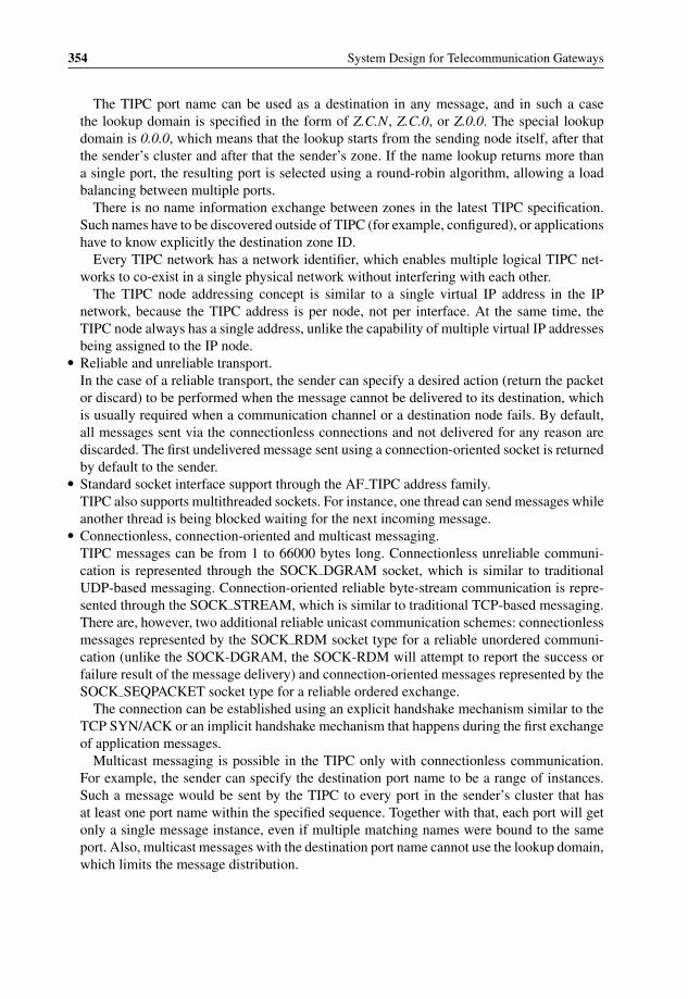
P1: OTA/XYZ P2: ABCc04 BLBK307-Bachmutsky September 2, 2010 13:18 Printer Name: Yet to Come
354 System Design for Telecommunication Gateways
The TIPC port name can be used as a destination in any message, and in such a casethe lookup domain is specified in the form of Z.C.N, Z.C.0, or Z.0.0. The special lookupdomain is 0.0.0, which means that the lookup starts from the sending node itself, after thatthe sender’s cluster and after that the sender’s zone. If the name lookup returns more thana single port, the resulting port is selected using a round-robin algorithm, allowing a loadbalancing between multiple ports.
There is no name information exchange between zones in the latest TIPC specification.Such names have to be discovered outside of TIPC (for example, configured), or applicationshave to know explicitly the destination zone ID.
Every TIPC network has a network identifier, which enables multiple logical TIPC net-works to co-exist in a single physical network without interfering with each other.
The TIPC node addressing concept is similar to a single virtual IP address in the IPnetwork, because the TIPC address is per node, not per interface. At the same time, theTIPC node always has a single address, unlike the capability of multiple virtual IP addressesbeing assigned to the IP node.
� Reliable and unreliable transport.In the case of a reliable transport, the sender can specify a desired action (return the packetor discard) to be performed when the message cannot be delivered to its destination, whichis usually required when a communication channel or a destination node fails. By default,all messages sent via the connectionless connections and not delivered for any reason arediscarded. The first undelivered message sent using a connection-oriented socket is returnedby default to the sender.
� Standard socket interface support through the AF TIPC address family.TIPC also supports multithreaded sockets. For instance, one thread can send messages whileanother thread is being blocked waiting for the next incoming message.
� Connectionless, connection-oriented and multicast messaging.TIPC messages can be from 1 to 66000 bytes long. Connectionless unreliable communi-cation is represented through the SOCK DGRAM socket, which is similar to traditionalUDP-based messaging. Connection-oriented reliable byte-stream communication is repre-sented through the SOCK STREAM, which is similar to traditional TCP-based messaging.There are, however, two additional reliable unicast communication schemes: connectionlessmessages represented by the SOCK RDM socket type for a reliable unordered communi-cation (unlike the SOCK-DGRAM, the SOCK-RDM will attempt to report the success orfailure result of the message delivery) and connection-oriented messages represented by theSOCK SEQPACKET socket type for a reliable ordered exchange.
The connection can be established using an explicit handshake mechanism similar to theTCP SYN/ACK or an implicit handshake mechanism that happens during the first exchangeof application messages.
Multicast messaging is possible in the TIPC only with connectionless communication.For example, the sender can specify the destination port name to be a range of instances.Such a message would be sent by the TIPC to every port in the sender’s cluster that hasat least one port name within the specified sequence. Together with that, each port will getonly a single message instance, even if multiple matching names were bound to the sameport. Also, multicast messages with the destination port name cannot use the lookup domain,which limits the message distribution.

P1: OTA/XYZ P2: ABCc04 BLBK307-Bachmutsky September 2, 2010 13:18 Printer Name: Yet to Come
Software Technologies and Platforms 355
� Subscription to network events.� Particular design optimization points.
While the TIPC can be used for a wide range of communication between different softwaremodules in the system, it was designed with a number of assumptions affecting its usageefficiency:– Multi-hop communication is relatively rare.– The medium transfer time and the packet loss rate are relatively negligible.– The number of nodes in the system is not changing rapidly and significantly.– There is no need for secured communication.– The majority of communication needs are between nodes that belong to the same cluster,
meaning that each node will communicate most frequently with other nodes in its owncluster, relatively infrequently with nodes in other clusters in its own zone and almostnever with nodes in other zones.
There are TIPC implementations for multiple languages, such as C/C++, Perl, Python,Ruby and D, and for multiple operating systems, including VxWorks (from version 6.1),Linux (from kernel version 2.6.16), Solaris (from version 10 update 4) and OpenSolaris (from2008.05).
Unfortunately, there is a significant difference today between generic TIPC capabilities andexisting implementations. For example, the major communication channel between differentnodes is frequently assumed to be Ethernet, with a shared memory approach available onlyfor VxWorks in systems that have a capability to configure a subset of the entire memory tobe shared between nodes. In many implementations, the TIPC transport layer utilizes the TCPwith a potentially significant impact on performance.
Another messaging specification comes from the Multicore Association, the Multicore As-sociation’s Communication API (MCAPI).43 The source of the standard specification definesmessaging within a closely-distributed multicore environment. The main idea behind this fo-cus is that multicore communication can offer high performance levels (low latency and highthroughput) and the multicore environment is sensitive to the software footprint because ofcache architectures and the cost associated with an embedded system memory. Therefore,high performance and low footprint are two major properties of MCAPI, which is differentfrom TIPC which focuses more on flexible functionality and the widely-distributed systemapproach.
The communication with MCAPI is performed between MCAPI nodes, which are definedas logical entities in the system by calling the mcapi initialize() API function and specifyinga unique domain and node IDs. An MCAPI node can be a thread, process, OS instance,core, offload engine and similar software or hardware elements, with thread being a highestgranularity; it is assumed that a single execution thread hosts at most a single MCAPI node.Each node can have multiple socket-like communication endpoints defined by three tuples<domain id, node id, port id>. While the MCAPI topology can be flexible by means ofrequesting a creation of the next available endpoint as opposed to stating the port identifier ex-plicitly, the existing MCAPI specification promotes the static assignment of endpoints, forcingtopology definition at a compilation time as opposed to a run-time discovery of topology. Each
43 http://www.multicore-association.org/workgroup/mcapi.php.
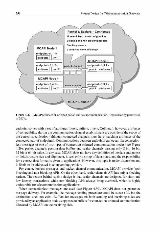
P1: OTA/XYZ P2: ABCc04 BLBK307-Bachmutsky September 2, 2010 13:18 Printer Name: Yet to Come
356 System Design for Telecommunication Gateways
attributes port 1
endpoint <1,4,1>
attributesport 2
endpoint <1,3,2>
attributes port 2
endpoint <1,1,2>
attributes port 1
endpoint <1,1,1>
MCAPI Node 1
MCAPI Node 4
attributesport 1
endpoint <1,3,1>
MCAPI Node 3
packet channel
scalar channel
MCAPI Domain 1
Packet & Scalars – Connected
More efficient, more configuration
Blocking and non-blocking packets
Blocking scalars
Connected more efficiency
Figure 4.29 MCAPI connection oriented packet and scalar communication. Reproduced by permissionof MCA.
endpoint comes with a set of attributes (pools, buffers, timers, QoS, etc.); however, attributesof compatibility during the communication channel establishment are outside of the scope ofthe current specification (although connected channels must have matching attributes of theconnected pair of endpoints). Communications between endpoints can occur via connection-less messages or one of two types of connection-oriented communication modes (see Figure4.29): packet channels passing data buffers and scalar channels passing only 8-bit, 16-bit,32-bit or 64-bit value. In any case, MCAPI does not have any definition of the data endiannessor field/structure size and alignment, it sees only a string of data bytes, and the responsibilityfor a correct data format is given to applications. However, this topic is under discussion andis likely to be addressed in an upcoming revision.
For connectionless messages and packet channel communication, MCAPI provides bothblocking and non-blocking APIs. On the other hand, scalar channels API has only a blockingvariant. The reason behind such a design is that scalar channels are designed for short andlow latency transactions, while non-blocking APIs always bring overhead, which is highlyundesirable for telecommunication applications.
When connectionless messages are used (see Figure 4.30), MCAPI does not guaranteemessage delivery. For example, the message sending procedure could be successful, but thedestination does not exist. Buffers for messages on both sending and receiving sides areprovided by an application node as opposed to buffers for connection-oriented communicationallocated by MCAPI on the receiving side.
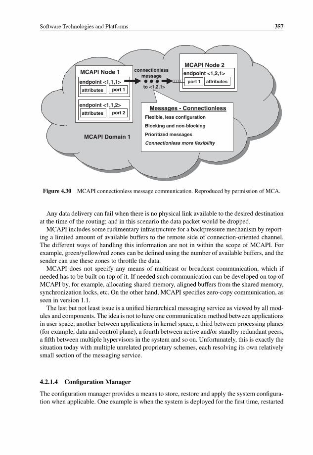
P1: OTA/XYZ P2: ABCc04 BLBK307-Bachmutsky September 2, 2010 13:18 Printer Name: Yet to Come
Software Technologies and Platforms 357
attributes port 2
endpoint <1,1,2>
attributes port 1
endpoint <1,1,1>
MCAPI Node 1
attributesport 1
endpoint <1,2,1>
MCAPI Node 2connectionless
message
MCAPI Domain 1
Messages - ConnectionlessFlexible, less configuration
Blocking and non-blocking
Prioritized messages
Connectionless more flexibility
to <1,2,1>
Figure 4.30 MCAPI connectionless message communication. Reproduced by permission of MCA.
Any data delivery can fail when there is no physical link available to the desired destinationat the time of the routing; and in this scenario the data packet would be dropped.
MCAPI includes some rudimentary infrastructure for a backpressure mechanism by report-ing a limited amount of available buffers to the remote side of connection-oriented channel.The different ways of handling this information are not in within the scope of MCAPI. Forexample, green/yellow/red zones can be defined using the number of available buffers, and thesender can use these zones to throttle the data.
MCAPI does not specify any means of multicast or broadcast communication, which ifneeded has to be built on top of it. If needed such communication can be developed on top ofMCAPI by, for example, allocating shared memory, aligned buffers from the shared memory,synchronization locks, etc. On the other hand, MCAPI specifies zero-copy communication, asseen in version 1.1.
The last but not least issue is a unified hierarchical messaging service as viewed by all mod-ules and components. The idea is not to have one communication method between applicationsin user space, another between applications in kernel space, a third between processing planes(for example, data and control plane), a fourth between active and/or standby redundant peers,a fifth between multiple hypervisors in the system and so on. Unfortunately, this is exactly thesituation today with multiple unrelated proprietary schemes, each resolving its own relativelysmall section of the messaging service.
4.2.1.4 Configuration Manager
The configuration manager provides a means to store, restore and apply the system configura-tion when applicable. One example is when the system is deployed for the first time, restarted

P1: OTA/XYZ P2: ABCc04 BLBK307-Bachmutsky September 2, 2010 13:18 Printer Name: Yet to Come
358 System Design for Telecommunication Gateways
for any reason or reconfigured while being in-service. The new configuration can be eitherpushed into the system, usually from the management layer, or pulled by the system from apre-configured external server. The configuration can be presented as one single file with allparameters included or as a set of configuration files grouped by components, devices, func-tions or other principles. Configuration files in the set can be organized in a hierarchy, whenthe higher file in the hierarchy includes references to the next hierarchy level configuration(s).For instance, the main system configuration file could include a reference to functional con-figurations, which in turn include specific software and hardware components configurations.Also, some sets of configuration parameters can be modified using management procedures,such as CLI commands and scripts or SNMP messages.
Deployed and committed configurations are usually stored in a local or network-basedpersistent storage, such as NVRAM, flash or hard disk. Storage file formats are either binaryor text-based and they vary from a fully proprietary to files coded, for example, in AbstractSyntax Notation One44 (ASN.1) or eXtensible Markup Language (XML).
The configuration manager maintains different types of configuration which can be dividedinto the following groups:
� Running configuration that includes all system committed and uncommitted parameters.For example, a single configuration set may include many related parameters with complexdependencies between them. The modification of these parameters cannot be fully atomic;therefore, there is a time period when some values have been configured already, whileothers are still awaiting their turn. Sometimes, failure of one of intermediate configurationcan invalidate many previous ones, creating a need for intermediate restore points, whichinclude fully committed and potentially some still uncommitted parameters and rollbacks tothese restore points. Implementation of running configuration restore points can be viewedas the capability of having multiple running configurations and switching at the run-time toany arbitrary configuration.
� Current configuration that contains the last committed system configuration parameters.� Backup configuration with committed system configuration parameters. It is used when the
current configuration cannot be read, authenticated or verified.� Custom configurations with committed system configuration parameters that can be used to
switch between different features, interworking and other scenarios.� Factory default configuration which represents the last resort of recovery from the unintended
system misconfiguration.
All of the above configurations can be software independent, hardware independent ormanaged as a function of software or hardware release. Taking into account the fact that asingle system may include, for example, boards with different hardware versions and softwarepackages, configuration management can become a complex and multi-dimensional task.
When the system starts, many software modules would try to load their correspondingcurrent configuration. It can be done sequentially as shown in Figure 4.31, but parallel config-uration retrieval is preferable; a hierarchy of configurations is also frequently used when thereare module interdependencies.
44 http://www.asn1.org/.

P1: OTA/XYZ P2: ABCc04 BLBK307-Bachmutsky September 2, 2010 13:18 Printer Name: Yet to Come
Software Technologies and Platforms 359
System starts
System Initialization
Module 1 requests the configuration
Module 2 requests the configuration
Module N requests the configuration
Configuration Manager has initialized, reads all the configuration files and waits for request
from different modules for get/set/save/backup
Configuration Manager
Figure 4.31 Sequential configuration retrieval during the system start.
If any module cannot perform the initial configuration after restart, the problem is reportedto the resource manager and such module can be declared as failed. Depending on the failedmodule, the resource manager can decide that the whole system cannot continue to functionproperly followed by a forced restart with backup configuration if one exists. If the failurepersists, the system is restarted with both the backup image and backup configuration and ifthe failure still persists, the system will be declared as failed to start with a corresponding fatalerror report to the management layer.
However, external dependencies should not be considered as a configuration failure. Forexample, the configuration may include connectivity to one or more external devices, whichcould be unreachable at that particular time, which should not prevent the application fromstarting. A similar principle is also applicable to license limitation: an application configurationshould be successful even if the license does not allow it; license management has to beseparated from configuration management.
When the running configuration is modified, it rarely becomes committed automatically,because the configuration commitment involves many aspects of not only correctness ofbehavior of the system in question, but also its interworking with other systems. In most casesit is the operator who makes the final configuration commitment. When this happens, thecurrent configuration is marked as a backup configuration and the running configuration isstored in the persistent storage as a current one. Usually, the system supports the means of the

P1: OTA/XYZ P2: ABCc04 BLBK307-Bachmutsky September 2, 2010 13:18 Printer Name: Yet to Come
360 System Design for Telecommunication Gateways
operator saving and restoring any configuration into/from the persistent storage and markingit as a current or a backup. The desired behavior in the case of restoring some configuration(making it the running one) is implementation-specific and can be done theoretically in-service without the restart; however, in many cases the whole system is restarted to ensureconfiguration and behavior consistency.
One of the challenges for the configuration manager lies in the handling of multiple simulta-neous configuration sessions, especially if more than a single session tried to modify the sameconfiguration (multiple configuration reads should be permitted). It can happen when differentoperators with administrative privileges perform changes simultaneously. In this scenario thejob of the configuration manager is to detect the conflicts between operators’ commands andresolve these conflicts by denying either all of them except the one being accepted or evendenying all of them together with the corresponding error notification. To minimize conflict,some implementations provide automatic critical sections locking triggered by the first ses-sion modification attempt and causing all secondary sessions trying to access the same criticalsession to be blocked until the lock is released.
4.2.1.5 Resource Manager
The resource manager is responsible for monitoring system resources, including availablestorage space, memory, packet buffers, CPU load and others, and making decisions based onthe usage of these resources. In many systems the resource manager is used together with thehardware platform management layer (see Section 4.2.1.7) for resource discovery and access.
Many different implementations of the resource manager are possible. One example is whenup to three watermarks, green-yellow-red, can be set per resource. For each watermark thereare two limit values, one for upward crossing and one for downward crossing, and a set ofactions. The limit value is designed to include a threshold hysteresis configuration and canbe a number of consecutive resource allocations causing the threshold to be crossed in theparticular direction or a time period with a watermark being crossed. The idea of the limitvalue is to avoid a watermark crossing back and forth for every resource allocation, such as asingle buffer allocate and free operations. For many resources in high-speed real-time systemstime is not a good parameter for hysteresis measurement, because events occur very quicklyand the situation can deteriorate in a short period of time, potentially within the hysteresistimeout.
The action can include alarm generation, logging, fault generation, as well as eventposting. Further system action (application restart, system reboot, etc.) is the subscriber’sresponsibility, which can be an operator or another system module. As an example of resourcemanagement actions with three watermarks, we can take a number of users and their activesessions handled by the system. When the watermark is green, the system can accept withoutlimitations both new subscribers and new sessions. When the watermark is yellow, the sys-tem can block new subscribers but still allow the existing subscribers to open new sessions.When the red watermark level is crossed, any new subscriber or new session for the existingsubscriber is blocked.
In sophisticated implementations resource management can be not only reactive, withactions being taken when the threshold is crossed, but also proactive, when the resourcemanager detects developing trends and makes decisions based on these trends. For example,

P1: OTA/XYZ P2: ABCc04 BLBK307-Bachmutsky September 2, 2010 13:18 Printer Name: Yet to Come
Software Technologies and Platforms 361
Task1 Task2
Taskm
OS BOS AShared Memory RegionCore NCore 1Core 0
MRAPI
Resource
Figure 4.32 Multicore Association MRAPI architecture. Reproduced by permission of MCA.
the resource manager can detect the increased need for a particular resource from one of thesystem functions and can rearrange the resource allocation to accommodate such a need. Forexample, in many mobile networks the data and control plane load distribution may varyduring the day. Subscribers wake up in the morning and check their e-mails, news and othernetwork resources; at that time the data plane traffic usage jumps, while the control planestays relatively low. Later, these subscribers go to work, and the data usage goes down, butthe subscriber mobility events increase as these subscribers drive to work passing many basestations. When they arrive at work, the subscribers might start using their desktop and laptopcomputers to access the Internet as opposed to their mobile terminals in the morning; and suchbehavior would reduce both control and data plane traffic. There might be similar changes atthe lunch time and evening rush hours. Our example shows one type of a global trend anda proactive resource manager can move the processing cores or CPUs dynamically betweendata plane and control plane based on the time of the day, which becomes an especiallypowerful feature in systems with multicore processors used for both control and data planetraffic handling.
When the system resources are virtualized (for example, multiple operating systems or CPUsshare the common resources), the resource management task becomes even more complex. Insuch systems there is a need for a hierarchical resource manager, where the global manager iswatching the total system resources and is tightly connected to the hypervisor if such an entityexists, because the hypervisor is an entity that enforces shared resource usage. The next levelof resource management hierarchy would be that located in every virtual machine (VM).
The dependency between resource management and virtualization functions requires acapability to develop custom hypervisor modules and well-defined APIs between hypervisorand VMs for communication with these custom modules.
The Multicore Association has opened a working group focusing on resource managementstandardization for multicore environments (see Figure 4.32). Based on the group’s charterdefinition,45 ‘The purpose of the Multicore Resource Management API (MRAPI) is to cap-ture the essential capabilities required for managing shared resources in a closely distributed(multiple cores on a chip and/or chips on a board) embedded system. These resources includemultiple cores or chips, hardware accelerators, memory regions, and I/O. MRAPI will supportthe ability to declare and allocate/destroy shared memory regions and to identify nodes whichhave access to each region. MRAPI will also provide application-level synchronization prim-itives for coordinating access to shared resources. Additional features may include resource
45 http://www.multicore-association.org/workgroup/mrapi.php.

P1: OTA/XYZ P2: ABCc04 BLBK307-Bachmutsky September 2, 2010 13:18 Printer Name: Yet to Come
362 System Design for Telecommunication Gateways
registration and locking facilities which would allow the user to register a globally visiblenamed entity and request and release locks against it’. The first specification has been releasedfor external review. It definitely makes sense to keep track of the specification efforts and theavailability of compliant implementations.
4.2.1.6 Software Manager
The software management, or upgrade management, role in the system is to facilitate softwaredeployment to all subsystems. It is related to the bootloader described in Section 4.2.1.2 bymeans of signaling the image required to load during the boot process. The rest of this func-tionality enables software version management as well as upgrade and downgrade procedures.
Frequently, the software manager stores a number of software images for every device inthe system:
� Running image.This is the image of the software that is running currently on the device. It can be, forexample, a firmware currently loaded into a FPGA, or a Linux image loaded into a particularCPU core.
� Next image.This is the image of the software that will be running on the device after the next devicerestart. This is the image that would be signalled as a reference to the bootloader.
� Backup image.This is the image of the software that will be loaded on the device if the next image eitherfails to load or become unstable. The definition of unstable is usually product-dependent andcan vary from crashing within a configured time interval after its last restart, or a numberof crashes in a given period of time, or an image marked by the management system as‘unstable’, or some variation of these rules. Good software manager design would includeautomatic rollback of the running image to the backup image in a scenario of unstablerunning image by marking the backup image as being the next image and restarting thedevice under question.
� Custom images.These are images that can be loaded into the system by the management layer so as tobe able to switch to any given software version if needed. It may include a number ofbackup stable releases, a number of releases to be loaded for the interworking with otherdevices in the system or other systems in the network, temporary promotional releasesactivated for a pre-configured period of time and automatically reversed back when there isno commitment from the management layer within that time, different images for differenthardware configurations (especially in the case of centralized hard disk or networking boot)and many other use cases.
� One of the possible implementations of the new software load could be the following:– Download the new software image, decompress it (images are often compressed to save
storage space and/or network capacity and optimize the file transfer time), validate theimage (authenticate and verify for correctness using digital signature, checksum or similarmechanisms, together with hardware and software compatibility information, meaning

P1: OTA/XYZ P2: ABCc04 BLBK307-Bachmutsky September 2, 2010 13:18 Printer Name: Yet to Come
Software Technologies and Platforms 363
that the software manager should have an access to the device type and version), and inthe case of success mark the image as the next image
– Mark the current backup image as a secondary backup, running the image as a primarybackup image, assuming the current running image can be treated as stable.
– Restart the device or the subsystem, which will come up with the newly downloadedimage. If it becomes unstable, the system will rollback automatically to the previousversion with the loading of the primary backup image and mark it as a next image withthe secondary backup becoming the primary one. Otherwise either the software managerautomatically or through the management layer (administrator) would make the newsetting permanent.
Software manager policies can be driven by the difference between the running image andthe next image. For example, when the software version is managed using 4-level hierarchymajor.minor.revision.build, the decision made and parameters used for the decision could differif the new image represents a new major release with additional functionality and potentialbackwards compatibility issues compared to just a next build, which most probably includesonly a number of bug fixes without any new features and API or protocols modifications.
Many systems require multiple images because of multiple devices, different images forcontrol, data and management processing, etc. In these systems either the software managerreceives the image compatibility mapping, or a single downloaded image contains all ofthe required sub-images to be loaded into all devices. When this is important, the softwaremanager can receive a configuration or instructions for a particular order of device image loadand every loading stage may include a single image loaded into a single device, a single imageloaded into multiple devices or multiple images loaded into multiple devices simultaneouslydepending on system capabilities.
4.2.1.7 Hardware Manager
The hardware manager configures and monitors various hardware resources in the system,such as fans, Power Entry Modules (PEMs), temperature sensors and reporting thresholds,watchdogs, LEDs, storage devices, networking devices, processors and memories and others.For example, the hardware manager can adjust fan speed based on manual operator command orautomatically when the component or internal box temperature changes, which can be causedby a change of system load during peak hours or lower traffic night hours, failure/recovery orremoval/insertion of different boards, disks or other field-replaceable units (FRUs).
The hardware manager is also responsible for hardware diagnostics, especially when thesystem starts up. Some hardware manager implementations detect the reason for the lastshutdown and run, for example, only a limited diagnostics cycle after the graceful restart withfull diagnostics after the failure.
An additional task of the hardware management service is to enable access and/or pro-gramming of boot flash and non-volatile memory (NVRAM) with static information, such asaddresses configuration, device ID, license information, etc.
One of problems in designing the hardware management is that every hardware element isdifferent, and the complexity is shown in Figure 4.33.
The SA Forum HPI (see the description above in Section 4.2.1) solves the problem bycreating the interface between hardware and middleware. HPI becomes a de-facto standard

P1: OTA/XYZ P2: ABCc04 BLBK307-Bachmutsky September 2, 2010 13:18 Printer Name: Yet to Come
364 System Design for Telecommunication Gateways
Application
Service Availability Management Middleware
Platform DPlatform CPlatform BPlatform A
Hardware Platform A
Hardware Platform B
Hardware Platform C
Hardware Platform D
Platform Specific Interfaces
Figure 4.33 The problem of platform variety for hardware management. Reproduced by permissionof SA Forum.
and the HPI API appears frequently as a mandatory specification requirement in many newlydeveloped and even upgraded telecommunication systems. The need to abstract the hardwarecomplexities and varieties together with the availability and a good coverage of HPI spec-ification to answer most hardware platform management issues and also alignment of HPIand ATCA standards is driving this trend.In practice, it is a rare case when totally proprietaryspecification is justified.
4.2.1.8 Fault Management
The fault management service is usually built on top of either the messaging or event servicesand provides fault notifications and fault state monitoring. The service often follows thepublish-subscribe model, where module(s) detect faults in software and hardware componentsand notify the registered subscribers about these faults. Examples of such subscribers areSNMP and O&M agents communicating with network and element management layers.
In many cases the fault propagation is hierarchical: when the port status changes to DOWNstate, the server applications are notified, which in turn generates notification to their clientsand so on.
There can be multiple types of notification generated by the fault management service:
� General alarm on/off that indicates a situation requiring automatic or manual attention.� Security alarm on/off notifying about a security related condition.� State or attribute change.� Object create/delete.
One important item in handling alarms is identification of the root cause and prevention ofalarm flooding, where many secondary alarms are generated (see Figure 4.34).
One example of alarm flooding can be a port failure, where a single failed physical portcontains many failed logical ports (VLANs for Ethernet, logical channels in SPI4.2 or PCIExpress, VCs for ATM, etc.) and each logical port has its own physical IP address that also

P1: OTA/XYZ P2: ABCc04 BLBK307-Bachmutsky September 2, 2010 13:18 Printer Name: Yet to Come
Software Technologies and Platforms 365
Application 1
Application 3Application 2
Application 4 Application 7Application 6Application 5
Application 9Application 8
Figure 4.34 Alarm flooding caused by secondary fault propagation.
fails; each IP address can be a termination point of many IP tunnels going down and so on. It iseasy to see that a single port failure can create thousands or more secondary alarms overloadingthe system, network and management layers and make it complicated for an administrator tofilter a lot of information in order to find the root cause.
There are multiple ways to prevent flooding and one of them is to flag the root cause vs. asecondary cause. In some cases there is no need at all for secondary alarm generation. In othercases the internal secondary alarm is still generated (for example, the OSPF routing mightdepend on logical channel or IP address failure, rather than the entire port failure), but it issuppressed on the external/management communication.
Alarms are not always generated hierarchically, but there is still a relationship betweenthem. It can happen, for example, because of the timing of the events. An application candetect the failure of another application either directly (no response or no keepalive message),or indirectly through the availability manager or other service. These two events might cometotally independently, being flagged as a primary alarm, but they still share the same root cause;and the task of the fault management service is to identify the fact that there is a commoncause for both events and either aggregate them into a single event or suppress all of themexcept the one which will be propagated further. In most implementations it is done based onthe correlation of events’ properties. The functionality requires large buffers of the latest faultsthat can be viewed as an event cache and a comparison of every new fault parameter with thiscache so to identify the dependencies.

P1: OTA/XYZ P2: ABCc04 BLBK307-Bachmutsky September 2, 2010 13:18 Printer Name: Yet to Come
366 System Design for Telecommunication Gateways
To help prioritize all of the faults in the system, every fault is usually tagged as to its severitywith multiple levels, such as minor, major, critical, warning, etc. For example, an applicationfailure can be major or critical depending on the specific module which has failed. On the otherhand, a fan failure is critical or major depending on the redundancy mechanism, because ifthe system is designed without any protection or even with a single point of failure protection,once the fan fails the system is no longer protected, and there is a need to replace the failedfan as soon as possible.
4.2.1.9 Availability Manager
System availability, or health, is monitored and managed using the availability framework. Italso provides high availability states when the hardware or software redundancy is enabled.System states can be defined as follows:
� Administrative state:– Locked: the system is up and running, but does not provide any services. This state can be
used for initial system deployment in the field with software, hardware and configurationverification and update.
– Unlocked: the system is up and running, it can provide services. This is normal workingstate.
– Shutting down: the system is in the process of being forcibly shut down.– Operational state:– Out-of-service: the system is starting or is not ready for services for any reason.– In-service: the system is ready for services.– Stopping: the system is restarting either due to an administrative operation, or due to
failure.
For example, the availability manager in Linux would perform the following tasks:
� Starting all the applications/processes and becoming the parent for all of them.� Receiving SIG CHLD signal when the Linux process fails.� Monitoring the health of started processes periodically.� Handling process recovery based on configuration. If the process does not have any de-
pendencies and is restartable, the application is restarted automatically when the failure isdetected. Otherwise, the entire system is forced to restart.
� Handling watchdog(s). The hardware watchdog has to be reset periodically to make surethat it does not force the whole system to restart. The main purpose of the watchdog is todetect the run-away process that takes up the entire CPU resources and does not releasethem for too long a period, such as infinite loop.
The availability manager can not only detect a module failure, but with help of resourceand performance managers can also identify run-away tasks taking too much CPU time, orunderschedule of some processes and, as a result, their performance degradation. It enablesnot only software availability monitoring, but also service availability.

P1: OTA/XYZ P2: ABCc04 BLBK307-Bachmutsky September 2, 2010 13:18 Printer Name: Yet to Come
Software Technologies and Platforms 367
4.2.1.10 Event Management Service
The event service is a publish-subscriber mechanism for internal communication. In someaspects it is similar to the messaging service, because it has to provide communication betweenthreads, processes, cores, virtual machines, processors, blades and chassis; events can have apriority assigned to it and events handling is priority-aware. Any application can generate, orpublish, an event, and any application can register, or subscribe, to any event.
The event service differs from the messaging service in many respects:
� An event is published without knowing who has subscribed to it if any as a publisher-driven event management scheme; in some cases an application can know whether anybodysubscribed to the event at all (subscriber-driven event management), but in many imple-mentations even this functionality is moved to the event service, which just ignores eventpublishing when no one is interested. Some event managers would keep even un-subscribedevents dormant for some period of time in order to make sure that no one is interested.
� An event is by definition a multicast service, and depending on the event manager implemen-tation it can be processed by all subscribers simultaneously (shared bus) or serially (ring)or even hierarchically (tree). In the latter cases there can be a capability to define a policyfor the processing order. The two latter schemes enable introduction of a run-time policymodification from one of applications requesting to stop the event distribution.
� Every event subscriber usually notifies the event manager when the event processing isfinished, including potential results. In most cases the result is just either OK or error witherror code, but in sophisticated event sub-systems the result may include a great deal moreinformation. The job of the event manager is to collect all of the responses, aggregate theminto a single notification message to the publisher (if requested) with an indication of thenumber of subscribers who processed the event and the number of successful and failedcases, with or without any additional information provided by subscribers.
The order of processing the events has to be enforced; this means that the subscribershould receive the events in the order generated by the publisher, while events from differentpublishers may be processed out of order. However, some event managers enforce even theorder of events from different publishers to the same subscriber by using the event time stampas a synchronization and sorting parameter.
Publishers may generate an event with additional parameters. For example, a physical portfailure event can include the port type(s) and number(s). When a subscriber is interestedonly in events with particular parameters, such as all Ethernet ports failure, it registers for allport failure events, checks parameters and filters out (ignores or notifies the event managerimmediately at the end of processing) all irrelevant events. More complex event managersmay enable providing parameters values together with event registration to be able to filterthe events before their delivery. Such a functionality reduces event traffic and resource usagein the system significantly and becomes more important when communication between VMs,processors, blades and chassis is involved.
As described above, any application and even event manager should be able to at least parsea message correctly so as to understand whether it is relevant or not. This brings a requirementto have both flexibility and a standard format of the event data. One such flexible format that isoften used is Type-Length-Value (TLV) that includes type/identification of the parameter, its

P1: OTA/XYZ P2: ABCc04 BLBK307-Bachmutsky September 2, 2010 13:18 Printer Name: Yet to Come
368 System Design for Telecommunication Gateways
length and value. For example, Port Type TLV would be assigned some PORT TYPE ID withlength of 1 byte and value 1 for Ethernet, 2 for PCI Express, 3 for RapidIO connection and soon; Port Number TLV would be assigned another PORT NUMBER ID with length of 1 byteand a 1-byte value of a port number from zero to maximum number of ports in the system (weassume here that there are up to 256 ports). With such encoding in place, the subscriber canregister with the event type PORT FAILURE EVENT and provide Port Type TLV with valueequal to 1 to receive only events for Ethernet ports failure, assuming the feature is supportedby the event manager.
If stretched, the event service can be even used for some packets processing. Publishercan generate an event for all ICMP packets and map all important packet fields into thecorresponding TLVs. Some subscribers would be able to register for all PING messages,others for all ‘too long packet’ indications from a particular source IP address, and so on. Onthe other hand, an event service is usually less efficient than a messaging service and it is notrecommended to use it when the messaging can serve the purpose.
The subscriber must never receive a duplicated event if the original event was published onlyonce and the event service has to ensure data integrity. Also, the event manager has to ensurethat there is no head-of-the-line blocking: if one of subscribers processes an event for too long,it should not prevent other events being processed by other subscribers. In rare cases eventspublishing order, chained processing, events priority or a subscriber failure can cause overloadconditions in the event manager. To prevent such a scenario, the event manager should havean event admission control mechanism and a background garbage collection scheme to cleanthe stalled events. The generic event lifetime parameter can help in such a cleaning process.Integration of event management with availability management can enable detection of failedapplications and deletion of relevant publisher and/or subscriber states.
As with the messaging service, event APIs should provide both blocking and non-blockingaccess to the services and be independent on the event type, event properties, applicationsinvolved for both publisher and subscriber sides and location of all parties in terms of user andkernel space as well as a core, or a blade, or a chassis. In an asynchronous API scenario thereis a need to wake up the subscriber and some implementations include usage of semaphores,software interrupts or even the messaging services described above.
The debugging capabilities are crucial for event management; otherwise it will be impossibleto troubleshoot any event-related problem, such as a specific event never arriving to a particularsubscriber. The debugging can include extensive counter collection together with snapshotstaking and online or offline walk-through capability.
4.2.1.11 Performance Manager
Performance management is designed to collect various counters from different applicationsand report these counters to the external entity. One of the possible ways to implement thismechanism is as follows:
� The performance manager can start or stop counters collection; and when the collection isactivated, it is performed periodically (the period is configurable), with or without coun-ters reset after the collection, and stores the received counters in XML files; files arestored locally for last few intervals (the number of intervals is configurable), older files aredeleted automatically.

P1: OTA/XYZ P2: ABCc04 BLBK307-Bachmutsky September 2, 2010 13:18 Printer Name: Yet to Come
Software Technologies and Platforms 369
� Performance measurement can be controlled externally using XML parameter files.� The files can be transferred to the external node using the file transfer protocol, such as FTP
or TFTP, where the performance manager acts as a server and the external box is a client.The reason for the performance manager being a server is that not every measurement hasto be sent to the external box, only when it is requested.
Information collected and exported by the performance manager can be used offline forbetter and more efficient network and service management and configuration and it is oftenused in real-time to adapt system behavior, such as adding/removing/rebalancing resources,turning power off for unused components, changing levels of the sleep mode from ‘light’ sleeprequiring more power, but capable to wake-up very quickly, to ‘deep’ sleep with the highestpower savings and longest wake-up time.
4.2.1.12 License Manager
The license management service verifies the authenticity of the license files, extracts theinformation from them and supplies the information to the applications. The types of licenseusually include:
� Feature based: on or off.� Capacity based, usually set per feature.� Time based.� Promotional: similar to time based, but with automatic fallback to another license after the
promotional period expires.
In general, any application, feature or parameter can be made licensable, and the licensemanager should provide APIs for other system modules and applications to query the licensingstatus. In addition, the license manager notifies the applications about the license changes whenthe new license is applied or expired or the license file is modified. These notifications can beimplemented through dedicated messages, publishing events to enable multiple subscribersto receive and process these events, or by invoking some callback procedures registered byapplications.
4.2.1.13 Security Manager
As in most security systems, there are four main aspects to be addressed: confidentiality to limitaccess to those users or programs that have been given explicit permission, integrity that makessure that only authorized users or programs are allowed to modify information in specific wayswith tightly controlled delegation of this authorization between users, accountability to monitorand track/log all security transactions and system availability for properly authenticated andauthorized users or programs.
The security manager is responsible for all security-related aspects of the system dealingwith data, control and management planes. This includes authentication and authorizationof all management sessions and providing access rights management for different subsys-tems and configuration parameters (sometimes called security domains management or user
P1: OTA/XYZ P2: ABCc04 BLBK307-Bachmutsky September 2, 2010 13:18 Printer Name: Yet to Come
370 System Design for Telecommunication Gateways
views management, where every user except the supervisor has only a limited view of thesystem), authorization of control plane peers, securing control plane communication usingpre-configured authentication mechanisms and secured tunnels, authentication of the end-users and securing data plane communication with the end-user, such as encrypted sessionswith mobile subscribers or VPN tunnels with enterprise subscribers. The security managermanages all security-related policies, user roles and permissions in the system.
Authentication and authorization can be performed locally using integrated policies andcorresponding servers, or alternatively proxies can be used to connect to external Authen-tication, Authorization and Accounting (AAA) servers. In some applications such externalservers are load balanced to be able to smooth transaction peaks, in other cases the server isselected based on pre-configured policies, including subscriber ID, type, location, service typeand other parameters. There are many use cases that can cause a peak in AAA transactions,including large number of end-users entering the network simultaneously during a large trans-port (train, boat and airplane) arrival in the network coverage, network element failure andrecovery and others.
Encryption can be served using either pre-configured keys or special key exchange protocols,such as Internet Key Exchange (IKE) and IKEv2.46
The security manager uses the middleware logging and tracing services for security loggingand non-repudiation. This ensures that secured access can never be provided without properlogging and tracing completion and preservation of critical logged information in a non-volatilememory.
The security manager is also responsible for protecting the system against intrusion anddenial-of-service attacks. As a part of this functionality, it can measure and rate limit differenttypes of traffic in order to detect port scanning attempts, ICMP-based and other attacks. Someproducts may include network-based firewall and anti-virus functionality, which would bemanaged by the security manager.
One security management aspect, hypervisor integration, is often forgotten. It is the hyper-visor’s responsibility to ensure that no module can compromise any security aspects of thesystem, including access to encryption keys, communication channels, hardware or softwaresecured vaults (for instance, Cavium Networks’ OCTEON processors have hardware securedvault functionality), caches and memories. One example for special attention with or withoutthe hypervisor in the system is core caches clearing when the core is moved dynamicallybetween different operating systems or virtual machines or between data and control plane:if the caches are not cleared properly, another less secured software instance could gain anunintended access to the cached values in a highly secured application.
4.2.1.14 Timers Manager
Every telecommunication system has a large number of timers for all processing planes: data,control and management. It includes application algorithm timers, network protocol timers,system management timers, etc.
One example is per-flow traffic management with ingress policing and rate limiting andegress multi-layer traffic shaping using token or leaky bucket algorithms (per flow, per
46 Internet Key Exchange (IKEv2) Protocol: http://tools.ietf.org/html/rfc4306.

P1: OTA/XYZ P2: ABCc04 BLBK307-Bachmutsky September 2, 2010 13:18 Printer Name: Yet to Come
Software Technologies and Platforms 371
subscriber, per logical port, per physical port, per system), which can reach tens and hun-dreds of millions of timers in large gateways with a granularity of tens of microseconds.
There are applications requiring accurate timers with minimal skews, which means that atany point of time with, for instance, 10 milliseconds timer the application has to get exactly100 timeout events in the 1 second time interval. This task becomes very complex in systemswithout support for periodic timers in hardware, because the simple task of re-arming the timerperiodically introduces not only an additional software load, but also timer skews because ofdifferent scheduling priorities and processing delays.
Mobile protocols require per-subscriber signaling, transport protocols (TCP, SCTP andothers) per-transaction buffer retaining and retransmission timers; session management, userauthentication, online charging and other modules also require many timers. Some of thesetimers are one-shot timers, others are periodical, some have fine-grained granularity, othersare coarse, some have a higher priority of expiration processing than others assuming theyexpire at the same time. It definitely does not make sense to implement all of this functionalityfrom scratch for every application. In addition, the software platform itself requires manymaintenance timers for reliable inter-process communication, process/thread/VM scheduling,high availability state management between active and standby and many others. That is whythere is a need for a timer manager in the middleware.
Timer manager implementation often maintains one or more timer wheels (this is theimplementation of timers in Linux kernel), each ‘rotating’ at a different speed to supportmultiple levels of granularity, from microseconds to minutes, depending on the system needs.Each timer wheel has a fixed number of slots with a list of timers expiring in each of theseslots.
Implementation of the timer management algorithm is very important. The best option,of course, is having all timer expirations and/or periodic timers re-arming in hardware; anyhardware offload helps here, and there are processors, such as Cavium Networks’ OCTEON,adding such offload blocks. Where this option is not available, software implementation is acritical factor, which depends on the application. It is possible to implement all three maintimer functions – add, delete and expire – to be executed efficiently on the order of 1 level,O(1), independently on the total number of timers in the system, but the implementation wouldrequire a lot of memory, and a good example of the implementation is a linear array of timerbuckets for each of the next timer ticks. Obviously, this is not practical with large numberof timers. The old Linux implementation used dual linked list for all timers sorted at theinsertion time, making addition and deletion very slow, to the order of O(N), which means thatit becomes slower and slower with increased number of timers, but expiration is fast, on theorder of O(1). The current Linux implementation uses timer wheels with a logarithmic arrayof arrays, where all timers are divided into a small number of groups, each group includessixty-four to 256 timer buckets, and the number of ticks, or jiffies, per bucket varies fromone to tens of millions. In this implementation (an exact description of the algorithm canbe found in [OS-Linux-Timers] with timer handling improvement proposals,47 including therelatively recent addition of high-resolution timers starting from Linux kernel 2.6.21), addand delete timers are fast, on the order of O(1), but the expiration is unbounded, so the worstcase scenario can be on the order of O(N), which is bad for systems with large number oftimers. The most expensive operation is the timers cascading between timer groups, but the
47 http://www.elinux.org/Kernel_Timer_Systems.

P1: OTA/XYZ P2: ABCc04 BLBK307-Bachmutsky September 2, 2010 13:18 Printer Name: Yet to Come
372 System Design for Telecommunication Gateways
algorithm was chosen because of the assumption that the majority of timers never expire, andthey are deleted before the expiration, avoiding this cascading altogether. This, however, mightbe not the correct assumption for applications where timers always expire as in some mobilenetworks protocols, which means that existing Linux timers implementation is potentially notthe best choice in this use case. It is possible to have two algorithms, one being optimized forexpiration, another for addition/deletion, but such implementation is more complex and doesnot help when there is a need for large number of high-granularity periodic always-expiringtimers requiring both addition/deletion and expiration to be efficient.
Timer manager APIs have to be flexible by including interrupts, synchronous and asyn-chronous event notifications. It has to be usable not only for management and control planesin larger operating systems like Linux, but also for data plane processing in the minimalisticsimple executive environment.
To summarize the description of timer management, it is important to match the algorithm(s)and APIs of the internal or third party implementation with the specific requirements of allexisting and planned applications, otherwise performance, scalability, accuracy and skewparameters can quickly become a system bottleneck.
4.2.1.15 Logging and Tracing
The logging services enable persistent storage and retrieval of historical information aboutsystem behavior. It is important for troubleshooting, network and device configuration andfine tuning, offline events correlation, law enforcement, charging validation, license usagevalidation and enforcement, upgrade and downgrade decisions and other purposes in the field.Logging is also used by the system developers for the debugging.
Some logs are generated automatically (if configured to do so) when a particular systemevent happens, such as an alarm, or restart, or configuration change. On the other hand,applications can use the logging service to store their own events (see Figure 4.35), such assubscriber authentication results, service usage start and stop times, IP address allocation andso on.
NotificationApplication Log reader
Logging API Reader API
Logfiles
Figure 4.35 Logging service interaction with applications.

P1: OTA/XYZ P2: ABCc04 BLBK307-Bachmutsky September 2, 2010 13:18 Printer Name: Yet to Come
Software Technologies and Platforms 373
Every log record should contain a timestamp, the originator identification informationand application-specific information preferably in the text format. This is one of differencesbetween logging and messaging or events, because logs are expected to be presented in aneasily readable format without complex proprietary tools. Frequently, reading logs will bedone through some type of filtering and/or sorting engine, such as the commonly used greputility.
While, in general, it is possible to store logs in the network device, network connectivity tothe corresponding server might be unavailable for any reason. This is the reason why it is alwaysrecommended to keep some amount of logging internally. The best way is to use the hard diskfor storage, but the flash disk can be used as a primary storage or as a secondary storage whenthe hard disk is not available or has failed (for example, the file system becomes corrupted).However, usage of flash memory should be limited, because it has a limited number of writecycles for every sector. Good flash disk drivers usually help in assigning automatically thesectors written the least amount of times, but at some point even this protection is not enoughand with extensive logging activity the flash disk’s lifetime is severely reduced. When theflash disk is used for logging because of hard disk failure, it is recommended to log only highpriority/severity logs along with an urgent notification to the management system to replacethe faulty disk.
Depending on implementation, the log files can be stored on a daily basis with a new log fileopened every day and local storage designed to hold at least one week of logging. Historic logsare uploaded or downloaded into the management system periodically for backup and offlineprocessing. Some systems store informational and error logs separately; see, for example, theAdventnet Web NMS Logging Service48 that adopted Apache’s Log4j mechanism.
There is one important thing to consider when designing or selecting the logging servicemodule: application performance impact. First of all, the logging interface should preferablybe asynchronous, but there can be a need for synchronous interface in some single-threadedexecution environments. Second, the logging service could be potentially redirected in run-time to the external interface with a bandwidth lower than a logging rate burst, for example,the serial management port; this requires a significant buffering capability. To minimize theimpact on performance, logging request processing in the caller context has to be as short aspossible. It can include only copying of a few pointers, while the rest of the processing andbuffer management is done by a dedicated thread or process, the priority of which can becontrolled either by design, or even in run-time.
Tracing is required mainly for troubleshooting and debugging. Frequently it is not evenviewed as a service, because many implementations rely on a compiled-in option for tracingenabling and disabling, or on the run-time check of some global variable(s) that can be setor reset on-demand, or on just updating some counter(s) at the critical locations in the code.It is important to remember that in the first case application performance and behavior canbe affected by an additional code and it is used only for the development phase, not in thefield after the product deployment. In the second case there is a constant direct impact onperformance, because checking the variable value for tracing enable/disable status or updatinga counter takes some CPU cycles. If the tracing is inserted into almost every function start andend plus a number of additional places in many functions, the total performance degradationcan be sizable.
48 http://www.adventnet.com/products/webnms/help/developer_guide/logging_service/logging_service.html.
P1: OTA/XYZ P2: ABCc04 BLBK307-Bachmutsky September 2, 2010 13:18 Printer Name: Yet to Come
374 System Design for Telecommunication Gateways
A traditional tracing management module should satisfy the following requirements:
� Support for non-blocking synchronous APIs. Non-blocking means that the implementationdoes not wait for external events such as a resource availability, or acknowledgement fromsome other module, or waiting on a semaphore to be released by another application.Synchronous means that tracing information is stored when the API returns.
� Associate a sequence number, or ID, to each trace record.� Time-stamp each trace record with micro- to nanosecond granularity.� Lightweight implementation taking microseconds or less for a single trace record.� Support for multiple functionality-based simultaneous trace sets.� Supports the configuration of tracing parameters, such as resource buffers used by a trace
set.� Capability to access trace information, even when a traced process terminates (post mortem
analysis).� Capability to dump/download/upload tracing records based on trace set name and/or se-
quence numbers.� Support various triggers to start and stop the tracing automatically. For example, start tracing
when the CPU load is above 75%, or when a jumbo frame is received.� Capability to enable and disable the tracing at run time using manual commands.� Capability to compile the tracing-related code conditionally using the compilation flags.� For systems using Symmetric Multi-Processing, the tracing implementation has to be SMP-
safe.� Support for multiple configurable tracing levels, such as tracing all, tracing relevant func-
tionality, etc.� Capable to trace a live system.
The best and the most complex tracing implementation is the one mimicking the softwaredebugger breakpoint principles. The idea is to be able to enable tracing at any point in the codein the run-time. When there is no tracing set, the code is a usual production code. If the tracingat a particular location is enabled, the tracing service actually modifies the code by replacingthe current instruction(s) with the JUMP or CALL to the tracing code, running the originalinstructions (which, of course, were saved before the re-writing) after the tracing functionalityis finished and jumping back to the location right after the inserted tracing instruction in theoriginal code. Obviously, the tracing functionality itself still takes CPU cycles, and has to beas minimal as possible and hence written in the Assembly language to limit the overhead, butit combines the benefits of two previous schemes: the application performance without tracingis not affected by the fact that tracing can be enabled and the tracing can be turned on and offin real-time. One additional benefit is that the tracing can be inserted at any location and atany time. The disadvantage of the described tracing mechanism is that it has to be developedand thoroughly debugged by a highly-experienced low-level programmer and that the securityrisk is higher and the reliability is lower, because there is one module, the tracing manager,which has rights to access and modify any other code in the system.
Also, some processors may support the breakpoint capability in the hardware without codemodification by tracking the instruction address. The problem with this scheme is that usuallythe number of such hardware breakpoints is limited and in a scenario with many locations to
P1: OTA/XYZ P2: ABCc04 BLBK307-Bachmutsky September 2, 2010 13:18 Printer Name: Yet to Come
Software Technologies and Platforms 375
trace simultaneously there is still a need in the software for the breakpoint-like mechanismdescribed above.
4.2.1.16 In-Memory Database
Many real-time applications require fast and low-overhead access to the databases that cannotbe served by regular storage-based databases. While some systems can benefit from thesimplest optimization level of placing the database on a RAM disk as opposed to a realstorage device, this access cannot be called real-time and low overhead; hence the needfor special versions of in-memory databases (IMDB). Similar to regular databases, IMDBscan be characterized by four properties which are called ACID, which stands for atomicity,consistency, isolation and durability. Atomicity requires that either the entire transaction isfully completed or nothing is performed at all, meaning that if any part of the transaction failsfor any reason, the entire transaction fails. Consistency ensures that the database remains in aconsistent state before and after the transaction’s successful or failed operation with only validdata written into the database. Isolation means that any intermediate state of the transactionduring its execution cannot be exposed to other operations and that different transactions areunaware of each other. Durability guarantees that the successful transaction always remainsin the database and cannot just disappear.
Durability is one of the most difficult aspects of IMDB because of memory usage. Thereare various ways of ensuring IMDB durability, including transaction logging into a journalfile (the system has to guarantee that the log will be written even if the IMDB fails torestore the database), usage of non-volatile memory (NVRAM, EEPROM) or highly availableIMDB supporting real-time database replication to another active or standby virtual machine,processor, blade or system, which has to make sure that the peer will be updated even if themain IMDB fails right after the successful completion of the transaction. High availabilityis often used in telecommunication systems, but different implementations have a differentperformance. For instance, if the active transaction waits until acknowledgement that thestandby transaction is processed successfully, latency will be high and performance low.Optimized implementations ensure that the transaction data and instructions have been receivedby the protecting entity at the lowest possible layer, which can be inter-process communication,physical link driver, etc.
Sometimes a hybrid approach can be considered for a database depending on the application,where some part of the data is kept in memory and another part is in storage. The memory-based part can be either as cached storage for the most frequently or recently touched fields (ithas to be clear that it can never match the characteristics of purposely designed IMDB withdata structures and access methods optimized for memory access as opposed to file access),or a time-critical portion of the data, assuming that there are parts that are not that time andlatency sensitive.
4.2.1.17 Storage
There are two major storage aspects from a middleware point of view: local vs. remotestorage and operating system support. Local support is the simplest item and usually in-cludes flash disk, PATA/SATA/SCSI hard disk, or solid-state disk (SSD), CD-ROM/CD-RW,
P1: OTA/XYZ P2: ABCc04 BLBK307-Bachmutsky September 2, 2010 13:18 Printer Name: Yet to Come
376 System Design for Telecommunication Gateways
DVD-ROM/DVD+-RW. However, even with such simplicity there are a number of issues thatone must be aware of:
� Flash disks and similar storage devices have a limit on the number of writes performed toeach sector. First of all, ensure that the driver has a capability to assign new sectors evenwhen updating the same file again and again; this feature might assist significantly in somecases. It might make sense to consider industrial grade flash disks with a higher limitationon writes, but these are usually much more expensive.
� While not relevant to this software chapter, it would be a good idea to have local storagefield-replaceable without the need to open the box, by access either from the front or backpanel.
� Regular hard disks have moving parts, meaning that their MTBF is lower than the rest ofthe system. Also, file systems are fragile and their corruption happens more often than wewould like. This has to be taken into account when designing the system in terms of highavailability, switchovers, storage usage, etc. In some projects it might be better to considerSSD but this are significantly more expensive. It has to be noted that it is difficult to passNEBS compliance testing with regular hard disks; either the system has to be able to runwithout hard drives, or be replaced with SSDs.
� Removal of the hard disk with the main mounted file system can become an unrecoverableerror for many operating systems, including regular Linux distributions. One option is tohave the main file system mounted in the RAM disk and use local drive as a secondarydevice. In this case the disk can be replaced without OS restart.
� Local drive sharing between multiple cores or processors on the blade. This is a complexproblem that consists of two main parts: (a) pure independent I/O access, including interruptprocessing; (b) file system share. The first part requires special hardware when multipleprocessors try to access the same storage device simultaneously, which can be done usingsome CPLD or FPGA controlling the access. The second part falls more into the softwaredomain and needs some level of support from the platform. One option is to make oneinstance be a master, while all other processors or cores would access the file systemthrough some kind of a proxy that makes the local system think that the storage is local,but in practice sending all I/O requests to the master (some server application is requiredin the master operating system to communicate with the proxy) and providing data back tothe proxy. This implementation is not trivial from a software point of view, but can save anyhardware changes, such as the abovementioned CPLD or FPGA, because at any given timethere is only a single entity accessing the storage, the master instance. The disadvantagesof the scheme, in addition to complexity of implementation, are a higher load on the masterinstance that has to serve all proxies and higher latency and lower performance for all non-master instances. If the storage performance is a critical factor for all instances, or at leastmore than a single instance, then this solution might be not the best one. The easiest optionin such a case, assuming that the hardware solved the concurrent I/O access issue, is to usemultiple partitions on the disk with each instance accessing its own independent partition.
Network-based storage is more complex and often depends on the required storage type,which can be based on Network File System (NFS; its latest version is NFSv449), iSCSI,
49 Network File System (NFS) version 4 Protocol: http://tools.ietf.org/html/rfc3530.

P1: OTA/XYZ P2: ABCc04 BLBK307-Bachmutsky September 2, 2010 13:18 Printer Name: Yet to Come
Software Technologies and Platforms 377
Fibre Channel (FC), IP over Fibre Channel (iFCP) and Fibre Channel over IP (FCIP), FibreChannel over Ethernet (FCoE) and others. The issue is to find the available drivers and protocolimplementation for the required communication scheme, operating system and the interfacedevice used. This brings us to the second important aspect of storage, the operating systemused. It is much easier to find support for Linux, but if the storage is required directly froma simple executive environment, which today is always processor vendor proprietary, or evenRTOS, such as QNX, VxWorks or some other, the probability of finding an existing off-the-shelf implementation is much lower, creating potentially a need for some open source orthird party software porting or own development. If the amount of data to be stored is notexcessive, it might be good to consider sending this data to another OS that has a ready-madeimplementation of the needed protocol.
4.2.1.18 Commercial and Open Source solutions
Some middleware solutions can be found in the standard Linux distributions. Two of them aredescribed briefly below.
Linux uses syslog utility for logging system events and has several limitations restrictingits usage to the smaller systems. The new generation implementation, syslog-ng, replaces itin order to address several such constraints; it can be used in an embedded environment andcan be configured to provide much needed flexibility in controlling log records and files.Between the Open Source Edition and commercial Premium Edition, the syslog-ng50 supportsthe following main features:
� Support for the BSD syslog protocol specified in IETF RFC 3164 with the followingextensions:– Support for ISO 8601 timestamp with millisecond granularity and timezone information.– Possibility to track the path a given message has traversed.– Support of TCP-based reliable transport and secured TLS-encrypted channel.
� Can store log messages in encrypted, digitally signed and timestamped files.� Automatic local storage when the network-based log server becomes unavailable; automatic
delivery of the stored messages to the network-based log server when the connection isrenewed.
� Configurable number of log file and log rotations.� Content-based filtering, parsing and modification that take advantage of regular expression-
based rules.� Direct storage of log messages in the database, such as MySQL, Microsoft SQL (MSSQL),
Oracle, PostgreSQL, and SQLite, to use database rich search and query capabilities andeasier integration with log analyzing applications.
Syslog-ng uses facilities to describe the areas for logging. Traditionally, these areas are kern,lpr, user, mail, daemon, etc., but there are also user defined local0 through local7, which areavailable for any application use. The priorities are used to depict severity of the message
50 http://www.syslog.org/wiki/Syslog-ng/Syslog-ngWiki.

P1: OTA/XYZ P2: ABCc04 BLBK307-Bachmutsky September 2, 2010 13:18 Printer Name: Yet to Come
378 System Design for Telecommunication Gateways
and include the following options: emergency, alert, critical, error, warning, notice, info, anddebug.
Another available Linux utility is the high resolution timer (HRTimer), which is now part ofthe Linux 2.6 release and supports nanosecond resolutions. The following description is takenfrom the Linux release:
‘At its core, the hrtimer mechanism remains the same. Rather than using the ‘timer wheel’ datastructure, hrtimers live on a time-sorted linked list, with the next timer to expire being at the headof the list. A separate red/black tree is also used to enable the insertion and removal of timer eventswithout scanning through the list. But while the core remains the same, just about everything elsehas changed, at least superficially.’
The main functions that are available for accessing these timers from user space are:
� clock gettime, clock settime, and clock getres;� timer create, timer delete, timer settime, timer gettime, and timer getoverrun;� nanosleep, clock nanosleep.
In addition to some small middleware components, there are a number of open source andcommercial suites to be considered. Two open source projects, OpenHPI and OpenSAF, arerelated to Service Availability Forum specifications.
OpenHPI provides an open source implementation of the SA Forum Hardware PlatformInterface. The goal of OpenHPI is to become the reference code and 100% compliant imple-mentation for HPI, including the compliance test suite.51 The idea is to make it simple, robustand code/performance efficient. At the same time, vendors can modify the implementationas they wish; therefore, OpenHPI comes with the BSD-style license, where contributions bythese vendors back to the OpenHPI base are encouraged, but not mandatory.
OpenHPI is integrated in a number of Linux distributions, including SuSE, Fedora, Red Hat,Debian and Ubuntu. It is worth mentioning a number of implementation-specific decisions(we would still recommend checking for the latest implementation, because it is changingrapidly and some decisions could change, also):52
� To make software portability easier, OpenHPI has created a canonical string represen-tation of the entity path, including creating tuples for the entity types and the invertedorder of significance to make entity paths look more like the Unix directory structure.It is also assumed that {ROOT,0} exists implicitly before all of these en-tries. Examples look as follows: {SYSTEM CHASSIS,2}{PROCESSOR BOARD,0},{COMPACTPCI CHASSIS,1}{IO BLADE,12}, where the name represents the resourcetype and the number represents the instance of that type in the system.
� As per HPI specification, resources in the system can be discovered dynamically. It isrecommended to initiate the discovery process right after session creation by calling saH-piResourcesDiscover API, which is implemented by OpenHPI as a blocking call to make
51 http://www.openhpi.org/.52 Details of OpenHPI implementation can be found in http://www.openhpi.sourceforge.net/manual/book1.html.

P1: OTA/XYZ P2: ABCc04 BLBK307-Bachmutsky September 2, 2010 13:18 Printer Name: Yet to Come
Software Technologies and Platforms 379
sure that the Resource Presence Table (RPT) can be accessed immediately after the discoveryprocess is finished.
� OpenHPI supports both software- and hardware-generated events. Obviously,hardware-originated events are not controlled by the software implementation and are fullyhardware-specific. Such events may be related to temperature sensors, fan speed detectionand fan failure, power supply failure, diagnostics error detection and many others. Forsoftware-initiated events, the OpenHPI assumes that the events can be generated only in theuser space application, hence the implemented APIs.
� OpenHPI supports only a single domain as a resource container and correspondingly onlya single session to a default domain has to be opened. The development team had decidedthat the main reason for multiple domains would be as a security measure limiting accessof some users to some resources; and this is not implemented. There is some work goingon to architect the concept of multiple domains for future implementations as well as acapability to configure the content of every domain and the policies/privileges of resourceaccess.
� One of the important parts of the OpenHPI architecture is its flexibility, enabling it to addressdifferent hardware solutions through hardware plugins. There are a number of ready-madeplugins, including the following:– Dummy – a static plugin, which provides a number of resources statically to test the
infrastructure. It is useful, for example, when testing a new feature in the infrastructureearly into the development cycle without having hardware supported by OpenHPI.
– IPMI – an IPMI interface module based on the OpenIPMI library; OpenIPMI53 is anotheropen source project. The plugin is used to access any IPMI-capable system resources,such as management controllers, sensors, system event log and others.
– IPMI Direct – a multi-threaded plugin, with a thread per Management Controller, that pro-vides OpenHPI access to ATCA and IPMI 1.5 systems. It supports Remote ManagementControl Protocol (RMCP) as well as System Management Interfaces (SMI, used to accessthe IPMI device driver). The following features are supported: sensors, FRU inventorydata reading, system event log, power and reset states for ATCA, and ATCA hotswapping.For RMCP security, another open source implementation, OpenSSL, is required.
– Watchdog – an interface to the Linux software watchdog device, softdog.– Text remote – a plugin talking to the OpenHPI daemon on a remote node to allow multiple
HPI instances within a single domain.– SNMP BladeCenter – a plugin implementing SNMP interface to IBM BladeCenter
hardware with SNMPv1 supported for both enterprise and Telco products and SNMPv3available only for the BladeCenter’s Telco line.
– SNMP RSA – a plugin with SNMP interface to IBM’s Remote Supervisor Adapterhardware.
– SYSFS – a plugin that provides access to the devices on the I2 C bus that are exposed byLinux sysfs.
Another open source implementation related to Service Availability Forum specifications isthe OpenSAF, which is promoted through the OpenSAF foundation, with members includingEmerson, ENEA, Ericsson, HP, Huawei, Nokia Siemens Networks, Rancore Technologies,
53 http://www.openipmi.sourceforge.net/.

P1: OTA/XYZ P2: ABCc04 BLBK307-Bachmutsky September 2, 2010 13:18 Printer Name: Yet to Come
380 System Design for Telecommunication Gateways
Sun Microsystems (acquired by Oracle), Wind River (acquired by Intel), Tail-f Systems, IPInfusion and others. As with many other open source projects, OpenSAF implementation is inconstant development with more and more functionality added all the time. OpenSAF includesthe OS abstraction layer called Layered Environment for Accelerated Portability, or LEAP, theMessage Distribution Service for communication between services and service modules. Formost services there are components running on active and standby system controller nodes,such as Service Director, Service Server, Node Director and Service Agent, with Node Directorand Service Agent running also on every payload node.
The OS portability layer is a set of C macros and libraries to be linked with the application. Itintegrates IP-layer abstraction, file system abstraction, dynamic library abstraction, monitoredbuffer and memory manager, monitored process internal queues, monitored timer serviceswhich can oversee a large number of timers at once and object locking.
OpenSAF requires another portability layer, Platform Adaptation Interface, which includesthe Role Determination Feature to determine dynamically the high availability role of thesystem controller node using the Role Determination Engine and provide the information toapplications and services using the Role Determination Agent, Node Location Informationto identify each node in the cluster (OpenSAF expects that some other entity in the systempopulates the location information – chassis ID, slot ID and node ID – in the configurationfiles) and the File Replication functionality to copy the state information from active tostandby system controller nodes. OpenSAF provides reference implementation for the RoleDetermination Function and reference configuration.
As of the time of writing, it is at the stage of the release 3 release candidate with thefollowing components included:
� Availability Service, which contains five major components:– Availability Manager, residing on both the active and standby system controller nodes,
which is responsible for maintaining the hardware model of the system. It supportsactivation and deactivation of FRUs, reset management, lock management and faultmanagement. It captures the role of system controller nodes, propagates it to the AMFand triggers administrative switchovers of system controller nodes.
– Availability Director, residing on both the active and standby system controller nodes,which is responsible for fault detection, isolation and recovery procedures.
– Availability Node Director residing on each system node and coordinating fault detection,isolation and recovery procedures within the scope of the hosting node. It is capableof disengaging, restarting and destroying any component within its scope as a result ofadministrative actions, policy triggers or the Availability Director’s instructions.
– Availability Agent, the linkable library with services running in the caller context, whichprovides the means to exchange information with system components. It implements theSA Forum Availability Management Framework API and provides the entry-point foraccessing AMF functionality.
– Cluster Membership Agent, the linkable library with services running in the caller context,which implements the SA Forum Cluster Membership Service functionality.While the Availability Service is the SA Forum compliant implementation, there are some
limitations to the features of this version; for example, it does not support a failback optionfor the redundancy model, automatic repair is supported only using the component restartand cluster reset is also not supported.

P1: OTA/XYZ P2: ABCc04 BLBK307-Bachmutsky September 2, 2010 13:18 Printer Name: Yet to Come
Software Technologies and Platforms 381
The OpenSAF Availability Service comes with a sample application, a ‘counter’ applica-tion running in a 2 N-redundancy model: the active entity counts periodically; when it fails,the standby entity becomes active and resumes counting from where the previous active en-tity failed. Even this simple sample application includes a number of critical functionalitiesfor active and standby components together with a fault management procedure:– Active application invokes the high availability state handling callback function, incre-
ments the counter and writes it to the local checkpoint, starts the AMF-initiated healthcheck, stops responding to the health check after certain number of health checks, andsends an error report with ‘component failover’ as the recommended recovery.
– Standby application reads the local checkpoint and updates the counter value when standbyassignment happens, processes a callback as a result of each update to the local checkpointby the active, starts tracking the relevant protection group and starts and stops passivemonitoring of the component.
– When the active application sends an error report the following functions are performed:the standby application receives the active assignment; the new active application resumesincrementing the counter value; the new active application receives the protection groupcallback and stops tracking this protection group; the previous active application isterminated; a new application is instantiated and gets standby assignment; the new activecomponent then unregisters and finalizes with AMF; the new standby application that wasinstantiated as a part of repair, receives active assignment; the new active applicationinstantiated as a part of repair, resumes incrementing the counter value; the new activecomponent, that which was instantiated as a part of repair, then unregisters and finalizeswith AMF.Strictly speaking, the implementation might be not foolproof. For example, one problem
is the order of events while updating the counter: the active application updates the counterfirst and then sends the counter to the checkpoint. In the case of failure between these twosteps, the last counter update would be lost. The probability of such timing is low, but itmeans that it will be difficult to discover the problem either during the development or labtesting and it will appear at some random point of time in the field with a more limiteddebugging capability. The active application should always update the standby’s state beforeupdating its own in order to eliminate the window of potential state loss in the case of failure.All that said, the application has not been designed to prove the algorithm, but to provide areference code for middleware integration.
� The Checkpoint Service with some extensions. Checkpoint in the SA Forum specificationdoes not support hot standby redundancy mode, meaning that the standby application is notreceiving any notification when the replica is updated. Instead, the idea is that the standby willprocess the replica(s) after failover/switchover occurs. The OpenSAF Checkpoint Serviceadded ‘non-standard’ APIs to facilitate the missing hot standby functionality.The OpenSAF Checkpoint Service includes three components:– Checkpoint Director residing on active and standby nodes for high availability and main-
taining the centralized repository of control information and location information of allreplicas for all checkpoints created in the cluster.
– Checkpoint Node Director is similar to the Checkpoint Director, but with a scope of aparticular node. It manages the active replica of a particular checkpoint and serializesall the requests to that checkpoint from all the applications present at different nodes inthe cluster.

P1: OTA/XYZ P2: ABCc04 BLBK307-Bachmutsky September 2, 2010 13:18 Printer Name: Yet to Come
382 System Design for Telecommunication Gateways
Active Node Standby Node
Client AClient A
Client B Client B
AgentAgent
Communication pathCheckpoint data
Figure 4.36 OpenSAF Message-Based Checkpoint Service. Reproduced by permission of OpenSAF.
– Checkpoint Agent, the linkable library with services running in the caller context, whichimplements the SA Forum APIs.To simplify the learning cycle of the service capabilities, the OpenSAF Checkpoint Service
comes with a sample application, which consists of two application processes that use theCheckpoint Service APIs to ‘write’ to a checkpoint, and ‘read’ the checkpoint data writtenby the first application process.
OpenSAF also includes complementing message-based checkpoint service (see Figure4.36), which instead of maintaining replicas as per the SA Forum specification enablessending checkpoint data from the active entity to standby entities via communication agentswith automatic discovery of peer entities and establishing session between them if theyhave compatible versions. This service enables implementation of cold and warm standbymodels. Cold standby would arise in the case when a standby comes up and synchronizesits states with an active peer at that point of time. Warm standby would be possible if activeand standby entities exchange states periodically.
Communicating peers are almost always remote, and use the OpenSAF Message Distri-bution Service for passing messages.
� The OpenSAF Message Distribution Service provides synchronous, when the caller isblocked until either the timer expires or the receiving process or receiving client acknowl-edges the message receipt, and asynchronous message distribution and service discoveryfunctionalities. Messages can be sent as a unicast destined to a single client, or a broadcastthat is destined to a number of clients of the same service type. Also, the service supports twoviews: normal view with all messages sent automatically to the active clients and redundant

P1: OTA/XYZ P2: ABCc04 BLBK307-Bachmutsky September 2, 2010 13:18 Printer Name: Yet to Come
Software Technologies and Platforms 383
view, when messages can be sent to any client in the system irrespective to their redundancystate. Similarly, clients discovery through subscription to the state change events of otherclients is a function of the normal (only active clients can be discovered) or redundantservice view (all clients can be discovered). Message Distribution Service may performfragmentation and reassembly messages internally as needed.
One of the important functionalities for many distributed systems is callback for dataencoding and decoding. The idea behind these callbacks is that size and content of datastructures in the messages depends on the host processor. Therefore, the service providesthe capability to convert messages into a format that can be processed by any processorarchitecture.
Any client has the capability to declare switchover condition. When the client is a des-tination of a message while being in a switchover state, the Message Distribution Servicebuffers the message at the sender node until the destination becomes active again. This is animportant functionality for reducing message loss.
From the message delivery point of view, clients can have an absolute address, which isunique to every client, or a virtual address that can be assigned to multiple clients to beused in a redundant system. Virtual addresses are allocated by the Virtual Destination Agentcommunicating with the central Virtual Destination Server, and can be named with a stringsupplied by the client or unnamed which is used mainly by OpenSAF services internally.In the case of a virtual address, the Message Distribution Service creates and maintains theaddress instance, or qualifier, and selects the correct instance for a message depending onthe redundancy model. In the default 2 N redundancy model, there is only a single clientassociated with active state, and this client is selected automatically for messages delivery.
The OpenSAF Message Distribution Service uses TIPC as a protocol (see Section 4.2.1.3)without any flow control. If the receiving client processes messages slower than the totalsenders’ rate, the messages are queued with up to 25 K messages per process and 50 Kmessages per node, all messages causing overflow are discarded. There are a number ofadditional limitations to the implementation assuming that the messaging service is the onlyTIPC user:– There are a maximum 1024 processes in the entire system which use the messaging
service.– There are maximum 4000 subscriptions to messaging service per node.– There are maximum 35 000 client addresses in the system. The maximum number of
virtual instances in the system can be calculated as (45 000 – maximum service-instancesrequired)/ 2.
– The maximum size of direct-send messages is 8 KB, otherwise it is 20 MB. However,longer messages may cause significant performance degradation.The Message Queue Service extends the messaging capabilities to support multipoint-
to-multipoint communication. It is implemented by sending messages of up to 4096 bytesto queues or queue groups as opposed to specific clients. The service implementationincludes the Message Queue Director, a 2 N redundant function that maintains for the entiresystem the message queue and queue group location information, state information andother properties of the queues and queue groups; the Message Queue Node Director thatprocesses the management of queue operations and message send and receive operations(Linux message queues are used for message storage, because they preserve messages evenafter the process terminates); and the Message Queue Agent, a SA Forum compliant library

P1: OTA/XYZ P2: ABCc04 BLBK307-Bachmutsky September 2, 2010 13:18 Printer Name: Yet to Come
384 System Design for Telecommunication Gateways
providing API to applications. From the policies conformance point of view, the OpenSAFMessage Queue Service supports a mandatory Equal Load Distribution policy and optionalLocal Equal Load Distribution and Broadcast policies, but does not support an optionalunicast Local Best Queue policy. The Message Queue Service sample application includestwo modules, the sender and the receiver, with synchronous and asynchronous APIs formessage send/receive and request/reply functionalities.
� The OpenSAF Logging Service implements the SA Forum Log Service specification withthe following limitations:– Asynchronous calls are not supported for opening a log stream.– Synchronous write log calls are not supported.– No log filters are supported.– Limit Fetch API is not supported.– Log file full actions: WRAP and HALT are not supported.– No alarms or notifications are generated.– Log Service Administrator API is not supported.– Log Service Management Interface is not supported.
� The OpenSAF Distributed Tracing Service is used for logging and managing debug messagesin a distributed environment, including various options for filtering and storing the logmessages. It enables applications to collect debug log messages from different nodes at acentral location within a cluster using one of three levels: global with one output device forthe entire cluster, per node with one output device per node, and per node per service. Theservice includes two components:– Distributed Tracing Server that defines policies based on which logs will be collected
and/or stored from the Distributed Tracing Agent at run-time. It also owns an enterpriseManagement Information Base (MIB) that enables users to configure logging and filteringpolicies. The server can be configured to store data either in the log file, or in the memory-based circular buffer, or to the console.
– Distributed Tracing Agent provides the APIs for applications to register with DistributedTracing Server and to log messages. It uses rules, configured through CLI or SNMP,defined in the filtering policy while filtering messages. Messages can be filtered based onthe message severity and log category with a capability to enable or disable the loggingfor a particular application.The Distributed Tracing Service also ensures that the messages storage order corresponds
to their creation order, not the received order. In addition, the service sends periodicallysynchronization messages to the server to identify congestion conditions. When conges-tion happens, the server does not respond, and the Tracing Service would drop messageswith INFO and DEBUG severity. Higher severity messages (NOTICE, WARNING, ERROR,CRITICAL, ALERT and EMERGENCY) are still logged even in the congestion situation.
The OpenSAF Distributed Tracing Service is implemented using 2N redundancy model,meaning that log files on active are replicated to the standby node. However, log messagesare preserved only during the switchover procedure, the failover does not guarantee that logmessages will not be lost.
Applications can associate the logging data with one of thirty-two categories, with sev-enteen categories predefined (API, HEADLINE, STATE, TIMER, FUNCTION ENTRYPOINT, EVENT, DATA, STATE MACHINE, SERVICE PROVIDER, EVENTS, LOCKS,
P1: OTA/XYZ P2: ABCc04 BLBK307-Bachmutsky September 2, 2010 13:18 Printer Name: Yet to Come
Software Technologies and Platforms 385
INTERFACE, RETURN FAILURE, CALL FAILURE, FORMAT ERROR, CHECKPOINT-ING, and MISCELLANEOUS) and fifteen categories available for applications to add.
� The OpenSAF Event Distribution Service is the fully conformant implementation of SAForum AIS Event Service specification. It includes a 2N redundant Event Distribution Server,which maintains publisher and subscriber information and events with their retention time,and the Event Distribution Agent, the library that carries out preliminary event processing,channel access verification, and other event channel-related operations and provides APIsfor various functionalities, including life-cycle APIs, APIs to open/close event channels,subscribe/unsubscribe events and publish events. A sample application supplied with theEvent Distribution Service implements publisher and subscriber in a single process withthe following steps: initialize the event service library; obtain a selection object; open achannel; install a subscription on the opened channel; allocate an event; set the attributes inthe event header; publish an event with a pattern that matches the filters of the subscriptionwith a retention timer; dispatch and receives the published event; receive the event dataand attributes; display the event data and attributes; clear the retention timer; uninstall thesubscription; close the channel; and finalize the event library.
� The OpenSAF Global Lock Service allows applications running on multiple nodes to co-ordinate access to shared resources. It supports two locking modes for exclusive access,with only one requestor being allowed at a time, and shared access of resources with mul-tiple applications using a lock simultaneously. All applications have access to synchronousand asynchronous calls, lock timeout, trylock and lock wait notifications. The Global LockService supports deadlock detection and lock orphaning features. Similar to other Open-SAF services, it includes a Global Locking Director, the redundant module responsible formaintenance of different resources in the entire system and selection of the master lockinginstance belonging to one of the Global Locking Node Directors and the Global Lock-ing Agent, a library running in the context of the application and providing all requiredAPIs.
The sample application demonstrates the usage of the Global Lock Service and implementstwo processes accessing a shared resource and claiming to lock it. A lock is granted to thefirst application and the second application waits until the lock release.
� The OpenSAF Interface Service is a proprietary distributed service for managing physicaland logical interfaces throughout a system. The service scans for all physical and logicalinterfaces and corresponding IP addresses after the boot and stores the discovered onesinto the database, with applications capable adding dynamically logical interfaces and IPaddresses, including application-specific virtual IP addresses, and getting interface recordadd/delete/change notifications. For management layer integration, the Interface Serviceincludes extensions to the interface group MIB with managed objects per IETF RFC 2863specification (not all objects are supported, though; for example, ifInOctets/ifOutOctets,ifInUcastPkts/ifOutUcastPkts, ifInErrors/ifOutErrors, ifInDiscards/ifOutDiscards, and ifI-nUnknownProtos are not supported) and two RMON-related management features: RMON-MIB based on IETF RFC 2819 and RMON2-MIB defined in IETF RFC 2021. The serviceincludes the Interface Director, a redundant module responsible for management of system-wide interface resources collected from and distributed to Interface Node Directors, whichin turn are responsible for node-specific interface information collection and management.Applications can access all services using the Interface Agent library.
P1: OTA/XYZ P2: ABCc04 BLBK307-Bachmutsky September 2, 2010 13:18 Printer Name: Yet to Come
386 System Design for Telecommunication Gateways
The Interface Service also supports interface redundancy functionality by binding twophysical interfaces, master and slave, to a single logical interface, called binding interface.When the master interface goes down for any reason, the slave interface becomes the masterinheriting all master interface properties, such as IP addresses, MTU (Maximum TransferUnit), netmask, multicast mac and route table entries.
� The System Resource Monitoring Service allows applications to monitor the system re-sources, such as node and process CPU utilization, node and process memory utilizationand process exit. The service supports two types of monitoring:– Threshold monitor, with notification to application when the local or remote resource
utilization goes above or below a certain threshold value to make easier hysteresis handlingimplementation. The notification event is generated only once for every threshold crossing.Notifications are not implemented as a separate thread. Instead, an application threadshould wait on the selection object provided by the System Resource Monitoring Service,and call the special dispatch function when this application thread is activated.
– Watermark monitor, without notification functionality (API exists allowing applicationsto inquire about current watermark values for local and remote resources), that records thehighest and lowest utilization values of the monitored resource. Only a single watermarkper resource per node can be configured.
For every monitoring resource, applications can specify the resource type, how tomonitor (rate, interval, etc.), how to interpret the monitored data (raw, percentage), andwhat conditions to check (for instance, at or below a specified value).
OpenSAF System Resource Monitoring Service is supported only on Linux-basedsystems.
� The OpenSAF Management Access Service enables configuration (through Simple NetworkManagement Protocol (SNMP), Command Line Interface (CLI), and Extensible MarkupLanguage (XML) formats), monitoring, and maintenance of the system. The service in-tegrates Management Access Server, Management Access Agent, Object Access Agentand MIBLIB. Management Access Server is a highly available module that maintains theobject location and reachability information received from Object Access Agents, whichin turn manages MIB objects/table rows ownership declared by its clients. ManagementAccess Agent provides MIB-like interface for managing objects independently on theirlocation in a system. MIBLIB is used for MIB requests validation. Object Access Agent alsoimplements API which enables registering MIB tables that need to be kept persistent causingany configuration updates for these tables to be forwarded automatically to the PersistentStore-Restore Service.
For the SNMP-based management needs, OpenSAF relies on the open source SNMPpackage, NET-SNMP. The integrated SNMP subagent can register MIB rows with the SNMPmaster agent and receive via AgentX protocol translation tables and traps for conversionbetween SNMP PDUs, coming from the external SNMP manager through the SNMP masteragent, and OpenSAF Management Access Service operations.
If there is a concern about dealing with a pure open source solution because of, for example,support or testing coverage, Emerson Network Power offers the AvantellisTM Middleware,which is a fully tested and validated commercial distribution based on the OpenSAF with full24 × 7 global technical support.

P1: OTA/XYZ P2: ABCc04 BLBK307-Bachmutsky September 2, 2010 13:18 Printer Name: Yet to Come
Software Technologies and Platforms 387
Wind River provides a proprietary efficient messaging mechanism, Multi-OS Inter-ProcessCommunication (MIPC), where a shared memory can be used. MIPC is designed to runin the kernel of the host operating system. This is one of its potential disadvantages whenfrequent communication between user space threads is required, because there is a significantpenalty incurred in switching between user and kernel spaces. On the other hand, whencommunication between kernel modules is required, MIPC can provide a good solution withthe socket-like APIs, including zero copy extensions, in order to simplify the migration ofexisting applications.
Wind River has also developed an interesting Lightweight Distributed Object Protocol(LDOP) for compact, real-time distributed services and synchronous and asynchronous mes-saging across multiple operating systems and intelligent agents. The LDOP includes thefollowing:
� A distributed services architecture.� A Lightweight Distributed Object (LDO) model with globally unique object addressing.� A distributed object messaging protocol.� A message encapsulation protocol.� A connection protocol for establishing messaging connections to objects.� Data Representation.� Common messaging services.
LDOP exports two main interfaces, as shown in Figure 4.37: Service Object Interface andTransport Provider Interface.
The LDO architecture (see Figure 4.38) includes the following functionality:
� A global addressing system for distributed objects with a set of services for automaticdiscovery of distributed objects and services, including transparency of remote and local
Figure 4.37 Wind River Lightweight Distributed Object Implementation Layers. Reproduced by WindRiver.
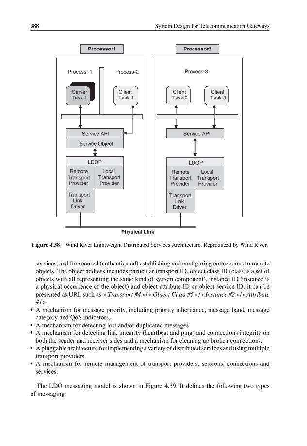
P1: OTA/XYZ P2: ABCc04 BLBK307-Bachmutsky September 2, 2010 13:18 Printer Name: Yet to Come
388 System Design for Telecommunication Gateways
Processor1 Processor2
Process -1 Process-2 Process-3
ServerTask 1
ClientTask 1
Client Task 2
Client Task 3
LDOP
RemoteTransport Provider
LocalTransportProvider
TransportLink
Driver
Physical Link
Service Object
Service API
LDOP
RemoteTransportProvider
Transport Link
Driver
LocalTransportProvider
Service API
Figure 4.38 Wind River Lightweight Distributed Services Architecture. Reproduced by Wind River.
services, and for secured (authenticated) establishing and configuring connections to remoteobjects. The object address includes particular transport ID, object class ID (class is a set ofobjects with all representing the same kind of system component), instance ID (instance isa physical occurrence of the object) and object attribute ID or object service ID; it can bepresented as URI, such as <Transport #4>/<Object Class #5>/<Instance #2>/<Attribute#1>.
� A mechanism for message priority, including priority inheritance, message band, messagecategory and QoS indicators.
� A mechanism for detecting lost and/or duplicated messages.� A mechanism for detecting link integrity (heartbeat and ping) and connections integrity on
both the sender and receiver sides and a mechanism for cleaning up broken connections.� A pluggable architecture for implementing a variety of distributed services and using multiple
transport providers.� A mechanism for remote management of transport providers, sessions, connections and
services.
The LDO messaging model is shown in Figure 4.39. It defines the following two typesof messaging:
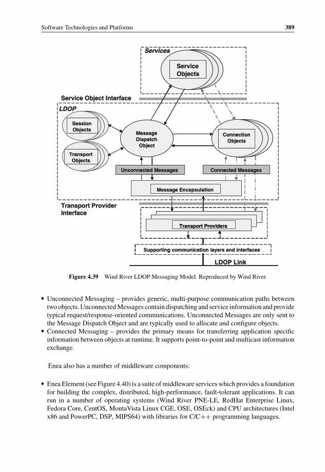
P1: OTA/XYZ P2: ABCc04 BLBK307-Bachmutsky September 2, 2010 13:18 Printer Name: Yet to Come
Software Technologies and Platforms 389
Services
Service Objects
LDOP Link
Transport Providers
Unconnected Messages Connected Messages
Message Encapsulation
Message Dispatch
Object
Connection Objects
LDOP
Transport Objects
Session Objects
Service Object Interface
Transport Provider Interface
Supporting communication layers and interfaces
Services
Service Objects
LDOP Link
Transport ProvidersTransport Providers
Unconnected Messages Connected Messages
Message Encapsulation
Message Dispatch
Object
Connection Objects
LDOP
Transport Objects
Session Objects
Service Object Interface
Transport Provider Interface
Supporting communication layers and interfaces
Figure 4.39 Wind River LDOP Messaging Model. Reproduced by Wind River.
� Unconnected Messaging – provides generic, multi-purpose communication paths betweentwo objects. Unconnected Messages contain dispatching and service information and providetypical request/response-oriented communications. Unconnected Messages are only sent tothe Message Dispatch Object and are typically used to allocate and configure objects.
� Connected Messaging – provides the primary means for transferring application specificinformation between objects at runtime. It supports point-to-point and multicast informationexchange.
Enea also has a number of middleware components:
� Enea Element (see Figure 4.40) is a suite of middleware services which provides a foundationfor building the complex, distributed, high-performance, fault-tolerant applications. It canrun in a number of operating systems (Wind River PNE-LE, RedHat Enterprise Linux,Fedora Core, CentOS, MontaVista Linux CGE, OSE, OSEck) and CPU architectures (Intelx86 and PowerPC, DSP, MIPS64) with libraries for C/C++ programming languages.
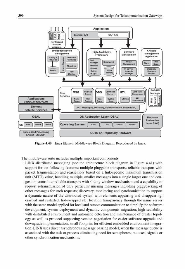
P1: OTA/XYZ P2: ABCc04 BLBK307-Bachmutsky September 2, 2010 13:18 Printer Name: Yet to Come
390 System Design for Telecommunication Gateways
Element API SAF-AIS
Application
SN
MP
CL
I
WE
B
…
Northbound Protocol Adapters
& ConfigProvision
Real-time Statistics
Threshold
PerfMonitor
Ala
rm M
anag
er
Persist
Embedded Device Management
Checkpoint
Fault History
Fault Manager
• Monitor• Detect• Policy• Notify
High Availability Framework
Image Management
In-service Upgrade Manager
Discovery, Resource Monitor
Software Management
AlarmHot
Swap
Chassis Management Application
SN
MP
IPM
I
Cu
sto
m
SAF-HPI Manager
System Log
Utilities API Constructor
Flow Control
Name Server
Command Server
MsgTrace
Linux
Pub/Sub Events
UTILDBGMSG Data Type ConversionCore
Services
Messaging, Discovery, Synchronization, Supervision, …LINX-
OS Abstraction Layer (OSAL)
OSE OSEck OthersOperating System
COTS or Proprietary Hardware
Hardware Abstraction Layer (HAL)
Element ServicesSatelite
ApplicationsCoDEC, IP fwd, VLAN
OSAL
OSE OSEck NPOSOS
Specialized Processing Engine (DSP, NP)
Figure 4.40 Enea Element Middleware Block Diagram. Reproduced by Enea.
The middleware suite includes multiple important components:– LINX distributed messaging (see the architecture block diagram in Figure 4.41) with
support for the following features: multiple pluggable transports; reliable transport withpacket fragmentation and reassembly based on a link-specific maximum transmissionunit (MTU) value, bundling multiple smaller messages into a single larger one and con-gestion control; unreliable transport with sliding window mechanism and a capability torequest retransmission of only particular missing messages including piggybacking ofother messages for such requests; discovery, monitoring and synchronization to supporta dynamic nature of the distributed system with elements appearing and disappearing,crashed and restarted, hot-swapped etc; location transparency through the name serverwith the same model applied for local and remote communication to simplify the softwaredevelopment, system deployment and dynamic components migration; high scalabilitywith distributed environment and automatic detection and maintenance of cluster topol-ogy as well as protocol supporting version negotiation for easier software upgrade anddowngrade implementation; small footprint for efficient embedded environment integra-tion. LINX uses direct asynchronous message passing model, when the message queue isassociated with the task or process eliminating need for semaphores, mutexes, signals orother synchronization mechanisms.

P1: OTA/XYZ P2: ABCc04 BLBK307-Bachmutsky September 2, 2010 13:18 Printer Name: Yet to Come
Software Technologies and Platforms 391
Application Flow Control LINX Client ApplicationPayload Byte Order
Conversion
Management InterfacesTraffic Interfaces
Connection ManagementNaming Service
LinkManagement
Address Resolution
Address Publication
SubscriptionSupervisionSupervision
LINX Transport Protocol
Fragmentation Fragmentation
Bundling Bundling
Sequence/Retransmission
System Byte Order Conversion
Encryption
API Layer
Session Layer
Transport(s) Layer
LinkLayer
Unreliable Interconnects or Protocols
SCTP UDP
Ethernet
Reliable Interconnects or Protocols
SCTP TCP RIO
Shared Memory/PCI
Figure 4.41 Enea LINX Architecture. Reproduced by Enea.
In the LINX model, every module, or communicator, and every link gets its uniquename and the name of the remote communicator is based on the source routing prin-ciples, including all intermediate links. If there are multiple paths to reach the module,multiple addresses can be configured or discovered. Links between nodes can be estab-lished automatically, via a link establishment negotiation protocol with support for healthmanagement, version and endianness negotiation, or manually. The latter method is usedwhen some links usage is not desired, or a specific link priority has to be in place.
To enable the dynamic nature of the distributed system, LINX allows for a module tosubscribe for the destination being available for communication. When the system findsthe destination module anywhere in the system, the subscriber is notified together with apublished remote node address and the first local link(s) to be used for the communica-tion. Any connection can be terminated either by an application or by the LINX when,for instance, the destination module is failed. Also, every module maintains only con-nections that are needed, not all connections to all other nodes; this model allows highersystem scalability with a large number of modules, nodes and links, and simplifies faultmanagement and system reconfiguration tasks.
Sending messages involves only specifying the message pointer and the destination,and the zero-copy shared memory approach is used when available between local nodesor when external links support memory mapping interface. The receiver has more optionsand can choose to receive only certain message types for a priority-based implementation.

P1: OTA/XYZ P2: ABCc04 BLBK307-Bachmutsky September 2, 2010 13:18 Printer Name: Yet to Come
392 System Design for Telecommunication Gateways
LINX for Linux is open source, licensed with a dual GNU General Public License(GPL)/BSD license; some of the implementation of the LINX part in the Linux kernel,such as transport protocols, uses GPL code, but user modules do not fall under GPLrestrictions, because APIs and user space libraries are linked with user modules and carrya modified BSD license. Applications in Linux may use either the native LINX API, orsocket interface to access the communication services.
OSE implementation of LINX is licensed under dual commercial/BSD licensing. TheOSE kernels have performance and scalability adaptations for LINX requiring a separatelicense mechanism.
In April 2009, LINX announced future support for Cavium Networks OCTEON IIprocessors coming onto the market. The reason for this special announcement is becauseOCTEON processors include special hardware mechanisms (memory management, buffermanagement, queue management, traffic management, timers, etc.), which can be utilizedby the middleware for efficient communication schemes.
LINX messaging is often compared to TIPC, because both are targeting the distributedcluster environment with transparent location-independent communication, and based onENEA benchmarks54 LINX has about 10%–25% better performance numbers than TIPC.There is no independent performance comparison publicly available, but even the abovecomparison was measured on Intel Pentium processor. If more special CPUs are used,such as Cavium Networks OCTEON series, performance will depend on the level ofhardware features integration into the specific protocol implementations, and thus mayvary significantly.
– LINX Event Notification Service with one-to-many communication using previouslydescribed publish-subscriber model. As with other LINX services, events are locationtransparent, meaning that producers and consumers can reside on a single CPU, blade, orbe distributed throughout a multi-chassis system.
– Application level flow control service which enables event subscribers to notify the eventproducers about the receivers overflow conditions and the need to throttle messages sentto these applications.
– Logging service which is implemented through Local Log Servers, including supportfor dynamic input filters to control the amount of information that reaches the log, andaggregation into a Global Log Service, which can be archived to the internal or externalpersistent storage. A very useful additional utility is the log browser that allows sortingthe event log using a variety of fields (i.e., application, event ID, time, severity, slot, type,etc) and regular Web browser as a user interface.
A related service is the Command Server. The name is potentially misleading, butit allows applications to publish events with extensive data, including statistics, stateinformation, tables and internal databases. All the data can be viewed using the Webbrowser or CLI.
– Object API, which enables encapsulating groups of smaller components into larger entitiesfor easier software development, deployment, upgrade and management.
– High Availability Framework, which is a full implementation of SA Forum AvailabilityManagement Framework, including fault monitoring, detection, recovery and reportingservices, software lifecycle, release and upgrade management, support for various redun-dancy models with different failover policies, state replication/checkpointing and others.
54 http://www.enea.com/EPiBrowser/Literature%20(pdf)/LINX/LINX%20Benchmarks.pdf.

P1: OTA/XYZ P2: ABCc04 BLBK307-Bachmutsky September 2, 2010 13:18 Printer Name: Yet to Come
Software Technologies and Platforms 393
App A Data
Middleware
OS
Firmware
Pro
toco
l
Node 1
App A Data
Middleware
OS
Firmware
Pro
toco
l
Node 2
App A Data
Middleware
OS
Firmware
Pro
toco
lNode 2
App A Data
Middleware
OS
Firmware Pro
toco
l
Node 1
App A Data
Middleware
OS
Firmware Pro
toco
l
Node 2
App A Data
Middleware
OS
Firmware Pro
toco
l
Node 1
App A Data
Middleware
OS
Firmware Pro
toco
l
Node 2
App A Data
Middleware
OS
Firmware Pro
toco
l
Node 1
User Service
V 1.0 V 2.0
Checkpointing
Checkpointing
Figure 4.42 Enea in-service upgrade sequence example. Reproduced by Enea.
The framework enables in-service software upgrades that analyse the running and newsoftware versions, finds affected modules and upgrades them in a required order definedby a sequence file with standby modules upgraded first and then switching running activemodules with newly upgraded ones (see Figure 4.42 describing four basic steps: pre-upgrade step, phase 1 trial, phase 2 with live new version and phase 3 with both active andstandby running a new version). The upgrade is controlled by the upgrade manager thatutilizes four user-provided configuration and control files: software packing list, versioncompatibility, sequence and fault policy. For example, a sequence file consists of step-by-step actions and rules required to perform the upgrade, including the following: getupgrade sequence, check component upgrade readiness, get upgrade image, check version

P1: OTA/XYZ P2: ABCc04 BLBK307-Bachmutsky September 2, 2010 13:18 Printer Name: Yet to Come
394 System Design for Telecommunication Gateways
compatibility, prepare for upgrade (notify interested application that they are about to beupgraded), set upgrade timeout limits, stop application component, load new versioncomponents, start new version components, on fault behavior.
– Chassis Management service which leverages the SA Forum Hardware Platform Interfaceto access chassis and blades parameters, configuration and statistics. The service discovershardware components and builds the hardware inventory while managing hot-swaptransactions. It also works with the alarm service to publish and aggregate alarms at thechassis level.
– Management protocols and interfaces to enable element and network management tasks.The implementation integrates the ConfD management suite from Tail-F Systems withCLI, Web, SNMP and NETCONF capabilities.
– Integration of dSPEED, DSP farms management platform, which enables extension ofmessaging services, high availability, software management, and chassis managementservices to DSP components. It includes functions such as boot and reset management,inter-process communication, error detection and handling (processor, kernel and usererrors; failed DSP cores isolation and putting the DSP in a controlled state), supervision(link-level supervision, detection of overloaded DSPs and DSP crashes, DSP watchdog),events generation, logging, remote command invocation on DSP processor, statisticsgathering, tracing and debugging, including core dump, host file system access, CLIcommands, and many others.
� Polyhedra in-memory real-time relational database.The Polyhedra database is designed specifically for the embedded world with highmicrosecond-level performance and a small footprint, with support for x86, PowerPC,MIPS and Sparc processor architectures and multiple operating systems, including OSE,VxWorks, Linux, Solaris, AIX, IRIX and Windows. In OSE environment the database isusing OSE Signals messaging mechanism, which is more efficient than a standard TCP-basedcommunication used in other OSs. It can be fully distributed and can run in a redundant con-figuration (see Figure 4.43), when all data modifications to the active database, the master,are replicated to the standby. In the event of the failover, the user applications automaticallyand seamlessly start accessing the standby copy. An additional journaling mechanism pro-tects against the power outages with critical data surviving across the restart of the system.In the distributed system accessing the remote database can be costly from the latency andperformance point of view. Also, in some systems the database query rate can becometoo high in certain circumstances. To minimize the impact in such systems, the Polyhedrasupports configuration of the replica databases, allowing the off-loading of remote queriesor high query rates to local or distributed processors or blades.
The Polyhedra supports data change notifications, called Active Queries, enabling appli-cations to subscribe to data modification events. The subscriber would get the initial datacontent and then only the incremental changes as soon as such change occurs without anyadditional database polling.
The client APIs include native C/C++ libraries with callback model, standard ODBCfunction call set with extensions for active queries, Java JDBC driver, and OLE/DB providerfor languages like Visual C++ and Visual Basic.
Another commercial messaging package comes from Polycore Software. It focuses on mul-ticore multi-chip and multi-blade distributed communication with static interconnect topologyand includes three main components:

P1: OTA/XYZ P2: ABCc04 BLBK307-Bachmutsky September 2, 2010 13:18 Printer Name: Yet to Come
Software Technologies and Platforms 395
User Application
API
User Application
API
User Application
API
User Application
API
Arbiter Arbiter
PolyhedraDatabase
(Master mode)
PolyhedraDatabase
(Standby mode)
Load File Load File
Machine 2 (Standby)Machine 1 (Master)
Figure 4.43 Enea Polyhedra in-memory database in a redundant configuration. Reproduced by Enea.
� Poly-Mapper, which is a GUI Eclipse-based tool with graphical and textual interface forcreation, configuration and reconfiguration a communication topology layout, includingallocated resources. The software includes topology creation wizards, drag and drop ac-cess to change the topology, nodes and links addition and their properties description. Allthat enables the relatively easy definition of static topologies in multicore multi-chip en-vironment. The result of Poly-Mapper is an XML-based communication topology, calledTopology-Map.
� Poly-Generator, which validates the Topology-Map, calculates the shortest path betweennodes, and generates a C-based topology definition, which is further compiled into thetopology object.
� The Poly-Messenger Inter-Processor Communication Framework is a library written inANSI-C and linked with the target application. The application is responsible for serviceplugins that use Poly-Messenger APIs to isolate the messaging infrastructure. Poly-Messenger uses MCAPI specification as a base for its communication APIs. Messagesare sent to different system-wide repositories. If the destination repository is on the localnode, the required action is executed immediately to achieve higher performance; otherwise,the corresponding dispatcher is called to find the best path to the destination, which willcall the driver manager to start data transfer over the mapped physical link(s), being sharedmemory, Ethernet, RapidIO connectivity, or others.
GoAhead Software offers two middleware packages, SelfReliant Advanced Suite and SAF-fire. SelfReliant is a full suite of standards based, hardware- and OS-independent highavailability middleware that manages up to sixty-four nodes. It can be pre-integrated witha number of the third party products, such as RadiSys Promentum ATCA platform, IBMBladeCenter, Performance Technologies’ Advanced Managed Platforms and Oracle TimesTenIn-Memory Database.

P1: OTA/XYZ P2: ABCc04 BLBK307-Bachmutsky September 2, 2010 13:18 Printer Name: Yet to Come
396 System Design for Telecommunication Gateways
SelfReliant®
HARDWARE PLATFORM
OPERATING SYSTEM
Kernel
System Model
Systems Management
Services
High Availability
Services
Messaging Services
Customer-created
Services
CUSTOMER APPLICATIONS
Figure 4.44 GoAhead Software SelfReliant Advanced Suite. Reproduced by permission of GoAhead.
SelfReliant (see Figure 4.44) provides the following services with a run time footprint of5 MB:
� Kernel services with multi-threading support that enables loading and unloading ofSelfReliant and application-specific modules. Its role is to help achieving OS and hard-ware independence. The list of currently supported hardware architectures includes IA(x86), PowerPC and SPARC. From OS point of view, a number of Linux distributionsare supported (RedHat, MontaVista, Debian), as well as Microsoft Windows, Solaris andVxWorks.
� Distributed Messaging Service that provides intra- and inter-node one-to-one, publish-subscribe and server pooling high-performance (up to 40 K messages/sec for point-to-pointand 18 K messages/sec for publish-subscribe communications) communication capabilities.It includes event, fault and error notifications and enables remote procedure calls.
� System model and Availability Management Service enable management of up to 10 Kobjects with their health, operative, administrative and role states. The system model canbe replicated to the hot standby availability management sub-system. It supports multipleredundancy models: 2N, N+1, N+M, active/active, and even custom. Any active resource(applications and operating systems, middleware packages, chassis and blades, CPUs andI/O devices and others), can have a virtual IP address and redundancy role dynamically as-signed. In addition, SelfReliance offers Simplified Availability Management allowing start,stop, restart and fast switchover for pairs of applications and/or nodes in active-standbyand active-active configurations. Modified applications can failover in 10 msec, unmodi-fied applications (see also Transparent Application Management Service) can failover in300 msec.

P1: OTA/XYZ P2: ABCc04 BLBK307-Bachmutsky September 2, 2010 13:18 Printer Name: Yet to Come
Software Technologies and Platforms 397
� Cluster Management Service manages the physical nodes or instances of SelfReliant andmonitoring the health and status of every node in the cluster. It supports redundant networkinterfaces and multiple network topologies.
� Replicated Database Service provides database replication with a capability to throttle thereplication rate.
� Platform Resource Management Service provides SA Forum HPI compliant hardware re-source management capabilities.
� Transparent Application Management Service enables high availability for applications thatdo not require modification or are impossible to modify, but can be used with modifiedapplications to provide application startup, monitoring, shutdown, etc. The service supportsvirtual IP address switchover.
� Integrated Platform Services with hot swap management, alarm management, and storagemanagement included.
� Systems Management Services with the components such as Management Console for abrowser-based cluster management, SNMP agent (standalone and master/subagent imple-mentations) and MIB compiler, SNMP object MIB module to access the system model usingSNMP protocol, HPI MIB module for hardware resources management using SNMP proto-col, embedded Web server with 60 KB footprint and sixty-five connections per second forHTML remote access, control and status/alert display, and management in-memory databasefor system services only (not for application use) with a small footprint and optimized readaccess time of less than 3 µsec and write access time of less than 19 µsec for 64B data.
� Custom services that can be created by users to enhance the existing middleware function-alities.
GoAhead SAFfire middleware includes all SelfReliant functions and also implements SAForum ASI specification, including Availability Management Framework, Information ModelManagement, Cluster Membership Service, Checkpoint Service, Event Service, Message Ser-vice, Notification Service, Log Service, Timer Service and Platform Management Service (seeFigure 4.45).
Continuous Computing integrates fully GoAhead SAFfire middleware, but it goes muchfurther in its offerings by adding Middleware Tool Kit to support integration of protocolswith SAFfire, Trillium Essential Services & management tools (including ES-CONFIG &ES-EMS platform configuration & commissioning Graphic User Interface; System diagnos-tics & remote console access, firmware upgrades, etc; and L2HA switch and link monitoring& fault management application), and Trillium fault-tolerant protocol stacks covering fieldsof Long Term Evolution (LTE) and 3G networking, Femtocells, IP Multimedia Subsystems(IMS), Voice over IP (VoIP), SS7, SIGTRAN, broadband, load distribution and high availabil-ity. For example, the Distributed Fault-Tolerant/High-Availability (DFT/HA) core softwarefunctionality (see Figure 4.46) enables creation of distributed fault-tolerant applications bysupporting multiple system configurations, automatic system initialization, protocol layer spe-cific configuration, different load distribution criteria between active application instances,complete recovery during failure by copying stable states to the standby, application restart onprocessor loss, support of multiple processor failures, graceful node termination, in-servicesoftware upgrade, alarms for failure detection and statistics for more efficient load distributionand troubleshooting.

P1: OTA/XYZ P2: ABCc04 BLBK307-Bachmutsky September 2, 2010 13:18 Printer Name: Yet to Come
398 System Design for Telecommunication Gateways
Information Model Mgmt
Notification
Log
MIB Tools
Alarm Management
SNMP Agent
Cluster Membership
Checkpoint
Event
Message
Timer
Management Database
Resource Virtual IP
ApplicationsS
yste
ms
Man
agem
ent
Ser
vice
s
Ap
plic
atio
n S
ervi
ces
Platform Management
Service
Availability Management Framework
Pla
tfo
rm M
anag
emen
t S
ervi
ces
Ava
ilab
ility
Man
agem
ent
Ser
vice
s
Cluster Management
Distributed Messaging
Action EJ Console Webs Base
Foundation Services
Kernel
Hardware Platform Running Standard Operating System
Open Standards-Based Availability and Management MiddlewareSAFfite™GoAhead®
Figure 4.45 GoAhead Software SAFfire middleware. Reproduced by permission of GoAhead.
Upper LayerUpper Layer
Lower LayerLower Layer
Load Distribution Function
Load Distribution Function
Load Distribution Function
Load Distribution Function
Copy 1 (Active/Standby)
Copy 2 (Active/Standby)
Copy 3 (Active/Standby)
Copy n (Active/Standby)
Distributed Protocol Layers
Figure 4.46 Continuous Computing Distributed Fault-Tolerant/High-Availability architecture. Repro-duced by permission of CCPU.

P1: OTA/XYZ P2: ABCc04 BLBK307-Bachmutsky September 2, 2010 13:18 Printer Name: Yet to Come
Software Technologies and Platforms 399
Customer Applications
Distributed Event Manager
Clovis IMM RegistryObject Management
Buffer Management
Rule-base Engine
HSM LibraryInfrastructure Core
Remote Method Dispatch (RMD)
Intelligent Object Communication (IOC)
OS Abstraction Layer (OSAL) Transport Object (TO) HW Abstraction Layer (HAL)SA Forum HPIIPMITransports of Choice
Linux, Solaris, VxWorks, QNX Device Driver
Hardware Platform
SA Forum AIS Clovis APIs
Res
ou
rce
Mg
r
Ava
ilab
ility
Ala
rm M
gr
Fau
lt M
gr
Med
iati
on
Mg
r
Po
licy
Mg
r
Ch
eckp
oin
tin
g
Hit
less
Up
gra
de
Ch
assi
s M
gr
Dia
gn
ost
ics
Mg
r
Per
form
ance
Mg
r
Lo
gg
ing
Pro
visi
on
En
gin
e
Pro
file
& D
ebu
g
Co
mp
on
ent
Mg
r
Figure 4.47 OpenClovis Application Service Platform Architecture. Reproduced by permission ofOpenClovis.
All protocols are implemented using the same Trillium Advanced Portability Architecture(TAPA
R©), a set of common architectural and coding standards that defines four interfaces:
upper and lower layers through Service Access Points (bind/unbind, connect/disconnect, datatransfer, reset and flow control functions; inter-layer communication can be achieved usingeither direct function calls for tightly coupled modules or using inter-process communicationfor loosely-coupled modules residing in different processes or even on different processorsor blades), layer management (runtime configuration, control, statistics, status, alarm andaccounting functions) and system services (the initialization, timer management, messagemanagement and queue management functions).
Also, Continuous Computing’s Trillium products are implemented with a multicore and/orhardware multithreaded environment in mind, taking full advantage of many multicore prod-ucts from Cavium Networks, Sun, NetLogic and others.
Another good middleware solution is the OpenClovis Application Service Platform thatincludes most of the components required in telecommunication products (see Figure 4.47).
It uses SA Forum HPI for hardware integration and has the following modules:
� OS and hardware abstraction layers that are targeted to make the rest of the middleware OSand hardware independent.

P1: OTA/XYZ P2: ABCc04 BLBK307-Bachmutsky September 2, 2010 13:18 Printer Name: Yet to Come
400 System Design for Telecommunication Gateways
� Transport Object that provides interface to communication links and protocols stacks. It canuse TIPC or UDP/IP or can be mapped directly into Layer 2 protocols running over ATM,Ethernet, RapidIO links and others.
� Intelligent Object Communication that provides location-transparent messaging servicesbetween the middleware objects distributed throughout the system.
� Remote Method Dispatch that invokes various software modules transparently, regardlessof their location.
� Distributed Event Manager that serves the middleware modules, as well as user applications.� Infrastructure Core that serves the middleware modules with object management,
rule-based engine, state machine management library and object registry, which is an object-oriented database enabling one to manage objects and the relationships between them, objectlife-cycle, transactions on multiple objects, object change notifications and object changepropagation.
� Services, including core SA Forum services such as AMF redundancy manager, check-point manager, cluster/group manager, messaging service, event manager, name service, logmanager as well as SA Forum value-add extensions services like provisioning manager,alarm manager, fault manager, component manager, chassis manager, transaction manager,in-service software update and management mediation service.
� Besides ASP middleware, OpenClovis also provides a suite of tools to help accelerateapplication design, development, integration and testing.
Applications can access all services through standard compliant SA Forum APIs and Open-Clovis proprietary extensions.
There are a number of open source and commercial in-memory databases, besides theabovementioned Polyhedra. Probably, the two most popular are IBM SolidDB and OracleTimesTen.
SolidDB is a relational database that includes both IMDB and a traditional database,both accessed through the same SQL interface (ODBC and JDBC interfaces are also avail-able). There is also an open source version of SolidDB for MySQL. SolidDB is offeredeither as a standalone IMDB or a cache solution for any other relational database runningon Linux, Solaris or Windows. In both cases it has a high availability and instant failoverfrom active instance to standby in a hot-standby configuration. One advantage of SolidDBis that it has already been deployed in many telecommunication products from multiplevendors.
Oracle’s TimesTen has many capablilities that are similar to SolidDB, including interfaces.Its Cache product caches the frequently used data of the regular Oracle Database EnterpriseEdition in an IMDB portion. Its DataServer product is a pure IMDB optimized for memory-based structures, with non-blocking operations, integrated event notification services andreplication functionality for highly available implementations. One factor to be aware of isthat the TimesTen is priced per processor as per the Oracle online shopping site,55 whichcreates many problems for multicore, multichip and multiblade configurations, assuming thatthe functionality can move between different domains making it not only expensive, butpractically impossible to predict how many processors are indeed using the database services.
55 https://shop.oracle.com/pls/ostore/product?p1=oracletimesteninmemorydatabase&sc=ocom_oracletimes-teninmemorydatabase.
P1: OTA/XYZ P2: ABCc04 BLBK307-Bachmutsky September 2, 2010 13:18 Printer Name: Yet to Come
Software Technologies and Platforms 401
Also, many operators do not allow collecting processor usage information and providing it tothe suppliers, making run-time flexibility highly complex for such processor-oriented charging.This is not a technical issue, and this book usually avoids any product business models, butproblems with the most advanced systems must be considered and potentially negotiated withOracle.
A number of other high-performance IMDBs are the following:
� Altibase,56 which has both in-memory and storage-based databases selectable on a per-tablebasis. It has SQL precompiler and ODBC/JDBC interfaces and supports replication betweentwo data bases for high availability purposes. The database is popular in South Korea and insome telecommunication systems in China.
� Open source relational fault-tolerant IMDB BlackRay57 developed by Deutsche Telecom fora particular project. It supports SQL, text search in text fields, wildcards and index functions,low latency search, object oriented API (Java and C++), fully separated multiple instancesrunning concurrently as separate processes with every instance defining its own schemas andtables, snapshots to the disk for persistency and recovery (in the case of failure the recoverycan be done only from the latest snapshot) and more. It is dual licensed either under GPLv2or proprietary license.
� Open source relational IMDB CSQL,58 which also has a regular database caching modeand replication capability for high availability or load balancing. Based on testimonials, thedatabase is fast and well-fit for real-time applications with customers like Wipro Technolo-gies and Nokia Siemens Networks (based on public announcements, the former uses it forIVR application, the latter for existing Oracle database caching).
� Raima Database Manager Embedded ACID-compliant library combines in-memory, disk-based and hybrid modes. It is used in millions of embedded and real-time systems in avionics,military, telecommunication and other applications, including routers, switches and mobilenetworks base stations from vendors like Cisco Systems, Juniper, Nortel, Alcatel-Lucent,3COM and others. It can have multiple threads accessing a single database, and has a numberof APIs available: C, Java, XML, mirroring for high availability and a single master multipleslaves replication.
� eXtremeDB59 is an ACID-compliant embedded in-memory and disk-based database fromMcObject designed for real-time applications. It is used in military, aerospace, industrial andtelecommunication systems, including routers, switches, and mobile network base stationsfrom vendors like SOMA Networks, F5 Networks, and many others. It has a small footprintand a low latency and it can be accessed through SQL, XML and native C/C++ APIs. Itincludes high availability edition to maintain hot-standby configurations. It can run on manyoperating systems, such as Linux, QNX, VxWorks, LynxOS, Nucleus, Solaris, and more.One potentially valuable feature is the capability to access the database directly from thekernel, which can save unnecessary context switches between user and kernel modes.
56 http://www.altibase.com/english/.57 http://www.blackray.org/.58 http://www.csqldb.com/.59 http://www.mcobject.com/extremedbfamily.shtml.

P1: OTA/XYZ P2: ABCc04 BLBK307-Bachmutsky September 2, 2010 13:18 Printer Name: Yet to Come
402 System Design for Telecommunication Gateways
4.2.2 Management Plane
Management plane software is involved during the factory configuration, initial deploymentin the field and constant maintenance while in service, including configuration, softwareand hardware addition/removal/upgrade/downgrade, monitoring, statistics collection, eventcollection, license upgrade/downgrade and many other tasks.
The complexity of management plane implementation is often underestimated during theproject planning phase. Based on experience with multiple projects, it is not rare that themanagement plane development effort can take up to 50% of the entire project, depending onthe level of software reuse or software platform readiness.
In a system with a single OS the management plane is usually a separate process. In asystem with integrated virtualization it would most probably be running in a separate virtualmachine. In many systems, especially in a multicore and/or multichip scenario, there are twooperating systems or OS instances, one for data plane and another used by both control andmanagement planes.
The management plane is usually activated by three main sources:
� Message is received from the external interface. It can be either debug port, or externalserial interface for terminal-like access, or external network interface dedicated for themanagement plane use representing only out-of-band management, or external networkinterface shared with the rest of the traffic and redirected to the management plane byhardware-implemented classification rules.
� Message or event received from data or control plane. Many telecommunication systemsare implementing an architecture where all external packets are received by the user plane,classified in the software as a management packet and passed to the management planeprocessing via some internal interface, which can be internal physical port, internal logicalport, such as VLAN, shared memory, communication with data or control plane througha hypervisor or another microkernel, or hardware-based message passing using hardware-managed buffers and queues. For example, PING messages for system health determinationcan be processed by the management plane, but it is often used for measuring the data planeround trip time, and in such scenario is processed by the data plane instead.
It can also be an internal message originating in the data or control plane applications,including collection statistics, failures and other events to be stored and/or reported to theproduct and network management layers, responses for previous management requests andothers. It is possible to receive events directly from the hypervisor if one is included inthe system and these events can notify about other virtual machine status changes, or someimportant system changes being monitored by the hypervisor, or a hypervisor decision toschedule the management plane for any reason.
� Internal events are generated, including timers, interrupts indicating an operation termination(disk, DMA, hardware offload engine, etc.) or management ports status changes, and more.
The management plane is not considered a real-time component and as such is implementedon a general purpose operating system, such as Linux or Solaris; however, in some systems itcan run as a process of an RTOS, when multiple OSs running simultaneously are undesirablefor any reason. Management plane requirements come more from the APIs and functionalityrichness as opposed to the performance, throughput or latency characteristics of the system.

P1: OTA/XYZ P2: ABCc04 BLBK307-Bachmutsky September 2, 2010 13:18 Printer Name: Yet to Come
Software Technologies and Platforms 403
This chapter includes a description of some management plane specific blocks not discussedpreviously in Sections 4.1 and 4.2.1.
4.2.2.1 Command Line Interface
A command-line interface (CLI) is a text-only representation of commands (as opposed tographic user interface, or GUI, rarely available in telecommunication products directly withouta special management station) targeted at management communication with a software moduleor subsystem. CLI is one of the most popular management mechanisms for system and networkadministrators and is accessible through Telnet, Secure Shell (SSH) or console.
CLI syntax and semantics are normally proprietary, but there are some de-facto ‘standard’styles in telecommunication, specifically one from Cisco Systems and another from Juniper.The products of these two vendors are widely used in many networks throughout the world;therefore, system and network administrators know them well and prefer or even expect similarlogic from other vendors as well.
Independently on the syntax, some CLI command interpreters accept only the whole lineand start interpretation after the input has finished by pressing the ‘Enter’ key, but the moreadvanced will try to analyse commands character-by-character while they are being typedenabling earlier filtering of commands based on access rights, earlier error indication andsmart keywords completion specific to a particular context, including automatic addition ofkeywords if there is only a single option available, a capability to accept only the beginningof the word if it can be completed only in a unique way and a capability of truncating thecommand after it becomes unique; many engines use the ‘Tab’ key as a request to togglebetween multiple options. The CLI engine can include built-in scripting capabilities so asto be able to execute a batch of commands by issuing only a single command. They canimplement a command repetition mechanism, such as executing a command multiple timesand/or for a number of contexts or automatic repeating of the command for multiple interfaces.The command syntax may enable optional parameters/keywords with or without the defaultvalue, which will be added automatically if not provided explicitly.
CLI commands can be viewed as a hierarchical structure, or tree. Sometimes any commandof any level can be accessed from any location; other implementations allow only a subsetof commands to be accessible at any level and there are strict implementations that allow aparticular hierarchy to access only commands specific to that location in the command tree.To help in the location identification and current configuration mode, the CLI engine usuallyprints the path from the root to the location as a command prompt, similar to the directorypass presented by DOS CLI or website tree Uniform Resource Locator (URL).
In many projects, at least a partial CLI is one of the first tools built into the system toenable quick configuration, status presentation and debug of other software modules still inthe development process. While some debugging commands exist only at the developmentstage, others could be present even in the final product and enabled with a particular privilegelevel or a password-protected configuration mode.
Complex telecommunication systems include multiple operating systems or multiple in-stances of the same operating system located on different cores, processors, blades or chassis.One way to manage such systems is to enable independent CLI access to every such com-ponent, but this architecture would not scale well. A more prevalent implementation is when
P1: OTA/XYZ P2: ABCc04 BLBK307-Bachmutsky September 2, 2010 13:18 Printer Name: Yet to Come
404 System Design for Telecommunication Gateways
only a single CLI session is needed to be able to manage all components by having a masterCLI interpreter becoming a proxy to other interpreters or CLI backend modules (responsiblefor performing actions required by the command) and moving commands and responses be-tween the master and slave instances. The CLI proxy can be used in scenarios where a singleCLI command is destined for multiple modules simultaneously, such as a configuration ofthe same parameters for all instances of the application or multiple applications, or when asingle command requires a chain of actions from different modules. In the latter case, theproxy would send a command to one module, receive a response, send another command tothe second module, receive a response, and so on, until the entire processing is done and anaggregated response can be sent to the operator.
An additional complexity arises when one of sub-commands fails and all actions performedby previous steps have to be rolled back to their original state. It can be implemented either bythe CLI proxy, or alternatively all actions are done by the backends temporarily and committedonly when all parts of the command or all commands in the script are completed successfully.In most cases there should be a way to specify negative or rollback commands manually. Oneexample of the syntax is the ‘no’ keyword followed by the command in Cisco CLI. However,sometimes it becomes not very intuitive, as in the case of ‘no shutdown’ command, whichcan mean a ‘turn on’ or ‘enable’ action. Another example of rollback is manual or automaticconfiguration backup and restoring the configuration when a rollback is required.
Most CLI commands are usually logged to be able to review modifications requested bydifferent managers and their results.
4.2.2.2 Simple Network Management Protocol
The Simple Network Management Protocol (SNMP) is a must-have capability in any telecom-munication system, mainly because it is the main interoperable environment integratingmanaging and managed devices from different vendors by means of data description andprotocols using the universal ASN.1 syntax notation. There is a great deal of informationavailable about SNMP, one useful reference is [SNMP-Essential], however IETF RFCs areoften the best available resource. The protocol runs on top of the UDP transport layer (it canalso run on top of TCP and other transport schemes, but is rarely implemented using them)and enables management-related communication between one or more managers, or masters,incorporating the network management system (NMS) software, and one or more manageddevices, or slaves, through the integrated software module called agent. SNMP supports bothpush and pull modes: the master can request the information using GET, GETNEXT andGETBULK primitives and modify device parameters using SET messages; slaves can alsoinitiate the management update procedure using TRAP and INFORM transactions. The SNMParchitecture and the primitives are described well in the IETF RFC1157.60
The protocol itself is indeed very simple and is usually not a development and maintenancebottleneck. The main effort is expended on the NMS, which is outside the scope of this book,the device’s hierarchical tree-based representation of the managed scalar and tabular objects
60 A Simple Network Management Protocol (SNMP): http://www.tools.ietf.org/html/rfc1157.

P1: OTA/XYZ P2: ABCc04 BLBK307-Bachmutsky September 2, 2010 13:18 Printer Name: Yet to Come
Software Technologies and Platforms 405
and their instances (variables) organized into Management Information Bases, or MIBs61 andits manipulation during read and write accesses. Standard MIBs are defined by IETF andIEEE; specification examples (there are more than 300 MIB standard specifications) includeInterface MIB62 , Fibre Channel MIB63 , TCP MIB64 , UDP MIB65 , IP MIB66 and AlarmMIB67 , to mention but a few. There are also vendor-specific MIBs with the total number ofMIBs exceeding 10 000.68 MIB data fields can be defined using standard field types, whichinclude bit and octet strings, signed and unsigned integers, 32-bit and 64-bit counters, networkaddresses (such as IPv4 address), gauges (non-negative integers with configured value ranges),time ticks and even opaque type in order to be able to define arbitrary information not definedby the standard.
SNMP went through three iterations/versions: SNMPv1, SNMPv2 and SNMPv3. SNMPv1defined a basic information structure, data types and operations enabling working on a specificlocation in the table or the entire row. SNMPv2 added a number of data types, such as 64-bitcounters, network addresses and bit strings, operations (for example, GETBULK operationenables extracting large amount of data in a single request), capabilities and complianceparameters and the not very popular security option, which was later removed in a modifiedSNMPv2c version. The security functionality was added later into the SNMPv2u revision.The latest specification, SNMPv3, includes also security (privacy, authentication and accesscontrol) and remote configuration. The security inclusion is a critical component in any networkmanagement procedure making SNMPv3 a mandatory requirement for all newly developedsystems. However, even SNMPv3 can be vulnerable to a number of security issues includingbrute force, dictionary and spoofing attacks, default parameters usage and more.69
Specifications were developed with built-in backwards compatibility allowing SNMPv2agent to translate requests between SNMPv1 agent and SNMPv2 NMS. For instance it canemulate external NMS GETBULK request into as many as needed internal GETNEXT requestsbefore sending a single response back to the management station. Similarly, the SNMPv3 agentcan play the role of SNMPv2 and SNMPv1 proxies.70
SNMP is a mandatory requirement for any managed telecommunication system, but itis definitely not a panacea for all management problems. Using SNMP with large tables,operations on table columns, processing of sparsely populated tables, complex relationshipbetween fields and/or tables and many other use cases is not the ideal environment. This isone of the main reasons why CLI together with proprietary management stations, capable ofperforming operations with a single click of a button and a single message sent to the client,
61 Management Information Base (MIB) for the Simple Network Management Protocol (SNMP): http://www.tools.ietf.org/html/rfc3418.
62 The Interfaces Group MIB: http://www.tools.ietf.org/html/rfc2863.63 Fibre Channel Management MIB: http://www.tools.ietf.org/html/rfc4044.64 Management Information Base for the Transmission Control Protocol (TCP): http://www.tools.ietf.
org/html/rfc4022.65 Management Information Base for the User Datagram Protocol (UDP): http://www.tools.ietf.org/html/rfc4113.66 Management Information Base for the Internet Protocol (IP): http://www.tools.ietf.org/html/rfc4293.67 Alarm Management Information Base (MIB): http://www.tools.ietf.org/html/rfc3877.68 For the extensive searchable MIBs database, refer to http://www.mibdepot.com and http://www.mibsearch.com.69 http://www.cert.org/tech_tips/snmp_faq.html.70 Coexistence between Version 1, Version 2and Version 3 of the Internet-standard Network Management Frame-
work: http://www.tools.ietf.org/html/rfc3584.
P1: OTA/XYZ P2: ABCc04 BLBK307-Bachmutsky September 2, 2010 13:18 Printer Name: Yet to Come
406 System Design for Telecommunication Gateways
are the most popular means of network and device management today. This creates the well-known ‘stickiness’ problem, when it is difficult to replace one vendor with another withoutreplacing the entire management layer, requiring re-training of the administration staff. It alsomakes the management layer one of the most important value-adding propositions for everylarge deployment project.
4.2.2.3 Secure Shell
Secure Shell (SSH) is a TCP-based client-server protocol designed to replace unsecuredcommunication provided by Telnet, rlogin, rsh, rcp and similar remote shell mechanisms;SSH clients are available for all major operating systems. It uses public-key cryptographyfor remote computer authentication and user authentication if needed. Most frequently it isused just for a shell login on a remote host or for executing a single command on such ahost, but it also has a tunneling capability to send unencrypted data over the secured channeland includes secured file transfers via Secure Copy (SCP) and the more robust SSH FileTransfer Protocol (SFTP); the latter includes functionalities to resume previously interruptedfile transfers, directory listing, remote file deletion and other file system operations. Thereare more uses for SSH, including full VPN, remote directory mounting, Internet browsingthrough the secured proxy and others, but these are outside of the scope of the managementplane implementations.
A good description of SSH can be found in [SSH-Guide], while the latest SSH specificationsare defined by a number of IETF RFCs:
� The overall architecture is defined in the IETF RFC4251.71
� Client-driven user authentication layer is defined by the IETF RFC4252,72 including suchmethods as password-based, public key, keyboard-interactive for one-time authenticationwith SecurID and similar schemes, and vendor-independent Generic Security Services Ap-plication Program Interface enabling external mechanisms for a single sign on capabilitywith SSH integration.
� The transport layer is defined by the IETF RFC 425373 and covers initial key exchange andre-exchange based on amount of data transferred or time passed from the last successful keyexchange, server authentication, setting up encryption and integrity verification and API forsecured data sending over the established secured channel.
� The connection layer is specified in the IETF RFC 4254.74 It describes SSH connectionswith one or more bi-directional channels (three types of channels are defined: shell forterminal shell and file transfer needs, direct tcpip for forwarded client-to-server channelsand forwarded tcpip for forwarded server-to-client channels), as well as channel-specificand global requests and their use cases.
� The way to use DNS for secure publishing of key fingerprints is provided by the IETFRFC4255.75
71 The Secure Shell (SSH) Protocol Architecture: http://www.tools.ietf.org/html/rfc4251.72 The Secure Shell (SSH) Authentication Protocol: http://www.tools.ietf.org/html/rfc4252.73 The Secure Shell (SSH) Transport Layer Protocol: http://www.tools.ietf.org/html/rfc4253.74 The Secure Shell (SSH) Connection Protocol: http://www.tools.ietf.org/html/rfc4254.75 Using DNS to Securely Publish Secure Shell (SSH) Key Fingerprints: http://www.tools.ietf.org/html/rfc4255.
P1: OTA/XYZ P2: ABCc04 BLBK307-Bachmutsky September 2, 2010 13:18 Printer Name: Yet to Come
Software Technologies and Platforms 407
4.2.2.4 Web Configuration
In an attempt to make device configuration a simpler process, the familiar Web-based interfacecan be used. Many popular standard Web browsers can be used as clients and the device runsthe Web server. Managers are always authenticated and the entire communication channel can(and is highly recommended to) be secured.
There are a number of advantages for Web-based configuration. First of all, it is based onGUI compared to the text-based CLI with complex syntax rules, meaning that much shortertraining is required for its efficient use and a smaller number of mistakes is made duringconfiguration. It also reduces the stickiness factor described previously, which can be viewedas a positive parameter for the operator and can be either positive or negative element forequipment manufacturers, depending on whether they attempt to continue being deployed orreplace the ‘incumbent’ supplier. Another differentiator, which can be interpreted as positiveor negative depending on the deployment situation, is the shift of value-added managementfrom the centralized management station to the managed device itself.
As with other management tools, Web configuration development involves front-end andback-end components. In general, it is a good guideline to design and develop only a singlecommon back-end software package capable of interface with a number of front-end modulessimultaneously. This design would mean that the major complexity for Web configurationimplementation is the additional effort of its front-end. It has to be clear that this effort can beon one hand quite significant and on the other requires different skills and competencies. Forexample, CLI front-end involves the development, or more probably the integration (see Sec-tion 4.2.2.6), of the command parsers and syntax analysers. Web-based front-end includes Webserver(s), Web page building tools, HTML editors, Java scripts development and Java middle-ware. It raises issues of different Web browsers and their compatibilities, page formatting fordifferent browsers and screen resolutions and more.
There is no doubt that the Web configuration capability adds significant code and effort. Atthe same time, it has a great appeal for potential customers and with that point in mind it hasto be considered seriously as a candidate for management plane development.
4.2.2.5 XML
XML is another excellent mechanism used for the management plane in many telecommuni-cation systems.76 It is sometimes used as a standardized interface between different modules,such as a communication between management front-end and back-end software. In theseimplementations, front-end components translate the commands and other inputs into theXML files and pass this information to the back-end component, which includes XML parserfunctionality and the interpretation of parsed fields. However, XML can be much more thanan internal interface layer based on its rich set of capabilities:
� It has ASCII representation enabling a wide set of tools to be used to create and process XMLfiles. In addition to regular ASCII editors, there are many XML-specific tools, includingXPath for search, XSLT scripts for automatic data transformation, XML-enabled databases,
76 See, for example, Juniper’s whitepaper at http://www.juniper.net/solutions/literature/white_papers/200017.pdf.
P1: OTA/XYZ P2: ABCc04 BLBK307-Bachmutsky September 2, 2010 13:18 Printer Name: Yet to Come
408 System Design for Telecommunication Gateways
file comparison tools and many others. This also means that it is viewed in an easy readableand self-explanatory format well-suited to external interfaces.
� It can handle practically any data structures and data hierarchies and dependencies. At thesame time XML files can be bound by the creation of XML schema definitions, whichenforce a much more concrete structure. XML schemas are created using special languages,such as the Document Type Definition (DTD), XML Schema (W3C), RELAX NG, Schema-tron and Examplotron.77 This two-layer structured view provides much needed flexibilityfor backward and forward compatibility with relatively easy data set modifications andexpansions.
� It can be carried over console, telnet or SSH connection ensuring the required level oftransport layer features and security.
� XML can be used for complex remotely controlled functions. For example, XML-RPC78 isusing XML over HTTP transport to invoke remote procedure calls. It evolved into the evenmore complex Simple Object Access Protocol (SOAP)79 competing with other middlewaretechnologies such as Common Object Request Broker Architecture (CORBA) specified byObject Management Group.80 Describing these advanced implementations is not within thescope of this book, but they are mentioned here in order to emphasize XML’s huge potentialas a base for many other features.
ASCII processing in general and XML parsing in particular are usually slower than com-parable binary encoding schemes. However, in addition to all of the advantages describedabove, it is important to consider two extra factors: management plane performance is usuallyless critical compared to functional richness and many of the latest generation of processorsinclude hardware offload blocks, such as regular expression and XML parsing (see Sections3.5.5 and 3.5.6).
4.2.2.6 Commercial and Open Source Solutions
There are many commercial and open source solutions that can be utilized for efficient systemdesign and development. It is practically impossible to describe all of them, or even themajority of them, without altering the focus of the book. Therefore, only a few examples arementioned or described briefly below.
Wind River’s WindManage CLI architecture is presented in Figure 4.48. The clients connectto the system using a secured shell or telnet session. After establishing a session, clients sendtext-based commands that are parsed by the CLI framework using the command tree databaseand parsing library. After the command is parsed successfully, it is sent to the WindManageBackplane which can execute the command or forward it to external applications.
WindManage CLI includes the following list of features:
� Drop-in, pre-built commands.� Telnet server.
77 See schemas comparison at http://www.xml.com/pub/a/2001/12/12/schemacompare.html.78 http://www.xmlrpc.com/.79 http://www.w3.org/TR/soap12-part1/.80 http://www.omg.org/technology/documents/corba_spec_catalog.htm.

P1: OTA/XYZ P2: ABCc04 BLBK307-Bachmutsky September 2, 2010 13:18 Printer Name: Yet to Come
Software Technologies and Platforms 409
Application 3Application 2Application 1
BackplaneWindManage
CLI Command Tree
Shell Interface
Telnet/SSH Daemon
Packet Interface
SerialInterface
Parsing Engine
Command Tree Database
Client
Figure 4.48 Wind River WindManage CLI Architecture. Reproduced by Wind River.
� Command completion.� Context-sensitive help.� Command history.� Intermediate mode handling.� Parameter handling, verification, and grouping.� Negate commands (e.g. to restore defaults).� Support for simultaneous Telnet sessions and serial ports.� Common command libraries included.� Security parameters defined by object, command, or session.� Fully re-entrant ANSI C code.
The missing potentially useful features (some of which may have been added by the timeof publication) are:
� Supports only scalar objects, support for tables or multi record must be added.� Support for executing commands from a file is required.

P1: OTA/XYZ P2: ABCc04 BLBK307-Bachmutsky September 2, 2010 13:18 Printer Name: Yet to Come
410 System Design for Telecommunication Gateways
� Support of multiple configuration versions, such as current configuration, backup configu-ration and previous configuration.
� Rollback of configuration to previous configuration.� Support for executing standard Linux commands for privileged user is required.� Restricting number of simultaneous connections and number of connection per minute to
prevent denial-of-service attack.� Support for SSH.
The WindManage CLI graphical interface is integrated with Wind River’s Workbench andthe following steps describe briefly the creation of sample commands:
� Create a Wind River’s CLI project file: this step configures project settings such as projectname, path, generated output file names, directory for generated C and header files, etc.
� Using the WindManage GUI, define variables that are used to represent information usedin command line interface. These variables are referred to as windmarks and are used fordefining commands later. Each windmark contains multiple attributes, such as type (string,integer, etc.), range, length, permissions (read, write), handler, and others.
� After creating windmarks, the GUI tool creates a command tree, one node at a time.Each node contains node name, help string, help handle, parameters, handler functions andassociated windmarks.
� Add command handler functions and parameters to command. The handler function is alsoused to associate windmarks.
� Generate the command tree database.� Add access control for selective authorization: command level access control, parameter
level access control, Wind River’s mark level access control. These access rights can befor command or windmarks. In addition, users are associated with levels, so only users ofcertain level can be assigned access permission.
� Implement handler functions and build the CLI application.
There are some open source CLI parsers with different levels of complexity and feature set.These include CodePlex,81 Argtable,82 Apache Commons83 (Apache community is workingon the redesigned CLI2 software as a part of Commons Sandbox project) and others.
Open source implementation of the SSH protocol, OpenSSH,84 is included in most Linuxdistributions. It is feature-rich, actively maintained with two to three releases per year. Supportfor other operating systems and the latest release can be downloaded directly from the mainproject Website.
When the creation and/or processing of XML files is required, Altova XMLSpy can be achoice for XML editor and a development environment for modeling, editing, transformingand debugging XML-related technologies. XMLSpy supports text and graphical views, suchas Grid view, XML Schema view, WSDL view, XBRL view, Authentic view and Browserview, all with a rich set of features, including the following:
81 http://www.codeplex.com/commandline.82 http://www.argtable.sourceforge.net/.83 http://www.commons.apache.org/cli/.84 http://www.openssh.com.
P1: OTA/XYZ P2: ABCc04 BLBK307-Bachmutsky September 2, 2010 13:18 Printer Name: Yet to Come
Software Technologies and Platforms 411
� XML Schema and DTD-based XML validation.� Multi-tabbed validation window for searching over multiple files.� Context-sensitive entry helpers.� Built-in XML document templates.� Conversion utilities.� XML-aware find and replace and Find in Files window.� Intelligent XPath auto-completion.� XSLT / XQuery debuggers and profilers.� Database integration.� XBRL support.� XML-aware file differencing.� Royalty-free program code generation.� Integration with Visual Studio R© and Eclipse.� Java and COM APIs.� Java/C/C++ code generation from XML Schemas.� Very large file support.
When there is no need for the development of complex XML files and schemas are notexpected to change frequently, and thus the code that uses the schemas would not need tobe regenerated often, the XBinder data binding tool from Objective Systems can be a goodand simple solution to transform XML schema information items into type definitions andencode/decode functions in a C/C++ language. It provides a complete API for working withall of the message definitions contained within an XML schema specification.
In addition to the compiler, a run-time library of common functions is also included. Thislibrary contains routines to encode and decode the base XML schema simple types (integer,string, hexBinary, etc.), while more complex message types are handled using a series of callsto these functions available from XBinder compiler.
Another useful XML-related tool is Libxml2, the XML C parser and toolkit for reading andwriting XML files developed originally for the Gnome project and available free of chargeunder the MIT license. Libxml2 passed all 1800+ tests from the OASIS XML Tests Suite.
A good set of software for management plane is offered by Tail-f Systems in the ConfDpackage.85 It includes support for NETCONF,86 the IETF standard for network configuration,the still at IETF draft stage data modeling language YANG,87 the SNMP agent with v1/v2 c/v3support and compiler of SNMP MIBS into YANG specification, a flexible and expandableCLI, Web configuration based on AJAX technology (from Asynchronous Java and XML)enabling asynchronous data retrieval in the background. ConfD has a number of APIs, suchas Management, Database and external AAA, for easier integration with other sub-systems.Its internal datastore can be made highly available with 1:N hot-standby capability.
When only SNMP capability is needed, an open source NET-SNMP project can be agood start.88
85 http://www.tail-f.com/products/confd.86 NETCONF Configuration Protocol: http://tools.ietf.org/html/rfc4741.87 http://www.tools.ietf.org/html/draft-ietf-netmod-yang.88 http://www.net-snmp.org/.

P1: OTA/XYZ P2: ABCc04 BLBK307-Bachmutsky September 2, 2010 13:18 Printer Name: Yet to Come
412 System Design for Telecommunication Gateways
Figure 4.49 Qosmos ixEngine integration. Reproduced by permission of Qosmos.
4.2.3 Deep Packet Inspection and Other Software
Qosmos provides the foundation, ixEngine, on which system developers can integrate NetworkIntelligence and DPI features into their solutions. Qosmos uses a software-based approach,which translates into flexibility, easy updates and shorter development times. Qosmos ix-Engine SDK supports multiple CPU architectures, including Intel x86 in 32- and 64-bit modes,Cavium Networks OCTEON, NetLogic XLR 7xx, Freescale PowerQUICC and 8572, TileraTILEPro64 and more, and it has been validated on platforms such as Bivio 2000 and 7000,Continuous Computing FlexPacket PP50, and GE Fanuc NPA-38×4. Qosmos software lever-ages key hardware acceleration capabilities such as decompression, SSL, NPU-integrated loadbalancing, packet classification, and multi-thread affinity. In addition, Qosmos has optimizedthe software for multiple CPU architectures with appropriate cache management, data align-ment, profiling, etc. In its current version, Qosmos has implemented its own software-basedversion of regular expression and grammar parsing and therefore does not take advantage ofoffload engines, which can be changed in the future. Software integration diagram is shownin Figure 4.49, and the memory footprint is not large: 400 KB for executable code, 400 KBfor the full set of protocol & application plug-ins, and 2 KB per session (the most signif-icant bottleneck depending on the scalability requirements in means of number of sessionssupported).
Qosmos iXe inspects complete IP flows (partially or completely, as required); it trackscontrol connections (e.g. FTP data, SIP/RTP or P2P traffic) and creates a full view of eachapplication, service, and user, independently of the protocols involved. Application logic isdecoded and correlated data flows are grouped into complete sessions, providing a detailedunderstanding of communication intent (see example in Figure 4.50). In addition, the hierarchycan be created per user.
Qosmos Network Intelligence Technology recognizes a large number of protocols andapplications and can extract a range of attributes such as: service classification (protocolname, encapsulation information), performance (bandwidth usage, volumes, delays), usages

P1: OTA/XYZ P2: ABCc04 BLBK307-Bachmutsky September 2, 2010 13:18 Printer Name: Yet to Come
Software Technologies and Platforms 413
Figure 4.50 Qosmos ixEngine: protocol, application and service level views. Reproduced by permis-sion of Qosmos.
(URLs, IMSI, type of attached document), identifiers (caller, called party, login, passwords,etc.), subject of messages in plain text (e-mail, chat), content of messages in plain text(e-mail, chat), content of attached documents (Word, PPT documents), application data (VoIPRTP payload, etc.), queries (Web applications, database). In addition, Qosmos iX can identifytunnelled protocols such as L2TP (Layer 2 Tunnel Protocol), GTP (GPRS Tunnelling Protocol),or GRE (Generic Route Encapsulation), and parse them to reach the encapsulated information(see Figure 4.51).
One of the important aspects of the Qosmos technology is related to the ‘database view’ ofthe network: The Qosmos engine queries the network as if it was a database using similar toSQL ixQuery language, with filtering tools enabling the extraction of only the information ofinterest to the application specific needs. The required protocol stack can be recognized usingQosmos Protocol Plugin SDK, which includes regular expression capabilities; current librarysupports over 300 protocols: mobile telephony (WAP, GTP, etc.), audio/video streaming (RTP,RTSP, WMP, YouTube, Dailymotion, Real Player etc.), VoIP (H323, SIP, MGCP, etc.), business(Citrix, Oracle, SAP, MS Exchange, McAfee, etc.), P2P (eMule, BitTorrent, etc.), network(TCP/IP, DNS, DHCP, ARP, ICMP, IGMP, NTP, SCTP, etc.), instant messaging (Skype, MSN,Gtalk, etc.), webmails (gmail, hotmail, yahoomail, etc.), and many others. Specific applicationcharacteristics can be defined using ixAttribute language, with more than 4000 attributesalready available; for example, for a TCP session the following attributes are extracted: sourceport, destination port, server port, client port, loss count, RTT, application RTT, client OS,MSS, window, SACK, timestamp, connection duration, flags fin/reset, and start time; for theGTP protocol the following attributes are extracted: version, message type, message code,flow label, SEQ, IMSI, TEID, MS address, GSN address, access point, MSISDN, reply causetext, reply cause code, create CTXT delay, session time, RAI, NSAPI, MS address type, MSaddress org, start time, stop time, TEID data, TEID control, IMEI, IMEISVN, QoS delay,
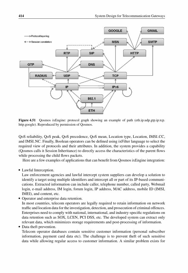
P1: OTA/XYZ P2: ABCc04 BLBK307-Bachmutsky September 2, 2010 13:18 Printer Name: Yet to Come
414 System Design for Telecommunication Gateways
Figure 4.51 Qosmos ixEngine: protocol graph showing an example of path (eth.ip.udp.gtp.ip.tcp.http.google). Reproduced by permission of Qosmos.
QoS reliability, QoS peak, QoS precedence, QoS mean, Location type, Location, IMSI CC,and IMSI NC. Finally, Boolean operators can be defined using ixFilter language to select therequired view of protocols and their attributes. In addition, the system provides a capability(Qosmos calls it Session Inheritance) to directly access the characteristics of the parent flowswhile processing the child flows packets.
Here are a few examples of applications that can benefit from Qosmos ixEngine integration:
� Lawful Interception.Law enforcement agencies and lawful intercept system suppliers can develop a solution toidentify a target using multiple identifiers and intercept all or part of its IP-based communi-cations. Extracted information can include caller, telephone number, called party, Webmaillogin, e-mail address, IM login, forum login, IP address, MAC address, mobile ID (IMSI,IMEI), and content, etc.
� Operator and enterprise data retention.In most countries, telecom operators are legally required to retain information on networktraffic and location data for the investigation, detection, and prosecution of criminal offences.Enterprises need to comply with national, international, and industry-specific regulations ondata retention such as SOX, LCEN, PCI DSS, etc. The developed system can extract onlyrelevant data, which minimizes storage requirements and post-processing of information.
� Data theft prevention.Telecom operator databases contain sensitive customer information (personal subscriberinformation, payment card data etc). The challenge is to prevent theft of such sensitivedata while allowing regular access to customer information. A similar problem exists for
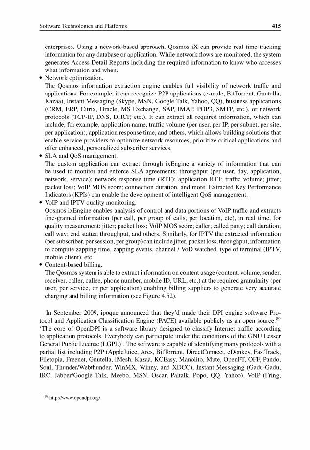
P1: OTA/XYZ P2: ABCc04 BLBK307-Bachmutsky September 2, 2010 13:18 Printer Name: Yet to Come
Software Technologies and Platforms 415
enterprises. Using a network-based approach, Qosmos iX can provide real time trackinginformation for any database or application. While network flows are monitored, the systemgenerates Access Detail Reports including the required information to know who accesseswhat information and when.
� Network optimization.The Qosmos information extraction engine enables full visibility of network traffic andapplications. For example, it can recognize P2P applications (e-mule, BitTorrent, Gnutella,Kazaa), Instant Messaging (Skype, MSN, Google Talk, Yahoo, QQ), business applications(CRM, ERP, Citrix, Oracle, MS Exchange, SAP, IMAP, POP3, SMTP, etc.), or networkprotocols (TCP-IP, DNS, DHCP, etc.). It can extract all required information, which caninclude, for example, application name, traffic volume (per user, per IP, per subnet, per site,per application), application response time, and others, which allows building solutions thatenable service providers to optimize network resources, prioritize critical applications andoffer enhanced, personalized subscriber services.
� SLA and QoS management.The custom application can extract through ixEngine a variety of information that canbe used to monitor and enforce SLA agreements: throughput (per user, day, application,network, service); network response time (RTT); application RTT; traffic volume; jitter;packet loss; VoIP MOS score; connection duration, and more. Extracted Key PerformanceIndicators (KPIs) can enable the development of intelligent QoS management.
� VoIP and IPTV quality monitoring.Qosmos ixEngine enables analysis of control and data portions of VoIP traffic and extractsfine-grained information (per call, per group of calls, per location, etc), in real time, forquality measurement: jitter; packet loss; VoIP MOS score; caller; called party; call duration;call way; end status; throughput, and others. Similarly, for IPTV the extracted information(per subscriber, per session, per group) can include jitter, packet loss, throughput, informationto compute zapping time, zapping events, channel / VoD watched, type of terminal (IPTV,mobile client), etc.
� Content-based billing.The Qosmos system is able to extract information on content usage (content, volume, sender,receiver, caller, callee, phone number, mobile ID, URL, etc.) at the required granularity (peruser, per service, or per application) enabling billing suppliers to generate very accuratecharging and billing information (see Figure 4.52).
In September 2009, ipoque announced that they’d made their DPI engine software Pro-tocol and Application Classification Engine (PACE) available publicly as an open source:89
‘The core of OpenDPI is a software library designed to classify Internet traffic accordingto application protocols. Everybody can participate under the conditions of the GNU LesserGeneral Public License (LGPL)’. The software is capable of identifying many protocols with apartial list including P2P (AppleJuice, Ares, BitTorrent, DirectConnect, eDonkey, FastTrack,Filetopia, Freenet, Gnutella, iMesh, Kazaa, KCEasy, Manolito, Mute, OpenFT, OFF, Pando,Soul, Thunder/Webthunder, WinMX, Winny, and XDCC), Instant Messaging (Gadu-Gadu,IRC, Jabber/Google Talk, Meebo, MSN, Oscar, Paltalk, Popo, QQ, Yahoo), VoIP (Fring,
89 http://www.opendpi.org/.
P1: OTA/XYZ P2: ABCc04 BLBK307-Bachmutsky September 2, 2010 13:18 Printer Name: Yet to Come
416 System Design for Telecommunication Gateways
IP
BaseStationSystem (BSS)
ServingGPRSSupport Node(SGSN)
HomeLocationRegister (HLR)
ChargingSystem
AuthorizationAuthentication& Accounting (AAA)Server
Gateway GPRSSupport Node(GGSN)
IP basedGPRS / UMTS
Network
Internet
AlternativePublic Land
Mobile Network
embedded into GGSN
CDR
Figure 4.52 Intelligent GGSN with integrated Qosmos ixEngine. Reproduced by permission ofQosmos.
H.323, IAX, Iskoot, MGCP, ooVoo, RTCP, SIP, Skinny, Skype), legacy protocols (BGP,DHCP, DDL, DNS, EGP, FTP, HTTP, ICMP, IGMP, IMAP, NETBIOS, NFS, NTP, OSPF,pcAnywhere, POP3, RDP, SMB/CIFS, SMTP, SNMP, SSDP, STUN, Telnet, Usenet, VNC,XDMCP), media streaming protocols and applications (AVI, Feidian, Flash, Icecast, Kon-tiki, MMS, Move, MPEG, OGG, ORB, PPLive, PPStream, QQ, QuickTime, Real MediaStream, RTP, RTSP, SCTP, SHOUTcast, Slingbox, SopCast, TVAnts, TVUPlayer, UUSee, VCAST, VeohTV, Windows Media Stream, Zattoo), tunneling protocols and applications (GRE,HamachiVPN, IPsec, L2TP, OpenVPN, SoftEthernet, SSL, SSH, Tor, VPN-X, VTun), gamingprotocols and applications (Battlefield, CGA Games, Google Earth, Half-Life 2 and Mods,Halo, Lively, Popo Game, Quake, QQ Game, Second Life, Sina Game, Spellforce, Steam,Vietcong, Warcraft 3, World of Warcraft, Xbox), and business-related protocols (citrix, LDAP,MSSQL, MySQL, Kerberos, PostgreSQL, SQL, SAP).
Other software that may be useful for some products based on Cavium Networks OCTEONprocessors is the hardware-optimized Cavium Networks software toolkits, including TCP,SSL, IPsec, SRTP for secure VoIP, SNORTXL for IDS/IPS, real-time anti-virus gateway, andClamXL for stored data virus scanning.
Let us also not forget a huge library of networking protocols from Continuous Computingand other suppliers. We have already mentioned ready-made protocols available from NPUvendors for their devices (see Section 3.5.3.2).

P1: OTA/XYZ P2: ABCc04 BLBK307-Bachmutsky September 2, 2010 13:18 Printer Name: Yet to Come
Software Technologies and Platforms 417
4.3 Single-Threaded and Multi-X Software Designs
For a better understanding of the available parallel solutions, let us review some of the differentforms of parallelism:
� Instruction level parallelism.This is the hardware-based parallelism found in two or more different instructions. In somecases, instructions can be executed in parallel if, for example, they execute operations intotally different registers. Many chip vendors are trying to achieve better CPU performanceby searching for instructions in the code that can be executed simultaneously. The searchfor dependencies among instructions usually complicates the pipeline of the chip.
� Data level parallelism.This is the parallelism inherent in the program’s data. If there is no dependency betweenvalues of one variable and another variable, both calculations can be executed in parallel.Data level parallelism can be difficult to determine if the program uses pointer arithmetic.However, if the program is written in a plain and simple way, the parallelism can be found andtraced. Data level parallelism is usually exploited by SIMD instructions in some processorarchitectures. It is used very efficiently in GPUs.
� Task level parallelism.The dependencies of this higher level parallelism are defined among sequences of code. Thealgorithm might have parallelism at both the instruction level and task level. For example,scanning the same pictures for different patterns enables multiple instruction streams, whichgenerate different data access pattern to the memory to determine which pattern can befound and what is its location. Usually, it is not possible to take the entire written programand decompose it into task level parallelism without redesigning the algorithm. The divisionof the program into functional threads is also one way to exploit task level parallelism.
An important property of task level parallelism is code granularity, or the size of thecode executed in a given task. There are three major levels of granularity: fine-grained taskwith tens or fewer instructions, medium-grained task with tens to hundreds of instructionsand a coarse-grained task with more than a few hundreds instructions as in threads inmulti-threaded operating systems.
The efficiency of various forms of task granularity depends mostly on a system’sscheduling and synchronization capabilities. A fine-grained program running on an inef-ficient scheduler will run slower than a serial program. If hardware thread or core switchingtakes too many cycles, the efficiency of parallelism drops significantly. Therefore, manymulticore and hardware multithreaded CPUs and NPUs have extremely short, frequentlyzero cycles, scheduling time. It becomes especially critical in fine-grained processors likePlurality (see Sections 3.5.6.2.8 and 4.3.8).
This chapter provides a comparison of the most popular software designs in telecommuni-cation gateways – from Single-Threaded Design (STD) where the application is assumed toown all available resources to what we call Multi-X Designs: Multi-Threaded Design (MTD)where multiple threads share some or all resources in the system, Multi-Process Design (MPD)that provides additional layer of hierarchy on top of MTD for memory protection and easiersoftware management, Multi-Instance Design (MID) that adds one layer on top of MPD to

P1: OTA/XYZ P2: ABCc04 BLBK307-Bachmutsky September 2, 2010 13:18 Printer Name: Yet to Come
418 System Design for Telecommunication Gateways
improve performance and resiliency, and MultiCore Design (MCD) that adds specifics ofdesigns for new generation of multicore CPUs.
This chapter also discusses the relationship between platform and application software forthe data and control plane.
Every scheme described here has some advantages and disadvantages. Every scheme canbe used and is used in different products. That’s why we will not use such terms as ‘right’and ‘wrong’, because generally speaking there are no wrong ones, there are just those that arebetter and worse fitted for a specific product. This Chapter provides a number of practical tipson the selection of the most appropriate software paradigm for the particular circumstances.
4.3.1 Industry Opinions about Different Design Types
There are different and even opposing opinions regarding the usage of different design types.We obtained a few of them from different user levels, from architects to programmers.
Catherine Crawford, IBM’s Chief Architect, provided many of reasons why their currentsoftware will be extremely inefficient in using the huge processing power of the next generationmulticore processors (Intel has already stated that all of their server processors are nowmulticore; and the same happens with our desktops and laptops with netbooks to follow; donot be surprised to see them soon in our PDAs and smartphones).90
One of PCWorld bloggers’ questions was whether software multithreading is at a dead-end because of its notoriously difficult programming with higher returns from efforts tospeed-up the single-threaded application than to port the same application to a multi-threadedenvironment.91
A similar comment from a TechRepublic blogger92 raised many of the problems discussedlater in this chapter, claiming that multithreading is ‘a dead-end’, that it is inflexible andexcessive and not a good fit for multicore and parallel programming.
Exactly the opposite comment came from one of the Yahoo! programmers,93 calling forsupport and encouragement for multi-threading programming.
The high level of frustration in some of the negative comments is obvious and is basedon the fact that software multithreading is far behind hardware multithreading and multi-core in terms of the development of competency, algorithm designs and redesigns, softwareparallelization study and tools, identification of potentially parallel paths in any computingenvironment and many other related activities, including assignment of corporate budgets forparallelization tasks. For example, not long ago the author participated in a discussion aboutthe applicability of multicore and multithreading concepts to some of the radio network proto-cols and modules. The discussion focused on some modules that are mostly serial today. Oneof the immediate questions was whether it was possible to make them parallel. The answer
90 Catherine Crawford, ‘Where’s The Software To Catch Up To Multicore Computing?’ EE Times, January 2007,http://www.informationweek.com/news/showArticle.jhtml?articleID=197001130.
91 PCWorld blog comment on multi-threading: http://blogs.pcworld.co.nz/pcworld/techsploder/2007/05/is_multithreading_a_dead_end.html.
92 TechRepublic blog comment on multi-threading: http://techrepublic.com.com/5208–12845-0.html?forumID=102&threadID=249701&messageID=2396371.
93 Yahoo! Programmer comment on multi-threading: http://valleywag.com/tech/yahoo/deadend-infrastructure-229027.php?mail2=true.
P1: OTA/XYZ P2: ABCc04 BLBK307-Bachmutsky September 2, 2010 13:18 Printer Name: Yet to Come
Software Technologies and Platforms 419
was positive, but this would require the development of different algorithms and probablechanges in the standardization of protocols. This example illustrates one aspect of the prob-lem, which is the need in at least some cases for basic redesign effort and a dependency on otherlegacy components, including standardization. And since the software development element ofthe project is often more expensive than hardware development, it can be easier to upgradethe hardware with a higher frequency CPU or add another CPU, or just load balance multiplecores in the CPU with every instance running in a single-threaded mode, than reinventingthe algorithm enabling parallelization.
In general, there are three main reasons for parallelization, or as Herb Sutter and hiscolleague David Callahan from Microsoft call them ‘pillars’ [Concurrency-Pillars]:
� The need for responsiveness and isolation. One example from the telecommunication fieldwould be control, data and management plane handling.
� The need for throughput and scalability. For example, we can take an application designed forhandling of 100 users and replicate it 100 times with some kind of load balancing betweenthese instances to handle 10 K users without significant software redesign. Similarly, ifone instance can handle 100 events per second, 100 parallel instances with efficient loadbalancing can handle close to 10 K events per second if they use separate or efficientlyshared computing resources.
� The need for consistency achieved through the synchronization for shared resources ac-cess. Multiple concurrent functions in the product could use the same resource and thesynchronization between parallel running tasks can prevent its unintended corruption.
The sections below try to build a foundation out of a number of basic concurrency conceptsthat are helping to make a successful transition into the new ‘parallel world’.
4.3.2 Single-Threaded Design
Single-threaded design (STD) is the ‘old’ school software architecture, where one monolithicmodule takes all of the available resources in terms of CPU cycles, memories, interfaces, etc.One of the biggest advantages of STD is its inherent simplicity, because there is no needto share any resources or to be aware of any other module that can destroy the memoryor mishandle an event. On the other hand, STD has a comparably large disadvantage: theefficiency of CPU usage for large set of applications.
To understand the reasons for this disadvantage, it is important to analyse the software andhardware behavior. Even pure computational implementations need to get at some point of timean input from external devices (network or man-machine interfaces, tapes, disks and others)or generate output to these external devices. Such devices operate normally at a much slowerspeed compared to the CPU and thus it is common to find the CPU waiting for an operationto finish before continuing further processing. In addition, a processor today is not just pureCPU; it includes many tightly integrated subsystems such as memory and memory controllers,interrupts and interrupt controllers, interfaces and interface controllers and so on. While beingfaster than the external devices, hardware internal devices are still significantly slower thanthe CPU, itself causing loss of expensive CPU cycles for every access. For example, if a CPU

P1: OTA/XYZ P2: ABCc04 BLBK307-Bachmutsky September 2, 2010 13:18 Printer Name: Yet to Come
420 System Design for Telecommunication Gateways
instruction can take only one or few cycles while using internal registers, the memory accesscan take anywhere between tens and hundreds of CPU cycles.
Let us create a simple pseudo-code based on STD for a networking application responsiblefor receiving a packet, its processing and sending a response back to the same interface. It canlook something like the following:
forever {receive (packet, interface); process (packet); send(packet);}
We can see that CPU cycles will not be used when there are no packets to process. Anotherobservation is that after the packet is received, the loop (and total performance) is defined bythe complexity of the processing: the next packet will not be received and processed until theprevious one is completed. It means that packets requiring heavy work will create high latency(time between packet receive and packet send), because packets will be waiting for their turnto be processed. There is one more parameter that might be considered as even worse forsome applications: the jitter, or latency variation. In our example different packets will requirepotentially different processing times causing highly variable latencies and as a result a highjitter. For system involving audio and video processing, the jitter is a killer, and minimizingjitter is extremely important.
Hardware has been trying to ease the problem of lost cycles for a long time. One way hasalways been a brute force solution to create more cycles; this is where we see higher andhigher frequencies of CPUs. This was the preferred path for a long time. We cannot say thatit is not important today and CPU frequency is still a major item for comparison betweendifferent processors; however, there are many other differentiators. One of them is creatingcomplex multi-issue instruction pipelines with predictive branches, when the processor loadsmultiple instructions at a time, tries to predict what instructions will be running next andexecutes multiple instructions in parallel; the problem arises where such predictions are notgood enough and there is a need to load different instructions, paying a penalty of lost CPUcycles. This is the reason why there is an attempt to design instruction pipelines to be as shortas possible, causing some changes in the hardware design paradigm. Yet another way is tooptimize the architecture of internal devices with either higher speeds (which can be referred toagain as a brute force; you can see it in all of the announcements of higher front side bus speedscoming from Intel, AMD and other processors) or more advanced designs (switches insteadof buses, multi-layer access like L1-L2-L3 caches for memory, etc.). Actually, in most casesthere is all of the above in existing high-end CPUs. All of these techniques help to reduce lossof cycles due to the internal devices, but they do not bring and cannot be the ultimate solution.
Because of all of its inefficiencies, STD is viewed normally as inflexible and unsatisfactoryfor many applications and there is a huge effort to redesign existing single-threaded imple-mentations to be multi-threaded. However, the STD is still there. Moreover, the STD has seenan unexpected ‘renaissance’ lately.
To understand this phenomenon, we would like to use the example of the current versionof the Internet based on the Internet Protocol (IP). There are two versions of that protocol,version 4 and version 6. IP version 4 (IPv4) has existed for a long time and is based on 32-bit

P1: OTA/XYZ P2: ABCc04 BLBK307-Bachmutsky September 2, 2010 13:18 Printer Name: Yet to Come
Software Technologies and Platforms 421
end-user addresses; the Internet outgrew that number of users a long time ago. IP version 6(IPv6) allows much larger number of users. This is the reason why for years we have heardthat IPv4 is dead and that everything has to become based on IPv6. It has still not happened,and many of us will continue to use IPv4 for many years to come to access various Internetservices. The major force behind this is the ingenuity of low-cost solutions designed to prolongthe lifetime of IPv4, including the private networks and network address translation that wesee in every home gateway today.
Similarly, a number of approaches are used to prolong the life of STD. One of them isvirtualization (discussed in more detail in Section 4.4) which allows multiple single-threadedapplications to use the same CPU resources; assuming that not all such applications alwaysaccess internal and external devices at the same time, CPU utilization becomes much higher,because one application can run while another is waiting for the device response. Usingvirtualization, the pseudocode above can be modified as follows:
VM1: forever {receive (packet, interface1); process (packet); send(packet);}VM2: forever {receive (packet, interface2); process (packet); send(packet);}
In this example, when one application is waiting for a packet on one interface another canprocess packets from a different interface. It can be argued that we can solve the same problemwithout virtualization by modifying the code to be as follows:
forever {receive (packet, any-interface); process (packet); send(packet);}
This is a valid argument assuming that we have the capability to receive packets fromany interface; and this is precisely how it is used for applications with simple processingsuch as IPv4 forwarding. On the other hand, we will hit the next bottleneck during the packetprocessing phase. Let us complicate the example slightly and assume that the packet processingincludes packet validation, packet decryption by external device, some packet modificationand packet encryption by external device after modification:
forever {receive (packet, any-interface); validate (packet);ext-decrypt(packet); modify(packet); ext-encrypt(packet); send(packet);}
This more complex code created two additional wait states during packet processing: waitingfor decryption and waiting for encryption. Without virtualization we would need to processall packets one-by-one. Let us add virtualization:

P1: OTA/XYZ P2: ABCc04 BLBK307-Bachmutsky September 2, 2010 13:18 Printer Name: Yet to Come
422 System Design for Telecommunication Gateways
VM1: forever {receive (packet, any-interface); validate (packet);ext-decrypt(packet); modify(packet); ext-encrypt(packet); send(packet);}VM2: forever {receive (packet, any-interface); validate (packet);ext-decrypt(packet); modify(packet); ext-encrypt(packet); send(packet);}
Now we have, for example, the capability to receive and validate the next packet while theprevious packet is being sent for decryption. In general, it is possible to modify the originalexample and achieve a similar effect without virtualization (one option is to remember a statefor every packet and restart the loop while waiting for a cryptographic function to return theresult), but the code becomes more complex to develop, debug and maintain. In any case,these modification arguments might not be relevant when we are talking about the legacy codethat nobody wants to touch. Virtualization enables the achievement of some level of parallelprocessing without modifying the STD application.
A second approach worth mentioning here is again, not surprisingly, hardware-based bruteforce. One example would be a dynamic acceleration feature where the heavily workingCPU is ‘overclocked’, providing a boost to performance when needed, while potentially‘underclocking’ other CPUs or resources. We still do not use CPU cycles while waiting, buton the other hand we have more cycles during short burst periods (it has to be short enoughto avoid CPU overheating during the overclocked operation and the time depends on theimplementation and overclocking ratio); and this approach is indeed used by some processors.The problem with this approach is that few processors are designed with the capability tobe overclocked even statically, not to mention dynamic core clock boost. For example, thevery advanced latest generation of processors from Cavium Networks, NetLogic, Freescale,AppliedMicro, LSI and many other vendors does not have (or at least does not advertise) sucha capability.
Another approach is the enhancement of the processing architecture achieved, for example,by data and control planes separation. Many applications have at least two distinct processingtypes: one has a large amount of events with relatively ‘simple’ processing for each event,while the other has a smaller amount of events, although each event requires much morecomplex processing. One example is a networking application in routers that can be dividedinto routing (running routing protocols – OSPD, BGP, etc. – and exchanging routing tablesbetween networking infrastructure devices as opposed to end-user devices) and forwarding(passing user packets from one interface to another). Fast and simple processing can beperformed much more efficiently using the STD principles which provided impetus for thenew breed of hardware devices based on FPGAs, ASICs and NPUs described in Section3.4.3. We have also seen lately the re-appearance of single-threaded bare-metal operatingsystems that support the STD. Such OSs are sometimes called a ‘simple executive’ and have asingle-loop run-till-completion implementation providing an efficient processing environmentwithout any scheduling challenges and overheads.
Results can be improved if several approaches are combined. For example, a combinationof virtualization with data/control plane separation would create the following example (herewe give control over all interfaces to the data plane processing application):

P1: OTA/XYZ P2: ABCc04 BLBK307-Bachmutsky September 2, 2010 13:18 Printer Name: Yet to Come
Software Technologies and Platforms 423
VM1: forever {receive (packet, any-interface-or-application);if (received-from-application) send(packet);else if (it-is-control-plane(packet)) thensend-to-control-plane(packet, Application2);else{process-data-plane(packet); send (packet);}
}VM2: forever {receive (packet, Application1); process-control-plane(packet); send (packet, Application1);}
Of course, on a single CPU we would still use many cycles for control plane processing,but with the virtualization-based STD we can assign a priority and scheduling algorithm forthe data and control plane similar to a multi-threaded application. The largest boost from theconcept above will be found in multicore processors.
The STD has been described for some time as a dead-end in software design. We candefinitely say today that this was ‘a little’ premature. We are also aware of some voices,mentioned previously, that describe multi-threaded designs as a dead-end because of theircomplexity. In our humble opinion both designs will stay for a while and will be applied whenseen as an appropriate solution by software and system architects.
4.3.3 Multi-Threaded Design
MTD designs solve problems not addressed by the STD. They are based on the divisionof applications into multiple processing threads. While the boundary between threads variesfrom application to application and even between different implementations of the sameapplication, we will limit this chapter to function-based multi-threading, leaving other aspectsof the division of applications into multi-instance designs to the next chapter.
Multi-threading can achieve some level of hardware assist with three major implementations:(a) the interleaved MTD, when a thread is being switched for every instruction; the switchingcan be static or dynamic, with predictable behavior for the static one and more flexible, lesspredictable and more complex dynamic switching; (b) the blocked MTD, when a thread isswitched when the processing is suspended for any reason (external memory access, cachemiss, etc.); it is much easier to implement this than the dynamic interleaved MTD, howevera single thread can take the entire CPU for a long period of time, causing potential starvationof other threads; (c) the simultaneous MTD, where instructions from multiple threads areprocessed concurrently, by far the most complex implementation of all. It is important toemphasize that hardware assist in most cases includes thread switching in hardware (in someimplementations it is a zero-cycle switch), saving many cycles on storing/restoring registers,handling instruction pipelines, pre-fetching caches, etc. Usually, OS with MTD support takescare of all required hardware support and hides that complexity from the application layer; ifthe specific hardware support does not exist, it is emulated by OS in software, which is stillhidden from the application, but is expensive from the CPU utilization point of view.

P1: OTA/XYZ P2: ABCc04 BLBK307-Bachmutsky September 2, 2010 13:18 Printer Name: Yet to Come
424 System Design for Telecommunication Gateways
There are multiple forces behind the MTD. The first is to improve CPU utilization by runningsome other tasks when one is accessing internal or external devices or not fully utilizing allCPU blocks (each separate instruction does not utilize all of the CPU’s capabilities, but usesonly its subset).
The second force is to simplify programming by making a single software unit smaller.This is achieved by dividing the application into functional blocks with, as far as possible,independent development, testing, load and upgrade, taking into account the limited communi-cation or data sharing between functions. We can take one function – for example, in-memorydatabase management – and develop and debug it mostly independently assuming that wehave defined precisely all of the interfaces between this particular function and the rest ofthe system. Moreover, we can potentially maintain it separately, fix bugs and add featureswithout recompiling other functions if there is no change in the external function interfaces.Of course, in some cases there can be a separate development without multi-threading, withlinked libraries being one example; however, it has many limitations, because a library runsin the context of the calling thread that forces particular memory mapping and protectionsettings. In addition, some functions might require independent behavior. For example, au-thentication might require triggers from other application functions, but usually has its ownconnections to authentication servers with corresponding state management, session manage-ment, reliability management and many others; which would in practice push for separateauthentication thread(s) in many systems. When dependency between functions becomes toolarge, such as sharing and updating many common objects, the MTD can become an inefficientchoice.
The third force behind the MTD surfaced not so long ago: hardware multithreaded andmulticore processors. Without virtualization, MTD and multi-instance designs, single-threadedapplications cannot take advantage of multiple cores (a hardware thread can be viewed as acore from a software point of view). This becomes even more critical when we realize thatmulticore processors run normally with a significantly lower core frequency compared tosinglecore processors reducing the comparable single core performance, which means that thesame STD application runs potentially on a multicore processor with a lower performance.For example, such an application could run slower on a quad-core 2.66GHz Intel CoreTM2processor than on a relatively ‘old’ 3.4GHz Intel Pentium, because only a single core is utilizedat any point in time.
The MTD is often based on a functional division, where different functions are imple-mented as separate threads or sets of threads. For example, in Mobility Gateway we wouldhave thread(s) for authentication, mobility, accounting, security, emergency services, lawfulinterception and others. Function-specific threads are especially popular in control plane im-plementation, which is considered to be much more complex, has a large amount of code (canbe millions lines of code for some products) and is not suitable for a monolithic STD.
Unfortunately, the MTD also has its negative side. Multi-threading is viewed as one ofthe biggest (if not the biggest) nightmares for software developers and is the source of theworst problems during the development, debugging and maintenance. Not only are theseproblems severe and frequently cause fatal crashes, but it is also much more difficult to debugsuch problems, and almost every MTD-based project goes through a number of such bugswith weeks and months of fruitless debugging trying to catch a rarely occurring fault createdby a ‘unique’ combination of triggers causing memory corruption, out-of-order processing,disappearance of events and internal resources and similar.
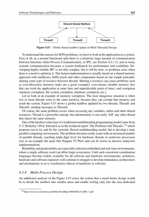
P1: OTA/XYZ P2: ABCc04 BLBK307-Bachmutsky September 2, 2010 13:18 Printer Name: Yet to Come
Software Technologies and Platforms 425
Shared Global Mailbox
Thread1 Thread2 Thread3
Figure 4.53 Global shared mailbox update in Multi-Threaded Design.
To understand the reasons for MTD problems, we have to look at the application as a system.First of all, in a normal functional split there is a relatively large amount of communicationbetween functions (Inter-Process Communication, or IPC, see Section 4.2.1.3), and in manysystems communication becomes a system bottleneck for performance and scalability. De-veloping highly reliable IPC is not that complex, but it will be slow, so problems arise whenthere is a need to optimize it. The fastest implementation is usually based on a shared memoryapproach with mailboxes, buffer pools and other components based on one simple principle:sharing some type of resource between threads. Sharing a resource can cause problems suchas over-allocation (memory leaks are a good example), over-release (double memory freethat can crash the application at some later and unpredictable point of time), and corruption(memory corruption, file system corruption, database corruption, etc.).
Let us look at an example of memory corruption. The most dangerous situation is whentwo or more threads write to the same memory, because they can corrupt that memory andcrash the system. Figure 4.53 shows a global mailbox updated by two threads, Thread1 andThread3, sending messages to Thread2.
Of course, the same problem occurs when accessing any variables, tables and other sharedresources. Thread is a powerful concept, but unfortunately it can easily ‘kill’ any other threadthat shares the same memory.
One of the harshest criticisms of a traditional multithreading programming model came fromU. C Berkeley’s Prof. Edward Lee in the technical report ‘The Problem with Threads’,94 whichproposes not to try and fix the currently flawed multithreading model, but to develop a trulyparallel computing environment. The problem becomes really acute with an increased numberof parallel threads, reaching triple-digit level for hardware threads in multicore processors(see as an example the quad Sun Niagara T2 Plus) and can be worse in massive manycoreimplementations.
Reliability and predictability are especially critical in embedded and real-time environments,where a single software crash can affect large ecosystems. Until such concurrent coordinationlanguages become widely available for all software and hardware environments, architects,hardware and software engineers will continue to struggle to develop redundancy architecturesand mechanisms so as to synchronize objects in hardware or software.
4.3.4 Multi-Process Design
An additional analysis of the Figure 4.53 raises the notion that a much better design wouldbe to divide the mailbox into smaller areas and enable writing only into the area dedicated
94 http://www.eecs.berkeley.edu/Pubs/TechRpts/2006/EECS-2006–1.pdf.
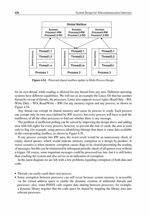
P1: OTA/XYZ P2: ABCc04 BLBK307-Bachmutsky September 2, 2010 13:18 Printer Name: Yet to Come
426 System Design for Telecommunication Gateways
Global Mailbox
Thread1.1 Thread2.1 Thread3.1
Access: Process1-RW
Process2,3-RO
Access: Process2-RW
Process1,3-RO
Access: Process3-RW
Process1,2-RO
Thread1.2
. . . . . . . . .
Thread1.n
Thread2.2
Thread2.m
Thread3.2
Thread3.lSh
ared
mem
ory
Sh
ared
mem
ory
Sh
ared
mem
ory
Process 1 Process 2 Process 3
Figure 4.54 Protected shared mailbox update in Multi-Process Design.
for its own thread, while reading is allowed for any thread from any area. Different operatingsystems have different capabilities. We will use as an example the Linux OS that has anotherhierarchy on top of threads, the processes. Linux also supports access rights (Read Only – RO,Write Only – WO, Read/Write – RW) for any memory region and any process, as shown inFigure 4.54.
Any thread can corrupt its shared memory and cause its process to crash. Each processcan corrupt only its own area (defined by RW access), but every process will have to poll themailboxes of all the other processes to find out whether there is any message.
The problem of inefficient polling can be solved by improving the design above and addingarea with full rights for every process; however, to prevent the risk of crash, the area is usedonly to flag (for example, using process-identifying bitmap) that there is some data availablein the corresponding mailbox, as shown in Figure 4.55.
If any process corrupts this RW area, the worst result would be an unnecessary check ofempty shared queues, which would indicate memory corruption as a design by-product. Aworse scenario is when memory corruption causes flags to be cleared preventing the readingof messages, but this can be minimized by infrequent periodic check of all queues even withouta trigger. Of course, some important messages could be processed too late, but it is still betterthan crashing the system and also serves as an indication of corruption.
In the latest diagram we are left with a few problems regarding corruption of both data andcode:
� Threads can easily crash their own process.� Some corruption between processes can still occur because system memory is accessible
via the virtual address space to enable the dynamic creation of additional threads andprocesses; also, some POSIX calls require data sharing between processes; for example,a dynamic library requires that the code space be shared by mapping the library area intorelevant processes.

P1: OTA/XYZ P2: ABCc04 BLBK307-Bachmutsky September 2, 2010 13:18 Printer Name: Yet to Come
Software Technologies and Platforms 427
Global Mailbox
Thread1.1 Thread2.1 Thread3.1
Access: Process1-RW
Process2,3-RO
Access: Process2-RW
Process1,3-RO
Access: Process3-RW
Process1,2-RO
Thread1.2
. . . . . . . . .
Thread1.n
Thread2.2
Thread2.m
Thread3.2
Thread3.lSh
ared
mem
ory
Sh
ared
mem
ory
Sh
ared
mem
ory
Process 1 Process 2 Process 3
Access: All - RW Access: All - RW Access: All - RW
Figure 4.55 Protected shared mailbox and ‘semaphore’ update in Multi-Process Design.
� The damage after memory corruption can be indirect: even a reading only process cancorrupt its own memory or crash based on the corrupted data read and a chain reaction canstill bring down the entire system.
There are a number of guidelines to be considered when using the MTD or the MPD:
� A process provides better memory protection as compared to a thread. Virtual machineshave better protection than processes.
� A process is loaded and unloaded dynamically together with all its threads and used re-sources, providing potentially simpler software management.
� Some OSs could be sensitive to a number of processes either from a scalability point of viewor a scheduling performance, but we do not expect a significant problem with, for example,Linux 2.6, which supports up to 32 K threads and 32 K processes with a fairly efficientscheduling algorithm.
� It is a good policy to protect shared memory with some kind of checksum (preferably,CRC) being updated with every full modification operation similar to database commit;the checksum has to be verified frequently; multiple latest generation processors providehardware acceleration in some form for a checksum/CRC calculation.
� Sanity checks and data validation (especially pointers) are required when reading from ashared memory, even when the performance is affected. The general rule is that it is betterto have a lower performance stable system than slightly higher performance, but crashingoccasionally.
Usually, the MPD concept means working with OS-level processes. Other solutions includea family of concurrent programming languages. Erlang is one such language with much
P1: OTA/XYZ P2: ABCc04 BLBK307-Bachmutsky September 2, 2010 13:18 Printer Name: Yet to Come
428 System Design for Telecommunication Gateways
experience in telecommunication applications, because it was created and used by Ericssonand became an open source in 1998. Erlang was designed for heavily distributed and parallelsystems. It creates and manages processes internally and these low-overhead processes donot share any memory (there is also the Erlang VM version that uses POSIX threads andshared memory) and communicate through asynchronous messaging primitives and integratedmailbox. This is done for a higher reliability to make sure that one process cannot corrupt thedata belonging to any other process. Erlang’s scalability in terms of the number of processesis extremely high and one report cited a test running with 20 million processes in a ringmessage-passing application by making inactive message-waiting processes hibernate. Fewsystems can claim to have such a level of scalability. On the other hand, some benchmarksshow that Erlang does not scale well beyond a particular number of cores (one of the testsperformed with Tilera TILEPro64 shows a drop in performance after thirty-two cores; anothertest with very poor results is chameneos redux in the Computer Language Shootout), whichmeans that not all applications and environments are beneficial for this language.
4.3.5 Multi-Instance Design
There are multiple factors in multi-instance design. One relates to multiple instances ofprocessing entities in the system (for example, multiple instances of control and data plane);another is related to multiple instances of the application.
Let us analyse initially multiple application instances. There are three main reasons for thistype of multi-instance: CPU usage efficiency (and performance as a result), implementationscalability and high availability. All three can be explained by the diagram below of a nodehandling mobile subscribers (MS).
The design in Figure 4.56 includes N identical (from a code point of view) control planeapplication instances that share a common global database. One of the important principlesin this design is to make these instances independent of each other as much as possible inorder to minimize communication between them. This is achieved through the load balancingscheme where every new MS is assigned to one of instances (it can be based on the statichashing of mobile subscriber ID, MSID, pure round robin, weighted round robin, instanceload information or other algorithms) and from this point forward there is an affinity betweenthe MS and the instance for the entire lifetime of that subscriber within the box, until iteither disconnects or moves to the service area of another box. Assuming an efficient loadbalancing algorithm selection and a large amount of subscribers, these instances should beloaded similarly. In some cases it is possible to move mobile subscribers between instances,but this is not a straight-forward implementation, requires a transfer of some records ordatabases between instances (most probably, for many functions) and the reconfiguration of aload balancing mechanism. It is still one of the viable solutions if considered to be a criticalcapability, but has to be approached with caution: simpler in many cases means better, becauseof faster development, fewer bugs and easier maintenance.
Every instance in the design is a full application implementation (functions A through D inthe example) that deals with some subset of all subscribers. In addition to the abovementionedlimited need for communication between these instances and a limited shared resource, eachinstance enjoys the memory protection available for the MPD or virtualization, minimizingthe probability of memory corruption between instances. An additional benefit stems from

P1: OTA/XYZ P2: ABCc04 BLBK307-Bachmutsky September 2, 2010 13:18 Printer Name: Yet to Come
Software Technologies and Platforms 429
Function-based MUX
Function A Function D
MS DBA
Thread A Thread D
Process 1 (Instance 1)
MS DBD
Function-based MUX
Function A Function D
MS DBA
MS DBSHAREDMS DBSHARED
Thread A Thread D
Process N (Instance N)
MS DBD
Global DBSHARED
MSID-based Instance MUX
Q1
QA QDQA QD
QN
Figure 4.56 Multi-Instance Control Plane Application.
the fact that every instance is processing different data at every point of time reducing theprobability that software failure will occur in multiple instances simultaneously. It brings ahigher availability advantage because software failure will affect only a subset of all subscribers(assuming a similar amount of subscribers in all instances, it would be approximately the 1/Nth)and there would be enough time to bring such an instance back and restore service to all thesesubscribers before the next failure. Of course, any failure is bad and undesirable, but bugshappen, some of them are fatal, and the design under review improves system behavior evenwhen it happens, without the need for complex stateful redundancy.
One component that is not shown in Figure 4.56 is an additional instance (we can call it theInstance 0) that is used for a global configuration, a functionality that is not subscriber-specific,the processing of unknown subscribers (error handling) and similar tasks.
To summarize, the design under review achieves the following:
� There are many (as many as we need) processes and threads to fill the CPU wait states:when the processing of one mobile subscriber is waiting for some event, another can beprocessed independently; this advantage becomes especially evident in systems with multipleprocessors and/or hardware multithreaded and multicore processors.
� The implementation of every instance is simpler because of lower scalability; as it waspointed out previously, each instance has to scale only to about 1/Nth of all subscribersand it is always simpler to implement the required functionality with lower scalability. Forexample, a system with tens of instances and a total scalability of 1 million subscribersneeds to have every instance supporting only tens of thousands of subscribers, which is asignificantly easier task.

P1: OTA/XYZ P2: ABCc04 BLBK307-Bachmutsky September 2, 2010 13:18 Printer Name: Yet to Come
430 System Design for Telecommunication Gateways
� The system has higher availability, because of a lower probability that a software bug willcause the entire box to go down; some requirements define that the node is marked asavailable if it can continue to serve at least half of its designated traffic and scalability, and insuch deployments the design above would bring the system close to a ‘magic’ carrier-classhigh availability number, 99.999% (also known as five nines).
There is a drawback to the proposed MID: a particular instance could become overloaded ifit experiences an unexpected burst in the events for a specific set of subscribers being servedby this instance. One way to circumvent the burst is to modify dynamically the load balancingscheme and move some subscribers to other less loaded instances; however, this is a complexprocedure as mentioned previously. There is another way to handle the burst, an idea borrowedfrom the pool-of-threads concept used in many products, including the Java. Pool-of-threads,for example, uses a generic concept of pre-allocated and ready-to-run multiple threads and canassign an extra thread to any function. Frequently, the burst involves one or a few particularfunctions in the instance, not all of them; therefore, it might be more efficient to preparefunction-specific extra threads if there is an expectation of a burst of specific events. Forexample, a burst of authentication events happens when a large passenger transport (ship,train, bus, airplane, etc.) enters the mobile network coverage area; to handle future burst, thesystem would pre-create multiple authentication threads and assign them as needed. Withthis concept in mind, the previous MID diagram can be modified slightly by adding multiplethreads for Function A, as shown in Figure 4.57.
Load balancing between the threads of the Function A can be done either on-demand, or allsubscribers can be subdivided between the multiple threads of the function.
Global DBSHARED
Function-based MUX
Function DThread D
Process 1 (Instance 1) Function-based MUX
Function DThread D
Process N (Instance N)
MSID-based Instance MUX
Q1
Function AThread A
Function AThread A
MS DBA
MS DBSHAREDMS DBSHARED
MS DBD MS DBDMS DBA
QAQD QA
QD
QN
Figure 4.57 Multi-Instance Control Plane Application with extra Pool-of-Threads.
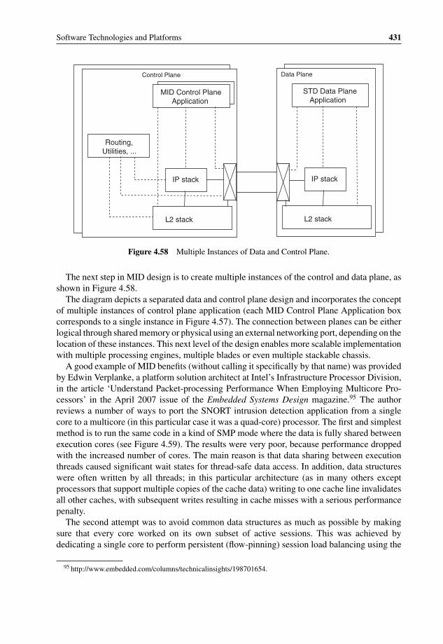
P1: OTA/XYZ P2: ABCc04 BLBK307-Bachmutsky September 2, 2010 13:18 Printer Name: Yet to Come
Software Technologies and Platforms 431
Data Plane
STD Data Plane Application
IP stack
L2 stack
Control Plane
IP stack
L2 stack
MID Control Plane Application
Routing, Utilities, ...
Figure 4.58 Multiple Instances of Data and Control Plane.
The next step in MID design is to create multiple instances of the control and data plane, asshown in Figure 4.58.
The diagram depicts a separated data and control plane design and incorporates the conceptof multiple instances of control plane application (each MID Control Plane Application boxcorresponds to a single instance in Figure 4.57). The connection between planes can be eitherlogical through shared memory or physical using an external networking port, depending on thelocation of these instances. This next level of the design enables more scalable implementationwith multiple processing engines, multiple blades or even multiple stackable chassis.
A good example of MID benefits (without calling it specifically by that name) was providedby Edwin Verplanke, a platform solution architect at Intel’s Infrastructure Processor Division,in the article ‘Understand Packet-processing Performance When Employing Multicore Pro-cessors’ in the April 2007 issue of the Embedded Systems Design magazine.95 The authorreviews a number of ways to port the SNORT intrusion detection application from a singlecore to a multicore (in this particular case it was a quad-core) processor. The first and simplestmethod is to run the same code in a kind of SMP mode where the data is fully shared betweenexecution cores (see Figure 4.59). The results were very poor, because performance droppedwith the increased number of cores. The main reason is that data sharing between executionthreads caused significant wait states for thread-safe data access. In addition, data structureswere often written by all threads; in this particular architecture (as in many others exceptprocessors that support multiple copies of the cache data) writing to one cache line invalidatesall other caches, with subsequent writes resulting in cache misses with a serious performancepenalty.
The second attempt was to avoid common data structures as much as possible by makingsure that every core worked on its own subset of active sessions. This was achieved bydedicating a single core to perform persistent (flow-pinning) session load balancing using the
95 http://www.embedded.com/columns/technicalinsights/198701654.

P1: OTA/XYZ P2: ABCc04 BLBK307-Bachmutsky September 2, 2010 13:18 Printer Name: Yet to Come
432 System Design for Telecommunication Gateways
Packet capture
Packet decoder
Preprocessors
Detection engine
Output plug-in
Snort dataflow
Core 4Snort dataflow
Core 3Snort dataflow
Core 2Snort dataflow
Core 1
Packet capture
Packet decoder
Preprocessors
Detection engine
Output plug-in
Snort dataflow
Figure 4.59 Snort migration from a single- to multicore. Reproduced by Intel.
hash function on source and destination IP addresses plus source and destination TCP ports(see Figure 4.60).
The article also confirmed another positive side effect of the architecture – smaller TCPreassembly tables (one third of the size in this case). As a result, with pipelining and persistentload balancing in place, the achieved throughput became more than 6.2x greater than asinglecore system.
As Intel’s practical example shows, multicore migration, especially using MID principles,can bring a significant performance boost, but multicore design has to be done very carefullyin order to minimize bottlenecks of different shared resources (data structures, caches, etc),including synchronization code and data locking semaphores.
4.3.6 Co-Location and Separation of Platform and Application
It is difficult to recommend a particular location of platform vs. application. Figure 4.58 showsthem co-located and this will be enough for some products. On the other hand, many productshave different platform and application requirements for both scalability and performance.
This is almost the norm when control plane traffic is not heavy from a throughput point ofview, but it has significant processing and high scalability requirements. One such product is theRadio Network Controller (RNC) in existing mobile networks. To be able to handle the entireRNC control plane efficiently, we can create many instances, but it will unnecessarily scale

P1: OTA/XYZ P2: ABCc04 BLBK307-Bachmutsky September 2, 2010 13:18 Printer Name: Yet to Come
Software Technologies and Platforms 433
Packet capture
Hash function
Core 1
Packet capture Packet capture Packet capture
Packet decoder Packet decoder Packet decoder
Preprocessors Preprocessors Preprocessors
Detection engine Detection engine Detection engine
Output plug-in Output plug-in Output plug-in
Core 4Core 3Core 2
Figure 4.60 Snort in multicore with persistent load balancing. Reproduced by Intel.
and complicate platform networking Layer 3 and Layer 2 stacks that are not always designedto run multiple instances. In addition, we probably do not really need such a high-performancenetworking stack in RNC, the control plane traffic is just not that high.
A similar observation can be made for the data plane: many products need a great dealmore processing for a data plane application as compared to a data plane platform, such as thecommunication Layer 2 and Layer 3 functionality, calling for an independent platform andapplication scalability.
A more scalable platform-application split design is shown in Figure 4.61.The proposed split-design detaches the data plane application from its platform by using
exposed APIs, including access to sockets and optionally Layer 2/Layer 3 networking stacks;data plane application instances do not need the complete networking stack, because they canuse a platform stack instead. The control plane application is also detached from the platform,its every instance includes a socket proxy with a standard socket API and this does not includethe networking stack. This socket proxy is responsible for redirecting socket requests tocontrol or data plane networking stacks. For instance, the latter can be used for a socket-based
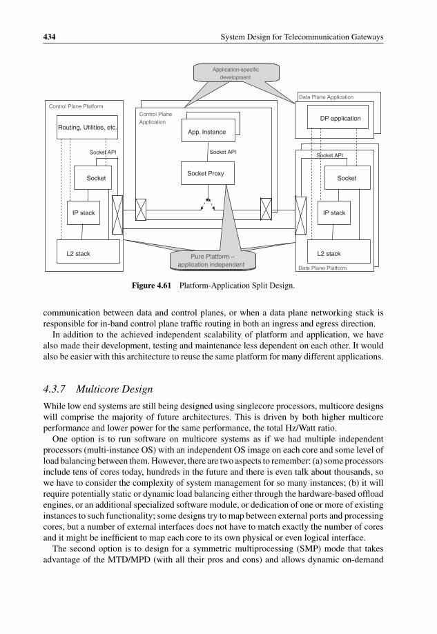
P1: OTA/XYZ P2: ABCc04 BLBK307-Bachmutsky September 2, 2010 13:18 Printer Name: Yet to Come
434 System Design for Telecommunication Gateways
Control Plane Application
App. Instance
Socket API
Socket Proxy
Data Plane Platform
DP application
Socket API
Socket
IP stack
L2 stack
Control Plane Platform
Routing, Utilities, etc.
Socket API
Socket
IP stack
L2 stack
Data Plane Application
Application-specific development
Pure Platform –application independent
Figure 4.61 Platform-Application Split Design.
communication between data and control planes, or when a data plane networking stack isresponsible for in-band control plane traffic routing in both an ingress and egress direction.
In addition to the achieved independent scalability of platform and application, we havealso made their development, testing and maintenance less dependent on each other. It wouldalso be easier with this architecture to reuse the same platform for many different applications.
4.3.7 Multicore Design
While low end systems are still being designed using singlecore processors, multicore designswill comprise the majority of future architectures. This is driven by both higher multicoreperformance and lower power for the same performance, the total Hz/Watt ratio.
One option is to run software on multicore systems as if we had multiple independentprocessors (multi-instance OS) with an independent OS image on each core and some level ofload balancing between them. However, there are two aspects to remember: (a) some processorsinclude tens of cores today, hundreds in the future and there is even talk about thousands, sowe have to consider the complexity of system management for so many instances; (b) it willrequire potentially static or dynamic load balancing either through the hardware-based offloadengines, or an additional specialized software module, or dedication of one or more of existinginstances to such functionality; some designs try to map between external ports and processingcores, but a number of external interfaces does not have to match exactly the number of coresand it might be inefficient to map each core to its own physical or even logical interface.
The second option is to design for a symmetric multiprocessing (SMP) mode that takesadvantage of the MTD/MPD (with all their pros and cons) and allows dynamic on-demand

P1: OTA/XYZ P2: ABCc04 BLBK307-Bachmutsky September 2, 2010 13:18 Printer Name: Yet to Come
Software Technologies and Platforms 435
scheduling of ready-to-run threads based on a relative thread priority and hardware thread/coreavailability. A single SMP OS deals with many threads and the SMP is supported by allmajor OSs, including Linux; and scheduling algorithms are also very advanced today. SMPprogramming is relatively straight-forward and there are many development and debuggingtools for the SMP environment.
The SMP assumes that all processors map the memory at the same addresses and the cachememory is used to achieve high performance. If caches are not shared (and this is the case atleast for the L1 cache in many designs), hardware-based cache coherency protocols (throughbus snooping in simpler systems, or a cache coherency management block controlling allmemory transactions in more complex implementations) are required to keep the memoryview consistent for all cores.
One of the drawbacks of SMP is the non-deterministic scheduling in some OSs; thiscan become a limiting factor for real-time embedded designs. In some cases, a schedulingof the next high priority thread can take anywhere from a few microseconds to hundredsof milliseconds in Linux with the latest 2.6 kernel and real-time patches applied. One of thereasons for such non-deterministic behavior is a higher priority of kernel tasks as opposed to the‘normal’ user space threads. If deterministic scheduling is critical for a particular application,there are a number of options to stay with the SMP: (a) develop the application in the kernelmode, taking into account that kernel debugging is much more complex, memory protectionis more difficult to achieve and every failure brings down the entire OS; (b) use one of the real-time Linux variants (TimeSys, RTLinux, BlueCat and others), but these do not always supportthe required functionality and hardware; (c) use Real-Time OS (RTOS), such as VxWorks,QNX, LynxOS, Enea, Nucleus and others, that provide much more deterministic scheduling;(d) use even more special (as of today) implementations, such as the Zero-Overhead Linux fromTilera or the kernel bypass from Cavium Networks, which are not ported to other architectures.
Another potential SMP limitation is core failure and recovery handling. In some OSs faultmanagement is slow because of a latency for fault detection and cause determination, whenthreads are being scheduled for some time to an ‘unhealthy’ core, which could be unacceptablein some real-time embedded designs. Of course, any core failure can be treated as a criticalHW failure forcing restart of the entire system and removing the faulty core from OS based oninitial diagnostics at the next boot sequence, but this is not the most optimal approach. On theother hand, sometimes it can still be acceptable depending on high availability requirements,because Mean Time Between Failures (MTBF) for processors is quite large.
An additional SMP related issue is scalability: more cores means smaller shared resourcesper core (caches, TLB, etc.), more OS overhead and more complex scheduling decision thattakes more time. The current ‘magic number’ of an optimal SMP in Linux with 2.6 kernel issomewhere between four to eight cores, but there is an ongoing effort in the Linux communityto improve that number and scale efficiently to sixty-four cores and beyond. It is important totake into account that in processors with both multicore and hardware multithreading we haveto multiply the number of cores by the number of threads per core to estimate OS scalabilityefficiency. This means that the choice here are either to make sure that the OS is scalableand efficient for a specific SMP environment, or to divide the system into two or more SMPdomains, each using a subset of all cores. In the latter case, each SMP subsystem can beviewed as an additional instance, so this is an SMP and MID combined approach.
There is an SMP mode with the capability to assign thread affinity to a particular core orprocessor; it is called the Bound Multi-Processing (BMP) in the QNX operating system and is

P1: OTA/XYZ P2: ABCc04 BLBK307-Bachmutsky September 2, 2010 13:18 Printer Name: Yet to Come
436 System Design for Telecommunication Gateways
available from most major OSs. This mode enables easier transition between a single-threadedapplication and the multi-threaded environment.
The third option is to run the code in the Asymmetric Multi-Processing mode (AMP): somethreads (usually those that are more critical in terms of high availability or those that requiredeterministic behavior) are assigned affinity to specific cores, while others, if any, run in normalSMP mode (the mode when all threads are assigned affinity is called sometimes the Loosely-Coupled Multi-Processing mode, or LCMP). One important aspect is that not only the software,but also the hardware has to be designed to support the AMP efficiently, meaning that not everymulticore processor will fit into such a design. For example, in the AMP mode every core hasto measure its own load in the hardware and report it to the load balancing layer implementedeither in OS or in the hardware itself. Lately, there has been an increasing number of processorsimplementing such load balancing in the hardware, making the system very efficient. Anotherserious networking-specific requirement for multicore processors supporting the hardwareAMP is the need to enforce the processing order of packets (especially those belonging to thesame flow) and sending packets out based on the order in which the packets were receivedfrom the external interface(s).
One of the significant disadvantages of the AMP is that the software designed for theSMP mode has to be re-designed for the AMP. Another issue is that software-based loadbalancing might be not very efficient and hardware-based load balancing might not supportall of the possible protocols in its integrated packet classification engine. However, if thesedisadvantages are not critical and the processor supports AMP, the AMP design is potentiallythe most scalable and powerful choice for the implementation of data plane processing.
Processor vendors with implemented hardware-based AMP also often provide a simplifiedOS (such as Cavium Networks’ Simple Executive, Thin Executive from NetLogic and NetraData Plane Software Suite from Sun) with AMP integration: the same run-till-completionsingle-threaded code runs on every core and the hardware assigns incoming packets to one ofthe cores (this is a simplified description, for more detail see Section 3.5.6). This makes suchprocessors an efficient tool for implementing high speed data plane processing and all of thevendors above claim 10–40 Gbps processing for many networking applications.
4.3.8 Fine-Grained Task-Oriented Programming Model
There has been research into fine-grained parallelism, but few implementations are available.One such implementation comes from the small Israeli start-up Plurality; see also Section3.5.6.2.8 for hardware-related information.
Plurality’s task-oriented programming provides a simple method to (1) define spawnedthreads (or ‘duplicable/regular tasks’, as Plurality calls them), (2) define the dependenciesamong threads (using a task map) and (3) utilize the variable numbers of instances needed toexecute a duplicable task that can be updated in run-time (‘quotas’ in Plurality’s terminology).
To start thinking in task-oriented programming terms, the developer must realize that theprogram no longer has a single entry point such as main(), or any other equivalent. Theprogram’s flow is no longer determined in the body of that entry point, and the program is nolonger terminated when the entry point returns control to the operating system. The program’sflow is defined in the higher level of the predefined, or dynamically created, task map. Thetask map provides a clean, simple, easy-to-change programming method, and represents a
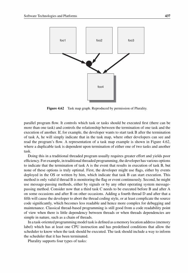
P1: OTA/XYZ P2: ABCc04 BLBK307-Bachmutsky September 2, 2010 13:18 Printer Name: Yet to Come
Software Technologies and Platforms 437
foo1 foo2 foo3
foo4
Figure 4.62 Task map graph. Reproduced by permission of Plurality.
parallel program flow. It controls which task or tasks should be executed first (there can bemore than one task) and controls the relationship between the termination of one task and theexecution of another. If, for example, the developer wants to start task B after the terminationof task A, he will simply indicate that in the task map, where other developers can see andread the program’s flow. A representation of a task map example is shown in Figure 4.62,where a duplicable task is dependent upon termination of either one of two tasks and anothertask.
Doing this in a traditional threaded program usually requires greater effort and yields poorefficiency. For example, in traditional threaded programming, the developer has various optionsto indicate that the termination of task A is the event that results in execution of task B, butnone of these options is truly optimal. First, the developer might use flags, either by eventsdeployed in the OS or written by him, which indicate that task B can start execution. Thismethod is only valid if thread B is monitoring the flag or event continuously. Second, he mightuse message-passing methods, either by signals or by any other operating system message-passing method. Consider now that a third task C needs to be executed before B and after Aon some occasions and after B on other occasions. Adding a fourth thread D and after that afifth will cause the developer to abort the thread coding style, or at least complicate the sourcecode significantly, which becomes less readable and hence more complex for debugging andmaintenance. Classical thread-based programming is still good from a code readability pointof view when there is little dependency between threads or when threads dependencies aresimple in nature, such as a chain of threads.
In a task-oriented programming model task is defined as a memory location address (memorylabel) which has at least one CPU instruction and has predefined conditions that allow thescheduler to know when the task should be executed. The task should include a way to informthe scheduler that it has been terminated.
Plurality supports four types of tasks:

P1: OTA/XYZ P2: ABCc04 BLBK307-Bachmutsky September 2, 2010 13:18 Printer Name: Yet to Come
438 System Design for Telecommunication Gateways
� Regular task.A regular task, when enabled, can only run on one core. Regular tasks can affect programcontrol flow through three types of termination tokens (see a further description of tokensbelow), therefore enabling a more complex program flow.
� Duplicate task.A duplicate task, when enabled, can be executed on more than one core. A duplicate taskhas only one type of termination token.
� Interrupt task.An interrupt task is connected to a predefined interrupt source and is enabled whenever itsmask allows and the interrupt is received. Obviously, it can only be executed on one core asa regular task. An interrupt task has three types of termination token.
� Dummy task.A dummy task is a task that is not allocated. It is meant to be used internally by the schedulerto enable more complex task conditions, especially when there are any limitations in taskdependency implementation; Plurality’s HW scheduler can have only two AND connectionsin the task dependency. For example, if tasks A, B, C, and D are all the dependencies oftask E (i.e., task A, B, C, and D must be terminated in order to allocate task E), there isa need to use a two dummy tasks in order to enable the connections: tasks A and B willenable dummy task X; and tasks C and D will enable dummy task Y; task E, therefore, willbe enabled when task X and Y are enabled.
The following are definitions of basic terms related to task scheduling:
� Instance – a single execution of a duplicable task.� Quota – the number of instances of a duplicable task available for execution when its Boolean
condition is enabled.� Task allocation – assigning a single core to execute a single task or one instance of a
duplicable task.� Task enabling – when the task has received all its enabling input tokens and is available for
allocation.� Task execution – when the task, or its instances, was allocated to the available cores of the
system.� Task termination – when the task is finished and all of its tokens have passed to the dependent
tasks.
There term token has been mentioned above a number of times. Plurality refers to tokensin the same way as in petri nets,96 where the termination of one task passes a token to thedependent task. To enable a task, its input tokens must be passed so that its Boolean enablingcondition becomes true. The conditions are usually simple, but can also be more complex. Forexample, if task X is dependent upon the termination of task Y, task Y passes a token to task Xwhen it is terminated, and task X receives a token from task Y. There are five types of Booleanenabling conditions in the Plurality’s model:
96 http://www.petrinets.info/ and http://www.petrinets.info/docs/pnstd-4.7.1.pdf.
P1: OTA/XYZ P2: ABCc04 BLBK307-Bachmutsky September 2, 2010 13:18 Printer Name: Yet to Come
Software Technologies and Platforms 439
� Empty condition. This means that the task that has the aforementioned condition will onlybe enabled after the initialization of the program. This is called a ‘pre-enabled’ condition.
� X: This means that the task that has the aforementioned condition will only be enabled whentask X is terminated.
� X & Y: This means that the task which has the aforementioned condition will only be enabledwhen both task X and Y are terminated. This is called an ‘and’ condition.
� X | Y: This means that the task that has the aforementioned condition will only be enabledwhen one of tasks X or Y is terminated. This is called an ‘or’ condition.
� X & (Y | Z): This means that the task that has the aforementioned condition will only beenabled when both task Y or task Z, and task X were terminated (similar to Figure 4.62).
A token accepted from a regular task differs from other token types. A regular task can pass(or return) a variable token. The values of the tokens are either true, false or do not care.
� False token.A false token has the value of 0 and is set to be returned by a special termination commandin the program. When task X returns a false token, only the tasks that are dependent upon thefalse token are affected. This is a default token flag if the user does not provide a differenttermination command.
� True token.A true token has the value of 1 and it is set to be returned by a special termination commandin the program. When task X returns a true token, only the tasks that are dependent uponthe true token are affected.
� Do not care token.A do not care token disregards the termination command value and affects any dependenttask. A task dependent upon a do not care token is always enabled when task X is terminated.
As indicated previously, a task’s quota is the number of instances of a duplicable task Xavailable for execution when X is enabled. Every instance has a unique instance number, oridentification. For example, let us assume that there is a need to execute seventeen instances oftask A in parallel. Let us say that task A has a quota of 17. Plurality’s scheduler will allocatethe instances of task A to the available cores while setting the instance number accordingly.The first allocation has instance number of 0 (zero), second allocation has instance number of1 (one), and so on. The quota for task X is defined in run-time by a specific function in theprogram. It is important to understand that the quota is different from the number of differentcores executing the task. When a task has a quota of X, it does not necessarily mean that itwill be executed on X different cores. The scheduler defines the number of different cores thatwill execute the task. The quota can be much bigger than the number of cores available on agiven machine and the developer can disregard the specific implementation of that machine.
A duplicable task with zero quota acts as if it is a Dummy task because it is just passingtokens to the dependent tasks. Also, for the purpose of task termination a duplicable task istreated as a single task entity, meaning that with a non-zero quota of the duplicable task X,only when all instances of task X are terminated the task will be considered to be terminatedand its token will be passed.
There might be some situations in which a token is passed to task X, but the second tokenhas not been passed for any reason. Task X just waits for the second token and cannot be

P1: OTA/XYZ P2: ABCc04 BLBK307-Bachmutsky September 2, 2010 13:18 Printer Name: Yet to Come
440 System Design for Telecommunication Gateways
Input
OutputColumn Counter True
1st Stage Butterfly1st Stage Butterfly
1st Stage Butterfly
2nd Stage Butterfly2nd Stage Butterfly
2nd Stage Butterfly
3rd Stage Butterfly3rd Stage Butterfly
3rd Stage Butterfly
Fals
e
Input
OutputColumn Counter True
1st Stage Butterfly1st Stage Butterfly
1st Stage Butterfly
2nd Stage Butterfly2nd Stage Butterfly
2nd Stage Butterfly
3rd Stage Butterfly3rd Stage Butterfly
3rd Stage Butterfly
Fals
e
Figure 4.63 Task map graph for FFT calculations. Reproduced by permission of Plurality.
enabled. In this scenario, there might be a need to clear the token passed to X, or to reset thetokens of task X. A special reset token can be connected to task X that can clear the awaitedtokens when needed; this enables task X to return to its initial state.
A slightly more complex task map diagram for Fast Fourier Transform (FFT) calculationsis shown in Figure 4.63. It was presented by Plurality at the Multicore Expo 2008.
Two simple programming examples can provide a better explanation of the task-orientedmodel:
• Vector sumThe source code is the following:/∗ Header file for all HAL specific macros ∗/#include <hal. h>
#include ‘top enums.h’#define N 10int arr[N] = {1,2,3,4,5,6,7,8,9,10};int arr1[N] = {1,2,3,4,5,6,7,8,9,10};/∗ Here we declare the following functions as tasks.So the compiler (GCC) will emit special code regarding tasks ∗/void init (void) HAL DEC TASK;void evaluate (void) HAL DEC TASK;/∗ The init task initializes the quota of task evaluate ∗/void init (void){HAL SET QUOTA(evaluate, N);}/∗ The evaluate task evaluates the add of arr[i] and arr1[i] ∗/void evaluate (void)
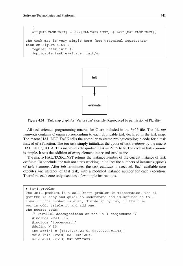
P1: OTA/XYZ P2: ABCc04 BLBK307-Bachmutsky September 2, 2010 13:18 Printer Name: Yet to Come
Software Technologies and Platforms 441
{arr[HAL TASK INST] = arr[HAL TASK INST] + arr1[HAL TASK INST];}
The task map is very simple here (see graphical representa-tion on Figure 4.64):
regular task init ()duplicable task evaluate (init/u)
init
evaluate
Figure 4.64 Task map graph for ‘Vector sum’ example. Reproduced by permission of Plurality.
All task-oriented programming macros for C are included in the hal.h file. The file topenums.h contains C enum corresponding to each duplicable task declared in the task map.
The macro HAL DEC TASK tells the compiler to create prologue/epilogue code for a taskinstead of a function. The init task simply initializes the quota of task evaluate by the macroHAL SET QUOTA. This macro sets the quota of task evaluate to N. The code in task evaluateis simple. It sets the addition of every element in arr and arr1 to arr.
The macro HAL TASK INST returns the instance number of the current instance of taskevaluate. To conclude, the task init starts working, initializes the numbers of instances (quota)of task evaluate. After init terminates, the task evaluate is executed. Each available coreexecutes one instance of that task, with a modified instance number for each execution.Therefore, each core only executes a few simple instructions.
• 3n+1 problemThe 3n+1 problem is a well-known problem in mathematics. The al-gorithm is easy and quick to understand and is defined as fol-lows: if the number is even, divide it by two; if the num-ber is odd, triple it and add one.The source code:
/∗ Parallel decomposition of the 3n+1 conjecture ∗/#include <hal. h>
#include ‘top enums.h’#define N 10int arr[N] = {451,3,14,23,51,68,72,23,91143};void init (void) HAL DEC TASK;void eval (void) HAL DEC TASK;

P1: OTA/XYZ P2: ABCc04 BLBK307-Bachmutsky September 2, 2010 13:18 Printer Name: Yet to Come
442 System Design for Telecommunication Gateways
void decide (void) HAL DEC TASK; /∗ Task initializes the quotasize of eval ∗/
void init (void) {HAL SET QUOTA(eval,N);} /∗ Task evaluates theconjecture on arr indexes ∗/
void eval (void){
if (arr [HAL TASK INST] ! = 1){if (arr [HAL TASK INST]% 2 = = 0)arr [HAL TASK INST] / = 2;else
arr [HAL TASK INST] = 3 ∗ arr [HAL TASK INST] + 1;}
}/∗ Task decides whether on not to continue execution ∗/void decide (void){
int i;for (i = 0; i < N; ++i)if (arr [i] ! = 1){HAL TASK RET TRUE;break;}}
Task map (see graphical representation on Figure 4.65):regular task init ()duplicable task eval (init/u | decide/1)regular task decide (eval)
init
evaluate
decide
/ 1
Figure 4.65 Task map graph for ‘3n + 1’ example. Reproduced by permission of Plurality.

P1: OTA/XYZ P2: ABCc04 BLBK307-Bachmutsky September 2, 2010 13:18 Printer Name: Yet to Come
Software Technologies and Platforms 443
This algorithm is a bit more complicated than the vector-adding example, but it is still simple.The program starts at init and initializes the quota for task eval. When init is terminated, taskeval is allocated and executed. When task eval is terminated, task decide is allocated andexecuted. The idea of task decide is to make a decision whether or not there is a need tocontinue to evaluate the conjecture. Every time it finds a number different from 1, it continuesthe execution. Task decide passes a true token. Task eval’s tokens are both the termination oftask init or the termination of task decide while passing a true token. Therefore, the code isexecuted in loop until all arr values are equal to one. The loop is defined explicitly in the taskmap.
As above examples show clearly, task-oriented programming in general and fine-grainedtask-oriented programming in particular require a different approach than the more conven-tional and better known programming models.
4.3.9 Multicore Performance Tuning
Any processor selection requires some amount of performance tuning. If the processor ischosen with some spare capacity in mind and processing overdesign, the tuning can be initiallylighter, but it is still needed at some point in time. This chapter uses Cavium Networks’OCTEON processors as an example for performance optimization procedures, which aresometimes generic, but in some cases hardware-specific.
Cavium Networks defined in their whitepaper ‘OCTEON Application Performance Tuning’the good basic principles for the task:
A. Set up a performance-tuning test bed.B. Reduce the number of cores to the smallest set; a single core is the best start if the design
allows it, a functional pipeline design could make it harder (see Figure 4.66, four coresare shown as a minimum set example).
C. Run a preliminary test with the application behaving as close as possible to the finalapplication, or with as close as possible an approximation or estimation of such behavior.If the actual performance is close enough to the desired performance, performance tuningwill be sufficient to close the gap. It is difficult to define the term ‘close enough’ here,because it largely depends on the design, but the usual ‘rule-of-thumb’ is performancewithin 20%–30% off target. For instance, if the required throughput is 10 Gbps and
Traffic Generator – Transmit Function
Traffic Generator – Receive Function
Minimum Set of Cores Test Setup
Multicore Processor
C C C C
X X X X
X X X X
X X X XC = On core, in use
X = Unused cores
Figure 4.66 Minimum tuning configuration. Reproduced by permission of Cavium.
P1: OTA/XYZ P2: ABCc04 BLBK307-Bachmutsky September 2, 2010 13:18 Printer Name: Yet to Come
444 System Design for Telecommunication Gateways
the intial test shows 8 Gbps, then it makes sense to tune the system for the highestperformance with the smallest set. If the performance is much worse, then the designshould be reevaluated before any performance tuning is started. For example, the OSselection has to be evaluated: it is recommended to use RTOS, Simple Executive, real-time Linux distribution or the environment similar to the Zero Overhead Linux (seeSection 4.1.1) for data plane processing.
If performance tuning is needed, then the goal is to isolate the function containingthe bottleneck. One way is to minimize a number of variables affecting performance byreplacing one or more functions with their simplified simulated implementations. For asmall number of functions this can be done function-by-function measuring performanceeach time. When the number of functions or potential bottlenecks is too large, there mightbe a need for more sophisticated search algorithms. For example, the binary tree selectionprinciple can be tried, starting with half of functions and adding or dropping half of whatis left, and so on. Cycle counters or time stamps collection can be added into the code tocalculate time and/or number of computing cycles spent between the collection points.Using one of these techniques, it should be possible to identify one or two functions withthe most severe problems; optimization should focus on these functions. This step can berepeated until the desired performance is reached.
Many development environments provide much more sophisticated tools. Usually,profiling tools can help to evaluate performance bottlenecks. Section 3.1.1.3 describes,for example, a set of tools that can be used for Sun multicore profiling. Cavium Networks(other vendors often have similar tools) provides another set of tools that can help in thetask (most are generic, but ported to be used on a particular hardware):(a) Simulator – simulates the hardware, can be useful, for example, in finding the number
of TLB exceptions or cache misses; it is good practice to make sure that the codecan run on the simulator (provides easier debugging, makes the software developmentless dependent on hardware, separates hardware problems from software problems,etc.), but in some cases the software has to be modified for that purpose (boot pro-cess, hardware initialization and status check, and many others), and in such a casethe overhead of maintaining different code base for hardware- and simulator-basedapproaches has to be considered.
(b) PCI Profiling – real-time profiling of a running application over PCI.(c) Perfzilla – a graphical interface wrapper.(d) Profile-Feedback Optimization, also called feedback-driven optimization (FDO),
which is used to guide the compiler in making optimization choices in differentparts of the program based on the profiling results. One example of such optimizationis to identify the most probable paths in branch operators based on some test cases(such as a particular ‘if’ statement is mostly true) and optimize the compilation basedon the collected information. Of course, the code will be optimized for a selected testscenario, and the performance of other test cases could be lower.
(e) Viewzilla – runs on the simulator’s output and provides profiling information.(f) Oprofile in Linux – uses the internal core counters; may be utilized to statistically find
L1 instruction and data cache misses, branch misses, unaligned memory accesses, etc.(g) Top in Linux – shows system versus user time and processes/threads binding to
specific cores, with the most important information being the percentage of each coreutilization.

P1: OTA/XYZ P2: ABCc04 BLBK307-Bachmutsky September 2, 2010 13:18 Printer Name: Yet to Come
Software Technologies and Platforms 445
(h) Time in Linux – shows amount of time spent in different parts (real time, user time,system time).
(i) Prof and Gprof in Linux – the commonly used profile utilities.(j) CPU counters, which can be programmed to count specific events, such as L2 cache
performance counters, DRAM utilization registers and many others.Usage of hardware resources has to be considered carefully. For example, Cavium
Networks’ OCTEON processor has the capability to reschedule the packet either becauseof the retagging or the need to defer processing. This is a powerful and useful feature, butit can also affect performance if not designed well. One of the potential bottlenecks can bean additional load on the POW hardware block within the processor that is responsible forthe rescheduling task (for POW capabilities, the CN68XX would be better than CN58XX,which is much better than CN38XX). An important factor may be not only the POW load,but also the number of entries that can be kept on-chip, which is relatively large, but alwayslimited. The block is very flexible and can use an external memory when the number ofentries exceeds the capabilities of the on-chip table, but access will be significantly sloweraffecting the performance, which can drop by up to 50% in terms of the number of entriesprocessed per second. Another issue is the overhead of the procedure to program thehardware, which is ok for complex processing algorithms, but can be prohibitive for verysimple packet manipulations. One more item to take into account is data locality, becausethe hardware can reschedule packet handling to a different core causing L1 cache missesand corresponding performance degradation.
Cavium Networks has created a useful checklist for the optimization tasks applicable fortheir hardware (see Figure 4.67), a similar checklist should be created for any processor.Obviously, the optimization effort should start with items with the biggest impact, followedby the medium and then the smallest result. For example, compressing data structures andadding prefetch and store preparations based on cache miss statistics would be the initialtarget for code modifications. Tighter control over thread allocation in the SMP-based OScan also bring very dramatic improvements in performance, especially in architectureswith multithreaded cores.
An important optimization task for multicore processors is to provide as much paral-lelism, as little data sharing between modules and as short critical sections as possible.Sometimes algorithms can be modified to minimize the usage of semaphores or atomicoperations; in other cases some hardware offload features can help. For example, routingprotocol optimization can benefit from some memory management, table lookup and hashcalculation acceleration capabilities in some processors.
Software architecture, especially multithreading, functional pipelining and similar fea-tures have to be reviewed. Typically, run-till-completion implementation will be moreefficient than pipelining because of the extra context or core switching in the case ofthe latter. Also, interrupt-based processing has to be compared to polling-based becauseinterrupts have a significant processing overhead. In some applications a hybrid approachcan be considered, when the interrupt is used to wake-up the processing algorithm andthen polling is applied either for a given period of time or until some pre-configuredamount of data is processed.
All data structures have to be checked for correct field alignment. Even when unalignedaccess is allowed, it can be less efficient than aligned access. The optimal alignmentis a processor-specific, and it can be on a 2-byte, 4-byte, 8-byte or even higher level

P1: OTA/XYZ P2: ABCc04 BLBK307-Bachmutsky September 2, 2010 13:18 Printer Name: Yet to Come
446 System Design for Telecommunication Gateways
Linux, Simple Exec, Both,
or Architecture H
ard
war
e A
ssis
t
Item to Check (Ordered in the same order presented in this document. Within each section, the items are ordered from easiest to hardest to implement.)
Possible Improvement (Big, Medium,
Small)
Software Architecture for High PerformancemuideMgnixednI ehcaC desailA :noitarugifnoC ehcaC 2LXcexE elpmiS
Both X Configuring the Right Amount of Packet Data buffers and WQE buffers BiggiBSO rehto ro xuniL susrev evitucexE elpmiS gnisoohCerutcetihcrA
muideMseuqinhceT gnimmargorP tnerrucnoChtoBArchitecture Pipelined versus Run-to-C giBerutcetihcrA erawtfoS noitelpmo
giBgnissecorP tekcaP rof gnildnaH tpurretnI susrev pool nevird-tnevEerutcetihcrATuning the Minimum Set of Cores
Both Compiler Choice MediummuideM)3O-( noitazimitpO relipmoChtoB
Both X Re-Configuring the Right Amount of Packet Data buffers and WQE buffers MediummuideMtnemngilA yromeMXhtoB
giBserutcurtS gnignarra-eR ,)gnikcap( noitcapmoC erutcurtS ataDhtoBgiBeziS enil-ehcaC htiw gnikroW :serutcurtS ataD egraLhtoB
muideMrehtegoT ataD nommoC puorGhtoBllamS/muideMgnillornU pooLhtoB
Both Replace memset() and memcpy() muideMdedeeN nehw Simple Exec X Use Free Pool Allocator (FPA) Memory Pools to Manage Free Buffers Small
Both X Cache Prefetch BigBoth X Prepare for Store Big
llamSegarotS lacol-eroC :daphctarcSXcexE elpmiSmuideMnoitacollA APF suonorhcnysAXcexE elpmiSllamSsdnammoC )BWD( kcaB etirW t'noDXhtoBmuideMenignE CRC erawdraHXhtoBmuideMenignE hsaH erawdraHXhtoBmuideMsremiT erawdraHXcexE elpmiSmuideMtinU )UAF( ddA dna hcteF erawdraHXcexE elpmiSmuideMsnoitarepO ddA dna hcteF suonorhcnysAXcexE elpmiS
Both X Work prefetch: Asynchronous get_work MediumllamSsnoitcurtsnI lanoitatupmoC htiw hcteferP gnivaelretnIXhtoBmuideMnoitaluclaC muskcehC PDU/PCT erawdraHXhtoBmuideMylesiW snoitcnuF esUhtoBmuideMylesiW sdleif-tiB etadpUhtoB
Both Read after Write MediumTuning Multi-core Applications (Scaling)
Both X Re-Configuring the Right Amount of Packet Data buffers and WQE buffers MediumllamSswolF etarapeS ot seulaV gaT laitinI enuTXcexE elpmiSmuideMelbissoP fi DEREDRO ot epyT gaT laitinI teSXcexE elpmiSmuideMelbissoP nehw LLUN ro DEREDRO ot epyT gaT hctiwSXcexE elpmiSllamSsnoitarepO hctiwS gaT suonorhcnysA esUXcexE elpmiSmuideMsnoigeR lacitirC eziminiMhtoBmuideMelbissoP nehw sepyT gaT CIMOTA htiw skcoL nipS ecalpeRXcexE elpmiSmuideMnoitacollA yromeM desab-anerAhtoB
Both X L2 Cache Configuration: Way-Partitioning and Cache-Block Locking MediumLinux-specific Tuning
giBeziS egaP eguH dna snoitpecxE BLTXxuniLgiBsdaerhT/sessecorP rof ytiniffA UPC esUxuniL
llamSeroC emaS eht ot stpurretnI XR tekcaP lla tceriDxuniL
Figure 4.67 Cavium Networks OCTEON performance tuning checklist. Reproduced by permission ofCavium.
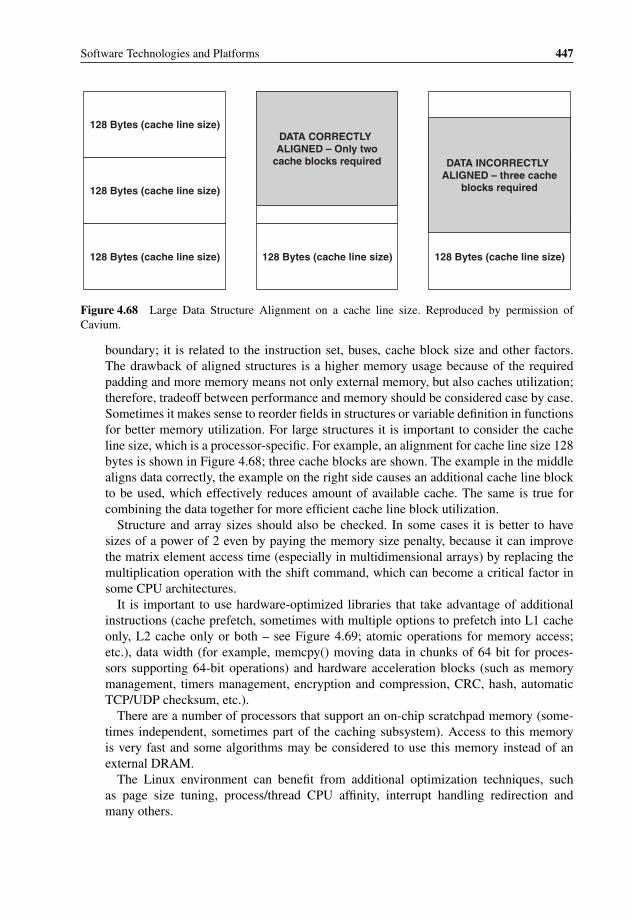
P1: OTA/XYZ P2: ABCc04 BLBK307-Bachmutsky September 2, 2010 13:18 Printer Name: Yet to Come
Software Technologies and Platforms 447
128 Bytes (cache line size)
128 Bytes (cache line size)
128 Bytes (cache line size) 128 Bytes (cache line size)
DATA CORRECTLY ALIGNED – Only two
cache blocks required
128 Bytes (cache line size)
DATA INCORRECTLY ALIGNED – three cache
blocks required
Figure 4.68 Large Data Structure Alignment on a cache line size. Reproduced by permission ofCavium.
boundary; it is related to the instruction set, buses, cache block size and other factors.The drawback of aligned structures is a higher memory usage because of the requiredpadding and more memory means not only external memory, but also caches utilization;therefore, tradeoff between performance and memory should be considered case by case.Sometimes it makes sense to reorder fields in structures or variable definition in functionsfor better memory utilization. For large structures it is important to consider the cacheline size, which is a processor-specific. For example, an alignment for cache line size 128bytes is shown in Figure 4.68; three cache blocks are shown. The example in the middlealigns data correctly, the example on the right side causes an additional cache line blockto be used, which effectively reduces amount of available cache. The same is true forcombining the data together for more efficient cache line block utilization.
Structure and array sizes should also be checked. In some cases it is better to havesizes of a power of 2 even by paying the memory size penalty, because it can improvethe matrix element access time (especially in multidimensional arrays) by replacing themultiplication operation with the shift command, which can become a critical factor insome CPU architectures.
It is important to use hardware-optimized libraries that take advantage of additionalinstructions (cache prefetch, sometimes with multiple options to prefetch into L1 cacheonly, L2 cache only or both – see Figure 4.69; atomic operations for memory access;etc.), data width (for example, memcpy() moving data in chunks of 64 bit for proces-sors supporting 64-bit operations) and hardware acceleration blocks (such as memorymanagement, timers management, encryption and compression, CRC, hash, automaticTCP/UDP checksum, etc.).
There are a number of processors that support an on-chip scratchpad memory (some-times independent, sometimes part of the caching subsystem). Access to this memoryis very fast and some algorithms may be considered to use this memory instead of anexternal DRAM.
The Linux environment can benefit from additional optimization techniques, suchas page size tuning, process/thread CPU affinity, interrupt handling redirection andmany others.
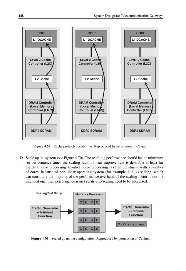
P1: OTA/XYZ P2: ABCc04 BLBK307-Bachmutsky September 2, 2010 13:18 Printer Name: Yet to Come
448 System Design for Telecommunication Gateways
L1 DCACHE
CORE
L1 DCACHE
CORE
L1 DCACHE
CORE
L2 Cache
Level-2 Cache Controller (L2C)
L2 Cache
Level-2 Cache Controller (L2C)
L2 Cache
Level-2 Cache Controller (L2C)
DRAM Controller (Local Memory
Controller (LMC))
DRAM Controller (Local Memory
Controller (LMC))
DRAM Controller (Local Memory
Controller (LMC))
DDR2 SDRAM DDR2 SDRAM DDR2 SDRAM
Figure 4.69 Cache prefetch possibilities. Reproduced by permission of Cavium.
D. Scale up the system (see Figure 4.70). The resulting performance should be the minimumset performance times the scaling factor; linear improvement is desirable at least forthe data plane processing. Control plane processing is often non-linear with a numberof cores, because of non-linear operating system (for example, Linux) scaling, whichcan constitute the majority of the performance overhead. If the scaling factor is not theintended one, then performance issues relative to scaling need to be addressed.
Traffic Generator – Transmit Function
Traffic Generator – Receive Function
Scaling Test Setup Multicore Processor
C C C C
C = On core, in use
C C C C
C C C C
C C C C
Figure 4.70 Scaled up tuning configuration. Reproduced by permission of Cavium.
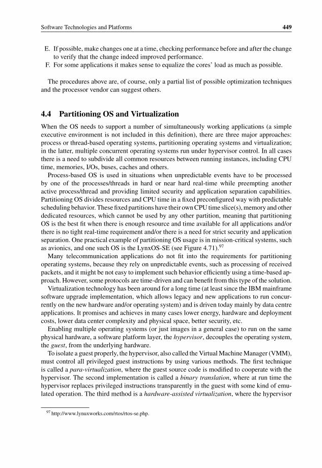
P1: OTA/XYZ P2: ABCc04 BLBK307-Bachmutsky September 2, 2010 13:18 Printer Name: Yet to Come
Software Technologies and Platforms 449
E. If possible, make changes one at a time, checking performance before and after the changeto verify that the change indeed improved performance.
F. For some applications it makes sense to equalize the cores’ load as much as possible.
The procedures above are, of course, only a partial list of possible optimization techniquesand the processor vendor can suggest others.
4.4 Partitioning OS and Virtualization
When the OS needs to support a number of simultaneously working applications (a simpleexecutive environment is not included in this definition), there are three major approaches:process or thread-based operating systems, partitioning operating systems and virtualization;in the latter, multiple concurrent operating systems run under hypervisor control. In all casesthere is a need to subdivide all common resources between running instances, including CPUtime, memories, I/Os, buses, caches and others.
Process-based OS is used in situations when unpredictable events have to be processedby one of the processes/threads in hard or near hard real-time while preempting anotheractive process/thread and providing limited security and application separation capabilities.Partitioning OS divides resources and CPU time in a fixed preconfigured way with predictablescheduling behavior. These fixed partitions have their own CPU time slice(s), memory and otherdedicated resources, which cannot be used by any other partition, meaning that partitioningOS is the best fit when there is enough resource and time available for all applications and/orthere is no tight real-time requirement and/or there is a need for strict security and applicationseparation. One practical example of partitioning OS usage is in mission-critical systems, suchas avionics, and one such OS is the LynxOS-SE (see Figure 4.71).97
Many telecommunication applications do not fit into the requirements for partitioningoperating systems, because they rely on unpredictable events, such as processing of receivedpackets, and it might be not easy to implement such behavior efficiently using a time-based ap-proach. However, some protocols are time-driven and can benefit from this type of the solution.
Virtualization technology has been around for a long time (at least since the IBM mainframesoftware upgrade implementation, which allows legacy and new applications to run concur-rently on the new hardware and/or operating system) and is driven today mainly by data centreapplications. It promises and achieves in many cases lower energy, hardware and deploymentcosts, lower data center complexity and physical space, better security, etc.
Enabling multiple operating systems (or just images in a general case) to run on the samephysical hardware, a software platform layer, the hypervisor, decouples the operating system,the guest, from the underlying hardware.
To isolate a guest properly, the hypervisor, also called the Virtual Machine Manager (VMM),must control all privileged guest instructions by using various methods. The first techniqueis called a para-virtualization, where the guest source code is modified to cooperate with thehypervisor. The second implementation is called a binary translation, where at run time thehypervisor replaces privileged instructions transparently in the guest with some kind of emu-lated operation. The third method is a hardware-assisted virtualization, where the hypervisor
97 http://www.lynuxworks.com/rtos/rtos-se.php.

P1: OTA/XYZ P2: ABCc04 BLBK307-Bachmutsky September 2, 2010 13:18 Printer Name: Yet to Come
450 System Design for Telecommunication Gateways
POSIX
Health Monitor
Cinit
Partition 0
Ada Libs
Ada App
Partition 1
JVM
Java App
Partition 2
X Windows
OpenGL
GUI App
Partition 3
POSIX
POSIX App
APEX
ARINC 653 App
Linux ABI
Linux App
Middleware
Partition N
User mode
Supervisor mode
VCTPARTITIONING KERNEL AND TCP/IP STACK
from LYNUXWORKS
CPU SUPPORT PACKAGE
BOARD SUPPORT PACKAGE
STATIC DEVICE
DRIVERSPCI DRM
DYNAMIC DEVICE
DRIVERS
MICRO-PROCESSOR
PCI CONTROLLERHARDWARE
OPTIONAL HARDWARE
PCI A
PCI B
AP
PL
ICA
TIO
N
SO
FTW
AR
ES
YS
TE
M S
OF
TW
AR
EH
AR
DW
AR
E
POSIX
Health Monitor
Cinit
Partition 0
Ada Libs
Ada App
Partition 1
JVM
Java App
Partition 2
X Windows
OpenGL
GUI App
Partition 3
POSIX
POSIX App
APEX
ARINC 653 App
Linux ABI
Linux App
Middleware
Partition N
User mode
Supervisor mode
VCTPARTITIONING KERNEL AND TCP/IP STACK
CPU SUPPORT PACKAGE
BOARD SUPPORT PACKAGE
STATIC DEVICE
DRIVERSPCI DRM
DYNAMIC DEVICE
DRIVERS
MICRO-PROCESSOR
PCI CONTROLLERHARDWARE
OPTIONAL HARDWARE
PCI A
PCI B
AP
PL
ICA
TIO
N
SO
FTW
AR
ES
YS
TE
M S
OF
TW
AR
EH
AR
DW
AR
E
Figure 4.71 Partitioning OS architecture example. Reproduced by LynuxWorks.
uses processor extensions to emulate privileged operations; sometimes such extensions enablethe performance of emulation right at the guest without even switching to the hypervisorcontext. In the two latter methods the guest would not know that there is any virtualizationlayer running in the system.
The VMM creates a virtual environment for running applications as if they were runningon physically separate hardware, while still assuming in most cases that all applications usethe same CPU instruction set, meaning that there is no need of instruction set virtualiza-tion/translation. The VMM usually virtualizes CPUs, memories and all I/O resources: externalnetwork interfaces, disks, video interface, keyboard, mouse, etc. In a simple scenario, theresources are pre-configured statically to belong to a particular VM (for example, memory isdivided into regions, and these regions are assigned to VMs; or different disk partitions areassigned to different VMs); however, some resources have to be shared (for example, the samephysical CPU core may run different VMs at different points of time with some kind of ‘fair’or priority-driven and starvation-free scheduling between them). The problem is that this typeof virtualization might not be applicable for many embedded applications that require muchmore deterministic performance and more flexible I/O usage.
In addition to virtualization of multiple running environments, the hypervisor is responsiblefor their simultaneous running, which includes their fair scheduling. This scheduling is doneindependently from the second level scheduling which can be performed by every operatingsystem internally between its threads and/or processes. Of course, both schedulings are notalways required. For example, bare-metal simple executive operating systems are single-threaded and do not have any scheduler. Also, if there are no two VMs sharing the samephysical CPU, there is no need for hypervisor-based scheduling, either. The latter is often usedin real-time systems and this mode became more viable with processors hosting a large numberof cores, where it is possible to assign the entire core or a number of cores to a particularVM. This is one of the advantages that should be taken into account when choosing between

P1: OTA/XYZ P2: ABCc04 BLBK307-Bachmutsky September 2, 2010 13:18 Printer Name: Yet to Come
Software Technologies and Platforms 451
Figure 4.72 Virtual machine latency and switch overhead. Reproduced by permission of SYSGO.
multicore and multithreading solutions (see also Section 3.5.6.1.1 and the description laterin this Chapter). However, if VM switching cannot be avoided, its overhead could becomeprohibitive. A good example of such overhead can be found in a graph from the SYSGO’swhitepaper ‘Bringing Together Real-time and Virtualization’,98 shown in Figure 4.72.
The graph provides a dependency between switching time resolution (quantum), processingoverhead and VM latency for a particular use case of only three VMs proportionally sharinga 2.4 GHz Intel Celeron core. Even with this small number of VMs, the overhead becomes10% and above, which is unacceptable for many real-time designs, with VM switching everymillisecond or slower. Little interrupt processing can be done with this type of limitation. Buteven if the quantum of more than a millisecond is acceptable, VM latency becomes too highfor some applications (as stated in the whitepaper, it ‘is roughly three orders of magnitudehigher than the jitter that typical real-time systems achieve when running on the same typeof hardware directly, that is without a virtualization layer in between’). This overhead/latencyincrease means that either an application can sustain higher latency (in many cases it can beachieved only for soft real-time as opposed to hard real-time tasks; in a soft real-time scenariothe average latency matters, but a single particular latency can be larger than average) or,otherwise, a good design should try keeping the number of VMs close to the number of coresto minimize VM switching requirements.
98 Robert Kaiser, SYSGO AG, ’Whitepaper: Bringing together real-time and virtualization’, Embedded ComputingDesign, June 2009. Online at http://www.embedded-computing.com/articles/id/?4004.

P1: OTA/XYZ P2: ABCc04 BLBK307-Bachmutsky September 2, 2010 13:18 Printer Name: Yet to Come
452 System Design for Telecommunication Gateways
When scheduling and switching still happens, the whitepaper defines the requirements fornon real-time, time-driven and event-driven VMs. For non real-time VMs there are three re-quirements: (a) distribute the available CPU time ensuring that each VM receives its designatedshare continuously; (b) all available resources have to be utilized effectively; (c) there shouldbe no condition where any VM can be starved of CPU time. The requirements for time-drivenVMs create some level of synchronization between VM scheduling and processing time insidethe VM: (a) when VM needs to run, it has been already scheduled; (b) VM needs to suspenditself before it is de-scheduled; (c) schedules of multiple time-driven VMs cannot overlap.Event-driven VMs have to be able to preempt any other VM when the corresponding eventarrives, meaning that the event processing in such VMs has to be very short so as not to affectother event-driven and time-driven VMs significantly. For all practical purposes, it is similarto interrupt processing routines. All of the requirements above and different types of VMsrequire a sophisticated scheduling mechanism, which may need to be adapted for different sys-tems. While any real-time VM has to be able to preempt non-realtime VMs, priority betweenreal-time VMs has to be configurable.
The whitepaper also describes the particular scheduler implementation of SYSGO’s PikeOS,which is an RTOS with integrated microkernel-based hypervisor. All guest VMs are groupedinto the parallel time domains, each time domain can be activated explicitly and the VM canrun only when its domain is active, which enables efficient handling of time-driven VMs.Within the time domain, every VM is assigned a priority making sure that realtime VMs get ahigher priority than non real-time ones that share a single common low priority and run whenno event-driven VM runs. Real-time VMs are scheduled based strictly on their priority withround-robin scheduling between VMs sharing the same priority. The architecture assumesthat all event-driven VMs are non-greedy leaving enough processor time to run for all nonreal-time VMs. The architecture also assumes that there are at least two time domains, thealways-active background domain and one or more foreground domains (see Figure 4.73).
The idea behind this particular architecture is to assign all time-driven VMs into the fore-ground time domains, all event-driven VMs into higher priority VMs in the backgrounddomain and all non-realtime VMs into the background domain with the same lowest priority.This solution also recommends utilizing the multicore and/or multiprocessor environment byrunning time-driven and event-driven VMs on separate sets of cores or processors in order toavoid any contention.
Assuming that the architecture of existing operating systems stays the same when introduc-ing virtualization technology, which is the current trend allowing easier migration of existingsoftware to a virtualized environment, the hypervisor creates additional level of protection, thesupervisor level. Many existing operating systems already have two levels, such as kernel anduser space in Linux. Of course, it is possible to enforce virtual machine isolation in software,but this becomes complex and slow. Processor vendors, lead by Intel and AMD and driveninitially by server and data centre markets, stepped in and introduced hardware support forthree protection layers. Lately, embedded processor vendors have also started to include partialor full virtualization support in their new generation offerings; based on the understandingthat with tight security, high availability, in-service upgradability, multi-OS implementationsfor efficient control and data plane handling, low latency and high performance requirements,embedded systems in general and telecommunication systems in particular need such supporteven more than servers. The reasons are often different from servers and data centres, wherethe main push for virtualization is to increase average processor usage by sharing the same

P1: OTA/XYZ P2: ABCc04 BLBK307-Bachmutsky September 2, 2010 13:18 Printer Name: Yet to Come
Software Technologies and Platforms 453
prio
prio
prio
dispatch
σvm(t)
prio >?
N-1
N-2
1
2
0
T0
T1
TN-1
Ready queues
Figure 4.73 Virtual machine scheduling algorithm in SYSGO PikeOS. Reproduced by permission ofSYSGO.
physical CPU between multiple VMs; however embedded reasons are no less compelling sothat the real-time embedded virtualization technology will receive the required attention.
There are many use cases for embedded virtualization, especially in telecom applications:
� Strict memory and other resources protection. For instance, Linux processes running in theuser space can be protected from each other, but kernel modules can still cause practicallyany imaginable damage. With hypervisor, all VMs can be protected strictly from others anda single point of failure moves from a relatively large kernel, where many vendors add theirown modules for performance or a particular hardware support, to a supposedly smaller,simpler and less touched hypervisor.
Strict protection also brings with it the need for security-related features and Denial-of-Service attacks detection and handling, which is much easier to enforce in a virtualizedenvironment. Some security applications, such as authentication and authorization, mightrequire strict separation in order to ensure that malicious software running potentially withinother guest operating systems cannot compromise the most security sensitive softwaremodules.
� Running concurrently management, control and data plane. This use case has becomemore and more popular with the appearance of CPUs capable of performing all tasks well,especially with multicore processors. One or more VMs, or control plane OS instances,run the control plane (for example, some mobility signaling in mobile wireless networks),one or more VMs, or management plane OS instances, run the management plane (devicemanagement, statistics collection, etc.) and one or more VMs, or data plane OS instances,

P1: OTA/XYZ P2: ABCc04 BLBK307-Bachmutsky September 2, 2010 13:18 Printer Name: Yet to Come
454 System Design for Telecommunication Gateways
run the data plane (user data forwarding and other processing). When the same OS is usedfor all three traffic types, it is possible to run the system without virtualization, but thiswould still be not the same from the security and module separation points of view.
Obviously, there is a need to separate different traffic types into at least three categories:management, control and data. In some cases it can be done by physical external portseparation, but this would be a stringent requirement for many customers that run all kindsof traffic interleaved. It is possible sometimes to separate traffic based on a virtual port(VLAN, PCIe logical channel, SPI 4.2 logical channel, etc.), but even that is not alwaysdesirable or even possible. It means that more complex traffic classification is required.There are several ways to implement classification with hypervisor integration:– Design a special dedicated VM that is responsible for ingress packet classification. In-
tegration with the hypervisor is simple, because this VM would own most or all of thephysical interfaces and the hypervisor would send all of the received packets to the VMthat in turn will be responsible for classifying the packet and sending it to the correctdata/control/management VM. There are, however, three major disadvantages: first, thereis a need for additional VM and a hypervisor can have some limitations on the number ofsupported VMs; second, there is an impact on performance in delivering a packet to theclassifier VM and then forwarding it to the target one; and third, the classifier VM canbecome a major system bottleneck.
– Modify the hypervisor code (assuming that the source code is available) by includingpacket classification functionality. This scheme solves the performance problem men-tioned above, but modification of the third party code is usually a complex task, it hassignificant maintenance implications (if the hypervisor crashes, how to prove that it is inthe original code and not in the code addition; also, all upgrades by the supplier to theoriginal code will have to be merged again and again with all required modifications)and support issues (after the modification you might be on your own from the third partysupport point of view). It is important to repeat here that while the hypervisor bringsadditional security to applications by means of VM fault isolation (one VM failure, evenin the OS kernel, does not affect other VMs), the hypervisor itself becomes a single pointof failure and its crash can bring down the entire system. In some implementations HWsupports ring 0 or supervisor mode and the crash of the module in ring 0 might not affectother applications, depending on the type of failure. In such an environment the state-less hypervisor running in ring 0 can be restarted with minimal impact, but the systemshould trust the hypervisor not to corrupt the memory of any VM. Adding any code tothe hypervisor increases the probability of the crash, because of a larger code and morecomplex processing path plus relatively limited debugging of the modified module andthe hypervisor in general as compared to the original code which is well-tested by thehypervisor vendor and indirectly by its customers.
– The capability to add a user-defined library to the hypervisor with a well-known API,which can help to avoid modification and even recompiling of the original code; thiscan work even when there is no source code available for the hypervisor. This methodsolves many of the hypervisor modification problems discussed above, but can add asmall overhead because of an additional API. The main problem is that such well-knownAPI does not exist today. Besides, there is a need to standardize such API and somepotential forums for standardization are the SCOPE Alliance (more ATCA oriented)

P1: OTA/XYZ P2: ABCc04 BLBK307-Bachmutsky September 2, 2010 13:18 Printer Name: Yet to Come
Software Technologies and Platforms 455
or the MultiCore Association (more multicore oriented, but has a virtualization projectongoing).
– Classification can be performed before the hypervisor. It can be done using external box,blade or chip, making sure that the packet arrives through a VM-specific interface withthe association configured statically. Alternatively, the same task can be performed by theon-chip pre-classifier hardware block delivering a packet directly to the VM’s buffers andqueues (can be viewed as a pre-configured internal interface) bypassing the hypervisor.This type of solution is already available from some multicore processors, includingCavium Networks, NetLogic, Sun and others (for more information about hardwareclassification see Sections 3.5.4 and 3.5.6).
� Support for multiple concurrent instances of the same application. The usual way to imple-ment this functionality is to run these instances as separate threads or processes. However,as has been discussed above, multiple threads or even processes do not provide enoughseparation and cannot guarantee that one instance failure will not affect other instances.Separate VMs, each running its own instance of operating system, could provide a higherlevel of resiliency, assuming that the memory size is not the system bottleneck, becausemultiple VMs require more memory than multiple processes. For many systems the sep-aration can be critical and sometimes can even simplify the architecture. For example, asdescribed in Section 4.3.5, if the architecture is based on twenty instances, each supporting50 000 subscribers, it is inherently more reliable than a single instance supporting the sametotal number of 1 million subscribers, because every instance would behave differently,receiving different events and running with a different timing, meaning that the probabilityof multiple instances to fail simultaneously is lower.
Multiple instances of the same application could be also driven by whole system virtual-ization, a term known in the mobile telecommunication industry as Mobile Virtual NetworkOperators (MVNO). In this business model the hardware is owned by one physical operatorthat resells the excess processing capacity to other, usually smaller, operators. The best wayto deploy this solution is through separate VMs for every MVNO.
� Separation between platform and application layers, as presented in Section 4.3.6, makingtheir development, debugging and support mostly independent. This can become a criticalpoint when the architectures are different, when suppliers are different and a significantintegration is required. On the other hand, this separation can affect performance, because itrequires passing context and/or data through the VM boundaries. When this communicationis provided by the hardware acceleration block, performance might be less of an issue.
� Legacy SW support on a new HW. This use case is based on the assumption that the virtu-alization layer is capable of emulating the physical HW, which enables performing an oldHW emulation on a new HW platform without the need to modify any existing applica-tions. However, HW emulation in a commercial off-the-shelf hypervisor can be availablefor a well-known CPU, but is practically impossible for many other HW components whichare often product-specific. Therefore, there is a need to introduce a hypervisor extensionmodule that can be programmed, for example, by the board manufacturer or system inte-grator to provide the required emulation, which brings us back to the issue of hypervisormodification as discussed above. Also, as Paul Fischer from TenAsys Corporation statedcorrectly in his article ‘Virtualization for Embedded x86‘ in the Embedded Systems Designmagazine’s August 2008 issue, the concept of para-virtualization of the hypervisor requiresnew tools for development and debugging that do not exist today. Similar to other cases

P1: OTA/XYZ P2: ABCc04 BLBK307-Bachmutsky September 2, 2010 13:18 Printer Name: Yet to Come
456 System Design for Telecommunication Gateways
of use of the hypervisor modification, it is better to have a well-known API with a plug-inpara-virtualization module than to modify the original hypervisor code.
Another case of use for legacy software support is when there is a need to run a legacysingle-threaded application that relies on dedicated available resources, which is moredifficult to achieve using regular multithreaded or multiprocessing software architecture.This case can enable easier transition from singlecore to multicore CPUs.
� High Availability. This use case can be considered when the probability for HW failures islow or the system cost cannot justify creating redundant hardware resources. Virtualizationcan enable creating redundant virtual resources and standby VMs to protect against SWfailures, which represent the majority of system failures.
� In-service SW upgrade or downgrade. It is very efficient to load new SW as a separateVM and switch the traffic to it when necessary. More complex upgrade policies can also beapplied here. For example, the policy can be to not accept any new connection in the oldSW, forcing all new connections/subscribers to be processed in the newly created VM; allexisting connections/subscribers would be handled by the old VM, which will be destroyedautomatically when it does not have any connections/subscribers or after a pre-definedtimeout. Sometimes the new SW creates system or network instability requiring automaticor manual rollback to the previous version of SW (downgrade scenario). Similar to theupgrade case, it is a much easier procedure with VMs.
� Running different and/or multiple OSs.This is a common case when data and con-trol/management planes are running using different OSs, but this use case has alreadybeen described above. Sometimes, however, there are particular reasons why an applica-tion is developed using a specific OS or, for example, a specific Linux distribution. It canbe because of some software or hardware compatibility issues, legacy software issues, asupported feature set or an API. Another potential scenario is manycore CPUs when thenumber of cores is so high that a single OS image is not efficient enough to take advantageof all cores. Either OS has to be modified to scale better, or alternatively the processing canbe split (into functional pipelines, or based on subscribers, sessions, destinations, etc.) intomultiple separate OS images, each running on its own subset of cores. Similar to the first usecase, the image load balancing can be performed using classification either by a dedicatedVM, a hypervisor or a pre-classifier.
� Isolation of the code with special intellectual property protection needs, such as per-core,GPL or other open-source licenses. For example, running third party software on all availablecores with a per-core license might be prohibitively expensive and it would make sense torun a separate VM with integrated third party licensed software on a subset of cores, whilethe other VMs would not include this particular software. A GPL license might require thepublication of the entire source code in some scenarios, which can be avoided by inclusion ina particular VM of only the interfacing module with published APIs, while the value-addedfunctionality can run in another VM without the need to publish its source code.
� Support for multiple protocols and/or neighbor device types concurrently. Such support canbe performed either by a single module with many ‘if . . . then . . . else’, or alternatively byseparate VMs for each protocol version or a neighbor type. For example, there could be oneVM that supports version 1.5 of the protocol with another VM supporting version 2.0; orone VM can support neighbors from supplier A and another VM supports all of the othervendors. The disadvantage in using multiple VMs for this functionality is that it requiresmore memory caused by a significant code and data replication, but a careful VM functional

P1: OTA/XYZ P2: ABCc04 BLBK307-Bachmutsky September 2, 2010 13:18 Printer Name: Yet to Come
Software Technologies and Platforms 457
split can minimize the impact. The advantage is that any new protocol version or neighbortype addition does not require modification of current SW, making the system significantlymore stable; related to stability is the time-to-market parameter, when a new capability hasto be released quickly with limited testing and no time for comprehensive system testingwith all of the possible permutations of options, versions, features and interoperabilityrequirements.
� Adding a new feature. This use case is a generalization of the previous one. When a newfeature is developed and deployed, it can be done in a separate VM. A huge advantage isthat such a VM is usually relatively small, easier to debug and maintain, including upgrades.The disadvantage is potentially lower performance because of an additional communicationbetween VMs; therefore, it is recommended for features that do not require extensivecommunication, or when the new feature involves the processing of a relatively small portionof the entire traffic, or when the inter-VM communication is being accelerated by hardware.For example, if a new protocol is relevant for only 5% of the traffic, the overhead foradditional communication between VMs might be not critical, but it depends, of course, onevery particular situation and the decision has to be made by software and system architectson a per-project basis.
� Running a legacy AMP code on SMP systems. This use case is the most applicable for dataplane processing applications that are written frequently for AMP systems because of itsefficiency. The AMP on SMP system means that the resources (memory, interfaces, offloadengines, etc.) are somehow partitioned between multiple AMP processors (or sets of coresin a multicore CPU scenario). This is especially important in tasks where deterministicbehavior and/or performance are much more important than a fair use of common resources.It is natural to use virtualization techniques for such a resource partitioning task; it canhelp to avoid high latency in accessing the shared resource (imagine two modules tryingto send a packet through the same physical port; one of them will have to wait, until theother finishes its transmit cycle). Some implementations (for example, those that are basedon Intel Virtualization Technology (VT)) use on-chip HW capabilities; others do not haveany HW support, and the entire implementation is done in the hypervisor; while anothergroup of implementations has some HW support with the rest of functionality done in SW.To enable improvement of real-time performance, some virtualization technologies allowdirect exclusive HW access from a particular VM bypassing the HW emulation layer.
The virtualization brings some hardware, software and system requirements for real-timeembedded usage, most important ones are being summarized below:
� Hardware requirements.– Complete VM isolation for memory, caches, queues, buffer pools and other optionally
shared on- or off-chip resources. At the same time, there is a need for a shared resourcevirtualization, including shared hardware offload engines and other blocks.
– Preferrably an additional hypervisor prioritization level, sometimes called ring 0.– Lower than 5% (lower than 2% is a desirable target) of the performance overhead compared
to a similar configuration without the hypervisor. It is difficult to achieve this level ofperformance without extensive hardware support.
– There is a need for core virtualization in processors with a small number of physical cores(hardware threads are not counted here); that need becomes less and less critical with a

P1: OTA/XYZ P2: ABCc04 BLBK307-Bachmutsky September 2, 2010 13:18 Printer Name: Yet to Come
458 System Design for Telecommunication Gateways
growing number of cores. For example, in multicore chips with sixteen and more coresthis requirement is not very strong, because each core represents at most 6% of the entireprocessing capacity in the Cavium Networks OCTEON Plus family with sixteen cores,only slightly more than 3% in the Cavium Networks CN68XX family with thirty-twocores, about 1.5% in the sixty-four-core Tilera processor, and even lower than that, whenthere are 100 cores and more. In all of these processors the potential benefit of core sharingmight not justify an additional hypervisor and system complexity.
– A need for the I/O virtualization with channel mapping and throughput enforcement. Itcan be using VLANs for Ethernet, subchannels for SPI3, SPI4, or the latest PCI Express,and proprietary extensions for Broadcom and Fulcrum Ethernet ports. The minimumguaranteed throughput has to be available to any channel when needed. This requirementincludes DMA virtualization, because in most architectures the number of available DMAchannels can be smaller than a number of VMs in the system.
� VM fault detection, VM load and unload capabilities.To ensure fault detection, systems may include periodic watchdog timers to detect runawayVMs, keepalive and other health monitoring mechanisms, memory regions protection andaccess violation detection, central hardware status monitoring and more. The functionalitycan be a part of the hypervisor or a special trusted ‘master’ VM.
� Efficient inter-VM communication.In many telecommunication systems there is a need for efficient communication betweenVMs, even when the system is architectured for complete protection. A classic example iscommunication between control and data planes, when the control plane has to programsome databases, such as lookup tables or policies, in the data plane. The management planeVM also needs some communication with other parts of the system. In some cases VMsare independent, but they use a common configuration and/or data sets for their workload,which potentially requires shared access rights management, especially when one of VMscan also update the shared data. Another use case is the notification of changes in the requiredcapacities or hardware resources for efficient system power and hardware management.
There are a number of ways to implement inter-VM communication. One possibilityis to establish a direct link between a pair of communicating VMs, which can be done,for example, either through shared memory accessible only to a particular VM pairing, orthrough a physical or logical link between VMs not accessible to others, or through a dedi-cated hardware-based mailbox. Another option is to communicate using the hypervisor as amediator or a broker. Communication between VMs can be also point-to-multipoint whenthe exact destination is unknown or the communication is targeted to more than a single VM.
In every scenario it is important to ensure that any corrupted information going throughthe communication channel can be detected and cannot be propagated to a peer or a commu-nication broker. In some cases the messages are protected by some kind of checksum/CRCor even encrypted to hide the information from the undesired ‘eyes’, but this method protectsonly against occasional corruption after the information is created. Sometimes, the problemis in the malfunctioning information source that creates an incorrect message or copieswrong or corrupted information from its memory, meaning that the receiver’s or broker’smessage parser and interpreter have to be resilient against any potential information incon-sistencies, such as wrong field alignments, wrong lengths, wrong values, etc. If strict checksare implemented in the software, which is how it is done today, the per-message overheadbecomes very high and may affect the system performance characteristics. This is the main
P1: OTA/XYZ P2: ABCc04 BLBK307-Bachmutsky September 2, 2010 13:18 Printer Name: Yet to Come
Software Technologies and Platforms 459
reason why at least during the deployment in the field many of these checks are turnedoff, causing additional risk of the snow ball effect of secondary failures. Hardware-basedvalidation would ease the problem. While the same issue also exists for inter-thread andinter-process communications, one of the main reasons for going with VMs is its additionalsecurity and separation; therefore, the receiver protection should be one of very importantpriorities for inter-VM messaging design.
� Dynamic load balancing of VMs and hardware resources.As described above, there is a need for some kind of a workload distribution between VMs.One of the simple methods is to map physical interfaces to particular VMs and assign jobsbased on this mapping. This principle is not always applicable, because in many networksdifferent types of traffic, such as control and data plane, can come over the same physicalor even logical port. Also, with multiple data plane instances, the traffic type does notprovide the entire information for an efficient load balancing decision. This load balancingwould be performed by either the ‘master’ VM, the hypervisor, external device or hardwarepre-classifier.
There is also a need in some systems to change hardware resource allocation while servingthe live traffic. For example, the distribution of processing power (cores) between the dataand control plane in mobile networks is very time-of-the-day dependent and changes a fewtimes a day (people wake up, go to work, work, go home, at home) as well as a few timesa week (working days, weekends, holidays). If the product is designed for the worst casescenario, it would need to include the maximum possible processing capacity for the controlplane and the maximum processing capacity for the data plane, which increases the totalcost. Instead, a better way is to re-assign some unused cores between the control and dataplane as needed, assuming that it can be done dynamically without a system or even VMrestart. Of course, there is a need to support this feature not only in the hypervisor, but alsoin every operating system that is involved.
4.4.1 Commercial and Open Source Embedded Hypervisor Offerings
Unfortunately, there are few real-time embedded hypervisors that are available commerciallyand many that exist are limited either in their applicability to a wide range of real-timeembedded telecommunication systems, or processor architectures, or supported operatingsystems (there is a good list of all available solutions and their comparison on Wikipedia99 ).Popular non-embedded hypervisors, such as VMware and KVM, are skipped here, because theyare better known and because in their current form they are not optimal for high-performancereal-time embedded networking products, or at least not for their hard real-time parts; theterm real-time means here a highly available system requiring a level of tens of millisecondsguaranteed response, and server-like products are excluded from the analysis, even when usedin the telecommunication industry; this does not mean, of course, that these products cannot beintegrated into a high-performance solution and a particular project could benefit from someof these technologies even in the short term. In addition to PikeOS from SYSGO describedabove, some existing hypervisor technologies include the following:
99 http://en.wikipedia.org/wiki/Comparison_of_platform_virtual_machines.

P1: OTA/XYZ P2: ABCc04 BLBK307-Bachmutsky September 2, 2010 13:18 Printer Name: Yet to Come
460 System Design for Telecommunication Gateways
� Green Hills Software’s Padded Cell secured hypervisor software100 supports x86 andPowerPC architectures and can host INTEGRITY RTOS, Linux, Windows and Solaris(the last two run with Padded Cell only on x86). Relying on the secured INTEGRITYSeparation Kernel environment, it can co-exist with other critical applications as has beenproven in multiple mission-critical avionics deployments.
The Padded Cell software runs as an additional layer to run guest operating systems asusermode applications under the INTEGRITY OS, making sure that these guest OSs andtheir hosted applications cannot cause any harm outside of these OSs. Security is basedon the strict partitioning of resources with a fixed allocation of CPU, memory and othershared resources between multiple partitions, which can become a significant restriction forsome designs as with any partitioning OS. It includes the tight monitoring of the networkingactivity of every guest OS. One potentially useful feature is the support of Linux binaries,enabling Linux applications to run in the system without a Linux overhead.
� LynxOS-based virtualization from LynuxWorks,101 which supports x86 processors runningLynxOS, Windows and Linux guest OSs and which has similarities to INTEGRITY, de-scribed above. Even its most secured deployments are similar and include military andavionics applications.
� L4 line of microkernels. This microkernel family was developed initially by Jochen Liedtkeand extended by many other projects, including L4Ka::Hazelnut, Fiasco, L4Ka::Pistachio,NICTA::L4-embedded, OKL4 and is still under development by Codezero and others.102
For example, OKL4 had paravirtualized Linux, SymbianOS, Google’s Android, Microsoft’sWindows and it supports x86, ARM and MIPS processors with a compact memory footprintof below 64 KB (at least, for ARM processors) and fewer than 10 K lines of code. Thelist suggests that the main focus of this development is more on mobile terminals thaninfrastructure-targeted real-time systems.
� Trango hypervisor, which started as a generic embedded virtualization solution, but was lateracquired by VMware, the largest commercial virtualization solution provider for serversand data centre applications, and converted into a Mobile Virtualization Platform for mobileterminals. As of the time of writing, it is not intended for telecommunication infrastructuresystems which is unfortunate, because it has a great deal of potential to become a leader inthis field, especially with the backing of such an experienced company as VMware.
� XtratuM open-source low-overhead and small-size hypervisor103 distributed under GPL li-cense and developed by the Universidad Politecnica de Valencia in Spain with contributionsfrom Lanzhou University in China. It is based on a fixed cyclic scheduler with all parti-tions executed in the processor’s user mode with no inter-partition memory sharing andintegrated inter-partition communication channels, deterministic hypervisor system calls,efficient context switching between partitions, virtual machine health monitoring supportand basic shared hardware resource virtualization. It supports x86 and SPARCv8 processorarchitectures with paravirtualized Linux and two RTOSs, PartiKle and RTEMS, supported.The Xtratum hypervisor has been selected by the European Space Agency for the SecurelyPartitioning Spacecraft Computing Resources project. Based on the supported processors
100 http://www.ghs.com/products/rtos/integrity_pc.html.101 http:// www.lynuxworks.com.102 http://en.wikipedia.org/wiki/OKL4.103 http://www.xtratum.org/.

P1: OTA/XYZ P2: ABCc04 BLBK307-Bachmutsky September 2, 2010 13:18 Printer Name: Yet to Come
Software Technologies and Platforms 461
and OSs, it looks like the XtratuM is not intended to be used in telecommunication infras-tructure systems.
� RTS Real-Time hypervisor from Real Time Systems104 targets multicore processors andhas hard real-time performance, direct hardware access using standard drivers, VM memoryseparation, configurable boot sequence and independent guest OS restart, configurable usershared memory, TCP/IP based virtual network driver for inter-VM communication and more.It supports Microsoft Windows, Linux, QNX, VxWorks, On Time RTOS-32, Microware OS-9 and Pharlap ETS operating systems. An encouraging development was the announcementin March 2009 of a joint effort with Radisys to integrate the hypervisor with Radisys systems,potentially bringing the technology to the mainstream of telecommunication infrastructureproducts. However, its huge limitation is the support of x86 and Atom processors only, whichis unfortunate, because its exposure could be much larger with support for the PowerPC,ARM and MIPS based processors which are widely used in the industry.
� Xen open-source hypervisor. This is maintained by Citrix Systems and was targeted initiallyat the enterprise environment. However, relatively recently it has been ported to ARM (theporting project is lead by Samsung) and PowerPC architectures. Its size has also been thefocus with the ARM-based code size being about 2 MB. Also, Xen relies on a specialprivileged complete Linux-based domain, dom0, to provide device drivers, which requiresmore than 10 MB of additional memory footprint. For some embedded systems it canbecome a show stopper, others (especially high-end ones) are less sensitive to size by itself,but based on the principle that stability is proportional to size, it is still large. At this pointin time, it is difficult to call Xen a real-time hypervisor and its inter-VM communication isnot the highest performer. However, work on making Xen able to serve the real-time worldhas only just started and the next ports will address these issues.
� Sun Logical Domains virtualization.UltraSPARC T1, T2 and T2 Plus processors offer a multithreaded hypervisor. Multithreadingis crucial, since the hypervisor interacts directly with the underlying chip-multithreadedprocessor. Also, the strength of Sun’s approach is that all of the layers of the architectureare fully multithreaded, from the processor and the hypervisor up through the applications,including fully multithreaded networking and the Solaris ZFS file system.
Supported in all Sun products utilizing CMT technology, Sun Logical Domains providefully virtual machines that run an independent operating system instance and contain virtu-alized CPU, memory, storage, console and cryptographic devices. Within the Sun LogicalDomains architecture, operating systems such as the Solaris 10 OS or Linux communicatethrough the hypervisor, which provides a stable, idealized and virtualizable representationof the underlying hardware to the operating system in each Logical Domain. Each Logi-cal Domain is completely isolated with the maximum number of virtual machines usuallymatching a total number of hardware threads. For example, the Sun SPARC EnterpriseT5220 server with a single 64-threaded UltraSPARC T2 processor supports up to sixty-fourlogical domains and each individual logical domain can run a unique OS instance. Whenrunning on Solaris 10 OS, Logical Domains can also host Solaris Containers to capture theisolation, flexibility and manageability features of both technologies.
The Logical Domains architecture includes underlying server hardware, hypervisorfirmware, virtualized devices and guest, control and service domains. The hypervisor
104 http://www.real-time-systems.com/real-time_hypervisor.

P1: OTA/XYZ P2: ABCc04 BLBK307-Bachmutsky September 2, 2010 13:18 Printer Name: Yet to Come
462 System Design for Telecommunication Gateways
Virtual Ethernet
Bridge
UserApplication
User Application
User Application
User Application
UserApplication
User Application
User Application
User Application
User Application
Virtual Ethernet
Bridge Device Driver
Virtual Ethernet DriverVirtual Ethernet Driver Virtual Ethernet Driver
Service DomainLogical Domain 3Logical Domain 2Logical Domain 1
Virtual Network 2
Virtual Network 1
Hypervisor
I/O Bridge
SharedNetwork Interface
Figure 4.74 Sun architecture for shared network interface virtualization. Reproduced by permissionof © 2009 Sun Microsystems, Inc.
firmware provides an interface between each hosted operating system and the server hard-ware. An operating system instance controlled and supported by the hypervisor is calleda guest domain. Communication to the hypervisor, hardware platform and other domainsfor creation and control of guest domains is handled by the control domain. Guest domainsare granted virtual device access via a service domain which controls both the system andhypervisor and also assigns I/O.
To support virtualized networking, Logical Domains implement a virtual Layer 2 switch,vswitch, connecting all guest domains with a many-to-many relationship: each guest domaincan be connected to multiple vswitches and multiple guest domains can be connected tothe same vswitch. Vswitches can either be associated with a real physical network portor they may exist without an associated port, in which case the vswitch provides onlycommunications between domains within the same system (see Figure 4.74). Each guestdomain believes that it owns the entire NIC and the bandwidth it provides, yet in practiceonly a portion of the total bandwidth is allotted to the domain. Dedicated bandwidth can bemade available by tying a vswitch device to a dedicated physical port.
Solaris Containers include important technologies that work together with the fair-sharescheduler:– SolarisTM Zones Partitioning Technology.
The Solaris 10 OS provides a partitioning technology called Solaris Zones that can beused to create an isolated and secure environment for running applications. A zone is avirtualized operating system environment created within a single instance of the SolarisOS. Zones can be used to isolate applications and processes from the rest of the system.This isolation helps enhance security and reliability since processes in one zone areprevented from interfering with processes running in another zone.
– Resource Management.Resource management tools provided with the Solaris OS help allocate resources suchas CPUs to specific applications. CPUs in a multiprocessor system (or threads in the

P1: OTA/XYZ P2: ABCc04 BLBK307-Bachmutsky September 2, 2010 13:18 Printer Name: Yet to Come
Software Technologies and Platforms 463
UltraSPARC T2 and UltraSPARC T2 Plus processors) can be partitioned logically intoprocessor sets and bound to a resource pool, which in turn can be assigned to a Solaris OSzone. Resource pools provide the capability to separate workloads so that consumption ofCPU resources does not overlap and also provide a persistent configuration mechanismfor processor sets and scheduling class assignment. In addition, the dynamic featuresof resource pools enable the adjustment of system resources in response to changingworkload demands.While Sun has good and well-suited virtualization architecture and technology, its limited
OS and processors coverage will make it merely a niche solution if not addressed quickly.� VirtualLogix hypervisor105 is another promising commercial hypervisor. It supports x86,
Atom, ARM, PowerPC and even Texas Instruments’ multicore DSP processors, with oper-ating systems that include Linux, Windows, C5, VxWorks, Nucleus, DSP/BIOS, Google’sAndroid and bare-metal proprietary OSs.
The major concern with VirtualLogix is not its solution but the company’s stability asa small start-up and its potential refocusing on some non-infrastructure markets, such asmobile phones, similar to Trango after the VMware acquisition (as of the time of writing,they claim that they will continue coverage for all markets, including mobile terminals,infrastructure and embedded systems).
� Wind River hypervisor.106 What makes this solution promising are its roots in hard real-time embedded systems and support for two of the very popular operating systems in thetelecommunications field, Wind River Linux PNE/LE and VxWorks RTOS, with additionalsupport for the bare-metal simple executive style of OS for data plane processing. It has highperformance, a small footprint, determinism, low latency and high reliability. It has beenported to x86 and PowerPC processors and it has potential to be ported efficiently to ARMand MIPS based multicore CPUs. Wind River hypervisor can be configured to use all of itsfeatures, including core virtualization, or can be scaled down to be a minimal ‘supervisorin order’ to provide improved protection, reliability and scalability in a supervised AMP(sAMP) configuration (one VM per core).
To summarize the situation as of the time of writing, there are many hypervisors, but fewcan be used for high-end telecommunication gateway applications and those that exist havemany limitations in terms of size, hardware support, guest OSs, scalability, communicationand performance overhead. In addition, all of the solutions are proprietary, with complexportability issues if there is a need to move from one virtualization solution to another. Itis a real challenge for system architects, because early processor selection could reduce thenumber of choices drastically for virtualization, and vice versa.
4.4.2 Hypervisor Benchmarking
The number of hypervisor offerings for some processor architectures creates the problem offair comparison and selection. This is precisely the problem that the Embedded MicroprocessorBenchmark Consortium (EEMBC) is trying to solve. Markus Levy, the founder and president
105 http://www.virtuallogix.com/.106 http://www.windriver.com/products/hypervisor/.

P1: OTA/XYZ P2: ABCc04 BLBK307-Bachmutsky September 2, 2010 13:18 Printer Name: Yet to Come
464 System Design for Telecommunication Gateways
of EEMBC and the president of Multicore Association (MCA) has outlined the major targetsfor such benchmarking in his article [Virtualization-Benchmarking-EEMBC]:
� Any required system calls must be made through the hypervisor’s API.� Benchmark kernels have to be implemented in isolated VMs with a scheduler switching
between VMs at least every 10 msec to measure the impact of the VM switching time.� The CPU must have at least two privileged modes of operation to provide isolation of VMs
from the hypervisor.� The CPU must have MMU or MPU to enable VM-to-VM isolation (benchmarking is not
for the CPU in this case, it is for the hypervisor).� The benchmark target is to compare the hypervisor overhead while running on the same
processors and in the same software environment. The assessment should be reasonableacross a wide range of applications.
� Three scenarios are specified:– Each workload runs sequentially N times without the hypervisor and the total execution
time and the power consumption are measured.– Each workload runs sequentially N times in one VM with the hypervisor and the total
execution time and the power consumption are measured.– Three separate VMs running the workloads N times, and the total execution time and the
power consumption are measured.� The benchmark is calculated from the difference between Scenario 1 and 2 for a single VM
and Scenario 1 and 3 for multiple VMs.� It is more difficult and sometimes even impossible to compare hypervisors running on dif-
ferent HW and different SW implementations. This raises again the topic of interchangeablehypervisors without any other SW modifications, meaning standardized hypervisor APIs,which do not exist today, but which will happen eventually.
� The Current benchmark does not address issues specific for multicore devices; therefore,it does not measure communication between cores in the same CPU as a separate item. Ifa hypervisor can make use of multiple cores, the overall performance of the hypervisor isanalysed with no particular attention being given to the fact it is using multiple cores.
The benchmark also defines that all tested hypervisors have to be available commerciallyand downloadable versions as opposed to special builds are highly optimized for a particularbenchmarking test.
The future of the hypervisor benchmarking is very good, it definitely needs to cover multicorechips and the industry will benefit greatly from this benchmark.

P1: OTA/XYZ P2: ABCref BLBK307-Bachmutsky August 19, 2010 14:33 Printer Name: Yet to Come
References
[Axel K.Kloth] Axel K. Kloth: Advanced Router Architectures, CRC, 2005, ISBN 0849335507.[Concurrency-Pillars] Herb Sutter, ‘The Pillars of Concurrency’, Dr. Dobbs magazine, July 02, 2007.[DPI-XML-IBM] S. Letz, R. Seiffert, J. van Lunteren, and P. Herrmann, ‘System Architecture for XML Offload to
a Cell Processor-Based Workstation’, Proceedings of the XML 2005 Conference (XML2005), Atlanta, GA, USA,November 2005.
[FPGA-ASIC] Ian Kuon, Jonathan Rose: Quantifying and Exploring the Gap Between FPGAs and ASICs, Springer,2009, ISBN 1441907386.
[FPGA-MATLAB] P. Banerjee, et al., ‘Making Area-Performance Tradeoffs at the High Level Using the AccelFPGACompiler for FPGAs,’ In Proceedings of International Symposium on Field Programmable Gate Arrays, pp. 237,2003. http://www.portal.acm.org/citation.cfm?id=611817.611854.
[FPGA-MediaBench] Chunho Lee, Miodrag Potkonjak, William H. Mangione-Smith, ‘MediaBench: A Toolfor Evaluating and Synthesizing Multimedia and Communications Systems’. http://www.citeseerx.ist.psu.edu/viewdoc/summary?doi=10.1.1.12.2091.
[FPGA-RAW] Babb, J.; Frank, M.; Lee, V.; Waingold, E.; Barua, R.; Taylor, M.; Kim, J.; Devabhaktuni, S.; Agarwal,A. FPGAs for Custom Computing Machines, 1997. Proceedings., The 5th Annual IEEE Symposium, 16–18 Apr1997, pp. 134–143.
[GODSON] Weiwu Hu, Jian Wang, Xiang Gao, Yunji Chen, Qi Liu, GODSON-3: A Scalable Multicore RISCProcessor with X86 Emulation, IEEE Micro, 29(2), 2009, pp. 17–29.
[GPU-Database] Andrea Di Blas, Tim Kaldewey, ‘ Data Monster – Why graphics processors will transformdatabase processing’, IEEE Spectrum, Volume 46, Number 9. Also, online at http://www.spectrum.ieee.org/computing/software/data-monster.
[GPU-Owens] J. D. Owens, M. Houston, D. Luebke, S. Green, J. E. Stone, J. C. Phillips, ‘GPU Computing’,Proceedings of the IEEE, Vol. 96, no. 5, pp. 879–899, May 2008, ©2008 IEEE.
[GPU-CPU-Owens] John D. Owens, David Luebke, Naga Govindaraju, Mark Harris, Jens Kruger, Aaron E. Lefohn,and Tim Purcell. ‘A Survey of General-Purpose Computation on Graphics Hardware.’ Computer Graphics Forum,26(1): 80-113 (March 2007).
[GPU-Seiler] ACM Transactions on Graphics, Vol. 27, No. 3, Article 18, August 2008.[Heterogeneous-Kumar] Rakesh Kumar, Dean M. Tullsen, Parthasarathy Ranganathan, Norman P. Jouppi, Keith
I. Farkas, ‘Single-ISA Heterogeneous Multi-Core Architectures for Multithreaded Workload Performance‘, InProceedings of the 31st International Symposium on Computer Architecture, June, 2004.
[HighAvailability-Iniewski] Krzysztof Iniewski, Carl McCrosky, Daniel Minoli, ‘Network Infrastructure andArchitecture: Designing High-Availability Networks’, Wiley, 2008, ISBN 978-0-471-74906-6.
[HighAvailability-Bachmutsky] Marcos Katz (Editor), Frank Fitzek (Editor), ‘WiMAX Evolution: EmergingTechnologies and Applications’, Wiley, 2009, ISBN 978-0-470-69680-4, pp 163–182: Alexander Bachmutsky,‘ASN-GW High Availability through Cooperative Networking in Mobile WiMAX Deployments’.
[Middleware-Boot-Hallinan] Christopher Hallinan, ‘Embedded Linux Primer: A Practical Real-World Ap-proach’, Prentice Hall, 2006, ISBN 0131679848. Also, online http://www.whitepapers.zdnet.com/abstract.aspx?kw=bootloader&docid=274642 after free registration.
System Design for Telecommunication Gateways Alexander BachmutskyC© 2011 John Wiley & Sons, Ltd
465

P1: OTA/XYZ P2: ABCref BLBK307-Bachmutsky August 19, 2010 14:33 Printer Name: Yet to Come
466 References
[Multicore-IBM-CellIntroduction] J. A. Kahle; M. N. Day; H. P. Hofstee; C. R. Johns; et al., ‘Introduction to the Cellmultiprocessor’, IBM Journal of Research and Development; Jul-Sep 2005; 49, 4/5; ABI/INFORM Global, p. 589.
[NPU-EZChip-Giladi] Ran Giladi, ‘Network Processors: Architecture, Programming, and Implementation (Systemson Silicon)’, Morgan Kaufmann, 2008, ISBN-13: 978-0123708915.
[OS-LinuxNetworking] Carla Schroder, ‘Linux Networking Cookbook’, O’Reilly Media, 2007, ISBN 0596102488.[OS-Linux-Timers] Karim Yaghmour, Jon Masters, Gilad Ben-Yossef, Philippe Gerum, ‘Building Embedded Linux
Systems’, O’Reilly Media, Inc., 2008, ISBN: 0596529686, pp. 408–409; also online http://lwn.net/Articles/156329/.[OS-QNX] Dan Hildebrand, ‘An Architectural Overview of QNX’, 1992. Proceedings of the Workshop on
Micro-kernels and Other Kernel Architectures: pp. 113–126. ISBN 1-880446-42-1.[OS-Threadx] Edward L. Lamie, ‘Real-Time Embedded Multithreading Using ThreadX, Second Edition’, Newnes,
2009, ISBN-13: 978-1856176019. Also online http://www.rtos.com/page/product.php?id=2.[POLLACK] Pollack, Fred, ‘New Microarchitecture Challenges in the Coming Generations of CMOS Process
Technologies,’ Micro32, 1999.[RapidIO-Fuller] Sam Fuller, ‘RapidIO: The Embedded System Interconnect‘, Wiley, 2005, ISBN: 0470092912.[REGEXP Becchi] Michela Becchi and Patrick Crowley, ‘A Hybrid Finite Automaton for Practical Deep Packet In-
spection‘, In Proceedings of the International Conference on emerging Networking EXperiments and Technologies(CoNEXT), New York, NY, December, 2007.
[REGEXP-Brodie] B. C. Brodie, R. K. Cytron and D. E. Taylor, ‘A Scalable Architecture for High-ThroughputRegular-Expression Pattern Matching,’ ISCA.
[REGEXP-Friedl] Jeffrey Friedl, ‘Mastering Regular Expressions’, published by O’Reilly Media, Inc.; 3 edition(August 8, 2006), ISBN-13: 978-0596528126.
[REGEXP-Yu] F. Yu, Z. Chen, Y. Diao, T. V. Lakshman, and R. H. Katz. Fast and memory-efficient regular expressionmatching for deep packet inspection. In Proceedings of Architectures for Networking and Communications Systems(ANCS), pp. 93–102, 2006.
[SNMP-Essential] Douglas R. Mauro, Kevin J. Schmidt, ‘Essential SNMP, 2nd edition’, O’Reilly Media, 2005, ISBN0596008406.
[SSH-Guide] Daniel J. Barrett, Richard E. Silverman, and Robert G. Byrnes – SSH: The Secure Shell (The DefinitiveGuide), O’Reilly 2005 (2nd edition). ISBN 0596008953.
[Virtualization-Benchmarking-EEMBC] Markus Levy, ‘Wanted: industry standards for benchmarking embed-ded VMM hypervisors’, Embedded System Design, August 2008. Also, online at http://www.embedded.com/design/209600567.

P1: OTA/XYZ P2: ABCtdm BLBK307-Bachmutsky August 18, 2010 22:1 Printer Name: Yet to Come
Trademarks
� XRN is a trademark of the 3Com Corporation.� 6WIND and 6WINDGate are trademarks of 6WIND S.A.� Achronix, Speedster and picoPIPE are trademarks of the Achronix Semiconductor Corporation.� Altera, Nios, HardCopy and Stratix are trademarks or registered trademarks of the Altera Corporation.� AMD, Opteron, AMD-V, Athlon, 3DNow! and FireStream are trademarks or registered trademarks of
Advanced Micro Devices.� XMLSpy is a trademark of Altova GmbH (registered in numerous countries).� Anagran and Fast Flow Technology are trademarks of Anagran, Inc.� AppliedMicro, nPcore, nPsoft and nP5 are trademarks of the Applied Micro Circuits Corporation.� ARM is a registered trademark of ARM Limited.� BiviOS and Bivio 7000 are trademarks or registered trademarks of Bivio Networks, Inc.� Broadcom, StrataXGS, HiGig, HiGig+, and HiGig2 are trademarks or registered trademarks of the
Broadcom Corporation and/or its affiliates in the United States, certain other countries and/or the EU.� Cavium, Cavium Networks, NITROX and OCTEON are trademarks or registered trademarks of
Cavium Networks, Inc.� Catalyst, Cisco IOS, Cisco, and Cisco Systems are registered trademarks of Cisco Systems, Inc. or its
affiliates in the United States and certain other countries.� Xen is a trademark of Citrix Systems, Inc. and/or one or more of its subsidiaries.� CloudShield is a registered trademark of CloudShield Technologies, Inc.� Convey Computer and Convey HC-1 are trademarks of Convey Computer Corporation in the United
States and other countries.� Continuous Computing, FlexTCA, FlexChassis, FlexCompute, FlexPacket, TAPA and Trillium are
trademarks or registered trademarks of the Continuous Computing Corporation.� MultiBench, NetMark and TeleMark are registered trademarks of the Embedded Microprocessor
Benchmarking Consortium.� Emerson and Emerson Network Power are trademarks of Emerson Electric Co.� OSE, OSEck and LINX are registered trademarks of Enea AB or its subsidiaries.� EZchip is a registered trademark of EZchip Technologies Ltd.� Freescale, QorIQ and PowerQUICC are trademarks of Freescale Semiconductor, Inc.� Green Hills Software, INTEGRITY, velocity and µ-velOSity are trademarks or registered trademarks
of Green Hills Software, Inc. in the United States and/or internationally.� HyperTransport Technology is a licensed trademark of the HyperTransport Technology Consortium.� IBM, BladeCenter, PowerPC are trademarks or registered trademarks of the International Business
Machines Corporation, registered in many jurisdictions worldwide.� InfiniBand is a trademark of the InfiniBand Trade Association.
System Design for Telecommunication Gateways Alexander BachmutskyC© 2011 John Wiley & Sons, Ltd
467

P1: OTA/XYZ P2: ABCtdm BLBK307-Bachmutsky August 18, 2010 22:1 Printer Name: Yet to Come
468 Trademarks
� Loongson is a trademark of Institute of Computing Technology, Chinese Academy of Sciences.� Intel, Intel Xeon, Intel Core, NetStructure, Itanium, Pentium and Atom are trademarks or registered
trademarks of the Intel Corporation or its subsidiaries in the United States and other countries.� Linux is a registered trademark of Linus Torvalds in the United States, other countries, or both.� LSI, Tarari, Axxia and PayloadPlus are trademarks or registered trademarks of the LSI Corporation or
its subsidiaries.� LynuxWorks is a trademark and LynxOS is a registered trademark of LynuxWorks, Inc.� Microsoft, Windows and Visual Studio are trademarks of the Microsoft Corporation in the United
States, other countries or both.� MIPS, MIPS16, MIPS32 and MIPS64 are trademarks or registered trademarks of MIPS Technologies,
Inc. in the United States and other countries.� NetLogic Microsystems, Ayama, NETLite, NETL7, Sahasra, Autonomous Network Acceleration
Engine, Autonomous Security Acceleration Engine, XLS, XLR and XLP are trademarks of NetLogicMicrosystems, Inc.
� Netronome is a registered trademark of Netronome Systems, Inc.� NVIDIA, Tesla, GeForce, and CUDA are trademarks or registered trademarks of the NVIDIA Corpo-
ration in the United States and other countries.� Oracle is a registered trademark of the Oracle Corporation and/or its affiliates.� PCI Express is a registered trademark of PCI-SIG.� PICMG, CompactPCI, ATCA, AdvancedTCA, MicroTCA, AMC, AdvancedMC and COM Express
are trademarks or registered trademarks of the PCI Industrial Computer Manufacturers Group.� picoArray is a registered trademark of picoChip.� Power Architecture is a trademark of Power.org.� RadiSys is a registered trademark of the RadiSys Corporation. Rambus and XDR are trademarks or
registered trademarks of Rambus Inc. in the United States and other countries.� RapidIO is a trademark of the RapidIO Trade Association, Inc.� ServerEngines is a registered trademark of ServerEngines, LLC.� Cell Broadband Engine is a trademark of Sony Computer Entertainment, Inc. in the United States,
other countries or both.� StarCore is a trademark of StarCore LLC.� StarGen and StarFabric are trademarks of StarGen.� Sun, Sun Microsystems, Java, Solaris, Sun Fire, Sun Netra, Sun SPARC Enterprise, UltraSPARC,
Sun ZFS, Sun StorageTek, CoolThreads, and MySQL are trademarks or registered trademarks of SunMicrosystems, Inc. or its subsidiaries in the United States and other countries.
� All SPARC trademarks are used under license and are trademarks or registered trademarks of SPARCInternational, Inc. in the United States and other countries. Products bearing SPARC trademarks arebased upon an architecture developed by Sun Microsystems, Inc.
� Tensilica and Xtensa are registered trademarks of Tensilica, Inc.� JazzFiber is a trademark of TEK Microsystems, Incorporated.� Tilera, TILEPro64, iMesh, DDC, mPIPE and MiCA are trademarks or registered trademarks of the
Tilera Corporation.� UNIX is a registered trademark of The Open Group in the United States and other countries.� Wikipedia is a registered trademark of the Wikimedia Foundation, Inc.� VxWorks is a registered trademark of Wind River Systems.� WiMAX is a registered trademark of the WiMAX Forum.� Wintegra and WinPath are trademarks of Wintegra Ltd.� Xelerated and Xelerator are registered trademarks of Xelerated AB.� Virtex and Spartan are registered trademarks of Xilinx, Inc.� Other products and names mentioned may be trademarks or registered trademarks of their
respective holders.

P1: OTAind BLBK307-Bachmutsky September 2, 2010 13:20 Printer Name: Yet to Come
Index
Access control list (ACL), 45, 85, 87,99–102, 103, 147, 148, 153, 160, 268,269
Architecturesoftware architecture, 224, 419, 445, 446,
456system architecture, 1, 3, 4, 38–40, 95,
156, 205, 240, 283, 294, 319,418
Gaudi project, 4, 5, 10system architecture forum, 3
Asymmetric multiprocessing (AMP), 191,203, 226, 232, 307–9, 312, 347, 436,457, 463
Authentication, authorization andaccounting (AAA), 6, 149, 157, 203,310, 314, 329, 330, 369–72, 399,405–6, 410, 411, 424, 430, 453
Bound multiprocessing (BMP), 203, 308,435
Classification, 21–3, 73–4, 87, 98–9, 101,105, 136, 144, 146–9, 152–3, 157–60,165, 188, 193, 203, 209, 222–4, 240–2,259–60, 263, 272, 288–9, 297, 307,314, 316, 402, 412, 415, 436, 454–6
Control plane, 10, 21, 34, 44, 79–80, 88, 96,105, 107, 134, 136, 138, 142, 152,155–8, 194, 200, 202, 208, 213, 217,221–2, 226, 240, 256–8, 268, 270,272–3, 297, 303–4, 307–8, 311–13,
348, 357, 361, 370, 372, 402, 418,422–4, 428–34, 448, 453, 458–9
Cryptography, 6, 26, 57, 78, 105, 109, 117,136, 138, 149, 155, 157, 165, 194,203, 211, 214–15, 217–18, 233, 238,240, 243–5, 247, 254, 256, 264, 268,271–2, 274, 287, 289, 297, 304, 310,314, 329, 370, 391, 406, 421–2, 447
Data plane, 8, 10, 20–1, 33–4, 44, 71, 75, 77,79–80, 87–8, 105, 107, 123–4, 134–8,141, 150, 155, 158, 193–4, 200–2,208, 213, 221–2, 226, 233, 240, 256,268, 270–3, 294, 297, 303, 306–12,348, 357, 361, 370, 372, 402, 418,422–3, 428, 431, 433–4, 436, 444,448, 452–4, 456–9, 463
Extensible markup language (XML), 21,136, 141, 167, 168, 170, 171, 180, 233,268, 297, 314, 325, 338, 358, 368, 369,386, 395, 401, 407, 408, 410, 411,465
Document Type Definition (DTD), 408,411
Examplotron, 408RELAX NG, 408Schematron, 408simple object access protocol (SOAP),
314, 325, 408XML schema, 408, 410, 411XML-RPC, 408
System Design for Telecommunication Gateways Alexander BachmutskyC© 2011 John Wiley & Sons, Ltd
469

P1: OTAind BLBK307-Bachmutsky September 2, 2010 13:20 Printer Name: Yet to Come
470 Index
Extensible markup language (cont.)XPath, 168, 171, 407, 411XSLT data transformation, 407, 411
Hardwareacceleration, 18, 21–3, 59, 107, 128, 132,
136, 138, 142, 150, 155, 169–71,176, 180–1, 187, 203, 205, 208,211–22, 232, 238–41, 245, 254, 256,259, 266, 271–4, 277, 305, 314, 347,412, 427, 445, 447, 455
AdvancedTCA (ATCA), 6, 8, 9, 23, 36–7,40–6, 48, 50–1, 55, 57–8, 60–1,65–9, 71–3, 75–6, 78–80, 82–4,88–9, 188, 204, 214, 275, 298–300,364, 379, 395, 454
rear transition module (RTM), 42, 43,71, 72, 75, 77, 78, 82
ASIC, 23, 24, 29, 72–4, 77, 79, 87, 95, 97,105–7, 110–3, 132–4, 136–8, 140,160, 180, 256, 259–60, 271, 297, 422
ASSP, 107, 111–12backplane, 8, 10, 36, 37, 39, 40, 44, 46,
51, 55–8, 61, 66, 68–9, 75, 77, 83–5,88–9, 97, 104–5, 157, 187, 300
blades, 6, 8–10, 15, 21–2, 35, 41–4, 48,50–1, 58, 60, 64, 70–3, 75–84, 87–8,95, 97, 107, 126, 128, 136, 155, 171,187, 204, 233, 271, 291–2, 294,298–300, 322, 347–8, 350–1, 367–8,375–6, 392, 394, 396, 399, 403, 431,455
cache, 13, 29, 33, 38–9, 52, 71, 73, 81, 87,107, 125, 128, 130, 141, 156, 177,180, 192–4, 196–204, 207, 210,212–15, 219–23, 226–9, 232, 240,242–4, 248, 251–6, 259–64, 267–9,273, 282–6, 312, 316–7, 346, 355,370, 400, 444–9, 457
chassis, 8, 17–8, 21–3, 40–2, 78, 83–5,87–8, 188, 283, 298, 300, 322, 348,350, 367–8, 380, 390, 394, 396, 400,403, 431
direct memory access, 13, 20, 34, 47–50,55, 73, 87, 105, 182, 185, 204, 219,230, 232, 243, 245, 248, 268, 289,348, 402, 458
DSP, 18, 40, 42, 52, 56–8, 65, 77, 107,110, 120, 123, 126, 127, 204, 233,246, 264, 277, 308, 389, 394, 463
field replaceable unit (FRU), 43–4, 66, 69,363, 379–80
form factor12U, 41, 42, 71, 75, 78, 801U, 18, 23, 26, 41, 83, 84, 2832U, 18, 23, 26, 41, 75, 126, 1873U, 39, 41, 784U, 18, 24, 26, 415U, 41, 42, 75, 786U, 37, 39pizza box, 18, 20, 23, 26, 83, 84, 88,
148FPGA, 63, 65, 77, 79, 87, 95, 97, 107–8,
110–20, 123, 124, 126–33, 140, 160,180, 198, 221, 238–9, 271, 294,296–8, 362, 376, 422
Block RAM, 115, 118, 127–9look up table (LUT), 114, 118, 120–3,
125, 126graphics processing unit (GPU), 140, 193,
197, 275–86, 417input/output (I/O), 23, 29, 34, 36, 37, 40,
50, 61, 62, 65, 66, 69, 71, 73, 75,105, 107, 114, 127, 130, 132, 137,151, 176, 196, 212, 219–21, 229,234, 242, 254, 256–7, 259, 261,263–4, 271, 277, 304, 322, 361, 376,396, 449, 450, 458, 462
interconnect,1 Gigabit ethernet, 20, 21, 23, 24, 39,
44, 62, 64–7, 71, 72, 74–8, 80, 81,97–9, 143–5, 148, 149, 152, 154,156, 158, 187, 204, 212–15, 222,240, 243, 259, 261, 263,272, 348
10 Gigabit 10GBASE-KR, 46, 7510 Gigabit 10GBASE-KX4, 4410 Gigabit ethernet, 21, 23, 24, 44, 46,
61, 66–7, 71–8, 81, 89, 97–100,104, 117, 126, 145, 148, 152, 154,158, 159, 204, 213–15, 222, 240,256, 259, 261, 272, 296, 304
100 Mbps fast ethernet, 26, 70, 77, 100,152, 158, 212, 213, 259, 294, 296

P1: OTAind BLBK307-Bachmutsky September 2, 2010 13:20 Printer Name: Yet to Come
Index 471
40 Gigabit 40GBASE-KR4, 8, 44, 46,75, 153–4
advanced switching, 39, 51–5, 66Aurora, 127, 132common switch interface (CSIX), 61,
96–7, 106CX4, 100, 126E1, 75, 143, 158, 296E3, 143, 158ECTF H.110, 51, 62ethernet, 13, 19–21, 23, 24, 26, 38, 39,
43–8, 58, 61–2, 64–7, 70–81, 89,97–101, 103–4, 108, 117, 126,127, 132, 135, 140, 143–5, 148,149, 152–4, 156–9, 187, 204,212–5, 222–3, 240, 242–5, 256,259, 261, 263, 272, 296, 299, 304,311, 313, 316, 344, 348, 351, 355,364, 367, 368, 377, 395, 400, 458
Fibre Channel, 39, 44, 50, 66, 71, 80–1,89, 97, 377, 405
GMII, 144HiGig, 76, 77, 98–100, 296HyperTransport, 79, 117, 129–30, 244InfiniBand, 39, 47, 48–51, 81, 87, 89,
233Interlaken, 58, 107, 117, 141, 154, 155,
211, 215, 222, 228, 246, 263ISA, 37–9, 64LA-1, 144, 155, 160, 221, 244, 246Myrinet, 81network processing forum streaming
interface (NPSI), 96OC-12, 21, 60, 97, 143, 156, 158OC-192, 21, 60, 97, 143, 154OC-3, 21, 143, 156OC-48, 21, 60, 97, 143, 156OC-768, 153–4PCI, 13, 19, 24, 26, 29, 36–40, 50–4,
58, 61, 62, 64–7, 69, 71, 75, 89,96, 107, 117, 120, 126–8, 132,155, 156, 158, 181, 183–5, 212–5,222, 223, 239–40, 242–4, 246,254, 256, 259, 261, 263, 283, 297,304, 344, 348, 364, 368, 414, 444,454, 458
CompactPCI, 36, 38–40
CompactPCI Express, 39–40PCI bridge, 37, 52PCI Express (PCIe), 13, 24, 26, 29,
37, 39, 51–3, 58, 62, 64, 66, 67,71, 75, 89, 96, 107, 117, 120,126–8, 132, 155, 158, 181,183–5, 213–15, 222, 223, 240,242–3, 246, 254, 261, 283, 304,348, 364, 368, 454, 458
PCI-X, 19, 24, 37, 39, 51, 61, 62,117, 181, 212, 213, 222, 223,244
POS-PHY, 62PRS, 58–61, 90, 97–8RapidIO, 39, 55–9, 62, 66, 67, 89, 132,
158, 240, 242–3, 246, 368, 395,400
RMII, 62RXAUI, 103, 215SGMII, 100, 103, 148, 214, 215SPAUI, 103, 104, 154StarFabric, 39, 51, 55system packet interface level 3 (SPI-3),
143, 144, 156, 158system packet interface level 4 (SPI-4),
60, 105, 144, 152, 155, 213, 221,222, 244
T1, 75, 143, 158, 296T3, 143, 158USB, 26, 64, 212, 213, 243UTOPIA, 62, 158XAUI, 24, 46, 58, 66, 76, 100, 103,
104, 107, 117, 127, 154, 155,183–5, 213–15, 243, 263, 272
iWARP, 47–9, 87, 105line cards, 8, 58, 60, 75, 87, 95, 103, 137,
148–9, 154, 259, 291–3, 311, 313memory,
DDR2, 67, 71, 75, 77, 117–18, 126,128–30, 132, 157, 182, 192, 210,212–14, 221, 233, 240, 242–3,252, 254, 261
DDR3, 75, 117, 119, 120, 128, 149,153, 156, 184, 210, 214, 215, 240,245, 263, 278, 296, 317
ECC, 23, 29, 39, 144, 184, 210, 233,240, 242–4, 263, 267, 284

P1: OTAind BLBK307-Bachmutsky September 2, 2010 13:20 Printer Name: Yet to Come
472 Index
Hardware (Cont.)FB-DIMM, 23, 24, 26, 71, 192, 254,
256GDDR3 278, 282GDDR5 278parity protection, 184RLDRAM, 76, 117, 128, 129, 140, 143,
144, 146, 147, 176, 182, 213, 221SRAM, 101, 117, 119, 132, 144, 146,
160, 210, 244, 288mezzanine, 26, 36, 40, 42–3, 58, 61–7, 69,
70, 78–9, 159advanced mezzanine card (AMC),
42–4, 65–9, 71, 75, 84, 204, 214,275
computer-on-module (COM), 64–5, 119PC*MIP, 62PCI mezzanine cards (PMC), 19, 61–3,
66, 69, 84PCI telecom mezzanine card (PTMC),
61, 62Processor PMC (PrPMC), 61–3switched mezzanine card (XMC), 61–3system-on-module (SOM), 64
MPPA, 194, 198, 199, 286–7NEBS, 7, 18, 23, 26, 36, 71, 80, 82, 376network processor (NPU), 20–1, 40, 42,
58, 61, 65, 67, 75, 77, 81–2, 84, 87,95–8, 105–7, 111–13, 134–58, 160,166, 169, 171, 183, 193, 203, 208,217, 227, 238–9, 241, 259–60, 271,287–8, 292–4, 297, 349, 412,416–17, 422, 466
processor,core/multicore, 18–24, 30, 32, 56–67,
71, 75–82, 84, 87, 106–7, 110–11,128–9, 134, 138, 140–1, 149–50,155–6, 158, 176, 185, 189–287,297, 299, 304, 306–12, 316, 322346, 347, 361–2, 368, 376–400,402–3, 418–19, 424, 428, 431–6
instruction set architecture (ISA), 105,108–10, 216, 217, 227, 244,256–7, 260, 264
ARM, 108–10, 149, 150, 156, 194,197, 212, 256, 259, 286–8, 308,460, 461, 463
complex instruction set computing(CISC), 108, 109
MIPS, 18, 20, 108–10, 156, 158, 194,197, 199, 200–2, 216–21, 224,226, 227, 230, 243–4, 256–7,259–60, 264, 266, 308, 389,394, 460, 461, 463
Power PC, 20–1, 108, 128, 144,156, 203, 210, 227, 229, 233,308, 389, 394, 396, 460, 461,463
reduced instruction set computing(RISC), 109, 128, 136–8, 198,246–7, 256
SPARC, 23–34, 71–3, 108, 128, 140,194, 197, 200, 217, 246, 251–7,277, 298, 303–4, 394, 396,460–1, 463
very long instruction word (VLIW),150, 256–8, 260, 262, 278
x86, 23, 78, 108, 109, 129–30, 132,156, 182, 194, 197, 205, 206,238, 264, 266, 282, 284, 286,308, 344, 389, 394, 396, 412,455, 460, 461, 463
L1 cache, 13, 96, 141, 156, 194, 201,202–4, 207, 210, 213–15, 219,229, 240–4, 253, 256, 260, 263–4,267, 273, 283–4, 346, 420, 435,444, 445, 447–8
L2 cache, 29, 71, 107, 128, 141, 156,158, 177, 193–4, 202, 203, 207,210, 212–15, 219, 220, 223, 229,240–4, 252, 254, 260, 263–4,267–8, 273, 284, 420, 445,447–8
L3 cache, 194, 202, 240, 244, 263, 273,346, 420
multithreading, 20, 30, 73, 84, 140,151, 189, 192, 199–202, 217, 225,234, 251–2, 418, 435, 461
blocked multithreading, 199–200instruction level parallelism, 30, 197,
200, 417interleaved multithreading, 199
dynamic interleaving, 199static interleaving, 199

P1: OTAind BLBK307-Bachmutsky September 2, 2010 13:20 Printer Name: Yet to Come
Index 473
simultaneous multithreading (SMT),200
hyper-threading technology(HTT), 200
thread level parallelism, 199pipeline, 30, 32, 105, 125, 146, 157,
189, 192, 199–201, 215, 217–18,229–30, 242, 246, 251, 253–4,266, 273, 284, 304, 417,420, 423
translation look-aside buffer (TLB),201, 205–7, 215, 217, 244, 251,253, 266–7, 350, 435, 444, 446
remote DMA (RDMA), 47–50, 87, 105SerDes, 46, 63, 103, 104, 110, 114, 117,
214, 215, 228, 297stacking, 21, 84–6storage
hard drive, 21, 29, 43, 66, 71, 81, 299,344–5, 358, 362, 373, 375–6
iSCSI, 81, 213, 259, 376RAID, 59, 211, 213, 214–15, 245, 299solid state drive, 26, 375
switch fabric, 53, 58, 60, 62–3, 67, 78,80–1, 87, 89–106, 136, 139–40, 149,290–3, 297
Banyan network, 92–4Bense network, 94buffered, 91Clos network, 92, 93, 100dual-star, 53–4, 68, 88–9mesh, 53–4, 68, 88–9, 95, 97, 103, 105,
130, 291shared memory, 58–9, 90, 91, 97,
100–2, 104star, 53–5, 68, 88
Harvard architecture processors, 286
Layer 2, 71, 75, 77, 79–81, 85, 87,99–103, 107, 135, 144, 147–9, 153,157–60, 164, 166, 212, 222, 223, 240,268–9, 271, 310, 316, 350, 400, 413,433, 462
switching, 39, 54, 56, 71, 75, 89Layer 3, 45, 71, 77, 79–81, 85, 87, 99–103,
107, 135, 147, 148, 157, 159, 160, 164,166, 212, 222, 240, 268–9, 271, 433
IPv4, 34, 71, 77, 79, 98, 99, 101, 103, 135,148, 149, 153, 158–60, 188, 203,222, 227, 229, 307, 308, 310, 311,313–16, 405, 420, 421
IPv6, 34, 71, 77, 79, 98, 99, 101, 103, 135,148, 149, 153, 158, 160, 188, 203,222, 307, 308, 310, 311, 313–16,421
Management plane, 8, 17, 20, 77, 82, 136,149, 201, 303, 350, 369, 402–12, 419,453, 456, 458
Massively parallel processor arrays (MPPA),194, 198, 199, 286–7
Mean time between failures (MTBF), 299,376, 435
Mobility, 311, 361, 424, 453
Network address translation (NAT), 45, 77,142, 149, 270, 310, 313–16, 421
Non-uniform memory access (NUMA), 252,304
Parallelism, 30, 32data level parallelism, 137, 268, 275, 417instruction level parallelism, 197, 200,
417multiple instruction multiple data
(MIMD), 197, 198, 286single instruction multiple data (SIMD),
194, 197, 230, 231, 247, 257, 260,262, 279, 417
task/thread level parallelism, 30, 199, 200,268, 275, 417
Peer-to-peer (P2P), 10, 23, 53, 162, 164–6,185–7, 412, 413, 415
PICMG, 36–40, 44–5, 47, 50–2, 54, 55, 58,60, 64, 66
Products3COM, 50, 84–6, 401
expandable resilient networking(XRN), 85, 86
6WIND, 307, 310–13, 3146WINDGate, 310–13
EDS, 312SDS, 312
fast path virtual interface, 312
P1: OTAind BLBK307-Bachmutsky September 2, 2010 13:20 Printer Name: Yet to Come
474 Index
Products (cont.)Achronix, 111, 114–19
Bridge100, 117, 119picoPIPE, 114, 115Speedster, 117–19
SPD60, 117–18Advanced micro devices (AMD), 23, 64,
80–1, 128, 193, 197, 199, 204–7,233, 275–81, 420, 452
Istanbul, 204Opteron, 71, 80–1, 128, 199, 204, 205,
233RV770, 278stream processor, 276, 278–80
thread processor, 278–80Advantech, 18–20, 24, 84, 299, 346
NCP-3108, 20NCP-5120, 18–20, 24, 84, 346
Alcatel-Lucent, 55, 401Altera, 112–13, 119–26, 133, 288–9,
296HardCopy, 133Nios II soft processor, 124–6PicaRISC, 123Stratix IV, 119–23, 125
Altibase, 401Altova, 410
XMLSpy, 373, 410Anagran, 163, 186, 187
fast flow technology, 186Apache, 373, 410AppliedMicro, 57, 58, 60, 61, 90, 97, 98,
143–5, 208–10, 308, 422460GT, 57, 58message passing architecture (MPA),
208nP3710, 60–1nP5, 143nP7310, 143, 145nPcore, 143, 144nPsoft, 144PRS fabric, 58–61Queue Manager QM-Pro, 208, 209Titan, 210
Argtable, 410Aricent, 35
ASIS, 41, 42BEEcube Inc., 126
BEE3, 126Bivio Networks, 18, 20–23, 160, 412
application service gateway, 23DPI application platform, 20
BlackRay, 401BLADE Network Technologies (BNT), 81Boot manager
GRand unified bootloader (GRUB),344, 345
Linux loader (LILO), 344, 345U-boot, 344, 345YAMON, 344
Broadcom, 61, 75–7, 96–100, 136–7,296–7, 458
BCM56317, 77BCM56720, 100BCM56801, 76BCM56820, 99, 100BCM88020, 98, 99BCM88235, 296BCM88236, 296strataXGS, 297
Cavium Networks, 18, 19, 21, 58, 59,66–7, 75–7, 82, 87, 105, 107, 109,136, 138, 176, 177, 181, 182, 191,194, 197, 199, 202, 211–29, 234,238, 260, 271, 297–8, 305, 307,309–11, 314, 346, 347, 370, 371,392, 399, 412, 416, 422, 435, 436,443–8, 455, 458
CN1615, 21CN1710, 181, 182CN30XX, 211, 212CN31XX, 211–13CN38XX, 211, 213, 221, 222, 445CN50XX, 211, 212CN52XX, 211, 213, 214CN54XX, 211, 214CN55XX, 211, 214CN56XX, 211, 214CN57XX, 211, 214CN63XX, 59, 211, 214CN68XX, 211, 214, 215, 220, 228–9,
445, 458

P1: OTAind BLBK307-Bachmutsky September 2, 2010 13:20 Printer Name: Yet to Come
Index 475
cnMIPS core, 216–21, 223–4, 226OCTEON, 18–20, 59, 66–7, 75–7, 109,
136, 176, 177, 181, 182, 197, 199,211, 213–29, 260, 271, 297–8,310, 311, 346, 347, 370, 371, 392,412, 416, 443, 445, 446, 458
Cisco Systems, 9–10, 36, 50, 51, 60, 81,82, 89, 90, 93, 107, 108, 140–2,259–60, 308, 343, 401, 403, 404
catalyst switch module, 81quantum flow processor (QFP), 140–3remote-triggered black hole filtering,
142Citrix Systems
Xen hypervisor, 461CloudShield Technologies, 81, 187–8CodePlex, 410Commons Sandbox CLI2, 410CompuLab
CM-X270, 119Continuous Computing, 24, 78–80, 82,
299, 397–9, 412, 416FlexChassis ATCA-SH140, 78FlexChassis ATCA-SH20, 78FlexChassis ATCA-SH61, 78FlexCompute ATCA-XE60, 78FlexPacket ATCA-PP50, 78, 79FlexTCA, 79, 80Trillium, 24, 79, 397, 399
Trillium advanced portabilityarchitecture (TAPA), 399
Convey Computers, 129–32HC-1, 129
CorEdge Networks, 41cPacket, 158, 159CSQL, 401CUDA, 281–3Diversified Technology, 44–5, 50, 204
ATC6239, 204Dune Networks, 90, 96, 97, 103, 104, 140,
158, 294FAP, 103FE600, 90, 103, 104PETRA
P220, 103P330, 103
SAND, 103EEMBC, 18, 109, 113, 259, 269–70, 463,
464hypervisor benchmarking, 463NetMark, 18TeleMark, 18
Embedded Planet, 67EP8572 A AMC, 67
Emerson, 379, 386Avantellis Middleware, 386
Enea, 308–9, 379, 389–95, 435element
LINX distributed messaging, 308,390–2
Element middleware, 389, 390poly-generator, 395Polyhedra IMDB, 394, 395, 400poly-mapper, 395poly-messenger, 395
Extreme Engineering Solutions,XPedite5301, 62, 63
eXtremeDB, 401EZChip, 82, 135, 137, 138, 140,
145–9NP-2, 149NP-3, 145, 146, 148, 149NP-4, 140, 148, 149NP-4 L, 149NPA, 148, 149task optimized processor (TOP), 146TOPmodify, 148TOPparse, 147TOPresolve, 147, 148TOPsearch, 147
FreeS/WAN, 315Freescale, 20, 56, 57, 62–3, 67, 75, 77,
135, 193, 239–43, 270–1, 308, 311,412, 422
MPC8548, 75, 77MPC8572E, 56, 62, 63, 412MPC8641D, 20PowerQUICC, 62–3, 67, 75, 77, 193,
412QorIQ
P4040, 56, 240P4080, 56, 57, 239–40, 271

P1: OTAind BLBK307-Bachmutsky September 2, 2010 13:20 Printer Name: Yet to Come
476 Index
Products (cont.)Fujitsu, 46–7, 50, 135Fulcrum Mcrosystems, 90, 96, 97, 100–2,
458FM3000, 100–2FM4000, 100–2FM4224, 100
GoAhead, 79, 395–8SAFfire, 79, 395, 397, 398SelfReliant, 395–7
Green Hills Software (GHS), 313, 460GHNet, 313INTEGRITY OS, 460Padded Cell, 460
IBM, 6, 50, 58, 80–3, 108, 109, 135, 140,170, 171, 193, 197, 200, 203,227–33, 271, 275, 299, 308, 379,395, 400, 418, 449
BladeCenter, 6, 50, 80–2, 187, 233,379, 396
HS21, 80LS42, 81PN41, 81, 187QS20, 233QS21, 233QS22, 233
Blue Gene, 233cell processor, 170, 193, 197, 227,
229–33broadband processor architecture
(BPA), 229power processor element (PPE), 140,
141, 229–32synergistic processor element (SPE),
229–32Roadrunner, 50, 233SolidDB, 400
IDT, 52, 56short-term caching, 52Tsi578, 56
Institute of Computing Technology, 109,264, 266
Godson-1, 264Godson-2, 264Godson-3, 264Loongson, 264
Intel, 23, 33, 36, 47, 50, 54, 64, 65,67, 68, 71, 72, 75, 77–82, 107,129, 130, 132, 137, 140, 155,156, 189, 197, 200, 201, 205,233–41, 275–7, 282, 284–6, 298–9,305–7, 311, 316–18, 380, 389, 392,412, 418, 420, 424, 431–2, 451, 452,457
front side bus (FSB), 132Larrabee, 284–6Lincoln Tunnel, 316, 317NetStructure, 67, 68NPU IXP2805, 81NPU IXP28xx, 155QuickAssist, 132
accelerator hardware module(AHM), 238, 239
QuickPath Interconnect (QPI), 132Tera-scale computing, 234Tolapai, 238transactional memory, 237Xeon, 71, 72, 75, 78, 80, 129, 130, 132,
155, 200, 317ipoque, 165, 185, 415
protocol and application classificationengine (PACE), 415
L4 microkernels, 460Libxml2, 411Linux
high resolution timer (HRTimer), 378syslog, 377
LSI, 21, 135, 149, 150, 171, 174, 180–1,203, 204, 422
Advanced PayloadPlus (APP), 149APP2200, 149APP300, 149APP3300, 149, 150random access XML (RAX), 171StarCore, 204
SC3400, 204T1000, 21, 23, 180T2000, 23, 180, 181Tarari, 21, 171, 180, 203
LynuxWorksLynxOS, 401, 435, 449–50, 460LynxOS-SE, 449–50

P1: OTAind BLBK307-Bachmutsky September 2, 2010 13:20 Printer Name: Yet to Come
Index 477
Mercury Computer Systems, 55, 58, 63Ensemble, 58
Nallatech, 132NEC Corporation, 50, 193, 237NetLogic Microsystems, 20, 78, 79, 82,
87, 107, 119, 138, 159, 183–5, 194,199, 202, 234, 238, 242–6, 260, 271,277, 298, 309–11, 347, 399, 412,422, 436, 455
Ayama, 159, 160knowledge based processor (KBP),
160, 183, 184NETL7, 183
NLS1005, NLS1008, NLS2008,183
NETLite, 159, 160NL111024, 160NLA9000XT, 160Sahasra, 159, 160TCAM NL71024, 78TCAM NL91024, 119XLP, 199, 244–6, 260, 271, 298, 310,
311, 347XLR, 20, 78, 199, 242–4, 260, 271,
310, 311, 412XLS, 242–4, 310, 311
Netronome, 135, 155, 156network flow processor (NFP), 155, 156
NFP32xx, 155NET-SNMP, 386, 411Nokia Siemens Networks (NSN), 3, 55,
163, 188, 379, 401Flexi ISN, 188
NVIDIA, 275, 281–4Fermi, 283, 284Tesla, 281, 282
C1060, 281–3C870, 281, 283S1070, 282, 283
Objective Systems, 411XBinder, 411
OpenClovis, 399, 400application service platform, 399
OpenDPI, 415OpenHPI, 378, 379OpenIKEv2, 315
OpenIPMI, 379OpenSAF, 379–86
availability service, 380, 381checkpoint service, 79, 330, 381, 382,
397distributed tracing service, 384event distribution service, 385global lock service, 385interface service, 385, 386logging service, 384management access service, 386message distribution service, 380, 382,
383resource monitoring service, 386
OpenSSH, 410OpenSSL, 316, 379Openswan, 315OpenVPN, 316, 416Oracle, 377, 380, 396, 400, 401, 413, 415
Oracle Database Enterprise Edition, 400TimesTen, 396, 400–1
picoChip, 203, 286–7Plurality, 191, 197, 203, 234, 246–51,
417, 436, 443HyperCore architecture line (HAL),
440–2Qosmos, 412–16
ixAttribute language, 413ixEngine, 412–16ixFilter language, 414ixQuery language, 413network intelligence technology, 412protocol plugin SDK, 413
Racoon and Racoon2, 315Radisys, 6, 46, 60, 75–7, 82, 395, 461
ATCA 4.0, 46Promentum ATCA-1200, 75Promentum ATCA-4300, 75Promentum ATCA-7010, 60Promentum ATCA-7220, 75, 76Promentum ATCA-9100, 75Promentum SYS-6002, 75Promentum SYS-6006, 75Promentum SYS-6010, 75
Raima database manager embedded, 401Real Time Systems (RTS) hypervisor, 461
P1: OTAind BLBK307-Bachmutsky September 2, 2010 13:20 Printer Name: Yet to Come
478 Index
Products (cont.)SANBlaze technology, 67Security First Corp., 128–30
DRC Computer Corporation, 128–30Accelium, 128–30
Signali Corporation, 117strongSwan, 315Sun Microsystems, 17, 18, 23–35, 41, 43,
50, 71–4, 80, 84, 87, 140, 189, 192,194, 200, 217, 234, 251–6, 277,298–9, 303, 309, 314, 380, 399, 425,436, 444, 455, 461–3
application porting assistant, 32ATCA
Netra CP3060, 71Netra CP3200 ARTM-10G, 43, 71,
72Netra CP3200 ARTM-FC, 71Netra CP3200 ARTM-HDD, 43, 71Netra CP3240, 71Netra CP3250, 71, 72Netra CP3260, 71, 73Netra CT900, 41, 71
automatic tuning and troubleshootingsystem (ATS), 32
binary improvement tool (BIT), 32Blade T6320, 84CoolThreads, 30enterprise
T5120, 24, 25T5140, 24, 26, 28, 29T5220, 25, 461T5240, 26, 28T5440, 26, 29, 31, 298
External Coherency Hub, 29logical domain, 29, 33–4, 461, 462MySQL, 33, 377, 400, 416Neptune, 23, 24Netra, 23, 24, 26, 27, 29, 30, 33, 43,
71–3, 309, 436T5220, 23, 24, 29T5440, 24, 26, 27, 29
simple performance optimization tool(SPOT), 32
Solaris container, 29, 461, 462Sun Fire T1000/T2000, 23
UltraSPARC T1, 23, 30, 32, 34, 71,200, 251–3, 461
UltraSPARC T2, 23, 24, 26, 30, 32, 33,71–3, 140, 200, 217, 252–5, 277,303, 304, 461, 463
UltraSPARC T2 Plus, 23, 24, 26, 27,29, 30, 32, 33, 217, 252–6, 298,303, 304, 425, 461, 463
ZFS file system, 29, 304, 461SYSGO
PikeOS, 452, 453, 459Tail-f Systems, 380, 394, 411
ConfD, 394, 411TeamF1, 314TEK Microsystems, 63
JazzFiber, 63Tensilica, 109, 110, 140, 189, 256–60,
Diamond 570T, 258Xtensa, 109, 257–9
Tilera, 107, 138, 191–3, 196, 203, 234,238, 260–4, 306, 347, 412, 428, 435,458
dynamic distributed cache (DDC), 261iMesh, 260–4multistream iMesh crypto accelerator
(MiCA), 264TILE-Gx, 262–3TILEPro64, 260–3, 347, 412, 428
Transwitch, 90, 135TXC-OMNI, 90
Unicoi, 310fusion, 310
VirtualLogix hypervisor, 463Vitesse, 104–6
VSC3008, 104VSC3144, 104VSC3312, 104VSC874, 105, 106
VMware, 205, 313, 459, 460, 463Trango hypervisor, 460, 463
Voltaire, 50, 81Westek Technology, 41, 42Wind River
hypervisor, 463lightweight distributed object protocol
(LDOP), 387–9

P1: OTAind BLBK307-Bachmutsky September 2, 2010 13:20 Printer Name: Yet to Come
Index 479
Linux PNE/LE, 305, 307–8, 389, 463multi-OS inter-process communication
(MIPC), 387VxWorks, 306–8, 316, 355, 377, 394,
396, 399, 401, 435, 461, 463WindManage CLI, 408–10workbench, 410
Wintegra, 135, 156–8WinPath2, 156–8WinPath3, 158
Xelerated, 82, 135–40, 150–5HX230, 153HX320, 153HX326, 153HX330, 153, 154Xelerator, 152
X10, 152X11, 152, 153
Xilinx, 113, 120, 126–9, 132, 133, 180EasyPath, 133Spartan-6, 126–8Virtex-4, 128Virtex-5, 120, 126–8, 132Virtex-6, 126–8
XMOS XS1, 264, 265,XtratuM hypervisor, 460
ProtocolsATM, 19, 58, 60, 75, 89, 94, 96, 97, 149,
156–8, 314, 364, 400AAL2, 149, 158, 218AAL5, 149, 218
equal cost multi-path (ECMP), 153, 310,348
IEEE 802.3, 8, 19, 44–6, 79, 85, 101, 148,149, 153, 158, 314
IEEE 802.3ad (link aggregation), 19,45, 77, 79, 85, 101, 149, 153, 158,314, 348
IEEE 802.3ae, 44IEEE 802.3ap, 8, 46IEEE 802.3x, 46, 101
multicast, 51–3, 59, 97–8, 101–4,141, 147, 149, 152, 153, 158,203, 290, 310, 313, 315–16,332–3, 348–9, 354, 357, 367,386, 389
VLAN, 44–5, 74, 85, 99, 101, 148, 149,153, 158, 187, 223, 296, 310, 313,364, 390, 402, 454, 458
regular expression (RegEx), 18, 21, 57,76, 81, 107, 135, 155, 171–84,203, 211, 213, 215, 221, 228, 240,271–2, 274, 297, 377, 408, 412–13,466
basic regular expression (BRE), 172deterministic finite automaton (DFA),
175–9, 181–4, 203, 215–16, 221, 274extended finite automata (XFA), 179extended regular expression (ERE), 172history-based counting finite automata
(H-cFA), 179history-based finite automaton (H-FA),
179hybrid finite automaton (HFA), 178, 181intelligent finite automata (IFA), 183nondeterministic finite automaton (NFA),
175–9, 181–4, 215, 221, 274Perl compatible regular expression
(PCRE), 182, 183, 185POSIX regular expression syntax, 182
Securitydenial-of-service, 23, 74, 99, 101, 178,
183, 184, 217, 370, 410, 453IKE, 6, 311, 314, 315, 370IPsec, 6, 21, 34, 75, 77, 79, 80, 107, 141,
149, 270–3, 290, 310–15, 416secure copy (SCP), 406SSH, 311, 314, 403, 406, 408, 410, 416SSH (secure) file transfer protocol
(SFTP), 406SSL, 21, 75, 107, 252, 314, 316, 412, 416TLS, 77, 153, 311, 314, 316, 377
Segmentation and reassembly (SAR), 19, 55,95, 96, 98, 103, 149, 158
Service Availability Forum (SA Forum), 75,79, 318–44, 363–4, 378–86, 392, 394,397, 399, 400
Application Interface Specification (AIS),319, 321, 323, 324, 329, 330, 334,339, 340, 385
P1: OTAind BLBK307-Bachmutsky September 2, 2010 13:20 Printer Name: Yet to Come
480 Index
Service Availability Forum (Cont.)AIS frameworks,
availability management framework(AMF), 79, 324–5, 329, 334–9,341, 380, 381, 392, 397–8,400
software management framework,337–9
AIS management services,information model management
(IMM) service, 79, 324–6, 340,397
object implementer API, 326object management API, 326
log service, 79, 326–9, 384, 397notification service, 79, 326, 327,
330, 338, 397security service, 329, 330
AIS utility services,checkpoint service, 79, 330–1, 381,
382, 397event service, 79, 331, 333, 385, 397lock service, 331, 332, 385message service, 79, 332, 333, 397naming service, 334timer service, 323, 334, 397
cluster membership service, 79, 323,324, 380, 397
platform management service, 321,323, 397
hardware platform interface (HPI), 75,319–26, 329, 337, 363–4, 378, 379,397, 399
SoftwareAPI, 6, 13–14, 22, 32, 34, 40, 77, 129–30,
152, 168, 226–7, 276, 280, 282, 304,306, 311, 313, 315, 319, 321–8, 330,332, 335–8, 350, 352, 355, 356, 361,363, 364, 368–9, 372, 374, 378–82,384, 385–8, 390–2, 394–5, 400–2,406, 411, 433, 454, 456, 464
Java, 18, 23, 33, 175, 394, 401, 407, 411,430, 450
managementoperations and management, 40, 43, 99,
146, 148, 149, 152, 158, 364
middleware, 6, 8–9, 79, 88, 152, 311, 314,317, 318–402
boot manager, 344–6GRand unified bootloader (GRUB),
344, 345Linux loader (LILO), 344, 345U-boot, 344YAMON, 344
CLI, 29, 75, 77, 314–16, 358, 384, 386,392, 394, 403–5, 407–11
configuration management, 357–60,407–8
event management, 367–8, 400fault management, 319, 326, 364–6hardware management, 363–4in-memory database (IMDB), 375,
395–7, 400, 401, 424atomicity, consistency, isolation and
durability (ACID), 375, 401LAMP, 33license management, 359, 369LINX, 308, 390–2log service and logging, 79, 326–9,
360, 370, 372–3, 384, 392, 397messaging service,
inter-blade communication, 346, 348inter-chassis communication, 346,
348inter-process communication, 347inter-thread communication, 346inter-virtual machine
communication, 346, 347multicore communication API
(MCAPI), 355–7, 395transparent inter-process
communication (TIPC), 307,352–5, 383, 392, 400
multicore resource management API(MRAPI), 361
notification service, 79, 326, 327, 330,338, 392, 397
performance management, 366, 368–9resource management, 348, 350, 359,
360, 366, 397, 462SAMP, 33security manager, 369–70

P1: OTAind BLBK307-Bachmutsky September 2, 2010 13:20 Printer Name: Yet to Come
Index 481
SNMP, 29, 45, 75, 77, 85, 152, 310,311, 313–16, 325, 327, 358, 364,379, 384, 386, 394, 397, 404–6,411, 416
management information base(MIB), 77, 311, 384–6, 397, 405
software management, 337–9, 346,362–3
storage, 375–7tracing, 346, 352, 370, 372–5, 384, 394Trillium essential services and
protocols, 24, 79, 397, 399network management, 56, 85, 373, 404,
405open-source, 22, 29, 33, 252, 272, 280,
304–6, 310, 314–16, 344, 352,377–80, 386, 392, 401, 408, 410–11,415, 428, 456, 459–61
operating system, 6, 8, 29, 33, 40, 47, 48,71, 75, 77, 79–80, 105, 125, 128–9,132, 151, 194, 200, 202, 205–7, 227,251, 260–1, 303–10, 316, 319,321–2, 329, 337, 339, 344, 345, 347,355, 361, 370–2, 375–7, 380, 387,389–90, 394–6, 401, 402–3, 406,410, 417 422, 426, 427, 434–7, 444,445, 449, 452–63
affinity, 306–7, 316, 317, 347, 412,435–6, 446–7
bare-metal, 33–5, 71, 77, 79, 182,306–7, 309, 311–12, 372, 377,422, 436, 444, 446, 449–50, 463
Linux, 8, 20, 22, 32, 33, 71, 75, 77, 79,80, 128, 132, 182, 227, 260, 280,304–12, 315–16, 344, 355, 362,366, 371, 372, 376–9, 383, 386,389, 392, 394, 396, 400–2, 410,426, 427, 435, 444, 445–8, 452,453, 456, 460, 461, 463
distribution, 8, 33, 305–7, 376–8,396, 410, 444, 456
high resolution timer (HRTimer), 378syslog, 377Xenomai, 306, 307Zero Overhead Linux (ZOL), 306,
435, 444
microkernel, 306, 308, 402, 452, 460nanokernel, 306partitioning OS, 449, 450RTOS, 125, 306–9, 377, 402, 435, 444,
452, 460–1, 463MicroC/OS-II, 125OSE, 308, 309, 389, 392, 394
OSE simulation soft Kernel, 308QNX, 308, 377, 401, 435, 461VxWorks, 306–8, 316, 355, 377, 394,
396, 401, 435, 461, 463VxWorks simulation (VxSim), 308
Solaris, 24, 29, 32, 33, 71, 80, 128, 251,303, 304, 308, 316, 355, 394, 396,400–2, 460–3
protocolsGARP, 44GVRP, 44MSTP, 44routing protocols, 6, 79, 85, 86, 99, 301,
310–16, 365, 422BIRD, 315Click, 315OpenBGPD, 315OpenOSPFD, 315Quagga, 314, 315Vyatta open flexible router (OFR),
315XORP, 315ZebOS, 316Zebra, 314–16
run-till-completion, 181, 306, 309, 422,436, 445
virtualization, 18, 24, 29, 33–4, 73, 74,143, 201–2, 205–7, 231, 237, 304,321–2, 324, 338–9, 346–8, 361, 367,370, 375, 402, 421–4, 427–8, 449,455, 464
binary translation, 449embedded
use cases, 453–9hardware-assisted virtualization, 449hypervisor (VMM), 24, 33–4, 202,
205–7, 231, 240, 272–3, 322,346–8, 357, 361, 370, 402, 449,450, 452, 464

P1: OTAind BLBK307-Bachmutsky September 2, 2010 13:20 Printer Name: Yet to Come
482 Index
Software (Cont.)virtual machine (VM), 29, 33–4, 202,
205, 207, 322, 338, 347, 350, 361,367, 370, 371, 375, 402, 427–8,449, 461, 463, 464
event-driven VM, 452non real-time VM, 452time-driven VM, 452
software design,multi-X design, 417–49
MultiCore Design (MCD), 418asymmetric multiprocessing (AMP),
191, 203, 226, 232, 307–9, 312,347, 436, 457, 463
bound multiprocessing (BMP), 203,308, 435
loosely-coupled multiprocessing(LCMP), 436
symmetric multiprocessing (SMP),81, 194–7, 200, 203, 205–7,210, 226, 303, 307–9, 312,322, 347, 374, 431, 434–6, 445,457
multi-instance design (MID), 417,423–4, 428–32, 435
multi-process design (MPD), 417,425–8, 434
Erlang, 427–8multi-threaded design (MTD), 417,
423–5, 427, 434single-threaded design (STD), 417,
419–24, 431SPEC, 18System
high availability, 21, 40, 41, 51, 66, 68, 79,83, 87, 89, 95, 143, 188, 297–301,316, 329, 337–8, 345, 371, 375–6,380–1, 386, 392–5, 397, 400–1, 411,428–30, 435–6, 452, 456, 459
performance, 11–15, 17, 18, 22–4, 30,32–4, 41, 47–9, 51–3, 61, 67, 73, 80,84, 87–8, 94, 107–109, 112, 123,133, 136–8, 155, 171, 189, 191–6,199, 201–2, 210, 224–5, 253,269–70, 274–5, 307, 309, 318, 368,369, 443–9
quality of service, 11, 13, 19, 45, 50,51, 55, 59, 77, 90, 91, 94, 96, 97,99–101, 107, 136, 141, 142, 153,157, 160, 162–4, 166, 168, 169,186–8, 201, 208, 209, 222, 223,240, 242, 245, 288–91, 294–6,310, 313, 316, 326, 350, 356, 388,413–15
class of service (CoS), 55, 85, 100, 149,164, 290–1, 352
DiffServ, 45, 77, 149, 153, 157, 223,310, 313
redundancy, 15, 23, 41, 45, 60, 85, 87, 95,103, 201, 298–301, 310, 316, 332,336, 339–45, 351, 366, 380–1,383–4, 386, 392, 396, 400, 425, 429
scalability, 11, 15, 21, 41, 51, 83, 86–8,92, 98–9, 111–12, 136, 152, 181,187–8, 192, 194, 197, 203, 218, 229,234, 269–72, 275, 294, 297–8,310–11, 339, 372, 390–2, 412, 419,425, 427–30, 432–5, 463
Total cost of ownership, 18, 35, 40, 318Traffic inspection,
deep packet inspection (DPI), 20–3, 79,81, 99, 107, 135, 141, 160–3, 165,166, 170, 176, 183, 185–8, 211, 215,268, 271, 412–16
Traffic management, 47, 55, 77, 94, 96–7,99–103, 107, 136, 143, 148–9, 157,162, 164–5, 186, 203, 208, 209, 223,268, 272, 287–97, 348, 370, 392
backward congestion notification (BCN),46
backward explicit congestion notification(BECN), 53
committed information rate (CIR), 146,290
early packet discard (EPD), 144, 157excess information rate (EIR), 290flow control, 29, 51–2, 55, 57, 59, 95–7,
99, 101, 108, 198, 203, 242, 257,291, 351–2, 383, 390–2, 399
forward explicit congestion notification(FECN), 53
P1: OTAind BLBK307-Bachmutsky September 2, 2010 13:20 Printer Name: Yet to Come
Index 483
local explicit congestion notification(LECN), 53
pacing, 55, 102PAUSE, 46, 47, 100–1peak information rate (PIR), 146, 290random early detection (RED), 222,
290shaping, 102, 141–2, 144, 146, 148–9,
153, 157, 163, 187, 209, 268, 290–6,370
trail packet discard (TPD), 144virtual output queuing (VOQ), 268,
291–3, 296
weighted fair queuing (WFQ), 144, 146,148, 149, 157
weighted random early detection(WRED), 100, 142, 144, 146, 148,157, 241, 290
weighted round Robin (WRR) scheduling,87, 97, 100, 144, 149, 157, 201, 223
tunneling, 77, 79, 98, 148, 310–11, 406, 413,416
type-length-value (TLV), 168, 169, 367–8
uniform/non-uniform memory access(UMA/NUMA), 252, 304