p-952 install hvac system at nosc avoca, pavitericm.com/nosc/bod.pdf · p-952 install hvac system...
TRANSCRIPT

BASIS OF DESIGN
Final Submittal
December 17, 2010
P-952
Install HVAC System at NOSC
Avoca, PA
1
P952 - INSTALL HVAC SYSTEM AT NOSC - AVOCA, PA N62472-05-C-0081 TABLE OF CONTENTS
I. Introduction …………………………………………………………………… 2
II. Civil ……………………………………………………………………………. 4
III. Structural ………………….………………………………………………….. 6
IV. Architectural ………………………………………………………………….. 8
V. Fire Protection ……………………………………………………………….. 10
VI. Mechanical …………………………………………………………………… 12 VII. Electrical ……………………………………………………………………… 15

2
P952 - INSTALL HVAC SYSTEM AT NOSC - AVOCA, PA N62472-05-C-0081 SECTION I - INTRODUCTION The project is located at the Naval Operations Support Center (NOSC), Building 1 in Avoca, PA. The project site is east of Wilkes-Barre Airport. Building 1 was constructed in 1969. The building has a 2-story east wing with basement below and a 1-story west wing. The east and west wings are separated by a high bay Drill Hall. The structural system for the east wing is reinforced concrete post and beam. The structural system for the west wing and Drill Hall is reinforced concrete column with metal bar joist and metal deck. Structural roofs vary as follows:
1. Metal bar joist and metal deck 2. Concrete slab 3. Concrete joist with Omnia block (concrete block) infill
The building roofing assembly consists of rigid insulation, protection board and single-ply EPDM membrane. Any work affecting the roof assembly shall not void the existing warranty. Exterior walls are CMU (concrete block) with Exterior Insulated Finish System (EIFS). Some exterior walls are furred out at the interior, while others are exposed CMU. Interior walls are a mix of CMU and metal stud with gypsum wallboard. Ceilings vary throughout the building as follows:
1. Acoustical ceiling tile (ACT) drop ceiling 2. Spray applied textured ceiling 3. Exposed painted metal deck and bar joist 4. Exposed painted concrete 5. Surface applied acoustical tile
The current facility built in 1969 has an inadequate heating system and no air conditioning. This project will provide environmentally controlled HVAC at bldg 1 at NOSC Avoca. The building will meet current indoor air quality standards set forth by DOD/ASHRAE for healthy working environment.
Portions of the existing HVAC systems were originally designed as a two (2) pipe heating/cooling changeover system to provide heating and cooling for the 2-story administration/classroom section and heating only for the one story medical training (former shop) and high bay Drill Hall area.
Supply and return piping for two-story section was sized to be adequate for heating and cooling Separate circulation pumps were installed for heating and future cooling systems, however, the central chiller was never installed. Thus a complete operational cooling system was never provided. Condensate drain piping from terminal heating/cooling equipment was also provided for future use, but never been used.

3
Various classrooms and offices have window or through the wall air conditioning units for temporary seasonal use.
The HVAC piping throughout the facility is run exposed and portions of the insulation are damaged and the vapor barrier is damaged on several locations of the dual temperature system.
This 40 year old system has deteriorated with age, it is unreliable and maintenance costs are escalating as the system is beyond its useful life.
Project Scope:
The building will be occupied during construction, and the project will be coordinated and phased to accommodate this condition. In preparation for the work, hazmat abatement will be performed on the building, including asbestos and lead paint. The project will repair the existing heating system and install a new HVAC system controlled by a Direct Digital Controls (DDC) system. A Variable Refrigerant Flow (VRF) system shall be installed as a "Green" initiative. Existing window and thru-wall A/C units will be removed. Concrete pads will be installed for new exterior mechanical units. The building does not currently have a fire suppression system. A fire suppression and notification system will be installed under this project. The new system shall be an integral part of the new HVAC system. A new water line and fire hydrant will be installed to support the new fire suppression system. All acoustical ceiling tile (ACT) drop ceilings will be removed to access areas of work. New ACT drop ceilings will be installed. Other ceilings will be patched and painted as required to coordinate with other work under this project. Window glazing will be installed where window A/C units are to be removed. Minimal roofing work will be performed in conjunction with rooftop mechanical work. Electrical demolition and new work will be performed to coordinate with all work stated above. In addition, old panel-boards and transformers will be upgraded with new. See separate discipline sections of this Basis of Design for a detailed scope of work.

4
P952 - INSTALL HVAC SYSTEM AT NOSC - AVOCA, PA N62472-05-C-0081 SECTION II - CIVIL DESIGN ANALYSIS General: This project consists of installing a water line and fire hydrant in support of the fire suppression system. The site work includes all the paving and site improvements such as asphalt repatching, trench work and seeding. Additional work will include adding three concrete mechanical pads. References: UFC 3-200-10N Civil Engineering, dated July 2006 UFC 3-230-19 Water Supply Systems, dated 8 June 2005 UFC 1-300-09N Design Procedures, with Change 7, dated 27 January 2010 UFC 3-600-01 Fire Protection Engineering for Facilities, with Change 1, dated 14 July 2009 Existing Conditions: The site is located in Avoca, Pennsylvania, east of Wilkes-Barre Airport. The site is situated on a hilly area. The topography surrounding the area changes direction in several location. The area slopes mostly from south to north, with the high end being the Naval Reserve Training Center and also slopes from north to south in front of the bldg to the leach field. The soil on the site which are based on boring logs dated March 1967 are classified as sandy clay with rock fragments, such as broken and small pieces of sandstone and siltstone. Rock refusal is at approximate depths between 0 feet and 4.7 feet. The utilities for the site includes a 2” gas line(pipe type unknown), 2” water line (pipe type unknown), 6” cast iron sanitary sewer with a leach field which the location is unknown, buried electrical/telecommunications conduit and a existing fire hydrant. Demolition: Demolition includes demolishing asphalt pavement and grass areas to support the new water line. New Site Work: Site work for the new water line will include installing a 6” ductile iron water line from the water main to a new fire hydrant located south of the Naval Reserve Training Center and adding a 6” ductile iron lateral into the bldg for the fire suppression system. The new water line will be installing at a minimum of 5 feet of cover to prevent freezing. The ashphalt pavement will have to be repatched and the grass will have to be reseeded. The facility water line is master metered and the water service will not be separately metered.
5
A new fire hydrant will be installed so all parts of the building exterior will be within 300 feet of a fire hydrant. New fire hydrant will be located within 150 feet of the fire department connection to the building. Reference fire protection basis of design for hydrant flow test results. Three reinforced concrete pads will be provided to support the exterior mechanical units and will be sized accordingly.
6
P952 - INSTALL HVAC SYSTEM AT NOSC - AVOCA, PA N62472-05-C-0081
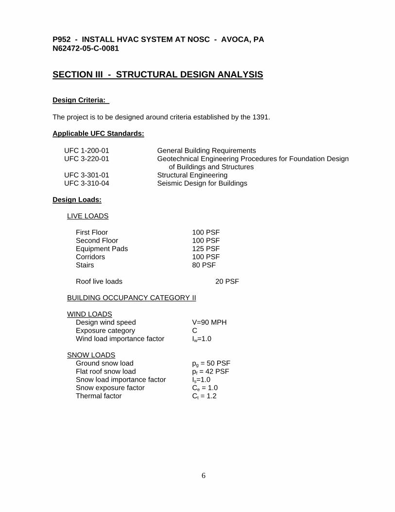
SECTION III - STRUCTURAL DESIGN ANALYSIS
Design Criteria:
The project is to be designed around criteria established by the 1391.
Applicable UFC Standards:
UFC 1-200-01 General Building Requirements UFC 3-220-01 Geotechnical Engineering Procedures for Foundation Design
of Buildings and Structures UFC 3-301-01 Structural Engineering UFC 3-310-04 Seismic Design for Buildings
Design Loads:
LIVE LOADS First Floor 100 PSF Second Floor 100 PSF Equipment Pads 125 PSF Corridors 100 PSF Stairs 80 PSF Roof live loads 20 PSF BUILDING OCCUPANCY CATEGORY II WIND LOADS Design wind speed V=90 MPH Exposure category C Wind load importance factor Iw=1.0 SNOW LOADS Ground snow load pg = 50 PSF Flat roof snow load pf = 42 PSF Snow load importance factor Is=1.0 Snow exposure factor Ce = 1.0 Thermal factor Ct = 1.2

7
EARTHQUAKE LOADS Mapped spectral response acceleration SS = 0.22 g S1 = 0.06 g Seismic load importance factor 1.0 Site classification D Design spectral response acceleration SDS = 0.23 g SD1 = 0.10 g
Seismic design category B Structural Materials:
Concrete Slab-on-grade f’c = 4,000 PSI Reinforcing steel ASTM A615, Grade 60 Welded wire fabric ASTM A185 Structural Steel Steel tube members ASTM A501, Grade B Fy = 46,000 PSI Steel pipe members ASTM A53 Fy = 36,000 PSI Steel wide-flange members ASTM A992 Fy = 50,000 PSI All other steel members ASTM A36 Fy = 36,000 PSI Anchor rods ASTM F1554 Grade 36 Bolts ASTM A325 Welding electrodes E-70-XX
Structural Scope of Work:
This project includes the following:
Three exterior equipment support pads for new chillers. Anchorage for canopies above new chillers. Angle support frame for a new intake air unit in the drill hall. Framing for reinforcing the existing second floor at an enlarged mechanical chase
opening. Miscellaneous duct/piping supports and anchorage as required.
Design shall be in accordance with the criteria listed above in coordination with all other disciplines. Minor selective structural demolition includes removal of existing exterior canopies and removal of a portion of the second floor where the existing mechanical chase is to be enlarged. Provide all temporary shoring as required to support the structure during demolition operations. Contact the engineer if any concerns arise regarding the structural integrity of the building or any of its components.

8
P952 - INSTALL HVAC SYSTEM AT NOSC - AVOCA, PA N62472-05-C-0081
SECTION IV - ARCHITECTURAL DESIGN ANALYSIS
Design Criteria: This project will be designed around criteria established by the 1391. The architectural design shall comply with the following UFC’s:
UFC 1-200-01, General Building Requirements, 2007 UFC 2-000-05N, Facility Planning Criteria, 2005 UFC 3-100-10, Architecture, 2006 UFC 3-120-10, Interior Design, 2006 UFC 4-010-01, DoD Minimum Antiterrorism Standards for Buildings, 2007
Architectural Scope of Work: The project’s purpose is to replace the existing Heating, Ventilation and Air Conditioning (HVAC) system in Building 1 at Naval Operation Support Center (NOSC) Avoca, PA. The project will also install a fire suppression and notification system and upgrade electrical systems.
The scope of architectural work includes the following:
1. Demolish all ACT drop ceilings and associated fixtures to perform Fire
Protection, HVAC and Electrical work. 2. Install new drop ceilings and metal stud/gypsum wallboard headers. Drop
ceilings will be kept back a distance from exterior walls with high windows, and gypsum wallboard headers will be installed to transition from drop ceiling to structural ceiling at the high windows. Structural concrete ceilings and metal deck ceilings left exposed to view will be cleaned and painted.
3. New walls and doors will be installed to create a new Electrical room, Storage room and Sprinkler Riser room.
4. Walls at the 2nd floor mechanical chase will be demolished and re-built to allow access into the chase for mechanical and plumbing work.
5. All A/C window units and associated infill window panels will be removed. New glazing will be installed at these window frames.
6. Through-wall A/C units at exterior and interior walls will be removed. The walls will be patched to match adjacent surfaces.
7. Demolish existing doors and install new doors at locations indicated in the drawing set. Existing door frames and hardware will be re-used.
8. Demolish the existing exterior metal canopy and install new metal canopies at exterior mechanical units for weather protection.
9. Minor roofing work to coordinate with new rooftop mechanical units. 10. Demolition of interior finishes to be coordinated with mechanical and electrical
demolition. Finishes to be patched and/or repaired. 11. Existing furniture will be moved and stored as needed to accommodate the
project phasing, allowing the building to be occupied during construction.

9
Personnel: The Using Activity for this project is planned to be: NAVAL RESERVE CENTER. Full time personnel occupy the building for 8 hours per day, five days per week. The staffing requirement is for 50 employees, with 70 parking spaces being provided. Accessibility: This is an existing facility with features that do not conform to current accessibility code. Due to the nature of this project (Fire Protection, Mechanical, Electrical), these conditions will not be remediated. Any new walls and doors will provide for required accessibility clearances.
Antiterrorism: This is an existing facility with features that do not conform to current AT/FP minimum design standards. The cost of this project is below 50% of the building’s replacement value, therefore, compliance with AT/FP standards are not required for this project.
Sustainable Design: Due to the nature of this project, full LEED or Sustainable Validation will not be utilized, however, sustainable design features will be incorporated into the project design as far as practicable.

10
P952 - INSTALL HVAC SYSTEM AT NOSC - AVOCA, PA N62472-05-C-0081 SECTION V - FIRE PROTECTION DESIGN ANALYSIS Fire Protection Modifications: The scope of general construction work associated with this project will include the removal and replacement of the fire alarm system and installation of a new sprinkler system. Due to the extent of work performed under the HVAC replacement, the fire protection systems will be upgraded. The work will occur in phases and the building will remain occupied during construction. Since the work will be in two phases, the work will be performed as follows: Phase I will include the Drill Hall and adjacent office and shop areas. The new sprinkler riser and main fire alarm/mass notification control panel will be installed in a new riser room which will be part of Storage 147. Phase II will be the remainder of the building. Upon final acceptance of the fire protection systems, the existing panel and devices will be removed and a combination local operating console (LOC) and annunciator installed in its place. References: UFC 3-600-01: Fire Protection Engineering for Facilities, dated 26 September 2006, Change 1, 14 July 2009 UFC 3-600-10N: Fire Protection Engineering, Final Draft dated August 2007 UFC 4-021-01: Design and O&M: Mass Notification Systems, dated 9 April 2008 International Building Code (IBC), 2006 edition NFPA 13, Standard for the Installation of Sprinkler Systems, 2010 edition NFPA 72, National Fire Alarm Code 2010 edition NFPA 101, Life Safety Code®, 2009 edition Automatic Sprinkler System: The NOSC requires complete automatic sprinkler protection in accordance with the requirements outlined in UFC 3-600-01 and installed in accordance with NFPA 13. A new 6-inch water main and fire hydrant will be installed on the south side of the building. A new flush-mounted fire department connection will be provided on the exterior of the building near the sprinkler riser room. Sprinkler protection for the building will be designed on the basis of the UFC 3-600-01, Appendix B, Occupancy Hazard Classification for Determining Automatic Sprinkler Densities and Hose Stream Demands classifies Offices as Light Hazard. UFC 3-600-01 Table 4-1 identifies the Light Hazard Design Requirements as follows: Occupancy Classification: Light Hazard Design Density: 0.10 gpm/sf Design Area: Hydraulically most remote 3,000 sf Hose Stream Allowance: 250 gpm Duration of supply: 60 minutes

11
The Mechanical Room and Storage Rooms will be protected as Ordinary Hazard Group 1 with the following design requirements per UFC 3-600-01: Occupancy Classification: Ordinary Hazard, Group 1 Design Density: 0.15 gpm/sf Design Area: Hydraulically most remote 3,000 sf Hose Stream Allowance: 500 gpm Duration of supply: 60 minutes Water Supply: A hydrant flow test was performed on 20 January 2010 at the existing fire hydrant adjacent to the building. Due to the layout of the water distribution system and having only a single hydrant near the NOSC, the single hydrant was both the flow and gauged hydrant. The flow test results were as follows: Static: 100 psi (pressure was in excess of 100 psi, the gauge was only 0-100 psi) Residual: 56 psi Pitot: 24 psi (using Pollard water diffuser) Flow: 822 gpm Flow at 20 psi: 1,135 gpm Fire Alarm/Mass Notification System: The new fire alarm and mass notification system will be installed in accordance with UFC 4-021-01 and NFPA 72. The system must be designed with necessary intelligibility (CIS .7 min.) per UFC 4-021-01 §5-7.1.2. Fire alarm and mass notification systems are permitted to be a single system and controlled by the fire alarm control panel (FACP). The main FACP is to be located in the new sprinkler riser room, which is currently Storage 147. A combination local operating console (LOC) and fire alarm annunciator panel will be installed at the Quarter Deck where the existing panel is currently located. Annunciation shall be integral to the panel. Manual pull stations are required and are located at all doors exiting the facility. On the Second Floor, the manual pull stations are required at the entrance to all stairways. Initiating devices consisting of water flow switches on the sprinkler riser, tamper switches on all normally open control valves and duct smoke detectors are shown on the drawings and shall be provided per NFPA 72. Duct smoke detectors will shut down the associated HVAC units upon an alarm signal. Notification appliances consist of speaker/strobes, strobes and speakers located in accordance with the requirements of NFPA 72 and UFC 4-021-01. Weatherproof speakers shall be provided at the main exits on the exterior of the building and shall be a minimum of 2 watts. The system will be arranged as Class A for all notification appliance circuits (NAC) and Class B for all signaling line circuits (SLC) and initiating device circuits (IDC). T-tapping of any circuits is prohibited. Power for the main FACP shall be connected to the dedicated power circuit from the Main Electrical Room (129). The breaker shall be red and provided with a non-sweep device (breaker lock).

12
P952 - INSTALL HVAC SYSTEM AT NOSC - AVOCA, PA N62472-05-C-0081 SECTION VI - MECHANICAL DESIGN ANALYSIS Existing Conditions - HVAC The NRC building is an approximately 34,197 square feet office and training facility comprised of three different functional spaces. The spaces include the two-story section with administration offices, locker rooms and several classrooms on the first floor and various classrooms on the second floor, one story gymnasium/assembly area, and one story section including medical training classrooms, gym room and facility lounge. The two-story section has partial basement serving as a mechanical equipment room for the whole building. Portions of the existing HVAC System was originally designed as 2-pipe heating/cooling changeover system to provide heating and cooling for the 2-story administration/classroom section and heating only for the one story gymnasium/assembly and medical training (former shop) area. Supply and return piping for two-story section was sized to be adequate for heating and cooling and separate circulation pumps were installed for the heating and future cooling systems. Condensate drain piping from terminal heating/cooling equipment was also provided for future use, but has never been used. Existing supply and return piping for the heating only and the heating/cooling system appears to be in good condition. Insulation is also in fair condition for the heating application, however portions of insulation are damaged and the vapor barrier is damaged on several locations of the dual temperature system. Almost entirely all of the HVAC (and domestic) piping throughout the facility is run exposed and has been field painted to a specific identification scheme. Outside air is ducted to various classrooms and offices of the 2-story section by a dedicated outdoor air-handling unit located in the basement mechanical room. Existing distribution ductwork is un-insulated, but appears to be in good condition. Outside air for the gymnasium (drill deck) and medical training areas is introduced by terminal HVAC equipment and is not fed from the dedicated outside air unit. Terminal 2-pipe heating/cooling fan coil units (and unit ventilators) are located along outside walls in classrooms and offices. The units provide heating during occupied and unoccupied periods. In most of the classrooms and offices custom wooden enclosures cover supply, return and condensate drain piping installed near the floor along the outside walls. The cabinetry also serves as return air plenum for the wall mounted fan coil / unit ventilator units. This arrangement may result in mold growth and IAQ problems. All of the terminal units are in very poor condition and have exceeded their useful life. Heating of various storage, toilet and locker rooms is accomplished by hydronic unit heaters, convectors and finned radiation. All heating only terminal units and unit ventilators throughout the building are almost 40 years old and have also exceeded their useful life. A gas fired cast iron boiler manufactured by H. B. Smith company with Power Flame dual fuel (however only natural gas is utilized at the site) single forced draft burner provides the source of hydronic heating. The boiler is 2,172,000 BTUH capacity, 14 years old and is in fair condition. The boiler is connected to an outdoor boiler stack by field insulated steel breeching. The system is zoned into 2 loops, each with a dedicated circulator pump. The pumps are of original

13
installation and also are in poor physical condition. A new expansion tank for the heating system was installed in 2005; however the compression type tanks remain abandoned in place. Since the chiller was never installed, there is no central air conditioning in the building. Various classrooms and offices have window or through the wall air conditioning units for temporary seasonal use. General exhaust from various toilet and locker rooms is ducted to several exhaust fans on the roof. The shower room has a through the wall exhaust fan which by initial appearance, appears to be undersized. All exhaust ductwork is in fair condition. All of the existing ductwork is also painted to match a specific color identification scheme. The majority of the old system will be removed this includes: All heating piping, Boiler and associated pumps, expansion tanks. Remove the heat exchanger in the basement and in the Drill Hall, also the units in the medical classroom and lounge room. All unit heaters, fan coil units, and window AC units. Proposed Systems - HVAC In an effort to minimize construction costs, it seems practical to provide a 2-pipe VRF heating/cooling system. This system design will provide heating and cooling for the entire building with individual room control sensors to provide a more energy efficient and comfortable building for all occupants. The scope of work shall be as follows:
1. Remove wooden pipe enclosure/return plenums in classrooms and offices. Provide new 2 pipe system that will enclose the pipes in soffits or in the ceiling cavity. The existing piping shall be removed.
2. Remove existing wall mounted fan coil units/unit ventilators in classrooms and offices and provide new wall mounted 2-pipe VRF cooling/heating fan coil units.
3. The existing piping serving terminal heating equipment in gym/assembly and former shop area was designed for heating only which will be removed. The new 2 pipe system will be newly routed and insulated to cover this area as well as all of the associated rooms within this building section. Remove all unit heaters and fan coil units. New ductwork will replace all of the existing ductwork in the Drill Hall/Offices adjacient to the Drill Hall.
4. Remove heating all unit ventilators serving; medical training rooms, exercise room and the lounge. Remove all associated supply ductwork and reheat coils and provide new 2-pipe ceiling mounted blower coil units. Medical training rooms shall be served by a single VRF System. The other spaces shall be served by the same VRF System.
5. Remove heating unit ventilator serving drill/assembly area and provide new 2-pipe VRF unit. New supply ductwork and supply grilles will be provided. Remove dedicated outside air unit serving the serving classroom/office sections of the building. This unit is located in the basement equipment room. Provide new dedicated outside air handling unit. New supply ductwork will be provided in all areas served.
6. Existing breeching within the boiler room shall be removed and capped at the interior wall.
7. Toilet and locker rooms exhaust fans to be replaced. The fans replaced shall be tied into the DDC system.
8. Reuse existing relief fan to meet new requirements.

14
9. A complete building DDC system shall be provided to control all terminal and central equipment. The DDC system shall change ventilation rates as well as temperature setpoints for occupied and unoccupied modes. This will allow for a significant decrease in ventilation air when certain areas of the facility are not occupied. This will result in a significant operational savings.
10. Remove existing window and through the wall air conditioning units throughout the building.
The existing ductwork appears to be in very good condition but will be replaced due to size requirements for new system. The upper floor corridor serves as a relief plenum exhausted out thru the roof. This is permitted by code since the corridor is supplied with outdoor at a greater rate than the supplied make-up air taken from the corridor. Where ductwork will require modification to accommodate heating / cooling upgrades, the appropriate fire dampers, etc. will be provided. The building will have an integrated DDC control system. Heating, Ventilating, and Air-conditioning (HVAC) Systems will meet this Criteria:
1. Comply with ASHRAE, American Society of Heating, Refrigeration and Air Conditioning Engineers, Inc.
2. Comply with IBC 2006, International Building Code 3. Comply with IMC, International Mechanical Code 4. Comply with FEMP, Federal Energy Management Program 5. Comply with Unified Facility Criteria (UFC):
a. UFC 1-200-01, General Building Requirements b. UFC 3-400-01, Energy Conservation c. UFC 3-400-02, Design: Engineering Weather Data d. UFC 3-400-10N, Mechanical Engineering e. UFC 3-410-02N, Heating, Ventilating, Air Conditioning, and Dehumidifying
Systems f. UFC 3-420-01, Plumbing Systems, 2004 g. UFC 3-800-10N, Environmental Engineering for Facility Construction h. UFC 4-010-01, DoD Minimum Antiterrorism Standards for Buildings
Design Conditions: Design conditions for the indoor and outdoor heating and cooling conditions are selected per UFC 3-400-10N and UFC 3-400-02. Heating design temperatures are selected for 99% occurrence value, cooling design temperatures are selected for non-mission-critical facility for the 1% occurrence value. Weather data of Wilkes Barre, Pennsylvania will be used to set design condition for Avoca, Pennsylvania: latitude 41.0 N, longitude 75.0 W.
Design Outdoor DB Outdoor WB Indoor DB Indoor Relative Wind Speed
Wind Prevail.
Condition Temperature Temperature Temperature Humidity Direction
Heating 3oF DB 8oF WB 70oF DB 30% RH min. 11.0mph WNW
Cooling 88oF DB 72oF WB 76oF DB 50%RH, 30%RH min. 12.2mph W
15
P952 - INSTALL HVAC SYSTEM AT NOSC - AVOCA, PA N62472-05-C-0081
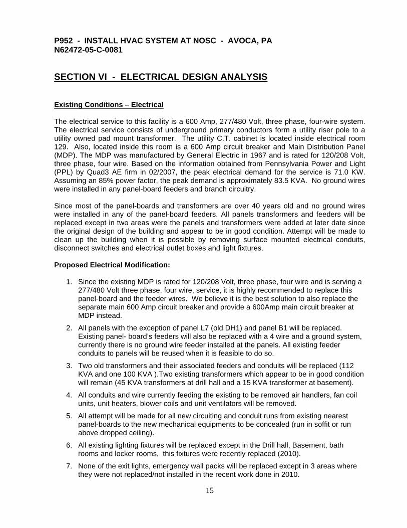
SECTION VI - ELECTRICAL DESIGN ANALYSIS Existing Conditions – Electrical The electrical service to this facility is a 600 Amp, 277/480 Volt, three phase, four-wire system. The electrical service consists of underground primary conductors form a utility riser pole to a utility owned pad mount transformer. The utility C.T. cabinet is located inside electrical room 129. Also, located inside this room is a 600 Amp circuit breaker and Main Distribution Panel (MDP). The MDP was manufactured by General Electric in 1967 and is rated for 120/208 Volt, three phase, four wire. Based on the information obtained from Pennsylvania Power and Light (PPL) by Quad3 AE firm in 02/2007, the peak electrical demand for the service is 71.0 KW. Assuming an 85% power factor, the peak demand is approximately 83.5 KVA. No ground wires were installed in any panel-board feeders and branch circuitry. Since most of the panel-boards and transformers are over 40 years old and no ground wires were installed in any of the panel-board feeders. All panels transformers and feeders will be replaced except in two areas were the panels and transformers were added at later date since the original design of the building and appear to be in good condition. Attempt will be made to clean up the building when it is possible by removing surface mounted electrical conduits, disconnect switches and electrical outlet boxes and light fixtures. Proposed Electrical Modification:
1. Since the existing MDP is rated for 120/208 Volt, three phase, four wire and is serving a 277/480 Volt three phase, four wire, service, it is highly recommended to replace this panel-board and the feeder wires. We believe it is the best solution to also replace the separate main 600 Amp circuit breaker and provide a 600Amp main circuit breaker at MDP instead.
2. All panels with the exception of panel L7 (old DH1) and panel B1 will be replaced. Existing panel- board’s feeders will also be replaced with a 4 wire and a ground system, currently there is no ground wire feeder installed at the panels. All existing feeder conduits to panels will be reused when it is feasible to do so.
3. Two old transformers and their associated feeders and conduits will be replaced (112 KVA and one 100 KVA ).Two existing transformers which appear to be in good condition will remain (45 KVA transformers at drill hall and a 15 KVA transformer at basement).
4. All conduits and wire currently feeding the existing to be removed air handlers, fan coil units, unit heaters, blower coils and unit ventilators will be removed.
5. All attempt will be made for all new circuiting and conduit runs from existing nearest panel-boards to the new mechanical equipments to be concealed (run in soffit or run above dropped ceiling).
6. All existing lighting fixtures will be replaced except in the Drill hall, Basement, bath rooms and locker rooms, this fixtures were recently replaced (2010).
7. None of the exit lights, emergency wall packs will be replaced except in 3 areas where they were not replaced/not installed in the recent work done in 2010.

16
8. The facility has a lot of exposed conduit runs and electrical equipments which will require additional work to improve and enhances the over all appearance of the facility. More electrical improvement work such as: Concealing existing exposed conduit runs, replacing/relocating existing electrical equipments and light fixture will be included in the project.
Electrical Load Analysis: The existing building load is 83.5KVA/100 Amps Based on the information obtained from Pennsylvania Power and Light (PPL) by the Quad3 AE firm in 02/2007. The load was divided evenly between LP-9, DH-1, two existing transformers and LP-A. TOTAL ELECTRICAL DESIGN LOADS AT MDP: Loads Connected Demand Existing Load 83.5 KVA 83.5 KVA HVAC (Panel P-1) 300 KVA 96.8 KVA Future Growth 45.0 KVA 45.0 KVA ____________________________________ Total 428.5 KVA 225.3 KVA Electrical Design Criteria:
UFC 3-501-01N Electrical Engineering UFC 3-520-01N Interior Electrical System UFC 3-530-01 Interior and Exterior Lighting and Controls UFC 1-300-09N Design Procedures NFPA 70 National Electrical Code
Wiring Methods: Insulated copper conductors installed in rigid steel conduit, IMC, rigid nonmetallic conduit or EMT, except where specifically indicated otherwise or required by NFPA 70. Grounding conductor shall be separate from electrical system neutral. Provide insulated green equipment grounding conductor for circuit(s) installed in conduit and raceways. Conductors: Unless specified or indicated otherwise or required by NFPA 70, power and lighting wires shall be 600 volt, Type THWN/THHN conforming to UL 83. Conductors No. 8 AWG and larger diameter shall be stranded. Standards of Design: Conductors of branch circuits shall be sized to prevent a voltage drop exceeding 3 percent at the furthest outlet of power, heating, and lighting loads, or combinations of such loads and where the maximum total voltage drop on both feeders and branch circuits to the furthest don’t exceed 5 percent. Lighting intensities will be as specified in the current edition of the Illuminating Engineers Society Handbook and will be 30 foot-candles for the basement mechanical room.

17
Control of the lighting circuits will be by wall mounted toggle switches that will be single pole. T-8 High Output fluorescent lamps with electronic ballasts, PF>0.95, THD, 15%, BF 0.85-1.2 will be used in the basement. Incandescent lighting fixtures will not be used; compact fluorescent technologies will be utilized instead. Motors shall be provided with motor disconnect switches. Motor control features will be coordinated with the Mechanical system design. Soft start or variable frequency starters will be used for motors larger than 20 hp.