overview of the earthcare multi-spectral imager and...
TRANSCRIPT

Changing the economics of space
Overview of the EarthCARE Multi-Spectral Imager and
Results from the Development of the
MSI Engineering Model
October 2012ICSO 2012
SSTL, TNO, ASD, ESA

Commercial in Confidence2
Overview• The EarthCARE Multispectral Imager (MSI)
– An Earth observing radiometric imager• intended to remotely determine cloud cover and cloud top surface temperature.• Part of suite of instruments on EarthCARE satellite
– 500m ground sample distance – Swath width of 150km– Seven spectral bands
Instrument Control Unit
MSI Optical Bench Module
Commercial in Confidence3
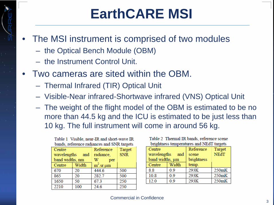
EarthCARE MSI• The MSI instrument is comprised of two modules
– the Optical Bench Module (OBM)– the Instrument Control Unit.
• Two cameras are sited within the OBM. – Thermal Infrared (TIR) Optical Unit– Visible-Near infrared-Shortwave infrared (VNS) Optical Unit– The weight of the flight model of the OBM is estimated to be no
more than 44.5 kg and the ICU is estimated to be just less than 10 kg. The full instrument will come in around 56 kg.

Commercial in Confidence4
Development Philosophy• Objective
– design and manufacture a complex, advanced technology instrument to meet a demanding set of technical constraints.
– minimize possible risk– achieve a challenging set of
schedule and cost targets. • Philosophy
– Hybrid of the (EQM) + Flight Model and the Proto-Flight Model (PFM) approaches.
– Early development of a product de-risking model, (Engineering Confidence Model / ECM)
• The key to the ECM is that only critical items are qualified, rather than the whole model.
• Mechanisms also have their own level models
Module Structural model
Intended for S/C level STM
Module Engineering model
Intended for S/C level EFM
Engineering model
Protoflight model

Commercial in Confidence5
VNS Optical Unit • The VNS consist of the following three assemblies, which are directly
mounted on the MSI Optical Bench:– VNS Camera with integrated VNS Calibration Mechanism– VNS SWIR-2 radiator– VNS Sun Calibration Baffle
• The VNS has two separate apertures – one 4.85mm diameter aperture for the VIS, NIR and SWIR-1 channels,– a second 10.47mm diameter aperture for the SWIR-2 channel.
J. Doornink, B. de Goeij, O. Marinescu, E. Meijer, R. Vink, W. Van Werkhoven, A. van ’t Hof, “The Visible, Near-Infrared and Short Wave Infrared Channels of the EarthCARE Multi-Spectral Imager” in proceedings of the International Conference on Space Optics, October 2010

Commercial in Confidence6
VNS Optical Unit - FPAs• In-orbit operating temperatures
– VIS/NIR and SWIR-1 detectors are 300K, – SWIR-2 is 235K.
• The reduced SWIR-2 temperature is implemented to achieve the required signal to noise levels and maintain interchannel radiometric accuracy.
• The SWIR-2 detector is thermally isolated from the VNS camera and thermally coupled to the VNS SWIR-2 radiator.

Commercial in Confidence7
VNS Calibration Mechanism & LTM• During the in-flight operations the VNS will be
regularly calibrated. – Dark measurements will be performed for
offset corrections during eclipse of the orbit; – Sun calibration will be performed for response
calibration during passes over the South Pole region.
• During the sun calibration the sun light will illuminate a pair of Quasi Volume Diffusers (QVD). The QVDs are mounted on a rotating carousel which is used to switch between dark, sun and earth viewing modes.
• First physical model of the VNS is the Life Test Model (LTM).
• VNS LTM test program:– Qualification level vibration testing.– Thermal Vacuum cycling (-30°C - +70°C).– Operation of the Mechanism for 56000 orbital
calibration cycles.– Operation of the mechanism for 560 monthly
calibration cycles.• VNS LTM successfully passed all these tests

Commercial in Confidence8
VNS ECM• Performance tests completed show:
– Focal length = 22.2mm– Field of View > +/-11.5 degrees of arc– Detector noise is well below the required 5000 electrons per read-out.– MTF performance above 0.4– Polarization sensitivity below 1.5%
• All these performance parameters are within their respective requirement.

Commercial in Confidence9
TIR Optical Unit• The internal layout of the TIR
comprises an f/8 telescope upstream of a dichroic and filter assembly which provides the spectral division into the 3 TIR bands.
• Downstream of this assembly is an f/1 relay lens, responsible for directing the 3 colour channels onto a 2D α-Si microbolometer detector.
• This system is read out in Time- Delay-Integration (TDI) mode.
• Performance tests are ongoing.– FoV > +/- 10 degrees– Static MTF > 0.49
M. P. J. L. Chang, D. Woods, G. Baister, D. Lobb, T. Wood, “The EarthCARE Multi Spectral Imager Thermal Infrared Optical Unit” in proceedings of the International Conference on Space Optics, October 2010
L. Gomez Rojas, M. Chang, G. Baister, G. Hopkinson, M. Maher, M. Price, M. Skipper, T. Wood, D. Woods, “The EarthCARE multispectral imager thermal infrared optical unit detection system design”, Proc. SPIE 7826, 7826H (2010); http://dx.doi.org/10.1117/12.869250

Commercial in Confidence10
TIR Optical Unit / Mechanism• The unit has three target
apertures –– the primary science Earth
(nadir) viewing port, – the Cold Space viewing
port for dark scene reference and
– the on-board calibration blackbody aperture providing the bright scene reference.
• Selection of one of 3 target apertures directed through the optical chain onto the focal plane assembly is performed by the TIR calibration mechanism assembly

Commercial in Confidence11
TIR Optical Unit / Blackbody
• The calibration blackbody is a passive component, monitored by high precision platinum resistance thermometers in the PFM / thermistors in the ECM.
• The qualification test flow is shown here. The component’s radiometric performance was proved in thermal test ranging over -40ºC to +70ºC.

Commercial in Confidence12
Front End Electronics • The FEE is an integral part of the MSI OBM as it serves to drive the
detectors and acquire all video signals and key telemetries associated with the 5 focal planes of the MSI.
• The optical unit ECMs are supported by 2 FEEs, as both units are manufactured and tested in parallel. These FEEs are not environmentally tested with the unit cameras and so are provided at breadboard maturity.

Commercial in Confidence13
Instrument Control Unit • The ICU is responsible
for handling all the spacecraft interfaces as well as ensuring the correct function and health of the instrument by performing the data handling, monitoring and control activities.
• The ICU plays no direct part in the MSI OBM ECM.
• There is an engineering model which serves to verify hardware requirements and interfaces and prove the initial Boot and Application Software releases. This model’s purpose is to feed into the EarthCARE spacecraft Electrical Functional Model.

Commercial in Confidence14
Conclusion• The units that go to make up the MSI ECM have been
discussed. • The results of the unit level ECM tests are expected by the
end of 2012, which should be followed closely by the independent ICU EM electrical and functional test results.
• The outcome will put the EarthCARE MSI project in a good position to move to MSI ECM integration; it will have the best information in the shortest practical timeframe.

Commercial in Confidence15
AcknowledgementsThe authors acknowledge the contribution by the
following programme participants: • Systems Engineering & Assessment Ltd as supplier
of the MSI ICU, • Scisys as supplier the MSI ICU software, • Xenics as supplier of the VNS detectors and • ABSL as supplier of the TIR calibration blackbody.
Thank you for your attention.