overview of data filtering/acquisition for a 411 detector ...lss.fnal.gov/conf/c851111/p.185.pdf ·...
TRANSCRIPT

185
OVERVIEW OF DATA FILTERING/ACQUISITIONFOR A 411" DETECTOR AT THE SSC*
Summary Report of the Data Filtering/Acquisition Working GroupSubgroup A: Requirements and Solutions
A. J. LANKFORD
Stanford Linear Accelerator CenterStanford University, Stanford, California, 94905
G.P. DUBOIS
California Institute of Technology, Pasadena, CA 911f5
1. Introduction
The task of the Data Filtering/Acquisition Working Group was to examinethe feasibility of acquiring data at SSC event rates from a 411" detector withapproximately three-quarters of a million electronic channels. The scope of thisexamination included all electronics between amplifiers on each detector elementand transfer of data to off-line computer facilities. In particular, subgroups ofthe working group examined (1) data buffering, digitization, and reduction, (2)architectures to handle the data flow from the electronics on the detector toan online farm of processors and to mass storage, (3) strategies for :reducing thetrigger rate using the processor farm, and (4) general considerations such as eventsizes and trigger rates.
This report provides an overview of the work on data filtering and acquisition. Section 2 reviews the assumptions made about the detector, event rates,and event sizes. Section 3 outlines the overall picture of data flow through thedata acquisition system. Section 4 describes the problems of and the generalapproach to handling of the data during analog and higher level trigger decisionperiods. Section 5 sketches flow of the data to the online processor farm. Section 6 comments on software trigger strategies. Section 7 sketches aspects of theoverall picture of a generic data acquisition system. Finally, Section 8 provides asummary of major issues and some needed developments. A number of separatereports, from subgroups or based on presentations made at the workshop, areincluded in the proceedings of the workshop and referenced by this overview.
* Work supported by the Department of Energy, contract DE-AC0376SF00515.

186
2. Data Flow Requirements of a 41r Detector
This section summarizes assumptions made by the Data Filtering/AcquisitionWorking Group about features of SSC performance, general 411' detectors, andtriggering which impact the design of a data acquisition system. In general, theseassumptions are drawn from the Proceedings of the 1984 Summer Study of theDesign and Utilization of the Superconducting Super Collider.1 In particular,please see "Detectors and Experiments for the Superconducting Super Collider" 2
by M.G.D. Gilchriese and "411' Detectors"3 by G.J. Feldman, M.G.D. Gilchriese,and J. Kirkby.
2.1 INTERACTION RATE AND TRIGGERS
The SSC design luminosity of 1033 cm-2 sec-I, with an expected total inelastic cross-section of approximately 100 mb, will yield an interaction rate of108 Hz. With 33 nsec between beam crossings, the crossing frequency will be3 X 107 Hz, and there will be 3.3 interactions per crossing.
The trigger will proceed in three stages: an Analog Trigger, followed by aHigher Level Trigger, and finally a Software Trigger. The results of the studies ofthe Analog Trigger4 and Higher Level TriggerS working groups at this workshopsuggest that the Analog Trigger will provide a rejection factor of about 1000in 1 p.sec, reducing the 3 X 10⁷ rate to between 104 and lOs Hz, and that theHigher Level Trigger, without using any digitized information, will provide anadditional rejection factor of about 100 in an additional 10 p.sec, reducing therate to between 100 an 1000 Hz. Further reduction in rate, to about 1 Hz is leftto the Software Trigger.
2.2 DETECTORS
The 411' Detectors Group at Snowmass '84 described three detector examplesin Ref. 3. Most details of the detector, and hence most differences between the detector examples, are not important to the general features of the data acquisitionsystem for the detector. Details of the type of detector and detector element occupancies will influence the details of the electronics of each channel as discussedin the report of the Hardware Subgroup of this working group.6 In addition, theoccupancies will determine the amount of multiplexing possible at various stagesin the data acquisition. In general, the extent of charged particle tracking, dueto the large number of measurements necessary per track, will determine theamount of data flowing through the data acquisition system. For that reason,the model detector considered here resembles the SCD detector of Ref. 3 withits complete charged particle tracking. However, in order to consider somewhat
-----------------•
•
•
•
•
--
--
187
more severe requirements, each wire in the model detector is considered to havepulse height measurement at both ends for third coordinate reconstruction.
The model detector for data acquisition considerations is:
1. Coverage of rapidity between ±5.5 units.
2. Charged particle tracking with 100 samples per track with drift times of100 nsec. 175,000 wires instrumented with drift time measurement andpulse height measurement at both ends.
3. Calorimetry with 50,000 towers of 3 longitudinal segments each. Widedynamic range pulse height measurement provided by two gain ranges.Some means of separating signals from nearby crossings.
4. Muon tracking with 100,000 wires with drift time and charge division measurements.
5. Vertex detection is to be treated as a special case and is not consideredhere.
6. Total electronics channel count is 850,000.
7. Some technique of waveform sampling will probably be used for signal digitization for all detector types, in order to provide the multihit capabilitynecessary for tracking devices and the pulse shape information necessary todeconvolute calorimeter pulses. The total information content of all samples before zero suppression will be 20-80 MByte depending on detectordetails.
2.3 EVENT SIZE
The typical minimum bias interaction at the SSC is expected to have aboutsix charged particles (and three neutrals) per unit of rapidity. Thus, there willbe about 66 charged tracks in the tracking detectors and about 100 charged andneutral particles in the calorimeters for the model detector covering 11 units ofrapidity.
For an event with a multijet trigger .with a jet threshold of 500 GeV, theremay be 30-40 charged particles per jet plus a background which resembles aminimum bias event. For two jets there will be about 150 charged tracks, and forfour jets there will be about 200 charged tracks. Typical event size calculationsuse 200 charged particles plus 100 neutrals.
The overall event size from the model detector will be dominated by thetracking chambers where there will be 100 hits per track (as compared with threesamples per calorimeter tower). In addition, during the 100 nsec drift time of
?

188
the tracking detector there will be signals from interactions during two or threeprevious beam crossings and two or three subsequent beam crossings. Thus,in addition to hits from tracks in the event of interest there will be hits fromthe equivalent of nine minimum bias events. The total number of hits is thenequivalent to the number from 800 charged particles, or 80,000 hits. Assumingthat the drift time, pulse height, and third coordinate measurements from eachwire can be reduced to five bytes including a wire label, the 80,000 hits willproduce 400 KBytes of charged particle information.
In the calorimeters there will be about 1200 particles assuming resolvingtimes of about 100 nsec, and three times as many for resolving times of 300 nsec.Allowing for two hit towers per particle on average and three hits per tower,there will be 720Q..22,OOO hits per trigger. However, with timing informationabout the hits, only hits from the events from different beam crossings than thetrigger can be rejected, leaving 3200 hits per trigger. At four bytes per hit,there would then be 12 KBytes per event. There may be multiple samples persignal if high occupancies demand that signals from different crossings on a singlechannel be deconvolved (see Ref. 6); however, we assume that this deconvolutionis performed in hardware and count only one sample per event. Furthermore, itwill be possible to pack the information from all three sections of a tower in sixbytes with a label, leaving only 6 KBytes per event. These numbers are in anycase negligible compared to the charged particle data. The quantity of data fromthe muon tracking system will also be negligible.
Thus, 400 KBytes of data are expected from a typical event after all reduction.
3. General Model of Data Flow
The general model of data How from the detector to off-line processing consistsof a series of stages, or levels, of processing, buffering, and filtering of the data.A level in the data acquisition system can be modelled as shown schematicallyin Fig. 1. An input data stream must be buffered while portions of the data areused to make a trigger decision. The buffer can be thought of most simply as adelay line into which data is placed for the length of time required'by the triggerdecision. The data appears at the output of the delay line as the trigger decisioncompletes. It is filtered, Le.: retained or discarded, according to whether thetrigger decision was "accept" or "reject". In reality, the buffer may be digital oranalog, or even a shift register or a physical delay line if it can preserve necessaryattributes of the signal throughout the decision time. The data stream can beprocessed at any point, before or after buffering and filtering.
--
•
--
•
•
-
-•
•
•

189
InputStream
L . To Trigger~_:L_--,I process ingL (oPtion~ J
1---- Trigger Decision
1-86
5322A2
Fig. 1. Representation of a level of buffering and processing in the data acquisitionsystem, corresponding to a level in thetrigger decision process.
The data acquisition model studied by the Data Filtering/Acquisition Working Group consists of three levels, corresponding to the Analog Trigger decision(Levell), the Higher Level Trigger decision (Level 2), and the Software Triggerdecision (Level 3). In fact, a considerable amount of flexibility is available. Morelevels are possible, and may simplify processing or data flow. Furthermore, anylevel can consist of sublevels, as will be necessary in levels involving extensiveprocessing such as Level 3. Processing, such as digitization, zero-suppression,correction, and compaction, can be applied at whatever point is convenient foroverall data flow considerations. Section 4 and Ref. 6 discuss Levels 1 and 2 of thedata acquisition. Sections 5 and 6 and Refs. 7 and 8 discuss Level 3. Figure 2outlines the three levels of the model used.
The inputs to Levell are the raw detector signals from the approximately850,000 electronic channels arriving at the beam crossing rate of 3 x 10⁷ Hz. Datais stored in the Level 1 buffer for the 1 J.Lsec required by the Level 1 trigger. TheLevel 1 buffer must be in effect dual-ported in order to avoid deadtime at theinput while data is being readout from it.
Input to Level 2 buffers is at the rate of 104-105 Levell triggers per second.Each event candidate is 20-80 MByte (or equivalent analog size) before zero
------------------
192
tracking measurements and, most likely, deconvolving calorimeter pulse heightmeasurements.
The basic solution to the problem of handling large amounts of data until theAnalog Trigger decision is to pipeline the data in some fashion on a channel-bychannel basis. In some cases, shift registers or analog delay lines may be sufficient;however, in most cases memories, either digital or analog, which can function ina dual-ported fashion would provide pipelined buffering which could be deadtimeless. Much preprocessing can be done on a channel-by-channel basis, whichwould also provide the necessary pipelining during the Higher Level Trigger decision. Alternatively, data could be buffered as during the Analog Trigger decision,and then preprocessed at the lower rate of accepted events from the Higher LevelTrigger. This solution offers either more preprocessing time or the opportunityto multiplex and thus save electronics. A considerable amount of flexibility isavailable in how data is buffered and when it is processed; however, choices depend upon the details of the detectors and possibly upon what data is needed bythe various levels of trigger. In all cases, the buffering and processing for largeamounts of detailed data will require new VLSI developments, such as improvedanalog memories, large dynamic range FADe's, specialized hardware processors,and multifunction circuits in a single package. These developments are within therealm of existing technology. The report of the Hardware Subgroup6 discussesin more detail the design of a possible solution to the problems of buffering andpreprocessing the large quantities of data. All solutions are expected to involvemuch local processing and data correction. Special-purpose processors to assistin the determination of calibration constants may be useful. Diagnostic featureswhich permit the testing of each stage of processing will be necessary.
5. Data Flow to the Online Processor Farm
With as many as 1000 Higher Level (Level 2) triggers per second and asmuch as 1 MByte per event, the required data flow capability between the detector component electronics and the processor farm must be 1 GigaByte persecond. In fact, some excess capacity must be available to handle variations inintervals between triggers. These large bandwidths can be handled by a manageable number of high-speed busses operating in parallel. For instance, twenty-fivebusses of 40 MByte capacity, which is similar to current FASTBUS capabilities,would provide the 1 GBytejsec necessary. Each bus would be fed from a buffercontaining data from some portion of the detector. The entire event is sent to asingle processor; consequently, each processor must have access to all the busses.Since the bandwidth into anyone processor is similar to the bandwidth of any
..
..
193
one bus, many events (as many as there are busses) must be in the process ofbeing transferred to as many processors at any moment. These considerationsare discussed in more detail in Refs. 9, 10, and 11 and in the report of the ModelArchitectures subgroup.7
6. Software Trigger Strategies
The Software Trigger must reduce an input trigger rate as high as 1000 Hzfrom the Higher Level Trigger to a final rate of about 1 Hz. The conditions whichthe Software Trigger will demand are dictated by the various physics processesbeing studied and will naturally be the logical "or" of several conditions. Mostsimple requirements will already have been applied by the hardware triggers.In fact, if the input rate to the Software Trigger is as low as 100 Hz, as theHigher Level Trigger Working Group at this workshop felt was possible, the ratewill be low because many of the trigger requirements will have been applied inhardware. Consequently, the tools available to the Software Trigger in reducingthe trigger rate will be determined by careful tradeoff with the hardware triggers.The hardware triggers in most instances will be faster, but the Software Triggerwill afford more flexibility. Information from the hardware triggers will guidethe Software Trigger. For instance, rather than attempting to reconstruct alltracks, the Software Trigger can simply confirm the tracks found by an efficienthardware track finder. Even if no hardware track finder is used by the HigherLevel Trigger, the Software Trigger will want such a device to increase its speed.
The Software Trigger, by offering the capability of fully reconstructing anevent, affords the trigger all the tools available ofHine in selecting events. However, full event reconstruction is expected to take about 1000 seconds on a VAXequivalent computer. Consequently, it will be impossible without a million VAXequivalents to fully reconstruct all the events input to the Software Trigger. Toreduce the amount of processing power required the Software Trigger must consist of levels, with progressively more time-consuming analysis occurring at thehigher levels. The actual bus architecture of the processor farm need not be tieredalthough the processing is. The Software Trigger algorithms must be carefullydesigned for execution speed. The Software Trigger should only confirm andpursue the conditions which caused the hardware trigger. For instance, if thehardware trigger tagged an event as a candidate for the decay of a W-pair intoleptons then the Software Trigger should not investigate the event as a possiblefour jet event. Reference 8 describes the Level 3 filters of the CDF experimentas an example of a software trigger and draws some implications for softwaretriggers at the SSC.

194
As an experiment develops at the SSC - as its physics goals and its hardwarebecome better understood - much of the event selection initially done offline canbe done online by the Software Trigger. Similarly, some data preprocessing andevent reconstruction done offline can be moved online. 'Computing power thatwould have been available offline for such processing could be placed online. Thedivision of computing power between online and offline is largely a logistical issue;however, the principal advantage of online event reconstruction, or reconstructionof portions of events such as track segments, would be to reduce the amountof data recorded per event in order to record more good physics events. Forinstance, the DST information on a fully reconstructed event will be two ordersof magnitude smaller than the reduced data input to the online processor farm.A spectrum of choices exist between a 1 Hz trigger rate of events with raw dataand a higher rate of events with track vectors only. The rate of processed eventswill be limited by the amount of processing available online.
7. Overall Online Computing
The overall organization of online computing for an SSC experiment can befairly conventional, similar to an online system for a LEP-generation experiment.This section very briefly describes the online computing necessary to managethe flow of data and to perform other online tasks. Since a fairly conventionalapproach appears to be adequate, this subject was not studied in depth at theworkshop.
The principal tasks to be performed by online computing include:
1. managing the flow of data from detector components to the processor farmand then to mass storage,
2. monitoring and controlling detector components,
3. determining and downloading detector constants,
4. providing support for the processor farm,
5. verifying the quality of the recorded data,
6. supporting detector and software development.
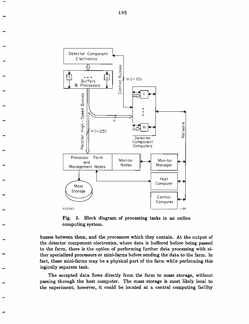
A block diagram of an organization of the processors necessary to perform thesetasks is shown in Fig. 3. The blocks in this diagram represent tasks to be performed; however, in most cases they also represent separate processors or groupsof processors to perform the tasks.
Sections 4 and 5 of this report have discussed the large blocks entitled "Detector Component Electronics" and "Processor Farm", the parallel high-speed
--------..----------..--
195
Detector ComponentElectronics
(j)
z
Mon i torManager
ControlComputer
HostComputer
DetectorComponentComputers
m (~IO)
MonitorNodes
en(j)enen:::l
CD
o~-co
U
...Buffers
8 Processors
en(j)enen:::l
CD
"(j)(j)Q.
(f)
I n£en
I n (~25)
~
0~
0Q.
Processor Farmand
Management Nodes
5322A3 1-86
Fig. 3. Block diagram of processing tasks in an onlinecomputing system.
busses between them, and the processors which they contain. At the output ofthe detector component electronics, where data is buffered before being passedto the farm, there is the option of performing further data processing with either specialized processors or mini-farms before sending the data to the farm. Infact, these mini-farms may be a physical part of the farm while performing thislogically separate task.
The accepted data flows directly from the farm to mass storage, withoutpassing through the host computer. The mass storage is most likely local tothe experiment; however, it could be located at a central computing facility
196
where it would be fed by a very high-speed optical link. On the other hand,offline computing power could also be local to the experiment, where it couldbe directly fed and maintained by the experiment and possibly flexibly allocatedbetween online (i.e.: real-time) and offline processing. Some considerations ofthe relationship between online and offline computing are discussed in the reportof the Off-line Computing and Networking Group.12
The detector is segmented into major detector components which are envisaged to be of a given detector type and to cover a certain region of solid angle.Each of these detector components will feed one of the twenty-five or so parallelhigh-speed busses along which the data flow to the processor farm. A detectorcomponent computer also resides on each of these busses. This computer, whichmay be of about the same power as present online computers, will be responsible for all tasks relating to the attached detector component which can be donewithout data from other detector components. For instance, it will be used inthe development and testing of the detector component and will perform monitor and control of the component. It will perform calibration of the detectorcomponent and download constants to the processors in the electronics of thecomponent. It will monitor raw data at various stages in the data acquisitionpreceding the farm and will control tests of all stages of data preprocessing. Itwill also act as a host for work relating to the detector component but demandingdata from other components, such as specialized monitoring of events selectedby the software trigger and graphic display of component performance. Duringdevelopment and calibration, the detector component computer will control thehigh-speed bus. During data acquisition, it will receive events in parallel as theyare sent to the farm. A separate bus, of perhaps lower bandwidth, between thecomputer and the detector component will probably be used to download andcontrol processors in the electronics and for detector monitor and control.
A portion of the large processor farm will be devoted to managing the triggering and preprocessing functions of the farm. Between ten and twenty VAXequivalents will be needed for this task. An additional function of the farm willbe monitoring data at various levels in the software trigger decision, both to verify the trigger and to inspect the quality of the data. Although this task couldbe performed by the general farm processors, it will probably be done by a set ofmonitor nodes which spy on the data flow through the farm. The monitor nodes,however, will be similar to the general processing nodes. The monitoring taskin the farm will be managed by a separate computer which will also collect anddispatch data from the monitor nodes to the detector component computers andto the main online host.
The role of the control computer is overall coordination and control of data
-
-
-
-
-
-
--------
-

197
acquisition. It will also provide centralized diagnostic and status reporting onthe performance of the detector during data taking. A separate host computermanages the processor farm, serves software development, and performs I/O. Alarge degree of flexibility is available in the division of tasks among the controlcomputer, the host, the monitor manager, and the detector component computers. In fact, a separate host computer may not be necessary. A local area networkwill interconnect these computers, along with any additional graphics devices orother peripherals. Uniform software tools, throughout all stages of the development, implementation, and operation of detector components and throughoutall levels of the data acquisition system, will be crucial to the operation of thecomplex system of online processors.
8. Summary
The difficult or new problems for data acquisition and filtering posed by alarge detector at the sse include:
1. buffering large amounts of data for large numbers of event candidates duringtrigger processing, even during the fastest possible analog trigger decisions,
2. preprocessing and reducing the complex waveform samples that will berequired to separate signals of events from different beam crossings,
3. transferring large amounts of data,
4. effectively reducing the trigger rate by orders of magnitude using softwarefilters,
5. managing very large arrays of processors, both in a processor farm andembedded in detector electronics,
6. reducing, rather than increasing, the large offline computing load presentedby the vast amount of data.
The solutions to these problems seem feasible; however, developments in a number of areas are necessary to realize the solutions. These developments include:
1. further development of custom chips for front-end electronics, chips withlarge dynamic range, storage of samples covering a microsecond, deadtimeless readout, and manageable calibration,
2. development of custom chips for data preprocessing and reduction,
3. experience managing large data transfer rates into processor farms,
4. study of trigger criteria in their physics context and study of the divisionof criteria between hardware and software triggers,
198
5. experience managing large processor farms, as well as large online computing systems,
6. integrated design of detectors and their data acquisition and study of thedivision of processing between online and ofHine computing.
Much of this development will naturally arise as part of the experimental program at accelerators currently in use or under construction, such as the pp ande+e- colliders. Extrapolation from the scale of detectors of that generation toSSC detectors will be believable. Workshops and electronics R&D programs canalso continue to address these issues, particularly as approaches to SSC detectordesign continue to develop.
References
1. Proceedings of the 1984 Summer Study on the Design and Utilization ofthe Superconducting Super Collider, June 23-July 13, 1984, Snowmass,Colorado (Ed.: R. Donaldson and J.G. Morfin).
2. M.G.D. Gilchriese, "Detectors and Experiments for the SuperconductingSuper Collider" , Proceedings of the 1984 Summer Study on the Design andUtilization of the Superconducting Super Collider, June 23-July 13, 1984,Snowmass, Colorado, pp. 491-522.
3. G.J. Feldman, M.G.D. Gilchriese, and J. Kirkby, "471' Detectors", Proceedings of the 1984 Summer Study on the Design and Utilization of the Superconducting Super Collider, June 23-July 13, 1984, Snowmass, Colorado,pp. 623-634.
4. Paolo Franzini, report of the Analog Triggers Working Group, submittedto the Workshop on Triggering, Data Acquisition and Computing for HighEnergy/High Luminosity Hadron-Hadron Colliders, Fermilab, November11-14, 1985.
5. M.A. Abolins and M.J. Shochet, report of the Higher Level Triggers Working Group, submitted to the Workshop on Triggering, Data Acquisitionand Computing for High Energy/High Luminosity Hadron-Hadron Colliders, Fermilab, November 11-14, 1985.
6. Peter S. Cooper, "A Feasibility Design for the Readout of a 471' SSC Detector; Data Filtering - Acquisition Group, Report of the Hardware Subgroup", submitted to the Workshop on Triggering, Data Acquisition andComputing for High Energy/High Luminosity Hadron-Hadron Colliders,Fermilab, November 11-14, 1985.
----------------
----

199
7. David Cutts, report of the Model Architectures Subgroup of the Data Filtering/Acquisition Working Group, submitted to the Workshop on Triggering, Data Acquisition and Computing for High Energy/High LuminosityHadron-Hadron Colliders, Fermilab, November 11-14, 1985.
8. J.T. Carroll, "Level 3 Filters at CDF", submitted to the Workshop on Triggering, Data Acquisition and Computing for High Energy/High LuminosityHadron-Hadron Colliders, Fermilab, November 11-14, 1985.
9. D.J. Linglin, "UA-l Software and Computing", submitted to the Workshopon Triggering, Data Acquisition and Computing for High Energy/High Luminosity Hadron-Hadron Colliders, Fermilab, November 11-14, 1985.
10. T.J. Devlin, "Data Rates for Event Builders and Farms", submitted tothe Workshop on Triggering, Data Acquisition and Computing for HighEnergy/High Luminosity Hadron-Hadron Colliders, Fermilab, November11-14, 1985.
11. L.R. Fortney, report on models of event building in processor farms, submitted to the Workshop on Triggering, Data Acquisition and Computing for High Energy/High Luminosity Hadron-Hadron Colliders, Fermilab,November 11-14, 1985.
12. M.G.D. Gilchriese and S.C. Loken, reports of the Off-Line Computingand Networking Working Group, submitted to the Workshop on Triggering, Data Acquisition and Computing for High Energy/High LuminosityHadron-Hadron Colliders, Fermilab, November 11-14, 1985.