orange county is dependent upon imported water the ...orange county is dependent upon imported water...
TRANSCRIPT
Orange County is dependent upon imported water from the Colorado River and Northern California for 75 percent of its supply. More than half of Southern California's former entitlement of Colorado River water was lost to Arizona by a 1964 Supreme Court ru ling. The Central Arizona Project began delivering water to Phoenix in 1986.
To make up for the loss of Colorado I~iver supply, the Northern California State Water Project must be completed. The Northern system can currently only deliver about half of the amount originally planned ~or, and what will be needed by the year 2000.
In the meantime, water conservation must be an integral part of our daily lives in Orange County. Water reclamation and reuse projects will help, but everyone's cooperation is needed to extend this vital resource.
For additional information, or to arrange for a speaker on water reuse, groundwater management or other water related programs, contact the District's Information Officer.

ORANGE COUNTY WATER DISTRICT
Orange County, California, is one of the most dynamic urban regions in the nation. The semi-arid coastal plain receives thirteen inches of rainfall annually and yet sustains a population of 1.9 million. The natural flows of the Santa Ana River and its tributary creeks combine with local precipitation to provide barely 25 percent of the total water demand.
The Orange County Water District boundary overlies a massive groundwater basin located in the northwest part of Orange County. This underground water basin was used by early settlers to supplement the river flows. As the area developed into an important agricultural center, the increased demand upon the subsurface water by the county's many wells resulted in a gradual lowering of the water table . The Orange County Water District was formed by an act of the California Legislature in 1933 to protect and manage the groundwater basin.
Continued growth within the county caused an accumulated overdraft of the basin. To prevent depletion of the basin and to sustain an adequate amount of groundwater to meet increasing demands, OCWD began purchasing surplus Colorado River water in 1949 for groundwater recharge. Northern California water deliveries for replenishment began in 1973.
Other solutions will be needed to alleviate the shortages, however. Importing water is becoming more costly as fuel prices escalate. The allotment from the Colorado River has been reduced 55 percent and increased deliveries from Northern California are dependent upon completion of the State Water Project. The latter has been deferred pending resolution of complex political, environmental and legal issues. As it becomes more difficult to obtain fresh water in Orange County and as water demand increases, the necessity of conserving and recycling water becomes clear.
LOS ANGELES COUNTY
PACIFIC OCEAN
LOCATION
SAN BERNARDINO COUNTY
' ._. _ .'-. j
(
RIVE RSIDE COU NTY
\ -.,L . ____
'> /
/
ORANGE COUNTY WATER DISTRICT
Director
Kathryn L. Barr John V. Fonley Lawrence P. Kraemer, Jr. Philip L. Anthony Langdon W. Owen Noble J. Waite Donn Hall John Garthe August F. Lenain Robert L. Clark
BOARD OF DIRECTORS
Division
- Garden Grove 2 - Orange 3 - Placentia 4 - Cypress-Stanton 5 - Irvine-Tustin 6 - Huntington Beach 7 - Costa Mesa 8 - Santa Ana 9 - Anaheim
10 - Fullerton

COASTAL BARRIER PROJECT
When extensive pumping of the groundwater basin lowers the water table below sea level, as occured in 1956, seawater may contaminate the basin, particularly along the coast. Tests have shown traces of saltwater as far as five miles inland. The area of intrusion is primarily across a three-mile front between Newport and Huntington Beach known as Talbert Gap. The mouth of an alluvial fan formed millions of years ago by the Santa Ana River, the Talbert Gap has since been buried along the coast by several hundred feet of clay.
Massive intrusion has been prevented by the District's recharge program. However, the threat of saltwater encroachment is still present. To prevent further intrusion and to provide basin management flexibility, the District operates a hydraulic barrier system. Seven extraction wells, approximately two miles from the coast, intercept brackish water and return it to the ocean. A series of 23 injection wells further inland deliver fresh water into the underground aquifers to form a water mound, blocking further passage of seawater.
Several alternative sources of water were throughly evaluated for the coastal project injection program, including deep well water, imported water, reclaimed wastewater, and desalted seawater. The source of injection water finally adopted for Water Factory 21 is a blended combination of reclaimed water and deep well water. There were many reasons for this decision. Cost was a definite consideration , but even more important were the environmental advantages:
• Reduction of 15,000 acre-feet (18.5 cubic hectometers) of waste discharge to the ocean annually.
• Reduction of dependency on Northern California and Colorado River water supplies.
• Constant availability of reclaimed water supply when imported supplies are diminished by drought or emergency interruption of importation systems.
~~-+-U~~~~~~~~ ..~~/ Q)
I U « w Q)
I CfJ I CfJ
~,~L-___________~
EXTRACTION ~ c.-~~·---8
\ ~ -tf------ 1...----+--1
• MULTI-CASING INJECTION WELLS
;:. EXTRACTION WELLS COASTAL SEAWATER
BARRIER PROJECT
Aerial view of Water Factory 21
-~
INFLUENT FROM SANITATION DISTRICT
RAPID MIXING
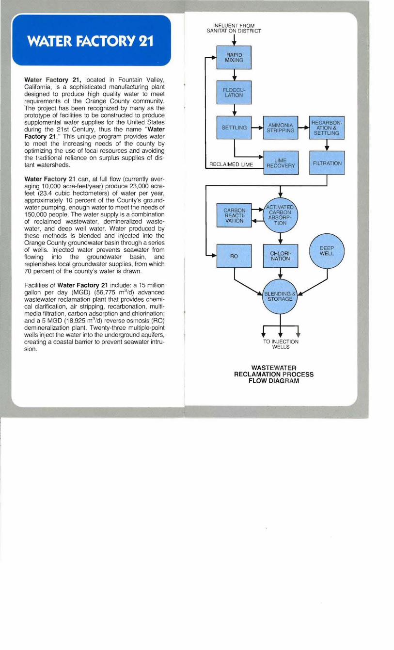
Water Factory 21, located in Fountain Valley, California, is a sophisticated manufacturing plant designed to produce high quality water to meet requirements of the Orange County community. The project has been recognized by many as the prototype of facilities to be constructed to produce supplemental water supplies for the United States during the 21 st Century, thus the name "Water Factory 21 ." This unique program provides water to meet the increasing needs of the county by optimizing the use of local resources and avoiding the traditional reliance on surplus supplies of distant watersheds.
Water Factory 21 can, at full flow (currently averaging 10,000 acre-feet/year) produce 23,000 acrefeet (23.4 cubic hectometers) of water per year, approximately 10 percent of the County's groundwater pumping, enough water to meet the needs of 150,000 people. The water supply is a combination of reclaimed wastewater, demineralized wastewater, and deep well water. Water produced by these methods is blended and injected into the Orange County groundwater basin through a series of we lls. Injected water prevents seawater from flowing into the groundwater basin , and replenishes local groundwater supplies, from which 70 percent of the county's water is drawn.
Facilities of Water Factory 21 include: a 15 million gallon per day (MGD) (56,775 m3 /d) advanced wastewater reclamation plant that provides chemical clarification, air stripping, recarbonation, multimedia fil tration, carbon adsorption and chlorination ; and a 5 MGD (18,925 m3/d) reverse osmosis (RO) demineralization plant. Twenty-three multiple-point wells inject the water into the underground aquifers, creating a coastal barrier to prevent seawater intrusion.
FLOCCULATION
RECAABONAMMONIA SETTUNG AT10N & STRIPPING SETTLING
LIME FILTRATION .....R_E_C_LA_I_M_E_D_L_IM;...E_-l RECOVERY
CARBON REACTIVATION
RO
TO INJECTION WELLS
WASTEWATER RECLAMATION PROCESS
FLOW DIAGRAM

Chemical clarification is accomplished in separate rapid-mix, flocculation and sedimentation basins. Lime is added in slurry form into the rapid-mix basin as a primary coagulant, and an anionic polymer is added as a settling aid in the third-stage flocculation basin . A lime dose of 400 mg/L as calcium oxide is automatically control led to maintain an optimum operational wastewater pH of 11 to 11 .3. A polymer dose of 0.1 mg/L is sufficient to insure good clarification.
Water flows from the bottom of the third flocculation basin into a settling basin where it flows horizontally and upward over V-notched weirs and out through collection troughs. The settling basin 's design overflow rate is 1,560 gallons per day/ft2 at 15 MGD (0.7 Usec/m2 at 56,775 m3 /day).
Chemical clarification is a highly effective process for reducing turbidity, organics, trace metals and phosphate, and for elevating pH for disinfection and virus removal.
Approximate detention time in the clarification basin is 117 minutes: one minute for each of the two rapid-mix basins, 30 minutes in the flocculation basins and 85 minutes in the settling basins.
Weir col/eets clarified water
Air stripping of ammonia nitrogen and volatile organics can be accomplished in two large air stripping towers operated in series. Wastewater is pumped from the clarification basin to the top of the towers and then sprayed down through a series of five splash bar bund les constructed of polypropylene tubing, totaling 25 feet (7.6 m) in height. The 1728 splash bar bundles have been designed as removable modules, approximately 5 foot (1.5 m) cubes, to facilitate periodic cleaning.
Continuous operation of the stripping tower fans is no longer required, because of changes in: influent water quality characteristics; regulations for ammonia concentrations in the injection water; and Water Factory 21 's method of operation. The fans were turned off in Apri l 1978 and the system is now operated primarily for removal of volatile organics, using only natural ventilation . While this air stripping process has been very effective, it may be necessary at some time in the future to restart the fans to remove more ammonia.
Air stripping tower
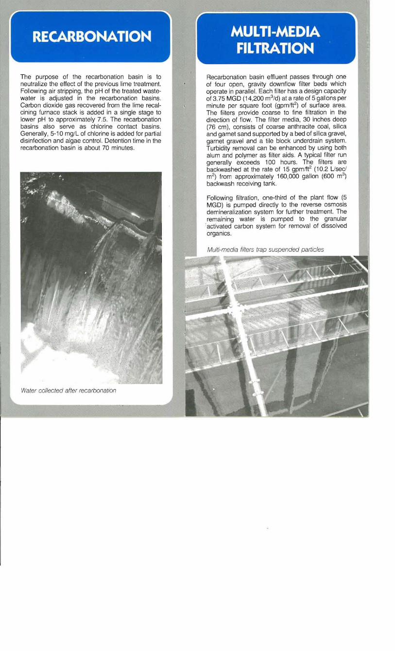
The purpose of the recarbonation basin is to neutralize the effect of the previous lime treatment. Following air stripping, the pH of the treated wastewater is adjusted in the recarbonation basins. Carbon dioxide gas recovered from the lime recalcining furnace stack is added in a single stage to lower pH to approximately 7.5. The recarbonation basins also serve as chlorine contact basins. Generally, 5-10 mg/L of chlorine is added for partial disinfection and algae control. Detention time in the recarbonation basin is about 70 minutes.
Water collected after recarbonation
Recarbonation basin effluent passes through one of four open, gravity downflow filter beds which operate in parallel. Each filter has a design capacity of 3.75 MGD (14,200 m3/d) at a rate of 5 gallons per minute per square foot (gpm/ft2) of surface area. The filters provide coarse to fine filtration in the direction of flow. The filter media, 30 inches deep (76 cm), consists of coarse anthracite coal, silica and garnet sand supported by a bed of silica gravel, garnet gravel and a tile block underdrain system. Turbidity removal can be enhanced by using both alum and polymer as filter aids. A typical filter run generally exceeds 100 hours. The filters are backwashed at the rate of 15 gpm/ft2 (10.2 Usec/
3m2) from approximately 160,000 gallon (600 m )
backwash receiving tank.
Following filtration, one-third of the plant flow (5 MGD) is pumped directly to the reverse osmosis demineralization system for further treatment. The remaining water is pumped to the granular . activated carbon system for removal of dissolved organics.
Multi-media filters trap suspended particles
ACTIVATED CARBON ADSORPTION
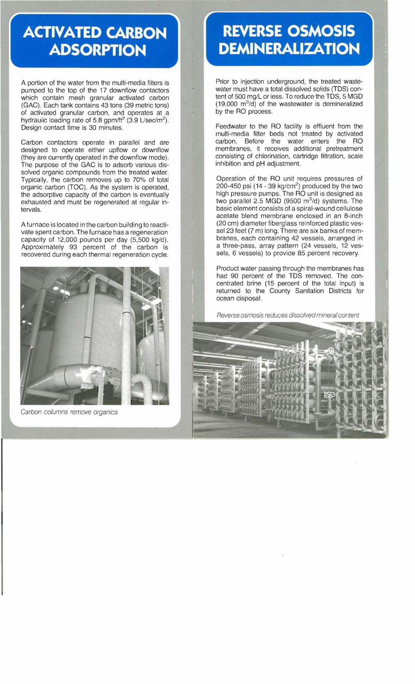
A portion of the water from the multi-media filters is pumped to the top of the 17 downflow contactors which contain mesh granular activated carbon (GAC) . Each tank contains 43 tons (39 metric tons) of activated granular carbon , and operates at a hydraulic loading rate of 5.8 gpm/ft2 (3.9 Usec/m2). Design contact time is 30 minutes.
Carbon contactors operate in parallel and are designed to operate either upflow or downflow (they are currently operated in the downflow mode). The purpose of the GAC is to adsorb various dissolved organic compounds from the treated water. Typically, the carbon removes up to 70% of total organic carbon (TOC) . As the system is operated, the adsorptive capacity of the carbon is eventually exhausted and must be regenerated at regular intervals.
A furnace is located in the carbon building to reactivate spent carbon. The furnace has a regeneration capacity of 12,000 pounds per day (5 ,500 kg/d) . Approximately 93 percent of the carbon is recovered during each thermal regeneration cycle .
Carbon columns remove organics
REVERSE OSMOSIS DEMINERALIZATION
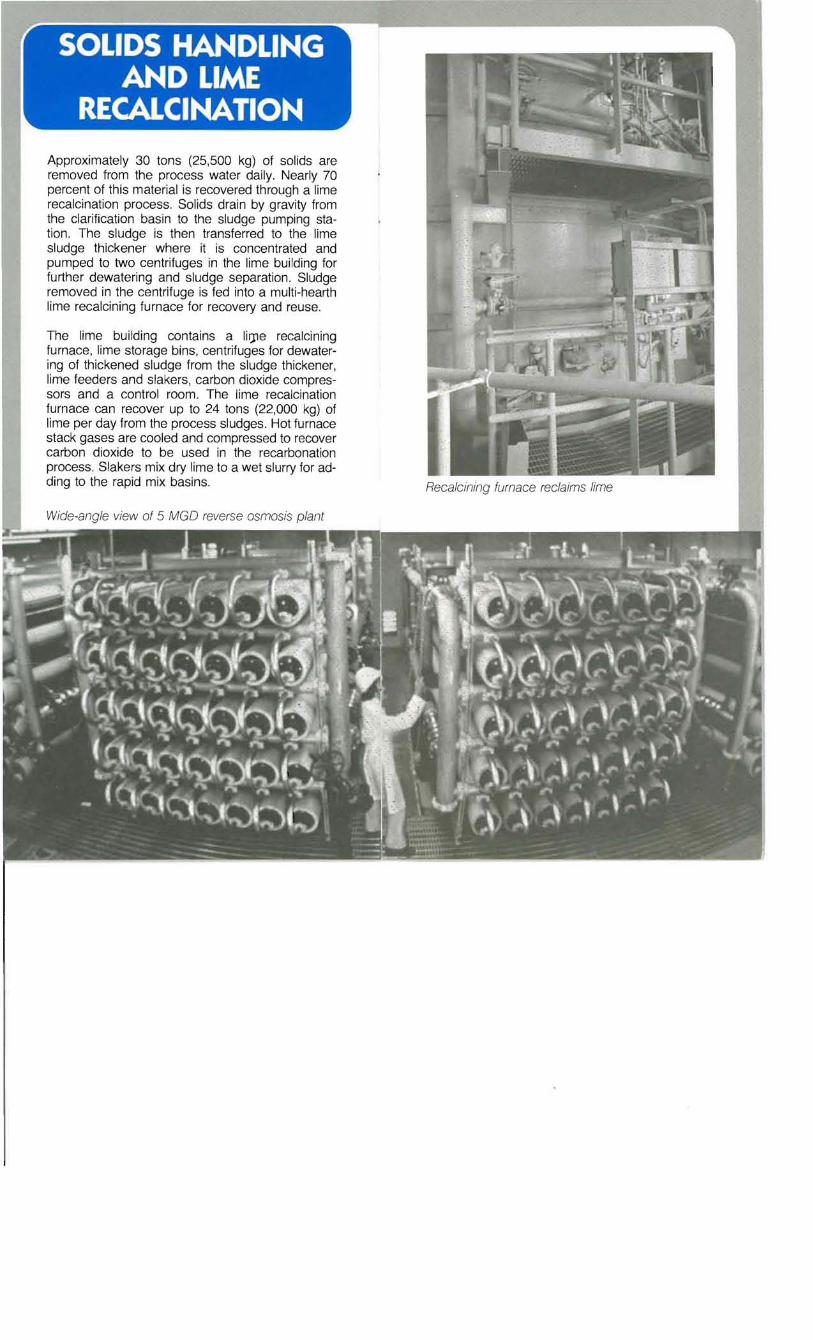
Prior to injection underground, the treated wastewater must have a total dissolved solids (TDS) content of 500 mg/L or less. To reduce the TDS, 5 MGD (19,000 m3 /d) of the wastewater is demineralized by the RO process.
Feedwater to the RO facility is effluent from the multi-media filter beds not treated by activated carbon. Before the water enters the RO membranes, it receives additional pretreatment conSisting of chlorination, cartridge filtration, scale inhibition and pH adjustment.
Operation of the RO unit requires pressures of 200-450 psi (14 - 39 kg/cm2) produced by the two high pressure pumps. The RO unit is designed as two parallel 2.5 MGD (9500 m3 /d) systems. The basic element consists of a spiral-wound cellulose acetate blend membrane enclosed in an 8-inch (20 cm) diameter fiberglass reinforced plastic vessel 23 feet (7 m) long. There are six banks of membranes, each containing 42 vessels, arranged in a three-pass , array pattern (24 vessels, 12 vessels, 6 vessels) to provide 85 percent recovery.
Product water passing through the membranes has had 90 percent of the TDS removed. The concentrated brine (15 percent of the total input) is returned to the County Sanitation Districts for ocean disposal.

CHLORINATION AND BLENDING
The chlorination basin , 90 feet by 53 feet (27 m by 16 m), is baffled to provide a serpentine flow path for the water. Effluent from the carbon columns flows to the chlorine contact basin for chlorination to oxidize residual ammonia, and to destroy remaining bacteria and virus. Chlorine is added , through a diffuser in the pipeline, just upstream of the entrance to the contact basin. Effluent from the chlorination basin flows by gravity to the blending and storage reservoir where it mixes with demineralized wastewater and deep well water.
The District is required by the California Department of Public Health to blend the activated carbon treated reclaimed wastewater with at least an equal quantity of demineralized or deep well water prior to groundwater injection. Injected water must also contain no more than 500 mg/L TDS. Blending water is obtained from RO demineralized water or by pumping from four separate wells 1,000 feet (300 m) deep, each capable of producing about 3,000 gpm (190 Usec) through 200 h.p.(150 kw) pumps. Blending reduces the TDS of the final product water below the 500 mg/L TDS limit.
The purpose of Water Factory 21 is to produce a water supply for the seawater barrier injection system. Final plant effluent, meeting all U.S. Public Health Service drinking water standards, is pumped into the underground basins via a series of 23 multi-casing injection we lls (81 individual injection points) placed approximately every 600 feet (200 m) along Ellis Avenue from the Santa Ana River to the bluffs at Beach Boulevard. This injected water forms a fresh water mound between the ocean and the groundwater basin, providing a hydraulic barrier to seawater intrusion and permitting the groundwater basin to be safely drawn below sea level.
Once underground, some of the injected water flows toward the ocean forming the seawater barrier. The majority of the water, however, flows into the groundwater basin to augment Orange County's domestic groundwater supply.
200' ·300'
~ 325 ' . 350'
MULTI-CASING INJECTION WELLS
Approximately 30 tons (25,500 kg) of solids are removed from the process water daily. Nearly 70 percent of this material is recovered through a lime recalcination process. Solids drain by gravity from the clarification basin to the sludge pumping station. The sludge is then transferred to the lime sludge thickener where it is concentrated and pumped to two centrifuges in the lime building for further dewatering and sludge separation. Sludge removed in the centrifuge is fed into a multi-hearth lime recalcining furnace for recovery and reuse.
The lime building contains a lilJle recalcining furnace, lime storage bins, centrifuges for dewatering of thickened sludge from the sludge thickener, lime feeders and slakers, carbon dioxide compressors and a control room . The lime recalcination furnace can recover up to 24 tons (22,000 kg) of lime per day from the process sludges. Hot furnace stack gases are cooled and compressed to recover carbon dioxide to be used in the recarbonation process. Siakers mix dry lime to a wet slurry for adding to the rapid mix basins.
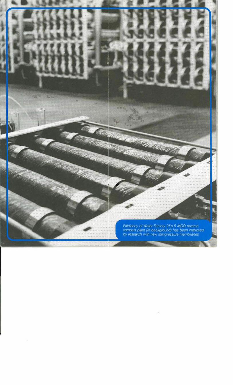
Wide -angle view of 5 MGD reverse osmosis plant
Recalcining furnace reclaims lime
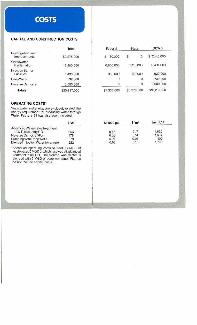
CAPITAL AND CONSTRUCTION COSTS
Total Investigations and
Improvements $2,275,000
Wastewater Reclamation 13,400,000
Injection Barrier Facilities 1,430,000
Deep Wells 732,000
Reverse Osmosis 3,000,000
Totals $20,837,000
OPERATING COSTS* Since water and energy are so closely related , the energy requirement for producing water through Water Factory 21 has also been included .
$/AF
Advanced WaterwaterTreatment (AWT) excluding RO 206
Reverse Osmosis (RO) 176 Pumping from Deep Wells 78 Blended Injection Water (Average) 222
*Based on operating costs to treat 15 MGD of wastewater, 5 MGD of which rece ives all advanced treatment plus RO. The treated wastewater is blended with 6 MGD of deep well water. Figures do not include capital costs .
Federal State OCWD
$ 130,000 $ 0 $ 2,145,000
6,850,000 3,116,000 3,434,000
350,000 160,000 920 ,000
0 0 732,000
0 0 3,000,000
$7,330,000 $3,276,000 $10,231 ,000
$/1000 gal. $/m3 kwh/AF
0.63 0.17 1,660 0.53 0.14 1,694 0.24 0.06 400 0.68 0.18 1,795
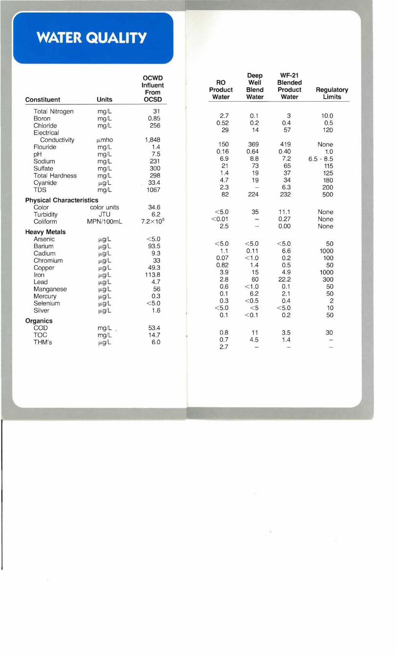
Constituent Units
OCWD Influent
From OCSD
RO Product Water
Deep Well
Blend Water
WF-21 Blended Product Water
Regulatory Limits
Total Nitrogen Boron Chloride Electrical
mg/L mg/L mg/L
31 0.85 256
2.7 0.52
29
0.1 0.2 14
3 0.4 57
10.0 0.5 120
Conductivity Flouride pH Sodium Sulfate Total Hardness Cyanide TDS
fJ. mho mg/L mg/L mg/L mg/L mg/L fJ.g/L mg/L
1,848 1.4 7.5
231 300 298
33.4 1067
150 0.16
6.9 21 1.4 4.7 2.3 82
369 0.64
8.8 73 19 19
224
419 0.40
7.2 65 37 34 6.3
232
None 1.0
6.5 - 8.5 115 125 180 200 500
Physical Characteristics Color Turbidity Coliform
color units JTU
MPN/100mL
34.6 6.2
7.2x10⁵
< 5.0 < 0.01
2.5
35 11 .1 0.27 0.00
None None None
Heavy Metals Arsenic Barium Cadium Chromium Copper Iron Lead Manganese Mercury Selenium Silver
f.lg/L f.lg/L f.lg/L f.lg/L f.lg/L f.lg/L fJ.g/L fJ.g/L fJ.g/L fJ.g/L fJ.g/L
< 5.0 93.5
9.3 33
49.3 113.8
4.7 56 0.3
<5.0 1.6
< 5.0 1.1
0.07 0.82
3.9 2.8 0.6 0.1 0.3
< 5.0 0.1
< 5.0 0.11 < 1.0
1.4 15 60
<1.0 6.2
< 0.5 < 5
< 0.1
< 5.0 6.6 0.2 0.5 4.9
22.2 0.1 2.1 0.4
< 5.0 0.2
50 1000
100 50
1000 300
50 50
2 10 50
Organics COD TOC THM's
mg/L mg/L f.lg/L
53.4 14.7 6.0
0.8 0.7 2.7
11 4.5
3.5 1.4
30