optional. form no. 10 ,1 nay iqa2 soition oa s gen. …
TRANSCRIPT

OPTIONAL. FORM NO. 10 !O%P 4-65)
1616- c ,1 NAY IQA2 SOITION
OA S GEN. RCG. NO. 21
U1 iTED STAI'ES GOVrRN?e EN'r HYDRAULICS BRANCH
A r, OFFICIAL FILE COPY
,itemorandum Memorandum Denver, Colorado
TO :Chief, Water Conveyance Branch DATE-.October 24, 1975
Attention: 224 THROUGH: Chief, Division of Design
Chief., Division of General Research Chief, Hydraulics Branch
A FROM :head, Hydraulics Research Section
~SUBJECT:Study of Flow Characteristics of Wade Pain Hydrant Valve Proposed for Spokane Indian Reservation ~.,rater Resource Development, Columbia Basin Project (Refer to March 17, 1975 Memorandum Requesting the Study)
Introduction
In the design of the sprinkler distribution system hydraulic transient studies were necessary to determine a water-hammer gradient for the supply pipelines. The gradient is used for specifying the class of pipe.
Computation of the transients required assumptions on the closure charac-teristics of a 4-inch-diameter hydrant valve. Discussions with various manufacturers did not disclose test information of a useful nature for water-hammer calculations. A request was therefore made to the Hydraulics Branch for a study of the valve discharge characteristics.
Valve Installation
A hydrant valve was furnished through the Hydraulics Structures Branch by the manufacturer for installation in the Hydraulics Laboratory. The valve was placed downstream from a 10-inch vertical turbine pump in an 8-inch-thin wall pipe, figure 1. dear the closed end of the 8-inch line a 4-inch riser of standard pipe was installed to accommodate the threaded inlet to the hydrant valve, figure 2. Rings of piezometers were located about 1 pipe diameter upstream from the inlet and 15 pipe diameters downstream from the outlet of the valve_. The pressures in these sections could be read directly or as a differential to indicate the head loss. Discharge through the valve and pipeline was measured through a Venturi orifice meter in the 8-inch pipe.
The valve contains a spring-loaded disk moved downward from the seated position by a screw and crank in the bonnet; sketch in figure 5. The bonnet is removable from the closed valve to allow a reset of the sprinkler line.
No design drawings of the valve were available and thus no accurate measurement could be made of the flow control area. The disk was
Briy U.S. Sarrings bonds Regularly on the Payroll Savings Plan

about 4 inches in diameter and could be moved about 1-1/2 inches from a fully closed to a fully opened position. The position of the disk was measured in turns between the two positions. Downward motion of the disk from the seated position could be determined within about +1/8 of a turn.
Investigation
Normal press ~re of the sprinkler irriga.tio~ pipeline was designed to be 125 lb/in (875 N/cm2). About 40 Lb/in (28 I1/em2) could be developed by the laboratory pumping system for small valve openings at the design discharge of 1.3 ft3/s (0.04 m3/s). Therefore, design pressure con-ditions were not available in the laboratory. Flow and pressure con-ditions were adequate to measure water-hammer tendencies and to pro-vide coefficient of discharge characteristics and time required for valve closure.
A Bourdon-type, circular chart, pressure recorder was connected between the upstream and downstream piezometer rings. The chart driven at one revolution in 15 minutes was used to record over pressures resulting for rapid closure or opening of the valve from 1 to 11-3/8 turns. The discharge was regulated to about 1.3 ft3/s (0.04 m3/s) for each of the closures or openings, figures 3 and 4. The wide ink traces on the chart resulted from undamped pressure fluctuations in the pump and piping system.
Flow characteristics of the hydrant valve were measured for openings represented by 1./2 to 7.1-3/8 turns of the stem. A discharge was measured for selected differential pressures between the upstream and downstream piezometer sections. These differential pressures, includ-ing the piping and valve losses between the piezometers, were used to define the discharge capacity in the orifice equation
Q = CA
rearranged as
Q2 = (CA)2 2g =,K ~P
where Q ft3/s, AP lb/in2, C dimensionless for AP in feet of water, A disk open area or upstream pipe area, g acceleration of gravity, and K a constant for the valve opening controlling the flow.
Results
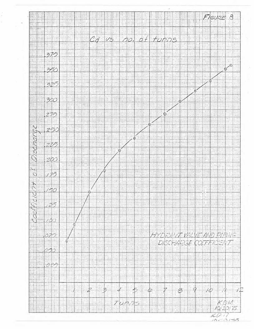
Discharge and differential head relationships were defined for gate openings from 1/2 to 11-3/8 turns, figures 5, 6, and 7. The slope of
N

the line Q2/AP is K and includes the coefficient of flow contraction for the valve disk. Coefficients of discharge for the valve and piping were computed by using the upstream pipe area for (nominal inside diameter 4.03 inches, (10 cm) 0.335 foot, 0.088 ft ). These are included in figure 8.
Shortest times of manual closure for the valve from various positions open were determined by three trials and two individuals. The measure-ment of closure was made by stopwatch with the valve discharging under maximum pressures of the piping system. The results of the average of the three trials appear in figure 9.
The results summarized here were previously given to the Tunnels and Pipelines Section for use in the design of the Spokane Indian Reservation sprinkle irrigation distribution system.
Copy to: 250 1530
3

Figure 1. Valve and Water Supply System.
Figure 2. Valve and location of piezometers for indicating and measuring pressures.


4


1 ]
11 I i
I}i- 1
7 7i 71
Ir
h 4 ... t } 1
7-1
{
JA
F ~ ~
1
-_ - -._.. . ..~.. w+.i ~ " -1t-, r • — +N _ tom_ _.
r`
F t
_ -
} .t
:+ }
4 T+ -
it +
i~
r 11~
}~
1AI ~.t
+ $
ty. ~ ~ X11-~ i {
{J1 FJt~
t: l~~ I~
' a ~ {. Jt
'1 .:
J J. ~ 1~
1 J ~
*t ~ 1i~ ~ ~•
}}J +i-7 ~+ +- •
~f , Y ~A—l} -~{{i
1
l~l: }1__ 1-
41 4 I - ;
4 1
I : 1 4 1 4 ~-4 -
4' A,1
1 4
44 1 1 1 , ; , fir7 1 7 777, 1 - I
L-LA
7
f
71 -- - - - - - - - - - . . . . . .
L 1 L L
iL-t-~- -
t4
r
T,
_7
T - - - - J-1
-:-+--7 -7
14
ut
I~T + T 7
E ~ E --f
4 T 7~
~4
4 LL
---- --- -77
L
-7--,
-7-
r4
rT
-4- - - - - - -
+ 71,11 77-7 7.
tt t
rt--, 4 4 .... . . . . . .
rtti-1
4-4
+ -4-
1 7 . i I , 1 1 ~_j 1
1
, 1 4 ~, +1 1, j
y t
I
T T--
i t

