operation, maintenance & installation ... - static-pt.com
TRANSCRIPT

i
10900 S.W. AVERY STREET - TUALATIN, OREGON 97062 U.S.A.email: [email protected] - 800-547-9696 - FAX: 503-692-6048
www.gaylordventilation.com
Rev 07
OPERATION, MAINTENANCE & INSTALLATION MANUAL
For“ELX” And “ELX-UVi” SERIES
VENTILATORS
GAYLORD INDUSTRIES

ii
All rights reserved. No part of this book may be reproduced, stored in a retriev-al system, or transmitted in any form by an electronic, mechanical, photocopy-ing, recording means or otherwise without prior written permission of Gaylord Industries.
©Copyright 2015, Gaylord Industries
The manufacturer reserves the right to modify the materials and specifications resulting from a continuing program of product improvement or the availability of new materials
Additional Copies $25.00 Each

iii
Gaylord Industries10900 SW Avery St. Tualatin, OR 97062
Office: 503.691.2010Toll Free: 800.547.9696
www.gaylordventilation.com
Gaylord Industries 10900 SW Avery Street Tualatin, OR 97062 www.gaylordventilation.com
To Our Customers:
Congratulations on your recent purchase of a Gaylord Model ELX Series Ventilator. We are proud to be able to provide you with a quality product that exemplifies our long standing dedication to quality engineering and manufacturing.
Your Gaylord Ventilator is assembled from some to the very finest components available and is designed for years of efficient, effective, and trouble-free operation. In addition, the product has undergone rigorous quality control inspections and testing prior to shipment.
If you have any questions, please contact us at [email protected] or by calling us toll free 800-547-9696. We are more than happy to help.
Sincerely,
Gaylord Industries

iv
Page iv
This Page Intentionally Left Blank

v
Page v
Table of ContentsChapter 1 – IntroductionIntroduction ..……………………………………………………………………………………………………………………. 1-1Model Description …………………………………………………………………………………………………………….. 1-2Model Number Explanation ………………………………………………………………………………………………. 1-3
Chapter 2 – Principles of Operation EL and ELX SeriesTurning on the Exhaust Fan ………....................................................................................... 2-1 Turning off the Exhaust Fan ………………….…….…………………………………………………………………… 2-2Cleaning the Ventilator ……………………………………………………………………………………………………… 2-3Fire Protection …………………………………………………………………………………………………………………… 2-3ELX-UVi SeriesTurning on the Exhaust Fan and UV System ……...................................................................... 2-5 Turning off the Exhaust Fan and UV System ..…………………………………………………………………….. 2-9Cleaning the Ventilator ……………………………………………………………………………………………………… 2-9Fire Protection …………………………………………………………………………………………………………………… 2-10Optional Balancer Dampers ………………………………………………………………………………………………. 2-12
Chapter 3 - Maintenance Operator Cleaning and Maintenance Instructions ……………................................................... 3-1UV System - Scheduled Preventive Maintenance ……………………………………………………………… 3-4Recommended Detergent for Cleaning ................................................................................. 3-7
Chapter 4 - TroubleshootingTrouble Shooting ……………………………………………………………………………………………………………… 4-1
Chapter 5 – Testing and Repair Measuring Airflow .................................................................................................................. 5-1Makeup Air Guidelines ……………………………………………………………………………………………………. 5-5Replacing UV Lamps ............................................................................................................... 5-7Replacing UV Lamp Sockets .................................................................................................. 5-10UV Ballast Box – Overview Ballast ........................................................................................ 5-14UV Ballast Box – Replacing Ballast Boards .............................................................................. 5-15UV Ballast Box – Replacing UV Ventilation Control Board ...................................................... 5-15UV Ballast Box – Replacing Ventilation Fan ............................................................................ 5-16UV Ballast Box – Pressure Switches - Overview..................................................................... 5-16UV Ballast Box – Setting Pressure Switches ............................................................................ 5-17UV Ballast Box – High Temperature Shutdown Controller ..................................................... 5-20

vi
Page vi
Table of Contents – Cont.
Chapter 6 - PartsParts - Ventilator ..................................................................................................................... 6-1Parts – UV Ventilator …………………………………………………………………………………………………………. 6-4Parts – UV Lamp Module …………………………………………………………………………………………………… 6-5Parts – UV Ballast Box ……………………………………………………………………………………………………….. 6-7
Chapter 7 – Wiring DiagramsWiring Diagrams ……………………………………………………………………………………………………………….. 7-1
AppendicesInstallation Requirements …………………………………………………………………………………………………. A-1 Ventilator Start-Up Inspection and Tests ………………………………………………………………………...... B-1Limited Warranty ...................................................................................................Inside Back Cover

1-1
Chapter 1 - Introduction, Page 1-1
Introduction
About this Technical ManualThe purpose of this manual is to provide the Operator, Maintenance and Service personnel instructions for operating, maintaining and troubleshooting the Gaylord Ventilator. Ventilators incorporating UV Systems, maintenance and repair must be performed by a trained and certified service company. This manual also includes information and guidance to contractors for the initial installation of the Ventilator.
The manual is divided into chapters for easy reference to a particular subject. The pages in the chapters are numbered with the chapter number then a dash and then the page number. So for example pages in Chapter 2 are numbered 2-1, 2-2, 2-3 etc. Figures and Tables are numbered in a similar manor. For example Figure 5-3-2 is on page 5-3 and is the second figure. Please keep your manual in a convenient location for so it can be accessed easily.
If you have any questions or concerns with the installation, operation, maintenance or service of your Gaylord Ventilator, please contact Gaylord Industries;
Web: www.gaylordventilation.comE-mail: [email protected] Phone: 503-691-2010 Toll Free: 800-547-9696
Safety It is important that the operator read Chapter 2, Principle of Operation, and Chapter 3, Maintenance, before operating the Ventilator for the first time. Particular attention should be given to all the Caution and Warning statements.
Related Technical Manuals1. ELX-UVi Series Ventilators are controlled by a Gaylord Command Center. The specific manual for
this control is titled Operation, Maintenance and Installation Manual for the Gaylord Command Center and Wash Control Cabinet.
2. ELX and ELX-UVi Series Ventilators installed in the United States all include a Gaylord Autostart Control. In some instances Ventilators installed outside the United States will include an Autostart Control. To determine if the Ventilator includes an Autostart Control refer to page 1-3 and the Nameplate mounted on the Ventilator. The specific manual for this control is titled Operation and Maintenance Manual for the Gaylord Autostart Control.
3. ELX and ELX-UVi Ventilators may include a Gaylord “Capture Wall” option. The specific manual for installation of this is titled Installation Manual – ELX Ventilators with Capture Wall.
Operation and Maintenance Manuals may be downloaded from the Gaylord website at www.gaylordventilation.com or may be obtained by calling Gaylord Industries.

1-2
Figure 1-2-2Model ELX-AB Series
Wall MountedBackshelf Style
Figure 1-2-4Model ELX-CL Series
Single Extractor Design for Single Island Arrangement
Chapter 1 – Introduction, Page 1-2
Model Description
OVERVIEWThe Gaylord Model EL Series Ventilator uses a Listed baffle filter and the ELX uses a Gaylord Model XGS high grease Extractor. The Model ELX-UVi Series includes the additional feature of an Ultraviolet Light System that removes up to 99% of the grease particulate.
The EL, ELX and ELX-UVi Ventilators come in many different models, some of which are illustrated below. Your Ventilator may appear slightly different as they may have been custom designed to fit the space and application.
Figure 1-2-1 Model ELX-BDL Series Wall Mounted Canopy Shown With Optional Capture Wall
Figure 1-2-3 Model ELX-BB Series Island Style for all Double Island Arrangements

1-3
Chapter 1 – Introduction, Page 1-3
Model Number Explanation
Model Number Sequence
Gaylord Ventilator model numbers are made up of an alphabetic prefix followed by a series of alphabetic and/or numeric suffixes to designate the style of ventilator and various options. Sequence of model numbers is as follows.
1._______ 2._______ 3._______ 4._______ 5._______ 6._______ 7._______ 8.________ 9.________
Series Damper Type
Style Front Lip Design
(Option)
Apron Design (If
Applicable)
Canopy Front Height
(Option)
Solid fuel AutoStart Hood Depth
Definition of Prefixes and Suffixes
1. SeriesEL ....................... Non water-wash ventilator with UL 1046 filters.ELX …………………. Non water wash ventilator incorporating XGS Extractors. ELX-UVi ............. Non water wash ventilator incorporating XGS Extractors and UV filtration.ELX-ENL …………. Non water wash ventilator incorporating XGS Extractors and UV filtration.
2. Damper TypeGBD ………………… Gaylord Balancing Damper. Has a mechanical balancing damper located at the duct
collar. (Standard)GFBD.................. Gaylord Fire Balancing Damper. Has an electric, thermostatically activated Fire/
Balancing damper located at the duct collar with back draft feature. 325°F thermostat standard.
GEBD ………………. Gaylord Electric Balancing Damper. Has an electric balancing damper located at the duct collar with back draft feature.
FDD .................... Weighted fuse link activated damper located at the duct collar. 280°F fuse link standard. ND …………………… No Damper.
3. Style Blank ……………… Wall mounted canopy style.
CL …………………… Island style for single line of cooking equipment using one extraction chamber (Light to Medium Duty only).BBC-CL …………… Island style for single line of equipment using one extraction chamber with one
common exhaust duct.BBC ………………… Island style for double line of cooking equipment using on one extraction chamber
and one common exhaust duct.BB …………………… Island style for double line of equipment using two extraction chambers and two
separate exhaust ducts

1-4
Chapter 1 – Introduction, Page 1-4
Model Number Explanation – Cont.
Definition of Prefixes and Suffixes – Cont.
4. Front Lip Design (Front lower edge of the hood)Blank ……………… Facetted front design with 6 inch return flange. (3 Break or greater at front lip) (CL models to have a maximum of 9”)S ......................... Square front with 6 inch “Super Capture” lip
5. Apron Design Designation
Blank ………………. Capture wall to be added below hood. A …………………….. Hood to have an apron, which will terminate at the bottom lower edge of the
canopy. (No interconnecting drains).UW …………………. Gaylord UDS to be incorporated into capture wall. (Mixed Intertek and UL listing
required).
6. Front Canopy Profile Option Blank ……………… Standard Profile - 30” or greater canopy height.MP …………………. Medium Profile - 24” to 30” front height. LP …………………… Low Profile - 12” to 23” front height. (Considerations for proper capture and contain need
to be considered with this option).
7. Solid Fuel Equipment (If Applicable – 700°F Applications only)Blank………………. Cooking equipment powered by sources other than the burning of wood.SPA………………… Hood use “XGS-SPA” Spark Arrestor Extractors – Intended applications that utilize
the burning of wood as a heat source.
8. AutoStart OptionBlank ................. Indicates the hood section does not have Autostart system as required by IMC. AS .................... Indicates the hood section has Autostart conforming with the IMC requirement.ASM ……………….. Indicates the hood is equipped with the second generation AutoStart system
conforming with the IMC requirement or the Demand Control Ventilation System complying with IMC IECC, Calif. Title 24, IGCC, and ASHRAE Std. 90.1 / 189.
ASM1………………. Indicates the hood is equipped with a DCV system for a single fan multi-hood application.
9. Hood Depth (Outside of Structural wall to front of hood canopy)(##) …………………. Value in inches to indicate the hood depth.

2-1
Chapter 2 – Principles of Operation, Page 2-1
EL and ELX Series
Turning on the Exhaust Fan
Caution: Always turn on the exhaust fan before turning on the cooking equipment.
Caution: The chemical fire extinguishing system may discharge if the exhaust fan is not on while the cooking equipment is on or still hot.
Caution: Never operate your Ventilator without the XGS Extractors or Grease Filters in place. Refer to Figure 2-1-1.
To operate the exhaust fan flip the fan switch to the ON position. The switch is typically mounted on a wall near the Ventilator or it may be mounted on the face of the Ventilator. Note 1: The EL and ELX Series Ventilator may be equipped with a Gaylord Electric Balancing Damper, designated “GEBD” in the Ventilator model number, or a Gaylord combination Fire Damper/Balancing Damper, designated “GFBD” in the model number. The Ventilator model number can be found on the Ventilator Nameplate (Refer to Figure 5-5-2 for a sample of the nameplate and to Page 2-12 for information on Balancing Dampers). If the Ventilator includes one of these dampers when the fan is started the damper moves from the closed to open position and it will take approximately 45 seconds for the exhaust to come up to 100%. Note 2: Typically EL, ELX and ELX-UVi Series Ventilators installed in the United States are equipped with a Gaylord Autostart Controller that automatically turns on the exhaust fan if the temperature at the sensors mounted in the canopy exceeds 90°F. (Refer to Figure 2-8-1). In some instances Ventilators installed outside the United States will include an Autostart Control. Inclusion of an Autostart Control is designated by the suffix “AS” in the model number. The Ventilator model number can be found on the Ventilator Nameplate (Refer page 5-5-2 for a sample of the Nameplate). Refer to the Operation, Maintenance and Installation Manual for the Gaylord Command Center for complete information on the Autostart Control.
Grease ExtractionGrease is extracted by either Listed Grease Filters or by the use of Gaylord Model XGS Extractors. Ventilators with Listed Grease Filters are designated EL Series and with Gaylord XGS Extractors they are designated ELX Series. The Gaylord Industries Patent Pending Model XGS Extractor is designed to deliver the absolute optimum in collection efficiency at the lowest possible pressure drop. The Extractors are ETL Recognized as part of the ELX Ventilator. They are constructed of corrosion resistant stainless steel.

2-2
Chapter 2 – Principles of Operation, Page 2-2
EL and ELX Series – Cont.
Turning on the Exhaust Fan – Cont.
Figure 2-2-1Grease Extraction
Turning Off the Exhaust Fan
Caution: Always turn off the cooking equipment and allow to cool before turning off the exhaust fan. The chemical fire extinguishing system may discharge if the cooking equipment is on or hot when the exhaust fan is off.
At the end of the cooking day, turn off the cooking equipment and allow to cool before turning off the exhaust fan. To turn off the exhaust fan flip the fan switch to the off positionNote 1: If the Ventilator includes a Gaylord Autostart Controller the exhaust fan will stay on if the temperature at the duct collar is above 90°F. Once the temperature drops below 90°F., the fan will continue to run for 60 minutes and then shut off.Note 2: If the Ventilator is equipped with a Gaylord Electric Balancing Damper, designated “GEBD” or a combination Gaylord Fire/Balancing Damper, designated “GFBD”, when the fan is turned off the damper will move from the open to the closed position, and remain closed until the exhaust fan is re-started. Closing the damper saves building energy by not allowing conditioned air from drafting up the exhaust duct, or in cold climates prevents cold air from coming down the duct and into the kitchen.
Autostart Sensor
Grease Laden Air
Balancing Damper
Gaylord ModelXGS Extractor
Grease Gutter
Grease Drawer
Light Fixture
2-3
Chapter 2 – Principles of Operation Page 2-3
EL and ELX Series – Cont.
Cleaning the Ventilator
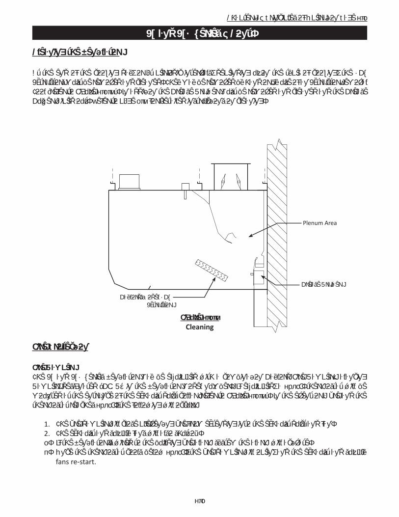
At the end of the cooking day, or at periodic intervals, depending upon the type of cooking, the XGS Extractors must be removed and cleaned. They may be removed by hand or by use of an Extractor Removal Tool (refer to Figure 2-3-1). In addition the Grease Drawer must be removed and cleaned and the Grease Gutter wiped out. Refer to page 3-1 for detailed instructions on cleaning.
Figure 2-3-1Cleaning
Fire Protection
Fire DamperThe EL and ELX Series Ventilator may be equipped with a combination Gaylord Fire Damper/Balancing Damper, designated “GFBD” in the Ventilator model number. If equipped, a 250°F. thermostat will be mounted at the entrance of the exhaust duct collar (refer to Figure 2-3-1). In the event or a fire and the thermostat reaches 250°F., the following will occur:
1. The fire damper will close preventing fire from extending into the exhaust duct and fan. 2. The exhaust and supply fans will also shut off. 3. If the Ventilator is wired to the building fire alarm system the alarm will activate. 4. Once the thermostat cools below 250°F., the fire damper will open, and the exhaust and supply
fans re-start.
Plenum Area
Grease Drawer
Gaylord Model XGS Extractor

2-4
Chapter 2 – Principles of Operation Page 2-4
EL and ELX Series – Cont.
Fire Protection – Cont.
Fire Extinguishing SystemsThe National Fire Protection Association Standard 96 (NFPA-96) and the International Fire Code (IFC) requires the use of a Fire Extinguishing System to cover the cooking surfaces, Ventilator exhaust plenums (the area behind the grease extractors), and the exhaust duct (Refer to Figure 2-4-1). Upon activation of the Fire Extinguishing System the follow will occur:
1. Fire extinguishing agent will discharge through the cooking equipment nozzles, the plenum nozzles and the duct nozzle(s).
2. The protected cooking equipment and possibly other cooking equipment will shut off. Refer to the above referenced codes for specific equipment that must shut off.
3. If the Fire Extinguishing System is wired to a building fire alarm system the alarm will activate.4. If the Fire Extinguishing System is wired to a building management system it will notify of a fire
condition. 5. The Fire Extinguishing System should be wired to the Gaylord fan control. If is the following will
occur: a) If the exhaust and supply fan were on the exhaust fan would stay on and the supply fan would
shut off. It the exhaust and supply fans were off, the exhaust fan would come on and the supply fan would stay off.
b) If the Ventilator is equipped with a Gaylord Electric Balancing Damper (model GEBD) or a Gaylord Fire/Balancing Damper (model GFBD) the damper will open.
6. After discharge, the Fire Extinguishing System must be recharged and certified by a fire system contractor before the cooking equipment can be turned back on.
For Operation and Maintenance of the Fire Extinguishing System, refer to the system manufacture’s Owner’s Manual.
Important: NFPA-96 requires inspection and certification of fire systems every 6 months.
Figure 2-4-1Fire Extinguishing System Discharge
When a Fire Extinguishing System Discharges, the Balancing Damper remains open. If equipped with an Electric Balancing Damper, Model GED, the damper remains open or opens if it was closed. If equipped with a Model GFBD Fire Damper, and the thermostat activates, the damper closes.
Fire Extinguishing System Detector
Fire Extinguishing System Plenum Nozzle
Fire Extinguishing SystemCooking Equipment Nozzles
Balancing DamperFire Extinguishing System Duct Nozzle

2-5
Chapter 2 – Principles of Operation Page 2-5
ELX-UVi Series
Ultraviolet Systems (UV)
OverviewVentilators incorporating UV Lamps are designated Model ELX-UVi Series Ventilators. UV Systems are used to remove a high percentage of grease that the Extractors cannot remove, offering many benefits to the owner/operator. The UV Lamps are mounted in a UV Module which slide into a track downstream (after) the XGS Extractors (refer to Figure 2-8-1). The electronics and ballasts for UV System are mounted in a UV Ballast Box which is located on the top of the Ventilator (refer to Figure 2-8-1). The ELX-UVi Ventilator is equipped with UV Status Lights to monitor the status of the UV System, and Safety Interlocks to protect operators from exposure to UV light (refer to Figure 2-7-1).
For proper UV operation, the Ventilators must be maintained in good working order. The UV system must be inspected periodically and the lamps replaced as necessary. The Ventilator, ductwork and exhaust fan must be inspected in accordance with NFPA-96 or local guidelines, though frequency of duct cleanings should be significantly reduced.
UV SafetyCaution: Exposure to UV light is harmful to skin and eyes. The ELX-UVi Ventilator is equipped with panels and Safety Interlocks to protect operators from direct exposure to UV light. All safety precautions called for is this manual must be followed to avoid the potential for harm to service personnel or operators. Refer to Page 3-3 for complete description of safety precautions.
Turning On the Exhaust Fan and UV System
Caution: Always turn on the exhaust fan before turning on the cooking equipment
Caution: The chemical fire extinguishing system may discharge if the exhaust fan is not on while the cooking equipment is on or still hot.
Caution: Never operate the Ventilator without the XGS extractors in place. Refer to Figure 2-5-2.
Operation of the exhaust fan and UV Lamps is controlled by the Gaylord Command Center (refer to Figure 2-6-1). To start the exhaust fan and turn on the UV Lamps push START FAN on the Command Center. The Command Center may be programmed to automatically start the exhaust fan at a specific time. Refer to the Operation, Maintenance and Installation Manual for the Gaylord Command Center for complete operating instructions.
Note 1: The UV Lamps will not come on unless all the XGS Extractors are in place as shown in Figure 2-5-2.Note 2: The UV Lamps will not come on unless all the UV Module Access Panels are closed and latched as shown in Figure 2-5-2.

2-6
Chapter 2 – Principles of Operation Page 2-6
ELX-UVi Series – Cont.
Turning On the Exhaust Fan and UV System – cont.
Note 3: ELX-UVi Series Ventilator may be equipped with a Gaylord Electric Balancing Damper, designated “GEBD” in the Ventilator model number, or a Gaylord combination Fire/Balancing Damper, designated “GFBD” in the model number. The Ventilator Model number can be found on the Ventilator Nameplate (Refer to page 2-12 information on Balancing Dampers and page 5-5-2 for a sample of the nameplate). If the Ventilator includes one of these dampers, when the fan is started the damper moves from the closed to the open position and it will take approximately 45 seconds for the exhaust air to come up to 100%.
Note 4: The ELX-UVi Series Ventilator may be equipped with a Gaylord Autostart Controller that automatically turns on the exhaust fan if the temperature at the exhaust duct collar exceeds 90° F. If the Ventilator does include Autostart, the Ventilator will include one or more sensors mounted in the canopy (Refer to Figure 2-5-2). Refer to the Gaylord AutoStart Technical Manual for Operation and Maintenance.
Figure 2-6-1Gaylord Command Center

2-7
Chapter 2 – Principles of Operation Page 2-7
ELX-UVi Series – Cont.
Turning On the Exhaust Fan and UV System – cont.
UV Status LightsEach Ventilator section contains a bank of UV Status Lights to monitor the UV System (refer to Figure 2-7-1). There are three colored lights, Green, Yellow and Blue. They indicate the system status as follows:1. Green On: The UV system is operating properly. 2. Yellow On: One or more UV Lamps are not operating.3. Blue On: One or more XGS Extractors are not in place and/or one or more UV Module Access Panels
are not latched properly, or the internal temperature of the Ballast Box has exceeded 118° F. and the High Temperature Shutdown Controller activated. During this mode the UV System is not operating, and is in a Uvi System Standby mode until the cause has been corrected.
Note: If either the Yellow or Blue light are on refer the Troubleshooting section of this manual beginning on page 4-1 for corrective action.
Figure 2-7-1UV Status Lights
Grease ExtractionGrease is removed from the exhaust air by combination of the Gaylord Model XGS Extractors and the UV Lamps (Refer to Figure 2-8-1). The hot contaminate-laden air rising from the cooking surface is drawn through the Extractors where a high percentage of the grease and other particulate are extracted from the airstream. As the air enters the Plenum chamber, the grease particles are exposed to the ultraviolet light which oxidizes the particles into a light gray powder which are deposited on the Lamps, the Plenum chamber and in the exhaust duct. Some powder may exhaust out the exhaust fan. The extracted liquid grease will drain down the Extractors and into the Grease Gutter which then drains to the Grease Collection Drawer. The sticky grease will remain in the Extractors until cleaned.
The Gaylord Industries Model XGS Extractor is designed to deliver the absolute optimum in collection efficiency at the lowest possible pressure drop. The Extractors are ETL Recognized as part of the ELXC-UVi Ventilator. They are constructed of corrosion resistant stainless steel.
UViSYSTEM
ON
UViLAMP
FAILURE
UViSYSTEM
STANDBY20385
SYSTEM STATUS
UVi VentilatorIntegrated DCV

2-8
Chapter 2 – Principles of Operation Page 2-8
ELX-UVi Series – Cont.
Turning On the Exhaust Fan and UV System – cont.
Figure 2-8-1Grease Extraction
Figure 2-8-2Model ELX-UVi Series Cutaway
Grease Drawer
OptionalRear Capture Wall
UV Lamp Module
Static Tap Cover
UV Module Access Doors
Access to Ballast Box
UV Status Lights
Autostart Sensor
Grease Laden Air
Balancing Damper
Gaylord ModelXGS Extractor
Grease Gutter
Grease Drawer
Ballast Box Accessible from Underside UV Lamps
UV Lamp Module

2-9
Chapter 2 – Principles of Operation Page 2-9
ELX-UVi Series – Cont.
Turning Off the Exhaust Fan and UV System
Caution: Always turn off the cooking equipment and allow to cool before turning off the exhaust fan. The chemical fire extinguishing system may discharge if the cooking equipment is on or hot when the exhaust fan is off.
At the end of the cooking day, turn off the cooking equipment and allow to cool before turning off the exhaust fan. To stop the exhaust fan and turn off the UV Lamps push STOP FAN on the Gaylord Command Center. The Command Center may be programmed to automatically turn off the exhaust fan at a specific time. Refer to the Operation, Maintenance and Installation Manual for the Gaylord Command Center for complete operating instructions. Note 1: If the Ventilator includes a Gaylord Autostart Controller the exhaust fan will stay on if the temperature at the duct collar is above 90° F. Once the temperature drops below 90° F., the fan will continue to run for 60 minutes and then shut off.
Note 2: If the Ventilator is equipped with a Gaylord Electric Balancing Damper, designated “GEBD” or a Gaylord combination Gaylord Fire/Balancing Damper, designated “GFBD”, when the fan is turned off the damper will move from the open to closed position and remain closed until the exhaust fan is re-started. Closing the damper saves building energy by not allowing conditioned air from drafting up the exhaust duct, or in cold climates preventing cold air from coming down the duct and into the kitchen.
Cleaning the Ventilator
At the end of the cooking day, or at periodic intervals, depending upon the type of cooking, the XGS Extractors must be removed and cleaned. They may be removed by hand or by use of an Extractor Removal Tool (Refer to Figure 2-9-1). In addition the Grease Drawer must be removed and cleaned and the Grease Gutter wiped out. The UV Lamps should be inspected weekly and cleaned if necessary. Refer to Page 3-1 for detailed instructions.
Figure 2-9-1Cleaning
Plenum Area
Grease DrawerGaylord Model XGS Extractor
Grease Gutter
UV LampsUV Lamp Module

2-10
Chapter 2 – Principles of Operation Page 2-10
ELX-UVi Series – Cont.
Fire Protection
Fire DamperThe ELX-UVi Series Ventilator may be equipped with a combination Gaylord Fire/Balancing Damper, designated “GFBD” in the Ventilator model number. If equipped, a 250°F. thermostat will be mounted at the entrance of the exhaust duct collar (Refer to Figure 2-11-1). In the event of a fire and if the thermostat reaches 250°F., the following will occur:
1. The fire damper will close preventing fire from extending into the exhaust duct and fan. 2. The exhaust and supply fans will shut off.3. The UV Lamps will shut off.4. If the Command Center is wired to a building fire alarm system the alarm will activate.5. If the Command Center is wired to a building management system it will notify of a fire condition. 6. Once the thermostat cools below 250°F., plus a 5 minute cool down, the exhaust and supply fans
can be re-started by pushing the START FAN on the Command Center.
Fire Extinguishing SystemsThe National Fire Protection Association Standard 96 (NFPA-96) and the International Fire Code (IFC) requires the use of a Fire Extinguishing System to cover the cooking surfaces, Ventilator exhaust plenums (the area behind the grease extractors), and the exhaust duct (Refer to Figure 2-11-1). Upon activation of the Fire Extinguishing System the follow will occur:
1. Fire extinguishing agent will discharge through the cooking equipment nozzles, the plenum nozzle(s) and the duct nozzle(s).
2. The protected cooking equipment and possibly other cooking equipment will shut off. Refer to the above referenced codes for specific equipment that must shut off.
3. If the Fire Extinguishing System is wired to a building fire alarm system the alarm will activate.4. If the Fire Extinguishing System is wired to a building management system it will notify of a fire
condition.5. The Fire Extinguishing System should be wired to the Gaylord Command Center. If it is the following
will occur: a) If the exhaust and supply fan were on the exhaust fan would stay on and the supply fan
would shut off. If the exhaust and supply fans were off, the exhaust fan would come on and the supply fan would stay off.
b) If the Ventilator is equipped with a Gaylord Electric Balancing Damper (model GEBD) or a Gaylord Fire/Balancing Damper (model GFBD) the damper will open.
6. After discharge, the Fire Extinguishing System must be recharged and certified by a fire system contractor before the cooking equipment can be turned back on.

2-11
Chapter 2 – Principles of Operation, Page 2-11
ELX-UVi Series – Cont.
Fire Protection – Cont.
Fire Extinguishing Systems – Cont.For Operation and Maintenance of the Fire Extinguishing System, refer to the system manufacturer’s Owner’s Manual.
Important: NFPA-96 requires inspection and certification of Fire Extinguishing Systems every 6 months.
Figure 2-11-1Fire Extinguishing System Discharge
*The illustration shows the Fire Extinguishing System discharging.
The National Fire Protection Association Standard 96 (NFPA-96) and the International Fire Code (IFC) re-quires the use of a Fire Extinguishing System to cover the cooking surfaces, ventilator exhaust plenum (the area behind the grease extractors), and the exhaust duct. For Operation and Maintenance of your Fire Extinguishing System, refer to the system manufacture’s Owner’s Manual.
Important: NFPA-96 requires inspection and certification of fire systems every 6 months.
When a Fire Extinguishing System Discharges, the Balancing Damper remains open. If equipped with an Electric Balancing Damper, Model GED, the damper remains open or opens if it was closed. If equipped with a Model GFBD Fire Damper, and the thermostat activates, the damper closes.
Fire Extinguishing SystemDetector
Fire Extinguishing SystemPlenum Nozzle
Fire Extinguishing SystemCooking Equipment Nozzles
Balancing Damper
Fire Extinguishing SystemDuct Nozzle

2-12
Chapter 2 – Principles of Operation, Page 2-12
Balancing Dampers
Balancing Dampers
Balancing Dampers Overview The ELXC and ELXC-UVi Series Ventilators, as a standard, come with one of three models of Gaylord Indus-tries Listed Balancing Dampers. Balancing dampers would typically be used when two or more Ventilators are connected to a common exhaust fan. The purpose of the balancing damper is to raise or lower the air-flow of each Ventilator to achieve the desired exhaust rate. One of the dampers models is a combination Fire/Balancing Damper. If the Ventilators include a Balancing Damper the suffix GBD, GEBD or GFBD will be included in the Ventilator model number shown on the Ventilator Nameplate. Refer to Figure 5-11-1 on page 5-11 for an example of the nameplate.
The three damper models available are as follows:1. Model GBD (Gaylord Balancing Damper) is a manually adjusted balancing damper with internal setting (refer to Figure 2-20-2). Adjustment is made by removing the Extractor under the exhaust duct collar and reaching up with a wrench to the Adjusting Nut. The nut is loosened, dampers manually adjusted and the Adjusting Nut retightened.
2. Model GEBD (Gaylord Electric Balancing Damper) is an electrically adjusted balancing damper (Refer to figure 2-20-1). Adjustment is made by use of a potentiometer, one for each damper, mounted in a junction box located in the roof of the Ventilator (Refer to figure 2-20-3). The GEBD is set up to automatically close upon shutting off the exhaust fan every night. This feature prevents conditioned air from exiting the build-ing through the Ventilator. In the event of a power failure the damper will automatically open.
3. Model GFBD (Gaylord Fire / Balancing Damper) is a combination thermostatically activated fire damper/electrically adjusted balancing damper. With this option one or more thermostats are mounted in the ex-haust duct collar of the Ventilator (Refer to Figure 2-6-2). The thermostats are factory set for 250°F., and in the event of a fire when the thermostat(s) reach 250°F., the damper will close to prevent fire from extend-ing into the ductwork and up to the exhaust fan. Adjustment for balancing of the system is made by use of a potentiometer, one for each damper, mounted in a junction box located in the roof of the Ventilator (Refer to figure 2-20-3). The GEBD is set up to automatically close upon shutting off the exhaust fan every night. This feature prevents conditioned air from exiting the building through the ventilator. In the event of a power failure the damper will automatically open.
AdjustmentThe adjustment of all the models relies on the internal dimension between the two blades called the Damper Set Dimension, “DSD” (Refer to Figure 2-20-2). The manipulation of this distance will balance the airflow between multiple section Ventilators. Refer to the Measuring Airflow section beginning on page 5-1 for more details.

2-13
Chapter 2 – Principles of Operation Page 2-13
Balancing Dampers – Cont.
Figure 2-13-1 Table T-2-13-1 Typical Model GEBD Electric Damper Correlation Chart Other Models Look Similar Except Without the Motor
Figure 2-13-2 Figure 2-13-4 Section View of Model GBD Potentiometer The Dampers and the DSD are the same for all Models
(%) OPEN DSD (in)
100
90
80
70
60
50
40
4-1/16
3-7/8
2-15/16
2-1/8
1-1/2
15/16
3/8

2-14
Chapter 2 – Principles of Operation, Page 2-14
This Page Intentionally Left Blank

3-1
Chapter 3 – Maintenance, Page 3-1
Cleaning and Maintenance
Operator Cleaning and Maintenance
OverviewTo maintain the Gaylord Ventilator in good working order, and to keep the system operating at optimum efficiency, preventive maintenance, using the following schedule should be performed.
Important Note: Ventilators incorporating UV Lamps require special maintenance as shown on Page 3-4. Some of the required maintenance on Ventilators with UV can be performed by the operator. However, direct exposure to UV light is hazardous to your skin and eyes and contact with live electrical components poses a significant risk of shock or death.
Daily Cleaning and MaintenanceAt the end of the each cooking day, or at periodic intervals, depending upon the type of cooking, the XGS Extractors and Grease Drawer must be removed and cleaned. The Grease Gutter should also be wiped out. CAUTION: Before proceeding with cleaning, check to see that the exhaust fan is shut off and the cooking equipment is cool. To clean proceed as follows: 1. Remove Extractors: CAUTION: Care should be taken when removing the Extractors, especially over
fryers. It is recommended that the cooking equipment be cooled down and the fryers be covered prior to removing the Extractors. They may be removed by hand or by use of an optional Extractor Removal Tool (Refer to Figure 3-2-1). To remove, lift up slightly on the Extractor and pull out from the bottom, then straight down.
2. The Extractors may be cleaned either by using a dishwasher or by soaking in a deep well sink using hot water with a degreasing detergent, then scrubbed and rinsed. Gaylord Formula G-510EF detergent is highly recommended for this application. Refer to Page 3-7 for details.
3. With the Extractors removed inspect the back wall and the underside of the exhaust plenum. If neces-sary clean with hot detergent water.
4. Wipe and clean the Grease Gutter.5. Remove and empty the Grease Drawer, clean and replace. 6. Replace the filters or Extractors. Note: Filters and Extractors must be installed with the openings run-
ning vertical as shown in Figure 3-2-2. Gaylord XGS Extractors have an arrow stamped on the face designating “UP”.
Additional Cleaning Instructions for UVi Series VentilatorsThe UV Lamps will develop a coating of dust, and sometimes debris that will have to be wiped away. The Lamps should be inspected weekly and cleaned when necessary. To clean proceed as follows:1. Remove all the Extractors.2. Reach up through the opening and carefully wipe each Lamp with a non abrasive wet cloth with mild
detergent. Remove all the dust, grease or other contaminants that may have collected on the Lamp. 3. Replace the Extractors.
Note: Failure to maintain the cleanliness of the Lamps will reduce the UV systems ability to reduce the build-up of grease and debris on the exhaust ducts and fans.

3-2
Chapter 3 – Maintenance, Page 3-2
Cleaning and Maintenance – Cont.Operator Cleaning and Maintenance – Cont.
Figure 3-2-1Cleaning
Figure 3-2-2Gaylord Model XGS Extractor
Light Fixture
Extractor Removal Tool
XGS ExtractorMust be washeddaily or as needed
Wipe outCondensateGutter dailyor as needed
Wipe down thelens to optimizeusable light atthe cookingsurface
(Access to Lamps)Clean UV Lampsas needed
Grease CollectionDrawer must beemptied daily or as needed

3-3
Chapter 3 – Maintenance, Page 3-3
Cleaning and Maintenance – Cont.
Operator Cleaning and Maintenance – Cont.
Code Required Inspection and Cleaning The National Fire Protection Association Standard NFPA-96 (Standard for Ventilation Control and Fire Pro-tection of Commercial Cooking Operations) requires that hoods (Ventilators), ducts and exhaust fans must be inspected by a properly trained, qualified and certified company or person(s) in accordance with the following table.
Table T-3-3-1
Upon inspection, if found to be contaminated with deposits from grease laden vapors, the entire exhaust system shall be cleaned by a properly trained, qualified, and certified company or person(s) acceptable to the authority having jurisdiction.
When a vent cleaning service is used, a certificate showing date of inspection or cleaning shall be main-tained on the premises. After cleaning is completed, the vent cleaning contractor shall place or display within the kitchen area a label indicating the date cleaned and the name of the servicing company. It shall also indicate any area not cleaned. CAUTION regarding pressure washing or steam cleaning: If the Ventilator includes a UV System the UV Modules must be removed prior to pressure washing or steam cleaning.

3-4
Chapter 3 - Maintenance, Page 3-4
UV System Scheduled Preventive Maintenance
CAUTION: Preventive maintenance and repairs made to the UV System as outlined on pages 3-3 through 3-5 MUST be performed by Gaylord Certified Service Agent. For a list of Gaylord Certified Service Agen-cies (CSA’s) visit www.gaylordventilation.com and go to “Service Agencies”.
WARNING: Certified Service Agent maintenance and repair warning. Do not defeat any Safety Interlocks during cleaning, maintenance and repair.
Safety RequirementsCaution: Exposure to UV light is harmful to skin and eyes. Before servicing or repairing any of the UV System read and perform the following safety requirements.
OverviewThe ELX-UVi Ventilator is equipped with light attenuation barriers and Safety Interlocks to protect opera-tors from direct exposure to UV light. All safety precautions called for in this manual must be followed to avoid the potential for harm to service personnel or operators.
As with many types of technology if it is not used properly and/or proper precautions are not taken there is the potential for injury or harm. This is especially true of UV light due to the fact that it does not physically hurt at the time of exposure. UV generated in these Ventilators is greater than what results from direct exposure to the sun. Under no circumstances is it acceptable to view the lighted lamps without proper eye protection or expose bare skin directly to the light. All safety precautions called for in this manual must be followed to avoid the potential for harm to service personnel and/or operators.
Personal Protective Equipment1. Eye protection that prevents 100% of UV light from being transmitted through the lens must be worn
at all times when replacing the UV Lamps on any ELX-UVi Ventilator that is energized and/or has the potential to be energized and expose personnel to UV light.
2. Whenever service work is performed it is recommended that long sleeve shirts and pants be worn to minimize the potential for inadvertent exposure of the skin to UV light.
Preventive MaintenanceThe following Preventive Maintenance items must be performed by a trained and qualified Certified Ser-vice Agency at a frequency shown on page 3-2, Table T-3-2-1, EXHAUST SYSTEM INSPECTION SCHEDULE. These tasks involve potential exposure to high doses of UV light and live electrical components. There is a risk of shock, injury and/or death from contact with live electrical components.
1. Testing UV Lamps and Ballasts (For these tests all XGS Extractors must be in place, the Extractor Access Doors closed and all UV Module Access Doors in place and latched.)
a. Turn on the exhaust fan at the Gaylord Command Center. The “UVi SYSTEM ON” green Status Light in each Ventilator Section should be on. In addition to the Status Lights on the Ventilator, the Gaylord Command Center should display text indicating the similar message as the Status Lights.

3-5
Chapter 3 - Maintenance, Page 3-5
UV System Scheduled Preventive Maintenance - Cont.
Testing UV Lamps and Ballasts - Cont.b. If the yellow “UVi LAMP FAILURE” Status Light is on it indicates that one or more of the UV Lamps
are not operating. To troubleshoot and replace a lamp refer to the Troubleshooting page 4-4, and Testing and Repair section of this manual beginning on page 5-13.
c. If the blue “UVi SYSTEM STANDBY” Status Light is on it indicates that one or more XGS Extractors are not in place and/or one or more UV Module Access Doors have not been closed properly or the internal temperature of the Ballast Box has exceeded 118° F. which activates the High Temperature Shutdown Controller. Refer to page 5-26 for troubleshooting and corrective action for the Tempera-ture Shutdown Controller.
Figure 3-5-1 UV Status Lights
2. Inspect and Clean UV Modules a. Turn off the exhaust fan at the Command Center. b. Open the UV Module Access Door(s) (refer to Figure 2-10-2). c. Disconnect the UV Module Lamp Ballast Connector. d. Remove the UV Module(s) from the Ventilator. (Caution: Care must be taken to keep the connector from hitting the lamps while removing the module.) e. Using a damp non abrasive cloth and mild detergent, wipe down the Lamps and Lamp Housing. Lamps should be free of all grease and debris. f. Carefully inspect the UV Module Access Door and replace the gasket as needed to ensure a good seal.
g. Reinstall the UV Module(s) being careful to not hit the Lamps. h. Reconnect the UV Module Lamp Ballast Connector. i. Close the UV Module Access Door(s).
3. Test Safety Interlocks for the XGS Extractors (Pressure Switches) (Caution: For the following tests Polycarbonate Safety Glasses must be worn.) a. Turn on the exhaust fan at the Command Center. The “UVi SYSTEM ON” green Status Light in each Ventilator Section should be on.
UViSYSTEM
ON
UViLAMP
FAILURE
UViSYSTEM
STANDBY20385
SYSTEM STATUS
UVi VentilatorIntegrated DCV

3-6
Chapter 3 - Maintenance, Page 3-6
UV System Scheduled Preventive Maintenance - Cont.
Test Safety Interlocks for the XGS Extractors (Pressure Switches) - Cont.b. Open the Extractor Access Door at the left end of the Ventilator remove one XGS Extractor. The blue
“UVi System Standby” Status Light should come on. If this action does not occur, immediately shut down the exhaust fan at the Command Center. Refer to the Troubleshooting section of this manual for corrective action. Repeat tests 3a and 3b for the right most XGS Extractor and again for the center XGS Extractor.
c. If there is more than one Ventilator section, repeat tests 3a and 3b for each section.
4. Test Safety Interlocks for the UV Module Access Panel (Pressure Switches) (Caution: For the following tests Polycarbonate Safety Glasses must be worn.) a. Turn on the exhaust fan at the Command Center. The “UV System On” green Status Light in each Ventilator Section should be on. b. Open one UV Module Access Door (refer to Figure 2-10-2). (Note: If there are two UV Module Access Doors always open the shortest door for the test). The blue “UVi System Standby” Status Light should come on. If this action does not occur, immediately shut down the exhaust fan at the Command Center, refer to the Trouble Shooting section beginning on page 4-4 for corrective action. c. If there is more than one Ventilator section, repeat the tests above, 4a and 4b, for each section.
5. Lamp ReplacementThe UV Lamps need to be replaced after 13,000 hours of use. After 13,000 hours the Lamps will still work but the performance of the Lamps decreases dramatically. The Gaylord Command Center has a built-in UV hours of operation clock. Refer to the Operation and Maintenance Manual for the Gaylord Command Center for complete operational instructions. If the Lamps have been in use over 13,000 hours they should be replaced. Refer to Page 5-13 of this manual for detailed instructions for replacing Lamps.

3-7
Chapter 3 – Maintenance, Page 3-7
Cleaning and Maintenance – Cont.
Detergent for Cleaning
FORMULA G-510EF is the only cleaner recommended by Gaylord Industries for use in cleaning Gaylord Model ELX Extractors. FORMULA G-510EF is a concentrated colloid cleaner specially formulated to remove the daily accumulation of grease in the Extractors and all other interior and exterior surfaces of the Ventila-tor. FORMULA G-510EF is safe for kitchen personnel and has a variety of uses.
FORMULA G-510EF Safety FORMULA G-510EF is registered with the U.S. EPA’s Design for the Environment Program (DfE) which seeks to promote the use of institutional cleaners and maintenance products with improved environmental and human health characteristics.
Cleaning the Gaylord ExtractorsThe Gaylord XGS Extractors may be cleaned by running through a dishwasher or by soaking in a deep well sink.
To soak proceed as follows:1. Place the Extractors in a deep well sink.2. Pour in 2-3 cups of FORMULA G-510EF.3. Fill sink with hot water until the water covers the Extractors.4. Let soak for 15-30 minutes.5. Scrub and rinse.6. Repeat if necessary.
FORMULA G-510EF for Cleaning the Ventilator ExteriorMix one part FORMULA G-510EF to twenty parts water in hand spray bottle. Spray on, let stand for a few minutes and wipe off.
FORMULA G-510EF for Other Cleaning JobsThe colloidal action of FORMULA G-510EF makes it a cleaner especially well-suited for use in kitchens. The colloids break up dirt and grease into millions of tiny particles that constantly repel each other. These particles cannot recombine or redeposit on a surface and are, therefore, easily washed away. FORMULA G-510EF contains no harsh chemicals, yet offers outstanding performance on the toughest cleaning jobs.
Use a mixture of one part FORMULA G-510EF to twenty parts water for:- VINYL/PLASTIC/WALLS...Removes dirt, grease, food deposits and fingerprints.- REFRIGERATORS...Removes dirt, spilled milk, blood, mildew and objectionable odors.- RESTROOMS...Add a disinfectant to clean all fixtures, walls, floors, etc.
Use a mixture of one part FORMULA G-510EF to five parts water for extremely heavy grease build-up, such as on the floor and on equipment around deep-fryers. Spray on, let set for a few minutes and rinse or wipe off. For extremely soiled areas, gentle agitation, followed by a soaking period, will result in more thorough cleaning. DON’T be afraid to experiment with FORMULA G-510EF because it contains no phos-phates, nitrates, enzymes, sulfates, suffocates or silicates.

3-8
Chapter 3 – Maintenance, Page 3-8
Limited Warranty2010 Products, Inc. warrants that Formula G-510EF will not cause cleansing agent damage to the rubber and synthet-ic parts of the injection pump (“O” rings, diaphragms, washers, tubing, and other such parts) used with The Gaylord Ventilator, Heat Reclaim Unit, or Pollution Control Equipment so long as used pursuant to its product instructions. 2010 Products, Inc. obligation under this warranty and any warranties implied by law shall be limited to repairing or replacing, at its option, any of said parts which 2010 Products, Inc. examination shall disclose to its satisfaction to have been damaged by the use of Formula G-510EF for the life of the detergent pumping system. This warranty shall not cover damages caused by any other detergent. The use of any other detergent shall void this warranty. All repairs and replacement parts under this warranty shall be F.O.B. 2010 Products, Inc. The owner shall pay the neces-sary freight and delivery charges; also removal and installation costs. Any federal, state or local taxes are also extra. Requests for repairs or replacement part should be made to 2010 Products, Inc., P.O. Box 7609, Salem, Oregon, 97303. This is the sole warranty with respect to FORMULA G510EF.
2010 Products, Inc. MAKES NO OTHER WARRANTY OF ANY KIND WHATSOEVER, EXPRESSED OR IMPLIED, AND ALL IMPLIED WARRANTIES OF MERCHANTABILITY AND FITNESS FOR A PARTICULAR PURPOSE WHICH EXCEED THE AFORESAID OBLIGATION ARE HEREBY DISCLAIMED AND EXCLUDED FROM THIS AGREEMENT. 2010 Products, Inc. SHALL NOT BE RESPONSIBLE FOR INCIDENTAL OR CONSEQUENTIAL DAMAGES RESULTING FROM A BREACH OF THIS WARRANTY.
IMPORTANTIf a cleansing agent other than FORMULA G-510EF is used with The Gaylord Ventilator injection pump and solenoid valves, it is recommended that a warranty similar to the above be obtained from the manu-facturer of said product, that the detergent has foaming properties similar to FORMULA G-510EF and that the above-referenced Warranty shall become null and void.
FORMULA G-510EF DistributorFor the name and address of the nearest FORMULA G-510EF distributor contact:
Gaylord Industries10900 SW Avery StreetTualatin, OR 97062E-mail: [email protected]: www.gaylordventilation.com
Phone: 800-547-9696

4-1
Chapter 4 – Troubleshooting, Page 4-1
Troubleshooting
Using the Troubleshooting Charts
The following Troubleshooting Charts are designed to easily find common problems, the probable cause and guidance for corrective action. In some cases the Corrective Action column will reference the Testing and Repair section of this manual for additional guidance and actions.

4-2
Chapter 4 – Troubleshooting, Page 4-2
Troubleshooting – Cont.

4-3
Chapter 4 – Troubleshooting, Page 4-3
Troubleshooting – Cont.

4-4
Chapter 4 – Troubleshooting, Page 4-4
Troubleshooting – Cont.

5-1
Chapter 5 – Testing and Repair, Page 5-1
Measuring Airflow
Measuring Airflow
Overview ELX and ELX-UVi Ventilators are factory engineered to operate at a specific exhaust volume, CFM (Cubic Feet per Minute), based on, primarily, the type of cooking appliance, and the exact model of the Ventila-tor. Smoke capture, grease extraction efficiency and heat removal are dependent upon the proper exhaust volume (Airflow) through the Ventilator. If the exhaust volume is below design, smoke, grease and heat may escape the confines of the Ventilator creating an uncomfortable kitchen for the operators. It will also reduce grease extraction efficiency of the XGS Extractors resulting in additional grease depositing in the duct system and exhaust fan. This can lead to sanitation problems and fire hazards if left uncorrected. If the exhaust volume is higher than design, more energy will be used to operate the exhaust fan, excessive noise levels will result, and grease can be pulled through the Extractors depositing in the duct and fan. Operating the Ventilator at higher or lower airflows than design will result in the entire kitchen ventilation system being of balance.
It is important that at initial installation of the Ventilator the exhaust volume is measured to verify that it meets design. It is also recommended that the exhaust volume be measured once every two or three years to insure that the exhaust fan is operating properly. The exhaust volume for each Ventilator section is stamped on the Ventilator Nameplate (refer to Figure 5-4-1 on page 5-4).
The Ventilator exhaust volume is determined by measuring the inlet velocity of the XGS Extractors and ap-plying the value to a formula converting velocity, in FPM, to an exhaust volume in CFM. This requires an Anemometer, and the recommended unit is a Pacer rotating vain Model DA40 or DA4000 Digital Anemom-eter. These instruments can be purchased from Gaylord Industries.
To measure the velocity and confirm the exhaust volume, proceed as follow:
Instructions1. For safety purposes turn off the cooking equipment and allow to cool.2. Confirm that all XGS Extractors are clean and in place.3. If model ELX-UVi Series, make sure all UV Module Access Doors and closed and latched.4. Turn on the exhaust fan.5. Attach the cable from the sensing head to the meter (refer to Figure 5-3-1 and 5-3-2).6. Attach the handle sections to the sensing head7. Beginning at the left Extractor, called extractor No. 1, place the sensing head against the face of the
Extractor, as shown in Figure 5-3-1.8. Using the 16 second averaging feature on the meter, slide the sensing head in a “Z” pattern as shown
on Figure 5-3-1, slowly, at a rate that would last roughly 16 seconds. If you reach the end of the “Z” pattern before the 16-Second interval has elapsed, continue moving the probe head back the other direction (without removing it) until the 16 second sample interval has expired.
9. At the end of 16 seconds an average velocity will appear on digital readout of the meter.10. Record the average velocity and identify as Extractor No. 1.11. Repeat the process for the remaining extractors, No. 2, 3 etc.12. Upon completing average velocity readings for each Extractor, add the readings together for a total.
Then divide this total by the number of Extractors. The result is called the Total Average Velocity (TAV).

5-2
Chapter 5 – Testing and Repair Page 5-2
Measuring Airflow Cont.
The Gaylord Model XGS Extractors come in two sizes, a nominal 11” H x 16” W, Model XGS-11, and a nominal 18” H x 16” W, Model XGS-18. It is necessary to know the area of an Extractor, in sq. ft., to determine the exhaust volume. Gaylord Industries has predetermined The Manufacture’s Corrected Area for each of the two sizes. They are as follows:
a. Size 11” H x 16” W = .75 sq. ft. Extractor Area (EA)b. Size 18” H x 16” W = 1.25 sq. ft. Extractor Area (EA)
13. To Determine the exhaust volume, CFM, for a Ventilator section use the following formula:
CFM = TAV x EA x NOE Where:
CFM = Cubic Feet per Minute (exhaust volume)TAV = Total Average Velocity (of the Extractors)
EA = Extractor Area (the area of each Extractor in sq. ft.) NOE = Number Of Extractors
Example:Assume you have seven 11” x 16” Extractors and the average velocity of each Extractor is:394+368+392+402+399+379+388 = 2722 divided by 7 = 389 (rounded up).This is your TAV (Total Average Velocity).
CFM = TAV x EA x NOECFM = 389 x .75 x 7CFM = 2042
14. Compare the measured CFM with the CFM stamped on the Ventilator Nameplate (refer to Figure 5-4-1). The acceptable range is 0% low and 10% high. If the CFM is not within acceptable range then cor-rective action must be taken to bring the exhaust volume within design. Typically low or high exhaust volumes are caused by one of the following:
a) If the Ventilator has a balancing damper and if the Determined CFM is low, the Balancing Damper needs to be opened slightly. If the Determined CFM is high the Balancing Damper needs to be closed slightly. Refer to page 2-12 for specific instructions on adjusting the dampers.
b) Important Note: Keep in mind that as one damper is adjusted it will affect the exhaust volume in the remaining Ventilator sections so making minor adjustments, and coming back and retaking static readings is highly recommend. Continue either opening or closing the Balancing Damper until the measured CFM is at or close to the desired CFM stamped on the label.
c) The exhaust fan may not be operating properly. Refer to the Troubleshooting section, page 4-1 for possible problems and corrective action.

5-3
Chapter 5 – Testing and Repair Page 5-3
Measuring Airflow – Cont.
Sensing Head
Figure 5-3-1Sensing Head Placement
Figure 5-3-2Anemometer

5-4
Chapter 5 – Testing and Repair Page 5-4
Measuring Airflow – Cont.
Figure 5-4-1Ventilator Nameplate
The minimum required exhaust volume can be found stamped on on the ETL nameplate located on each hood section. The minimum values do not always correspond to the design requirements for each hood section.
Total Exhaust CFM Here

5-5
Chapter 5 – Testing and Repair Page 5-5
Makeup Air Guidelines
Capture PerformanceAll Gaylord Ventilators are factory engineered to operate at a specific exhaust volume, CFM (Cubic Feet per Minute), based on, primarily, the type of cooking appliance, and the exact model of the Ventilator. Capture performance is based on two primary functions, 1) the ventilator is exhausting the engineered CFM and 2) the makeup air is being introduced correctly. Makeup air introduced incorrectly will typically result in smoke and heat loss into the kitchen, even if the Ventilator is operating at the engineered CFM. Makeup air is typically brought into the kitchen space through ceiling diffusers or through a combination of Gaylord Makeup Air Plenum Boxes, Model PBW, (refer to Figure 5-6-1) and ceiling diffusers.
Capture and Performance GuaranteeGaylord Industries provides the following guarantee for all Gaylord Ventilators:
Gaylord Capture Performance GuaranteeGaylord Industries warrants the Capture Performance of the Ventilator, only if the Exhaust Air Volumes are correct, per the Exhaust Volume Guidelines as stated below, and the Makeup Air Volumes are correct and delivered correctly per the Makeup Air Delivery Guidelines as stated below.
Exhaust Volume Guidelines1. The amount of exhaust CFM through the Ventilator shall be between 100% and 110% of the values
stamped on the Ventilator Nameplate for each Ventilator section.
Makeup Air Delivery GuidelinesA. With Gaylord Plenum Boxes and ceiling diffusers.
1. Gaylord Plenum Boxes Model PBW, shall be located immediately in front of the Ventilator, a mini-mum of 18” from the lower lip of the Ventilator to the discharge surface of the PlenumBox. (Refer to Figures 5-6-1 and 5-6-2).
2. The amount of makeup air delivered through the Gaylord Plenum Box(s) shall be between 90% and 100% of the values shown on Gaylord Submittal Drawings.
3. The amount of makeup air through the Plenum Boxes shall not exceed 60% of the exhaust volume of the Ventilator.
4. Ceiling diffusers shall be at least 6’-0” away from all sides of the Ventilator and the outlet velocity at the diffusers shall not exceed 150 Feet per Minute (FPM).
B. With ceiling diffusers only.1. Ceiling diffusers shall be at least 15’-0” away from all sides of the Ventilator and the outlet
velocity at the diffusers shall not exceed 300 Feet per Minute (FPM) (Refer to Figure 5-6-1).C. Additional Requirements.
1. The maximum velocity of the makeup air from diffusers, transfer air diffusers, or any other type of diffusers shall not be greater than 75 FPM on all open sides of the lower edge of the Ventilator.
2. Cross drafts from pass through windows, hallways, or other openings shall not exceed 50 FPM.3. All forms of makeup air, such as ceiling diffusers, transfer air diffusers, and Plenum Boxes must
be evenly distributed around each Ventilator to prevent unequal pressurization.4. Kitchen pressurization shall not exceed -0.02” W.G. relative to the dining or adjacent spaces as
stated in NFPA-96 and ASHRAE Standard 154.5. For more information on acceptable methods of makeup air delivery reference ASHRAE
Standard 154.

5-6
Chapter 5 – Testing and Repair Page 5-6
Makeup Air Guidelines – Cont.
Following these guidelines will result in proper cap- ture and containment at the Ventilator and enact the Gaylord Capture Performance Guarantee. If jobsite conditions cannot accommodate these guidelines, consult Gaylord Industries for alternative design.
Figure 5-6-1 Plan View - Typical Kitchen
Figure 5-6-2Section View - Typical Kitchen

5-7
Chapter 5 – Testing and Repair Page 5-7
Replacing UV Lamps
OverviewThe UV Lamp Modules come in two lengths, a nominal 3’-0” and 5’-0”. The length and number of modules is dependent on the length of the Ventilator section (refer to Table T-5-7-1). There are six lamps in each module.
Table T-5-7-1
Replacing UV Lamps
DANGER: Replacing UV Lamps as outlined on this page MUST be performed by a Gaylord Certified Ser-vice Agent. For a list of Gaylord Certified Service Agencies (CSA’s) visit www.gaylordusa.com and go to “Service Agencies”.
SAFETY PRECAUTIONSTasks involved to replace UV Lamps involve potential exposure to high doses of UV light and live electrical components. There is a risk of serious injury to skin and eyes from UV light. There is a risk of shock, injury, and /or death from live electrical components.
Personal Protective Equipment
1. Eye protection that prevents 100% of UV light being transmitted through the lens must be worn at all times when replacing the UV Lamps on any ELXC-UVi Ventilator that is energized and/or has the poten-tial to be energized and expose personnel to UV light.
2. Whenever service work is performed it is recommended that long sleeve shirts and pants be worn to minimize the potential for inadvertent exposure of the skin to UV light.
Chapter 5, Page 5-13
TESTING AND REPAIR
Replacing UV Lamps Overview The UV Lamp Modules come in two lengths, a nominal 3’-0” and 5’-0”. The length and number of modules is dependent on the length of the Ventilator section (refer to Table T-5-13-1). The number of lamps used is dependent on the type of cooking equipment the Ventilator is covering.
Table T-5-13-1
Replacing UV Lamps DANGER: Replacing UV Lamps as outlined on this page MUST be performed by a Gaylord Certified Service Agent. For a list of Gaylord Certified Service Agencies (CSA’s) visit www.gaylordusa.com and go “Service Agencies”. SAFETY PRECAUTIONS Tasks involved to replace UV Lamps involve potential exposure to high doses of UV light and live electrical components. There is a risk of serious injury to skin and eyes from UV light. There is a risk of shock, injury, and /or death from live electrical components. Personal Protective Equipment 1. Eye protection that prevents 100% of UV light being transmitted through the lens must be worn at
all times when replacing the UV Lamps on any ELXC-UV Ventilator that is energized and/or has the potential to be energized and expose personnel to UV light.
2. Whenever service work is performed it is recommended that long sleeve shirts and pants be worn to minimize the potential for inadvertent exposure of the skin to UV light.
Number of UV Lamp Modules Active
Ventilator Length
Number of 3’-0”
Modules
Number of 5’-0”
Modules 4’-0” – 6’-5” 1 0 6’-6” – 7’-5” 0 1 7’-6” – 9’-11” 2 0 10’-0” – 12’-5” 1 1 12’-6” – 16’-0” 0 2

5-8
Chapter 5 – Testing and Repair Page 5-8
Replacing UV Lamps - Cont.
Instructions for Replacing UV LampsTo replace UV lamps carefully use the following step by step instructions.
1. Turn off all power to the Gaylord Command Center.2. Turn off all circuits that supply power to the UV Lamps.3. Open the UV Module Access Door (Refer to Figure 5-9-1).4. Disconnect the Lamp / Ballast Connector cable by twisting the connector counter clockwise (refer to
Figure 5-13-1).5. Carefully slide out the UV Module (refer to Figure 5-9-1).6. Referring to Figure 5-9-2, remove the two bolts pc #9, washer’s pc #8, Module End Cap pc #7, and Sili-
con Gasket pc #6 from each end of the module.7. Slide off each UV Lamp Sockets, pc #5, from the Lamps at each end of the Module.
• Each UV Lamp Socket should be labeled 1 to 6.• Lamp #1 is at the front of the Ventilator when the UV Module is installed.• Lamp #6 is at the back of the Ventilator when the UV Module is installed.• Be sure to re-label the Lamp Sockets if necessary.
8. Lubricate the Lamps around the Grommets, pc # 2, on each end of the UV Lamp with a small amount of Formula G-510EF or similar detergent.
9. CAREFULLY slide the UV Lamp out one end.10. Inspect the Grommets around the Lamps.
• Replace any Grommet that show cracks, or any other damage.11. Check all UV Lamp Sockets and wires for damage.
• Replace Light Sockets if the socket or wire show damage.12. Before installing, lubricate each of the new UV Lamps with a small amount of Formula G-510EF or
similar detergent.13. Slide in all the new UV Lamps.14. Reconnect all the UV Lamp Sockets to the appropriate numbered Lamp, #1 through #6.15. Check the Silicon Gaskets for cracks or deterioration. Replace if needed.16. Re-install the Silicon Gaskets, Module End Caps, Washers and bolts, and torque the bolts to 20 in – lbs.17. Slide the UV Module back into the Ventilator.18. Reconnect the Lamp / Ballast Connector Cable.19. Check the UV Module Access Door Gasket for cracks or deterioration. Replace if needed.20. Close the UV Module Access Door.21. Close all Extractor Access Doors.22. Turn on all circuits that supply power to the UV Lamps.23. Turn on power to the Gaylord Command Center.24. Check for proper operation of the UV Lamps and Pressure Switches following the Test Lamps and Bal-
lasts instructions beginning on page 3-4.

5-9
Chapter 5 – Testing and Repair Page 5-9
Replacing UV Lamps - Cont.
Figure 5-9-1
Figure 5-9-2UV Module
(Exploded View)
1/4 - 20 BoltWasher
Module End Cap
Silicon Gasket
UV Lamp Socket (Long Wire End-Wire Not Illustrated)
Grommet
WashersNuts Front of UV Lamp Module
Conduit Tube
Pinned Receptacle
Rear of UV Lamp Module
Lamp #1Lamp #2Lamp #3Lamp #4Lamp #5Lamp #6
9
108
25
67
8
11
UV Module Access Door
Access to Ballast Box
UV Status Lights AutoStart SensorStatic Tap Opening
UV Lamp Module
UV LampsExtractor
Extractor Access Door

5-10
Chapter 5 – Testing and Repair Page 5-10
Replacing UV Lamp Sockets
OverviewIf the UV Lamp Socket or wire connected to it is damaged they must be replaced. The UV Lamp Socket and the wire come as one piece. They are not available individually. There are two methods of replacing UV Lamp Sockets, the Individual Method or the Wiring Harness Method. Use the following directions for replacing:
DANGER: Replacing UV Lamp Sockets as outlined on the following pages MUST be performed by a Gaylord Certified Service Agent. For a list of Gaylord Certified Service Agencies (CSA’s) visitwww.gaylordventilation.com and go to “Service Agencies” or call Gaylord Industries at 503-691-2010.
Safety PrecautionsCaution: Tasks involved in replacing UV Lamp Sockets involve potential exposure to high doses of UV light and live electrical components. There is a risk of serious injury to skin and eyes from UV light. There is a risk of shock, injury, and /or death from contact with live electrical components.
Personal Protective Equipment1. Eye protection that prevents 100% of UV light being transmitted through the lens must be worn at all
times when working on UV Lamp Modules on any ELXC-UV Ventilator that is energized and/or has the potential to be energized and expose personnel to UV light.
2. Whenever service work is performed it is recommended that long sleeve shirts and pants be worn to minimize the potential for inadvertent exposure of the skin to UV light.
Instructions for Replacing UV Lamp Sockets – Individual MethodTo replace UV Lamp Sockets carefully use the following step by step instructions.
1. Turn off all power to the Gaylord Command Center.2. Turn off all circuits that supply power to the UV Lamps.3. Open the UV Module Access Door (Refer to Figure 5-9-1).4. Disconnect the Lamp / Ballast Connector Cable by twisting the connector counter clockwise (refer to
Figure 5-13-1).5. Carefully slide out the UV Module and place on a work bench.6. Referring to Figure 5-13-3, remove the two bolts pc #9, washers, pc #8, Module End Cap pc #7, and the
Silicon Gasket, pc #6, from each end of the module.7. Slide off each UV Lamp Socket, pc #5, from the Lamps at each end of the Module.8. Remove the four screws that hold the base of the Pinned Receptacle, Figure 5-13-3 pc #11, to the Lamp
Module and pull the base away from the Module until the wires are exposed.9. The UV Lamp Sockets are numbered 1 through 6. The wire from each UV Lamp Socket is wired back to
the Pinned Receptacle and connected to a pin labeled A through N (refer to Figure 5-11-1). There are two UV Lamp Sockets with wire per Lamp. One is called the UV Lamp Socket Long Wire, the one that runs to the opposite end of the Pinned Receptacle. The other is called the UV Lamp Socket Short Wire, the one that is at the end with the Pinned Receptacle. Identify the wire by number to be replaced.
10. Cut the identified wire at the Pinned Receptacle. CAUTION: Do not pull the UV Lamp Long Wire out at this time. It is needed to pull the new Lamp Socket through the conduit tube.

5-11
Chapter 5 – Testing and Repair Page 5-11
Replacing UV Lamp Sockets - Cont.
Instructions for Replacing UV Lamp Sockets – Individual Method – Cont.
1. Slide off the UL Lamp Sockets from the Lamp and remove the UV Lamp Socket Short Wire. CAUTION: Do not pull the UV Lamp Long Wire at this time. It is needed to pull the new Lamp Socket through the conduit.
2. Using a Pin Removal Tool, Gaylord Part Number 20415, push the associated pin out of the base of the Pinned Receptacle.
3. All Lamp Sockets come with a 76” wire length so each has to be cut to match the one being replaced.4. Cut the correct length wire, and at the end opposite the Lamp Socket, strip back 1/4” of the insulation.
Solder on the pin that is provided.5. Push the soldered wire pin into the base of the Pinned Socket, for both the Short and Long Wire, at the
appropriate letter socket. Refer to Table T-5-11-1 and Figure 5-11-1.6. Re-install the Pinned Socket base.7. Replace the UV Socket Long Wire by tying the end of the cut Long Wire to the socket end of the new UV
Socket Long Wire and pull it through the conduit wire way (Refer to Figure 5-13-3).8. Slide the UV Sockets onto the Lamp at both ends.9. Check the Silicon Gaskets for cracks or deterioration. Replace if needed.10. Re-install the Silicon Gaskets, Module End Caps, Washers and bolts, and torque the bolts to 20 in – lbs.11. Slide the UV Module back into the Ventilator.12. Reconnect the Lamp / Ballast Connector Cable.13. Check the UV Module Access Door Gasket for cracks or deterioration. Replace if needed.14. Close the UV Module Access Door.15. Turn on all circuits that supply power to the UV Lamps.16. Turn on power to the Gaylord Command Center.17. Check for proper operation of the UV Lamps and Pressure Switches following the Test Lamps and Bal-
lasts instructions beginning on page 3-4.
Table 5-11-1 Figure 5-11-1 Pinned Receptacle
Pin Letter
Left End Long Wire Lamp Sock
Right
End
ShA 1B 2C 3D 4E 5F 6G 4H 3I 2J 1K 5LMN 6
Pin Letter A B C D E F G H I J K L M N
Left End Long Wire Lamp
Socket #4 3 2 1 5 6
Right End Short Wire
Lamp Socket # 1 2 3 4 5 6
Table T-5-18-1
Not
Use
d
Gro
und
Wir
e
Connection Points From Pinned Receptacle to UV Lamp Sockets
Table T-5-18-1
Alternate
Connection Points From
Pinned Receptacle to UV
Ground WireNot Used

5-12
Chapter 5 – Testing and Repair Page 5-12
Replacing UV Lamp Sockets - Cont.
Instructions for Replacing UV Lamp Sockets – Wiring Harness Method
DANGER: Replacing UV Lamp Sockets as outlined on this page MUST be performed by a Gaylord Certified Service Agent. For a list of Gaylord Certified Service Agencies (CSA’s) visit www.gaylordventilation.com and go to “Service Agencies” or call Gaylord Industries at 503-691-2010.
Safety PrecautionsCaution: Tasks involved in replacing UV Lamp Sockets involve potential exposure to high doses of UV light and live electrical components. There is a risk of serious injury to skin and eyes from UV light. There is a risk of shock, injury, and /or death from contact with live electrical components.
Personal Protective Equipment
1. Eye protection that prevents 100% of UV light being transmitted through the lens must be worn at all times when replacing the UV Lamps on any ELX-UVi Ventilator that is energized and/or has the poten-tial to be energized and expose personnel to UV light.
2. Whenever service work is performed it is recommended that long sleeve shirts and pants be worn to minimize the potential for inadvertent exposure of the skin to UVC light.
Overview The UV Lamp Sockets Wiring Harness comes with 6 Lamp Sockets Long Wire and 6 Lamp Sockets Short Wire connected to the base of a Pinned Receptacle.
InstructionsTo replace all UV Lamp Sockets with a wiring harness carefully use the following step by step instructions.
1. Turn off all power to the Gaylord Command Center.2. Turn off all circuits that supply power to the UV Lamps.3. Open the UV Module Access Door.4. Disconnect the Lamp / Ballast Connector Cable by twisting the connector counter clockwise (refer to
Figure 5-13-1).5. Carefully slide out the UV Module and place on a work bench.6. Referring to Figure 5-13-3, Remove the two bolts pc #9, washers, pc #8, Module End Cap pc #7, and the
Silicon Gasket, pc #6, from each end of the module.7. Slide off each UV Light Socket, pc #5, from the Lamps at each end of the Module.8. Remove the four screws that hold the base of the Pinned Receptacle, pc #11, to the Lamp Module and
pull the base away from the Module until the wires are exposed.9. The UV Lamp Sockets are numbered 1 through 6. The wire from each UV Lamp Socket is wired back to
the Pinned Receptacle and connected to a pin labeled A through N (refer to Figure 5-13-2). There are two UV Lamp Sockets with wire per Lamp. One is called the UV Lamp Socket Long Wire, the one that runs to the opposite end of the Pinned Receptacle. The other is called the UV Lamp Socket Short Wire, the one that is at the end with the Pinned Receptacle. Cut all the wires at the Pinned Receptacle. CAU-TION: Do not pull the UV Lamp Long Wire at this time. It is needed to pull the new Lamp Socket Long Wire through the conduit tube.

5-13
Chapter 5 – Testing and Repair Page 5-13
Replacing UV Lamp Sockets - Cont.
1. Remove all the UV Lamp Socket Short Wire. CAUTION: Do not pull the UV Lamp Long Wire at this time. It is needed to pull the new Lamp Socket through the conduit.
2. Pull all but one of the UV Lamp Socket Long Wire.3. Install the new Pinned Socket base.4. Replace the group of UV Socket Long Wires by tying the end of the one remaining Long Wire to the
socket ends of the new group of UV Socket Long Wires and pull them through the conduit tube.5. Slide all the UV Sockets onto the Lamp pins at both ends being careful to match the number on the UV
Sockets to the number on the Module.6. Check the Module End Caps Silicon Gaskets for cracks or deterioration. Replace if needed.7. Re-install the Module End Caps with gasket, washers and bolts, and torque the bolts to 20 in – lbs.8. Slide the UV Module back into the Ventilator.9. Reconnect the Lamp / Ballast Connector Cable.10. Check the UV Module Access Door Gasket for cracks or deterioration. Replace if needed.11. Close the UV Module Access Door.12. Turn on all circuits that supply power to the UV Lamps.13. Turn on power to the Gaylord Command Center.14. Check for proper operation of the UV Lamps and Pressure Switches following the Test Lamps and
Ballasts instructions beginning on page 3-4.
Figure 5-13-1 Figure 5-13-2 Lamp / Ballast Connector Pinned Receptacle
Figure 5-13-3 UV Module (Exploded View)
1/4 - 20 BoltWasher
Module End Cap
Silicon Gasket
UV Lamp Socket (Long Wire End-Wire Not Illustrated)
Grommet
WashersNuts Front of UV Lamp Module
Conduit Tube
Pinned Receptacle
Rear of UV Lamp Module
Lamp #1Lamp #2Lamp #3Lamp #4Lamp #5Lamp #6
9
108
25
67
8
11

5-14
Chapter 5 – Testing and Repair Page 5-14
UV Ballast Box
OverviewThere is one UV Ballast Box for each Ventilator section. The UV Ballast Box contains the Ballasts and other electrical components necessary to operate the UV System (Refer to Figure 5-21-2). A list of all the components and their part numbers are shown on Page 6-7 and 6-8. To replace any of the components proceed as follows:
BallastThe Ballasts are called Ballast Boards (refer to Figures 5-21-2 and 5-22-1). The number of Ballasts Boards is dependent upon the number of UV Lamp Modules, one or two. One Ballast Board serves two UV Lamps. So, for example, if the Ventilator has two UV Lamp Modules then there would be a total of 12 Lamps and therefore six Ballasts Boards. The Ballasts Boards are mounted on Ballast Board Plates (Refer to Figure 5-21-2). If the Ventilator has two UV Lamp Modules there are two Ballast Board Plates, one mounted in front of the other. The Front Ballast Board Plate always serves the left UV Lamp Module and the Rear Ballast Board always serves the right UV Lamp Module. So, for example if the Ventilator has two Lamp Modules the Front Ballast Board Plate would have two Ballast Boards and the Rear Ballast Board Plate would also have two Ballast Boards.
The Ballast Boards are numbered 1, 2 and 3. Ballast Board number 1 serves Lamp number 1 and 2, Ballast Board number 2 serves Lamp number 3 and 4, and ballast Board number 3 serves Lamp number 5 and 6. (Refer to Table T-5-14-1).
Table T-5-14-1
There are two Green and two Red Status Lights on a Ballast Board, one set for each Lamp (refer to Figure 5-19-2). The Status Lights are numbered Lamp 1 through 6 to correspond with the Lamp number. A Green light indicates the Lamp is operational and a Red light indicates the Lamp is not operational and must be replaced. If both lights are out then the Ballast Board is faulty and it must be replaced.
1 12 23 34 45 56 6
Serves Lamp #
Serves Ballast
Board #
1
2
3
1
2
3
Ballast Board / Lamp ChartLeft UV Module
Front Ballast Board Plate
Right UV Module Rear Ballast Board
PlateServes Ballast
Board #
Table 5-21-1
Serves Lamp #

5-15
Chapter 5 – Testing and Repair Page 5-15
UV Ballast Box - Cont.
Replacing Ballast BoardsTo replace the Ballast Board proceed as follows (refer to Figure 5-21-2 and 5-22-1):
Caution: Turn off all power to the Command Center and to the UV Ballast Box. There is a risk of shock, injury, and /or death from contact with live electrical components.
1. Turn off all power to the Gaylord Command Center.2. Turn off all circuits that supply power to the UV Lamps.3. Remove the UV Ballast Box Access Cover.4. Unplug the Ballast Board power.5. Remove the two screws that hold the Front Ballast Board Plate. Remove the Rear Ballast Board Plate
if necessary.6. Remove all wires from the terminal blocks. Label if necessary.7. In three corners of the Ballast Board are plastic standoff retainers and the fourth corner is a screw.
Using a screwdriver push in the retainer tab on the plastic standoff while pulling up on the Ballast Board. Remove the one screw.
8. Install a new Ballast Board, wire the plug in harness to the terminal block, mount the Ballast Board to the Ballast Board Plate and remount, and plug the harness back in.
9. Inspect the UV Ballast Box Access Cover Gasket for cracks and deterioration and replace if necessary.10. Replace the Access Cover. 11. Turn on all circuits that supply power to the UV Lamps.12. Turn on power to the Gaylord Command Center.13. Check to make sure both Green lights are on.
Replacing UV Ventilation Control BoardThe UV Ventilation Control Board (Refer to Figures 5-19-2 and 5-22-2) monitors all the Safety Interlock Pressure Switches. If the Safety Interlock Pressure Switches are in a normal operational condition, a signal is sent to activate the Ballast Contactor allowing the UV System to operate. If a Safety Interlock Pressure Switch detects a problem, such as an Extractor Access Door or UV Module Access Panel being left open, a signal is sent to deactivate the Ballast Contactor which turns off the UV System. The UV Ventilation Control Board has three main components, the UV Monitoring Board, the Ballast Contactor and the Status Light Relay. If it is determined that any of these three components are defective replace as follows:
Caution: Turn off all power to the Command Center and to the UV Ballast Box. There is a risk of shock, injury, and /or death from live electrical components.
1. Turn off all power to the Gaylord Command Center.2. Turn off all circuits that supply power to the UV Lamps.3. Remove the UV Ballast Box Access Cover.4. Uncouple the wire plug that interties the UV Ventilation Control Board to the Ballast Boards.5. Unplug the wires leading to the Pressure Switches.6. Remove all wires from the appropriate terminal blocks. Label if necessary.

5-16
Chapter 5 – Testing and Repair Page 5-16co UV Ballast Box - Cont.
Replacing UV Ventilation Control Board – Cont.
1. Remove the 2 screws that hold the Din Rail and remove the entire assembly.2. Loosen and slide off the end retainer (Refer to Figure 5-22-2).3. Slide off the components as required.4. Slide on the new component and tighten the end retainer.5. Reinstall the Din Rail and reconnect all the wires.6. Inspect the UV Ballast Box Access Box Access Cover Gasket for cracks and deterioration and replace if
necessary.7. Replace the Access Cover. 8. Turn on all circuits that supply power to the UV Lamps.9. Turn on power to the Gaylord Command Center.
Replacing Ventilation FanThe Ventilation Fan removes the heat generated by all the electrical components. It is on, typically, whenever the exhaust fan is on. If the Ventilation Fan is not pushing enough air, pull out the mesh filter, clean and replace. If the Ventilation Fan is determined to be defective, replace it as follows (Refer to Figure 5-21-2).Caution: Turn off all power to the Command Center and to the UV Ballast Box. There is a risk of shock, injury, and /or death from live electrical components.
1. Turn off all power to the Gaylord Command Center.2. Turn off all circuits that supply power to the UV Lamps.3. Remove the UV Ballast Box Access Cover.4. Disconnect the wires from the terminal block.5. Remove the 4 screws from the holding bracket and remove the fan.6. Install a new fan in the reverse order.7. Inspect the UV Ballast Box Access Box Access Cover Gasket for cracks and deterioration and replace if
necessary.8. Replace Access Cover.9. Turn on all circuits that supply power to the UV Lamps.10. Turn on power to the Gaylord Command Center.
Pressure SwitchesThere are two Pressure Switches used as the Safety Interlocks that monitor if all the XGS Extractors are in place, and if the UV Module Access Panels are closed and latched. If one or more XGS Extractors are missing and / or one or more UV Module Access Panels are not in place the Pressure Switches will sense a pressure drop and shut down the UV System.
A 1/8“copper tube runs from a Static Pressure Tap in the Ventilator plenum into the Ballast Box. The copper tube is then connected to a clear vinyl tube which in turn is connected to the Pressure Switch. The vinyl tube is called a Vacuum Release Tube and has a small hole midway in the tube to allow trapped pressure

5-17
Chapter 5 – Testing and Repair Page 5-17
UV Ballast Box - Cont.
Pressure Switches - Cont.
that may have been caused by the static tap plugging with grease, to bleed off. This safety feature will automatically shut off the UV System if the static tap becomes plugged. Caution: If the vinyl tube needs replacing always use Gaylord Industries Vacuum Release Tube (refer to Parts 6-8).
The Pressure Switches must be set prior to the initial operation of the Ventilator, and after the exhaust volume has been verified in accordance with the Measuring Airflow section on pages 5-1 through 5-4. To set the Pressure Switches proceed as follows (Refer to Figure 5-19-1). Caution: Testing the Pressure Switches must be performed by Gaylord Certified Service Agent. For a list of Gaylord Certified Service Agencies (CSA’s) visit www.gaylordventilation.com and go to “Service Agencies”.
Caution: The Pressure Switches are located in the Ballast Box which is only accessable from the underside of the Ventilator. Therefore before you get started setting the Pressure Switches be sure to provide yourself secure means to the equipment in order to gain access to the critical components contained in the ELX Ballast Box.
Caution: To set the Pressure Switches the exhaust fan must be on and therefore the Ballast Box will have live electrical components. Be extremely careful not to make contact with live electrical components. It is recommended that gloves be worn while adjusting the switches. There is a risk of shock, injury, and/or death from contact with live electrical components.
CAUTION: Verify that the SPADE CONNECTORS ARE IN PLACE PRIOR TO ANY ADJUSTING as illustrated in Figure 5-19-1. If Not proceed to “Spade Connector not in Place Procedure”.
PRIOR to Starting (Site Conditions): The Kitchen Exhaust system is to be fully balanced. All Doors and windows to be closed and sealed consistent with the future operation of the kitchen. Make up air and transfer air systems are to be activated and running during this procedure. Cooking Equipment is to be OFF. Kitchen Ambient Temperatures are to be between 750F and 850F. Kitchens running outside these temperatures may not be set correctly. A follow up must be conducted with the kitchen after it is in operation to verify the operations of the UV system and its interlocks.
Setting the Pressure Switches
1. Confirm the Ventilators are properly balanced and verify that if so equipped the Demand Control Sys-tem is running at 100%.2. Install all XGS Extractors.3. Remove the UV Ballast Box Access Cover located on the roof of the canopy for each Ventilator section. A 7/16” Nut Driver will be needed. (Gently push up the inner cover, then slide over and down to remove).4. Use a (SHORT) Philips screwdriver to remove the Cover Screws holding the Plastic Covers on both Pressure Switches, as shown in Figure 5-19-1.5. Once the covers are removed, verify spade connectors are in place as shown in Figure 5-19-1. CAUTION:***RISK OF SHOCK*** If the spade connectors shown are not in place turn off the power immediately. Follow the “Spade Connector not in Place Procedure” shown at the end of this section.

5-18
Chapter 5 – Testing and Repair Page 5-18
UV Ballast Box - Cont.
Setting the Pressure Switches - Cont.
6. With gloves on and Ventilator running at 100%, turn the Adjustment Dial, as shown in Figure 5-19-1 on Pressure Switch “A”, COUNTER CLOCKWISE until you hear a click, and the corresponding green LED lights illuminate on the Ventilation Control Board, shown in Figure 5-19-2. Then turn the Adjustment Dial Pressure Switch “B” COUNTER CLOCKWISE until you hear a “click”. The green LED lights on the Ventilation Control Board will illuminate, and the green UVi SYSTEM ON light, on the Ventilator, will also come on. (NOTE: Both Pressure Switches need to be on for the UV system to turn on. LED lights will always come on when the pressure switch closes)7. Once the UV Lamps are activated, all green LED lights on the Ventilation Control Board are illuminated, and the green UVi SYSTEM ON light on the Ventilator is illuminated, gently turn Pressure Switch Adjustment Dial on Pressure Switch “A”, CLOCKWISE until the UV Lamps deactivate, then back again slowly COUNTER CLOCKWISE until the UV system comes back on. Repeat this process for Pressure Switch “B”. The Pressure Switches are now set.8. Replace the pressure switch covers.9. Briefly secure the Ballast Box Access Cover. It must be in place to maintain proper pressurization in the Ballast Box enclosure.10. Test the System: Remove the XGS Extractor(s) at one end of the Ventilator. The UVi SYSTEM ON light(s) must DEACTIVATE and the UV Lamps shut off shut off immediately, less than one second. If they do not, place the XGS Extractors back in the Ventilator and repeat steps 3 through 9.11. Repeat this process until the UVi SYSTEM ON lights remains illuminated, and the UV Lamps stay on. 12. Once the system is functioning properly, completely secure the Ballast Box Access Cover, and move on to the next Ventilator section. Repeat as needed.
Spade Connector not in Place Procedure: 1. Shut off Power to the UV Ventilator. Note: There are two breakers to deactivate. a) 208/240 UV module power. b) 120 VAC Power to the Command Center. 2. Verify power is shut down by checking voltage on terminal 6U on the Ventilation Control Board. Also check terminals L3/L4. Voltage for both needs to be 0. Refer to Figure 5-19-2 3. Place a Spade Terminal on the live Terminal shown in Figure 5-19-1, for both Pressure Switches as needed. Return to “Setting the Pressure Switches”.

5-19
Chapter 5 – Testing and Repair Page 5-19
UV Ballast Box - Cont.
Figure 5-19-1Pressure Switches
CAUTION: VERIFY SPADE CONNECTOR IS IN PLACE PRIOR TO ADJUSTMENT. IF IT IS NOT, FOLLOW “SPADE CONNECTOR NOT IN PLACE” PROCEDURE ON PAGE 5-18
Figure 5-19-2Ventilation Control Board
COVER SCREW
SPADE CONNECTOR
ADJUSTMENT DIALS
A B
GREEN LED LIGHTSTERMINALS L3 AND L4
TERMINAL 6U

5-20
Chapter 5 – Testing and Repair Page 5-20
UV Ballast Box - Cont.
High Temperature Shutdown ControllerA High Temperature Shutdown Controller is mounted in the Ballast Box to monitor the internal temperature of the box and to shut down the UV System if the temperature in the Ballast Box exceeds 118°F. (Refer to Figure 5-21-2). Temperatures above 118°F may cause the Ballast Box components to fail. Activation of the High Temperature Shutdown Controller (Refer to Figure 5-21-1) will shut off the UV system, turn on the Blue UVi System Standby status light mounted on the Ventilator, and the Gaylord Command Center will display text indicating a similar message as the status light. The exhaust fan will remain on. The High Temperature Shutdown Controller will typically activate for the following reasons:
1. The Ventilation Fan has failed. To replace the Ventilator Fan follow the instructions on page 5-16.2. The Mesh Filter on the fan inlet is clogged or the inlet is blocked by building insulation or other material. Corrective action: Clean or replace the Mesh Filter and/or remove any building insulation from the inlet.3. The louvers at the opposite end of the Ventilation Fan are blocked by building insulation or other material. Corrective action: Remove any building insulation from the inlet of the louvers.4. Building insulation has been placed over the top of the Ballast Box. Corrective action: Cut a rectangular opening in the insulation, the size of the Ballast box, and slide it down around the sides of the box. Tape the insulation down so it will not interfere with the openings.5. The cooking equipment under the Ventilator is in a “runaway” condition and operating too hot. Corrective action: Check with owner/equipment operator to see if cooking equipment is operating properly. If not, it must be serviced.
Important Note: The above conditions must be corrected or a UV Ballast failure will follow.
Checking the High Temperature Shutdown Controller ProgramThe High Temperature Shutdown comes programmed from the Gaylord factory and should never need to be reprogrammed. To check the program, use the following instructions:
1. Push the “START FAN” button on the Command Center. Check to insure that the Green UVi System On status light is on.2. Confirm controller is showing current ambient temperature (Refer to Figure 5-21-1).3. Briefly push Set, “SP” will appear.4. Press Set a second time, then release. “118” will appear. If it does not, the control is either faulty or needs to be reprogrammed. Consult a Gaylord Service Agency or call Gaylord Industries for instructions.

5-21
Chapter 5 – Testing and Repair Page 5-21
UV Ballast Box - Cont.
Figure 5-21-1High Temperature
Shutdown Controller
Figure 5-21-2UV Ballast Box
PRESSURE SWITCHES
VENTILATIONCONTROL BOARD
BALLAST BOARD
VENTILATION FAN
MESH FILTER
HIGH TEMPERATURE SHUTDOWN CONTROLLER

5-22
Chapter 5 – Testing and Repair Page 5-22
UV Ballast Box - Cont.
Figure 5-22-1Ballast Board
Figure 5-22-2Ventilation Control Board
Figure 5-22-3Safety Interlock Pressure Switch

6-1
PC No.
DescriptionGaylord Part No.
Illustration
1 Extractor - Model XGS - Size 11" H x 16" L 76044
2Extractor - Model XG-SPA (Spark Arrester) Size 11" H x 16" L 76045
3 Extractor - Model XGS-18-Size 18" H x 16" L 30514
4Extractor - Model XGS-18-SPA (Spark Arrestor) Size 18" H x 16" L
76043
5 Extractor Removal Tool 76046
6Grease Drawer with Handle - for Ventilators with Rear Wall Design
76040
7Grease Drawer with Handle - for Ventilators with Apron Design (no rear wall)
76041
8 Grease Drawer Handle
Parts - Ventilator
9 100 Watt Surface Mounted Light Lens 10119
1012 x 12 Recessed Incandescent Light Lens and Retainer
13211
1148" Long Recessed Fluorescent Light Lens and Retainer
10112
1236" Long Recessed Fluorescent Light Lens and Retainer
10111
LED Lamp for 48" Fluorescent Lights
for 36" Fluorescent Lights 20326
for 48" Fluorescent Lights 20327
13
Chapter 6 – Parts, Page 6-1
Ventilator Parts

6-2
Chapter 6 – Parts, Page 6-2
Ventilator Parts - Cont.
PC No.
DescriptionGaylord Part No.
Illustration
1Ventilator Exhaust Duct Collar Thermostat. 12" Long, NC Contacts, Factory set at 250 degrees F.
18465
2Ventilator Exhaust Duct Collar Thermostat. 15" Long, NC Contacts, Factory set at 250 degrees F. Note: For ELX-BBC Series Only.
18466
3 Static Tap 19545
Table T-6-2-1
Parts - Ventilator - Cont.
4Damper Control Motor 24 Volts) For GFBD and GEBD Model Dampers
19176
5 Spray Nozzle - For Extractor Wash 20329
6Spray Nozzle - For Plenum Wash (Pack of 2)
10303

6-3
Chapter 6 – Parts, Page 6-3
Ventilator Parts - Cont.
PC No.
DescriptionGaylord Part No.
Illustration
1 Autostart Sensor (new style) 20319
2 Autostart Sensor (old style) 76004
3 Autostart Controller complete with box 20317
4Autostart Controller only (No box provided)
20318
Table T-6-3-1Parts - Ventilator - Cont.
4(No box provided)
20318
6-3
6-3

6-4
Chapter 6 – Parts, Page 6-4
UV Ventilator Parts
PC No.
DescriptionGaylord Part No.
Illustration
1 UV Module - 3'-0", 6 Lamps (Includes Lamps) 76057
2 UV Module - 5'-0", 6 Lamps (Includes Lamps) 76058
3 3'-0" Lamp (single lamp) 20269
4 5'-0" Lamp (single lamp) 20270
5 UV Modual / Ballast Connector 76069
Table T-6-4-1
Parts - UV Ventilator
6 UV Status Lamp - Green 19725
7 UV Status Lamp - Yellow 19724
8 UV Status Lamp - Blue 19723
Gasket for UV Module Access Doors3'-0" Module 201705'-0" Module 20171
Lift & Turn Latch for UV Module Access Door 1935110
9
UV Module / Ballast Connector 20138

6-5
Chapter 6 – Parts, Page 6-5
UV Lamp Module Parts
Pc. No.
DescriptionQty. per Module
Gaylord Part No.
Illustration
1 1/2-13 x 1-1/2 Round Head Slot Screw 4 202892 ELX UV Lamp Cover Washer 8 202883 1/2-13 Hex Nut 4 202904 1/4-20 x 3-1/4 Hex Head Bolt 4 202845 1/4 Bonded SS Sealing Washer 8 20140
6 Silicon Gasket for Lamp Module End Cap 2 20299
7 UV Lamp Grommmet 12 19312
8 Heraeus UV Lamp
3'-0" Lamp (single lamp each) * 20269
5'-0" Lamp (single lamp each) * 20270
9 Panel Mount Pinned Receptical 20-27 1 20283
* Lamps sold individually
Table T-6-5-1
Parts - UV Lamp Module
Not Illustrated
6-4
Chapter 6 - Parts
UV Ventilator Parts
PC No.
DescriptionGaylord Part No.
Illustration
1 UV Module - 3'-0", 6 Lamps (Includes Lamps) 76057
2 UV Module - 5'-0", 6 Lamps (Includes Lamps) 76058
3 3'-0" Lamp (single lamp) 20269
4 5'-0" Lamp (single lamp) 20270
5 UV Modual / Ballast Connector 76069
Table T-6-4
Parts - UV Ventilator
6 UV Status Lamp - Green 19726
7 UV Status Lamp - Yellow 19724
8 UV Status Lamp - Red 19723
Gasket for UV Module Access Panels3'-0" Module 201705'-0" Module 20171
9
UV Lamp Grommet

6-6
Chapter 6 – Parts, Page 6-6
UV Lamp Module Parts - Cont.
Pc. No.
DescriptionGaylord Part No.
Illustration
Pin Extractor Tool for Pinned Receptical 20415
Pin Insertion Tool for Pinned Receptical 20414
2 Pins, Male, for UV Pinned Receptical 20416 Not Illustrated
3Single Pin UV Lamp Socket with 76" Halogen Free Wire and Connector Pin Shipped Loose.
19799
Complete Single Pin UV Lamp Socket wiring harness for 6 Lamp Modules. Includes the short and long Lamp Socket wires pre-wired
Parts - UV Lamp Module - cont.
Table T-6-6-1
1
short and long Lamp Socket wires pre-wired to the base of the Panel Mount Base Receptical.For 3'-0" Lamp Module 20412For 5'-0" Lamp Module 20413
5 UV Module - 3'-0", 6 Lamp (Includes Lamps) 76057
6 UV Module - 5'-0", 6 Lamp (Includes Lamps) 76058
4

6-7
Chapter 6 – Parts, Page 6-7
UV Ballast Box Parts
PC No.
DescriptionGaylord Part No.
Illustration
1 Ventilation Fan 19430
UV Ballast Board (complete)
For 3'-0" 6 Lamp Module 76063
For 5'-0" 6 Lamp Module 76065
Parts - UV Ballast Box
Table T-6-7-1
2
3 UV Ventilation Control Board 20100
4 Contactor 30529
22472UV Ballast Board (complete)
UV Monitoring Board with Contactor - Complete Mounted on Din Rail
76029

6-8
Chapter 6 – Parts, Page 6-8
UV Ballast Box Parts - Cont.
PC No.
DescriptionGaylord Part No.
Illustration
1 Relay 30833
2 UV Pressure Switch 20146
3 Pressure Switch Pressure Release Tube 20174 NOT ILLUSTRATED
Parts - UV Ballast Box - Cont.Table T-6-8
Gasket for UV Ballast Box Access Cover11-1/2" x 20" 2017316" x 16" 20172
1/4-20 Chrome Acorn Nut for UV Ballast Box Cover 10766
Bonded Sealing Washer 20140
4
5
Vacuum Release Tube
20489

7-1
120 VOLT HOLDINGCOIL IN MAGNETICSTARTER SWITCH
H N
FANSWITCH
ELECTRICAL SERVICEBY OTHERS
H N
LIGHTSWITCH
LIGHTFIXTURES
INTERCONNECTINGW IRINGBETWEEN HOOD SECTIONSBY ELECTRICAL CONTRACTOR
ELECTRICAL SERVICEBY OTHERS
Chapter 7 – Wiring Diagrams, Page 7-1
The Wiring Diagrams on the following pages are typical for various applications and may not represent your installation. Always refer to the Gaylord submittal drawings for the actual Wiring Diagrams for your installation.
Figure 7-1-1Typical Exhaust Fan WiringFor Ventilators Without UV
or Electric Dampers
Figure 7-1-2Typical Light Fixture Wiring
ELECTRICAL SERVICEBY OTHERS
ELECTRICAL SERVICEBY OTHERS

7-2
Figure 7-2-1Wiring Diagram
with GFBD
9
GFBD INTERNAL WIRING / SINGLE SECTION
FIGURE 16GFBD/GEBD Internal Wiring Diagram
Figure 7-2-2Wiring Diagram
with GEBD
Chapter 7 – Wiring Diagrams, Page 7-2
GFBD & GEBD INTERNAL WIRING / SINGLE SECTION

7-310
GFBD EXTERNAL WIRING / MULTIPLE SECTION
FIGURE 16BGFBD External Wiring Diagram
Figure 7-3-1GFBD External Wiring Diagram
Chapter 7 – Wiring Diagrams, Page 7-3
GFBD External Wiring / Multiple Section

7-4
ELX GBD OR ND / NO UV WIRING DIAGRAM
Figure 7-4-1
Chapter 7 – Wiring Diagrams, Page 7-4
ELX GBD or ND / No UV

7-5
ELX GFBD / NO UV WIRING DIAGRAM
Figure 7-5-1
Chapter 7 – Wiring Diagrams, Page 7-5
ELX GFBD / No UV

7-6
ELX-UV GBD / ND WIRING DIAGRAM
Figure 7-6-1
Chapter 7 – Wiring Diagrams, Page 7-6
ELX-UV-GBD-ND

7-7
ELX-UV GFBD WIRING DIAGRAM
Figure 7-7-1
Chapter 7 – Wiring Diagrams, Page 7-7
ELX-UV-GFBD

7-8
Chapter 7 – Wiring Diagrams, Page 7-8
This Page Intentionally Left Blank

A-1
Appendix A, Page A-1
Installation Requirements
Code ComplianceVentilators must be installed to comply with all applicable codes.1. Ventilator to be installed in accordance with NFPA-96, Standard for Ventilation Control and Fire
Protection of Commercial Cooking Operations, the IMC, International Mechanical Code, and all other local applicable codes.
2. All plumbing and electrical must comply the applicable codes. 3. Contractors must review applicable codes with code authorities before approving drawings for
fabrication. 4. Special attention must be given to code regulations relative to clearances from surrounding combustible
constructions (walls, ceilings, etc.).
PermitsIMPORTANT NOTE: Most building departments require the Ventilator (hood) permit separate from any other general building permit. In addition if a Fire Extinguishing System is involved a separate permit from the Ventilator permit is typically required. The Ventilator permit is typically obtained through the plan review department and the Fire Extinguishing System permit through the fire prevention bureau. The installing contractor must check with local building departments for their requirements, and to obtain necessary permits.
Ventilator ListingThe Gaylord Model ELX and ELX-UVi Series Ventilators are listed to UL 710 and Recognized by ETL. Any modification made to the Ventilator at the jobsite will void the listing.
Hanging the VentilatorUse the following guidelines for hanging the Gaylord Ventilator:1. The maximum section length of a Gaylord Ventilator is 16’-0”. Ventilators longer than 16”-0” are made
up of multiple sections. 2. The weight of the Ventilator is shown on the Gaylord Submittal Drawings.3. Each Ventilator section has a full length Rear Mounting Bracket at the rear for bolting to the wall and/
or hanging from the overhead. There are two other full length hanging brackets; the Middle Mounting Bracket and the Front Mounting Bracket for hanging from the overhead (refer to Figure A-2-1). All three Hanging Brackets have pre-punched holes centers for hanging from the overhead. Hanging rods to be supplied by the Ventilator installer. If the rear bracket is used for bolting to the wall the holes must be drilled by the installing contractor at a support point in the wall. Refer to Table T-A-1-1 for minimum number of mounting points.
4. It is recommended that the number of hanging rods used be no less than the recommend minimum as shown on Table T-A-2-1.
5. The Ventilator(s) must be installed at the distance from the finish floor and the minimum side overhang dimension from the end of the Ventilator to the cooking equipment as shown on the Gaylord Submittal Drawings.
6. When there is a continuous Ventilator made up of two or more sections it is recommended that each Ventilator section is hung individually. Angles are provided at the top of the sections for bolting together. The bolts are provided by Gaylord. Hem strips and bolts are provided by Gaylord for joining the Ventilators on the underside where visible.

A-2
REAR MOUNTING BRACKET
MIDDLE MOUNTING BRACKET
FRONT MOUNTING BRACKET
Appendix A, Page A-2
Installation Requirements – Cont.
1. Caution: When installing Ventilators incorporating a UV system, ELX-UVi Series, do not cover the UV Ballast Box, mounted on top of the Ventilator, with building insulation. Covering the Ballast Box inlet and outlet ventilation openings will cause the box to overheat which could result in failure of electrical components. Covering the Ballast Box with insulation will void the Ventilator and the Warranty.
Table T-A-2-1
Figure A-2-1Ventilator Hanging Point

A-3
Appendix A, Page A-3
Installation Requirements – Cont.
DuctworkGrease exhaust ducts must be installed in compliance with NFPA-96, IMC and other applicable codes. Use the following guidelines when installing the exhaust ducts: 1. Exhaust ducts must be constructed of 16 gauge steel or 18 gauge stainless steel.2. Exhaust ducts must be constructed with continuous external welds and be grease and water tight.3. Exhaust duct must be continuously welded to the Ventilator duct collar.4. All elbows should be sweeping 90’s. Right angle turns or elbows less than sweeping may negatively
impact the operation of the Ventilator. 5. All horizontal ducts should slope towards the Ventilator and/or towards an approved sump. Amount of
slope must be in accordance with the IMC.
ElectricalRefer to the wiring diagrams on the Gaylord Submittal Drawings for specific wiring interconnections.1. If Ventilator is provided with a built-in fan switch, provide a separate 120 volt or 220 volt circuit to the
fan switch J-box mounted on top of the Ventilator. The fan switch is rated for 20 amps, 277 volts, 1 h.p. at 120 volts, 2 h.p. at 220 volts, 16 amps max.
2. If the Ventilator is provided with a Gaylord Command Center, provide a 120 volt 20 amp service to the control. Optional voltage, when specified, 220 volt 50/60 Hz.
3. If the Ventilator is built in multiple sections, and if they contain electric dampers, or thermostats, reconnect the flex conduit provided at the section breaks. The electrical contractor is responsible for making these connections.
4. If the Ventilator is provided with light fixtures, provide a separate 120 volt lighting circuit to one of the light J-box on the top of the Ventilator. Ventilator may be equipped with built-in light switch.
5. Ventilators built in multiple sections have a flex conduit at the section breaks for interconnecting the light fixture J-boxes. The electrical contractor is responsible for making these connections.
Additional Electrical for Ventilators with a UV SystemRefer to the wiring diagrams on the Gaylord Submittal Drawings for specific wiring interconnections.1. The UV Lamp Modules are shipped with the Ventilator. They are installed and tested by a Gaylord
Certified Representative at the time of initial Start Up and Demonstration. They must be stored in a clean, dry environment where they will not be damaged by lift trucks, falling objects, etc.
2. Provide 208–250 VAC, 50/60HZ, Single Phase, 20AMP service to the marked j-box on the top of each Ventilator section to power the UV Lamp Modules.
3. Ventilators built in no more than two sections have a flex conduit to interconnect the two UV Ballast Boxes. The electrical contractor is responsible for making this reconnection.
4. A Gaylord Command Center is provided for all Ventilators with a UV System. Install and wire to the Ventilator(s) as shown on the Gaylord Submittal Drawings.
Airflow RatesThe exhaust air flow rate (and supply if part of the Ventilator) must be set at the rate stamped on the Ventilator nameplate. The exhaust volumes (and supply when provided) were established under controlled laboratory conditions and greater exhaust and/or lesser supply may be required for complete grease, smoke and vapor removal in specific situations.

A-4
Appendix A, Page A-4
Installation Requirements – Cont.
Fire Extinguishing SystemNFPA-96 requires a Fire Extinguishing System in all Ventilators that cover grease producing cooking equipment. In many cases the Fire Extinguishing System is pre-piped by Gaylord Industries in the factory with completion of the system by a local Fire System contractor. If not pre-piped then the entire system would be installed by a local Fire System contractor. Use the following guidelines:
1. Fire Extinguishing System furnished must be in accordance with the terms of its listing and the applicable NFPA or IFC codes and standards.
2. Caution: Fire extinguishing system piping installed on the Ventilator at jobsite should be coordinated with the Gaylord Industries to ensurepiping does not interfere with the Ventilator’s operation and performance. Improper installation may void Listings of the Ventilator.
3. IMPORTANT NOTE: NFPA-96 requires that all gas cooking equipment,and electric cooking equipment that is protected by a Surface Fire Extinguishing System must automatically shut off upon activation of the system.
4. Most building departments require a separate Fire Extinguishing System permit from any other general building or Ventilator permit. Installing contractor to check with local building departments for their requirements, and to obtain necessary permits.

B-1
Appendix B, Page B-1
Ventilator Start-Up Inspection and Tests
OverviewAs one of the benefits of purchasing a Gaylord ELX or ELX-UVi Series Ventilator is a complete Start-Up Inspection is performed by a Gaylord Authorized Representative or a Gaylord Authorized Service Agency. These tests must be conducted prior to use by the operator. Typically at the time the Start-Up Inspection is performed, the operation and general operator maintenance of the Gaylord equipment is demonstrated and described to the operating personnel. It is the responsibility of the Gaylord Authorized Representative or Agency to coordinate the date of Start-Up with any personnel such as the GC, owner, owner’s rep, Fire Marshall, fire protection contractor, air balancer etc. required to witness the Start-Up. For the ELX Series Ventilator (without UV Lamps) the Authorized Representative or Agency uses the form titled Ventilator Start-Up Inspection and Test Report, as shown on page B-2 of this manual. For ELX-UVi Series Ventilator (with UV Lamps) both forms Ventilator Start-Up Inspection and Test Report and UV Start-Up and Test Report, page B-3, are used. The UV Lamp Modules for ELX-UVi Series are shipped by Gaylord Industries directly to the jobsite. A Gaylord Authorized Representative or Agency will install the modules at the time of Start-Up.
Pre Start-Up RequirementsBefore a Gaylord Start-Up can be performed the responsible contractor or dealer must have the Ventilator installed and operating. The following is a check list of items that must be completed prior to a Start-Up being conducted.
Pre Start-Up Check List
____ Ventilator is installed above cooking equipment as per plans.
____ The exhaust ductwork is connected to the Ventilator and the exhaust fan.
____ The supply ductwork is connected to the ceiling diffusers and the makeup air fan (system).
____ The exhaust fan is operational and is running in the correct direction.
____ The makeup air system is operational.
____ The exhaust fan on/off switch or the Gaylord Command Center is wired and operational.
____ The Ventilator lights are wired and operational.
____ All required electrical connections between the fan circuit or the Gaylord Command Center and the Ventilator, Building Management Systems, Remote Monitoring Systems, and the Fire Extinguishing Systems are completed per plans, and are operational.
____ Ventilators built in multiple sections are inter-wired.

B-2
Appendix B, Page B-2
Ventilator Start-Up Inspection and Tests – Cont.
Pre Start-Up Check List – Cont.
____ Fire Extinguishing System installed and certified.
____ The Gaylord XGS Extractors are installed in the Ventilator.
For ELX-UVi Series Ventilators
____ All required electrical connections between the Gaylord Command Center and the Ventilator, Building Management Systems, Remote Monitoring Systems, and Fire Extinguishing Systems are complete.
____ There is a 200 VAC, 10 Amp power circuit going to each individual Ventilator section.

B-3
Appendix B, Page B-3
Page 1 of 3
Ventilator Start-Up Inspection and Test ReportFor Gaylord Model ELX and ELX-UVi Series Ventilators
Facility Name __________________________________ Gaylord Representative Company NameAddress _______________________________________ _____________________________________City _______________________ State _____ Zip ______ Gaylord Rep Name______________________Facility Contact Name ___________________________ Signature _____________________________Facility Contact Phone # __________________________ Date of Start-Up _______________________Facility E-Mail Gaylord File NumberThis Report is for Ventilator:
Exhaust Volume Readings1. Start the exhaust fan. Note; if the Ventilator includes an electric damper it will take up to 45
seconds for the exhaust to come up to 100%. Did the exhaust fan come on _____ Yes ____ No2. Determine the exhaust volume for each Ventilator section by either the Static Pressure Method or
the Velocity Method as detailed in the ELX Series Operation, Maintenance and Installation Man-ual. Record all readings in the chart below. Record the Design CFM from the Gaylord Drawings or the Ventilator Nameplate. If the installation includes a Plenum Box make up air system, take velocity readings and record on the chart.
% + or -
Design Actual Design Actual Design ActualK-112 Griddle Fryer Line 10'-0" 125 664 610 1440 1325 -8%K-114 Oven Kettle Line 16'-0" 110 0.22 0.28 2512 3039 21%
% + or -
Design Actual Design Actual Design Actual
Item No.
Inlet VelocityPlenum Box FPM
Plenum Box FPM Total CFM
Total CFM
Exhaust Volume Test Chart - Example
Length
Exhaust Volume Test Chart
Item No.
Ventilator Description Length Ventilator Serial #Plenum Static Inlet Velocity
Plenum StaticVentilator Serial #Ventilator Description
Appendix B, Page B-4

B-4
Page 2 of 3
Ventilator Start-Up Inspection and Test ReportFor Gaylord Model ELX and ELX-UVi Series Ventilators
Makeup Air2. When the Exhaust Fan is on the Makeup Air should be on. Is the Makeup air on. …………………………
……………………………………………………………………………………………............................. ____ Yes ____ No3. Type of Makeup Air discharge.
___ Ceiling Registers located approximately ____ ft. in front of Ventilator.___ Ceiling Plenum Box located immediately in front of Ventilator. Dimension from bottom of Ven-
tilator to discharge screen of Plenum Box. ______ ___ Ceiling Plenum Box located approximately ____ ft. in front of Ventilator.___ Linear Diffusers or registers located approximately ____ ft. in front of Ventilator.___ Other ____________________________________________________________
Damper Test1. Model of Damper.
___ No Damper. No test required, proceed to next test.___ Model GBD manual Gaylord Balancing Damper. No test required, proceed to next damper. ___ Model GEBD Gaylord Electric Balancing Damper. Proceed to Electric Balancing Damper Test.
___ Model GFBD Gaylord Fire Balancing Damper. Proceed to Gaylord Fire Balancing Damper Test.
Gaylord Electric Balancing Damper Test (Damper Model GEBD)1. Ventilators with this model damper, the damper opens every time the exhaust fan is turned
on and closes every time it is shut off. To test proceed as follows:a) With the exhaust fan off, remove the Extractor under the exhaust duct. To test, proceed
as follows:1) With the fan off, the damper should be closed. ……….…….. ____ Closed ____ Open2) Start the fan. The damper should move to the open position .… ____ Yes ____ No
b) Replace the Extractor
Gaylord Electric Fire Balancing Damper Test (Damper Model GFBD)3. Caution: Performing this test may set off the building fire alarm system and may notify the
fire department. Notify building management/maintenance and disable the building alarm system is necessary.
4. Ventilators with this model damper including a thermostat, that when activated by high heat or fire, closes the damper. This test is also called an Internal Fire Mode Test. To test proceed as follows:a) Push the Internal Fire Mode Test button on the Gaylord Command Center. The following
should occur:1) The exhaust fan should be off. ……………………..……………………………. ____ Off ____ On2) The makeup air should be off. …………………………………………………… ____ Off ____ On3) If Ventilator includes UV, it should have shut off. ………….……………. ____ Off ____ On4) If there is a Gaylord Command Center the display should read Fire In Hood. …………
………………………………………………………………………………………….….…… ____ Yes ____ Nob) With the exhaust fan off, open remove the Extractor under the exhaust duct. Fire Damper
should have closed. .……………………………………………………………………………… ____ Yes ____ Noc) Replace the Extractor and start fan.
Appendix B, Page B-5

B-5
Page 3 of 3
Ventilator Start-Up Inspection and Test ReportFor Gaylord Model ELX and ELX-UVi Series Ventilators
Installation Includes the Following Equipment ____ Gaylord Autostart Control. ____ Gaylord ClearAir Pollution Control Unit. (RSPC) ____ Gaylord Distributor. (UDS) ____ Fire Extinguishing System. Manufacturer ____________________________________________
Gaylord Representative1. Fully explained the operation and maintenance of the Gaylord Ventilator. _____ (Rep initial)2. Provided one copy of the Gaylord Installation, Operation, and Maintenance Manual.
____ (Rep Initial)3. If Installation includes a Gaylord Command Center, provide a copy of the Gaylord Command
Center Technical Manual. _____ (Rep initial)
Note to Operator: You may obtain a free copy of the Gaylord Installation, Operation, and Maintenance Manual and the Gaylord Command Center Technical Manual by visiting www.gaylordventilation.com.
Owner/Operator/End User AcknowledgementPlease sign this form to acknowledge that the Gaylord Representative has thoroughly explained operation and maintenance of the Gaylord Ventilator.
Signature ________________________________________________________________Print Name _______________________________________________________________Company Name ___________________________________________________________Title ______________________________________________________ Date __________
Comments ____________________________________________________________________________________________________________________________________________________________________________________________________________________________________________________________________________________________________________________________________________________________________________________________________________________________________________________________________________________________________________________________________________________________________________________________________________________________________________________________________________________________________________________________________________________________________________________________________________________________________________________________________________________________________________________________________
Gaylord Industries – 10900 SW Avery Street – Tualatin, OR 97062 USAWeb site: www.gaylordventilation.com – email: [email protected] – Phone: 503-691-2010

B-6
Appendix B, Page B-6
Page 1 of 2
UV Start-Up Inspection and Test ReportFor Gaylord Model ELX-UVi Series Ventilators
Facility Name ________________________Certified Service Agency Name________________________Address ______________________________________ ______________________________________City _____________________State _____ Zip _______ CSA Print Name _________________________Facility Contact Name __________________________ Signature _______________________________Facility Contact Phone # ________________________ Date of Start-Up_________________________Facility E-Mail Gaylord File Number This Report is for Ventilator:
OverviewThis UV Start Up Inspection and Test Report must be performed by a Gaylord Certified Service Agency (CSA). UV Lamp Modules are shipped separate from the Ventilator to a CSA for installation, and to per-form this UV Start-Up Inspection and Test. CSA, complete this form for each Ventilator section. Allow about one hour for each Ventilator section. Important Note: Before this UV Start-Up Inspection and Test can be performed, the Ventilator Start-Up Inspection Report must be completed, and all Fire Protection Systems installed, certified and signed off by the Fire Marshall.
Installation of UV Lamp Modules1. Check that all XGS Extractors are properly installed. ……………………………………………….. ____ Yes ____No2. Open the UV Module Access Doors and slide in the UV Lamp Modules.3. Once installed, connect the Lamp Ballast Connectors to the UV Lamp Modules.4. Close the UV Module Access Doors and latch.
UV Safety Interlock Test for Extractors1. Set the Safety Interlock Pressure Switches in accordance with the Gaylord Installation, Operation, and
Maintenance Manual. Once the Pressure Switches have been set proceed to step 2. Pressure Switches have been set. …………………………………………………………………………… ____ Yes ____No
2. Double check to make sure all XGS Extractors are in place. Start the exhaust fan. The green UV Sys-tem Status light should come on. ………………………………………………………….……………….. ____ On ____ Off If the system fails to come on refer to the UV System Troubleshooting section of the Gaylord Installa-tion, Operation, and Maintenance Manual for ELX and ELX-UVi Series Ventilators.
3. With the exhaust fan on, remove the left end Extractor, observe the Status Light, and replace the extractor. Continue the test by removing the middle and then the right end Extractor. With any one of the three Extractors removed the system should de-activate immediately and the Blue UVi System Standby light should come on. a) Left end Extractor removed, UVi System Standby light should be on. ….…………… ____ On ____ Off b) Middle Extractor removed, UVi System Standby light should be on. ………………… ____ On ____ Offc) Right end Extractor removed, UVi System Standby light should be on. …………….. ____ On ____ Off If the light does not come on refer to the UV System Troubleshooting section of the Gaylord Installa-tion, Operation, and Maintenance Manual for ELX and ELX-UVi Series Ventilators.d) Replace all Extractors. ..…………………………………………………….……………………………… ____ Yes ____ No

B-7
Appendix B, Page B-7
Page 2 of 2
UV Start-Up Inspection and Test ReportFor ELX-UVi Series Ventilators
UV Safety Interlock Test for Open UV Module Access Door
1. Caution: For this test eye protection must be worn. With the fan on open one UV Module Access Door. Note: If there are two different sizes of doors, open the shortest one. The system should de-activate immediately and the Blue UVi System Standby light should come on. ……… ____ On ____ Off If it does not come on refer to the UV System Troubleshooting section of the Gaylord Installation, Operation, and Maintenance Manual for ELX and ELX-UVi Series Ventilators.
2. Close the UV Module Access Door. The green UVi System On status light should come back on. ………………………………………………………………………………….………………………………………… ____ On ____ Off
Instructions from the Gaylord Certified Service Agency to the Owner/Operator/End UserAfter the Inspection and Tests has been successfully completed, demonstrate and review the following with the Owner/Operator/End User.1. Explain the Principles of Operation as shown on pages 6 and 7. _____ (CSA Initial) 2. Thoroughly review the Operator Maintenance and Cleaning Instructions as described on page 8. ____ (CSA Initial) 3. Explain that the Ventilator and UV System must be on a scheduled maintenance program, in
accordance with NFPA-96, and that it can only be performed by a Certified Service Agency. ____ (CSA Initial)
4. Explain the hazards of UV light if the Owner/Operator/End User services the UV System. ____ (CSA Initial)
5. Provide a copy of the Gaylord Installation, Operation, and Maintenance Manual for ELX and ELX-UVi Series Ventilators. ____ (CSA Initial)
6. Provide a copy of the Gaylord Command Center Technical Manual. ____ (CSA Initial)7. Provide a copy of this UV Start-Up Inspection and Test Report. ____ (CSA Initial)
Note to Operator: You may obtain a free copy of the Gaylord Installation, Operation, and Maintenance Manual and the Gaylord Command Center Technical Manual by visiting www.gaylordventilation.com.
Owner/Operator/End User AcknowledgementPlease sign this form to acknowledge that the Gaylord Certified Service Agent has thoroughly explained items 1 through 4 above, and provided documents listed in items 5 through 7 above.
Signature ________________________________________________________________Print Name _______________________________________________________________Company Name ___________________________________________________________Title ______________________________________________________ Date __________Comments ______________________________________________________________________________________________________________________________________________________________________________________________________________________________________________________
Gaylord Industries – 10900 SW Avery Street – Tualatin, OR 97062 USAWeb site: www.gaylordventilation.com – email: [email protected] – Phone: 503-691-2010

B-8
Appendix B, Page B-8
Notes
_________________________________________________________________________________________________________________________________________________________________________________________________________________________________________________________________________________________________________________________________________________________________________________________________________________________________________________________________________________________________________________________________________________________________________________________________________________________________________________________________________________________________________________________________________________________________________________________________________________________________________________________________________________________________________________________________________________________________________________________________________________________________________________________________________________________________________________________________________________________________________________________________________________________________________________________________________________________________________________________________________________________________________________________________________________________________________________________________________________________________________________________________________________________________________________________________________________________________________________________________________________________________________________________________________________________________________________________________________________________________________________________________________________________________________________________________________________________________________________________________________________________________

Gaylord Industries Limited WarrantyFor
Models ELX and ELX-Uvi Series VentilatorsEffective April 22, 2012
The Gaylord Ventilator and component parts furnished with the Gaylord Ventilator are warranted to be free from defects of material and workmanship under normal use when installed, operated and serviced in accordance with factory recommendation. Rubber and synthetic rubber parts such as “O” rings, diaphragms and poppet checks are perishable when caustic cleaning solutions are used and, therefore, are not covered by this warranty.
The Manufacturer’s obligation under this warranty and any warranties implied by law shall be limited to repairing or replacing at its option any part of said equipment when either Gaylord Industries, or the Licensed Gaylord Manufacturer’s examination shall disclose to its satisfaction to be thus defec-tive, for a period of one (1) year from the date of beneficial use, or eighteen months from date of ship-ment, whichever occurs first, provided proper and acceptable evidence of such is recorded at the factory. GAYLORD INDUSTRIES AND THE LICENSED GAYLORD MANUFACTURER SHALL NOT BE RESPONSIBLE FOR INCIDENTAL OR CONSEQUENTIAL DAMAGES RESULTING FROM A BREACH OF THIS WARRANTY.
In the United States, the labor required to make repairs and replacements under this warranty shall be furnished by Gaylord Industries or the Licensed Gaylord Manufacturer or its authorized representa-tive. Such labor shall only be provided Mondays through Fridays during the hours between 8 a.m. and 4 p.m. Requests for repairs or replacement parts should be made to GAYLORD INDUSTRIES, 10900 SW AVERY STREET, TUALATIN, OR 97062, USA.
Outside the United States, all replacement parts furnished under this warranty shall be F.O.B. Gaylord Industries, Tualatin, Oregon U.S.A. The owner shall pay the necessary freight delivery charges, and necessary labor for removal and installation of parts, and any tariffs, duties or all taxes.
Component parts not manufactured by Gaylord Industries such as electrical switches, relays, sole-noid coils, etc., shall be warranted under the terms and conditions of the warranty that is published by the manufacturer of said component parts.
This warranty does not cover routine maintenance such as detergent replacement and inspection of the cleaning system as spelled out in The Gaylord Ventilator Technical Manual. This warranty also does not cover malfunctions or improper operation caused by inadequate hot water, low water pressure, fluctuating electrical power or power surges, waste stoppages, and improper exhaust fan operation.
This is the sole warranty with respect to the aforesaid items. NEITHER GAYLORD INDUSTRIES OR THE GAYLORD LICENSED MANUFACTURER OR ANY OTHER PARTY MAKES ANY OTHER WARRAN-TY OF ANY KIND WHATSOEVER, EXPRESSED OR IMPLIED, AND ALL IMPLIED WARRANTIES OF MERCHANTABILITY AND FITNESS FOR A PARTICULAR PURPOSE WHICH EXCEED THE AFORESAID OBLIGATIONS ARE HEREBY DISCLAIMED AND EXCLUDED FROM THIS AGREEMENT.
Service and Warranty Policies1. No warranty work shall be performed on the product without a Purchase Order from Gaylord In-
dustries, if financial reimbursement is to be requested.2. No warranty shall be provided on equipment that has been started up and in operation for more
the 90 days unless, a product maintenance schedule has been created and performed per the requirements of this technical manual.
3. Any, and all, wearable parts are not to be considered warranty items, regardless of installation date, unless previously authorized by the factory.

WORLDWIDE SALES, MANUFACTURING AND SERVICEFOR THE NAME AND LOCATION OF THE NEAREST
CERTIFIED SERVICE AGENCY, VISIT OUR WEB SITE:
WWW.GAYLORDVENTILATION.COMOR CONTACT US AT:
GAYLORD INDUSTRIES10900 SW AVERY STREET
TUALATIN, OREGON 97062 U.S.APhone: 503-691-2010
1-800-547-9696Fax: 503-692-6048
email: [email protected]
LOCAL SERVICE AGENCY
FORM NO. © COPYRIGHT 2013, GAYLORD INDUSTRIES LITHO IN U.S.A.
© Copyright 2015 Gaylord IndustriesForm Number TM-ELX/ELX-UV-Rev 07-1015/30925 Litho in U.S.A