2000 series - static-pt.com
TRANSCRIPT

Door-type High Temperature Dishwasher
Installation/Operation Manual with Service Replacement Parts
2674 N. Service Road, Jordan Station Ontario, Canada L0R 1S0905/562-4195 Fax: 905/562-4618 Toll-free: 800/ 263-5798
3765 Champion Boulevard Winston-Salem, NC 27105336/661-1556 Fax: 336/661-1660 Toll-free: 800/ 858-4477
Issue Date: 6.14.16
Manual P/N 114614 rev. P
Printed in the USA
For machines beginning with S/N D09037592 and above
Model: 2000 Series Hot water sanitizing machine w/fresh water rinse and built-in stainless steel electric booster
2000 Series
For Champion Model DH2000 • Moyer Diebel Model MD2000
LISTED

COPYRIGHT © 2016 All rights reserved Printed in the USA
For future reference, record your dishwasher information in the box below.
Model Number__________________________ Serial Number_______________________
Voltage________________Hertz_____________ Phase__________________
Service Agent __________________________________ Tel:______________________
Parts Distributor _________________________________ Tel:______________________
ATTENTION:
The model no., serial no., voltage, Hz and phase are needed to identify your
machine and to answer questions.
The machine data plate is located on the top-mounted control cabinet.
Please have this information ready if you call for service assistance.
National Service Department
In Canada: In the USA: Toll-free: 800/ 263-5798 Toll-free: 800/ 858-4477Tel: 905/ 562-4195 Tel: 336/ 661-1556 Fax: 905/ 562-4618 Fax: 336/ 661-1660 email: [email protected] email: [email protected]

http://www.championindustries.com/canada/register
REGISTER YOUR PRODUCT ONLINEMake sure you are connected to the internet then enter the address below.
In the U.S.A
In Canada
http://www.championindustries.com/register

PRODUCT REGISTRATION
BY FAX
(336) 661-1660 in the USA
1-(800) 204-0109 in Canada
IMPORTANT IMPORTANT
Model Serial #
Date of Installation:
Company Name:
Telephone #: ( ) ---Contact:
Address:
Address:
Telephone #:
Contact:
Installation Company:
(Street) Province Postal Code
FAILURE TO REGISTER YOUR PRODUCT MAY VOID YOUR WARRANTY
PRODUCT REGISTRATION CARD
COMPLETE THIS FORM AND FAX TO:

Revision History
Revision Revised Serial Number Revision Date Pages Effectivity Description
6.12.09 All D09037592 Released First Edition
Revision HistoryThe Revision History can contain part number changes, new instructions, or information that was not available at print time. We reserve the right to make changes to these instructions without notice and without incurring any liability by making the changes. Equipment owners may request a revised manual, at no charge, by calling 1 (800) 858-4477 in the USA or by calling 1 (800) 263-5798 in Canada.
8.12.09 All D09037592 Changed Schematic for Overlow tempering Ckt. 9.11.09 24-25 D09087829 Added 1/2" Piping to Fill Assy. 9.16.09 31-32 D09087829 Corrected P/N of Pump Suction Screen to 333021
10.23.09 20-21 D09087829 Added 1/2" to Booster Piping 2.12.10 26-27 D09087829 Added Front and Side Panels 2.22.10 5 D09087829 Changed location of element jumper bars 10.6.10 31 D09087829 Changed description of items 22, 23, 24 3.8.11 24-25 All Added P/N 114861, Endcap Item 37 to parts list 8.22.11 30-31 D10088521 Changed Item 2, P/N 114468 to P/N 114745
6.1.12 36 D10088521 Revised Electrical Schematic Drain Tempering Circuit
6.1.12 24-25 All Use Kit 900962 to repair or replace the final rinse arm
12.16.13 22-23 D130711000 Updated control cabinet cover to square corners, P/N 335089
7.1.14 30-31 All Float Switch Flat washer P/N changed to 104882
6.12.15 22-23 All Revised Parts List
8.11.15 25 All Corrected Items 20, 30 to P/N 0507443 and P/N 0507445
2.23.16 35,36 All Revised Arc Suppressor on TSB 6.14.16 22,23 D160413495 Changed booster contactor to 60A 37-38 D160413495 Added Booster contactor kit P/N 901078 upgrade instructions
i
Limited Warranty
LIMITED WARRANTYChampion Industries (herein referred to as Champion), 3765 Champion Blvd., Winston-Salem, North Carolina 27105, and 2674 N. Service Road, Jordan Station, Canada, L0R 1S0, warrants machines, and parts, as set out below.
Warranty of Machines: Champion warrants all new machines of its manufacture bearing the name "Champion" and installed within the United States and Canada to be free from defects in material and workman ship for a period of one (1) year after the date of installation or fifteen (15) months after the date of shipment by Champion, whichever occurs first. [See below for special provisions relating to glasswashers.] The warranty registration card must be returned to Champion within ten (10) days after installation. If warranty card is not returned to Champion within such period, the warranty will expire after one year from the date of shipment.
Champion will not assume any responsibility for extra costs for installation in any area where there are jurisdictional problems with local trades or unions.
If a defect in workmanship or material is found to exist within the warranty period, Champion, at its election, will either repair or replace the defective machine or accept return of the machine for full credit; provided; however, as to glasswashers, Champion's obligation with respect to labor associated with any repairs shall end (a) 120 days after shipment, or (b) 90 days after installation, whichever occurs first. In the event that Champion elects to repair, the labor and work to be performed in connection with the warranty shall be done during regular working hours by a Champion authorized service technician. Defective parts become the property of Champion. Use of replacement parts not authorized by Champion will relieve Champion of all further liability in connection with its warranty. In no event will Champion's warranty obligation exceed Champion's charge for the machine. The following are not covered by Champion's warranty: a. Lighting of gas pilots or burners. b. Cleaning of gas lines. c. Replacement of fuses or resetting of overload breakers. d. Adjustment of thermostats. e. Adjustment of clutches. f. Opening or closing of utility supply valves or switching of electrical supply current. g. Cleaning of valves, strainers, screens, nozzles, or spray pipes. h. Performance of regular maintenance and cleaning as outlined in operator’s guide. i. Damages resulting from water conditions, accidents, alterations, improper use, abuse, tampering, improper installation, or failure to follow maintenance and operation procedures. j. Wear on Pulper cutter blocks, pulse vanes, and auger brush.
Examples of the defects not covered by warranty include, but are not limited to: (1) Damage to the exterior or interior finish as a result of the above, (2) Use with utility service other than that designated on the rating plate, (3) Improper connection to utility service, (4) Inadequate or excessive water pressure, (5) Corrosion from chemicals dispensed in excess of recommended concentrations, (6) Failure of electrical components due to connection of chemical dispensing equipment installed by others, (7) Leaks or damage resulting from such leaks caused by the installer, including those at machine table connections or by connection of chemical dispensing equipment installed by others, (8) Failure to comply with local building codes, (9) Damage caused by labor dispute.
Warranty of Parts: Champion warrants all new machine parts produced or authorized by Champion to be free from defects in material and workmanship for a period of 90 days from date of invoice. If any defect in material and workmanship is found to exist within the warranty period Champion will replace the defective part without charge.
DISCLAIMER OF WARRANTIES AND LIMITATIONS OF LIABILITY. CHAMPION'S WARRANTY IS ONLY TO THE EX-TENT REFLECTED ABOVE. CHAMPION MAKES NO OTHER WARRANTIES, EXPRESS OR IMPLIED, INCLUDING, BUT NOT LIMITED, TO ANY WARRANTY OF MERCHANTABILITY, OR FITNESS OF PURPOSE. CHAMPION SHALL NOT BE LIABLE FOR INCIDENTAL OR CONSEQUENTIAL DAMAGES. THE REMEDIES SET OUT ABOVE ARE THE EXCLUSIVE REMEDIES FOR ANY DEFECTS FOUND TO EXIST IN CHAMPION DISHWASHING MACHINES AND CHAMPION PARTS, AND ALL OTHER REMEDIES ARE EXCLUDED, INCLUDING ANY LIABILITY FOR INCIDENTALS OR CONSEQUENTIAL DAMAGES.
Champion does not authorize any other person, including persons who deal in Champion dishwashing machines to change this warranty or create any other obligation in connection with Champion Dishwashing Machines.
ii

Revision History ........................................................................................................ iLimited Warranty ...................................................................................................... iiModel Description ..................................................................................................... iv
Installation ................................................................................................. 1 Receiving ..............................................................1 Converting Straight-through to Corner Operation .......2 Electrical Connections .............................................4 3 Phase Power Connections ........................4 3 Phase to 1 Phase Conversion ....................5 Hot Water and Drain Connections ...........................6 Vent Fan and Chemical Dispensers ...........................7
Initial Start-up ..................................................................................8 Installation Check List..............................................8
Operation ..................................................................................................... 9
Normal Wash Mode ..............................................9 Rinse Sentry Mode .................................................11 Automatic Drain Cycle ............................................11
Cleaning and Maintenance ...................................................................12 Cleaning ...............................................................12 De-liming ..............................................................14 Maintenance .........................................................15 Troubleshooting .....................................................16
Service Replacement Parts ....................................................................17
Timer Chart .....................................................................................34 Electrical Schematics ....................................................................................... 35
Kit 901078 Booster Contactor Upgrade Installation Instructions ............................ 37
Table of Contents
Table of Contents
2000 Series Door-type Dishwasher
iii
Model Description
Model Description
2000 SeriesHigh temperature hot water sanitizing dishwasher with built-in 40-70°F/22-82°C rise booster heater. 208-240VAC/60/1 & 3 Field convertible single or three phase Self-draining pump Automatic start Fresh water rinse 55 racks per hour/60-second total cycle timeRinse sentry Automatic drain valve
Optional Equipment (consult factory)Drain water tempering kit Side panels
iv

NOTE:The installation of your dishwasher must be performed by qualified service personnel. Problems due to improper installation are not covered by the Warranty.
1. Inspect the outside of the dishwasher carton for signs of damage.
2. Remove the carton and inspect the dishwasher for damage.
3. Check for any accessories that may have shipped with your dishwasher.
4. Turn to the front of this manual and complete the warranty card. Immediately mail the warranty card to validate your warranty.
5. Move the dishwasher near its permanent location.
CAUTION:Be careful when lifting and moving the dishwasher to prevent damage to the machine.
NOTE:The installation of the dishwasher must comply with all local electrical, plumbing, health and safety codes or in the absence of local codes, installed in accordance with the applicable requirements in the National Electrical Code, NFPA 70, Canadian Electrical Code (CEC), Part 1, CSA C22.1; and the Standard for Ventilation Control and Fire Protection of Commercial Cooking Operations, NFPA 96.
6. Compare the installation site utility connections with the dishwasher utility connections and make sure that they are the same.
7. Place the dishwasher in its permanent location.
8. The dishwasher has 4 adjustable feet for leveling.
9. Level the dishwasher front-to-back and side-to-side.
10. The dishwasher can be installed in a straight-through or a corner configuration.
11. The typical dishwasher load height is 33¾" [86cm].
12. The machine height is 65¼" [166cm].
13. The dishwasher doors require an open height of 76¾" [195cm] and 86" [218cm] for door removal.
Installation
Receiving
17¼"[44cm]
33¾"[86cm]
76¾"[195cm]
65¼"[166cm]
26⅛"[66cm]
Load Ht.
MachineHt.
Door UpHt.
86"[218cm]
DoorRemoval
Ht.
InsideClearance
Dishwasher Dimensions in inches and Centimeters
1
Installation
Converting Straight-through Operation to Corner Operation
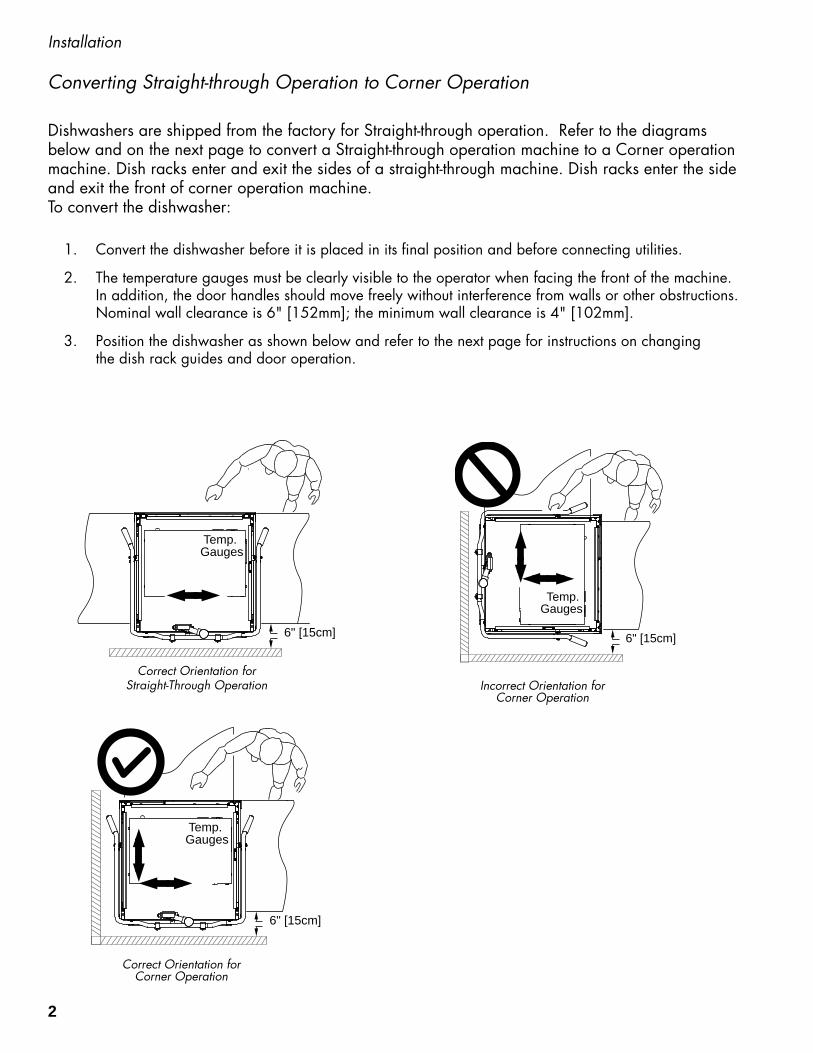
Dishwashers are shipped from the factory for Straight-through operation. Refer to the diagrams below and on the next page to convert a Straight-through operation machine to a Corner operation machine. Dish racks enter and exit the sides of a straight-through machine. Dish racks enter the side and exit the front of corner operation machine. To convert the dishwasher:
1. Convert the dishwasher before it is placed in its final position and before connecting utilities.
2. The temperature gauges must be clearly visible to the operator when facing the front of the machine. In addition, the door handles should move freely without interference from walls or other obstructions. Nominal wall clearance is 6" [152mm]; the minimum wall clearance is 4" [102mm].
3. Position the dishwasher as shown below and refer to the next page for instructions on changing the dish rack guides and door operation.
6" [15cm]
Temp. Gauges
Correct Orientation for Corner Operation
6" [15cm]
Temp. Gauges
Incorrect Orientation for Corner Operation
6" [15cm]
Temp. Gauges
Correct Orientation for Straight-Through Operation
2

Installation
Converting Straight-through Operation to Corner Operation
wallwall
A
A
To convert track guides and door-lift for corner operation:1. Remove the rack guide (A); save the fasteners.
Move (A) and re-attach as shown in the illustration at right.
2. Slide a dish rack through the machine to check the guide to dish rack clearance. The dish rack should move smoothly without binding or tipping on the guides.
3. Disconnect the door-lift bracket (B) connecting the front door and the wall-side door and discard. To seal the holes, Re-install the bolts and lockwashers that held the bracket.
4. Disconnect the door linkage arm (C) from the wall-side door and discard. Re-install the white roller (D) and hardware.
5. Disconnect the door linkage arm (C) from the other door but do not discard.
6. Lift the door handle up and back until the springs relax.
7. Adjust the door spring hooks (E) located at the rear of dishwasher to reduce door spring tension until the front and side doors open and close without binding.
B
Remove the door-lift bracket connecting the front and wall-side doors.
E
Re-adjust the door springs at the rear of the dishwasher then check that the doors open and close without binding.
Remove the door-linkage arm from the wall-side door and discard.
Re-install the white roller with existing hardware.
C D
3

Installation
Electrical Connections
ATTENTION A qualified electrician must connect the main incoming power to the dishwasher in accordance with all local codes and regulations or in the absence of local codes in accordance with the National Electrical Code.
THREE PHASEPOWER CONNECTION
208-240V/60/3
LINE IN
L1 L2 L3GRD
Standard Dishwashers are shipped from the factory for 3-phase operation.To connect the dishwasher for 3-phase operation:
1. Remove the top-mounted control cabinet cover and locate the main terminal block in the left-rear corner of the cabinet.
2. Refer to the Machine Electrical Connection Data Plate located near the main terminal block and make sure that the incoming power supply matches the machine's electrical requirements.
3. Connect the incoming 3-phase power as shown in the illustration to the right.
4. Re-install the control cabinet cover.
WARNING: Electrocution or serious injury may result when working on an energized circuit. Disconnect power at the main breaker or service disconnect switch before working on the circuit. Lock-out and tag the breaker to indicate that work is being performed on the circuit.
Three Phase Connections
Main Terminal Block
Main Terminal Block Location
NOTE: Refer to the next page for 3-phase to 1-phase field conversion instructions.
4

A standard 3-phase operation dishwasher can be converted for 1-phase operation with the installation of a jumper wire on the main terminal and rewiring of the wash tank and booster tank heaters. A jumper wire, jumper bars and a new data plate are stowed on top of the wash tank heater junction box.To convert the dishwasher from 3-phase to 1-phase operation: Install Main Terminal Block Jumper Wire
1. Disconnect all power to the machine.2. Remove the top-mounted control cabinet cover and locate the main terminal block located in the left-rear corner of the cabinet.3. Connect the jumper wire (shipped inside the control cabinet) between L2 and L3 on the output side of the main terminal block.4. Connect the 1-phase incoming power supply to L1 and L2 on the input side of the main terminal block. Rewire Wash Tank Heater Element for 1PH1. Remove the lower front panel.2. Remove the wash tank heater junction box cover.3. Remove the paper insulator and jumper bars from the heater terminals.4. Additional short jumper bars are stowed with the new data plate.5. Reposition the jumper bars for 1PH as shown below.6. Connect the #33 wire to one element terminal as shown. 7. Connect the #34 and #35 wires to the other terminals as shown.8. Reinstall the paper insulator and the junction box cover. Rewire Booster Heater Element for 1PH 1. Remove the booster heater element cover.2. Remove the paper insulator and jumper bars from the heater terminals.3. Install the jumper bars for 1PH as shown below.4. Additional short jumper bars are stowed with the new data plate.5. Connect the #36 wire to one element terminal as shown. 6. Connect the #37 and #38 wires to the other terminals as shown. 7. Reinstall the paper insulator and the booster heater element cover.
Installation
Electrical Connections
Connect the jumper wire between L2 and L3 on the output side of the main terminal block
SINGLE PHASEPOWER CONNECTION
208-240V/60/1
LINE IN
GRDL1 L2
L1 L2 L3
JUMPER
3-Phase to 1-Phase Conversion
3PH
33
34
35L3
L2
L1
3637
383PH L3
L2 L1
NOTE: The additional jumper bars needed for 1PH operation are stowed with the new data plate on top of the wash tank heater junction box.
33
3435
1PH L3
L2
L1
3637
38
1PH
L3L2
L1
ATTENTION: Affix the new data plate on top of the existing machine data plate to complete the conversion.
5

Installation
Hot Water Connection
The hot water connection is located at the lower left-rear side of the dishwasher. A 3/4" line strainer and pressure regulating valve (PRV) were installed at the factory.
1. The pressure regulating valve is stored in the dish rack, located inside the machine. remove the brass plug and install presure gauge. See the middle figure.
2. The size of the incoming hot water line should be 3/4" or larger.
3. A water hardness of 3 grains/U.S. gal [51.3 mg/L] or less is recommended.
4. The PRV should be adjusted to supply a minimum flowing pressure of 20 PSI/138 kPA during the final rinse. The maximum flowing pressure must not exceed 25 PSI/172 kPa during the final rinse.
5. The temperature of the incoming hot water must maintain a minimum temperature of 140°F/60°C for a 40°F/22°C rise booster or a minimum temperature of 110°F/43°C for a 70°F/39°C rise booster.
6. A manually operated 3/4" or larger shut-off valve should be installed in the incoming line as close to the dishwasher as possible for servicing.
Drain Connection
The incoming hot water line is a 3/4" NPT connection.
The drain water connection is a 2" slip-fit hose connection and is located at the center-rear of the machine base. It is a gravity drain.
1. The dishwasher drain is 2" O.D. hose connection.
2. A optional drain water tempering kit is available (consult the factory).
3. Drain water flow is controlled by an automatic electrically operated drain valve.
4. The floor sink and/or drain plumbing must be able to accommodate a maximum drain flow rate of 20 US gpm / 17 Imp gpm / 76 Lpm.
The drain is a 2" slip-fit hose connection.
Remove pipe plug and install pressure gauge.
REMOVE PIPE PLUG
UNSTALL GAUGE STOREDIN DISH RACK
6
Installation
NOTE:Consult a qualified chemical supplier for chemical
supplies and chemical dispensing equipment.
A commercial grade non-chlorinated detergent is recommended for use with this machine.
Chemical Dispenser Provisions
Detergent
Rinse-aid
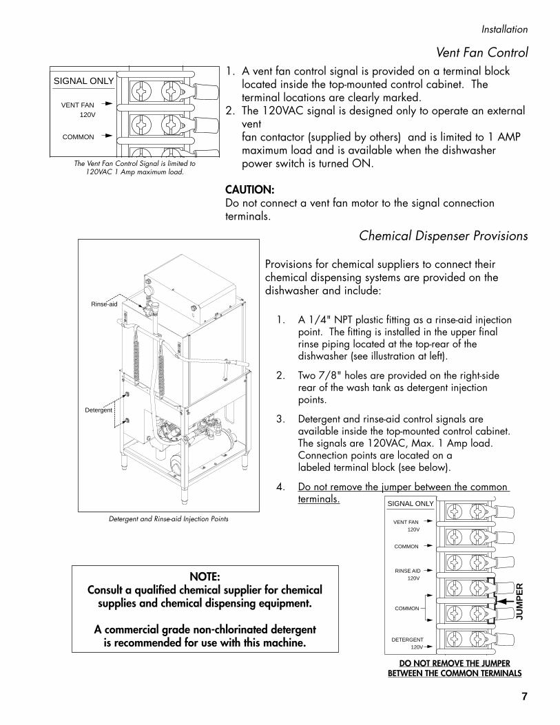
Vent Fan Control 1. A vent fan control signal is provided on a terminal block
located inside the top-mounted control cabinet. The terminal locations are clearly marked.
2. The 120VAC signal is designed only to operate an external vent fan contactor (supplied by others) and is limited to 1 AMP maximum load and is available when the dishwasher power switch is turned ON.
CAUTION:Do not connect a vent fan motor to the signal connection terminals.
SIGNAL ONLY
VENT FAN
COMMON
COMMON
120V
DETERGENT120V
RINSE AID120V
The Vent Fan Control Signal is limited to 120VAC 1 Amp maximum load.
Provisions for chemical suppliers to connect their chemical dispensing systems are provided on the dishwasher and include:
1. A 1/4" NPT plastic fitting as a rinse-aid injection point. The fitting is installed in the upper final rinse piping located at the top-rear of the dishwasher (see illustration at left).
2. Two 7/8" holes are provided on the right-side rear of the wash tank as detergent injection points.
3. Detergent and rinse-aid control signals are available inside the top-mounted control cabinet. The signals are 120VAC, Max. 1 Amp load. Connection points are located on a labeled terminal block (see below).
4. Do not remove the jumper between the common terminals.
Detergent and Rinse-aid Injection Points
SIGNAL ONLY
VENT FAN
COMMON
COMMON
120V
DETERGENT120V
RINSE AID120V
JUM
PER
DO NOT REMOVE THE JUMPER BETWEEN THE COMMON TERMINALS
7
Initial Start-up
Installation Check List
1. Remove any protective film from dishwasher. Check the interior for foreign material.
2. Make sure that the dishwasher is permanently located.
3. Make sure that all utility connections are complete.
4. Make sure that the chemical supply containers are full.
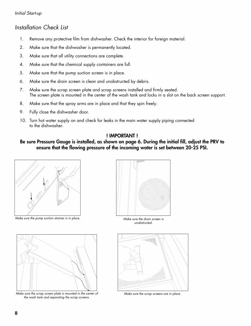
5. Make sure that the pump suction screen is in place.
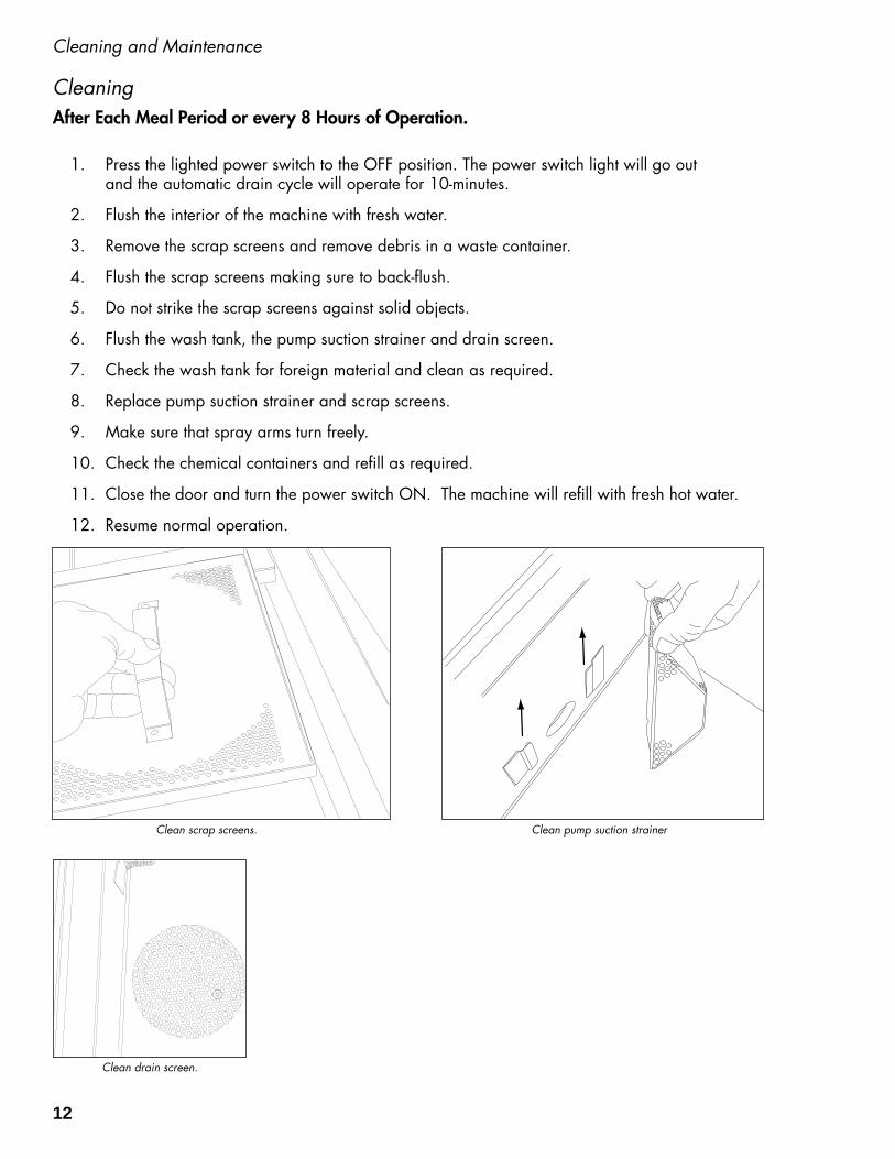
6. Make sure the drain screen is clean and unobstructed by debris.
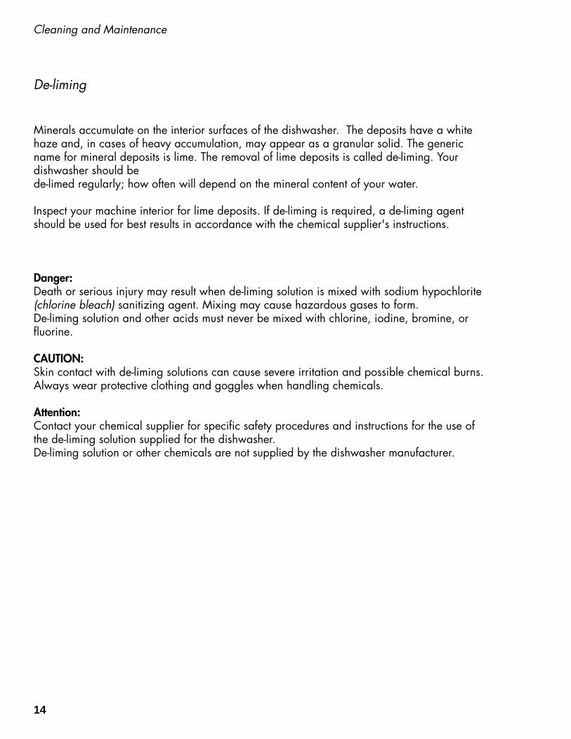
7. Make sure the scrap screen plate and scrap screens installed and firmly seated. The screen plate is mounted in the center of the wash tank and locks in a slot on the back screen support.
8. Make sure that the spray arms are in place and that they spin freely.
9. Fully close the dishwasher door.
10. Turn hot water supply on and check for leaks in the main water supply piping connected to the dishwasher.
Make sure the pump suction strainer is in place.
Make sure the scrap screen plate is mounted in the center of the wash tank and separating the scrap screens.
Make sure the scrap screens are in place.
Make sure the drain screen is unobstructed.
! IMPORTANT ! Be sure Pressure Gauge is installed, as shown on page 6. During the initial fill, adjust the PRV to
ensure that the flowing pressure of the incoming water is set between 20-25 PSI.
8

Operation
Normal Operation Mode
Door Safety Switch
Power Switch
Wash Temperature
Gauge
Final Rinse Temperature
Gauge
Pressure Gauge
In-cycle Light
Follow the instructions below to operate the dishwasher in a Normal Wash Mode. A Rinse Sentry feature holds the dishwasher in a wash mode if the booster heater temperature is below 180ºF/82ºC.
1. Turn the main power on at the main circuit breaker.
2. Make sure the spray arms and the scrap screens are in place.
3. Turn the water supply on.
4. Close the dishwasher front door.
5. Push the dishwasher Power Switch to the ON position. The power switch will illuminate and the machine will fill with water.
6. Check the pressure gauge as the machine fills and make sure the incoming water pressure is between 20-25 psi.
7. Wait up to 10-minutes for the WASH temperature gauge to indicate a minimum of 150ºF/66ºC.
8. Load soiled wares into the dish rack. Place plates, glasses, cups and bowls in a peg rack. Place utensils in a single layer in a flat-bottom rack. Place pots and pans in a flat-bottom rack. Do not overload the dish racks.
9. Slide 1 dish rack into the wash compartment making sure that wares do not interfere with the rotating spray arms. Do not wash more than 1 dish rack at a time.
10. Close the front door fully, the wash cycle will begin automatically. The green in-cycle light will illuminate.
9

Operation
Normal Operation Mode (continued)
Final RinsePressure
Wash Temperature
Final RinseTemperature
WINSTON-SALEM,NCCHAMPION INDUSTRIES, INC.
10
0
3020
PSI
60
50
40
0
20
40 60
80
100
120 140
160180
200
220
100
8060
40
20
0
20
40 60
80
100
120 140
160180
200
220
100
8060
40
20
20-25 PSI 150°F/66°C 180-195°F82-91°C
11. The wash cycle time runs for approximately 40-seconds. (continued on next page)
12. Opening the door when the dishwasher is in-cycle will stop the dishwasher. The cycle will resume automatically when the dishwasher door is closed.
13. The final rinse cycle begins at the end of the wash cycle and runs for approximately 12-seconds.
14. Check the FINAL RINSE temperature gauge during the final rinse and make sure that it indicates a minimum of 180ºF/82ºC. The acceptable range of operation is 180-195ºF/82-91ºC.
15. Check the pressure gauge located at the top of the dishwasher to ensure that the final rinse pressure maintains a flowing pressure between 20-25 PSI.
16. At the end of the rinse cycle, the in-cycle light will go out. Open the door and remove the clean rack of wares. Repeat steps 8-15 for additional dish racks.
17. Refer to the Automatic Drain Cycle on the next page for the procedures to drain the dishwasher.
The pressure gauge is located at the top of the dishwasher. The wash temperature gauge and the final rinse temperature gauges are located on the front of the control cabinet.
10

Operation
Rinse Sentry Operation Mode
The final rinse water temperature must be a minimum of 180ºF/82ºC during the final rinse cycle to ensure that all wares are sanitized. If for any reason, the hot water temperature in the booster tank cannot provide this temperature, the dishwasher will enter a Rinse Sentry Mode of operation and extend the cycle time.
The Rinse Sentry changes the Normal Operation Mode as described below:
1. The Rinse Sentry constantly monitors the water temperature inside final rinse booster.
2. If the temperature inside the booster heater falls below 180ºF/82ºC then the Rinse Sentry will extend the wash cycle time until the booster heater water temperature reaches the proper temperature.
3. The in-cycle light will remain illuminated during the Rinse Sentry Mode.
4. The RINSE water temperature gauge must be monitored to ensure that a minimum of 180ºF/82ºC is maintained during the rinse cycle.
5. The temperature range for the final rinse water is 180-195ºF/82-91ºC.
6. An extraordinarily long wash cycle may indicate a low incoming water temperature or a problem with the booster heater operation. DO NOT REMOVE WARES UNTIL THE FINAL RINSE CYCLE HAS SANITIZED THE WARES AND THE GREEN CYCLE LIGHT GOES OUT.
Automatic Drain CycleThe dishwasher can be drained automatically when the dishwasher has completed a normal wash cycle or whenever the dishwasher is idle.
To drain the dishwasher:
1. Turn the dishwasher Power Switch OFF. The automatic drain valve will open and the machine will drain.
2. The drain valve will remain open for 10-minutes to allow time to flush the interior with fresh water during a cleaning operation.
3. When 10-minutes has elapsed the drain, the drain valve will close. The automatic drain cycle is complete.
NOTE: The automatic drain cycle can be repeated after 10-minutes by turning the power Switch ON and immediately OFF. The dishwasher will drain for another 10-minutes and then turn off.
11
After Each Meal Period or every 8 Hours of Operation.
1. Press the lighted power switch to the OFF position. The power switch light will go out and the automatic drain cycle will operate for 10-minutes.
2. Flush the interior of the machine with fresh water.
3. Remove the scrap screens and remove debris in a waste container.
4. Flush the scrap screens making sure to back-flush.
5. Do not strike the scrap screens against solid objects.
6. Flush the wash tank, the pump suction strainer and drain screen.
7. Check the wash tank for foreign material and clean as required.
8. Replace pump suction strainer and scrap screens.
9. Make sure that spray arms turn freely.
10. Check the chemical containers and refill as required.
11. Close the door and turn the power switch ON. The machine will refill with fresh hot water.
12. Resume normal operation.
Cleaning and Maintenance
Cleaning
Clean scrap screens. Clean pump suction strainer
Clean drain screen.
12

Cleaning and Maintenance
At the End of the Day
1. Perform Steps 1-10 on the previous page.
2. Remove the upper and lower rinse and wash spray arms. The spray arms are interchangeable.
3. Unscrew the upper and lower rinse arm spindles (A). Remove the rinse arm assemblies
4. Clean the final rinse arm nozzles using a small paper clip (B).
5. Remove the rinse arm end plugs (C) if necessary, and flush the rinse arm with clean water.
6. Re-install the rinse arm end plugs if they were removed.
7. Remove the wash spray arms and flush with clean water.
8. DO NOT USE STEEL WOOL TO CLEAN THE INTERIOR OF THE MACHINE.
9. Contact the chemical supplier for de-liming if required (see next page).
10. Wipe the interior and exterior of the machine with a soft cloth and a mild detergent. DO NOT HOSE THE EXTERIOR OF THE MACHINE WITH WATER.
11. Reassemble the dishwasher and leave the door open to allow overnight drying.
Paper Clip
EndPlug
B
C
Wash Spray arm
Rinse Arm Spindle
D
A
13
Cleaning and Maintenance
Minerals accumulate on the interior surfaces of the dishwasher. The deposits have a white haze and, in cases of heavy accumulation, may appear as a granular solid. The generic name for mineral deposits is lime. The removal of lime deposits is called de-liming. Your dishwasher should be de-limed regularly; how often will depend on the mineral content of your water.
Inspect your machine interior for lime deposits. If de-liming is required, a de-liming agent should be used for best results in accordance with the chemical supplier's instructions.
Danger:Death or serious injury may result when de-liming solution is mixed with sodium hypochlorite (chlorine bleach) sanitizing agent. Mixing may cause hazardous gases to form.De-liming solution and other acids must never be mixed with chlorine, iodine, bromine, or fluorine.
CAUTION: Skin contact with de-liming solutions can cause severe irritation and possible chemical burns. Always wear protective clothing and goggles when handling chemicals.
Attention: Contact your chemical supplier for specific safety procedures and instructions for the use of the de-liming solution supplied for the dishwasher.De-liming solution or other chemicals are not supplied by the dishwasher manufacturer.
De-liming
14

Cleaning and Maintenance
Maintenance
Daily Maintenance
1. Check all of the wash arm and rinse arm spray jets and clean as necessary.
2. Make sure the water supply is on and that the drain is not clogged.
3. Check the temperature gauges and/or displays to ensure that they are operating.
4. Make sure dish racks are in good condition.
5. Check the chemical containers and refill as required.
6. Follow the cleaning procedures given above.
Weekly Maintenance
1. Perform Steps 1-5 in the Daily Maintenance.
2. Inspect water lines for leaks.
3. Check for water leaks underneath the dishwasher.
4. Make sure the floor drain and/or piping handles the drain water discharge.
5. Make sure the dishwasher is level.
6. Clean accumulated lime deposits from the wash tank heating element.
7. Inspect the scrap screen and replace it if damaged.
8. Check the spray arms and replace or repair if damaged.
NOTE: Consult your chemical supplier for chemical dispensing system maintenance.
15

Troubleshooting
Follow the troubleshooting guide below in the event that your dishwasher does not operate as expected. Perform the basic checks below before calling an authorized service agent:
1. Make sure that the main water supply is turned on.
2. Make sure that the main power is turned on.
3. Make sure the machine is clean.
Condition Cause Solution
Dishwasher will not run.
Low or no water.
Chemicals won’t feed intodishwasher.
Door not closed.Main power OFF.Dishwasher OFF.
Main water supply off.PRV setting incorrectLine strainer clogged.Solenoid valve defective.
Chemical supply low.Pick-up tube cloggedSupply tubing damaged.Supply tubing kinked.
Close door completely.Check breaker on panel.Turn dishwasher ON.
Open supply valve.Adjust the PRV settingContact Service Agent.Contact Service Agent.
Refill chemical container.Clean/replace tube.Replace tubing.Straighten tubing.
Dishwasher stays inwash cycle.
Rinse Sentry extends wash mode to allow final rinse water booster temperature to reach 180˚F/82˚C.
Contact Service Agent.
Dishwasher will not drain. Drain screen clogged. Clean drain screen.
Contact Service Agent.
Water spraying out of pressure gauge line.
Pressure gauge not installed in waterline.
Drain screen clogged.
Drain valve defective. Clean drain screen.
Contact Service Agent. Pressure gauge stowed indish rack when shipped.
Poor wash results. Wares incorrectly loaded. in dishrack.
Clogged screens.Clogged spray arms.
Chemical injectors not feeding.
Thermostat defective.
Detergent motor defective.
Water temperature low.
Reposition wares or reduce amount of wares.
Clean screens.Clean spray arms.
Contact Chemical Supplier.
Contact Service Agent.
Contact Service Agent
Contact Service Agent
16
17
Service Replacement Parts
Service Replacement PartsIllustrations Page
Wash Pump/Motor Assembly .................................................................................................................... 18
Booster Assembly ...................................................................................................................................... 20
Control Panel Assembly ............................................................................................................................. 22
Wash and Rinse Spray Arm Assemblies ....................................................................................................... 24
Hood and Door Assembly .......................................................................................................................... 26
Track Assembly ......................................................................................................................................... 28
Wash Tank Heat, Drain, Screens, Hoses ...................................................................................................... 30
Dish racks, Line Strainer and Pressure Regulating Vavle (PRV) ......................................................................... 32
Timer Chart ............................................................................................................................................. 35
Electrical Schematics ................................................................................................................................. 36

18
Wash Pump/Motor Assembly
12
11
10
14
13
9
87
6 5 41
2
3
19
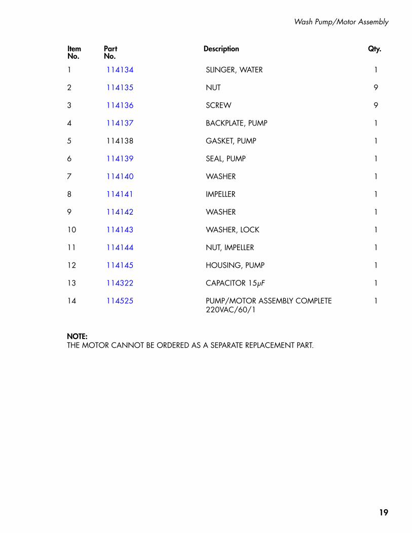
Item Part Description Qty. No. No.
1 114134 SLINGER, WATER 1
2 114135 NUT 9
3 114136 SCREW 9
4 114137 BACKPLATE, PUMP 1
5 114138 GASKET, PUMP 1
6 114139 SEAL, PUMP 1
7 114140 WASHER 1
8 114141 IMPELLER 1
9 114142 WASHER 1
10 114143 WASHER, LOCK 1
11 114144 NUT, IMPELLER 1
12 114145 HOUSING, PUMP 1
13 114322 CAPACITOR 15μF 1
14 114525 PUMP/MOTOR ASSEMBLY COMPLETE 1 220VAC/60/1
NOTE: THE MOTOR CANNOT BE ORDERED AS A SEPARATE REPLACEMENT PART.
Wash Pump/Motor Assembly
20
Booster Assembly
6
7
7
8
4
5
1
3
14
16
17
15
1312
18
1920
21
22
10
11
9
2
7
21
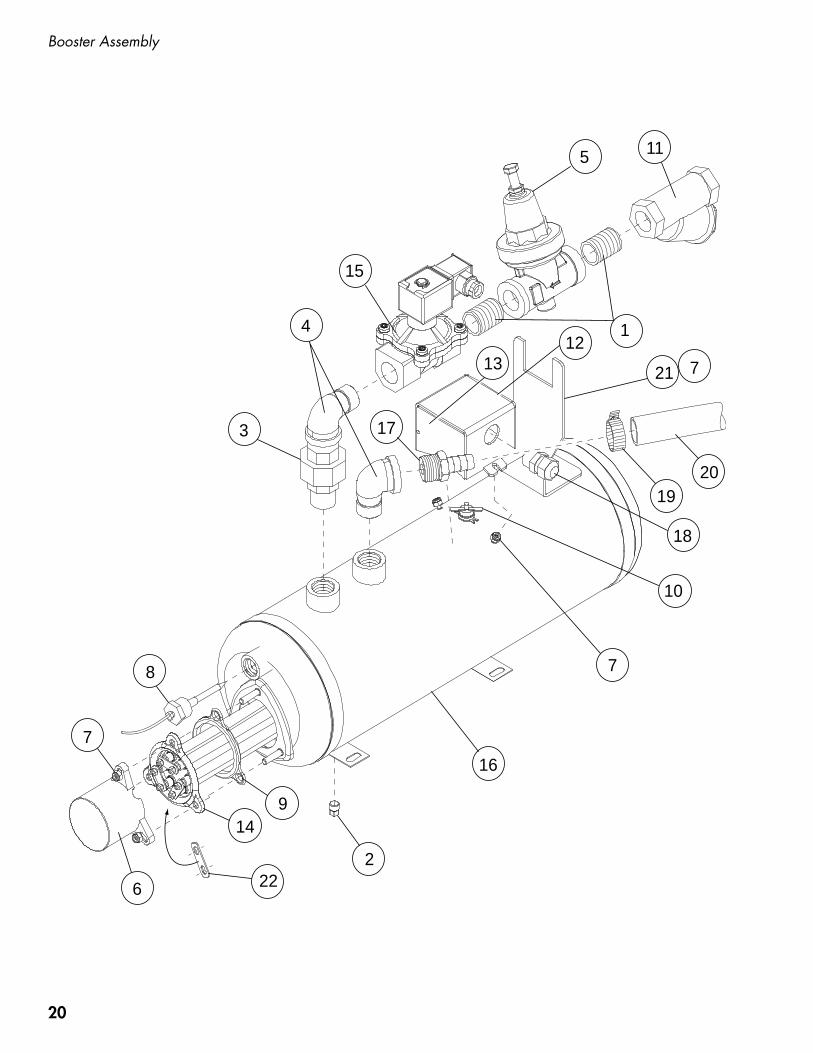
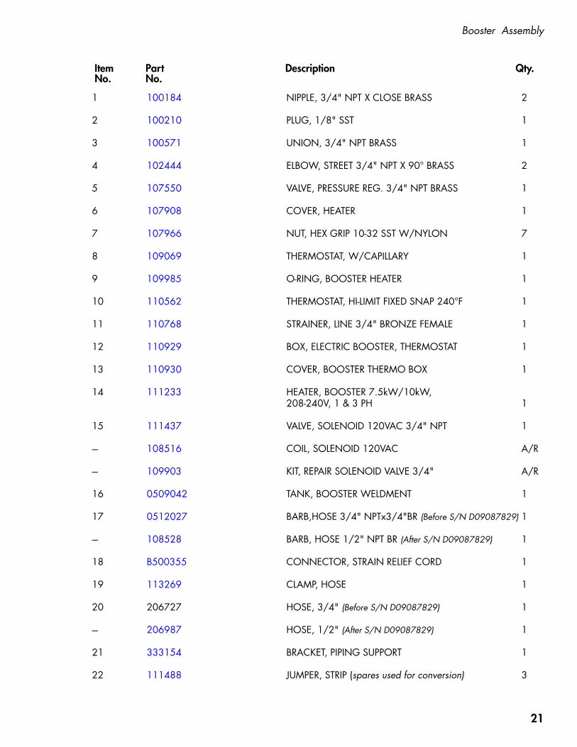
Item Part Description Qty. No. No.
1 100184 NIPPLE, 3/4" NPT X CLOSE BRASS 2
2 100210 PLUG, 1/8" SST 1
3 100571 UNION, 3/4" NPT BRASS 1
4 102444 ELBOW, STREET 3/4" NPT X 90° BRASS 2
5 107550 VALVE, PRESSURE REG. 3/4" NPT BRASS 1
6 107908 COVER, HEATER 1
7 107966 NUT, HEX GRIP 10-32 SST W/NYLON 7
8 109069 THERMOSTAT, W/CAPILLARY 1
9 109985 O-RING, BOOSTER HEATER 1
10 110562 THERMOSTAT, HI-LIMIT FIXED SNAP 240°F 1
11 110768 STRAINER, LINE 3/4" BRONZE FEMALE 1
12 110929 BOX, ELECTRIC BOOSTER, THERMOSTAT 1
13 110930 COVER, BOOSTER THERMO BOX 1
14 111233 HEATER, BOOSTER 7.5kW/10kW, 208-240V, 1 & 3 PH 1 15 111437 VALVE, SOLENOID 120VAC 3/4" NPT 1 --- 108516 COIL, SOLENOID 120VAC A/R
--- 109903 KIT, REPAIR SOLENOID VALVE 3/4" A/R
16 0509042 TANK, BOOSTER WELDMENT 1
17 0512027 BARB,HOSE 3/4" NPTx3/4"BR (Before S/N D09087829) 1
--- 108528 BARB, HOSE 1/2" NPT BR (After S/N D09087829) 1
18 B500355 CONNECTOR, STRAIN RELIEF CORD 1
19 113269 CLAMP, HOSE 1
20 206727 HOSE, 3/4" (Before S/N D09087829) 1
--- 206987 HOSE, 1/2" (After S/N D09087829) 1
21 333154 BRACKET, PIPING SUPPORT 1
22 111488 JUMPER, STRIP (spares used for conversion) 3
Booster Assembly

22
Control Panel Assembly
2
4
8
1
6
48
32
53
47
33
35
25
20
41
30
3650
51
52
49 23 24 42 39 34 40
44
45
9
10
18
11
43
46
27
28
37
22
31
21
26
5
52
2
2
54

23
Item Part Description Qty. No. No.
Control Panel Assembly
1 100003 NUT, HEX PLAIN 1/4-20 SST 82 100097 SCREW, TRUSS HD. 10-32 X 1/2" SST 73 100100 SCREW, ROUND HD. 8-32 X 1/4" SST 194 100736 BOLT, HEX HD., 1/4-20 X 3/4" SST 45 100929 FUSE, ATMR-30, 600V ONE-TIME 36 103310 LUG, GROUND 17 104873 LABEL, GROUND 18 106026 WASHER, FLAT 1/4" SST 49 106364 LIGHT, INDICATOR 110 106402 FUSE BLOCK, 2-POLE 111 106925 FUSE BLOCK, 3-POLE 112 106975 LABEL, 1CR 113 106976 LABEL, 2CR 114 106977 LABEL, 3CR 115 106980 LABEL, 1M 116 107098 LABEL, XFMR 117 107099 LABEL, 1MOL 118 107289 FUSE, 2.5 A 219 107564 SCREW, TRUSS HD. 6-32 X 1" SST 120 107964 PLUG, SNAP 121 108122 CONTACTOR, 3-POLE 122 108397 TRANSFORMER, 150VA 123 109849 INSULATION, CONTROL CABINET 124 0512220 SWITCH, ROCKER ON/OFF 125 110836 FITTING, STRAIGHT, 1/2" SEALTITE 126 110838 FITTING, STRAIGHT, 3/4" SEALTITE 127 111036 SOCKET, RELAY 2-POLE 328 111068 RELAY, 2-POLE, 10 AMP 329 111319 SCREW, TRUSS HD. 6-32 X 1/2" SST 430 111331 TERMINAL STRIP, 8-POLE 131 111628 MOTOR STARTER 132 116167 CONTACTOR, 3-POLE 40A 133 111833 TERMINAL BLOCK, INPUT 134 112086 OVERLAY, 150°F, WASH 135 112519 PLUG, SNAP 236 112614 LABEL, VENT FAN SIGNAL 137 113314 TIMER, INFITEC, 600SEC 138 113506 LABEL, MAX AMP 239 113622 GAUGE, RINSE, TEMPERATURE, 4FT. CAPILLARY 140 113644 OVERLAY, 180°F, RINSE 141 113721 SWITCH, REED ALEPH 142 114236 GAUGE, WASH, TEMPERATURE 8FT. CAPILLARY 143 114470 CONTROL BD., ELECTRONIC 144 114583 DECAL CHAMPION DH2000, CONTROL CABINET 145 114584 DECAL MOYER DIEBEL MD2000, CONTROL CABINET 146 206015 RAIL, DIN 35MM X 15MM A/R47 206016 RAIL, DIN 35MM X 15MM A/R48 331602 COVER, CONTROL CABINET, ROUND CORNERS 1 (Prior to S/N D130711000)--- 335089 COVER, CONTROL CABINET, SQUARE CORNERS 1 (From S/N D130711000 to S/N D150112221)--- 336415 COVER, CONTROL CABINET, SQUARE CORNERS 1 (From S/N D150112221 & above)49 331693 PANEL, INNER 150 115432 WASHER, SEALING 451 104925 WASHER, FENDER 452 107431 GASKET, STEAM 10FT53 116166 CONTACTOR, 3-POLE 60A (Beginning with S/N D160413495) 154 116504 BRACKET, CONTACTOR (Beginning with S/N D160413495) 1

24
Wash and Rinse Spray Arm Assemblies
37
27
28
29
33
35
34
3
16
15
24
2 3
17
14
1
4
5
8
7
6
9 8
32
19
10
12
11
23
20
18 26
18
2137
25
31
30
13
22

25
Item Part Description Qty. No. No.
1 100135 GAUGE, PRESSURE 0-60 PSI 12 100156 LOCKNUT, 3/4" NPT BRASS 13 100171 BUSHING, RED. FACE 3/4" X 1/2" BRASS 34 100599 CROSS, 3/4" NPT BRASS 15 100736 BOLT, HEX HD. 1/4-20 X 3/4" SST 26 102388 BUSHING, RED 1/2" NPT X 1/4" NPT BRASS 17 102525 TEE, RED. 3/4" X 1/2" X 3/4" NPT BRASS (Before S/N D09087829) 1--- 102514 TEE, 1/2" X 1/2" X 1/2" NPT BRASS (After S/N D09087829) 1 8 102651 NIPPLE, 3/4" NPT X 2" LG. BRASS (Before S/N D09087829) 2--- 100206 NIPPLE, 1/2" NPT, 2-1/2" LG. BRASS (After S/N D09087829) 19 104429 BREAKER, VACUUM 3/4" NPT BRASS (Before S/N D09087829) 1--- 100500 BREAKER, VACUUM 1/2" NPT BRASS (After S/N D09087829) 1--- 900837 KIT REPAIR, 3/4" VACUUM BREAKER A/R10 107463 PLUG, 1/4" NPT 111 107967 HEX GRIP NUT, 1/4-20 SST W/NYLON 212 108181 BUSHING, RED. 3/4" X 1/4" PVC 113 108620 GASKET, RINSE MANIFOLD 3/4" PIPING 114 109765 OVERLAY, PRESSURE GAUGE 115 109835 SCREW, #8 X 1/2" PHILS. SST 416 109854 GASKET, WASH STANDPIPE 117 109864 SUPPORT, WASHARM HUB 118 113514 BEARING, RINSE ARM 419 113622 THERMOMETER, 8 FT. CAPILLARY 120 0507443 SPINDLE, RINSE ARM 221 114556 NUT, RINSE ARM 222 332489 STANDPIPE, WASH WELDMENT 123 332552 SUPPORT, BRACKET 124 332553 MANIFOLD, WELDMENT RINSE STANDPIPE 125 332761 WELDMENT, WASHARM 126 332762 WELDMENT, RINSE ARM 127 100740 BOLT, HEX HD. 5/16-18 X 1" SST 428 102376 WASHER, FLAT 5/16" SST 829 106013 WASHER, LOCK SPLIT 5/16" SST 430 0507445 SPINDLE, WASH ARM 231 0507446 BEARING, WASH ARM SUPPORT 232 0512027 BARB, HOSE, ST 3/4" NPT X 3/4" H BRASS (Before S/N D09087829) 1--- 107419 BARB, HOSE, ST 1/2" NPT X 1/2" H BRASS (After S/N D09087829) 1 33 100154 NUT, HEX HD. PLAIN 5/16-18 SST 434 113269 CLAMP, HOSE 135 206727 HOSE, 3/4" 1--- 206987 HOSE, 1/2" 1 36 100171 BUSHING, FACE 3/4" X 1/2" NPT BRASS (After S/N D09087829) 237 114861 ENDCAP, HEADLESS 7/16-20 SST 4
Wash and Rinse Spray Arm Assemblies

26
Hood and Door Assembly
14
11 25 12 4 2
17
15
13
9 7
16 21 11
10 10
20 20
4
6
24
18 5
1
3 4
8
3
6 26
22 24 19
23
4
21
27
27
28
29
29
29
13

27
Item Part Description Qty. No. No.
Hood and Door Assembly
1 100002 BOLT, HEX HD., 1/4-20 X 1-3/8" SST 2
2 100738 BOLT, HEX HD., 1/4-20 X 1" SST 4
3 106014 NUT, HEX ACORN PLAIN, 1/4-20 SST 4
4 106026 WASHER, FLAT 1/4" SST 21
5 107962 HANDLE, GRIP 2
6 107967 HEX, GRIP NUT, 1/4-20 SST W/NYLON 12
7 108954 HEX, GRIP NUT, 6-32 SST W/NYLON 2
8 113745 PLUG, HOLE FDA, SILICON 4
9 113937 MAGNET, ALEPH 1
10 114154 SCREW, TRUSS HD., 1/4-20 X 1/2" SST 6
11 0310781-1 PIVOT, DOOR HANDLE 4
12 0310792-1 PLATE, DOOR PIVOT 2
13 0310843-2 WEAR STRIP, DOOR 24" LG. 6
14 332538 HOOD, WELDMENT 1
15 332546 DOOR, LH 1
16 332547 DOOR, RH 1
17 332557 DOOR, FRONT 1
18 332867 BRACKET, CONNECTION DOOR 2
19 332881 LIFT BAR, DOOR 2
20 0510459 SPRING, DOOR 2
21 0510779-1 HANDLE, DOOR 1
22 0510787-1 SPACER, LIFT BAR, DOOR 1
23 0510788-1 TUBE, SPACER 2
24 0510788-2 TUBE, SPACER 4
25 0510791-1 GASKET, DOOR PIVOT 2
26 104618 WASHER, FLAT 3/8" SST 6
27 332559 PANEL, SIDE 2
28 332540 PANEL, FRONT 1
29 104923 SCREW, 1/4-20 X 3/8" RD., HD., SST 6
28
Track Assemby
5
6
7
9
3
4
1
2
8
11
10

29
Item Part Description Qty. No. No.
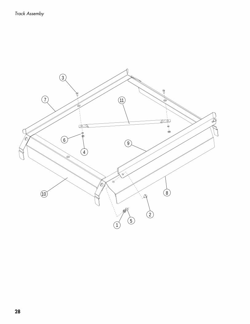
Track Assembly
1 100003 HEX PLAIN NUT, 1/4-20 SST 6
2 100073 SCREW, TRUSS HD., 1/4-20 X 1/2" SST 6
3 100754 SCREW, FLAT HD., 10-32 X 1/2" SST 2
4 104985 HEX PLAIN NUT, 10-32 SST 2
5 106482 WASHER, LOCK 1/4" SPLIT SST 6
6 106486 WASHER, LOCK #10 SPLIT, SST 2
7 332021 TRACK, REAR 1
8 332022 TRACK, FRONT 1
9 332023 TRACK, RAIL ADJUST 1
10 332024 BAFFLE, SPLASH 2
11 332025 TUBE, CROSS TRACK 1

30
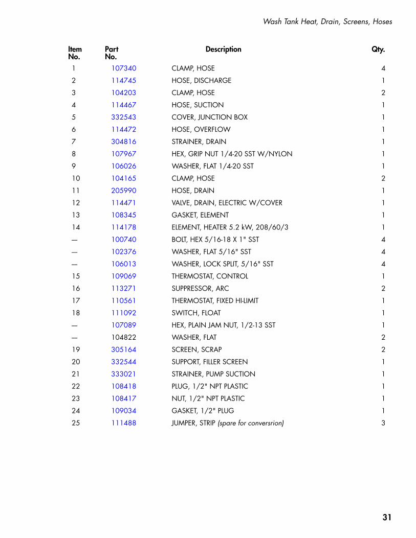
Wash Tank Heat, Drain, Screens, Hoses
3
410
10
8 59
2
1
1
3
11
12
25
13
1415
16
1617
18
19
2021
2223
24
1
1
6
7
31
Item Part Description Qty. No. No.
Wash Tank Heat, Drain, Screens, Hoses
1 107340 CLAMP, HOSE 4
2 114745 HOSE, DISCHARGE 1
3 104203 CLAMP, HOSE 2
4 114467 HOSE, SUCTION 1
5 332543 COVER, JUNCTION BOX 1
6 114472 HOSE, OVERFLOW 1
7 304816 STRAINER, DRAIN 1
8 107967 HEX, GRIP NUT 1/4-20 SST W/NYLON 1
9 106026 WASHER, FLAT 1/4-20 SST 1
10 104165 CLAMP, HOSE 2
11 205990 HOSE, DRAIN 1
12 114471 VALVE, DRAIN, ELECTRIC W/COVER 1
13 108345 GASKET, ELEMENT 1
14 114178 ELEMENT, HEATER 5.2 kW, 208/60/3 1
---- 100740 BOLT, HEX 5/16-18 X 1" SST 4
---- 102376 WASHER, FLAT 5/16" SST 4
---- 106013 WASHER, LOCK SPLIT, 5/16" SST 4
15 109069 THERMOSTAT, CONTROL 1
16 113271 SUPPRESSOR, ARC 2
17 110561 THERMOSTAT, FIXED HI-LIMIT 1
18 111092 SWITCH, FLOAT 1
---- 107089 HEX, PLAIN JAM NUT, 1/2-13 SST 1
---- 104822 WASHER, FLAT 2
19 305164 SCREEN, SCRAP 2
20 332544 SUPPORT, FILLER SCREEN 1
21 333021 STRAINER, PUMP SUCTION 1
22 108418 PLUG, 1/2" NPT PLASTIC 1
23 108417 NUT, 1/2" NPT PLASTIC 1
24 109034 GASKET, 1/2" PLUG 1
25 111488 JUMPER, STRIP (spare for conversrion) 3

32
Dish Racks, Line Strainer, PRV
1
2
3
4

33
Item Part Description Qty. No. No.
Dish Racks, Line Strainer, PRV
1 101273 DISH RACK, FLAT-BOTTOM AR 2 101285 DISH RACK, PEG AR
3 110768 STRAINER, LINE 3/4" BRONZE 1
4 107550 VALVE, PRES. REGULATING 3/4" (Optional) 1

34
Timing Chart
TIME CYCLE - DH/MD2000DWG. 114470-0/B3/10/09 L.B.
60100 20 4030 50 70 9080 100
10080 90705030 40200 10 60
60100 20 4030 50 70 9080 100
10080 90705030 40200 10 60
7 SECONDS
12 SECONDS
1 SECOND
40 SECONDSWASH0 40
60 SECONDS TOTAL CYCLE
DWELL
RINSE 41 53
53 60
SANITARY DWELL
40 41
60 seconds cycle consisting of:
40 seconds Wash 1 second Dwell 12 seconds Rinse 7 seconds Sanitary Dwell
CYCLE STRUCTURE

35
Electrical Schematic

36
Electrical Schematic

37
Kit 901078, Booster Contactor Upgrade Installation Instructions
DH
/MD
20
00
BO
OST
ER C
ON
TACTO
R
UPG
RA
DE
KIT
, P/N
90
10
78
PREP
ARA
TIO
N:
D
isco
nnec
t all
pow
er to
the
dish
was
her a
nd lo
ck o
ut ta
g ou
t the
circ
uit.
Rem
ove
blac
k bo
oste
r ele
men
t cov
er.
Not
e th
e lo
catio
n an
d di
scon
nect
the
boos
ter h
eate
r wire
s. D
isco
nnec
t the
1/2
" 90
° fle
xibl
e co
ndui
t fitti
ng fr
om th
e m
achi
ne b
ase.
Rem
ove
the
cabl
e tie
s an
d th
e ca
ble
clam
ps h
oldi
ng
the
boos
ter h
arne
ss to
the
rear
of t
he m
achi
ne.
Dis
conn
ect t
he b
ooste
r con
tact
or w
ires.
Dis
conn
ect t
he 1
/2"
strai
ght fl
exib
le c
ondu
it fit
ting
from
the
rear
of t
he c
ontro
l cab
inet
. Rem
ove
the
boos
ter h
arne
ss a
nd d
isca
rd. D
isco
nnec
t and
rem
ove
the
boos
ter a
nd w
ash
tank
hea
ter c
onta
ctor
s.
WA
RNIN
G:
Elec
troc
utio
n m
ay o
ccur
whe
n w
orki
ng o
n en
ergi
zed
circ
uits
. D
isco
nnec
t pow
er a
t the
mai
n br
eake
r or
ser
vice
dis
conn
ect s
witc
h,th
en lo
ck o
ut a
nd ta
g it
to in
dica
te th
at w
ork
is b
eing
per
form
ed o
n th
e ci
rcui
t.
PA
RT
NO
. D
ESCRIP
TIO
N
QTY
.
1161
66
Con
tact
or, 6
0A
111
6504
Br
acke
t, 60
A C
onta
ctor
Din
Rai
l Mou
ntin
g
111
4566
Ti
e, C
able
7"
411
1885
Pa
per,
Fish
2
7029
39
Har
ness
, Boo
ster w
ith 3
jum
pers
1
Kit C
onte
nts:
1
6
Rem
ove
and
rota
te th
e 40
A w
ash
cont
acto
r Din
rail
brac
ket 1
80°
as s
how
n in
No.
2.
3 Rein
stall
the
40A
con
tact
or o
n th
e D
in ra
il w
ithth
e co
il te
rmin
als
faci
ng th
e fro
nt o
f the
cab
inet
an
d th
e bl
ue a
ctua
tor f
acin
g th
e re
ar.
2
45
Insta
ll th
e D
in ra
il m
ount
ing
brac
ket o
n th
e 60
A c
onta
ctor
mak
ing
sure
the
sprin
g cl
ip is
on th
e op
posi
te e
nd o
f the
con
tact
or c
oil l
eads
as
show
n in
No.
5.
Insta
ll th
e 60
A c
onta
ctor
.
P/N
115
794
Rev.
--
7 60A
and
40A
con
tact
ors
insta
lled.
8
Insta
ll ne
w h
arne
ss m
akin
g su
reto
rout
e it
behi
nd th
e ha
ndle
.
9In
stall
the
fish
pape
r,co
nnec
t the
long
est
wire
, #38
, in
the
cent
erth
en c
onne
ct w
ires
#36
and
#37.
Rein
stall
the
blac
k co
ver.
Con
tinue
d on
nex
t pag
e
3 P
HA
SEBO
OST
ER 36
37
38

38
P/N 115794 Rev. --
#37 #38 #36
RR
RWash
Hea
terBooster
Hea
ter
PO
WER
IN36
37
38
HC
60A
MP
33
34
35
HC
40A
MP
36
37
38
33
34
18
16
L1L2
L3
L1L2
L3
35
PP
PP
PP
PP
P
Booster W
iring
Harn
ess
L1L2
30
L1L2
L1L2
L3
31
32
DH
/MD
20
00
BO
OSTER
CO
NTA
CTO
R U
PG
RA
DE K
IT, P/N
90
10
78
(continued)
Refer to
the D
iagra
m b
elow
:
1. C
onnect the #8 booster wiring harness and jum
pers as shown.
2. Reconnect the existing #10 w
ash contactor wiring previously rem
oved.3.
Tighten all terminals then tighten again to ensure they are secure.
4. Replace panels and covers.
5. Turn pow
er on and check operation.6.
Upgrade is com
plete.
Kit 901078, Booster Contactor Upgrade Installation Instructions