operating manual sru rotary lobe pumpomdean.com/.../alfa-laval_sru_rotary-lobe-pump_iom.pdf · sru...
TRANSCRIPT

Operating Manual
SRU Rotary Lobe Pump
IM70844-GB32001-08

Alfa LavalBirch Road, Eastbourne,East Sussex BN23 6PQTel No : (01323) 412555 Fax (01323) 412515
EC DECLARATION OF INCORPORATION
We hereby declare that the following machinery is intended for installation into a machineor to be assembled with other machines into a machine. It must not be put into serviceuntil the machinery into which it is incorporated has been declared in conformity with theprovisions of the Machinery Directive 89/392/EEC, amendments 91/368/EEC, 93/44/EEC, 93/68/EEC.
Machine Description
Type/Size
Serial Number
This machinery has been designed and manufactured in accordance with the followingtransposed harmonised European Standards:-
A technical construction file for this machinery is retained at the above address.
Signed Date
Name Position
Rotary Lobe Pump
EN292 Parts 1 and 2 : 1991 Safety of Machinery - Basic Concepts, general principles for design.
EN294 : 1992 Safety distances to prevent danger zones being reached by the upper limbs.
ISO9001: 1994 Quality Management System.
(Authorised Person)
P.SWEET QUALITY MANAGER

Alfa LavalBirch Road, Eastbourne,East Sussex BN23 6PQTel No : (01323) 412555 Fax (01323) 412515
EC DECLARATION OF CONFORMITY
We hereby declare that the following machinery conforms to the machinery directive 89/392/EEC as amended by 91/368/EEC, 93/44/EEC and 93/68/EEC and to thefollowing other relevant directives. The machinery has been designed and manufac-tured in accordance with the transposed harmonised European standards; Europeanand national standards as listed:
Machine Description
Type/Size Serial Number
Other Applicable Directive
Applicable Standards/Specifications
A technical construction file for this machinery is retained at the above address.
Signed Date(Authorised Person)
Name Position QUALITY MANAGER
Rotary Lobe Pump - Motorised
Electrical Equipment Low Voltage Directive 73/23/EEC
Electromagnetic Compatibility Directive 89/336/EEC
EN292 Parts 1 and 2 : 1991 Safety of Machinery - Basic concepts, general principles for design.
EN294 : 1992 Safety distances to prevent danger zones being reached by the upper limbs.
EN60204 Part 1 : 1993 Safety of Machinery - Electrical equipment of machines - specificationfor general requirements.
BS5304 : 1988 Code of Practice for Safety of Machinery.
ISO9001 : 1994 Quality Management System.
P.SWEET

1
General Description
Safety
Installation
Maintenance
Technical data
Drawings/Parts list
This manual is divided into the main sections below.
Table of contents
1. General Description ...................................... 2
1. Important Information .................................... 32. Warning Signs ............................................. 33. Safety Precautions ....................................... 4
1. Unpacking/Handling and Storage ................. 52. System Design and Installation .................... 63. Flushed Seal Arrangements ......................... 84. Pre-start Up Checks .................................... 9
1. Cleaning In Place (CIP) .............................. 102. Maintenance Schedule ............................... 103. Disassembly .............................................. 114. Assembly ................................................... 14
4.1 Fitting Bearings to Shaft ....................... 144.2 Fitting Shaft Assemblies ...................... 154.3 Fitting Seal Retainers ........................... 154.4 Checking Rotor Abutment Adjustment .. 164.5 Fitting Timing Gears ............................. 164.6 Adjusting Rotor Timing ......................... 174.7 Fitting Gearcase Cover ......................... 174.8 Fitting and Shimming Rotorcase .......... 184.9 Fitting Primary Seals............................ 184.10 Fitting Rotors ..................................... 194.11 Fitting Rotorcase Cover ...................... 19
5. Primary Seals Removal and Fitting............. 205.1 R90 Single Mechanical Seal ................. 205.2 R90 Single Flushed/Quench
Mechanical Seal ................................... 215.3 R90 Double Flushed Mechanical Seal .. 225.4 Hyclean Single Mechanical Seal .......... 235.5 Hyclean Single Flushed/Quench Mechanical Seal .................................. 245.6 Packed Gland ...................................... 25
6. Pressure Relief Valve ................................. 267. Troubleshooting .......................................... 28
1. Technical Data ........................................... 29
1. Drawing/Parts List ........ 30, 32, 34, 36, 38, 402. Exploded Drawing ........ 31, 33, 35, 37, 39, 41

2
General Description
1. General Description
The SRU pump supplied is a positive displace-ment rotary lobe pump; it may be supplied with orwithout a drive unit (see drawing). The drawingshown indicates various parts of the pump unit.
The SRU range has a universal gearbox design inseries SRU1 - 4. This enables the flexibility ofmounting pumps with the inlet and outlet ports ineither a vertical or horizontal plane. The portorientation, vertical or horizontal, may be changedby moving one of two available bolt-on feet on thegearbox. Port orientation should be specifiedwhen ordering, but the alternative foot designallows pumps that are already installed beingchanged should the need arise.
Series SRU5 & 6 pumps can also have the inletand outlet ports in either horizontal or verticalplane. This is achieved by the use of dedicatedgearbox castings having either horizontal orvertical shaft arrangements.
Noise levelsUnder certain operating conditions pumps and/ordrives and/or the systems within which they areinstalled can produce sound pressure levels inexcess of 85dB[A]. When necessary, protectionagainst noise should be taken.
Baseplate fixing holes
Couplingguard(enclosescoupling)
Rotorcase
Rotorcase cover
Ports
Product seal areaGearbox
Drive unit
Pump duty conditionsThe pump should only be used for the duty forwhich it has been specified. The operatingpressure, speed and temperature limits havebeen selected at the time of order and MUSTNOT be exceeded. These details are stated onthe original order documentation and if notavailable may be obtained from your supplierquoting pump model and serial number.

3
:
:
:
Safety
Unsafe practices and other important information areemphasized in this manual.
Warnings are emphasized by means of specialsigns.
1. Important information
Indicates that special procedures must befollowed to avoid severe personal injury.
Indicates that special procedures must befollowed to avoid damage to the pump.
Indicates important information to simplifypractices or to make them clearer.
WARNING! :
CAUTION! :
NOTE! :
2. Warning signsGeneral warning.
Dangerous electrical voltage.
Caustic agents.
Always read the manual before using the pump!

4
3. Safety precautions
Installation:
:
:
:
:
Operation:
:
:
:
:
:
:
Maintenance:
:
:
:
:
:
Always observe the technical data (see page 29).
The pump must be electrically connected byauthorised personnel (see the motorinstructions supplied with the drive unit).
Never start in the wrong direction of rotation withliquid in the pump.
Never put your hands or fingers inside the portconnections or anywhere close to rotating shafts.
Always observe the technical data (see page 29).
Never touch the pump or the pipelines whenpumping hot liquids or when sterilising.
Never stand on the pump or pipelines
Never run the pump with both the suction sideand the pressure side blocked.
Never put your hands or fingers inside the portconnections or anywhere close to rotating shafts.
Only handle toxic and acidic liquids in accord-ance with their manufacturers instructions andrecommendations.
Always observe the technical data (see page 29).
Always disconnect the power supply whenthe pump is being serviced.
The pump must never be serviced when hot.
The pump and the pipelines must never bepressurised when the pump is being serviced.
Never put your hand or fingers inside the portconnections or anywhere close to rotating shafts.
All warnings in the manual are summarised on thispage.
Pay special attention to the instructions below so thatsevere personal injury or damage to the pump areavoided.
Safety

5
1. Unpacking, Handling and Storage
1
2 3
Installation
Refer to the pump weights guide page 29 beforeselecting and using any lifting gear. The drawingsshown detail how the pump should be lifted.
Ensure that lifting equipment is correctly ratedand used within these limits.
On receipt always:- Check the delivery note against the goods
received.- If motorised, check that the drive instructions
are available.- Inspect the packing for signs of damage in
transit.- Carefully remove the packing away from the
pump.- Inspect the pump for any visible signs of
damage.- Clean away the packing from the pump port
connections.- Report any damage immediately to the
carrier.
After receipt and inspection, if the pump is not tobe installed immediately, the pump should berepacked and placed in suitable storage. Thefollowing points should be noted:
1. Plastic or gasket type port covers should beleft in place.
2. Pumps received wrapped with corrosioninhibiting treatment material should havewrapping replaced.
3. A clean, dry storage location free fromvibration should be selected. If a moist ordusty atmosphere is used for storage, furtherprotect the pump or unit with a suitablecover.
4. Rotate the pump/pump unit by hand weekly,to prevent bearing damage.
5. All associated ancillary equipment should betreated similarly.
Bareshaft pump
Pump with drive unit

6
All pipework must be supported. The pump must notbe allowed to support any of the pipework weightbeyond the limits set in the following table.
1
Installation
2. System Design and Installation
When designing the pumping system:
- Confirm the Net Positive Suction Head requirements of the pump (NPSHr) are met bythe system, as this is crucial for ensuring thesmooth operation of the pump and preventingcavitation.
- Avoid suction lifts and manifold/commonsuction lines for two pumps running in parallel,as this may cause vibration or cavitation.
PLAN VIEWSUCTION LINE
- Protect the pump against blockage from hardsolid objects e.g. nuts, bolts etc. Also protectthe pump from accidental operation against aclosed valve by using one of the followingmethods: - relief valves, pressure switch, andcurrent limiting device.
- Fit suction and discharge pressure monitorpoints for diagnostic purposes.
- Fit valves if two pumps are to be used onmanifold/common discharge lines.
- Make the necessary piping arrangements ifflushing is required for the seal or if media isrequired for heating/cooling jackets.
- Do not subject the pump to rapid temperaturechanges. Pump seizure can result from thermalshock.
Before the pump is installed it is advisable toconsider the following:
Always- Ensure that the mounting surface is flat to
avoid distortion of the baseplate, as this willcause pump / motor shaft misalignment andpump / motor unit damage.
Check- Pump shaft to motor shaft alignment is
within manufacturers limits once the baseplate has been secured.
Always allow at least 1 m for pump access /maintenance all around the pump.
2
3
DISCHARGE LINE
Table of Maximum Forces and Moments
Plane 'Y'
Plane 'Z'
Plane 'X'
Pump Forces Moments
Model FZ FY FX EF M Z MY MX EM
SRU1 Forces N 80 60 70 120
lbf 18 13 16 27
Moments Nm 75 90 115 165
lbft 55 66 85 122
SRU2 Forces N 125 100 110 195
lbf 28 22 25 44
Moments Nm 90 105 130 190
lbft 66 77 96 140
SRU3/4 Forces N 165 135 150 260
lbf 37 30 34 58
Moments Nm 100 115 140 205
lbft 74 85 103 151
SRU5/6 Forces N 300 250 250 460
lbf 67 56 56 103
Moments Nm 125 145 175 260
lbft 92 107 129 192

7
Installation
3
4
5
Remember:Pipework supports must also support the weight ofthe product being pumped.
Always:- Design short straight suction lines to reduce
friction losses in the pipework therebyimproving the NPSH available from the system.
- Avoid bends, tees and any restrictions close toeither suction or discharge side of pump. Uselong radius bends wherever possible.
Continued...
Suction
Discharge
The direction of flow is dictated by the direction ofrotation of the drive shaft. Reversing the directionof rotation will reverse the flow direction.
- Provide isolating valves on each side of thepump to isolate the pump when necessary.
- Keep pipework horizontal where applicable toreduce air locks. Include eccentric reducers onsuction lines.
Discharge Suction
Suction
Discharge
The pump will not be supplied pre-filled with oil therefore the table below must be used to selectrecommended oil.
Oil changing: - Oil level must be checked with thepump static.
First change - After 150 hours of operation,thereafter every 3000 hours of operation.
Oil filling - Fill with oil through the filler plug to thelevel indicated in the sight glass.
Refer to technical data on page 29 for oil quantities required.
Note: On horizontally ported pumps the sight glass must be fitted to the upper hole on the side of thegearcase
DischargeSuction
Pump Operating Temperature
-20° C to +130° C +130° C to 200° C (-4°F to +266°F) (+266°F to 392°F)
BP Energol GR - XP150 BP GRS15 Castrol Alpha SP150 Castrol Alpha SN150 Mobil Gear 629 Mobil Glycoyle 30 Shell Omala 150 Shell Tivela WA Texaco Meropa 150 Texaco Synlube SAE90 Esso Spartan EP150 Esso IL1947

8
1
3
2
3. Flushed seal arrangements
Installation
A flushed seal arrangement is fitted in order tocool or clean the seal area.
It is important that:
- The flush is correctly connected.(See below).
- A compatible flushing fluid is used andsupplied at the correct pressure and flowrate.
- The flush is turned on at the same time /prior to starting the pump, and turned off atthe same time/after stopping the pump.
Connecting the flushThe following equipment is stronglyrecommended when using a flushing system.
- Control valve and pressure gauge, to enablethe correct flushing pressure to be obtainedand monitored.
- Isolation valve and check valve, so that theflush can be turned off, and to stop anyunwanted substances flowing in the wrongdirection.
- A method of visibly indicating flushing fluidflow.
Flushing pipework
This suggested arrangement is for singlemechanical seals. If the pump is fitted withdouble mechanical seals or packed glands thepressure gauges and control valves should befitted on the outlet side of the system.
Suggested visible indication of flow
Pipework & fittings not normally supplied bypump manufacturer
Control valveCheck valve
Isolation valve
Flush inlet
Pressure gauge
Double mechanicalseal/packed glandonly
Pressure gaugeControlvalve
Flush outlet -to waste

9
Installation
4
Flushing fluidThe choice of flushing fluid is dependent upon thefluid being pumped and duty conditions i.e.pressure and temperature. Usually water is usedfor cooling or flushing water soluble products. Foradvice on selecting a suitable flushing fluid pleasecontact pump supplier.
Flushing pressure and flow rateSingle mechanical seal 0.5 bar ( 7 psi) maximum.Any further increase in pressure will result in lipseal failure.Double mechanical seal/flushed packed gland 1.0bar (14 psi) higher pressure than the dischargepressure of the pump. If the discharge pressurefluctuates set the pressure to suit maximumcondition.
The flushing flow rate must be adequate to ensurethat the temperature limitation of the seals is notexceeded. Contact your pump supplier for furtherinformation on the recommended flow.
5
- Check the pipework system has beenpurged to remove debris.
- Check all obstructions have been removedfrom pipework and pump.
- Check pump connections and pipeworkjoints are tight.
- Check lubrication levels are correct.- Check seal flushing is connected if
applicable.- Check all safety guards are in place.
4. Pre-start Up Checks

10
2. Maintenance Schedule
It is advisable to install pressure gauges on bothsides of pump so that any problems within thepump/pipework can be monitored.
Part Description
Lip Seal Drive EndO-ring Rotorcase CoverLip Seal Gland EndO-ring Rotor Sealing Shaft EndO-ring Rotor Sealing Nut EndPrimary Seals
Quantity
112222
Recommended spare partsThe table shows recommended spare parts thatshould be retained within yourmaintenance schedule.
Never touch the pump or the pipelines asthey will be extremely hot!
Do not subject the pump to rapidtemperature changes during CIPprocedures, as pump seizure can resultfrom thermal shock. A suitable by-passis recommended.
Maintenance
1. Cleaning In Place (CIP)
The pump can be manually cleaned or cleaned inplace (CIP). The following is an example of atypical CIP procedure. However specific advice foreach application should be sought from the pumpsupplier.
1. Flush through the system with cold water orbore water (6°C) (43°F).
2. Run hot caustic soda (70-80°C) (158-176° F)at 2.5% dilution through the system for 20-30minutes.
3. Final flush through with cold water again.
Typical CIP Procedure
Warnings
Always use rubber gloves and protectivegoggles when handling caustic agents.
Always rinse well with clean water afterusing a cleaning agent.
Always store/discharge cleaning agents inaccordance with current rules/directives.
Maintenance scheduleYour weekly schedule should include:- Checking the oil level in the gearcase with
the pump stationary.- Checking the seals for leakage and replacing
as necessary.- Checking the oil seals for leakage.- Check pumping pressures.
In certain operational circumstances the pumpwill pose a thermal hazard and as such shouldnot be touched during operation. After shutdownthe pump unit should be allowed time to cool.

11
3. Tap both sides of the rotorcase (9) with a softmallet.
4. Take care not to damage mechanicalseals. The rotorcase must not be allowed todrop onto the shafts (24 and 25) during theremoval process.
5. Shims (8) should not be removed unless rotorclearances require resetting.
3. Disassembly
Maintenance
1. Remove rotorcase cover nuts (13) andcover (12).
Removing Rotorcase
1. For packed gland seals loosen the glandfollowers to relieve the packing pressure onthe shaft.For flushed mechanical seal arrangements,remove the seal housing retaining nuts andease the seal housings from the rotorcase.
2. Remove rotorcase retaining nuts (4) andwashers (4A).
1
1. Insert a plastic/wooden block between thetwo rotors (17) to stop them turning.
2. Remove rotor retention nuts (22) and rotors.Pump series 6 rotors are retained by torquelocking assemblies, TLA’s (19) and can beremoved by:- Loosening each TLA screw in several
stages in a diametrically oppositesequence.
- Use bolts to screw into two of the TLAholes (fitted with washers) and extractthe TLA’s.
3
Before disassembling the pump refer tosafety precautions. See exploded viewdrawings (page numbers 31, 33, 35, 37, 39and 41)
Removing rotorcase cover
Removing Rotors2
Plastic orwooden block

12
4
5
6
Maintenance
1. Place a tray under the gearcase to collect the waste lubricating oil.
2. Remove the lower drain plug (45) at the side of the gearcase (1).
1. Remove screws (15).2. Remove seal retainers (14) and gasket (14A)
- on some pumps a liquid sealant may havebeen used in place of the gasket, in this casea lever may be required to remove retainers.
3. The lip seals (16) can be removed using ascrewdriver/lever once the seal retainers areremoved. It is essential to renew the lip sealsand it is recommended that new gaskets orsealant be used prior to re-assembly.
1. Remove screws (6).
2. Remove gearcase cover (5) after breaking thegasket seal then press out the lip seal (7). Itis essential to renew the lip seal prior toreassembly.
Draining Pump Lubrication
Removing Seal Retainers
Removing Gearcase Cover

13
7
8
Maintenance
9
1. Release clamp plate screws (40) on pumpseries 1, 2 and 3. Release the torque lockingassembly screws in several stages on pumpseries 4, 5 and 6.
2. Remove gears (36) using the tappedextraction holes provided, or remove shaftassembly as shown in 8 below.
1. Using a soft mallet gently tap the rear end ofeach shaft (24 and 25), to remove through thefront of the gearcase (1).
2. Support each shaft during removal from thegearcase.
3. Remove the shaft abutment spacer (27) from:- On series 1, 2, 3 and 4 and horizontally
ported 5 and 6 pumps, the bearing boreopposite the rotorcase mounting face withthe additional machining mark.
- On series 5 and 6 vertically ported pumps,the right hand bearing bore when viewed fromthe front of the pump.
1. Hold the shafts (24 and 25) in a vice usingsoft jaws to protect the areas where theseals will be located.
2. Remove the bearing nuts (30) with a ‘sharptap’ on a ‘C’ spanner. The nuts may be tightall the way off as they are fitted with threadlocking adhesive.
3. Mount the shaft vertically in a press with atool positively located against the bearinginner as shown and apply pressure to the topof the shaft so that the shaft moves throughthe bearings (26 and 31).
4. Remove each bearing set (inner and outer).Good engineering practice suggests that ifbearings are removed from the shafts for anyreason they should be renewed.
Clean and examine all components for wearor damage. Renew where necessary.
Removing Timing Gears
Shaft Assembly Removal
Bearing Removal

14
Maintenance
4. Assembly4.1 Fitting Bearings to Shafts
2Take care not to damage shaft surfaces, inparticular where the seals will be located.Ensure all fastenings are tightened to torquesettings as shown on page 29.
On series 1, 2 and 3 pumps, bearings do not requireheating. For series 4, 5 and 6 pumps, heat thebearing inner cones to 110°C (230°F).Do not use any form of live flame when heating,as this will damage bearings.
1
Position shaft (24 and 25) vertically in a vice usingsoft jaws and apply anti-seize compound to thebearing diameters.
Place the inner cone on the shaft ensuring a positivefit against the shaft shoulder.
3 4
6
1
Locate outer cup.
Repeat the above for double bearing assemblies.
5
7Apply Permabond Grade 145 or equivalent lockingcompound to the bearing nut thread.
8
Tighten the bearing nut (30), whilst at the same timerotating the bearings (26 and 31) and spacer (32).The bearings are correctly adjusted when the spacercan only be moved with a light tap of a mallet.
9 10
Apply oil to the bearings.
Allow bearings to cool (series 4, 5, 6 pumps only).Failure to do so will result in incorrectly set bearings.
Locate rear bearing cup.
Locate bearing spacer (32).

15
Maintenance
4.2 Fitting Shaft Assemblies
1
Replace the shaft abutment spacer (27) in:- On series 1, 2, 3 and 4 and horizontally
ported 5 and 6 pumps, the bearing boreopposite the rotorcase mounting face withthe additional machining mark.
- On series 5 and 6 vertically ported pumps,the right hand bearing bore when viewed fromthe front of the pump.
Using a soft faced mallet tap the shafts (24 and 25)into the gearcase (1).
2
Identify drive and auxiliary shaft positions accordingto gearcase cover (5) orientation.
3
If the bearings have been replaced a newabutment spacer will probably be needed. It isvital to ensure the rotor alignment is within thelimits set on page 16.
4.3 Fitting Seal Retainers
1
Clean the rear face of the seal retainers (14), fit inposition and tighten.
Check rotor alignment is correct by referring to therotor abutment alignment page 16.
When rotor alignment is correct remove sealretainers and press new lip seals (16) into sealretainers.
Place a new gasket (14A) or apply liquid sealantonto the front of the gearcase (1) and push the sealretainers into position. Make sure lip seals are notdamaged when sliding them onto the shafts.
Replace and tighten the screws (15).
3 4
5
2

16
Maintenance
4.4 Checking Rotor Abutment Alignment
Fit rotors onto shafts (24 and 25) and tighten rotorretention nuts (22).
If the alignment is incorrect, the shaft abutmentspacer (27) must be replaced/machined.
12
Incorrect setting of rotor alignment willdamage the pump.
4.5 Fitting Timing Gears
Slide timing gears (36) onto shafts (24 and 25),realigning timing marks.
Before fitting the torque locking devices (38)lubricate them with gear oil. Series 1, 2 and 3 highpressure pumps (i.e. LD and HD models) have twosets of elements.
Fit timing gear clamp plates (39) - series 1, 2 & 3only.
Timing adjustment is now required:Tighten one clamp plate/torque locking assemblyonly, allowing rotation of the shaft in the other gearfor timing adjustment. See Adjusting Rotor Timingpage 17.
1 2
3 4
Using a depth micrometer ensure axial alignment iswithin tolerance of 0.012mm (0.0005 in).
Series 4, 5 and 6 pumps have torque lockingassemblies.

17
4.6 Adjusting Rotor Timing
1
Set the rotors (17) to the positions shown with therotor dimples in the 6-12 o’clock plane (horizontallyported pumps) or 3-9 o’clock plane (verticallyported pumps).
Turn the shaft so that the rotors are in the newpositions as shown.
Using feeler gauges measure between the pointsindicated, turning the shaft as required.
If the measurement points are unequal tap the rotorwhich is on the free turning shaft until equalmeasurement through 6 points is achieved.
Tighten the torque locking assemblies or clampplate screws. Confirm timing is still correct.
Remove the rotors.
2
3 4
6
If the rotor timing requires adjustment (andassuming the pump has not just been re-built), it isimportant to establish the cause for the rotorsmistiming before proceeding.
5
Maintenance
4.7 Fitting Gearcase Cover
1 2
3
Clean the gearcase cover bore and remove allgasket material from the face. Press a new lip seal(7) into the cover (5).
Apply liquid gasket to the face of the cover where itmates with the gearcase.
Carefully slide the cover over the shaft ensuring thelip seal is centred and not cut or damaged. Tightenthe screws (6).
To allow timing adjustment ensure that one shaft isable to rotate within the torque lockingassembly/element. The other torque lockingassembly/element should be tightened to therecommended torque.
Dimples

18
Maintenance
4.8 Fitting and Shimming Rotorcase
The rotorcase may require re-shimming if newcomponents have been fitted. Back clearancesmust be checked before operating the pump.
Note: Your supplier can advise the correctclearances from the pump serial number. Shouldthey need adjustment follow steps below. Anyincorrect setting of clearances is likely to damagethe pump in operation.Shims vary in colour for different thickness, and aregrouped in equal packs at the top and bottom of therotorcase held in place by shim retainers.
Remove the shim retainers (8A) and fit one of thethinnest shims (8) to top and bottom position.Replace shim retainers and screws (8B).
Fit the rotorcase (9) to the gearcase (1), tighten therotorcase retaining nuts (4) and fit the rotors (17).
The back clearance can now be measured usingfeeler gauges. The additional shimming required tobring the clearances within tolerance can bedetermined, fit additional shims and re-check theclearances.
Remove the rotorcase to allow fitting of productseals.
2
3 4
1
4.9 Fitting Primary Seals
Refer to section 5 for seal fitting instructions.

19
Maintenance
4.10 Fitting Rotors
Fit new rotor O rings (18).Fit rotors (17) onto the shafts (24 and 25) with bothdimpled rotor master lobes in the 6 -12 o’clockposition (horizontally ported pumps) or 3-9 o’clockposition (vertically ported pumps).
Fit new O rings (20) to rotor retention nuts (22).Use a wooden/plastic block between the rotors tostop them turning whilst tightening the rotorretention nuts to the recommended torque settingsshown on page 29.
1
2
To check rotors are correctly synchronised turn thedrive shaft (24) by hand and check meshingclearances with feeler gauges against recommendedclearance figures.
3
4.11 Fitting Rotorcase Cover
1
Lightly smear new O ring (11) in grease and fit torotorcase cover (12).
Fit rotorcase cover onto rotorcase (9) and tightenrotorcase cover nuts (13).
2
For Bi-lobe rotors: Fit one rotor in the 6 - 12 o’ clockplane onto the top shaft and the remaining rotor inthe 3 - 9 o’clock plane on the bottom shaft. Rotatepump one full revolution ensuring there is no rotorcontact.
Refer to pump start up checks prior to operation.

20Mechanical seals are fragile. Take extreme carewhen handling.Clean components before fitting, checking there isno damage to sealing faces.New o-rings should be fitted during assembly.
Maintenance
5. Primary Seals Removal and Fitting5.1 R90 Single Mechanical Seal
Seal removal:1. Loosen the screws (7).2. Remove the rotorcase.3. Extract stationary seals (2) from rotorcase.4. Remove the rotary seal (3) from the shaft (and
abutment spacer if fitted).
Seal fitting:1. Mark the shaft to indicate the seal setting
length.2. Lightly lubricate o-rings (4 and 1) and fit to
rotary and stationary seals (3 and 2).3. If fitted replace abutment spacers. Fit rotary
seals to shafts until aligned with the settingmark.
4. Tighten the screws (7).5. Fit stationary seals to rotorcase.6. Wipe clean the sealing faces with solvent.7. Refit the rotorcase.
7
Item Description
1 Stationary seal ring o-ring 2 Stationary seal ring 3 Rotary seal ring 4 Rotary seal ring o-ring 5 Wave spring 6 Drive ring 7 Grub screw
Pump Setting Dimensionmm in
SRU1 33.6 1.32 SRU2 35.6 1.40 SRU3 38.1 1.50 SRU4 39.6 1.56 SRU5 47.6 1.87 SRU6 50.7 2.00
21
Maintenance
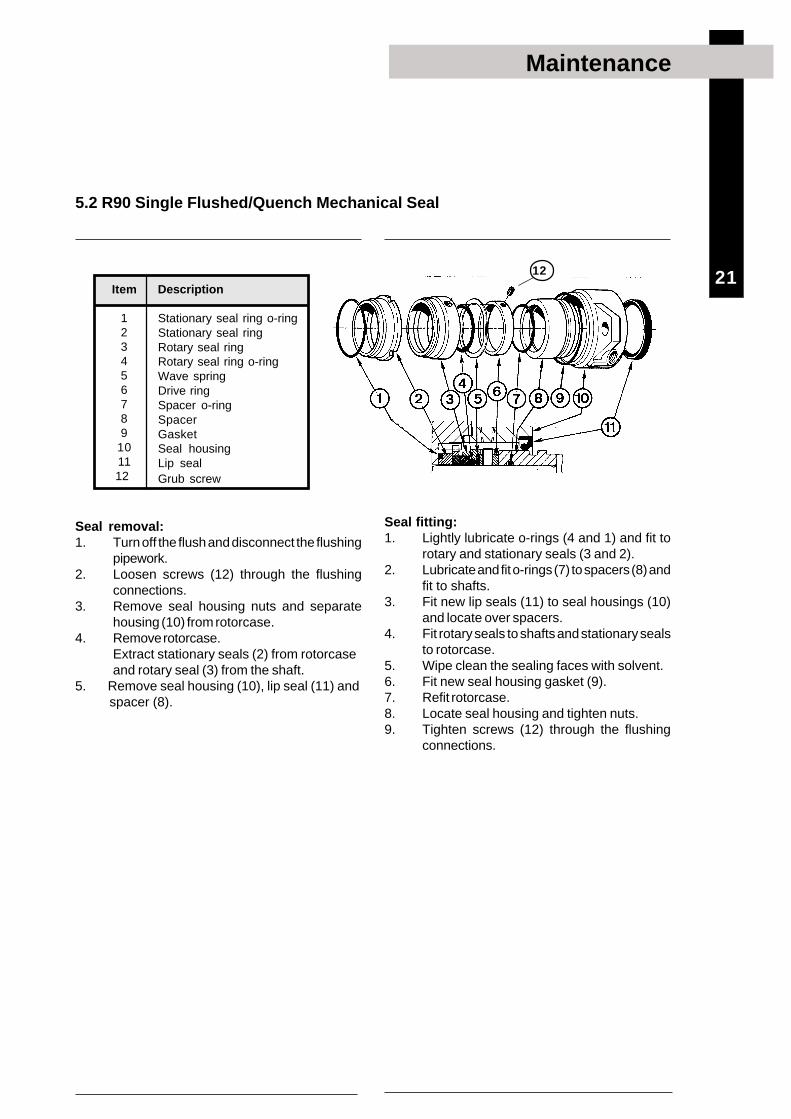
Seal removal:1. Turn off the flush and disconnect the flushing
pipework.2. Loosen screws (12) through the flushing
connections.3. Remove seal housing nuts and separate
housing (10) from rotorcase.4. Remove rotorcase.
Extract stationary seals (2) from rotorcaseand rotary seal (3) from the shaft.
5. Remove seal housing (10), lip seal (11) and spacer (8).
Item
123456789
1011
12
Description
Stationary seal ring o-ringStationary seal ringRotary seal ringRotary seal ring o-ringWave springDrive ringSpacer o-ringSpacerGasketSeal housingLip sealGrub screw
Seal fitting:1. Lightly lubricate o-rings (4 and 1) and fit to
rotary and stationary seals (3 and 2).2. Lubricate and fit o-rings (7) to spacers (8) and
fit to shafts.3. Fit new lip seals (11) to seal housings (10)
and locate over spacers.4. Fit rotary seals to shafts and stationary seals
to rotorcase.5. Wipe clean the sealing faces with solvent.6. Fit new seal housing gasket (9).7. Refit rotorcase.8. Locate seal housing and tighten nuts.9. Tighten screws (12) through the flushing
connections.
12
5.2 R90 Single Flushed/Quench Mechanical Seal

22
Maintenance
Item
123456789
10111213
14
Description
Stationary seal ring o-ringStationary seal ringRotary seal ringRotary seal ring o-ringWave springDrive ringWave springRotary seal ring o-ringRotary seal ringStationary seal ringGasketStationary seal ring o-ringSeal housingGrub screw
Seal removal:1. Turn off the flush and disconnect the flushing
pipework.2. Loosen screws (14) through the flushing
connections.3. Remove seal housing nuts and separate
housing (13) from rotorcase.4. Remove rotorcase.5. Extract stationary seals (2) from rotorcase
and rotary seal (3) from the shaft.6. Remove seal housings complete with
stationary seals.
5.3 R90 Double Flushed Mechanical Seal
Seal fitting:Ensure seal orientation is correct.1. Lightly lubricate o-rings.2. Fit o-rings (1 and 12) to stationary seals (2
and 10), and fit to seal housings (13) androtorcase.
3. Locate seal housings over shafts.4. Wipe clean the sealing faces with solvent.5. Fit O rings (4 and 8) to rotary seals (3 and 9)
and fit to shafts.6. Fit new seal housing gasket (11).7. Refit rotorcase.8. Locate seal housing and tighten nuts.9. Tighten screws (14) through the flushing
connections.
GEARCASESIDE
ROTORCASESIDE
14
Outboard
Inboard
Series 1, the outboardseal fits over theinboard seal.
Series 2-6, theinboard seal fits overthe outboard seal.
Inboard
Outboard

23
Maintenance
Seal removal:1. Remove the rotorcase.2. Remove clips (7) and stationary seals (4)
from rotorcase.3. Remove rotary seals (5) and o-rings (3) from
shafts.
Item Description
1 Rotorcase o-ring 2 Wave spring 3 Shaft o-ring 4 Stationary seal ring 5 Rotary seal ring 6 Washer 7 Clip
5.4 Hyclean Single Mechanical Seal
Seal fitting:1. Lightly lubricate the o-rings (3 and 1) and fit
to shafts and rotorcase.2. Fit washers (6) to rotary seals (5) and locate
on shafts.3. Fit wave springs (2) to stationary seals (4),
locate in rotorcase and retain with clips (7).4. Wipe clean the sealing faces with solvent.5. Refit the rotorcase.
7

24
Maintenance
Seal fitting:1. Lightly lubricate the o-rings (3 and 1) and fit
to shafts and rotorcase.2. Fit washers (6) to rotary seals (5) and locate
on shafts.3. Fit new lip seals (9) into seal housings (8).4. Fit wave springs (2) to stationary seals (4)
and locate in rotorcase.5. Fit seal housings to rotorcase with new
o-rings (7) and tighten nuts.6. Wipe clean the sealing faces with solvent.7. Refit the rotorcase.
Item Description
1 Rotorcase o-ring 2 Wave spring 3 Shaft o-ring 4 Stationary seal ring 5 Rotary seal ring 6 Washer 7 O-ring 8 Seal housing 9 Lip seal
5.5 Hyclean Single Flushed/Quench Mechanical Seal
Seal removal:1. Turn off the flush and disconnect the flushing
pipework.2. Remove the rotorcase.3. Remove seal housings (8), stationary seals
(4) and o-rings (1) from rotorcase.4. Remove rotary seals (5) and o-rings (3) from
shafts.

25
Maintenance
Packed gland fitting:Check condition of all components replacingas necessary.
1. Lubricate the o-rings (1), fit to shaft sleeves(2) and locate on shafts.
2. Tighten screws (10) and fit slingers (9).3. Fit gland spacer (3), gasket (6) and gland
housing (7) to rotorcase.4. Insert the packing rings (4), and lantern ring
(5) if fitted, as shown ensuring joints arecorrectly spaced.
5. Loosely locate the gland follower (8) andnuts.
6. Refit rotorcase with packed assemblies overshaft sleeves.
7. Adjust the packed gland.
Packed gland adjustment:Important: To prolong gland life some leakage isnecessary.8. Lightly and evenly tighten gland follower nuts.9. Start pump. Run for 10 minutes, monitoring
gland housing temperature and leakage. Glandhousing temperatures should be equal.
10. Adjust gland follower nuts by a 1/6 of a turnuntil leakage is at an acceptable rate.
Always replace gland guard after adjustment.
Item Description
1 Shaft sleeve o-ring 2 Shaft sleeve 3 Spacer 4 Packing rings 5 Lantern ring (if fitted) 6 Gasket 7 Gland housing 8 Gland follower 9 Ring slinger 10 Screw
10
5.6 Packed Gland
Packed gland removal:1. Loosen gland follower nuts.2. Remove rotorcase with gland housing (7),
packing (4) and gland follower (8) stillassembled.
3. Loosen shaft sleeve screws (10) and removesleeves (2) from shafts.

26
SRU 1-5 Relief valve
Maintenance
6. Pressure Relief ValveThe relief valve must not be disassembled whilst thepump is in operation. Always observe the safetyprecautions detailed at the front of this manual.
Take extreme care when removing the springs asthey may be compressed.
Item Description Item Description1 Rotorcase cover 14 Circlip2 Hydraulic piston 15 Bush3 ‘O’ ring, hydraulic piston 16 Valve guide4 Valve pin 17 Valve pin5 Shim 18 Spring6 Backstop disc 19 Screw7 ‘O’ ring, backstop disc 20 Valve spring guide8 Bush 21 Spring adjuster9 Screw, backstop disc 22 Washer10 Valve shaft 23 Notched nut11 ‘O’ ring, pneumatic piston 24 Valve housing12 Pneumatic piston 25 Screw13 ‘O’ ring, pneumatic piston 26 Screw, spring adjuster

27
Maintenance
3 Valve Adjustment
Thin rod
The relief valve will require setting to suit dutyrequirements.Note: A gauge is required to measure dischargepressure during adjustment1. Stop the pump2. Remove valve housing (24).3. Release notched nut(s) (23) to end of thread.4. Insert a thin rod into valve guide (16) and mark
to indicate closed position.
5. Start pump and increase pressure notingpressure gauge reading when the rod startsto move. This indicates the valve is beginningto open.
6. Tighten the notched nut gradually untildesired system pressure is achieved.(Series 6 pump only - evenly tighten thespring stack nuts after adjusting the notchednut).
7. Apply thread locking adhesive to thenotched nut after relief valve is set.
8. If pneumatic override is required connectair supply and adjust pressure until valveopens. Check piston reseats when airsupply is disconnected.
9. Replace valve housing and screws.
New o-rings should be fitted during assembly.Clean components before fitting; check there is nodamage to faces.
1. Lubricate all o-rings.2. Fit o-ring (7) to backstop disc (6) and fit
backstop disc to valve shaft (10).3. Fit o-ring (3) to hydraulic piston (2) and
screw onto valve shaft.4. Locate assembly into rotorcase cover,
replace backstop disc screws (9).5. Fit pneumatic piston o-rings (11 and 13) and
locate assembly on valve shaft. Replacecirclip (14) and springs (18).(Series 6 pumps only - each spring stackshould contain an equal amount ofsprings, noting correct orientation).Place valve guide (16) over springs andreplace screws (26).
6. Fit spring adjuster (21) and notched nut (23),valve housing (24) and screw (25).
7. Replace manual override lever if applicable.
2 Relief Valve AssemblyRelief Valve Disassembly11. Remove manual override lever if fitted.2. Remove screws (25) and valve housing (24).3. Remove notched nut(s) (23) and spring
adjuster (21). If springs are still compressedwhen the notched nut reaches end of thread,release the spring adjuster screws (26).
4. Remove springs (18) (series 1-5), springstacks (series 6), screws and valve guide(16).
5. Remove circlip (14) and pneumatic piston(12).
6. Remove screws, backstop disc (6) andhydraulic piston (2).
7. Unscrew hydraulic piston (2) from valve shaft(10) and remove o-rings (3, 7, 11 and 13).

28
Maintenance
ü ü Incorrect direction of rotation. Reverse motor.ü Pump not primed. Expel gas from suction line and pumping chamber and
introduce fluid.Increase suction line diameter.
ü ü ü ü ü ü Insufficient NPSH available. Increase suction head.Simplify suction line configuration and reduce length.Reduce pump speed.Increase suction line diameter.
ü ü ü ü ü Fluid vaporising in suction line. Increase suction head.Simplify suction line configuration and reduce length.Reduce pump speed.
ü ü ü ü ü ü Air entering suction line. Remake pipework joints. ü ü ü ü ü Strainer or filter blocked. Service fittings.
Increase fluid temperature. ü ü ü ü ü ü ü ü Fluid viscosity above rated figure. Decrease pump speed.
Check seal face viscosity limitations.ü ü ü Fluid viscosity below rated figure. Decrease fluid temperature.
Increase pump speed.Cool the pump casing.
ü ü ü ü ü Fluid temperature above rated figure. Reduce fluid temperature.Check seal face and elastomer temperature limitations.
ü ü ü Fluid temperature below rated figure. Heat the pump casing.Increase fluid temperature.Clean the system.
ü ü ü ü Unexpected solids in fluid. Fit strainer to suction line.If solids cannot be eliminated, consider fitting doublemechanical seals.
Check for obstructions i.e. closed valve.ü ü ü ü ü ü ü ü ü ü ü ü ü Discharge pressure above rated figure. Service system and change to prevent problem
recurring.Simplify discharge line to decrease pressure.
ü ü ü ü Gland over-tightened. Slacken and re-adjust gland packing. ü ü ü ü ü Gland under-tightened. Adjust gland packing. ü ü Seal flushing inadequate. Increase flush flow rate.
Check that flush fluid flows freely into seal area. ü ü ü ü Pump speed above rated figure. Decrease pump speed.ü ü Pump speed below rated figure. Increase pump speed.
Check alignment of pipes. ü ü ü ü üü ü Pump casing strained by pipework. Fit flexible pipes or expansion fittings.
Support pipework. ü ü ü ü Flexible coupling misaligned. Check alignment and adjust mountings accordingly. ü ü ü ü ü ü Insecure pump driver mountings. Fit lock washers to slack fasteners and re-tighten. ü ü ü ü ü ü ü ü Shaft bearing wear or failure. Refer to pump maker for advice and replacement parts. ü ü ü ü ü ü Insufficient gearcase lubrication. Refer to pump maker’s instructions.ü ü ü ü üü ü ü Metal to metal contact of pumping Check rated and duty pressures.
element. Refer to pump maker.ü ü ü Worn pumping element. Fit new components.
Check pressure setting and re-adjust if necessary.ü ü ü Rotorcase cover relief valve leakage. Examine and clean seating surfaces.
Replace worn parts. ü ü Rotorcase cover relief valve chatter. Check for wear on sealing surfaces, guides etc -
replace as necessary.
ü ü Rotorcase cover relief valve incorrectly Re-adjust spring compression - valve should lift approx.
set. 10% above duty pressure.ü ü Suction lift too high. Lower pump or raise liquid level. ü ü Fluid pumped not compatible with Use optional materials.
materials used ü No barrier in system to prevent flow Ensure discharge pipework higher than suction tank.
passing ü ü Pump allowed to run dry. Ensure system operation prevents this.
Fit single or double flushed mechanical seals.Fit flushed packed gland.
ü ü Faulty motor. Check and replace motor bearings.ü Pumping element missing Fit pumping element.
7. Troubleshooting
Problem
Probable Causes Solutions
No
flow
Und
er c
apac
ityIr
regu
lar d
isch
arge
Low
dis
char
ge p
ress
ure
Pum
p w
ill n
ot p
rime
Prim
e lo
st a
fter
star
ting
Pum
p st
alls
whe
n st
artin
gP
ump
over
heat
sM
otor
ove
rhea
tsE
xces
sive
pow
er a
bsor
bed
Noi
se a
nd v
ibra
tion
Pum
p el
emen
t wea
rS
ypho
ning
Sei
zure
Mec
hani
cal s
eal l
eaka
geP
acke
d gl
and
leak
age

29
1. Technical data
Oil Capacities
Technical data
Weights
Pump Bare Shaft Pump kg (lb) Pump with drive unit kg (lb)Model Horizontal Vertical Horizontal Vertical
porting porting porting porting
SRU1/005 15 (33) 16 (35) 45 (99) 46 (101)SRU1/008 17 (37) 18 (40) 55 (121) 56 (123)SRU2/013 28 (62) 30 (66) 75 (165) 77 (170)SRU2/018 29 (64) 31 (68) 80 (176) 82 (181)SRU3/027 53 (117) 56 (123) 145 (320) 148 (326)SRU3/038 56 (123) 59 (130) 150 (331) 153 (337)SRU4/055 105 (231) 111 (245) 260 (573) 266 (586)SRU4/079 110 (243) 116 (256) 265 (584) 271 (597)SRU5/116 152 (335) 152 (335) 400 (882) 400 (882)SRU5/168 160 (353) 160 (353) 415 (915) 415 (915)SRU6/260 260 (573) 260 (573) 525 (1157) 525 (1157)
SRU6/353 265 (584) 265 (584) 545 (1202) 545 (1202)The above weights are for guidance purposes only and will vary dependent uponspecification of pump, baseplate and drive unit.
Pump Model Port Orientation Port Orientation
Vertical Horizontal Vertical Horizontal
litres litres US pints US pints
SRU1 0.28 0.38 0.6 0.8
SRU2 0.55 0.65 1.2 1.4
SRU3 1.05 1.48 2.2 3.1
SRU4 1.50 2.00 3.2 4.2
SRU5 5.00 0.62 (top chamber) 10.6 1.3 (top chamber)
1.38 (bottom chamber) 2.9 (bottom chamber)
SRU6 8.50 1.30 (top chamber) 18.0 2.8 (top chamber)
2.30 (bottom chamber) 4.9 (bottom chamber)
Pump Model
Description Tool required SRU1 SRU2 SRU3 SRU4 SRU5 SRU6
Rotorcase cover nut (13) Socket Size (mm) 13 17 17 17 17 19
Torque Setting (Nm) 20 39 39 39 39 105
Torque Setting (lbft) 14.8 28.8 28.8 28.8 28.8 77.4
Rotor retention nut (22) Socket Size (mm) 17 24 24 36 36 36
Torque Setting (Nm) 14 77 120 161 161 161
Torque Setting (lbft) 10.3 56.8 88.5 118.8 118.8 118.8
Rotor TLA (19) Key Size (mm) - - - - - 5
Torque Setting (Nm) - - - - - 14
Torque Setting (lbft) - - - - - 10.3
Rotorcase retaining nut (4) Spanner Size (mm) 13 17 17 19 19 24
Torque Setting (Nm) 20 40 40 64 64 175
Torque Setting (lbft) 14.8 29.5 29.5 47.2 47.2 129.1
Seal retainer screw (15) Key Size (mm) 5 5 5 6 6 6
Torque Setting (Nm) 10 10 10 25 25 25
Torque Setting (lbft) 7.4 7.4 7.4 18.4 18.4 18.4
Gearcase cover screw (6) Key Size (mm) 5 5 5 6 6 6
Torque Setting (Nm) 10 10 10 25 25 25
Torque Setting (lbft) 7.4 7.4 7.4 18.4 18.4 18.4
TLA/Clamp plate screw (40) Key Size (mm) 5 5 5 5 6 6
Torque Setting (Nm) 12 17 12 14 35 35
Torque Setting (lbft) 8.9 12.5 8.9 10.3 25.8 25.8
Drain plug (45) Key Size (in) ¼ ¼ ¼ ¼ ½ ½
Tool Requirements
30
Drawing/Parts list
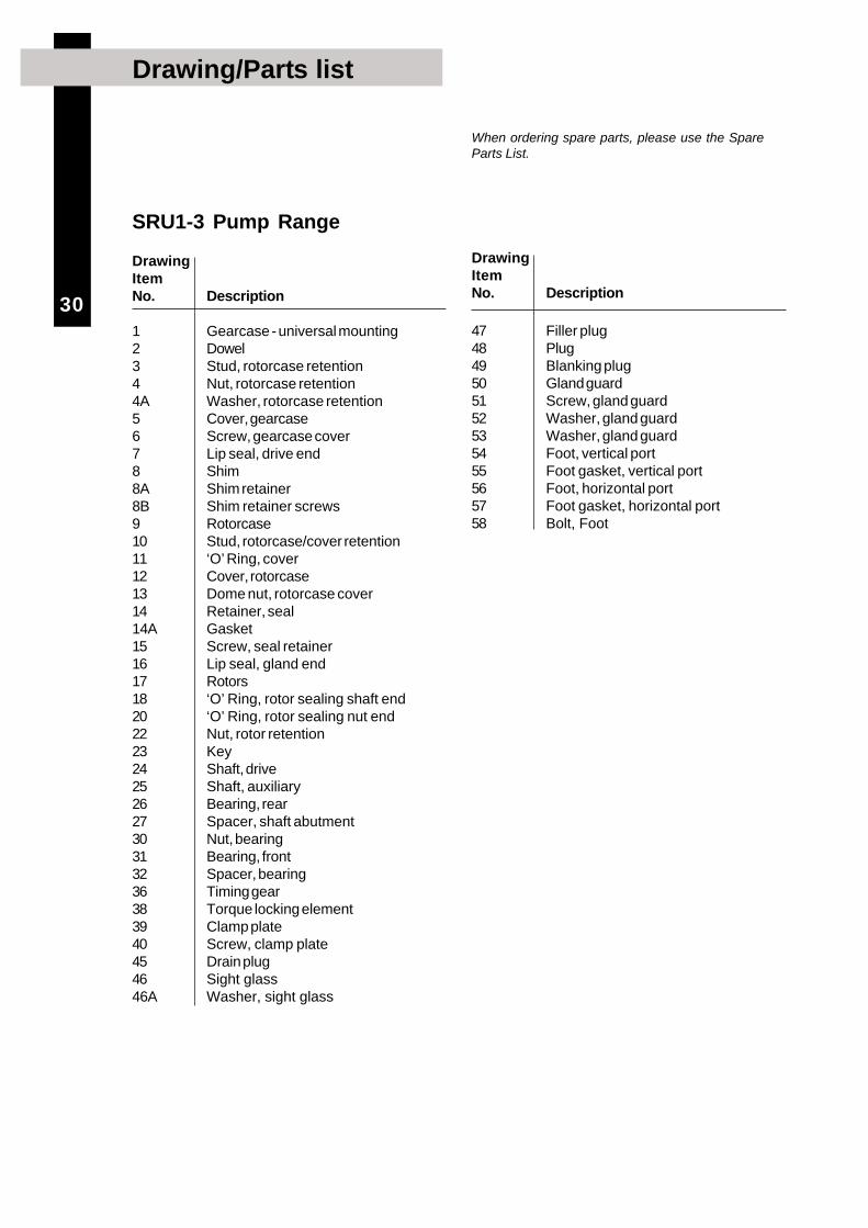
SRU1-3 Pump Range
DrawingItemNo. Description
1 Gearcase - universal mounting2 Dowel3 Stud, rotorcase retention4 Nut, rotorcase retention4A Washer, rotorcase retention5 Cover, gearcase6 Screw, gearcase cover7 Lip seal, drive end8 Shim8A Shim retainer8B Shim retainer screws9 Rotorcase10 Stud, rotorcase/cover retention11 ‘O’ Ring, cover12 Cover, rotorcase13 Dome nut, rotorcase cover14 Retainer, seal14A Gasket15 Screw, seal retainer16 Lip seal, gland end17 Rotors18 ‘O’ Ring, rotor sealing shaft end20 ‘O’ Ring, rotor sealing nut end22 Nut, rotor retention23 Key24 Shaft, drive25 Shaft, auxiliary26 Bearing, rear27 Spacer, shaft abutment30 Nut, bearing31 Bearing, front32 Spacer, bearing36 Timing gear38 Torque locking element39 Clamp plate40 Screw, clamp plate45 Drain plug46 Sight glass46A Washer, sight glass
When ordering spare parts, please use the SpareParts List.
DrawingItemNo. Description
47 Filler plug48 Plug49 Blanking plug50 Gland guard51 Screw, gland guard52 Washer, gland guard53 Washer, gland guard54 Foot, vertical port55 Foot gasket, vertical port56 Foot, horizontal port57 Foot gasket, horizontal port58 Bolt, Foot

31
Exploded drawing
The drawing shows all items of the pump and areidentical with items shown in the Spare Parts List.
SRU1-3 Pump Range

32
Drawing/Parts list
SRU4 Pump Range
DrawingItemNo. Description
1 Gearcase - universal mounting2 Dowel3 Stud, rotorcase retention4 Nut, rotorcase retention4A Washer, rotorcase retention5 Cover, gearcase6 Screw, gearcase cover7 Lip seal, drive end8 Shim8A Shim retainer8B Shim retainer screws9 Rotorcase10 Stud, rotorcase/cover retention11 ‘O’ Ring, cover12 Cover, rotorcase13 Dome nut, rotorcase cover14 Retainer, seal14A Gasket15 Screw, seal retainer15A Screw, seal retainer16 Lip seal, gland end17 Rotors18 ‘O’ Ring, rotor sealing shaft end20 ‘O’ Ring, rotor sealing nut end22 Nut, rotor retention23 Key24 Shaft, drive25 Shaft, auxiliary26 Bearing, rear27 Spacer, shaft abutment28 Spacer, bearing drive end29 Spacer, bearing gland end30 Nut, bearing rear31 Bearing, front34 Nut, bearing front36 Timing gear37 Torque locking assembly45 Drain plug46 Sight glass46A Washer, sight glass
When ordering spare parts, please use the SpareParts List.
DrawingItemNo. Description
47 Filler plug48 Plug49 Blanking plug50 Gland guard51 Screw, gland guard52 Washer, gland guard53 Washer, gland guard54 Foot, vertical port55 Foot gasket, vertical port56 Foot, horizontal port57 Foot gasket, horizontal port58 Bolt, Foot

33
Exploded drawing
The drawing shows all items of the pump and areidentical with items shown in the Spare Parts List.
SRU4 Pump Range

34
Drawing/Parts list
SRU5 Pump Range - Horizontally Ported
DrawingItemNo. Description
1 Gearcase2 Dowel3 Stud, rotorcase retention4 Nut, rotorcase retention4A Washer, rotorcase retention5 Cover, gearcase6 Screw, gearcase cover7 Lip seal, drive end8 Shim8A Shim retainer8B Shim retainer screws9 Rotorcase10 Stud, rotorcase/cover retention11 O-ring, cover12 Cover, rotorcase13 Dome nut, rotorcase cover14 Retainer, seal14A Gasket15 Screw, seal retainer16 Lip seal, gland end17 Rotors18 O-ring, rotor sealing shaft end20 O-ring, rotor sealing nut end22 Nut, rotor retention23 Key24 Shaft, drive25 Shaft, auxiliary26 Bearing, rear27 Spacer, shaft abutment28 Spacer, bearing drive end29 Spacer, bearing gland end30 Nut, bearing rear31 Bearing, front34 Nut, bearing front35 Lip seal, upper chamber36 Timing gear37 Torque locking assembly45 Drain plug46 Sight glass46A Washer, sight glass47 Filler plug
When ordering spare parts, please use the SpareParts List.
35
Exploded drawing
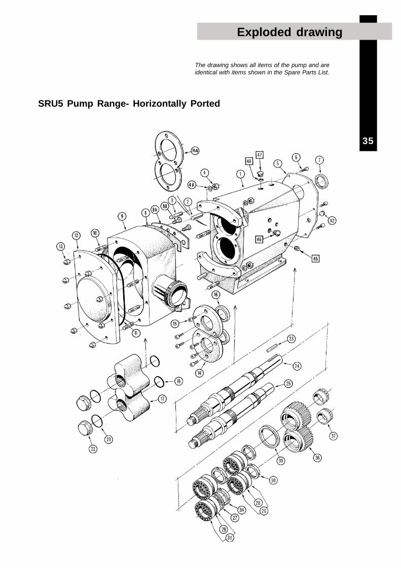
The drawing shows all items of the pump and areidentical with items shown in the Spare Parts List.
SRU5 Pump Range- Horizontally Ported
36
Drawing/Parts list
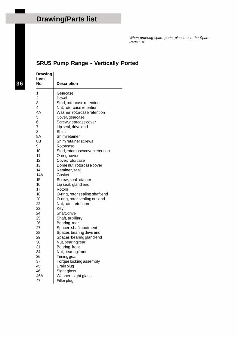
SRU5 Pump Range - Vertically Ported
DrawingItemNo. Description
1 Gearcase2 Dowel3 Stud, rotorcase retention4 Nut, rotorcase retention4A Washer, rotorcase retention5 Cover, gearcase6 Screw, gearcase cover7 Lip seal, drive end8 Shim8A Shim retainer8B Shim retainer screws9 Rotorcase10 Stud, rotorcase/cover retention11 O-ring, cover12 Cover, rotorcase13 Dome nut, rotorcase cover14 Retainer, seal14A Gasket15 Screw, seal retainer16 Lip seal, gland end17 Rotors18 O-ring, rotor sealing shaft end20 O-ring, rotor sealing nut end22 Nut, rotor retention23 Key24 Shaft, drive25 Shaft, auxiliary26 Bearing, rear27 Spacer, shaft abutment28 Spacer, bearing drive end29 Spacer, bearing gland end30 Nut, bearing rear31 Bearing, front34 Nut, bearing front36 Timing gear37 Torque locking assembly45 Drain plug46 Sight glass46A Washer, sight glass47 Filler plug
When ordering spare parts, please use the SpareParts List.

37
Exploded drawing
The drawing shows all items of the pump and areidentical with items shown in the Spare Parts List.
SRU5 Pump Range- Vertically Ported

38
Drawing/Parts list
SRU6 Pump Range - Horizontally Ported
DrawingItemNo. Description
1 Gearcase2 Dowel3 Stud, rotorcase retention4 Nut, rotorcase retention4A Washer, rotorcase retention5 Cover, gearcase6 Screw, gearcase cover7 Lip seal, drive end8 Shim8 Shim retainer8B Shim retainer screws9 Rotorcase10 Stud, rotorcase/cover retention11 O-ring, cover12 Cover, rotorcase13 Dome nut, rotorcase cover14 Retainer, seal14A Gasket15 Screw, seal retainer16 Lip seal, gland end17 Rotors18 O-ring, rotor sealing shaft end19 Torque locking assembly20 O-ring, rotor sealing nut end22 Nut, rotor retention23 Key24 Shaft, drive25 Shaft, auxiliary26 Bearing, rear27 Spacer, shaft abutment28 Spacer, bearing drive end29 Spacer, bearing gland end30 Nut, bearing rear31 Bearing, front34 Nut, bearing front35 Lip seal, upper chamber36 Timing gear37 Torque locking assembly45 Drain plug46 Sight glass46A Washer, sight glass47 Filler plug
When ordering spare parts, please use the SpareParts List.

39
Exploded drawing
The drawing shows all items of the pump and areidentical with items shown in the Spare Parts List.
SRU6 Pump Range- Horizontally Ported

40
Drawing/Parts list
SRU6 Pump Range - Vertically Ported
DrawingItemNo. Description
1 Gearcase2 Dowel3 Stud, rotorcase retention4 Nut, rotorcase retention4A Washer, rotorcase retention5 Cover, gearcase6 Screw, gearcase cover7 Lip seal, drive end8 Shim8A Shim retainer8B Shim retainer screws9 Rotorcase10 Stud, rotorcase/cover retention11 O-ring, cover12 Cover, rotorcase13 Dome nut, rotorcase cover14 Retainer, seal14A Gasket15 Screw, seal retainer16 Lip seal, gland end17 Rotors18 O-ring, rotor sealing shaft end19 Torque locking assembly20 O-ring, rotor sealing nut end22 Nut, rotor retention23 Key24 Shaft, drive25 Shaft, auxiliary26 Bearing, rear27 Spacer, shaft abutment28 Spacer, bearing drive end29 Spacer, bearing gland end30 Nut, bearing rear31 Bearing, front34 Nut, bearing front36 Timing gear37 Torque locking assembly45 Drain plug46 Sight glass46A Washer, sight glass47 Filler plug
When ordering spare parts, please use the SpareParts List.

41
Exploded drawing
The drawing shows all items of the pump and areidentical with items shown in the Spare Parts List.
SRU6 Pump Range- Vertically Ported

IM70
844-
GB
3 20
01-0
8
The information contained herein iscorrect at the time of issue but maybe subject to change without priornotice.
Sanitary Equipment, HeadquarterAlfa Laval ABP O Box 73SE-221 00 LUND, SwedenTelephone: +46 46 367000Fax: +46 46 367150Email: [email protected]
Central States Industrial2700 Partnership BoulevardSpringfield, MO 65803800.654.5635http://www.csidesigns.com