operating manual ms220ka and msr220ka · ziehl industrie – elektronik gmbh + co kg daimlerstraße...
TRANSCRIPT
ZIEHL industrie – elektronik GmbH + Co KG Daimlerstraße 13, D – 74523 Schwäbisch Hall + 49 791 504-0, [email protected], www.ziehl.de Temperature Relays and MINIKA®, Mains Monitoring, Digital Panel meters MINIPAN®, Switching Relays and Controls
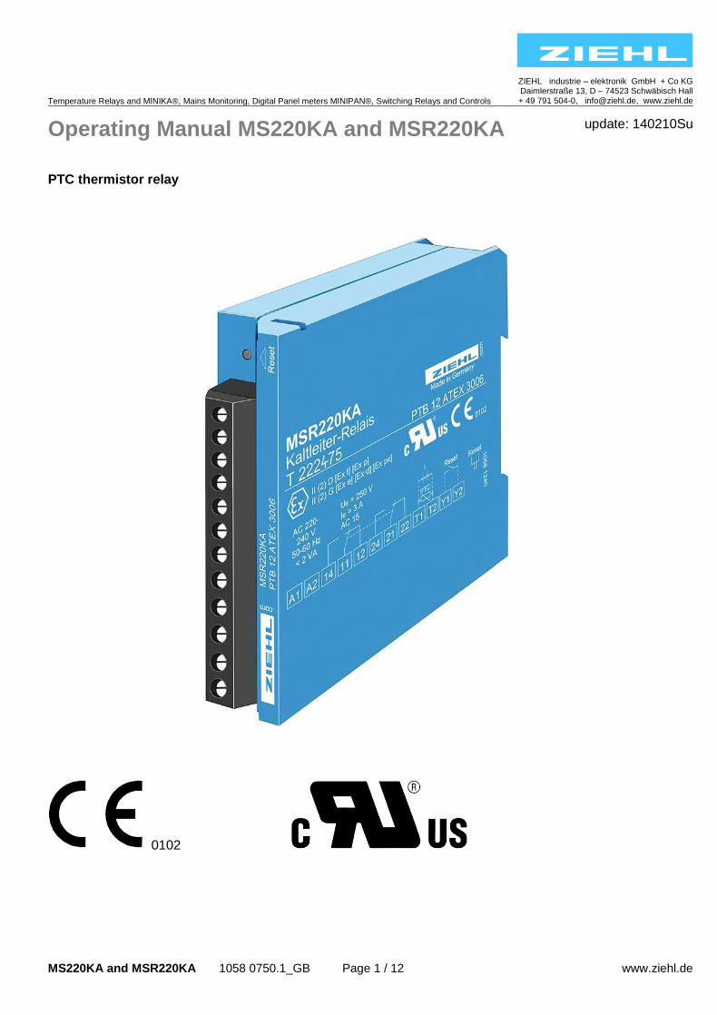
Operating Manual MS220KA and MSR220KA update: 140210Su
MS220KA and MSR220KA 1058 0750.1_GB Page 1 / 12 www.ziehl.de
PTC thermistor relay
0102
MS220KA and MSR220KA 1058 0750.1_GB Seite 2 / 12 www.ziehl.de
Table of contents 1 Application and brief description .......................................................................................................... 3
2 Approvals ................................................................................................................................................ 3
3 Features .................................................................................................................................................. 3
4 Connecting diagram ............................................................................................................................... 3
5 Display- and control elements ............................................................................................................... 4
6 Detailed description ............................................................................................................................... 4
7 Function diagram ................................................................................................................................... 5
8 Installation / commissioning .................................................................................................................. 6
9 Trouble – shooting and remedies .......................................................................................................... 6
10 Technical data ........................................................................................................................................ 7
11 Design V2 ................................................................................................................................................ 8
12 Safety Instructions and references for putting into operation ............................................................ 9
12.1 Special remarks for explosive gas atmospheres areas (Zone 0, Zone 1 and Zone 2) ...................... 9
12.2 Special remarks for use in the presence of combustible dust! (Zone 20, Zone 21 and Zone 22) ..... 9
12.3 Safety characteristics of the safety device ......................................................................................... 9
12.4 Category and Performance-Level (EN ISO 13849-1) ....................................................................... 10
12.5 Application of the safety device used with equipment category (EN 50495/VDE 0171-18) ............ 10
12.6 Wiring ................................................................................................................................................. 10
12.7 Safe Separation ................................................................................................................................. 11
12.8 Stop function ...................................................................................................................................... 11
12.9 Start and Restart ............................................................................................................................... 11
13 Proof testing of the safety functions ................................................................................................... 12
14 Maintenance and repair ........................................................................................................................ 12
MS220KA and MSR220KA 1058 0750.1_GB Seite 3 / 12 www.ziehl.de
1 Application and brief description
Ziehl PTC thermistor relays protect motors, transformers, machines and equipment against thermal overload. These are according to DIN EN 60947-8 and are thus exchangeable. Used in conjunction with respective PTC thermistors they provide a reliable temperature protection in the temperature range 60 °C up to 180 °C. PTC-thermistors according DIN 44081 and DIN 44082 shall be connected. PTC thermistors are suitable for the installation into windings of electrical machines, bearings and transformers as well as to monitor the temperature of liquid media, airflow and gases. With ATEX approval, explosion-protected equipment in explosive gas atmospheres (marking G: gas) or in areas with combustible dust (marking D: dust) can be protected.
2 Approvals
Marking see type plate on the device
3 Features
• ATEX directive 94/9/EC • 1 circuit for 1…6 PTC thermistors • Short-circuit detection within the thermistor circuit • Output relay with 1 or 2 change-over contact (co) • Operating status display with LED
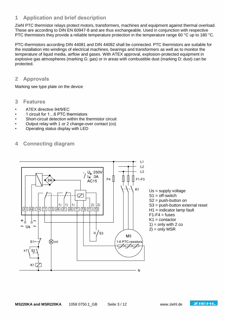
4 Connecting diagram
Us = supply voltage S1 = off-switch S2 = push-button on S3 = push-button external reset H1 = indicator lamp fault F1-F4 = fuses K1 = contactor 1) = only with 2 co 2) = only MSR
MS220KA and MSR220KA 1058 0750.1_GB Seite 4 / 12 www.ziehl.de
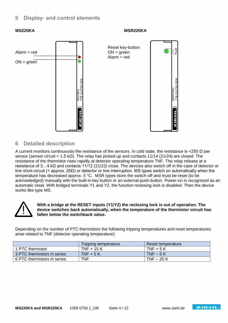
5 Display- and control elements
MS220KA MSR220KA
Reset key-button Alarm = red ON = green Alarm = red ON = green
6 Detailed description
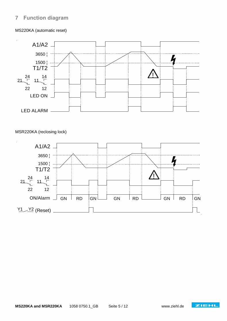
A current monitors continuously the resistance of the sensors. In cold state, the resistance is <250 Ω per sensor (sensor circuit < 1.5 kΩ). The relay has picked up and contacts 11/14 (21/24) are closed. The resistance of the thermistor rises rapidly at detector operating temperature TNF. The relay release at a resistance of 3…4 kΩ and contacts 11/12 (21/22) close. The devices also switch off in the case of detector or line short-circuit (< approx. 20Ω) or detector or line interruption. MS types switch on automatically when the temperature has decreased approx. 5 °C. MSR types store the switch-off and must be reset (to be acknowledged) manually with the built-in key button or an external push-button. Power-on is recognized as an automatic reset. With bridged terminals Y1 and Y2, the function reclosing-lock is disabled. Then the device works like type MS.
With a bridge at the RESET inputs (Y1/Y2) the reclosing lock is out of operation. The device switches back automatically, when the temperature of the thermistor circuit has fallen below the switchback value.
Depending on the number of PTC thermistors the following tripping temperatures and reset temperatures arise related to TNF (detector operating temperature):
Tripping temperature Reset temperature
1 PTC thermistor TNF + 15 K TNF + 5 K
3 PTC thermistors in series TNF + 5 K TNF – 5 K
6 PTC thermistors in series TNF TNF – 20 K
!
MS220KA and MSR220KA 1058 0750.1_GB Seite 5 / 12 www.ziehl.de
7 Function diagram
MS220KA (automatic reset) MSR220KA (reclosing lock)
1500 ¦
LED ON
3650 ¦
A1/A2
11
12
1421
22
24
LED ALARM
T1/T2
!
1500 ¦
(Reset)
ON/Alarm
3650 ¦
A1/A2
11
12
1421
22
24
T1/T2
!
Y1 Y2
RD RD RDGN GN GN GN GN
MS220KA and MSR220KA 1058 0750.1_GB Seite 6 / 12 www.ziehl.de
8 Installation / commissioning
Attention! Observe safety rules and standards. Notice safety remarks!
The applicant must observe safety rules and standards.
Danger! Hazardous voltage! Will cause death or serious injury. Turn off and lock out all power supplying this device before working on this device.
The device can be mounted on 35 mm rail according EN 60715 or with screws M4 (Option)
vertical connector block, width 22.7 mm
The devices must be installed in a closed switchgear cabinet or in an enclosure of international protection class IP 5x according EN 60529 or better.
When installing the device into the switchgear cabinet, please observe the max. admissible temperature. Care for both, sufficient clearance to other devices or sources of heat or enough forced draught. If cooling is made more difficult, e.g. close devices with increased surface temperature or by handicap of airflow cooling, the permissible ambient temperature has to be reduced.
Attention! Before switching on make sure that the operational voltage Us of the type plate and the mains voltage are the same!
After installation and before commissioning the correct function of the tripping device must be checked by resistance simulation at terminals T1 and T2. This check is also performed after changes to the installation.
9 Trouble – shooting and remedies
Relay does not pick up. Please check:
The supply voltage Us at terminals A1-A2 (green LED lights-up).
The PTC’s at terminals T1-T2. In the case of disturbance the red LED lights-up.
The resistance of a PTC circuit must be at 50 Ω < R < 1500 Ω. The terminal voltage T1-T2 is to be measured < 2.5 Vdc with connected PTC.
MSR types please push the key button “Reset”. The relay can pick up at resistance R < 1.65 kΩ and the key button light changes from red to green. Alternatively reset can be done with closing an external contact at terminals Y1-Y2 or with power recovery.
Relay does not release. Please check:
With no PTC sensor connected the relay must release. The voltage at terminals T1-T2 must be approx. 8 V.
In case of any other malfunctions, replace device. Please add a description of the occurred malfunction when sending back for repair.
!
!
MS220KA and MSR220KA 1058 0750.1_GB Seite 7 / 12 www.ziehl.de
10 Technical data
Power supply
Rated supply voltage Us AC 110-120 V AC 220-240 V (see type plate) AC 380-415 V
AC / DC 24 V (without UL marking) (without potentially separation)
Tolerance of voltage Us AC 0,9 Us -1,1 Us DC 21 ... 30 V Frequency (AC) 50 / 60 Hz Tolerance of frequency 45 - 65 Hz Power consumption < 2 VA
PTC thermistor connection
PTC thermistor acc. DIN 44081 / DIN 44082 Number 1 ... 6 PTCs in series Cut-out-point 3.3 kΩ…3.65 kΩ…3.85 kΩ Reclosing point 1.7 kΩ…1.8 kΩ …1.95 kΩ Response tolerance +/- 6° C Collective resistance cold thermistor ≤1.65 kΩ Terminal voltage (PTC thermistor) ≤ 2.5 V at R ≤ 3.65 kΩ
≤ 9 V at R =
Terminal current (PTC thermistor) < 1 mA Short circuit 20 Ω ≤ R ≤ 40 Ω Power consumption < 2 mW
Relay output EN 60947-5-1 Contacts 1 or 2 change-over contacts Switching voltage max. AC 415 V Switching current max. 5 A Switching power max. (ohm resistive load) 120 W at DC 24 V 1250 VA Rated operational current (Ie) AC15 Ie = 3 A Ue = 250 V DC13 Ie = 2 A Ue = 24 V Recommended fuse 4 A (gG) Mechanical contact life 3 x 10⁷ operations Electrical contact life 1 x 10⁵ operations at 240 V 5 A UL electrical ratings 250 V ac, 3 A, general use 240 V ac, 1/4 hp, 2.9 FLA 120 V ac, 1/10 hp, 3.0 FLA C 300
Testing conditions EN 60947 Rated impulse voltage 4000 V Overvoltage category III Contamination level 3 2 Rated insulation voltage Ui 250 V 415 V Transformer EN 61558-2-6 On-period 100 % Rated ambient temperature range -20 ... +55° C EMC - Immunity EN 61000-6-2 EMC - Emission EN 61000-6-3 Vibration resistance EN 60068-2-6 2…13.2 Hz ± 1 mm 13.2 ... 100 Hz 1 g
MS220KA and MSR220KA 1058 0750.1_GB Seite 8 / 12 www.ziehl.de
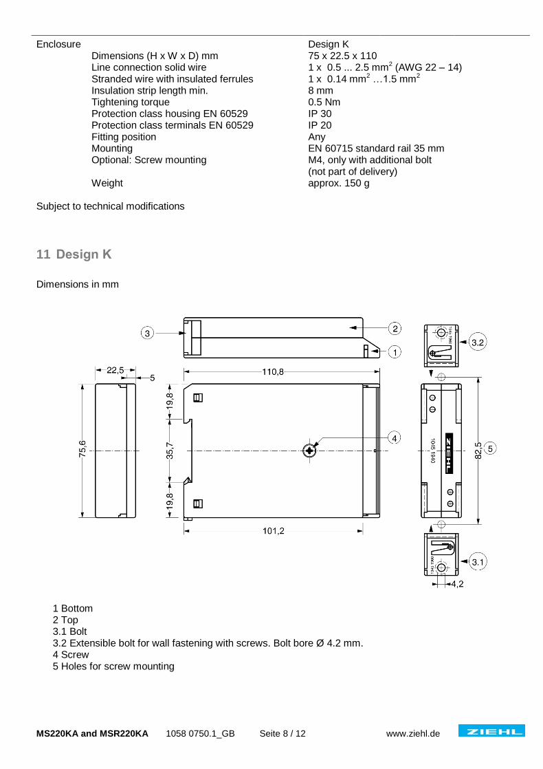
Enclosure Design K Dimensions (H x W x D) mm 75 x 22.5 x 110 Line connection solid wire 1 x 0.5 ... 2.5 mm2 (AWG 22 – 14) Stranded wire with insulated ferrules 1 x 0.14 mm2 …1.5 mm2 Insulation strip length min. 8 mm Tightening torque 0.5 Nm Protection class housing EN 60529 IP 30 Protection class terminals EN 60529 IP 20 Fitting position Any Mounting EN 60715 standard rail 35 mm Optional: Screw mounting M4, only with additional bolt
(not part of delivery) Weight approx. 150 g Subject to technical modifications
11 Design K
Dimensions in mm
1 Bottom 2 Top 3.1 Bolt 3.2 Extensible bolt for wall fastening with screws. Bolt bore Ø 4.2 mm. 4 Screw 5 Holes for screw mounting
MS220KA and MSR220KA 1058 0750.1_GB Seite 9 / 12 www.ziehl.de
12 Safety Instructions and references for putting into operation
– please read carefully!
12.1 Special remarks for explosive gas atmospheres areas (Zone 0, Zone 1 and Zone 2)
The increased danger within hazardous areas requires the careful attention of the safety instructions and references for putting into operation. Observe the national safety rules and regulations for prevention of accidents as well as the European Standard EN 60079-14 „Electrical apparatus for explosive gas atmospheres - Part 14: Electrical installations in hazardous areas (other than mines) “. All work for the connection, for putting into operation and maintenance is to be implemented by qualified, responsible technical personnel. Inappropriate behavior can cause heavy personal damage and damages to property.
The response of the thermal motor protection must directly switch off the motor, also when used together with converters. This must be realized in the logic section or configuration in the converter.
The tripping device may be installed only outside potentially explosive atmospheres for the protection of explosive-protected motors. When used in potentially atmospheres, the device must comply with the required type of protection.
12.2 Special remarks for use in the presence of combustible dust! (Zone 20, Zone 21 and Zone 22)
The increased danger within hazardous areas of combustible dust requires the careful attention of the safety instructions and references for putting into operation. Observe the national safety rules and regulations for prevention of accidents as well as the European Standard EN 61241-14 „Electrical apparatus for use in the presence of combustible dust – Part 14: Selection and installation” (new in EN 60079-14). Installation, electrical connection and commissioning to be carried out by trained service personnel only. Inappropriate behaviour can cause heavy personal damage and damages to property.
The tripping device may be installed only outside potentially explosive atmospheres for the protection of explosive-protected motors. When used in potentially explosive atmospheres, the device is to be provided with a dust proofed enclosure according EN 60529.
12.3 Safety characteristics of the safety device
Safety Integrity Level (EN 61508) and safety related parameters
Operating mode Hardware architecture HFT Safety Integrity Level
low demand mode 1001 0 SIL 1
Type MTBF PFH SFF SD SU DD DU
MS220KA 54 years 4.07E-07 55% 4.44E-07 5.55E-08 0 4.07E-07
MSR220KA 52 years 4.26E-07 55 % 4.52E-07 6.10E-08 0 4.26E-07
Type Proof test interval T1
1year 3 years 5 years 10 years
MS220KA PFDavg 1.78E-03 5.35E-03 8.91E-03 1.78E-02
MSR220KA PFDavg 1.87E-03 5.60E-03 9.33E-03 1.87E-02
Observe proof test interval according EN 60079-17 for electrical equipment ≤ 3 years.
!
MS220KA and MSR220KA 1058 0750.1_GB Seite 10 / 12 www.ziehl.de
12.4 Category and Performance-Level (EN ISO 13849-1)
The devices fulfil the requirements of category 1 and PL = c. MTTFd = 268 years. The data of the functional safety stated above are valid for an ambient temperature of 40 °C. Data for additional ambient temperatures can be obtained on request.
12.5 Application of the safety device used with equipment category (EN 50495/VDE 0171-18)
This standard describes the minimum requirements of safety integrity level and fault tolerance of a safety device in the application together with the category of the Equipment Under Control (EUC).
EUC Safety device
no safety device SIL 1 SIL 2
Category 2 (2G, 2D)
EPL = Gb, Db Zone 1, Zone 21 Zone 0, Zone 20 Zone 0, Zone 20
Category 3 (3G, 3D)
EPL = Gc, Dc Zone 2, Zone 22 Zone 1, Zone 21 Zone 0, Zone 20
The tripping relay thus is suitable as safety device for Equipment Under Control (EUC) Category 3 (HFT = 0) in Zone 1 and Zone 21 and for Equipment Under Control (EUC) Category 2 (HFT = 1) in Zone 0 and Zone 20. The combined equipment shall comply with the relevant standards EN 60079-0 respectively EN 61241 according to the categories to match.
12.6 Wiring
The lines of the thermistor circuit are to be routed as separate control lines as far as to the motor line. The use of lines of the supply cable or other mainstream lines is not permissible. If extreme inductive or capacitive stray effects are to be expected by parallel cables of the power installation, shielded control lines should be used.
Used with electronic speed regulation the thermistor lines must be routed separately from the power lines as far as to the motor line, in order to avoid EMC distortion and thus false signal release.
With devices type MSR the terminals Y1, Y2 may be attached parallel to a common resetting mechanism. Sensor lines may not be connected together.
The line resistance within the sensor circuit may not exceed a value of 20 Ω. Maximum of permissible length for sensor circuit lines:
Wire cross section Wire length
2,5 mm 2 2 x 1000 m
1,5 mm 2 2 x 800 m
1,0 mm 2 2 x 500 m
0,75 mm 2 2 x 300 m
0,5 mm 2 2 x 250 m
MS220KA and MSR220KA 1058 0750.1_GB Seite 11 / 12 www.ziehl.de
With commissioning and after modification of the plant the sensor resistance must be checked with a suitable measuring instrument. With a resistance < 50 Ω the sensor circuit is to be examined for short-circuit.
Attention! Check PTC’s only with measuring voltages of < 2.5 V.
12.7 Safe Separation
Line circuits (A1, A2, 11, 12, 14) have a safe separation to low-voltage electric circuits (T1, T2, Y1, Y2). Trip relays with supply voltage DC/AC 24 V are permissible only at power supplies according EN 61558-2-6 where protected wiring is used.
12.8 Stop function
A stop function released by the protection device must transfer the machine after manipulation of this function as fast as possible into a safe condition. The stop function must have top priority.
In case of failure the relay switches off the contactor/circuit breaker and so prevents an overheating of the isolation system and/or the surface temperature. The protective function of the equipment is guaranteed only if wiring is done directly into the control circuit of the motor/machine in accordance with the connection diagram. The contacts must be protected, in order to prevent welding.
12.9 Start and Restart
A restart may take place automatically only if no dangerous condition can be present. The tripping devices of types MS220KA are equipped with an automatic reset function. For this device design, suitable wiring of the control units must be ensured to prevent automatic restarting of the explosive-protected motor of the type of protection Increased Safety „e“ in case of failure.
Manual resetting
After introducing a stop instruction by the protection device this must be maintained, until the manual resetting mechanism is operated and safe conditions for a renewed start are given. The manual resetting may be only possible, if all safety functions and protection devices are effective.
Trip devices type MSR 220KA have an electronic reclosing lock. The stop instruction remains, until by pressing the push-button „Reset“ a reset is made. A start-up is only possible, if no case of failure occurs and the motor is cooled down to a sufficient value of temperature. Trip devices type MSR220KA switch on automatically with return of supply voltage. The user must guarantee by external interlock (see connection diagram) so the supervised motor/machine does not start again independently.
Attention! Safety circuits according to EN 60204/EN 62061. The tripping devices must not be used alone for functions, where an automatic Restart must be prevented.
!
!
!
MS220KA and MSR220KA 1058 0750.1_GB Seite 12 / 12 www.ziehl.de
13 Proof testing of the safety functions
The safety function shall be tested at regular intervals. It is recommended to carry out the proof-test once a year. Depending on the zone risk, tests should be conducted more frequently. A fault is recognized by the safety test. A fault between safety tests could cause loss of protection.
The safety function must be tested by interrupt the thermistor circuit wire at terminals T1, T2.
The short circuit monitoring function must be tested by bridging the thermistor circuit wires at terminals T1, T2.
The safety function must be tested by changing the resistance from 1500 Ohm to 4000 Ohm at terminals T1, T2.
The function of the electronic interlock must be tested additionally.
If an error is detected no restart must be induced until the error is cleared.
14 Maintenance and repair
The devices are maintenance-free. Only the manufacturer may accomplish repairs. We recommend testing within the regular maintenance intervals of the plant, where the device is used. EN 60079-17 is to be observed. You’ll find this and other user manuals in the internet under www.ziehl.com