openo&m use cases with scenarios and enabling technology · use cases with scenarios and...
TRANSCRIPT

OpenO&M Oil & Gas Industry
Use Cases with Scenarios and
Enabling Technology
Ken Bever
MIMOSA CTO
+1 (513) 276-4105
1

Use Cases
1 Handover Information from EPC to O/O
2 Engineering Upgrades to O&M
3 Field Changes to Plant/Facility Engineering
4 Up-to-Date Product Data Library (from On-line RDL)
5 O&M Asset Configuration Updates
6 Preventive Maintenance Triggering
7 (Semi-) Automatic Triggering of Condition Based
Maintenance (CBM)
8 Early Warning Notifications
9 Incident Management/Accountability
10 Information Provisioning of O&M Systems2

Systems Requiring Interoperability
AHMS Asset Health Management System MES Manufacturing Execution System
CIR Common Interoperability Registry MMS Maintenance Management System
CMS Condition Monitoring System OPM Operational Performance Modelling &
Optimization System
DCS Distributed Control System ORM Operational Risk Management System
DMS Document Management System PDM Product Data Management System
EAM Enterprise Asset Management System PLC Programmable Logic Controller
ENG Engineering Schematic Topology and
Instrumentation Tag Configuration Management
System
PORT Enterprise KPI/Event Portal
ERM Enterprise Risk Management System PSMS Process Safety Management System
ERP Enterprise Resource Planning System QMS Quality Management System
HMI Human-Machine Interface (Operator Console)
System
REG O&M Product, Structure, Asset Registry with
Standardised Data Dictionary and Taxonomy
ISBM Information Service Bus Model SCADA Supervisory Control and Data Acquisition
LIMS Lab Information Management System SHES Safety, Health, and Environmental System
3

NOTE: Arrows with Do Not
Connect Directly to Another
System Publish Information
Which Can Be Subscribed to
By Multiple Systems
Open Standards Which Define Data Content for Information Exchange
OAGIS, CIDX
OpenO&M Common Interop. Registry
ISO 15926 / iRING
B2MML
B2MML & PRODML
MIMOSA, B2MML & PRODML
MIMOSA
OPC
Fieldbus (Foundation, Profibus, etc.)
OpenO&M Systems Landscape Data Flow
Diagram with Use Case Scenarios
4


7
1 27
15
17
16
18
25
29 30
23
24
12
13
14
20
19
22
21
31
10
8 26
2 28
4 5 11
3 6 9

Scenarios
7
No. Method Data From System To System
1 PublishAs-Designed/As-Built Engineering
Network/Segment/TagENG REG-STRUCTURE
2 PublishAs-Designed/As-Built Engineering
Network/Segment/TagREG-STRUCTURE O&M
3 Publish As-Maintained Engineering Network/Segment/Tag O&M O&M
4 Publish As-Built Engineering AssetENG,
CONSTRUCTREG-ASSET
5 Publish As-Built Engineering Asset REG-ASSET O&M
6 Publish As-Maintained Engineering Asset O&M O&M
7 Pull OEM Model OEM PDM REG-PRODUCT
8 Pull OEM Model REG-PRODUCT O&M
9 Publish OEM Model O&M O&M
10 Push Asset Removal/Installation CMS MMS
11 Publish Asset Removal/Installation MMS O&M

Scenarios (cont.)
8
No. Method Data From System To System
12 Pull Usage Readings CONTROL MMS, ORM
13 Publish Usage Readings CONTROL MMS, ORM
14 Push CBM Advisories ORM MMS
15 Pull Maintenance Work Status/Work History MMS O&M
16 Publish Maintenance Work Status/Work History MMS O&M
17 Pull Maintenance KPIs MMSERP, ERM, PORT,
MES, OPM
18 Publish Maintenance KPIs MMSERP, ERM, PORT,
MES, OPM
19 Pull Performance KPIs ORMERP, ERM, PORT,
OPM
20 Publish Performance KPIs ORMERP, ERM, PORT,
OPM
21 Pull Significant ORM Events ORMERP, ERM, PORT,
OPM
22 Publish Significant ORM Events ORMERP, ERM, PORT,
OPM

Scenarios (cont.)
9
No. Method Data From System To System
23 Pull OPM KPIs OPMERP, ERM, PORT,
MES
24 Publish OPM KPIs OPMERP, ERM, PORT,
MES
25 Publish Product/Part Engineering Change Advisories OEM PDM REG-PRODUCT
26 Publish Product/Part Engineering Change Advisories REG-PRODUCT O&M
27 Publish Plant/Process Change Advisories ENG REG-STRUCTURE
28 Publish Plant/Process Change Advisories REG-STRUCTURE O&M
29 Pull Current Operating Data and Events CMSCONTROL, ORM,
OPM
30 Publish Current Operating Data and Events CMSCONTROL, ORM,
OPM
31 Pull Historical Operating Data and Events HIST ORM, OPM

OpenO&M Systems Landscape Data Flow
Diagram with Use Case 1 scenarios
10
1
4

Use Case 1 – Handover EPC to O/O
• Handover of As-Designed, As-Engineered and As-Built Information from Engineering, Procurement, and Construction (EPC) Contractor(s) to Owner/Operator – A core problem for Owner/Operators (O/O), vendors and systems implementers is the lack of good mechanisms for managing the needed information exchanges between EPC activities and the O&M related systems, applications and technologies.
• Information to Be Exchanged: Information is needed to properly bootstrap O&M systems with as-designed functional segment data (including P&ID diagram information of network topologies, breakdown structures and process/equipment data sheets), and asset and installation data. Need to have access to “tag” databases which identify where sensors have been installed for control and monitoring, related to the process equipment they are monitoring, and the meta-data about them (tag ID, update frequency, engineering unit, etc.).
• Scenarios Activated: 1, 4
11

Use Case 1 – Handover EPC to O/O
Scenarios
• The first scenario is (2) Publish As-Designed / As-Built Engineering Network / Segment / Tag data from REG-STRUCTURE to O&M. This scenario details the batch exchange of structural design information that forms part of the registry master data required by most O&M systems. This information originates from the Structural Registry (which stores Plant Breakdown Structures, Logical P&IDs and PFDs) and is sent to all applicable O&M systems.
• The second scenario is (5) Publish As-Built Engineering Asset data from REG-ASSET to O&M. This scenario is similar to the previous, but details the exchange of asset and installation information. This information originates from the Asset Registry and is sent to all applicable O&M systems.
12

Use Case 2 – Engineering Upgrades
• Recurring Updates – Send Open Engineering Upgrades to O&M: Once a site is operational, plant or facility engineering and design organizations may continue to make changes to the as-designed information models on a recurring basis. These changes can be driven by the need to operate more efficiently or with greater safety in support of the originally intended process supporting the same product mix or they can be associated with the need to change the process to yield new products, not envisioned in the original design. Once the new design information is developed it may be managed in several different ways depending on the driver for the change and the associated priority it will be assigned. Depending on the nature and scale of the changes involved, the actual work may be performed by the maintenance staff, a maintenance contractor or a construction contractor. In all cases, some type of appropriate feedback loop must be provided to ensure that the status is known and shared by Engineering Reference Databases and O&M systems.
• Information to Be Exchanged: Need to propagate changes to functional segment data, including P&ID diagram information related to process/equipment data sheets with guaranteed delivery despite network hiccups.
• Scenarios Activated: 1, 2, 4, 5
13

Use Case 3 – Field Changes
• Field Engineering – Changes Sent To Plant or Facilities Engineering: In a perfect
world, fully leveraging best practices, all engineering changes would flow through the
enterprise design engineering and approval systems on a “waterfall” basis, even if the
actual design work is done locally or through an independent contractor. All such
engineering changes would be fully reconciled and rationalized before the work was
actually done and the integrity of the Engineering Reference Databases would be ensured
as a specialization of use case 2. Unfortunately, there are many situations where this does
not occur (and may be impractical). This frequently results when a centralized plant or
facilities engineering organization is overwhelmed by emergent situations and the plant or
facilities manager must take responsibility for the situation without the ideal level of
centralized support. Lack of proper synchronization of this work can result in anomalies
with respect to the system of record for the engineering information, since in this case, the
most up-to-date as-designed information is flowing from the field to the enterprise, rather
than the other way around.
• Information to Be Exchanged: The information is very similar to that which is contained
in Use Case 2, but it now needs to flow from the field to the Engineering Reference
Database so that the systems can be kept in sync. Need to propagate changes to
functional segment data, including P&ID diagram information related to process/equipment
data sheets with guaranteed delivery despite network hiccups.
• Scenarios Activated: 3, 6
14

Use Case 4 – Online Product Data
• Open On-line Product Data Library: All of the Use Cases contained in this document anticipate the on-line availability of appropriate product data libraries containing the detailed engineering reference information for makes and models of important classes of physical assets. Critical elements of ERM including both Operational Risk Management (ORM) and EH&S depend on the Enterprise Asset Management (EAM), Reliability Management (RM), Condition Based Maintenance (CBM) and ORM systems leveraging the most current product data. Manufacturers are often reluctant to publish some quality and reliability data about their products which is extremely important and this information needs to be gathered from trusted third parties and/or internal operating experience. As this new experience-based information becomes available, it also needs to be properly persisted and synchronized.
• Information to Be Exchanged: For all key originally installed and replaced equipment, ORM and EAM systems need on-line access to motor/pump/gear/bearing/valve/sensor OEM cut-sheet specification data in order for ORM systems to perform equipment diagnostics, validate current configurations meet the required process requirements, and for EAM systems to display to maintenance personnel. ORM and EAM systems need to know if this data is subsequently updated/modified to adjust algorithms with guaranteed delivery. ORM and EAM systems also need to ability to transfer newly-discovered product data into the PDM master database.
• Scenarios Activated: 7, 8, 9, 25, 26
15

Use Case 5 – Asset Updates
• Automatic O&M Configuration (Remove/Replace) Updates: One of the largest headaches for any complex facility or plant is keeping accurate track of the uniquely identified physical assets which are currently installed in a given functional location. Use Cases 1 and 2 deal with “top-down” Design Engineering-driven activities and Use Case 3 deals with the situation where this is a “bottom-up” process, but routine remove/ replace operations are work flow-driven rather than design-driven.
• While all organizations make an attempt to properly keep track of this information for classes of assets with critical functions, experience has shown that substantial process and information gaps routinely exist. After a few years of operations, there is often a substantial difference between the assets that are shown to be installed in the system of record and those that actually are installed. This situation is normally verified and at-least partially corrected when a “walk down” takes place in conjunction with the implementation of some new related system (such as an EAM system). This is an expensive, labor intensive process and it does not solve the fundamental problem, which results in its recurrence. Lack of proper management of this seemingly straight-forward element of configuration change can have profound consequences for reliability, EH&S, quality, and yield.
• Information to Be Exchanged: When a fieldbus device is replaced and a CMS system is able to sense that a new device has been removed/installed, it should immediately update the registry (REG) system of this configuration change, which should then be propagated to all other O&M systems. When data is keyed into an EAM system that an asset removal and/or installation has taken place, it should immediately update the registry (REG) system of this configuration change, which should then be propagated to all other O&M systems with guaranteed delivery despite any potential network connectivity and/or latency problems.
• Scenarios Activated: 10, 11
16

OpenO&M Systems Landscape Data Flow
Diagram with Use Case 5 scenarios
17
10
11

Use Case 5 – Handover EPC to O/O
Scenarios
• The first scenario is (10) Push Asset Removal/Installation data from CMS to MMS. This scenario details the sensing
of an asset removal/installation at a functional location and
subsequent notification by a condition monitoring system to
a maintenance management system.
• The second scenario is (11) Publish Asset Removal/Installation data from MMS to O&M. In order to
notify other O&M systems that a serialized asset has been
replaced, the maintenance management system publishes
an asset change event to all relevant O&M systems.
18

Use Case 6 – Automatic PMs
• Open Automatic Preventive Maintenance (PM) Triggering: While there has sometimes been confusion between automated triggering of PM and the evolving trend to use more Condition Based Maintenance (CBM), PM, along with Corrective Maintenance (CM) continue to be part of the “Maintenance Mix”, with the appropriate use of each to be dictated by a maintenance strategy properly linked to ERM. Parts of this linkage are normally established through an engineering practice known as Reliability Centered Maintenance (RCM), but comprehensive linkage to the ERM process has not been routine to the degree which will be increasingly required.
• PM procedures are normally setup to be performed based on the passage of time, some sort of meter-based utilization record (such as miles driven) or a combination of the two. PM procedures must often be performed as part of a manufacturer’s warranty requirements or to meet external regulator agency requirements. While PM is expected to slowly decline in favor of CBM, it is still critical for systems that rely on it and it is often too easy to miss a PM that is required by utilization. PM, CBM and CM are often interrelated when a PM procedure is setup to trigger an inspection route work order which may subsequently result in either a CM or CBM activity. Proper integration with the controls and/or plant data historian environment enables the usage information to be captured for automatic PM triggering. The EAM system must be able to compare the newly proposed PM event to any pre-existing events to avoid generating multiple work orders for the same requested activity, but the individual request must enable a linkage with an audit trail from each requesting system (Agent).
• Information to Be Exchanged: In order to allow PM activities which are usage-based to be triggered at the appropriate time without manual entering of readings and to assist ORM systems which have usage logic included in their diagnostics/prognostics, then there is a need to automatically transfer usage readings captured on certain equipment from the Historian system to the EAM system (for PM-triggering) and ORM systems (for CBM-triggering).
• Scenarios Activated: 12, 13, 29, 31 19

Use Case 7 – CBM Triggering
• Open Automatic or Semi-Automatic CBM Triggering: The benefits of interoperability start to pay significant dividends when the near-real time decision support systems (such as ORM) begin to properly interact with the transaction processing oriented business systems (such as EAM) based on data/information feeds from true real-time systems involved in monitoring and control. While it is fairly easy to show a hierarchy of data/information/knowledge on a PowerPoint slide, the nature of the use cases needs to be fully contemplated when the transforms are taking place as part of the systems interaction scenarios. This involves several categories of systems spanning 3 basic layers (real-time, near real-time and transaction processing) in the interoperability stack and they are normally provided by several communities of solutions providers, with multiple vendors in each community. Providing sustainable interoperability for all of these systems of systems is a critical focal-point for open standards based interoperability.
• This use case does NOT assume interaction with operations planning and scheduling oriented systems. It is limited to the current practice where specialized maintenance, reliability, quality and safety systems are able to diagnose or prognose a need for a maintenance action. When an ORM system (PSMS, AHMS, QMS, EMS) determines that a maintenance action is required; it must be able to generate a CBM-driven request for action/work advisories using an open interface to an EAM system. The ORM should be smart enough to check beforehand to see if similar maintenance work entries are outstanding on an asset so as not to “flood” an EAM system with the exact same CBM request for action/work. In addition, the ORM system needs to be able to check the status of the work submitted.
• Information to Be Exchanged: All information required to generate a CBM request for action/work.
• Scenarios Activated: 14, 15, 16, 29 ,30, 31
20
Use Case 8 – Early Warnings
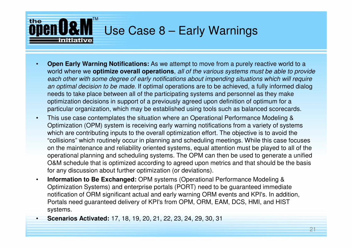
• Open Early Warning Notifications: As we attempt to move from a purely reactive world to a
world where we optimize overall operations, all of the various systems must be able to provide
each other with some degree of early notifications about impending situations which will require
an optimal decision to be made. If optimal operations are to be achieved, a fully informed dialog
needs to take place between all of the participating systems and personnel as they make
optimization decisions in support of a previously agreed upon definition of optimum for a
particular organization, which may be established using tools such as balanced scorecards.
• This use case contemplates the situation where an Operational Performance Modeling &
Optimization (OPM) system is receiving early warning notifications from a variety of systems
which are contributing inputs to the overall optimization effort. The objective is to avoid the
“collisions” which routinely occur in planning and scheduling meetings. While this case focuses
on the maintenance and reliability oriented systems, equal attention must be played to all of the
operational planning and scheduling systems. The OPM can then be used to generate a unified
O&M schedule that is optimized according to agreed upon metrics and that should be the basis
for any discussion about further optimization (or deviations).
• Information to Be Exchanged: OPM systems (Operational Performance Modeling &
Optimization Systems) and enterprise portals (PORT) need to be guaranteed immediate
notification of ORM significant actual and early warning ORM events and KPI's. In addition,
Portals need guaranteed delivery of KPI's from OPM, ORM, EAM, DCS, HMI, and HIST
systems.
• Scenarios Activated: 17, 18, 19, 20, 21, 22, 23, 24, 29, 30, 31
21

Use Case 9 – Incident Accountability
• Incident Management: With the increasing emphasis on risk management topics including
Operational Risks and Health, Safety and Environmental risks, better incident management
methods must be established. While traditional incident management systems relied on
somewhat arbitrary (and frequently manual) methods to declare, capture, escalate and
respond to various categories of incidents, a more systemic approach enables a substantially
improved approach to risk management. Post mortem analysis shows that in many cases, a
catastrophic event is proceeded by a series of improperly captured and escalated incidents.
When the catastrophe occurs, management often responds by indicating they were unaware
of the situation in spite of prior related incidents. In response, regulatory agencies such as
OSHA are communicating their intent to hold management increasingly accountable
(including criminal prosecution) for future catastrophes with ignorance to not be an excuse. In
order to enable management to be properly aware of these incidents (in addition to the other
risk indicators flowing in association with use case 8), industry must make sure that critical
information is captured and escalated along the lines of accountability. An automated
approach offers the greatest assurance of such a flow by eliminating unnecessary gaps in the
process. This will also properly support the forthcoming requirements to capture, track and
report “near-miss” incidents.
• Information to Be Exchanged: Enterprise Risk Management Systems must be guaranteed
delivery of actual and near miss incidents as they are declared and captured at the lowest
practical level in the data/information “food chain”. They can then escalate and manage the
incidents bases upon previously defined rules.
• Scenarios Activated: 21, 22, 29, 30, 31 22

Use Case 10 – O&M Provisioning
• Data Enrichment and Provisioning of O&M Systems – The data required for O&M systems goes beyond the data set the EPC provides. For example, maintenance hierarchies are defined externally (e.g. by the O/O or a maintenance contractor) and not by an EPC, although the hierarchy may reference EPC data elements. The EPC turnover data in the O&M Register is therefore enriched before information provisioning for each O&M system.
• Information to Be Exchanged: Information is needed to properly bootstrap O&M systems with as-designed functional segment data (including P&ID diagram information of network topologies, breakdown structures and process/equipment data sheets), and asset and installation data. Need to have access to “tag” databases which identify where sensors have been installed for control and monitoring, related to the process equipment they are monitoring, and the meta-data about them (tag ID, update frequency, engineering unit, etc.).
• Scenarios Activated: 2, 5
23

OpenO&M Systems Landscape Data Flow
Diagram with Use Case 10 scenarios
24
5
2

Use Case 10 – O&M Provisioning
Scenarios
• The first scenario is (2) Publish As-Designed / As-Built Engineering Network / Segment / Tag data from REG-STRUCTURE to O&M. This scenario details the batch exchange of structural design information that forms part of the registry master data required by most O&M systems. This information originates from the Structural Registry (which stores Plant Breakdown Structures, Logical P&IDs and PFDs) and is sent to all applicable O&M systems.
• The second scenario is (5) Publish As-Built Engineering Asset data from REG-ASSET to O&M. This scenario is similar to the previous, but details the exchange of asset and installation information. This information originates from the Asset Registry and is sent to all applicable O&M systems.
25

26
control systems,
operational data
historians & hmi’s
OPC &
MIMOSA OSA-EAI
operational forecasting,
planning & scheduling
systems
ISA-95 WBF B2MML
order/mission mgt..,
material mgt., personnel &
financial systems (ERP)
OAGi
OpenO&M Information Service Bus & OpenO&M Common Interoperability Registry
MIMOSA OSA-EAI
periodic & online
condition monitoring
systems, diagnostic /
prognostic asset health
system
o&m system topology
& tag registries, asset
registry with
configuration
management
MIMOSA OSA-EAI
maintenance work
management
MIMOSA OSA-EAI
well information,
drill/well production
reporting
Energistics PRODML
& WITSML
OpenO&M Approach –Each System Engineered to Speak a Common O&M Language over a Common Information BusWith a Common Interoperability Registry
OEM product specification
data & EPC system
engineering design
requirements
ISO 15926

Enabler: OpenO&M
Common Interoperability Registry (CIR)
Enabler: OpenO&M
Common Interoperability Registry (CIR)

EPC P&ID Requirements&OEM Product Data
Control Systems, Data Historians, Condition Monitoring, & SHE Systems Data
Enterprise HR, Financial,
Materiel, Logistics, &Mission Capability Data
Maintenance Breakdown Structure, Maintenance Work Plans, & Actual Failure Data
Production Optimization, Planning & Scheduling
Oil & Gas Portals / Business Applications
Business Intelligence
O&M Requirements Repository
O&M Registry
OpenO&M Information Service Bus

OpenO&M Common Interoperability Registry
(CIR)
• Provides the “Yellow-Pages” lookup for all systems to locate
an identical object in another system
• Glue to tie systems together which have different Identifiers
for the exact same object but never had to talk “on-line”
before
• Provides a globally-unique CIR Identifier (CIR Id) to link
“local” object IDs

OpenO&M Common Interoperability Registry UML Model
class OM CIR Model V0.5
CIRRegistry
+ ID: IdentifierType
+ GUID: UUIDType
- userDescription: TextType [0..n]
Examples
========
Registration Server A
Test Registry
Finance System Registry
OpenO&M Common Interop Registry (CIR) Model
Copyright 2009. MIMOSA and World Batch Forum (WBF).
All Rights Reserved. http://www.openoandm.org
Release 0.4 (21-Apr-09)
1

CIRRegistry A CIRRegistry object is the container object for a set of registration categories. Examples of
multiple registries include: test registry, active registry, local site registry, global corporate
registry.
ATTRIBUTES
Attribute Description Restrictions
ID User supplied ID of the registry. This must be
unique within the registry server.
Required
GUID System assigned globally unique ID for the
registry. This is unique across all registry
servers.
Required
userDescription User description of the registry and expected
use of the registry.
Multiple values allowed
for multiple languages or
alternate descriptions
OpenO&M Common Interoperability Registry UML Model

class OM CIR Model V0.5
CIRRegistryEntry
+ entityIDinSource: IdentifierType
+ sourceID: IdentifierType
CIRRegistryCategory
+ ID: IdentifierType
+ categorySourceID: IdentifierType
+ userDescription: TextType [0..1]
+ ISO15926ObjectReferenceURI: IdentifierType [0..n]
categorySourceID Examples
========================
MIMOSA CRIS V3.3
BatchStatus
ISA95.EquipmentModel2000
B2MML.EquipmentModel
ISA88.RecipeModel1995
BatchML.RecipeModelV4.04.01
ChemCompany.RefineryModelV2.1
ShippingCompany.TransportCode
Examples
=================
OpenO&M Registry Entry
Asset
Asset_Type
Segment
Segment_Type
Meas_Location
Meas_Loc_Type
Network
Network_Type
P&ID Diagram Object
Batch Status
Production Status
Equipment Status
CIRRegistry
+ ID: IdentifierType
+ GUID: UUIDType
- userDescription: TextType [0..n]
Examples
========
Registration Server A
Test Registry
Finance System Registry
OpenO&M Common Interop Registry (CIR) Model
Copyright 2009. MIMOSA and World Batch Forum (WBF).
All Rights Reserved. http://www.openoandm.org
Release 0.4 (21-Apr-09)
0..*
are
composed
of
1
0..*
1
OpenO&M Common Interoperability Registry UML Model

CIRCategory A CIRCategory object is the container object for a set of registry entries. Registry categories
define sets of related, or potentially related registry entries. For example, a registry category may
be defined for equipment hierarchy level names (Enterprise, Site, Area, Work Center, Work
Unit), which have alternate names on different systems. The combination of ID and
categorySourceID must be unique.
ATTRIBUTES
Attribute Description Restrictions
ID User supplied ID of the category Required
categorySourceID Identification of the category. May define the
organization and specification name for the
category, for example:
• MIMOSA OSA-EAI V3
• ISA 88 BatchStatus
• ISA 95-2000 EquipmentModel
• B2MML.EquipmentModel
• ISA88.RecipeModel1995
• BatchML.RecipeModelV4.04.01
• ChemCompany.RefineryModelV2.1
• ShippingCompany.TransportCode
Required
userDescription User description of the category and expected
use of the category
Multiple values allowed
for multiple languages or
alternate descriptions
ISO15926ObjectRe
ferenceURI
Defines the associated part of the ISO 15926
that defines the registry category.
Optional
OpenO&M Common Interoperability Registry UML Model

CIRRegistryEntry
+ entityIDinSource: IdentifierType
+ sourceID: Identi fierType
+ CIRID: UUIDType [0..1]
+ sourceOwnerID: IdentifierType [0..1]
+ userDescription: TextType [0..n]
+ userTag: CodeType [0..1]
+ inActive: IndicatorType [0..1]
CIRRegistryCategory
+ ID: IdentifierType
+ categorySourceID: IdentifierType
+ userDescription: TextType [0..1]
+ ISO15926ObjectReferenceURI: IdentifierType [0..n]
categorySourceID Examples
========================
MIMOSA CRIS V3.3
BatchStatus
ISA95.EquipmentModel2000
B2MML.EquipmentModel
ISA88.RecipeModel1995
BatchML.RecipeModelV4.04.01
ChemCompany.RefineryModelV2.1
ShippingCompany.TransportCode
sourceOwnerID
Examples
=================
Oil Company A
Chem Company B
System Supplier A
System Supplier B
Examples
=================
OpenO&M Registry Entry
Asset
Asset_Type
Segment
Segment_Type
Meas_Location
Meas_Loc_Type
Network
Network_Type
P&ID Diagram Object
Batch Status
Production Status
Equipment Status
CIRRegEntry Examples
CIRID enti tyIDinSource userTag
================================== ============= =======
550e8400-e29b-41d4-a716-446655440000 234443 Loop 106
550e8400-e29b-41d4-a716-446655440000 423ABC Cmn Loop 106
550e8400-e29b-41d4-a716-446655440000 TIC-106 Top Temp Control
550e8400-e29b-41d4-a716-446655448778 TIC-8106 Top Temp Control
sourceID Examples
===============================
Engineering DB #234
Supplier A MIMOSA CRIS Registry Database #1
EAM/CMMS System B
0..*
have
1
0..*
are
composed
of
1
OpenO&M Common Interoperability Registry UML Model

CIRRegistryEntry A CIRRegistryEntry object defines a registry entry. Registry entries define named element and
properties with an identifier local to the owning application and a possible global ID (CIRID) that
defined equivalent entries in other applications.
For example the tag TC101 in system A may be the equivalent of tag UNIT101.TOP_TEMP in
system B.
The assumption is that the combination of entityIDinSource and sourceID form a unique
composite key within a registry category.
ATTRIBUTES
Attribute Description Restrictions
entityIDinSource User defined identification of the entry in
the source system
Required
Unique within the source
system
sourceID Identification of the source system Required
CIRID System assigned globally unique ID for the
entry
Optional
sourceOwnerID Organization that has responsibility for the
source system or entity name space
Optional
userDescription User description of the entry Multiple values allowed
for multiple languages or
alternate descriptions
userTag Shortcut identification of the entry, may not
be unique within the source system.
Optional
inActive Flag, if FALSE or missing indicates the
entry is active and available for use.
Examples of inactive entries may be data
that is entered but the source system is not
yet available or in use.
Optional
OpenO&M Common Interoperability Registry UML Model

OpenO&M CIR“ID”
• The OpenO&M Common Interoperability Registry ID (CIRID) must be generated in compliance with the Universal Unique IDentifier (UUID) definition found in ISO/IEC 11578:1996 "Information technology – Open Systems Interconnection – Remote Procedure Call (RPC)"
• A UUID is a 16-byte (128-bit) number. The number of theoretically possible UUIDs is therefore 216*8 = 2128 = 25616 or about 3.4 × 1038. To understand the quantity which this represents, 1 trillion UUIDs would have to be created every nanosecond for slightly more than 10 billion years to exhaust the number of UUIDs.
• In its canonical form, a UUID consists of 32 hexadecimal digits, displayed in 5 groups separated by hyphens, in the form 8-4-4-4-12 for a total of 36 characters(32 digits and 4 '-'). For example:
550e8400-e29b-41d4-a716-446655440000

CIRRegistryEntry
+ entityIDinSource: IdentifierType
+ sourceID: IdentifierType
+ CIRID: UUIDType [0..1]
+ sourceOwnerID: IdentifierType [0..1]
+ userDescription: TextType [0..n]
+ userTag: CodeType [0..1]
+ inActive: IndicatorType [0..1]
CIRProperty
+ ID: IdentifierType
+ currentValue: CIRValueType [0..*]
+ dataType: CodeType [0..1]
+ UOM: CodeType [0..1]
+ mandatory: IndicatorType [0..1]
ShippingCompany.TransportCode
sourceOwnerID
Examples
=================
Oil Company A
Chem Company B
System Supplier A
System Supplier B
P&ID Diagram Object
Batch Status
Production Status
Equipment Status
CIRRegEntry Examples
CIRID entityIDinSource userTag
================================== ============= =======
550e8400-e29b-41d4-a716-446655440000 234443 Loop 106
550e8400-e29b-41d4-a716-446655440000 423ABC Cmn Loop 106
550e8400-e29b-41d4-a716-446655440000 TIC-106 Top Temp Control
550e8400-e29b-41d4-a716-446655448778 TIC-8106 Top Temp Control
sourceID Examples
===============================
Engineering DB #234
Supplier A MIMOSA CRIS Registry Database #1
EAM/CMMS System B
Entity to store a small subset of properties that may be needed to l ink systems
together. It is not intended to be a global property master registry. The properties
may help in identification of equivalent entries. There are two predefined properties:
• CiRParentEntityID : Has the entityIDinSource for the parent object in the
source's hierarchy.
• CIRChildEntityID: Has the set of entityIDinSource for the child objcts in the
source's hierarchy.
0..*
have
1
0..*of
OpenO&M Common Interoperability Registry UML Model

CIRProperty A CIRProperty object defines a property of a registry entry. Properties may be used to help
identify equivalent registry entries. The properties should be a small set of properties that may be
needed to link systems together, and not intended to be a global property master registry.
There are two predefined properties that should be used to identify an entry’s position in a
source’s hierarchy:
1. CIRParentEntityID: Has the entityIDinSource for the parent object in the source's
hierarchy.
2. CIRChildEntityID: Has the set of entityIDinSource for the child objects in the source's
hierarchy.
ATTRIBUTES
Attribute Description Restrictions
ID User defined identification of the property Required
Unique within the list of
entry properties
currentValue Current value of the property Optional
Multiple values with value
key to provide for alternate
values for identification
dataType Data type of the current value Optional
UOM Unit of measure of the current value Optional
mandatory Flag that indicates if a value is required Optional
OpenO&M Common Interoperability Registry UML Model

class OM CIR Model V0.5
CIRRegistryEntry
+ entityIDinSource: IdentifierType
+ sourceID: IdentifierType
+ CIRID: UUIDType [0..1]
+ sourceOwnerID: Identi fierType [0..1]
+ userDescription: TextType [0..n]
+ userTag: CodeType [0..1]
+ inActive: IndicatorType [0..1]
CIRProperty
+ ID: Identi fierType
+ currentValue: CIRValueType [0..*]
+ dataType: CodeType [0..1]
+ UOM: CodeType [0..1]
+ mandatory: IndicatorType [0..1]
CIRRegistryCategory
+ ID: Identi fierType
+ categorySourceID: IdentifierType
+ userDescription: TextType [0..1]
+ ISO15926ObjectReferenceURI: Identi fierType [0..n]
categorySourceID Examples
========================
MIMOSA CRIS V3.3
BatchStatus
ISA95.EquipmentModel2000
B2MML.EquipmentModel
ISA88.RecipeModel1995
BatchML.RecipeModelV4.04.01
ChemCompany.RefineryModelV2.1
ShippingCompany.TransportCode
sourceOwnerID
Examples
=================
Oil Company A
Chem Company B
System Supplier A
System Supplier B
Examples
=================
OpenO&M Registry Entry
Asset
Asset_Type
Segment
Segment_Type
Meas_Location
Meas_Loc_Type
Network
Network_Type
P&ID Diagram Object
Batch Status
Production Status
Equipment Status
CIRRegEntry Examples
CIRID enti tyIDinSource userTag
================================== ============= =======
550e8400-e29b-41d4-a716-446655440000 234443 Loop 106
550e8400-e29b-41d4-a716-446655440000 423ABC Cmn Loop 106
550e8400-e29b-41d4-a716-446655440000 TIC-106 Top Temp Control
550e8400-e29b-41d4-a716-446655448778 TIC-8106 Top Temp Control
sourceID Examples
===============================
Engineering DB #234
Supplier A MIMOSA CRIS Registry Database #1
EAM/CMMS System B
Entity to store a small subset of properties that may be needed to link systems
together. It is not intended to be a global property master registry. The properties
may help in identification of equivalent entries. There are two predefined properties:
• CiRParentEntityID : Has the entityIDinSource for the parent object in the
source's hierarchy.
• CIRChildEntityID: Has the set of entityIDinSource for the chi ld objcts in the
source's hierarchy.
CIRRegistry
+ ID: IdentifierType
+ GUID: UUIDType
- userDescription: TextType [0..n]
Examples
========
Registration Server A
Test Registry
Finance System Registry
OpenO&M Common Interop Registry (CIR) Model
Copyright 2009. MIMOSA and World Batch Forum (WBF).
All Rights Reserved. http://www.openoandm.org
Release 0.4 (21-Apr-09)
0..*
have
1
0..*
are
composed
of
1
0..*
1
OpenO&M Common Interoperability Registry UML Model

UNCEFACT Core Components
• UN/CEFACT Core Component Types
• The base types for most OpenO&M and MIMOSA XML Schema elements are derived from core component types that are compatible with the UN/CEFACT core component types. The UN/CEFACT core component types are a common set of types that define specific terms with semantic meaning (e.g. the meaning of a quantity, currency, amount, identifier,…). The UN/CEFACT core components were defined in a Core Components Technical Specification (CCTS) developed by the ebXML project now organized by UN/CEFACT and ISO TC 154.
• The core components use several international standards for the representation of semantic and standardized information:
Name Standard
Country Code ISO 3166.1
Region Code ISO 3166.2
Language Code ISO 639: 1988
Currency Code ISO 4217
Date and Time Representation ISO 8601
Unit Of Measure Code UN/ECE Recommendation 20
Unit of Transport or Packaging Code UN/ECE Recommendation 21

AmountType is used to define a number of monetary units specified in a currency where the unit of currency is explicit or implied. It is derived from a decimal. Optional Attribute Base XML Type Description
currencyID normalizedString An identifier specifying the identification of a currency code. Reference UN/ECE Rec 9, using 3-letter alphabetic codes, also available as ISO 4217.
currencyCodeListVersionID normalizedString An identifier specifying the version of the currency code. The version of the UN/ECE Rec.9 code list.
UNCEFACT Core Components

BinaryObjectType is used to define a data types representing graphics, pictures, sound, video, or other forms of data that can be represented as a finite length sequence of binary octets. It is derived from base64Binary. Optional Attribute Base XML Type Description
format string The format of the binary content. No identifiers for standard formats are defined.
mimeCode normalizedString The mine type of the binary object. See IETF RFC 2045, 2046, and 2047.
encodingCode normalizedString Specifies the decoding algorithm of the binary object. See IETF RFC 2045, 2046, and 2047.
characterSetCode normalizedString The character set of the binary object if the mime type is text. See IETF RFC 2045, 2046, and 2047.
uri anyURI The Uniform Resource Identifier that identifies where the binary object is located.
filename string The filename of the binary object. See IETF RFC 2045, 2046, and 2047.
UNCEFACT Core Components

CodeType is used to define a character string that is used to represent a entry from a fixed set of enumerations. It is derived from the type normalizedString. Optional Attribute Base XML Type Description
listID normalizedString An Identifier specifying the identification of a code list that this is registered with at an agency. For example: UN/EDIFACT data element 3055 code list
listAgencyID normalizedString An Identifier specifying the agency that maintains one or more lists of codes. For example: UN/EDIFACT.
listAgencyName string Text that contains the name of the agency that maintains the list of codes.
listName string Text that contains the name of a code list that this is registered with at an agency.
listVersionID normalizedString An Identifier specifying the version of the code list. name string Text equivalent of the code content component. languageID language An Identifier specifying the language used in the code name. listURI anyURI The Uniform Resource Identifier (URI) that identifies where
the code list is located. listSchemaURI anyURI The Uniform Resource Identifier (URI) that identifies where
the code list scheme is located.
UNCEFACT Core Components

DateTimeType is used to define a particular point in time together with the relevant supplementary information to identify the timezone information. It is derived from the type dateTime. This is a specific instance on time using the ISO 8601 CE (Common Era) calendar extended format and abbreviated versions. For example: yyyy-mm-ddThh:mm:ssZ for UTC as “2002-09-22T13:15:23Z”
Optional Attribute Base XML Type Description format string A string specifying the format of the date time content,
however the format of the format attribute is not defined in UN/CEFACT specification.
UNCEFACT Core Components

IdentifierType is used to define a character string to identify and distinguish uniquely, one instance of an object in an identification scheme from all other objects in the same scheme. It is derived from the type normalizedString. Optional Attribute Base XML Type Description
schemaID normalizedString An Identifier specifying the identification of the identification schema.
schemaName string Text that contains the name of the identification scheme. schemaAgencyID normalizedString An Identifier specifying the identification of the agency that
maintains the schema. schemaAgencyName string Text containing the identification of the agency that
maintains the schema. schemaVersionID normalizedString The version (as an Identifier) of the schema. schemaDataURI anyURI The Uniform Resource Identifier (URI) that identifies where
schema data is located. schemaURI anyURI The Uniform Resource Identifier (URI) that identifies where
schema is located.
UNCEFACT Core Components

IndicatorType is used to define a list of two mutually exclusive Boolean values that express the only possible states of a Property. For example “True” or “False”. It is derived from the type string. Optional Attribute Base XML Type Description
format string A string specifying whether the indicator is numeric, textual or binary; however the format of the format attribute is not defined in UN/CEFACT specification.
UNCEFACT Core Components

MeasureType is used to define a numeric value determined by measuring an object along with the specified unit of measure. It is derived form type decimal. Optional Attribute Base XML Type Description
unitCode normalizedString The type of unit of measure. See UN/ECE Rec 20. and X12 355.
unitCodeListVersionID normalizedString The version of the unit of measure code list.
UNCEFACT Core Components

NumericType is used to define a numeric value determined by measuring an object along with the specified unit of measure. It is derived from the type decimal. Optional Attribute Base XML Type Description format string Specifies if the number is an integer, decimal, real number,
or percentage. No standard identifiers defined.
UNCEFACT Core Components

QuantityType is used to define a counted number of non-monetary units, possibly including fractions. It is derived from the type decimal. Optional Attribute Base XML Type Description
unitCode normalizedString The unit of the quantity. May use UN/ECE Rec. 20. unitCodeListID normalizedString The identification of the code list for the quantity unit of
measure. unitCodeListAgencyID normalizedString The identification of the agency that maintains the
quantity unit code list. unitCodeListAgencyName string The name of the agency that maintains the quantity unit
code list.
UNCEFACT Core Components
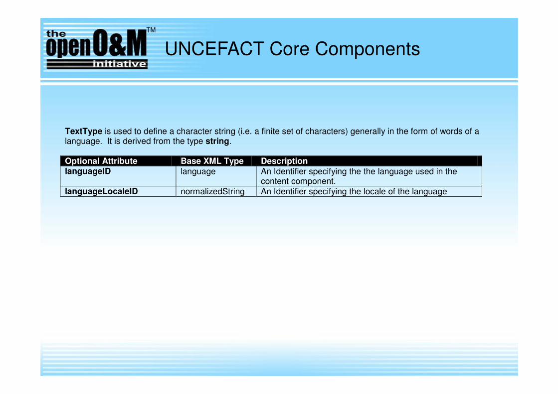
TextType is used to define a character string (i.e. a finite set of characters) generally in the form of words of a language. It is derived from the type string. Optional Attribute Base XML Type Description languageID language An Identifier specifying the the language used in the
content component. languageLocaleID normalizedString An Identifier specifying the locale of the language
UNCEFACT Core Components

Enabler: OpenO&M
Information Service Bus Model (ISBM)
Enabler: OpenO&M
Information Service Bus Model (ISBM)

Actual Proposed Design

Actual Proposed Design

Better Approach

Enabler: MIMOSA Open System Architecture for
Enterprise Application Integration (OSA-EAI) Common
Conceptual Object Model (CCOM) with Markup
Language (CCOM-ML)
Enabler: MIMOSA Open System Architecture for
Enterprise Application Integration (OSA-EAI) Common
Conceptual Object Model (CCOM) with Markup
Language (CCOM-ML)

MIMOSA Open Systems Architecture for
Enterprise Application Integration (OSA-EAI)
MIMOSA Open Systems Architecture for
Enterprise Application Integration (OSA-EAI)
The MIMOSA Open Object
Registry Is a Core O&M Interoperability Enabler for
Asset Intensive Industries.
•It provides a full mesh network for maintaining interrelationships between people, processes and systems in a Services Oriented Architecture.
•Unlike traditional Master Data Management (MDM), it is designed to support the highly dynamic requirements of physical asset management such as configuration management.
Enabler: OpenO&M – ISO 15926 Transform EngineEnabler: OpenO&M – ISO 15926 Transform Engine

OpenO&M – ISO 15926 Transform Engine
Aims and Benefits
• Automation of semantic integration
• Flexibility through open transformation
across ecosystems
• Standards-based transformation
• Reusable transformation through library
of mapping operators
• Transformation process for complex
transformations
• Extensibility allows dynamic changes
• End-user friendly tool guidance with
abstract visual notations for non-IT-experts58

59
Models on the Conceptual Level
ISO 15926 MIMOSA CCOM 3.2.3
*.rdf/*.qxf file *.xml file
Model
transformation
Model
transformation
Interface toInformation Bus
LIFTING TO ABSTRACT MODELS
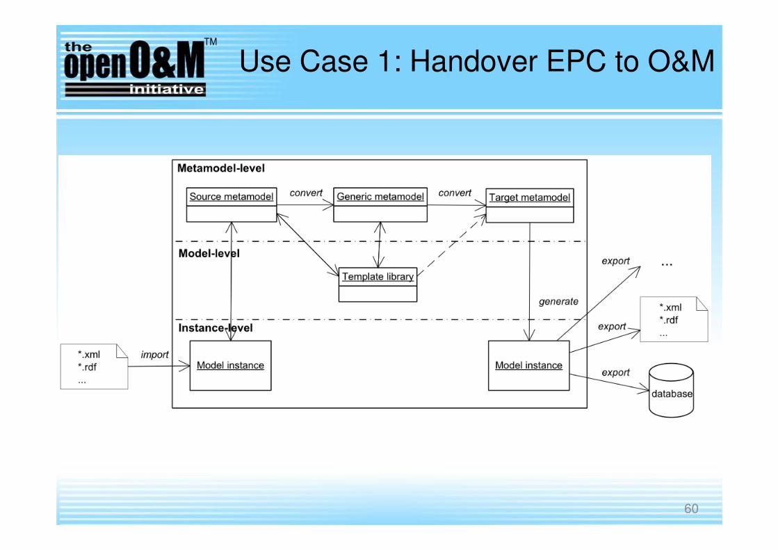
Use Case 1: Handover EPC to O&M
60

61
ISO 15926 Representation
• Templates in Reference Data Library (RDL): Specialized Templates from ISO 15927-7
• Templates defined inISO 15926-7
• Concepts defined inISO 15926-2
• Values
Use Case 1: Handover EPC to O&M

62
Export to open
standardfor example XSLT or QVT
Complex Transformation in Form of a Process
for example BPMN, EPC, BPELExport to open
standard
Use Case 1: Handover EPC to O&M

63
MIMOSA Representation
• Object Types in Topology
• Object Types from Asset Registry
• Instance Values
Use Case 1: Handover EPC to O&M

64
Use Case 1: Handover EPC to O&M