onesubsea subsea sampling system - upm forum · 3/7/2017 · subsea sampling module heated water...
TRANSCRIPT

22 – 23 February 2017 Houston, TX
Copyright 2017, Letton Hall Group. This paper was developed for the UPM Forum, 22 – 23 February 2017, Houston, Texas, U.S.A., and is subject to correction by the author(s). The contents of the paper may not necessarily reflect theviews of the UPM Forum sponsors or administrator. Reproduction, dis tribution, or storage of any part of this paper for commercial purposes without the written consent of the Letton Hall Group is prohibited. Non-commercialreproduction or distribution may be permitted, provided conspicuous acknowledgment of the UPM Forum and the author(s) is made. For more information, seewww.upmforum.com.
OneSubsea – Subsea Sampling System
Shailesh Rathod
Agenda
Representative Sampling
System Overview
Ongoing Projects
Q&A
Why Sample ?
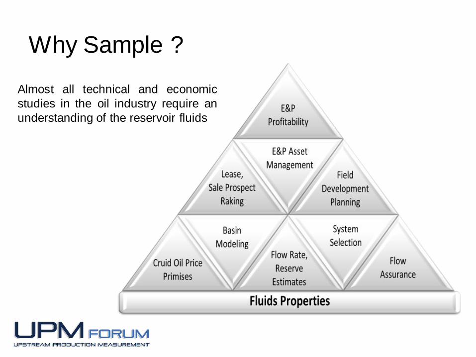
Almost all technical and economic
studies in the oil industry require an
understanding of the reservoir fluids
Multiphase Representative Sampling
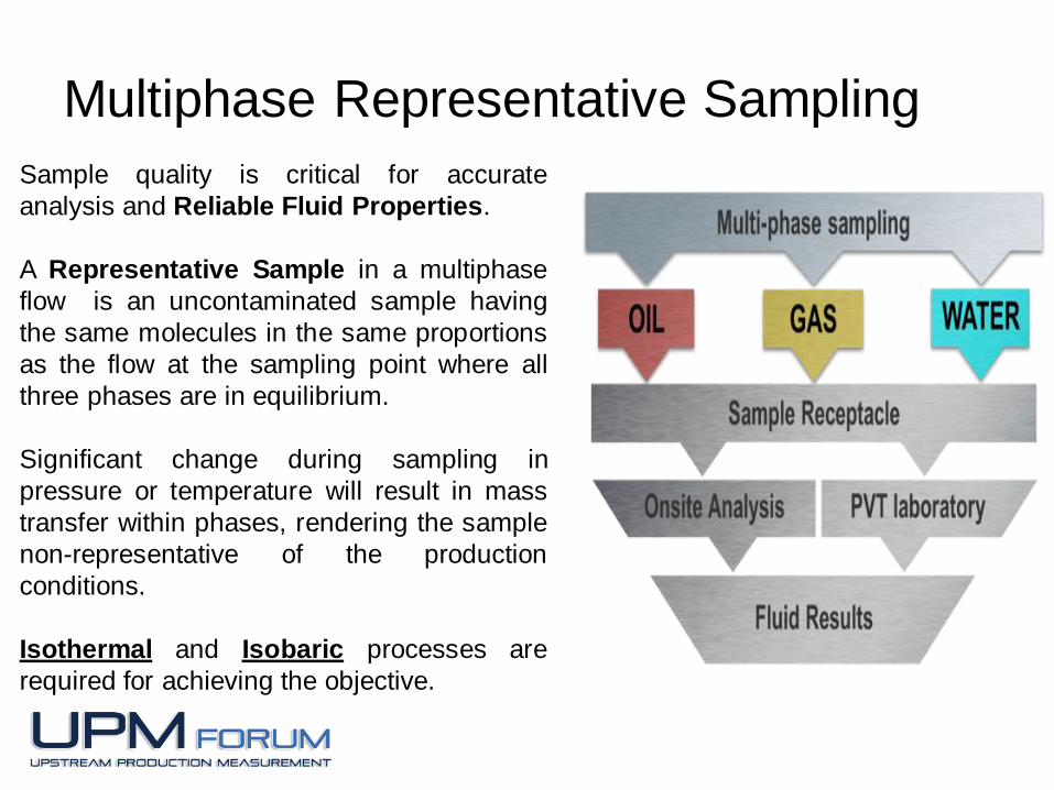
Sample quality is critical for accurate
analysis and Reliable Fluid Properties.
A Representative Sample in a multiphase
flow is an uncontaminated sample having
the same molecules in the same proportions
as the flow at the sampling point where all
three phases are in equilibrium.
Significant change during sampling in
pressure or temperature will result in mass
transfer within phases, rendering the sample
non-representative of the production
conditions.
Isothermal and Isobaric processes are
required for achieving the objective.
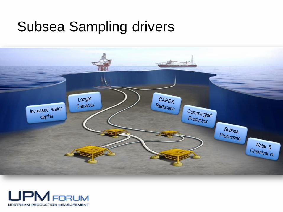
Subsea Sampling drivers
Subsea Sampling Applications
Production Monitoring
Reservoir Modeling and Management
Flow Assurance
Well Intervention
Subsea Processing
Enhanced Oil Recovery
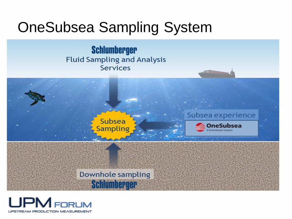
OneSubsea Sampling System
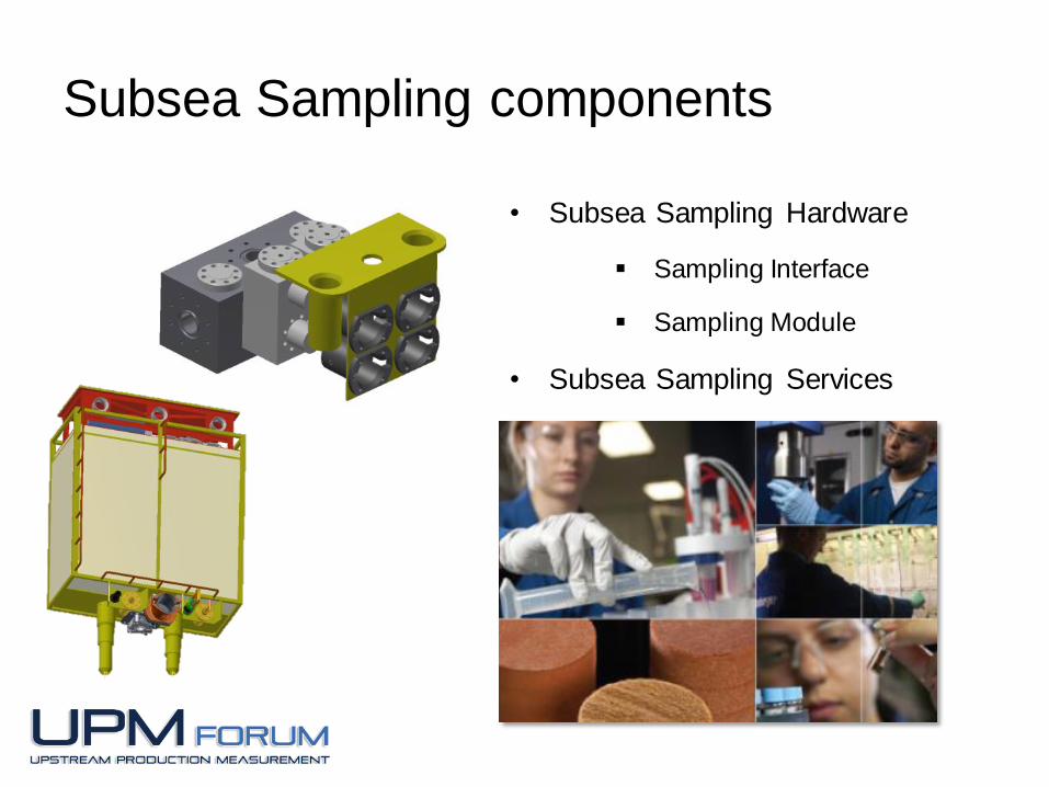
Subsea Sampling components
• Subsea Sampling Hardware
Sampling Interface
Sampling Module
• Subsea Sampling Services
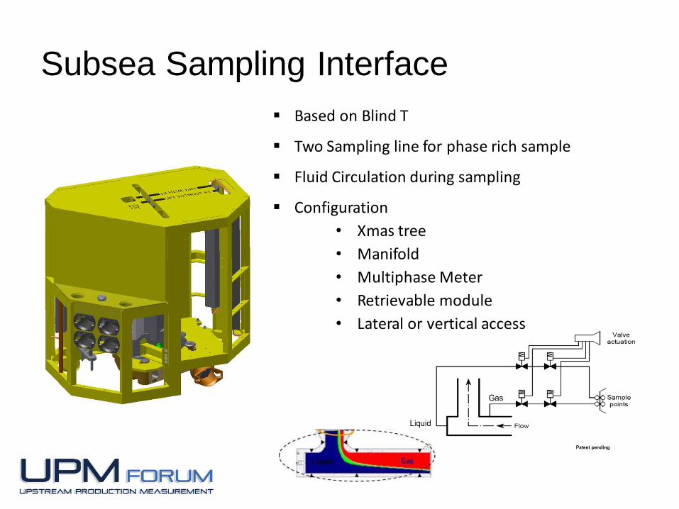
Subsea Sampling Interface
Based on Blind T
Two Sampling line for phase rich sample
Fluid Circulation during sampling
Configuration
• Xmas tree
• Manifold
• Multiphase Meter
• Retrievable module
• Lateral or vertical access
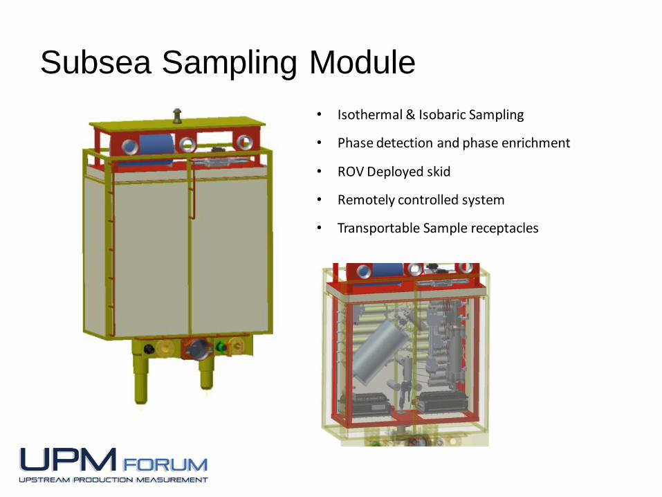
Subsea Sampling Module
• Isothermal & Isobaric Sampling
• Phase detection and phase enrichment
• ROV Deployed skid
• Remotely controlled system
• Transportable Sample receptacles
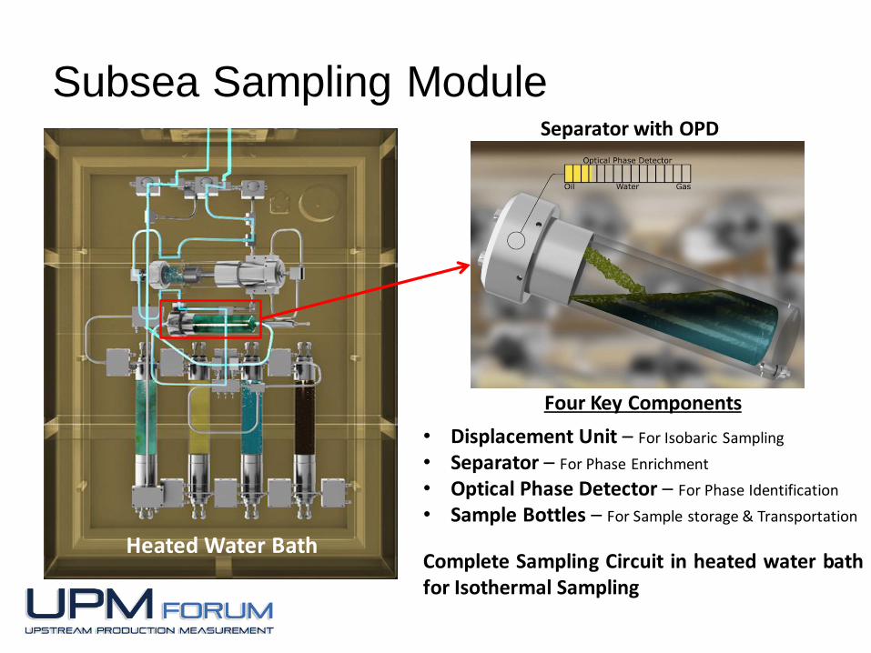
Separator with OPD
Subsea Sampling Module
Heated Water Bath
Four Key Components
• Displacement Unit – For Isobaric Sampling
• Separator – For Phase Enrichment
• Optical Phase Detector – For Phase Identification
• Sample Bottles – For Sample storage & Transportation
Complete Sampling Circuit in heated water bathfor Isothermal Sampling
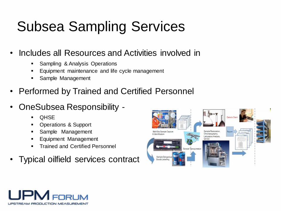
Subsea Sampling Services
• Includes all Resources and Activities involved in Sampling & Analysis Operations
Equipment maintenance and life cycle management
Sample Management
• Performed by Trained and Certified Personnel
• OneSubsea Responsibility - QHSE
Operations & Support
Sample Management
Equipment Management
Trained and Certified Personnel
• Typical oilfield services contract
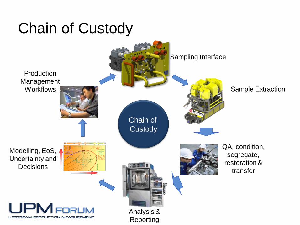
Chain of Custody
Sample Extraction
QA, condition,
segregate,
restoration &
transfer
Analysis &
Reporting
Modelling, EoS,
Uncertainty and
Decisions
Chain of
Custody
Sampling Interface
Production
Management
Workflows
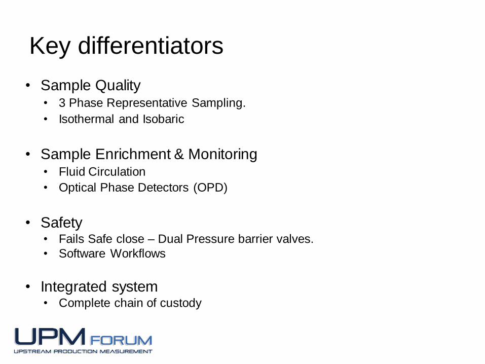
Key differentiators
• Sample Quality• 3 Phase Representative Sampling.
• Isothermal and Isobaric
• Sample Enrichment & Monitoring• Fluid Circulation
• Optical Phase Detectors (OPD)
• Safety• Fails Safe close – Dual Pressure barrier valves.
• Software Workflows
• Integrated system• Complete chain of custody
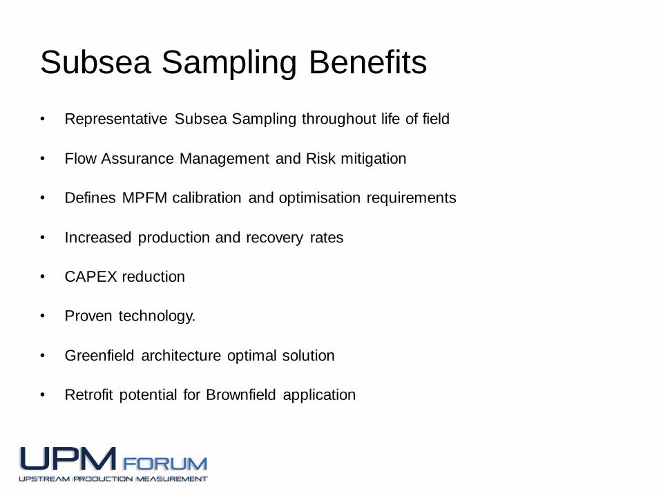
Subsea Sampling Benefits
• Representative Subsea Sampling throughout life of field
• Flow Assurance Management and Risk mitigation
• Defines MPFM calibration and optimisation requirements
• Increased production and recovery rates
• CAPEX reduction
• Proven technology.
• Greenfield architecture optimal solution
• Retrofit potential for Brownfield application
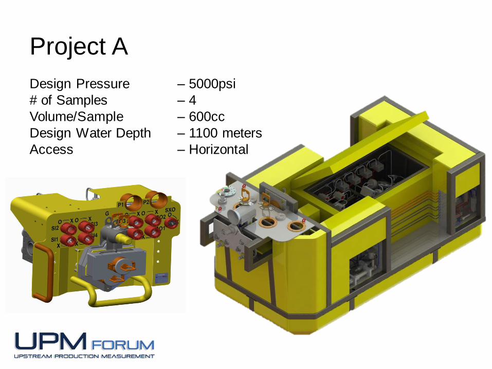
Project A
Design Pressure – 5000psi
# of Samples – 4
Volume/Sample – 600cc
Design Water Depth – 1100 meters
Access – Horizontal

Project A
Sampling Interface
Qualification and FAT completed to 10,000 psi and 121°C (standard SPS rating)
4 units delivered
Sampling Module Critical internal components qualified to 5000 psi and 121°C
Prototype flow loop test completed successfully
EFAT and SIT completed – May 2015
Delivery – Dec 2015

System Testing
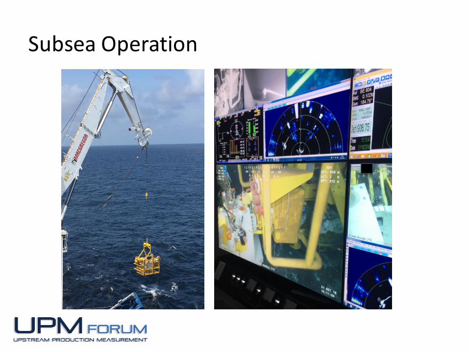
Subsea Operation
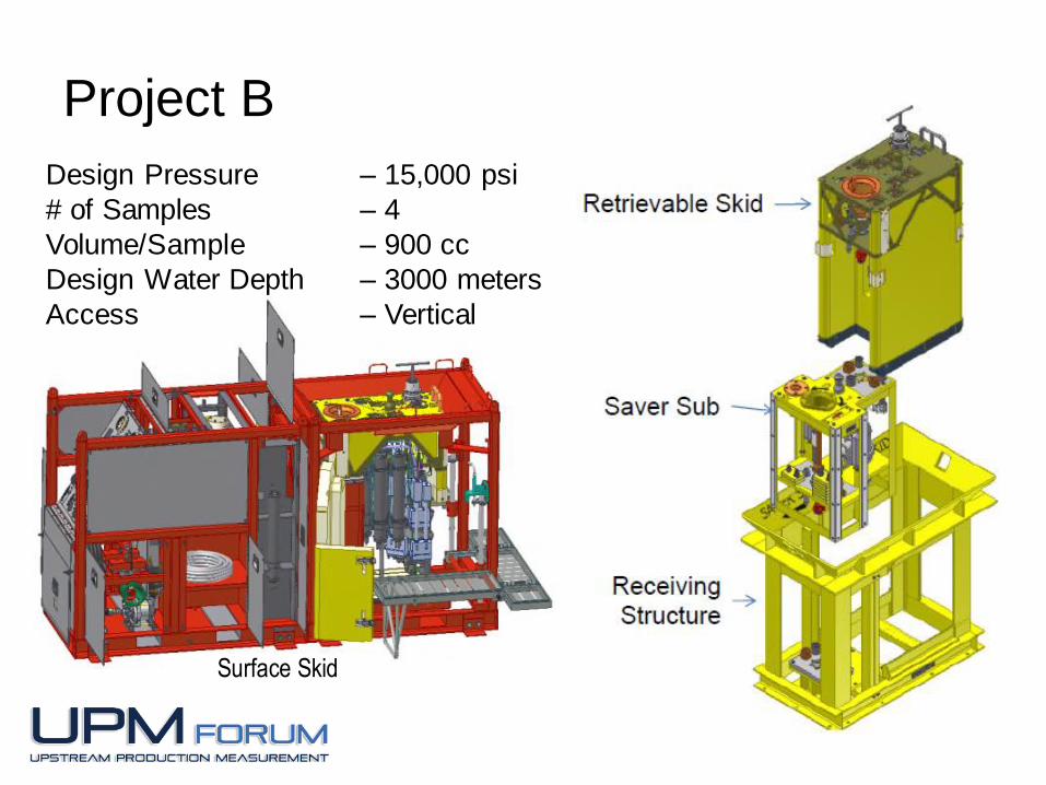
Project B
Design Pressure – 15,000 psi
# of Samples – 4
Volume/Sample – 900 cc
Design Water Depth – 3000 meters
Access – Vertical
Surface Skid

Project B
Receiving Structure - FAT completed
Impact Cover - FAT completed
Saver Sub - FAT completed
Long Term Cover - FAT completed
Debris Cover - FAT completed
Retrievable Skid - Initial testing completed
EFAT Completed - April 2015
Delivery - Dec 2015
Installed at
Subsea in
2013
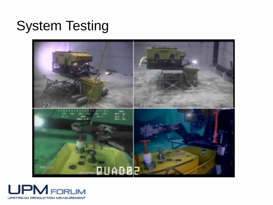
System Testing
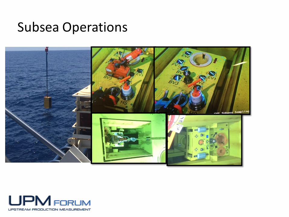
Subsea Operations
Thank You !!
Questions ??