one dimensional flow of blissful fluid -iii
DESCRIPTION
One Dimensional Flow of Blissful Fluid -III. P M V Subbarao Professor Mechanical Engineering Department I I T Delhi. Always Start with simplest Inventions……. Differential Form of Momentum Equation. One dimensional steady inviscid flow :. - PowerPoint PPT PresentationTRANSCRIPT
One Dimensional Flow of Blissful Fluid -III
P M V Subbarao Professor
Mechanical Engineering DepartmentI I T Delhi
Always Start with simplest Inventions……..

Differential Form of Momentum Equation
dpududx
dp
dx
duu 0
One dimensional steady inviscid flow :
dpudu
udp
du
1
The relation between pressure and velocity is continuous.
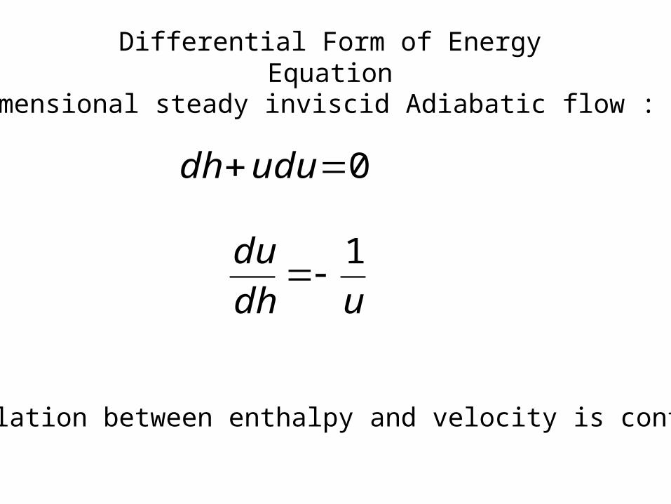
Differential Form of Energy Equation
One dimensional steady inviscid Adiabatic flow :
The relation between enthalpy and velocity is continuous.
0ududh
udh
du 1
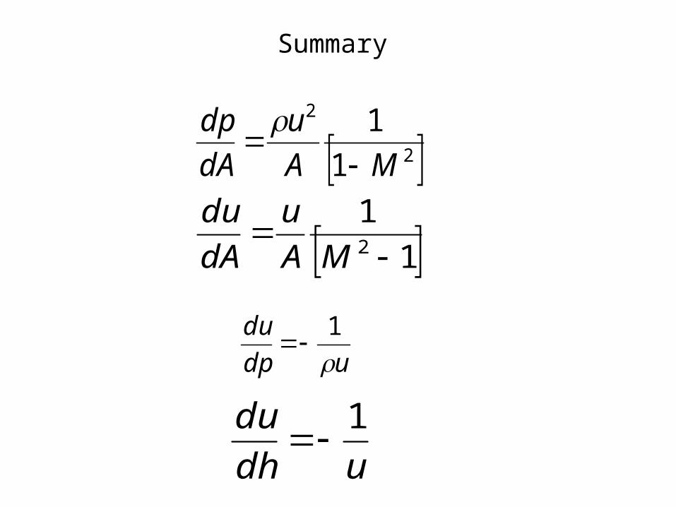
Summary
2
2
1
1
MA
u
dA
dp
1
12
MA
u
dA
du
udp
du
1
udh
du 1

p
dp
u
duM
12
p
dp
A
dA
M
M
1
12
2
d
p
dp
d
A
dA
M
M
12
2
Subsonic Nozzle Subsonic Diffuser
dA < 0 & M <1
So, du > 0 & dp <0
dA > 0 & M <1
So, du < 0 & dp>0
A
dA
Mu
du
1
12
T
dT
A
dA
M
M
1
12
2
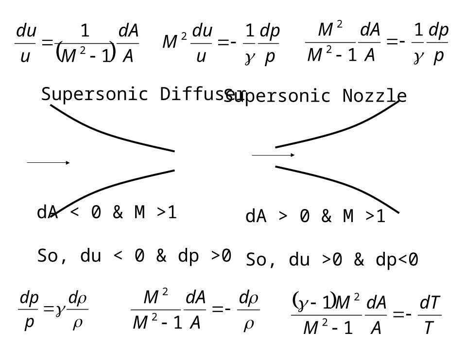
Supersonic Diffuser Supersonic Nozzle
dA < 0 & M >1
So, du < 0 & dp >0
dA > 0 & M >1
So, du >0 & dp<0
p
dp
u
duM
12
p
dp
A
dA
M
M
1
12
2
A
dA
Mu
du
1
12
d
p
dp
d
A
dA
M
M
12
2 T
dT
A
dA
M
M
1
12
2
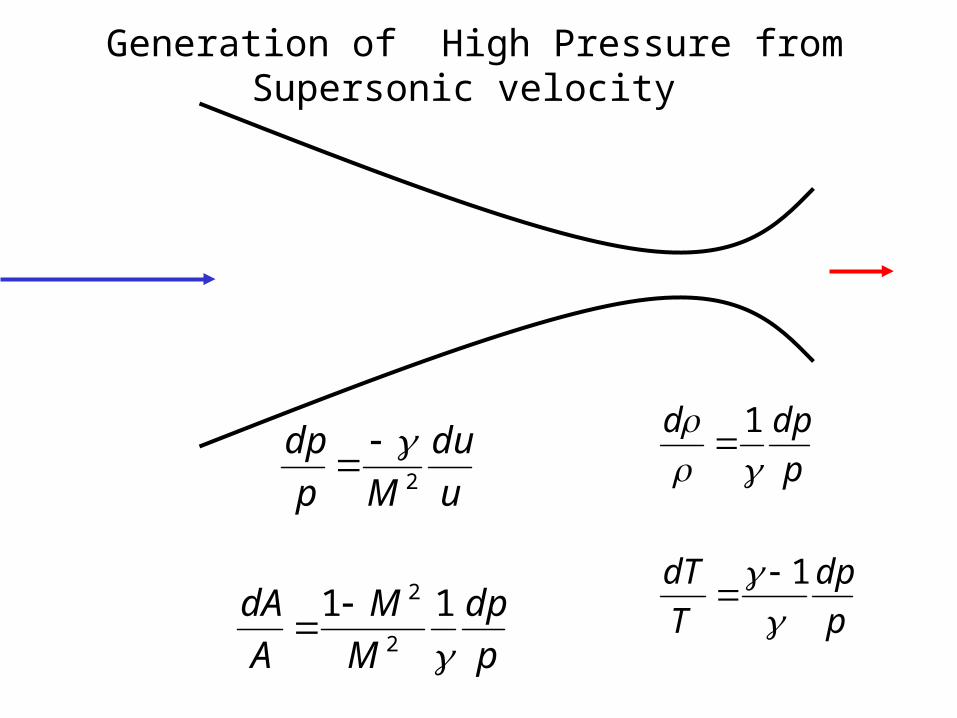
Generation of High Pressure from Supersonic velocity
u
du
Mp
dp2
p
dp
M
M
A
dA
11
2
2
p
dpd
1
p
dp
T
dT
1
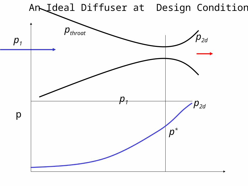
An Ideal Diffuser at Design Conditions
p1p2d
pthroat
p
p1
p*
p2d

Generation of Supersonic Velocity from Rest
p
dpM
u
du
2
p
dp
M
M
A
dA
11
2
2
p
dpd
1
p
dp
T
dT
1

RAMJET Engine

Capacity of A Cross Section : An implicit Model
Mass flow rate through any cross section of area A
)()()( xuxAxm
With a condition that sonic velocity occurs at throat !
thoratthroatthroat CAm
throatthroat
throatthorat RT
pC
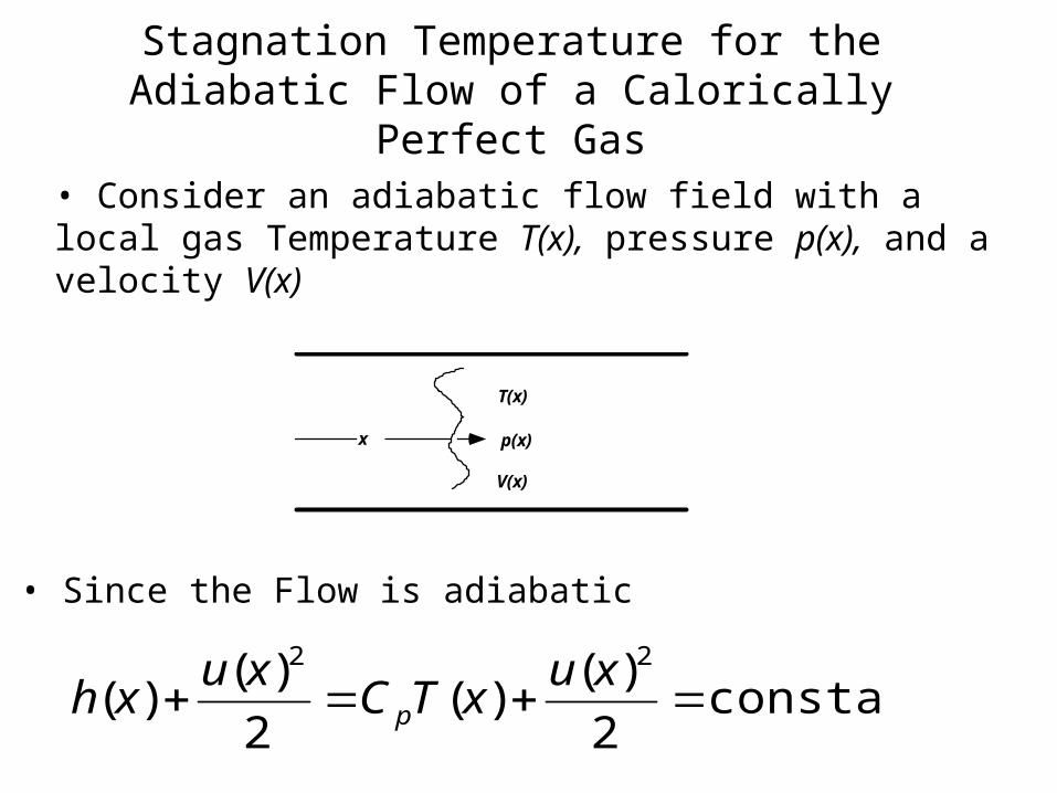
Stagnation Temperature for theAdiabatic Flow of a Calorically Perfect Gas
• Consider an adiabatic flow field with a local gas Temperature T(x), pressure p(x), and a velocity V(x)
x
T(x)
V(x)
p(x)
• Since the Flow is adiabatic
constant2
)()(
2
)()(
22
xu
xTCxu
xh p
y
To(y)
V(y)=0
po(y)
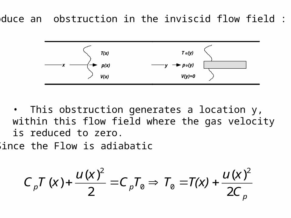
Introduce an obstruction in the inviscid flow field :
• This obstruction generates a location y, within this flow field where the gas velocity is reduced to zero.
• Since the Flow is adiabatic
ppp C
xuT(x)TTC
xuxTC
2
)(
2
)()(
2
00
2
x
T(x)
V(x)
p(x)
12
)()(
2
0
R
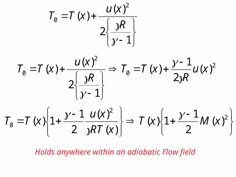
xuxTT
20
2
0 )(2
1)(
12
)()( xu
RxTT
R
xuxTT
22
0 )(2
11)(
)(
)(
2
11)( xMxT
xRT
xuxTT
Holds anywhere within an adiabatic Flow field
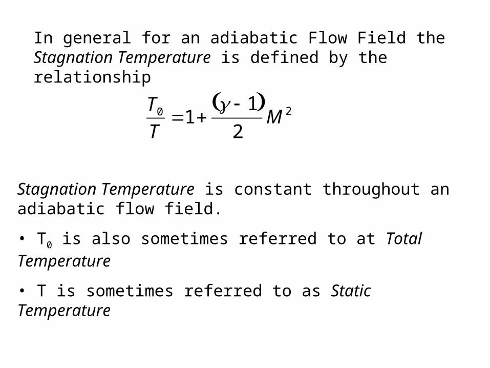
In general for an adiabatic Flow Field the Stagnation Temperature is defined by the relationship
T0
T1
1 2
M 2
Stagnation Temperature is constant throughout an adiabatic flow field.
• T0 is also sometimes referred to at Total Temperature
• T is sometimes referred to as Static Temperature
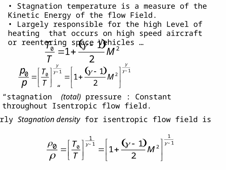
• Stagnation temperature is a measure of the Kinetic Energy of the flow Field.• Largely responsible for the high Level of heating that occurs on high speed aircraft or reentering space Vehicles …
T0
T1
1 2
M 2
p0
p
T0
T
1
1 1
2M 2
1
“stagnation” (total) pressure : Constant throughout Isentropic flow field.
• Similarly Stagnation density for isentropic flow field is
0
T0
T
1
1 1
2M 2
1
11
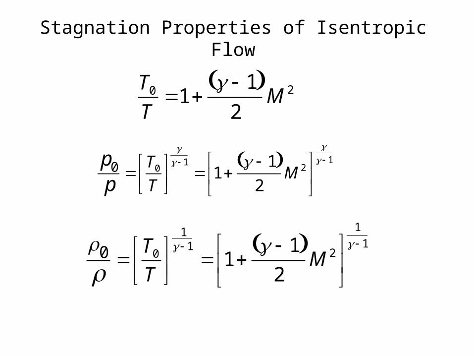
Stagnation Properties of Isentropic Flow
T0
T1
1 2
M 2
p0
p
T0
T
1
1 1
2M 2
1
0
T0
T
1
1 1
2M 2
1
11

What was Stagnation Temperature At Columbia Breakup
Loss Of Signal at:61.2 km altitude~18.0 Mach Number
T∞ ~ 243 K
T0
T1
1 2
M 2
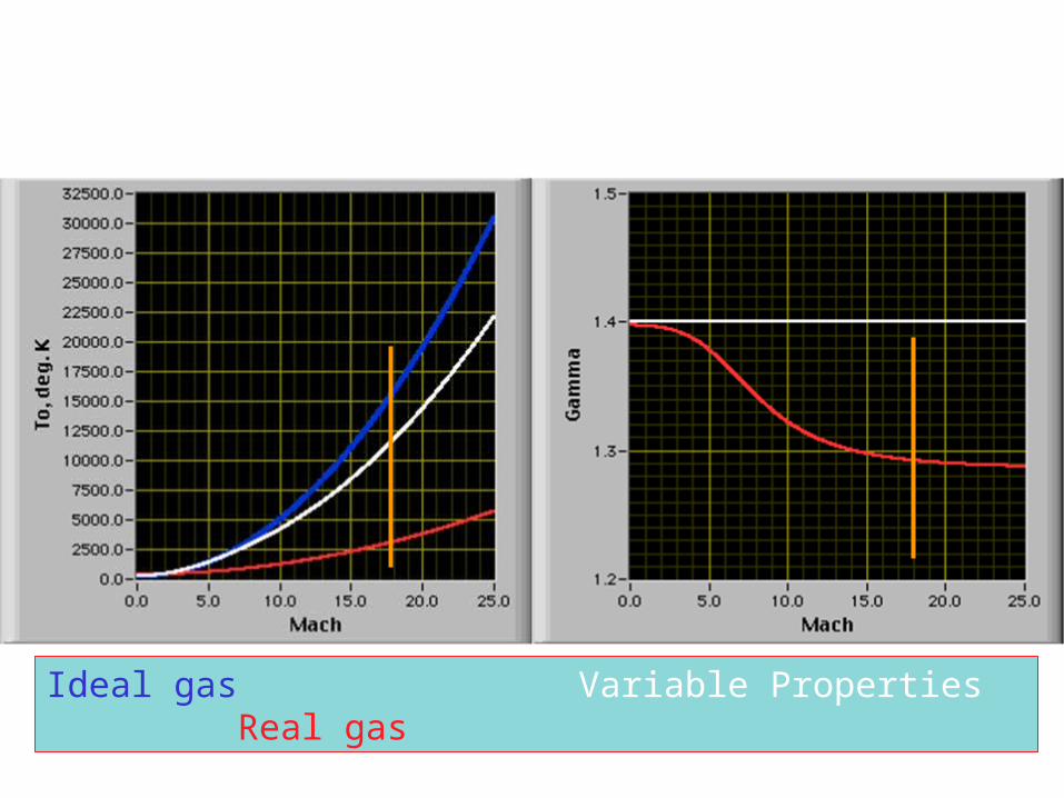
Ideal gas Variable Properties Real gas

Capacity of A Cross Section
Mass flow rate through any cross section of area A
)()()( xuxAxm
With a condition that sonic velocity occurs at throat !
thoratthroatthoat CAm
thoatthorat
thoatthorat RT
pC
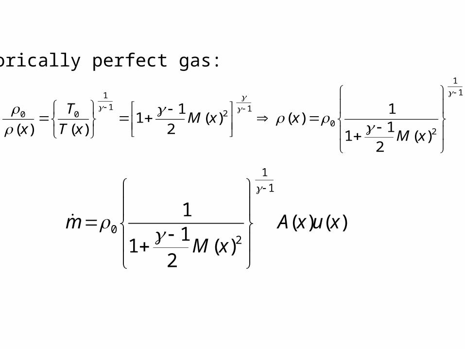
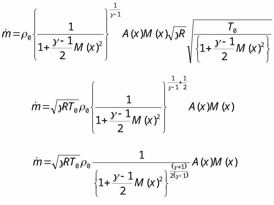
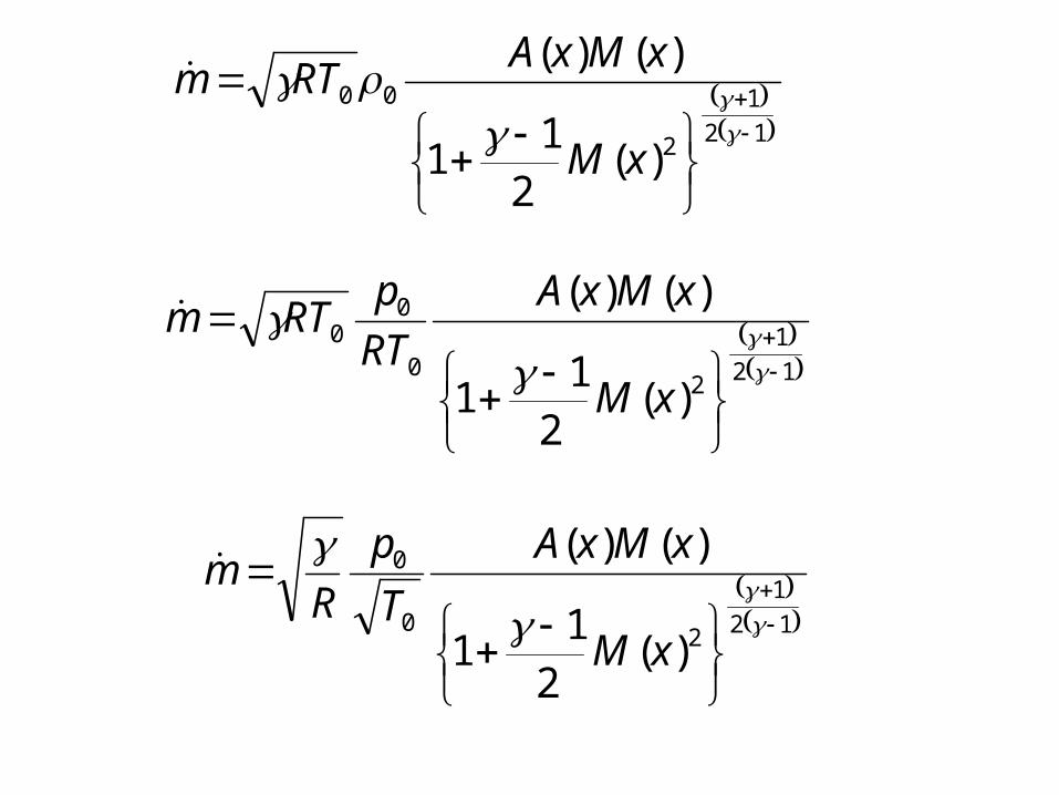
Calorically perfect gas:
1
1
20
12
1
1
00
)(2
11
1)()(
2
11
)()(
xMxxM
xT
T
x
)()()(
21
1
11
1
20 xuxA
xMm

T0
T1
1 2
M 2
2
0
)(2
11
)(xM
TxT
)()()()(
21
1
11
1
20 xcxMxA
xMm
RTxMxAxM
m
)()()(
21
1
11
1
20
2
0
1
1
20
)(2
11
)()()(
21
1
1
xM
TRxMxA
xMm
)()()(
21
1
12
1
1
1
200 xMxA
xMRTm
)()(
)(2
11
1
12
1
2
00 xMxA
xM
RTm
12
1
2
00
)(2
11
)()(
xM
xMxARTm
12
1
20
00
)(2
11
)()(
xM
xMxA
RT
pRTm
12
1
20
0
)(2
11
)()(
xM
xMxA
T
p
Rm
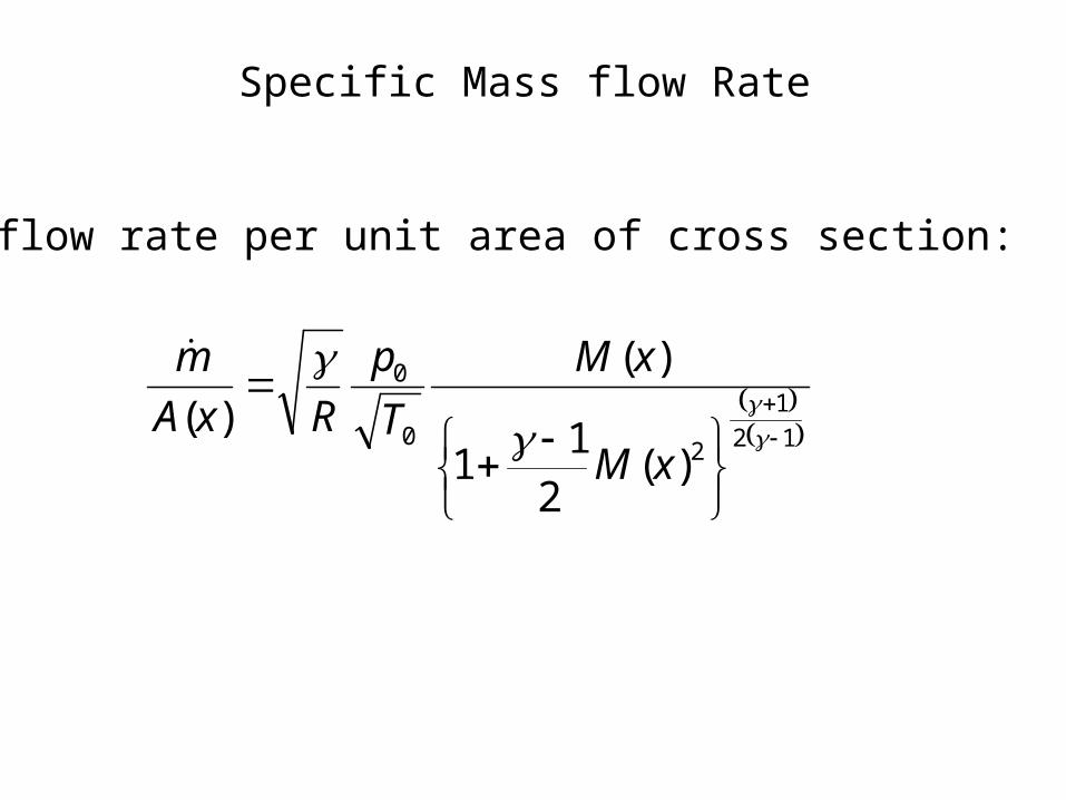
Specific Mass flow Rate
Mass flow rate per unit area of cross section:
12
1
20
0
)(2
11
)(
)(
xM
xM
T
p
RxA
m
Design of Converging Diverging Nozzles
P M V SubbaraoAssociate Professor
Mechanical Engineering DepartmentI I T Delhi
From the Beginning to the Peak or Vice Versa….

Quasi-One-Dimensional Flow

Distinction Between True 1-D Flow and Quasi 1-D Flow
• In “true” 1-D flow Cross sectional area is strictly constant• In quasi-1-D flow, cross section varies as a Function of the longitudinal coordinate, x• Flow Properties are assumedconstant across any cross-section• Analytical simplification very useful for evaluating Flow properties in Nozzles, tubes, ducts, and diffusersWhere the cross sectional area is large when compared to length

Specific Mass flow Rate
Mass flow rate per unit area of cross section:
12
1
20
0
)(2
11
)(
)(
xM
xM
T
p
RxA
m
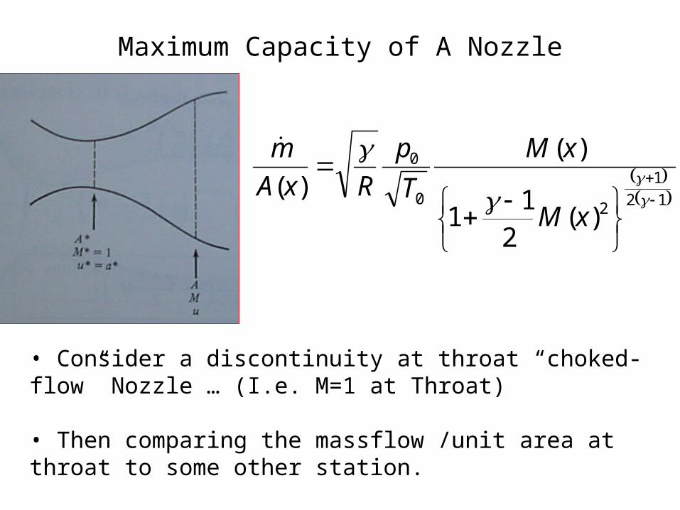
Maximum Capacity of A Nozzle
12
1
20
0
)(2
11
)(
)(
xM
xM
T
p
RxA
m
• Consider a discontinuity at throat “choked-flow” Nozzle … (I.e. M=1 at Throat)
• Then comparing the massflow /unit area at throat to some other station.
12
1
20
0
)(2
11
)(
)(
xM
xM
T
p
RxA
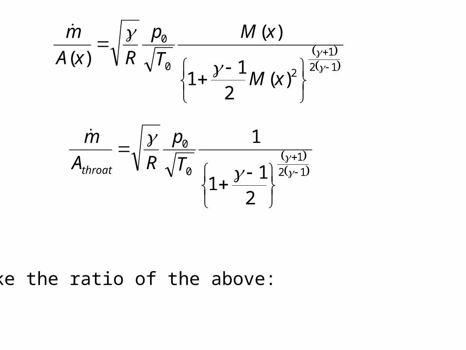
m
12
10
0
21
1
1
T
p
RA
m
throat
Take the ratio of the above:

12
10
0
12
1
20
0
21
1
1
)(2
11
)(
)(
T
p
R
xM
xM
T
p
R
xA
Athroat
12
1
12
1
2
21
1
1
)(2
11
)(
)(
xM
xM
xA
Athroat
12
1
2
12
1
)(2
11
21
)()(
xM
xMxA
Athroat
12
1
2)(2
11
1
2
)(
1)(
xMxMA
xA
throat
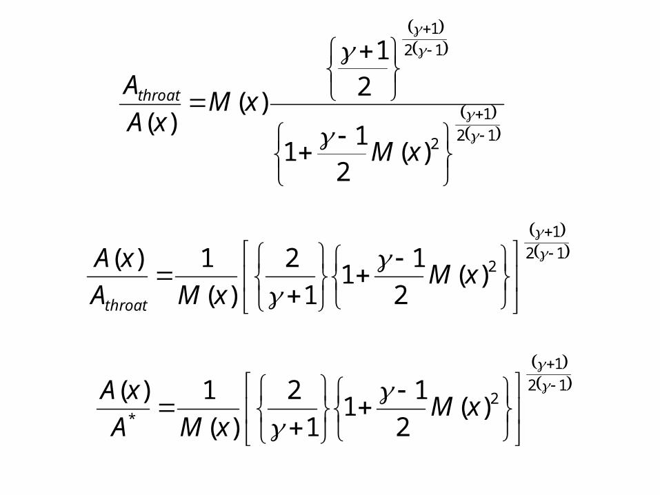
12
1
2*
)(2
11
1
2
)(
1)(
xMxMA
xA
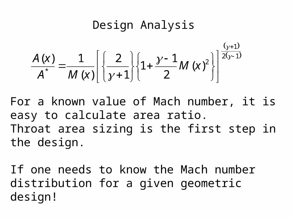
Design Analysis
12
1
2*
)(2
11
1
2
)(
1)(
xMxMA
xA
For a known value of Mach number, it is easy to calculate area ratio. Throat area sizing is the first step in the design.
If one needs to know the Mach number distribution for a given geometric design!
Find the roots of the non-linear equation.
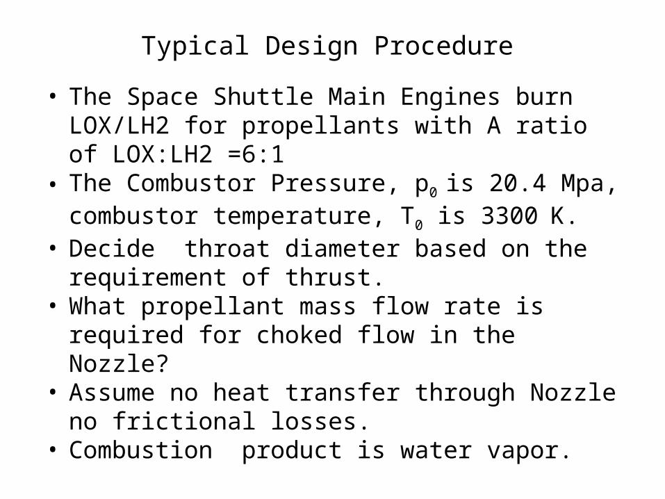
Typical Design Procedure
• The Space Shuttle Main Engines burn LOX/LH2 for propellants with A ratio of LOX:LH2 =6:1
• The Combustor Pressure, p0 is 20.4 Mpa, combustor temperature, T0 is 3300K.
• Decide throat diameter based on the requirement of thrust.
• What propellant mass flow rate is required for choked flow in the Nozzle?
• Assume no heat transfer through Nozzle no frictional losses.
• Combustion product is water vapor.
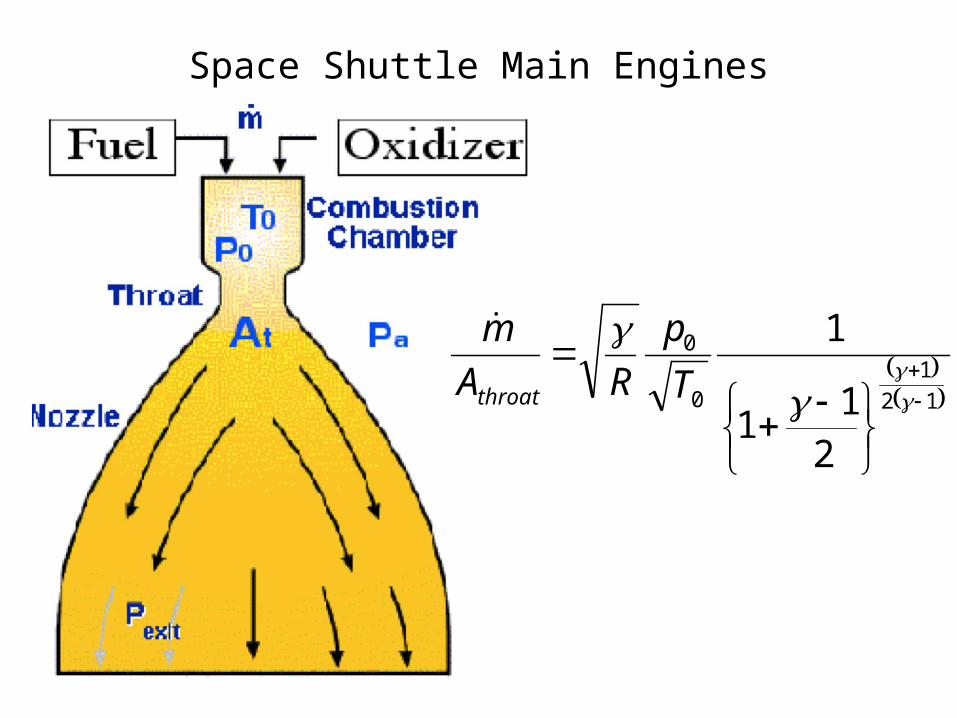
Space Shuttle Main Engines
12
10
0
21
1
1
T
p
RA
m
throat
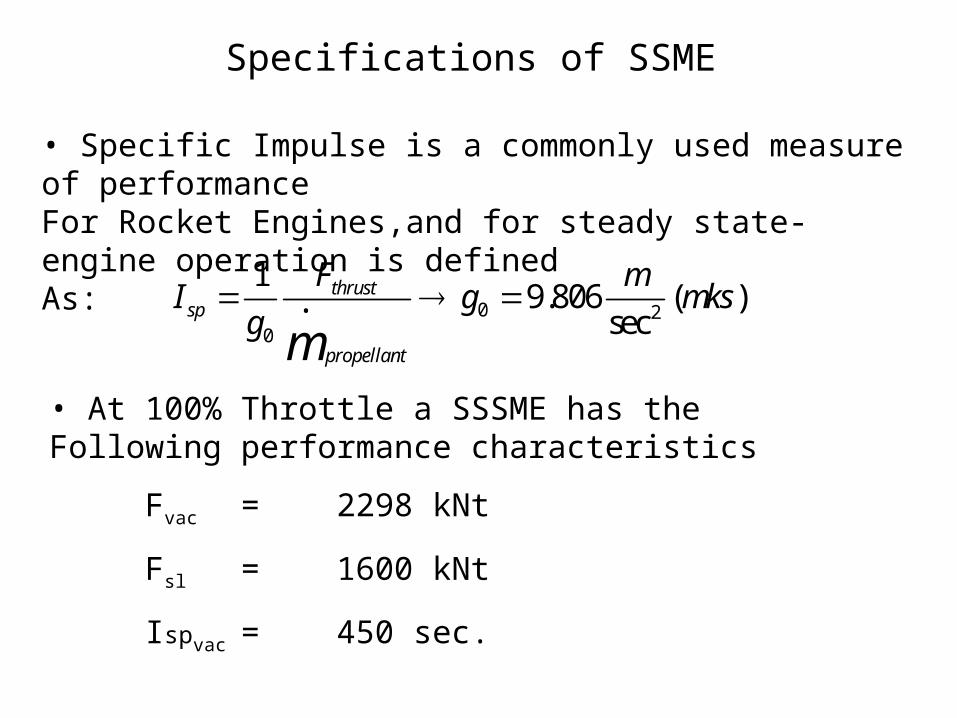
Specifications of SSME
• Specific Impulse is a commonly used measure of performanceFor Rocket Engines,and for steady state-engine operation is definedAs:
I sp 1
g0
Fthrust•
m propellant
g0 9.806m
sec2(mks)
• At 100% Throttle a SSSME has the Following performance characteristics
Fvac = 2298 kNt
Fsl = 1600 kNt
Ispvac = 450 sec.
SEA Level Performance
One needs to know the Mach number distribution for a given geometric design!
Find the roots of the non-linear equation.
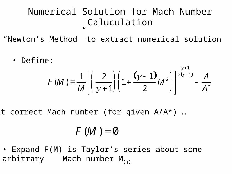
Numerical Solution for Mach Number Caluculation
• Use “Newton’s Method” to extract numerical solution
• At correct Mach number (for given A/A*) …
F(M ) 0
F(M ) 1
M
2
1
1 1
2M 2
1
2 1
A
A*
• Define:
• Expand F(M) is Taylor’s series about some arbitrary Mach number M(j)

F(M ) F(M ( j ) ) F
M
( j )
M M ( j ) 2F
M 2
( j )
M M ( j ) 2
2 ...O M M ( j ) 3
• Solve for M
M M ( j )
F(M ) F(M ( j ) )
2F
M 2
( j )
M M ( j ) 2
2 ...O M M ( j ) 3
F
M
( j )
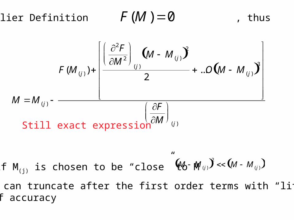
• From Earlier Definition , thusF(M ) 0
M M ( j )
F(M ( j ) )
2F
M 2
( j )
M M ( j ) 2
2 ...O M M ( j ) 3
F
M
( j )
• if M(j) is chosen to be “close” to M M M ( j ) 2 M M ( j )
And we can truncate after the first order terms with “little”Loss of accuracy
Still exact expression

• First Order approximation of solution for M
• However; one would anticipate that
“Hat” indicates that solution is no longer exact
M^
M ( j ) F(M ( j ) )
F
M
( j )
M M^
M M ( j )
“estimate is closer than original guess”
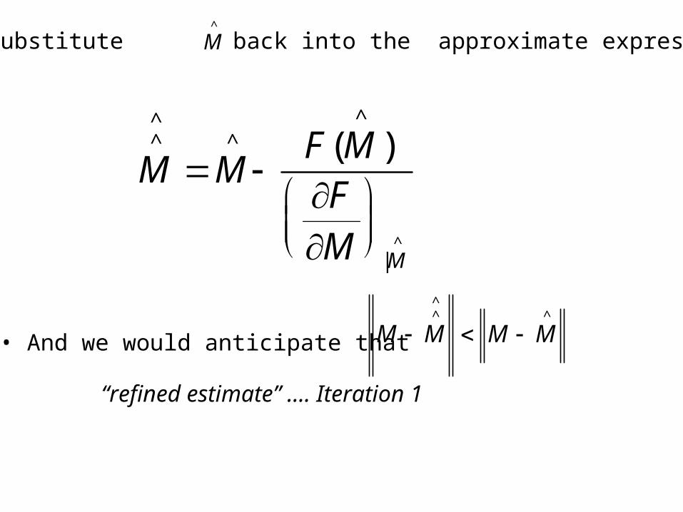
• And we would anticipate that
“refined estimate” …. Iteration 1
M^^
M^
F(M
^
)F
M
|M^
M M^^
M M^
• If we substitute back into the approximate expressionM^

• Abstracting to a “jth” iteration
Iterate until convergencej={0,1,….}
M^
( j1) M^
( j ) F(M
^
( j ) )F
M
|( j )
1
M^
( j1)
2
1
1 1
2M
^
( j1)
2
1
2 1
A
A*
A
A*
• Drop from loop when

Plot Flow Properties Along Nozzle Length
• A/A*
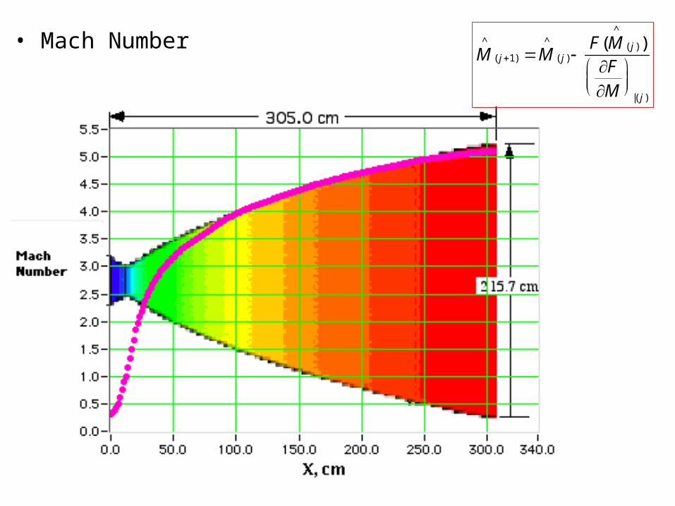
• Mach NumberM
^
( j1) M^
( j ) F(M
^
( j ) )F
M
|( j )

• Temperature T (x) T0
1 1
2M (x)2
T0 = 3300KTthroat = 2933.3 K

• Pressure
P0 = 20.4Mpa Pthroat = 11.32 MPa
P(x) P0
1 1
2M (x)2
1
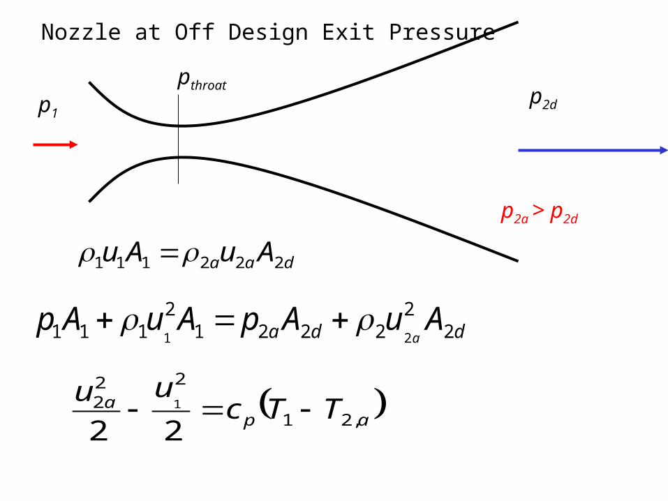
daa AuAu 222111
dda AuApAuApa 2
22221
2111 21
Nozzle at Off Design Exit Pressure
apa TTc
uu,21
222
221
p1p2d
p2a > p2d
pthroat

Nozzle at Off Design Exit Pressure
p1
p1 > p2a > pthroat
pthroat
p
p1 p2a
p*
P*2a
p2d