on site generation of oxidants - suframa.gov.br · aqua access innovations in water technology tm...
TRANSCRIPT

Aqua Access
Innovations in Water Technology
TM
On Site Generationof
Oxidants
Rodney E. Herrington
www.aquaaccess.com
(505) 362-0575

OSG Is Completely Benign
Salt
+ +
Water Electricity Liquid
Chlorine

TMAqua Access
Innovations in Water Technology
Aqua Access
Innovations in Water Technology
Water Salt
On Site Generator
Oxidant
Storage
Tank
ApplicationChlorine Solution

K1 and K2
Ease of Operation – Fully automated operation. Simple display with indicator lights for all functions. No pumping or clogging
Residual Disinfectant – prevents recontamination of water by maintaining a chlorine residual while providing enhanced oxidation with mixed oxidants
Economic Model – For village, community or light industrial applications. Capacities of 1 or 2 kilograms of chlorine production per day. Can be produced locally at low cost using rotationally molded low density polyethylene
Treatment Capacity – Produces a strong chlorine disinfection solution in a continuous batch operation. Runs until the bottom solution tank is full and then goes to standby until the tank level drops
Power – 110/220 VAC single phase power
Long-Term Functionality – No consumables to replace. No parts to replace. 10 year shelf life
Convenient Size – 26” Dia x 42” High. Convenient height for loading a bag of salt in the upper salt tank
Sustainable – only consumable is common salt and electricity
Reduces Chlorine Taste – mixed oxidants have less chlorine taste than chlorine gas of sodium hypochlorite

TMAqua Access
Innovations in Water Technology
•Can be configured for either 3, 5, 7, or 11 kilograms per day
of free available chlorine production
• Stainless steel passivated enclosures to operate in any
industrial environment.
• Includes separate power supply and fluid controls cabinets.
• External heat exchanger cools the control cabinet.
• Feed water temperature is maintained above 10⁰C by an
integral resistance heater thereby allowing feed water
temperatures as low as 1C.
• Requires a water softener, brine generator tank, an oxidant
storage tank, and a mode of injection.
K Series
Capacity 3, 5, 7, or 11 kg/day FAC
Power208 VAC, 1 ph, 50/60 hz,
30A
FAC Concentration 4,500 mg/L
Flow Rate 25 to 91 LPH
Feed Water Temp >1⁰C < 30⁰C
Feed Water Pressure 3 bar minimum
Dimensions0.7m W x 1.8m T x 0.25m
D
Weight 140 kg
K Series

TMAqua Access
Innovations in Water Technology
• Can be configured for either 22, 33, or 44 kilograms per day
of free available chlorine production
• Stainless steel passivated enclosures to operate in any
industrial environment.
• Includes separate power supply and fluid controls cabinets.
• Heat exchanger cools the control cabinet.
• Feed water temperature is maintained above 10⁰C by an
integral resistance heater thereby allowing feed water
temperatures as low as 1C.
• Requires a water softener, brine generator tank, an oxidant
storage tank, and a mode of oxidant injection.
K22-33-44
K22 K33 K44
Capacity 22 kg/day FAC 33 kg/day FAC 44 kg/day FAC
Power
2 circuits at
440 VAC, 3 ph, 50/60
hz, 25A
OR
208 VAC, 3ph,
50/60 hz, 50A
3 circuits at
440 VAC, 3 ph,
50/60 hz, 25A
OR
208 VAC, 3ph,
50/60 hz, 50A
4 circuits at
440 VAC, 3 ph,
50/60 hz, 25A
OR
208 VAC, 3ph,
50/60 hz, 50A
FAC Concentration 5,000 mg/L
Flow Rate 204 LPH 306 LPH 408 LPH
Feed Water Temp >1⁰C < 30⁰C
Feed Water Pressure 4 bar minimum
Dimensions 1.2m W x 1.5m H x 0.7m D
Weight 650 kg 680 kg 710 kg

Aqua Access
Innovations in Water Technology
TM
MIXED OXIDANTSVS
ON-SITE HYPOCHLORITE

TMAqua Access
Innovations in Water Technology
The higher the energy applied, the stronger the oxidant produced
Oxidation Potential Correlates with Energy
Oxidation Potential of Various
Chemistry Products
Re
lati
ve
Ox
ida
tio
n P
ote
nti
al
Flu
ori
ne
Hyd
roxyl
rad
ical
Ato
mic
Oxyg
en
Ozo
ne
Hyd
rog
en
Pero
xid
e
Perh
yd
roxyl
Rad
ical
Perm
an
gan
ate
Ch
lori
ne D
ioxid
e
Hyp
oid
ou
s A
cid
Ch
lori
ne
Bro
min
e
Iod
ine
MIXED OXIDANTS
SODIUM HYPO

TMAqua Access
Innovations in Water Technology
• Effective against a wider range of organisms
• Highly effective against biofilm
• Several orders of magnitude (logarithmic) higher inactivation
• Faster kill rate
• Reduced CT values (Contact x Time)
Studies Show Mixed Oxidants Have Better Disinfection Efficacy
Aqua Access knows how to optimize OSG design for mixed oxidants or on-site hypo

TMAqua Access
Innovations in Water Technology
Mixed Oxidants Are Stronger than On-Site Hypo, which is Stronger than Bulk Hypo
Mixed
Oxidants
On-Site
HypoBulk
Hypo
Energ
y A
pplie
d
Increased Disinfection Efficacy
Protozoa
Bacteria
Virus

Aqua Access
Innovations in Water Technology
TM
COST

TMAqua Access
Innovations in Water Technology
Chemical raw materials costs are rising,while OSG feedstocks are more stable
Producer Price Index, U.S. Department of Labor, Bureau of Labor Statistics
Bulk hypo estimated from chlorine and caustic soda prices (excludes transportation costs);
Chlorine gas compressed or liquefied; Salt evaporated or solar; and Electric power

TMAqua Access
Innovations in Water Technology
• Higher upfront capital cost, but lower operating and maintenance costs
• ROI typically occurs in 1 to 3 years
• Costs associated with other processes are often reduced– Reduced pH adjustment chemicals
– Longer filter runs
– Reduced alum / polymer consumption
– Reduced sludge handling
– Reduced corrosion
OSG Cost Structure

TMAqua Access
Innovations in Water Technology
Delivery of Salt Is 4X More Efficient than Delivery of Bulk Hypo
Hypo Tanker Salt Tanker
Tanker Capacity 15,000 L (18,500 kg) 21,800 kg
Notes
1L of 12.5% hypo weighs 1.2 kg by mass, but only
generates 0.12 kg FAC
1.2 kg of salt generates ~0.4 kg FAC – the same mass of
salt offers 3.4X more capacity than hypo
FAC Capacity per kg Mass 0.100 kg FAC 0.333 kg FAC
FAC Capacity by Load 1,800 kg FAC 7,200 kg FAC
Style of Truck

TMAqua Access
Innovations in Water Technology
Transport requirements are reduced 75% with on-site hypo and 83% with mixed oxidants
OSG Reduces Transport, Logistics, and Fuel Requirements
(Assuming that bulk hypo and salt are transported the same distance)

Aqua Access
Innovations in Water Technology
TM
MAINTENANCE

TMAqua Access
Innovations in Water Technology
• No dilution to maintain chlorine stability –disinfectant is < 1% FAC, and is generated on demand and used in 24 hours
• Logistics are minimized – OSG salt storage can be designed for long time periods
• OSG pH is near neutral, so acid addition is reduced or eliminated
• Corrosion is virtually eliminated since there is no off-gassing
• No scaling of pumps, backpressure devices, rotometers, or piping
Maintenance is Easier with OSG than with Bulk Hypo

TMAqua Access
Innovations in Water Technology
• Brine tank fill (manual vs. automatic) – occurs weekly to yearly, depending on size
• Water and brine filter changeout – monthly to quarterly, depending on water and salt quality– Takes 10 min. per changeout
• Acid-washing cell – quarterly to annually, depending on salt quality– Takes 30 min. per acid wash
– There is NO membrane in the cell, minimizing cell maintenance requirements
OSG Maintenance

Aqua Access
Innovations in Water Technology
TM
SAFETY

TMAqua Access
Innovations in Water Technology
• Biocides - bleach, sodium bromide, bromines, proprietary biocides, and various others
• OSG - uses only salt
OSG is Safer than Conventional Biocides
Biocides Salt
NFPA Safety Rating 2 or 3 0
Spills reportable Yes, often No
Pressurized lines Yes, often No
Storage issues Yes, often No

TMAqua Access
Innovations in Water Technology
• Cannot form chlorine gas if acid is accidentally added to hypo tank (due to rapid drop in pH)
• Accidents with bulk hypo are actually more prevalent than with chlorine gas
• 90% of hypo accidents are attributed to customer storage or process error
• Any safety risks with OSG are easily controlled – do not rely on operator intervention
OSG Is Safer Than Bulk Hypo
10
0 30
1vs.
OSG Bulk Hypo

TMAqua Access
Innovations in Water Technology
• Hydrogen Venting– All electrolytic processes generate hydrogen gas– Hydrogen is lighter than air and can be easily vented to
prevent concentration– Passive engineered vent systems maintain hydrogen at
<1% (the Lower Explosive Limit (LEL) is 4.1%)– Automated dilution blower systems available
• Electrical Safety– Small OSG systems are low voltage– Higher voltage systems use electrical interlocks– Maintenance can be performed without any risk of lethal
shock
OSG Safety

Aqua Access
Innovations in Water Technology
TM
ENVIRONMENTALLY FRIENDLY
TMAqua Access
Innovations in Water Technology
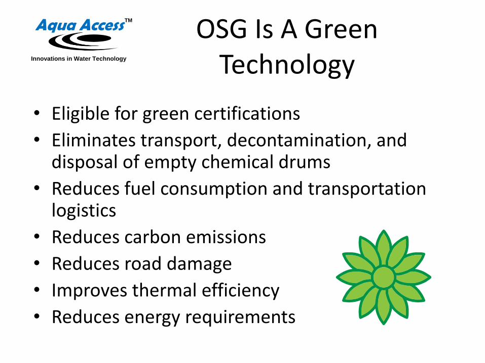
• Eligible for green certifications
• Eliminates transport, decontamination, and disposal of empty chemical drums
• Reduces fuel consumption and transportation logistics
• Reduces carbon emissions
• Reduces road damage
• Improves thermal efficiency
• Reduces energy requirements
OSG Is A Green Technology

TMAqua Access
Innovations in Water Technology
Reduced
DBPs
Micro-
flocculation
Biofilm
Control
Enhanced
Residual
Superior
Disinfection
Customer
Experiences
Reduced
Corrosion
Advantages of Mixed Oxidants
Improved
T&O
Extended
Filter Runs
Improved
Oxidation

TMAqua Access
Innovations in Water Technology
Dr. Linda Venczel, University of North Carolina
Superior Disinfection
Ref: Venczel Dissertation

TMAqua Access
Innovations in Water Technology
Inono Hot Springs, JapanBore Scope Camera Video Tape by NSP
Biofilm Elimination
Courtesy: NSP Corporation
Legionella resides
in biofilm - the
facility was not in
compliance with
health standards
In 6 days most
biofilm was removed.
Completely removed
in 22 days.

TMAqua Access
Innovations in Water Technology
Longer-Lasting Chlorine Residual in the Distribution
System
Can dose 30% less at the plant to achieve
the same chlorine residual in distribution
Can dose the same as with chlorine gas
or sodium hypo as before, but maintain a
higher chlorine residual in the
distribution system
Can maintain a chlorine residual value
much further out in distribution
Can maintain a chlorine residual value for
a much longer time in the distribution
system

TMAqua Access
Innovations in Water Technology
Q2 Q3Q4 Q1
0
20
40
60
80
100
120
140
Reduced Formation of TTHMs
Chlorine Gas
Mixed Oxidants
Chlorine Gas
(Q2 '05 - Q1 '06)
Mixed Oxidants
(Q2 '06 - Q1 '07)
Coto Laurel, Puerto Rico
Disinfection By-ProductsReduced by 35%
Ref: AWWA Journal

TMAqua Access
Innovations in Water Technology
• Iron (Fe)
• Manganese (Mn)
• Ammonia (NH3)
• Hydrogen Sulfide (H2S)
More Rapid Oxidation

TMAqua Access
Innovations in Water Technology
Mixed oxidants form only 18% of Pb levels and 69% of Cu levels in pipelines versus levels formed by sodium hypo
4 weeks exposure, 1 mg/L FAC Residual
Average Metal Concentration
0
0.1
0.2
0.3
0.4
0.5
0.6
Pb Formation Cu Formation
mg
/L Mixed Oxidant
Sodium Hypo
C&E Engineering Partners, Inc. Data from Westerly, RI, May 2006.
Corrosion Is Reduced

TMAqua Access
Innovations in Water Technology
Comparison of Chlorine Alternatives

Aqua Access
Innovations in Water Technology
TM
MIXED OXIDANT BENEFITS BY APPLICATION

TMAqua Access
Innovations in Water Technology
• Biofilm Control
• Much more durable chlorine residual – possible elimination of booster stations
• Reduced chlorine demand (30%)
• Reduced TTHM by-product formation (30%)
• Improved filter backwash cycle (100%)
Potable Water Benefits
Enhanced Oxidation◦ Reduced alum and polymer
consumption (40%)◦ Reduced sludge removal (20%)◦ Better tasting water
More Neutral pH◦ Reduction in lime / acid requirements (50%)◦ Reduced pipe corrosion (80% for lead, 30% for copper)

TMAqua Access
Innovations in Water Technology
• Wastewater– Reduced chlorine demand
– More stable dechlorination requirements
– Reductions in dechlorination chemicals
Wastewater / Water Reuse Benefits
Water Reuse◦ Biofilm control◦ Improved water quality for
irrigation, cooling water, or other reuse applications
◦ Chlorine residual required

TMAqua Access
Innovations in Water Technology
• No algae growth – easier to maintain
• Effective at a high pH
• Can reduce or eliminate acid requirements
Cooling Tower Benefits
More thorough disinfection
Biofilm removal◦ Maximizes thermal
efficiency
◦ Eliminates Legionella

TMAqua Access
Innovations in Water Technology
• Better bacterial control– No shocking required– Less maintenance – reduces algae and biofilm formation
• Reduced chlorine demand• Better water quality
– No itchy eyes– No burning skin– Improved water clarity
• Better air quality– Less chlorine odor– Potential to reduce asthma occurrences– Less corrosion of facility structures
• Neutral pH reduces need for adjustment chemicals
Aquatics Benefits

TMAqua Access
Innovations in Water Technology
Wastewater
Treatment
Cooling Tower
Water Treatment
Reclaimed
WaterMain Plant
Process Water
Clean in Place (CIP)
Bottle Washing
And Rinsing
OSG Food and Beverage Applications

TMAqua Access
Innovations in Water Technology
• Better microbial control
• Improved compliance
• Reduced risk of shutdown
– Reduced microbial-induced corrosion (MIC)
Beverage Processing Benefits
Reduction of CIP cycles◦ Increased time for production
◦ Reduced energy consumption (cleaning method is non-thermal)
◦ Cost savings
Can be used in each step of plant process◦ CIP, cooling towers, process water, wastewater

TMAqua Access
Innovations in Water Technology
Pre-rinse
Caustic Rinse SanitizerPost-rinse
Traditional Process: more steps mean less beverage production time
90 Minutes
50 Minutes
Mixed Oxidants Enhance Productivity via Reduced CIP Time
Mixed Oxidants: requires only 3 steps,
significantly increases beverage production time
RinseMixed
OxidantsRinse

TMAqua Access
Innovations in Water Technology
Individual Water Purifier
“Safe Water for the Price of Salt”

Markets
DEVELOPING WORLD:
1.2 billion people without safe water.
Half of the hospital beds in developing countries occupied by people with water-borne disease.
According to WHO 3.4 million people die each year from waterborne disease.
The WHO has proven that chlorine saves lives.
GOVERNMENT:
Disaster victims
Relief workers
Marines
Soldiers
RETAIL:
Hikers, campers, and outdoorsmen want the best technology for “found” water sources.
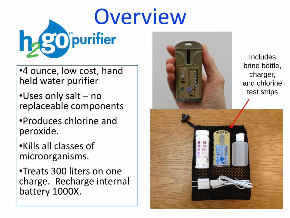
Overview
•4 ounce, low cost, hand held water purifier
•Uses only salt – no replaceable components
•Produces chlorine and peroxide.
•Kills all classes of microorganisms.
•Treats 300 liters on one charge. Recharge internal battery 1000X.
Includes
brine bottle,
charger,
and chlorine
test strips

Solution
+Free Everywhere
=

An Innovative
Reverse Osmosis
Membrane Technology

A Multi-billion Industry and Growing
RO Hand PumpUnder Counter System
Large Commercial Seawater Systems

Hypothesis: Water Filtration Membrane Elements Can Be Significantly Improved with Embossed or
Printed Feed Spacers
Innovative Thin Feed Spacer
Designs can be spaced much
closer together (more surface
area in the same size element)
and fouling potential is
significantly reduced
Patented and patents pending
Conventional membrane elements
use a mesh material to space
membranes apart, but traps particles
and creates biofouling – the leading
cause of membrane failure and plant
maintenance

Spiral Wound Element Design with Embossed or Printed Spacer
Patented and patents pending

Potential Advantages of Innovations Shown in this Presentation
• Up to twice as much permeate flow in the same housing size
• Scale Control
• Reduced fouling from biofilm and higher micron pre-filtration requirements
• Higher recovery to reduce reject flow
• Simplify under counter or industrial systems by increasing permeate flow sufficient to eliminate the pressure vessel

A Thinner Feed Spacer Allows More Membrane Area in the Same Volume Housing
Active Membrane Area as a Function of Feed Spacer
Thickness and Element Wound Dimensions
0.00
2.00
4.00
6.00
8.00
10.00
12.00
0.0 5.0 10.0 15.0 20.0 25.0 30.0
Feed Spacer Thickness, mils (0.001")
Acti
ve
Me
mb
ran
e A
rea
(ft
2)
1.5" OD x 8"
1.75" OD x 8"
2.0" OD x 8"
1.5" OD x 10"
1.75" OD x 10"
2.0" OD x 10"

Membrane Length Effects
• 12” long elements at .003 inch feed spacer height have been demonstrated in testing with low pressure drop along length of element– At .003 in. feed spacer height vs. .025 in.
conventional mesh spacer, twice as much membrane area can be wound in the same size element – twice the permeate production
• For 40” long elements, spacing will have to increase to not more than .010 in. to avoid significant pressure drop. – At .010 in. feed spacer height vs. .025 in.
conventional mesh spacer, 50% more membrane can be wound in the same size 8” diameter element – 50% more permeate production.

2013 - Embossed and Direct Print Membranes have been
Demonstrated
Direct printing or embossing the membrane produces a thin feed
spacer with less resistance to flow and reduced biofilm potential
Patented and patents pending
Embossed Membrane Spacer Printed Directly on
Membrane – Note Posts to
the Right of Stripes
Conventional Mesh
Spacer

Membranes are Not Damaged by Embossing or Printing
• Swatch testing has been conducted by two membrane element manufacturers and Aqua Membranes
• There is a limit to embossing depth before rejection is affected, but the depth limit is well above that needed to maintain low pressure drop across a 40” element
• Flux and rejection test results for embossed vs un-embossed controls are statistically and practically insignificant in the operational regime.
• Rejection tests for printed membranes are the same as non-printed controls
• Flux rates for printed membranes on a unit area basis are reduced by less than 3% for print patterns needed for practical applications. Additional surface area greatly overcomes the small loss in area from the printed pattern

“Membrane fouling is the leading cause of membrane system failure and contributes
significantly to maintenance requirements”
Concentration Polarization and Scale Formation
• Key limiting factor: As ion concentration increases along the length of the element, ions will precipitate out of solution and form scale on the membrane surface. – This has two bad effects:
• Restricts flow through the membrane• Allows formation of biofilm and blockage of flow in
the feed spacer.

Diffusion Effect Reduces Concentration Polarization
Attributed initially to “…the increased [TDS] concentration gradient at the channel wall reducing the concentration polarization and, hence, increasing the permeate flow.”
Salt Flux = -D(dc/dy)
C/ t = -D /y(C/ y)

Increased Fluid Velocity Decreases Concentration Polarization and Improves Performance
Velocity Change with Spacer Thickness
500 mL/min, 1.5” Diameter Module
y = 23.758x-0.7526
0
5
10
15
20
25
0.00 5.00 10.00 15.00 20.00 25.00 30.00
Spacer Thickness (mil)
Ve
loc
ity
(c
m/s
)

Thin Feed Spacers Improve Shear that Reduces Scale Formation
• Decreased membrane spacing increases shear in the fluid stream
• Studies by A.G. Fane – “Critical flux phenomena and its implications for fouling in spiral wound modules” demonstrates positive influence of fluid shear for reduction of membrane fouling.
• With thin feed spacer modules, fluid velocity increases exponentially with thinness.

Biofilm Control in Membranes
• Open channels eliminate the mesh material that hides and traps biofilm.
• Open channels facilitate backwash cleaning to allow materials to be easily removed from the membrane space.
• Open channels allow narrow spaces that increase shear and reduce the chance for biofilmformation.
• Open channels can significantly reduce pre-filtration requirements further reducing capexand energy costs.

Aqua Membranes LLC and Sandia National Laboratory• Aqua Membranes LLC was awarded an assistance contract
with Sandia National Laboratory from the New Mexico Small Business Administration (NMSBA) in 2011 and 2012.– Assisted with printing techniques, processes and sources
– Printing does not damage membrane surfaces
• Aqua Membranes LLC is currently working with Sandia on a third NMSBA grant to study biofilm studies on thin feed spacer membranes.

Summary - Membrane Element Benefits
Open channel flow and elimination of feed spacer mesh reduces fouling potential
Feed channels are much closer together providing significantly more membrane surface area per element - up to 2X depending on element length – higher permeate flow per given element size
Improved shear and diffusion that helps control effects from concentration polarization
Allows higher recovery that reduces reject flow – more efficient operation – less waste
High product flow from the same size element reduces plant capex costs.