on-board is cryopump system operation guidemmrc.caltech.edu/vacuum/cryo pumps/is cryopump...
TRANSCRIPT

ELIXH
©200
On-Board® IS Cryopump System Operation Guide
HELIX TECHNOLOGY CORPORATIONhttp://www.helixtechnology.com
5 Helix Technology CorporationPart Number 8040647, Revision 14, 03/30/2005 ECO Number 17066Printed in USA


ECO
The information in this document is believed to be accurate and reliable. However,
Helix Technology Corporation, cannot accept any financial or other responsibilities that may result from the use of this information. No warranties are granted or extended by this document.
Helix Technology Corporation reserves the right to change any or all information contained herein without prior written notice. Revisions may be issued at the time of such changes and/or deletions.
Any duplication of this manual or any of its parts without expressed written permission from
Helix Technology Corporation is strictly prohibited.
Any correspondence regarding this document should be forwarded to:
Helix Technology Corporation
Mansfield Corporate Center
Nine Hampshire Street
Mansfield, Massachusetts 02048-9171 U.S.A.
Telephone: (508) 337-5000
FAX: (508) 337-5464
The following Helix Technology Corporation trademarks and service marks may appear in this document:
All other trademarks or registered trademarks are the property of their respective holders.
Conductron® Convectron® Cryodyne® Cryogem®
Cryogenerator® Cryo-Torr® CTI-Cryogenics® FastRegen™
GOLDLink® Granville-Phillips® GUTS® Helix®
Helix Technology..
Your Vacuum ConnectionSMMicro-Ion® Mini-Convectron® Mini-Ion™
On-Board® RetroEase® RetroFast® Stabil-1®
Stabil-Ion® ThinLine™ TurboPlus® TrueBlueSM
Vacuum AssuranceSM
Number 17066 ©2005 Helix Technology Corporation Part Number 8040647, Revision 14, 03/30/2005 iii


ECO
Table of Contents
Safety Conventions
Getting StartedIntroduction . . . . . . . . . . . . . . . . . . . . . . . . . . . . . . . . . . . . . . . . . . . . . . . . . . . . . . . 1-1Verifying Equipment Installation . . . . . . . . . . . . . . . . . . . . . . . . . . . . . . . . . . . . . . 1-2Setting Helix Intercomponent Network Addresses . . . . . . . . . . . . . . . . . . . . . . . . . 1-2Selecting Screens and Changing Parameters . . . . . . . . . . . . . . . . . . . . . . . . . . . . . . 1-5Controlling the System Power . . . . . . . . . . . . . . . . . . . . . . . . . . . . . . . . . . . . . . . . . 1-6Verifying Equipment Address . . . . . . . . . . . . . . . . . . . . . . . . . . . . . . . . . . . . . . . . . 1-8Setting Up Passwords . . . . . . . . . . . . . . . . . . . . . . . . . . . . . . . . . . . . . . . . . . . . . . 1-10Performing the Next Step . . . . . . . . . . . . . . . . . . . . . . . . . . . . . . . . . . . . . . . . . . . 1-11
Creating Rough and Helium MapsIntroduction . . . . . . . . . . . . . . . . . . . . . . . . . . . . . . . . . . . . . . . . . . . . . . . . . . . . . . . 2-1Rough Maps . . . . . . . . . . . . . . . . . . . . . . . . . . . . . . . . . . . . . . . . . . . . . . . . . . . . . . . 2-1Helium Maps . . . . . . . . . . . . . . . . . . . . . . . . . . . . . . . . . . . . . . . . . . . . . . . . . . . . . . 2-3Performing the Next Step . . . . . . . . . . . . . . . . . . . . . . . . . . . . . . . . . . . . . . . . . . . . 2-5
Performing RegenerationIntroduction . . . . . . . . . . . . . . . . . . . . . . . . . . . . . . . . . . . . . . . . . . . . . . . . . . . . . . . 3-1Description of Regeneration . . . . . . . . . . . . . . . . . . . . . . . . . . . . . . . . . . . . . . . . . . 3-1Description of Partial Regeneration Through Safe Shutdown . . . . . . . . . . . . . . . . . 3-2Setting Regeneration Parameters . . . . . . . . . . . . . . . . . . . . . . . . . . . . . . . . . . . . . . . 3-2Regeneration Maps . . . . . . . . . . . . . . . . . . . . . . . . . . . . . . . . . . . . . . . . . . . . . . . . . 3-4Initiating a Full Regeneration Cycle . . . . . . . . . . . . . . . . . . . . . . . . . . . . . . . . . . . . 3-6Performing the Next Step . . . . . . . . . . . . . . . . . . . . . . . . . . . . . . . . . . . . . . . . . . . . 3-6
IntelliPurgeIntroduction . . . . . . . . . . . . . . . . . . . . . . . . . . . . . . . . . . . . . . . . . . . . . . . . . . . . . . . 4-1Safe Purge . . . . . . . . . . . . . . . . . . . . . . . . . . . . . . . . . . . . . . . . . . . . . . . . . . . . . . . . 4-2Gate Valve Integration . . . . . . . . . . . . . . . . . . . . . . . . . . . . . . . . . . . . . . . . . . . . . . . 4-2Loss of Power . . . . . . . . . . . . . . . . . . . . . . . . . . . . . . . . . . . . . . . . . . . . . . . . . . . . . 4-3Unexpected Temperature Rise . . . . . . . . . . . . . . . . . . . . . . . . . . . . . . . . . . . . . . . . . 4-3Temperature Sensor (Diode) Failure . . . . . . . . . . . . . . . . . . . . . . . . . . . . . . . . . . . . 4-4Over-ride Relay . . . . . . . . . . . . . . . . . . . . . . . . . . . . . . . . . . . . . . . . . . . . . . . . . . . . 4-4IntelliPurge I/O . . . . . . . . . . . . . . . . . . . . . . . . . . . . . . . . . . . . . . . . . . . . . . . . . . . . 4-4Other Features . . . . . . . . . . . . . . . . . . . . . . . . . . . . . . . . . . . . . . . . . . . . . . . . . . . . . 4-4
Number 17066 ©2005 Helix Technology Corporation Part Number 8040647, Revision 14, 03/30/2005 v
On-Board IS Cryopump System Operation Guide
vi
IS Controller Screen DescriptionsIntroduction to IS Controller Functions . . . . . . . . . . . . . . . . . . . . . . . . . . . . . . . . . . 5-1Monitor Screen Description . . . . . . . . . . . . . . . . . . . . . . . . . . . . . . . . . . . . . . . . . . . 5-2Access Device Screen Description . . . . . . . . . . . . . . . . . . . . . . . . . . . . . . . . . . . . 5-13System Setup Screen Description . . . . . . . . . . . . . . . . . . . . . . . . . . . . . . . . . . . . . 5-16
Using On-Board IS Cryopump ScreensIntroduction . . . . . . . . . . . . . . . . . . . . . . . . . . . . . . . . . . . . . . . . . . . . . . . . . . . . . . . 6-1Selecting Screens and Changing Parameters . . . . . . . . . . . . . . . . . . . . . . . . . . . . . . 6-1Monitor Function . . . . . . . . . . . . . . . . . . . . . . . . . . . . . . . . . . . . . . . . . . . . . . . . . . . 6-2System Setup Function . . . . . . . . . . . . . . . . . . . . . . . . . . . . . . . . . . . . . . . . . . . . . . 6-9Control Function . . . . . . . . . . . . . . . . . . . . . . . . . . . . . . . . . . . . . . . . . . . . . . . . . . 6-17Pump Control, Implant Only . . . . . . . . . . . . . . . . . . . . . . . . . . . . . . . . . . . . . . . . . 6-18Valve Control, Implant Only . . . . . . . . . . . . . . . . . . . . . . . . . . . . . . . . . . . . . . . . . 6-19
Troubleshooting ProceduresIntroduction . . . . . . . . . . . . . . . . . . . . . . . . . . . . . . . . . . . . . . . . . . . . . . . . . . . . . . . 7-1Helix Intercomponent Network . . . . . . . . . . . . . . . . . . . . . . . . . . . . . . . . . . . . . . . . 7-1
Customer Support InformationCustomer Support Center Locations . . . . . . . . . . . . . . . . . . . . . . . . . . . . . . . . . . . . A-1Guaranteed Up-Time Support (GUTS) . . . . . . . . . . . . . . . . . . . . . . . . . . . . . . . . . . A-1E-mail . . . . . . . . . . . . . . . . . . . . . . . . . . . . . . . . . . . . . . . . . . . . . . . . . . . . . . . . . . . . A-1
System ParametersDefault Regeneration Parameters . . . . . . . . . . . . . . . . . . . . . . . . . . . . . . . . . . . . . . B-1Purge Setup Parameters . . . . . . . . . . . . . . . . . . . . . . . . . . . . . . . . . . . . . . . . . . . . . . B-2Rough Setup Prameters . . . . . . . . . . . . . . . . . . . . . . . . . . . . . . . . . . . . . . . . . . . . . . B-2Power Failure Temperature Range . . . . . . . . . . . . . . . . . . . . . . . . . . . . . . . . . . . . . B-2
Index
©2005 Helix Technology Corporation Part Number 8040647, Revision 14, 03/30/2005 ECO Number 17066
ECO
Figures
Figure 1-1: On-Board IS Cryopump System Operations . . . . . . . . . . . . . . . . . . . . . 1-1Figure 1-2: Typical Helix Intercomponent Network . . . . . . . . . . . . . . . . . . . . . . . . 1-3Figure 1-3: On-Board IS Cryopump Network Address Settings . . . . . . . . . . . . . . . 1-4Figure 1-4: IS 1000 Compressor Network Address Switch . . . . . . . . . . . . . . . . . . . 1-4Figure 1-5: On-Board IS Remote . . . . . . . . . . . . . . . . . . . . . . . . . . . . . . . . . . . . . . . 1-5Figure 1-6: Network Pumps Screen Example. . . . . . . . . . . . . . . . . . . . . . . . . . . . . . 1-8Figure 1-7: Network Compressor Screen Example . . . . . . . . . . . . . . . . . . . . . . . . . 1-8Figure 1-8: Pump Address and Temperature Display Example . . . . . . . . . . . . . . . . 1-9Figure 1-9: Compressor Display Example . . . . . . . . . . . . . . . . . . . . . . . . . . . . . . . 1-10Figure 2-1: Rough Map Example . . . . . . . . . . . . . . . . . . . . . . . . . . . . . . . . . . . . . . . 2-1Figure 2-2: Rough Map Equipment Configuration Example . . . . . . . . . . . . . . . . . . 2-2Figure 2-3: Helium Map Example . . . . . . . . . . . . . . . . . . . . . . . . . . . . . . . . . . . . . . 2-3Figure 2-4: Helium Map Equipment Configuration Example . . . . . . . . . . . . . . . . . 2-4Figure 3-1: Regeneration Map Example. . . . . . . . . . . . . . . . . . . . . . . . . . . . . . . . . . 3-4Figure 3-2: Regeneration Map Equipment Configuration Example. . . . . . . . . . . . . 3-5Figure 5-1: IS Controller Main Screen . . . . . . . . . . . . . . . . . . . . . . . . . . . . . . . . . . . 5-1Figure 5-2: Monitor Screen. . . . . . . . . . . . . . . . . . . . . . . . . . . . . . . . . . . . . . . . . . . . 5-2Figure 5-3: Network Status Screen . . . . . . . . . . . . . . . . . . . . . . . . . . . . . . . . . . . . . . 5-2Figure 5-4: Pump Temperatures Screen . . . . . . . . . . . . . . . . . . . . . . . . . . . . . . . . . . 5-3Figure 5-5: Compressor Pressures Screen . . . . . . . . . . . . . . . . . . . . . . . . . . . . . . . . 5-3Figure 5-6: Show Devices Screen. . . . . . . . . . . . . . . . . . . . . . . . . . . . . . . . . . . . . . . 5-4Figure 5-7: Network Pumps Screen . . . . . . . . . . . . . . . . . . . . . . . . . . . . . . . . . . . . . 5-4Figure 5-8: Network Compressors Screen . . . . . . . . . . . . . . . . . . . . . . . . . . . . . . . . 5-5Figure 5-9: Regeneration Screen . . . . . . . . . . . . . . . . . . . . . . . . . . . . . . . . . . . . . . . 5-5Figure 5-10: Rough Map Screen. . . . . . . . . . . . . . . . . . . . . . . . . . . . . . . . . . . . . . . . 5-6Figure 5-11: Helium Management Screen . . . . . . . . . . . . . . . . . . . . . . . . . . . . . . . . 5-6Figure 5-12: Show Helium Maps Screen . . . . . . . . . . . . . . . . . . . . . . . . . . . . . . . . . 5-7Figure 5-13: Monitor Screens . . . . . . . . . . . . . . . . . . . . . . . . . . . . . . . . . . . . . . . . . . 5-8Figure 5-14: Regeneration Screen . . . . . . . . . . . . . . . . . . . . . . . . . . . . . . . . . . . . . . 5-9Figure 5-15: Group Regeneration Pumps Screen . . . . . . . . . . . . . . . . . . . . . . . . . . . 5-9Figure 5-16: Start Fast Regeneration Cycle Screen . . . . . . . . . . . . . . . . . . . . . . . . 5-10Figure 5-17: Regeneration Verification Screen . . . . . . . . . . . . . . . . . . . . . . . . . . . 5-10Figure 5-18: Regeneration Abort Screen . . . . . . . . . . . . . . . . . . . . . . . . . . . . . . . . 5-11Figure 5-19: Regeneration Screens. . . . . . . . . . . . . . . . . . . . . . . . . . . . . . . . . . . . . 5-12Figure 5-20: Choose Device Screen . . . . . . . . . . . . . . . . . . . . . . . . . . . . . . . . . . . . 5-13Figure 5-21: Network Pump Screen . . . . . . . . . . . . . . . . . . . . . . . . . . . . . . . . . . . . 5-13Figure 5-22: On-Board IS Pump Information Screen . . . . . . . . . . . . . . . . . . . . . . . 5-14Figure 5-23: Network Compressor Screen . . . . . . . . . . . . . . . . . . . . . . . . . . . . . . . 5-14Figure 5-24: IS 1000 Compressor Information Screen . . . . . . . . . . . . . . . . . . . . . . 5-14Figure 5-25: Access Network Device Screens . . . . . . . . . . . . . . . . . . . . . . . . . . . . 5-15Figure 5-26: System Setup Screen . . . . . . . . . . . . . . . . . . . . . . . . . . . . . . . . . . . . . 5-16
Number 17066 ©2005 Helix Technology Corporation Part Number 8040647, Revision 14, 03/30/2005 vii

On-Board IS Cryopump System Operation Guide
viii
Figure 5-27: Regeneration Setup Screen . . . . . . . . . . . . . . . . . . . . . . . . . . . . . . . . 5-16Figure 5-28: Rough Map Screen. . . . . . . . . . . . . . . . . . . . . . . . . . . . . . . . . . . . . . . 5-17Figure 5-29: Verify Rough Map Screen . . . . . . . . . . . . . . . . . . . . . . . . . . . . . . . . . 5-17Figure 5-30: Password Setup Screen . . . . . . . . . . . . . . . . . . . . . . . . . . . . . . . . . . . 5-18Figure 5-31: Entering a Password Screen. . . . . . . . . . . . . . . . . . . . . . . . . . . . . . . . 5-18Figure 5-32: Confirm Password Screen . . . . . . . . . . . . . . . . . . . . . . . . . . . . . . . . . 5-18Figure 5-33: Communication Baud Rate Screen . . . . . . . . . . . . . . . . . . . . . . . . . . 5-19Figure 5-34: Choosing Helium Maps Screen . . . . . . . . . . . . . . . . . . . . . . . . . . . . . 5-20Figure 5-35: Choosing Helium Maps Screen . . . . . . . . . . . . . . . . . . . . . . . . . . . . . 5-20Figure 5-36: Choosing Helium Maps Screen . . . . . . . . . . . . . . . . . . . . . . . . . . . . . 5-21Figure 5-37: Verify Helium Map Screen . . . . . . . . . . . . . . . . . . . . . . . . . . . . . . . . 5-21Figure 5-38: On-Board IS Remote Setup Screen . . . . . . . . . . . . . . . . . . . . . . . . . . 5-22Figure 5-39: System Setup Screens . . . . . . . . . . . . . . . . . . . . . . . . . . . . . . . . . . . . 5-23Figure 6-1: On-Board IS Remote . . . . . . . . . . . . . . . . . . . . . . . . . . . . . . . . . . . . . . . 6-1Figure 6-2: Monitor Screen. . . . . . . . . . . . . . . . . . . . . . . . . . . . . . . . . . . . . . . . . . . . 6-2Figure 6-3: Pump State Screen . . . . . . . . . . . . . . . . . . . . . . . . . . . . . . . . . . . . . . . . . 6-3Figure 6-4: Regeneration Information Screen . . . . . . . . . . . . . . . . . . . . . . . . . . . . . 6-3Figure 6-5: Valve Status Screen . . . . . . . . . . . . . . . . . . . . . . . . . . . . . . . . . . . . . . . . 6-3Figure 6-6: Temperature Control Screen . . . . . . . . . . . . . . . . . . . . . . . . . . . . . . . . . 6-4Figure 6-7: Relay Status Screen . . . . . . . . . . . . . . . . . . . . . . . . . . . . . . . . . . . . . . . . 6-4Figure 6-8: Monitor Function Screens . . . . . . . . . . . . . . . . . . . . . . . . . . . . . . . . . . . 6-5Figure 6-9: Regeneration Screen . . . . . . . . . . . . . . . . . . . . . . . . . . . . . . . . . . . . . . . 6-5Figure 6-10: Start Full Regeneration Cycle Screen . . . . . . . . . . . . . . . . . . . . . . . . . 6-6Figure 6-11: Start Fast Regeneration Cycle Screen . . . . . . . . . . . . . . . . . . . . . . . . . 6-6Figure 6-12: Regeneration Status Screen . . . . . . . . . . . . . . . . . . . . . . . . . . . . . . . . . 6-7Figure 6-13: Regeneration Abort Screen . . . . . . . . . . . . . . . . . . . . . . . . . . . . . . . . . 6-7Figure 6-14: Regeneration Function Screens . . . . . . . . . . . . . . . . . . . . . . . . . . . . . . 6-8Figure 6-15: PVD System Setup Screen. . . . . . . . . . . . . . . . . . . . . . . . . . . . . . . . . . 6-9Figure 6-16: Implant System Setup Screens. . . . . . . . . . . . . . . . . . . . . . . . . . . . . . . 6-9Figure 6-17: Regeneration Setup Screen . . . . . . . . . . . . . . . . . . . . . . . . . . . . . . . . 6-10Figure 6-18: Purge Setup Screen . . . . . . . . . . . . . . . . . . . . . . . . . . . . . . . . . . . . . . 6-10Figure 6-19: Rough Setup Screen . . . . . . . . . . . . . . . . . . . . . . . . . . . . . . . . . . . . . . 6-11Figure 6-20: Delay Setup Screen . . . . . . . . . . . . . . . . . . . . . . . . . . . . . . . . . . . . . . 6-11Figure 6-21: Security Setup Screen . . . . . . . . . . . . . . . . . . . . . . . . . . . . . . . . . . . . 6-12Figure 6-22: Change Password Screen . . . . . . . . . . . . . . . . . . . . . . . . . . . . . . . . . . 6-12Figure 6-23: Communication Setup Screen . . . . . . . . . . . . . . . . . . . . . . . . . . . . . . 6-13Figure 6-24: Station ID Setup Screen . . . . . . . . . . . . . . . . . . . . . . . . . . . . . . . . . . . 6-13Figure 6-25: Power Failure Screen . . . . . . . . . . . . . . . . . . . . . . . . . . . . . . . . . . . . . 6-14Figure 6-26: Relay Setup Screen . . . . . . . . . . . . . . . . . . . . . . . . . . . . . . . . . . . . . . 6-15Figure 6-27: Display Setup Screen . . . . . . . . . . . . . . . . . . . . . . . . . . . . . . . . . . . . . 6-15Figure 6-28: System Setup Function Screens . . . . . . . . . . . . . . . . . . . . . . . . . . . . . 6-16Figure 6-29: PVD Control Screen . . . . . . . . . . . . . . . . . . . . . . . . . . . . . . . . . . . . . 6-17Figure 6-30: Implant Control Screen . . . . . . . . . . . . . . . . . . . . . . . . . . . . . . . . . . . 6-17Figure 6-31: Control Screen . . . . . . . . . . . . . . . . . . . . . . . . . . . . . . . . . . . . . . . . . . 6-18Figure 6-32: Control Screen . . . . . . . . . . . . . . . . . . . . . . . . . . . . . . . . . . . . . . . . . . 6-18
©2005 Helix Technology Corporation Part Number 8040647, Revision 14, 03/30/2005 ECO Number 17066

ECO
Figure 6-33: Valve Control Screen . . . . . . . . . . . . . . . . . . . . . . . . . . . . . . . . . . . . . 6-19Figure 6-34: Gate Valve Error Clearing Screen . . . . . . . . . . . . . . . . . . . . . . . . . . . 6-20
Number 17066 ©2005 Helix Technology Corporation Part Number 8040647, Revision 14, 03/30/2005 ix

On-Board IS Cryopump System Operation Guide
x
©2005 Helix Technology Corporation Part Number 8040647, Revision 14, 03/30/2005 ECO Number 17066
ECO
Tables
Table 5-1: IS Remote Setup Parameters . . . . . . . . . . . . . . . . . . . . . . . . . . . . . . . . . 5-22Table 6-1: Delay Setup Parameters . . . . . . . . . . . . . . . . . . . . . . . . . . . . . . . . . . . . 6-11Table 6-2: Communication Baud Rate Values . . . . . . . . . . . . . . . . . . . . . . . . . . . . 6-13Table 6-3: Display Setup Parameters . . . . . . . . . . . . . . . . . . . . . . . . . . . . . . . . . . . 6-15Table 6-4: PVD Control Parameters . . . . . . . . . . . . . . . . . . . . . . . . . . . . . . . . . . . . 6-17Table 6-5: Implant Pump Control Parameters . . . . . . . . . . . . . . . . . . . . . . . . . . . . 6-18Table 6-6: Implant Valve Control Parameters . . . . . . . . . . . . . . . . . . . . . . . . . . . . 6-19Table 7-1: Helix Intercomponent Network Troubleshooting Procedures . . . . . . . . 7-1Table B-1: Default Regeneration Parameters . . . . . . . . . . . . . . . . . . . . . . . . . . . . . . B-1Table B-2: Purge Setup Parameters . . . . . . . . . . . . . . . . . . . . . . . . . . . . . . . . . . . . . B-2Table B-3: Rough Setup Parameters. . . . . . . . . . . . . . . . . . . . . . . . . . . . . . . . . . . . . B-2Table B-4: Power Failure Temperature Ranges . . . . . . . . . . . . . . . . . . . . . . . . . . . . B-2
Number 17066 ©2005 Helix Technology Corporation Part Number 8040647, Revision 14, 03/30/2005 xi

On-Board IS Cryopump System Operation Guide
xii
©2005 Helix Technology Corporation Part Number 8040647, Revision 14, 03/30/2005 ECO Number 17066
Introduction
ECO
Safety Conventions
Introduction
All CTI-Cryogenics products are safe and dependable when used properly. Follow all safety precautions during installation, normal operation, and when servicing CTI-Cryogenics products.
This chapter explains the safety conventions used throughout this manual. CTI uses a specific format for cautions and warnings, which includes standard signal words and safety shapes.
See also the Customer Support appendix or call your local Customer Support Center for assistance.
Signal Word Descriptions
All cautions and warnings contain signal words, which call attention to safety messages and designate the degree of hazard seriousness. The following table shows the signal words and their meanings that may be used in this document.
Term Example Definition
CAUTION
A signal word accompanied by a safety shape that indicates a potentially hazardous situation or unsafe practice.
If not avoided, the action may result in minor or moderate personal injury or equipment damage. A CAUTION is highlighted in yellow.
CAUTION
A signal word that indicates a situation or unsafe practice, which if not avoided may result in equipment damage. A CAUTION is highlighted in yellow.
WARNING
A signal word accompanied by a safety shape that indicates indicates a potentially hazardous situation.
If not avoided, the action may result in serious injury or death. A WARNING is highlighted in orange.
Number 17066 ©2005 Helix Technology Corporation Part Number 8040647, Revision 14, 03/30/2005 S-1

On-Board IS Cryopump System Operation Guide
S-2
Safety Shape Descriptions
All cautions and warnings contain safety shapes, which have specific safety meanings. The following table shows some of the safety shapes used in this document and their meanings.
References
For more information about safety standards, see the following documents:
• ISO 7010: 2003(E), Graphic symbols - Safety colours and safety signs - Safety signs used in workplaces and public areas
• ISO 3864-1: 2002(E), Graphic symbols - Safety colours and safety signs - Part 1: Design principles for safety signs in workplaces and public areas
Example Term Shape Definition
General Warning
Indicates a general hazard. Details about this hazard should be noted in the safety notice explanation.
Note that this shape may also be used with specific signal words.
High Voltage Indicates a high voltage hazard.
Hot SurfaceIndicates a surface is hot enough to cause discomfort or a burn.
©2005 Helix Technology Corporation Part Number 8040647, Revision 14, 03/30/2005 ECO Number 17066

Introduction
ECO
Section 1 - Getting Started
Introduction
After you install the On-Board IS Cryopump System, use this guide to do the following:
• set system parameters
• start the system properly
• operate the system
The flowchart in Figure 1-1 lists the steps required to verify proper installation of On-Board IS Cryopump components, system setup, and operation.
Figure 1-1: On-Board IS Cryopump System Operations
Verifying Equipment Installation
Setting Helix Intercomponent Network Addresses
Selecting Screens and Change Parameters
Controlling the System Power
Verifying the Equipment Address
Setting Up Passwords
Creating Rough and Helium Maps
Performing Regeneration
Number 17066 ©2005 Helix Technology Corporation Part Number 8040647, Revision 14, 03/30/2005 1-1

On-Board IS Cryopump System Operation Guide
1-2
Verifying Equipment Installation
Make sure that all On-Board IS Cryopump System components are installed and connected to the Helix Intercomponent Network before beginning process tool operation.
On-Board IS Cryopumps
Make sure the On-Board IS Cryopumps are installed according to the directions found in the appropriate On-Board IS Cryopump Quick Installation Guide included with each Cryopump.
IS 1000 Compressor
Make sure the IS 1000 Compressors are installed according to the directions found in the On-Board IS 1000 Compressor Quick Installation Guide included with each Compressor.
IS Controller
Make sure the IS Controller is installed according to the directions found in either the Rack Mount or Pump Mount On-Board IS Controller Quick Installation Guide included with the Controller.
On-Board IS Remote
Make sure the On-Board IS Remote is installed according to the directions found in the On-Board IS Remote Quick Installation Guide, included with the Remote.
Setting Helix Intercomponent Network Addresses
The Helix Intercomponent Network contains three channels; A, B and C. On-Board IS Cryopumps are connected to Channels A and B.
IS 1000 Compressors are connected to Channel C. Refer to Figure 1-2 for an example of an On-Board IS Cryopump System.
After the On-Board IS Cryopumps, IS 1000 Compressors, and IS Controller are properly installed, set the respective network address for each system component.
©2005 Helix Technology Corporation Part Number 8040647, Revision 14, 03/30/2005 ECO Number 17066

Setting Helix Intercomponent Network Addresses
ECO
Make sure the network communication does not fail, a network terminator is installed in the network cable connector on the last On-Board IS Cryopump or IS 1000 Compressor on each network channel.
Figure 1-2: Typical Helix Intercomponent Network
*Note: If the address is set to 0, it appears as 10 on Channel B.
**Note: If the address is set to 2, it appears as 20 on Channel C.
IS 1000 COMPRESSORS
24 VDC
HOST RS-232
?
ON-BOARD IS REMOTE
TERMINATOR
TERMINATOR
00 02 03
10 12 13
HELIX INTERCOMPONENT NETWORK ADDRESS - CHANNEL A
2120
**COMPRESSOR HELIX INTERCOMPONENT NETWORK
*HELIX INTERCOMPONENT NETWORK ADDRESS - CHANNEL B
ADDRESS - CHANNEL C
TERMINATOR
01
11
ON-BOARD IS CRYOPUMPS
Number 17066 ©2005 Helix Technology Corporation Part Number 8040647, Revision 14, 03/30/2005 1-3

On-Board IS Cryopump System Operation Guide
1-4
On-Board IS Cryopump Addresses
1. Set the address switch for each On-Board IS Cryopump on channel A to the appropriate network address as shown in Figure 1-3.
2. Set the address switch for each On-Board IS Cryopump on channel B to the appropriate network address as shown in Figure 1-3.
Figure 1-3: On-Board IS Cryopump Network Address Settings
IS 1000 Compressor Addresses
1. Set the address switch for each IS 1000 Compressor on channel C to the appropriate network address as shown in Figure 1-4.
Figure 1-4: IS 1000 Compressor Network Address Switch
0 1PRESS TO INCREASE NUMBER
PRESS TO DECREASE NUMBER
1PRESS TO INCREASE NUMBER
PRESS TO DECREASE NUMBER
NOTE: The IS 1000 Compressor Address switch settings (0 - 9) are converted by the IS Controller and displayed as (20 - 29) on On-Board IS Remote.
©2005 Helix Technology Corporation Part Number 8040647, Revision 14, 03/30/2005 ECO Number 17066

Selecting Screens and Changing Parameters
ECO
Selecting Screens and Changing Parameters
Select screens and change values the same way, regardless of the screen. Use the following procedures to select screens and change values on the On-Board IS Remote shown in Figure 1-5.
Figure 1-5: On-Board IS Remote
Screen Selection
1. Use the arrow buttons to select a screen.
2. Press the ENTER button. The selected screen appears.
3. Use the arrow buttons to move the cursor to a screen item.
4. Press the ENTER button. The selected screen appears.
Changing a Screen Parameter
1. Use the arrow buttons to select a screen.
2. Press the ENTER button. The selected screen appears.
3. Use the LEFT/RIGHT arrow buttons to move the cursor under the parameter you want to change.
4. Press the ENTER button. The parameter is underlined.
5. Use the UP/DOWN arrow buttons to change the value.
6. Press the ENTER button. The parameter shows the new value.
When the Remote Display is idle for 15 minutes, a screen saver appears and the display dims to its lowest level. Press any of the buttons on the remote display to turn off the screen saver and return the screen to its normal brightness.
?
ENTER
ON-BOARD IS
MonitorRegenerationAccess DeviceSystem Setup
CONTROLLER
HOME
BACK
HELP
ARROWBUTTONS
ENTERBUTTON
Number 17066 ©2005 Helix Technology Corporation Part Number 8040647, Revision 14, 03/30/2005 1-5

On-Board IS Cryopump System Operation Guide
1-6
Controlling the System Power
Turning Power On
After you set the Helix Intercomponent Network, turn power ON by doing the following:
1. Close all process chamber Hi-Vac valves.
2. Set the IS 1000 Compressor System Circuit Breaker to the ON (UP) position.
3. Set the IS 1000 Compressor Control Circuit Breaker to the ON (UP) position.
4. Set the power switch on the front panel of the IS 1000 Compressors to the ON position.
5. Set the local circuit breaker that supplies power to each On-Board IS Cryopump to the ON position.
6. Set the power switch on the 24 VDC IS Controller power supply to the ON position.
7. Proceed with “Selecting Screens and Changing Parameters”.
Turning Power Off
To perform a Full regeneration on a group of cryopumps:
1. Plug the remote display into the IS Controller.
2. Close all Hi-Vac valves between the On-Board IS Cryopumps and the vacuum system.
3. Use the arrow buttons to select REGENERATION from the IS Controller screen, and then press ENTER.
The Regeneration screen appears.
4. Use the arrow buttons to select START from the Regeneration screen.
5. Press the ENTER button. The Choose Regen Pumps screen appears.
Pump ContaminationTo prevent pump contamination, perform a full regeneration cycle or a safe shutdown before you turn off the power to the On-Board IS Cryopump System.
©2005 Helix Technology Corporation Part Number 8040647, Revision 14, 03/30/2005 ECO Number 17066

Controlling the System Power
ECO
6. Choose all pumps in the full regeneration cycle as follows:
a. Use the arrow buttons to select each pump for the full regeneration cycle.
b. Press ENTER. The box is highlighted.
c. Repeat steps step a through step b for each pump.
d. Press ENTER. The List to Regen screen appears.
7. Select FULL and press ENTER.
8. Select YES from the Start Regen screen. A full regeneration cycle starts.
9. After the 2nd Stage temperature reaches 310K or 330K, use the arrow buttons to select ABORT from the Regeneration Status screen.
10. Press the ENTER.
11. Select YES from the Abort Regeneration screen, and then press ENTER. The full regeneration cycle aborts.
12. Turn the compressor ON/OFF switch to the OFF position.
13. Turn power OFF to each On-Board IS Cryopump.
14. Turn the roughing pump OFF.
To perform a safe shutdown on an individual cryopump:
Also see the safe shutdown description in Section 3 - Performing Regeneration.
NOTE: This feature is only available on On-Board IS Cryopumps designed for Ion Implant processes, and only for individual cryopumps.
1. Go to the Main Cryopump Screen.
2. Use the arrow buttons to select CONTROL and then press ENTER.
3. Use the arrow buttons to select PUMP CONTROL from the and then press ENTER.
4. Use the arrow buttons to select SAFE SHUTDOWN from the and then press ENTER.
5. Use the arrow buttons to select YES and then press ENTER.
This initiates the cryopump safe shutdown.
Number 17066 ©2005 Helix Technology Corporation Part Number 8040647, Revision 14, 03/30/2005 1-7

On-Board IS Cryopump System Operation Guide
1-8
Verifying Equipment Address
After the address settings have been set and power is ON, verify the presence of each On-Board IS Cryopump and IS 1000 Compressor on the Helix Intercomponent Network by performing the following steps from the On-Board IS Remote.
Helix Intercomponent Network Addresses
Verify that each On-Board IS Cryopump appears as follows:
1. Select MONITOR and press ENTER. The Monitor Network screen appears.
2. Select SHOW DEVICES and press ENTER. The Network Devices screen appears.
3. Verify the number of actual pumps and compressors on the network with the number on the Network Devices screen.
4. Select PUMPS and press ENTER. The Network Pumps screen appears. Verify that each On-Board IS Cryopump is displayed as shown in Figure 1-6.
Figure 1-6: Network Pumps Screen Example
5. Press BACK. The Network Devices screen appears.
6. Select COMPRESSORS.
7. Press ENTER. The Network Compressor screen appears. Verify that each IS 1000 Compressor appears as shown in Figure 1-7.
Figure 1-7: Network Compressor Screen Example
NETWORK PUMPS
01 02 03 0410 11 12 13
NETWORK COMPRESSORS
20 21
©2005 Helix Technology Corporation Part Number 8040647, Revision 14, 03/30/2005 ECO Number 17066

Verifying Equipment Address
ECO
If an On-Board IS Cryopump or IS 1000 Compressor does not appear on the screen, make sure power is ON and all Helix Intercomponent Network cables are connected. Make sure a terminator is installed on the last Cryopump and Compressor on each network channel and the address switch is correct.
On-Board IS Cryopump Temperatures
Verify that first and second stage temperatures for each On-Board IS Cryopump appear as follows:
1. Select MONITOR then press ENTER. The Monitor Network screen appears.
2. Select NETWORK STATUS then press ENTER. The Network Status screen appears.
3. Select PUMPS then press ENTER. The Pump Temperature screen appears and the first and second stage temperatures are displayed as shown in Figure 1-8.
Figure 1-8: Pump Address and Temperature Display Example
For example: 01 290/295 indicates that pump 01 has a first stage room temperature of 290K and second stage room temperature of 295K.
IS 1000 Compressor Information
Verify IS 1000 Compressor helium pressure, water temperature, and operating hours for each compressor appear as follows:
1. Select ACCESS DEVICE then press ENTER. The Access Network Device screen appears.
2. Select COMPRESSORS and press ENTER. The Network Compressors screen appears.
3. Select a compressor number from the Network Compressor Screen and press ENTER. The Compressor screen appears.
PUMP TEMPS ID T1/T2 (K)
01 290/295 02 289/29103 289/291 04 290/29410 287/290 11 289/29012 290/289 13 288/289
Number 17066 ©2005 Helix Technology Corporation Part Number 8040647, Revision 14, 03/30/2005 1-9

On-Board IS Cryopump System Operation Guide
1-10
4. Verify that the helium supply and return pressure, delta pressure, water in/out temperature, and operating hours information appears as in Figure 1-9.
Figure 1-9: Compressor Display Example
Setting Up Passwords
This procedure establishes password protection for the IS Controller.
You can a numeric password to prevent unauthorized users from changing system parameters. Use the following procedure to establish a password.
1. Select SYSTEM SETUP from the Helix Intercomponent Network Controller screen and press ENTER. The System Setup screen appears.
2. Select PASSWORD and press ENTER. The Password Setup screen appears.
3. Select PROTECTION then press ENTER. The cursor moves under OFF.
4. Use the UP/DOWN arrow buttons to change the value from OFF to ON.
5. Press the ENTER button. The password protection parameter changes to ON and the password screen appears with the cursor located in the first number field of the password.
6. Enter the password as follows:
a. Use the UP/DOWN arrow buttons to change the first digit to the desired value.
b. Press the RIGHT arrow button to move the cursor to the next digit.
c. Use the UP/DOWN arrow buttons to change the number to the desired value.
d. Repeat step b through step c for each digit in the password.
The digits change to an asterisk after you press the right arrow.
COMPRESSOR 20
Supply (psig)Return (psig)Delta (psig)Water In (F)Water Out (F)Operating (h)
378179199
7793
462
©2005 Helix Technology Corporation Part Number 8040647, Revision 14, 03/30/2005 ECO Number 17066

Performing the Next Step
ECO
e. Press ENTER. The Confirm Password screen appears.
7. Repeat step 6 to confirm the password. After you press ENTER. password is protected.
Performing the Next Step
Refer to Section 2 - Creating Rough and Helium Maps to establish rough and helium maps for the On-Board IS Cryopump System.
Number 17066 ©2005 Helix Technology Corporation Part Number 8040647, Revision 14, 03/30/2005 1-11

On-Board IS Cryopump System Operation Guide
1-12
©2005 Helix Technology Corporation Part Number 8040647, Revision 14, 03/30/2005 ECO Number 17066
Introduction
ECO
Section 2 - Creating Rough and Helium Maps
Introduction
This section explains how to create Rough maps and Helium maps. You must establish these maps to ensure optimum On-Board IS Cryopump performance.
Rough Maps
Use a rough map for multiple pump systems that share a rough pump through a rough manifold. See rough map examples shown in Figure 2-1 and the equipment configuration for the map in Figure 2-2.
Figure 2-1: Rough Map Example
A rough map keeps track of the pumps are on each rough manifold. All On-Board IS Cryopumps connected to a single rough manifold are in the same map.
If your system has more than one rough manifold, then you can have more than one rough map. It is possible to have up to five rough maps in a multi-pump On-Board IS System. When the On-Board IS Cryopumps are properly mapped, the IS Controller coordinates the rough valves for both Full regeneration and FastRegen cycles.
ROUGH MAP 1
00 01 02 03
NEXT MAP
ROUGH MAP 2
10 11 12 13
NEXT MAP
Number 17066 ©2005 Helix Technology Corporation Part Number 8040647, Revision 14, 03/30/2005 2-1

On-Board IS Cryopump System Operation Guide
2-2
Figure 2-2: Rough Map Equipment Configuration Example
24 VDC208 VAC50/60 HZ
208 VAC50/60 HZ
208 VAC50/60 HZ
208 VAC50/60 HZ
208 VAC50/60 HZ
208 VAC50/60 HZ
HOST RS-232
?
ON-BOARD IS REMOTE
TERMINATOR
TERMINATOR
00 02 03
10 12 13
01
11
HE
LIUM
SU
PP
LY
HE
LIUM
RE
TU
RN
RO
UG
H M
AN
IFO
LD 1
RO
UG
H M
AN
IFO
LD 2
ROUGH MAP 1 = PUMPS 00, 01, 02, 03
ROUGH MAP 2 = PUMPS 10, 11, 12, 13
208 VAC50/60 HZ
208 VAC50/60 HZ
HELIX INTERCOMPONENT NETWORK ADDRESS
CHANNEL B
HELIX INTERCOMPONENT NETWORK ADDRESS
CHANNEL C
HELIX INTERCOMPONENT NETWORK ADDRESS
CHANNEL A
IS 1000 COMPRESSORS
2120
TERMINATOR
FLO
W
FLO
W
FLO
W
FLO
W
©2005 Helix Technology Corporation Part Number 8040647, Revision 14, 03/30/2005 ECO Number 17066

Helium Maps
ECO
Creating a Rough Map
1. Use the arrow buttons to select SYSTEM SETUP from the IS Controller screen, and then press ENTER.
2. Select REGENERATION from the System Setup screen and then press Enter.
3. Select ROUGH MAP from the Regeneration Setup screen and then press ENTER.
4. Use the arrow buttons to change the map number to the appropriate value and then press ENTER.
5. Choose the pumps for the helium map as follows:
a. Use the arrow buttons to select a pump for the helium map.
b. Press ENTER. The box is highlighted.
c. Repeat step a through step b for each pump in the map.
d. Press ENTER. The Verify Rough Map screen appears.
6. Verify that the rough map information is correct.
If the information is correct, press ENTER to create the rough map.
If the information is not correct, press BACK to the appropriate screen and change the rough map parameters.
Coordinating Roughing
Ensure Full Rough Coordination and Power Fail Coordination are On. See the System Setup Screen Description on page 5-16 for more information.
Helium Maps
A helium map establishes which On-Board IS Cryopumps are connected to the IS 1000 Compressor for each process tool. See the helium map example in Figure 2-3 and the equipment configuration for the map in Figure 2-4.
Figure 2-3: Helium Map Example
HELIUM MAP 1
00 01 02 0310 11 12 13
Pumps/Compressors:
20 21
Number 17066 ©2005 Helix Technology Corporation Part Number 8040647, Revision 14, 03/30/2005 2-3

On-Board IS Cryopump System Operation Guide
2-4
Create a helium map for each process tool so that the IS Controller optimizes the flow of helium to all On-Board IS Cryopumps.
Figure 2-4: Helium Map Equipment Configuration Example
*Note: If the address is set to 0, it appears as 10 on Channel B.
**Note: If the address is set to 2, it appears as 20 on Channel C.
24 VDC208 VAC50/60 HZ
208 VAC50/60 HZ
208 VAC50/60 HZ
208 VAC50/60 HZ
208 VAC50/60 HZ
208 VAC50/60 HZ
HOST RS-232
?
ON-BOARD IS REMOTE
TERMINATOR
TERMINATOR
10 12 1311
HE
LIUM
SU
PP
LY
HE
LIUM
RE
TU
RN
208 VAC50/60 HZ
208 VAC50/60 HZ
*HELIX INTERCOMPONENT NETWORK ADDRESS
CHANNEL B
**HELIX INTERCOMPONENT NETWORK ADDRESS
CHANNEL C
HELIX INTERCOMPONENT NETWORK ADDRESS
CHANNEL A
IS 1000 COMPRESSORS
2120
TERMINATOR
FLO
W
FLO
W
FLO
W
FLO
W
00 02 0301
©2005 Helix Technology Corporation Part Number 8040647, Revision 14, 03/30/2005 ECO Number 17066

Performing the Next Step
ECO
Creating a Helium Map
1. Use the arrow buttons to select SYSTEM SETUP from the IS Controller screen and then press ENTER.
2. Select HELIUM from the System Setup screen and then press ENTER.
3. Use the arrow buttons to select the helium map number and then press ENTER.
4. Choose the pumps for in the helium map as follows:
a. Use the arrow buttons to select a pump for the helium map.
b. Press ENTER. The box is highlighted.
c. Repeat step a through step b for each pump in the map.
d. Press ENTER. The Choose Compressors screen appears.
5. Choose the compressors to be included in the map as follows:
a. Use the arrow buttons to select a compressor for the helium map.
b. Press ENTER. The box is highlighted.
c. Repeat step a through step b for each compressor in the map.
d. Press ENTER. The Verify Helium Map screen appears.
6. Verify that the helium map information is correct.
If the information is correct, press ENTER to create the helium map.
If the information is not correct, press BACK to the appropriate screen and change the helium map parameters.
Performing the Next Step
Refer to “Performing Regeneration” to establish regeneration parameters, create a regeneration map and initiate a full regeneration cycle for the On-Board IS Cryopump System.
Number 17066 ©2005 Helix Technology Corporation Part Number 8040647, Revision 14, 03/30/2005 2-5

On-Board IS Cryopump System Operation Guide
2-6
©2005 Helix Technology Corporation Part Number 8040647, Revision 14, 03/30/2005 ECO Number 17066
Introduction
ECO
Section 3 - Performing Regeneration
Introduction
After the regeneration parameters have been established, a Full regeneration cycle is required to cool the On-Board IS Cryopumps to operating temperature.
Description of Regeneration
Use the Regeneration function of the IS Controller to initiate a Full or Fast regeneration cycle on your cryopump. After initiated, the On-Board IS System automatically sequences your pump through the various phases of the regeneration cycle.
A Full regeneration cycle allows the cryopump to warm-up to room temperature (or slightly higher for Implant pumps) so that both gases and water vapor collected on the arrays are purged from the pump. After the contaminates are purged, the cryopump becomes cold again.
In many cases, there is little water pumped and so it is not necessary to warm the pump to room temperature. If the pump is primarily filled with such gases as argon, nitrogen, or hydrogen, then the pump can be regenerated using a Fast Regeneration cycle. A Fast regeneration cycle only warms the cryopump enough to release the gases condensed on the arrays and trapped within the charcoal. This allows the regeneration cycle to be completed in less than an hour in many cases.
One of the key process steps in a Fast regeneration cycle is the removal of the condensed gas by means of the rough pump. It is important that the condensed gas be removed quickly as the pump warms up, and that a certain minimum base pressure in the cryopump be achieved quickly. Because of these requirements, it is necessary for cryopumps that share a common rough pump to be coordinated. That is, the start of regeneration, the opening and closing of the rough valves and the purge valves on multi-pump On-Board IS Cryopump systems must happen at very specific times and in unison. These are coordinated by the IS Controller. The rough valves are coordinated for both Fast and Full regeneration cycles although for different reasons.
Typically, regeneration is a function that is part of overall periodic maintenance for a cryopump system: frequency is dependent upon your particular pump application, but the cycle can be manually started at any time.
Number 17066 ©2005 Helix Technology Corporation Part Number 8040647, Revision 14, 03/30/2005 3-1

On-Board IS Cryopump System Operation Guide
3-2
The Regeneration program incorporates a number of parameters that are preset at the factory, such as RATE-OF-RISE (10u/min.) and default base pressure (50 microns). Use the On-Board IS Remote Controller to reprogram the settings, within limits. This is normally done prior to the start of a regeneration cycle. You can also delay the start and completion of a regeneration cycle. For example, you may want to do this to regenerate and start up your cryopump system during a weekend shutdown.
Description of Partial Regeneration Through Safe Shutdown
Safe shutdown is a partial regeneration of the cryopump. This automated procedure vents all gases from within the cryopump as with a normal implant-specific regeneration. All normal interlocks associated with regeneration are enforced. When the cryopump completes the warm-up phase of the regeneration cycle, the process finishes. This leaves a cryopump ready to be serviced.
Safe shutdown is available on cryopumps specifically designed for Ion Implant processes. Contact Helix Technology Corporation (see Appendix A - Customer Support Information) for an application review if you have questions regarding whether your cryopumps should have implant-specific software.
Setting Regeneration Parameters
The On-Board IS Cryopump Module contains factory-set regeneration parameters that are listed in Table B-1. To change the default regeneration parameters, the Remote Display must either be directly on through the Access Device of the Controller or connected to each On-Board IS Cryopump.
Toxic Materials
Internal surfaces of the cryopump may contain process specific toxic or corrosive materials, even after regeneration is complete. Adhere to all safety protocols as appropriate, and avoid touching internal surfaces.
©2005 Helix Technology Corporation Part Number 8040647, Revision 14, 03/30/2005 ECO Number 17066

Setting Regeneration Parameters
ECO
Change the Regeneration parameters on each On-Board IS Cryopump as follows:
NOTE: Refer to the Selecting Screens and Changing Parameters in Section 6 - Using On-Board IS Cryopump Screens for more information on Regeneration screen parameters.
1. Select SYSTEM SETUP from the On-Board IS Cryopump Controller screen and then press ENTER. The System Setup screen appears.
2. Select REGENERATION and press ENTER. The Regeneration Setup screen appears.
For default regeneration parameters, see Table B-1.
3. Select PURGE then press ENTER. The Purge Setup screen appears.
4. Set the Purge Setup values as follows:
a. Use the arrow buttons to move the cursor under the parameter to be changed.
b. Press the ENTER button. The parameter to be changed will be underlined.
c. Use the arrow buttons to change the value.
d. Press the ENTER button. The parameter will be changed to the new value.
5. Press BACK. The Regeneration Setup screen appears.
6. Select ROUGHING then press ENTER. The Rough Setup screen appears.
a. Use the arrow buttons to move the cursor under the parameter to be changed.
b. Press the ENTER button. The parameter you want to change is underlined.
c. Use the arrow buttons to change the value.
d. Press the ENTER button. The parameter changes to the new value.
7. Press BACK. The Regeneration Setup screen appears.
8. Select DELAY and then press ENTER. The Delay Setup screen appears.
a. Use the arrow buttons to move the cursor under the parameter you want to change.
Number 17066 ©2005 Helix Technology Corporation Part Number 8040647, Revision 14, 03/30/2005 3-3

On-Board IS Cryopump System Operation Guide
3-4
b. Press the ENTER button. The parameter you want to change is underlined.
c. Use the arrow buttons to change the value.
d. Press the ENTER button. The parameter changes to the new value.
Regeneration Maps
Create a regeneration map when you want to regenerate a group of On-Board IS Cryopumps together. See the regeneration map in Figure 3-1 and the equipment configuration for the map in Figure 3-2.
NOTE: The Cryopumps in the regeneration map may or may not be in the same rough map.
Figure 3-1: Regeneration Map Example
An On-Board IS Cryopump System can have up to five Regeneration Groups. When the regeneration starts, the IS Controller coordinates the rough manifold for each Regeneration Group and rough map.
For the FastRegen cycle, an On-Board IS Cryopump must use the rough valve at specific times, so if there is more than one On-Board IS Cryopump on a rough manifold, they must all be roughed at the same time. To do this, start and run all On-Board IS Cryopump on the same rough manifold at the same time.
This also means that if there is a On-Board IS Cryopump in the process of FastRegen cycle, then no other Cryopump on that rough manifold can start a FastRegen cycle until that Cryopump is finished.
Note that if you restart a single pump regeneration while others are in a group regeneration, the restarted pump finishes last.
LIST TO REGEN
01 02 12 13
START FAST REGENSTART FULL REGEN
©2005 Helix Technology Corporation Part Number 8040647, Revision 14, 03/30/2005 ECO Number 17066

Regeneration Maps
ECO
Figure 3-2: Regeneration Map Equipment Configuration Example
24 VDC208 VAC50/60 HZ
208 VAC50/60 HZ
208 VAC50/60 HZ
208 VAC50/60 HZ
208 VAC50/60 HZ
208 VAC50/60 HZ
HOST RS-232
?
ON-BOARD IS REMOTE
TERMINATOR
TERMINATOR
10 12 1311
HE
LIUM
SU
PP
LY
HE
LIUM
RE
TU
RN
208 VAC50/60 HZ
208 VAC50/60 HZ
HELIX INTERCOMPONENT NETWORK ADDRESS
CHANNEL B
HELIX INTERCOMPONENT NETWORK ADDRESS
CHANNEL C
HELIX INTERCOMPONENT NETWORK ADDRESS
CHANNEL A
IS 1000 COMPRESSORS
2120
TERMINATOR
FLO
W
FLO
W
FLO
W
FLO
W
00 02 0301
Number 17066 ©2005 Helix Technology Corporation Part Number 8040647, Revision 14, 03/30/2005 3-5

On-Board IS Cryopump System Operation Guide
3-6
Initiating a Full Regeneration Cycle
After setting all the regeneration parameters, run a full regeneration cycle to cool the On-Board IS Cryopumps to operating temperature.
1. Close all process tool chamber gate vales.
2. Use the arrow buttons to select REGENERATION from the IS Controller screen and press ENTER. The Regeneration screen will be displayed.
3. Use the arrow buttons to select START from the Regeneration screen.
4. Press the ENTER button. The Choose Regen Pumps screen appears.
5. Choose the pumps for the full regeneration cycle as follows:
a. Use the arrow buttons to select a pump for the full regeneration cycle.
b. Press ENTER. The box is highlighted.
c. Repeat step a through step b for each pump in the full regeneration cycle.
d. Select ENTER and then press ENTER. The List to Regen screen appears.
6. Select FULL and press ENTER.
7. Select YES from the Start Regen screen. A full regeneration cycle starts.
Performing the Next Step
After completing the full regeneration cycle, use the On-Board IS Cryopump system for process tool operation.
©2005 Helix Technology Corporation Part Number 8040647, Revision 14, 03/30/2005 ECO Number 17066

Introduction
ECO
Section 4 - IntelliPurge
Introduction
IntelliPurge is available on cryopumps specifically designed for ion implant applications. Contact Helix Technology Corporation for an application review if you have questions regarding whether your cryopumps should have IntelliPurge.
IntelliPurge is a fully integrated, intelligent power-loss management system. This system is responsible for safely minimizing the amount of downtime associated with unexpected power loss. The IntelliPurge system consists of several key components:
1. IntelliPurge control board (integrated into the cryopump control system).
This board includes:
a. Gate valve control circuitry.
b. Uninterruptible Power Supply back-up for the normally open pump purge valve.
2. Normally open, UPS-protected pump purge valve.
3. Normally open, non-UPS protected exhaust purge valve.
IntelliPurge does not supply back-up power for the entire cryopump. Only the purge valve that controls whether nitrogen enters the vacuum space (the “pump purge valve”) is backed by the UPS.
IntelliPurge is designed to react under the following general conditions:
1. There is a loss of power to a cryopump that was running and cold.
2. There is an unexpected rise in cryopump temperature.
3. The cryopump cannot read its temperature.
In each case, the On-Board IS Cryopump for Implant isolates, interlocks, and purges the cryopump as appropriate.
One possible exception to these rules is that upon recovery from power failure the cryopump is not be purged if the second stage temperature is below the “Power Failure Recovery” (PFR) temperature set-point. PFR parameters are On or Cool (see following sections). In this case the cryopump attempts to cooldown and resume normal operation.
Number 17066 ©2005 Helix Technology Corporation Part Number 8040647, Revision 14, 03/30/2005 4-1

On-Board IS Cryopump System Operation Guide
4-2
The normally open exhaust purge valve purges the exhaust line during periods of power failure or regeneration. When any regeneration has been initiated, the cryopump exhaust purge will pre-purge for 2 minutes while the pump is still running (it is not technically in regeneration yet and, at this stage, can be aborted). This action is intended to completely clear the exhaust line of the cryopump of air before any potentially combustible gases that are condensed in the cryopump reach that region.
During FastRegen™, the exhaust purge will stay open during the initial purge / rough cycles of the cryopump itself. During Full Regeneration, the exhaust purge will stay open as part of the initial “safe-purge” period, then close.
If a second stage bad diode (temperature sensor) is detected for 3 seconds, the cryopump closes the gate valve and initiates “safe-purge.”
Safe Purge
Safe purge is a 5-minute purge with the pump purge and exhaust purge valves locked open. A safe purge may be initiated immediately by the cryopump if condition 2 or condition 3 arises. During a host or operator initiated Full Regeneration, the safe purge is included as part of the Regeneration process. The user or host is not allowed to close the purge valves during this portion of the regeneration. An automatically initiated “safe purge” cannot be aborted, and a Full Regeneration should be initiated after the safe purge period has elapsed. FastRegen performs the duty of the “safe purge” (i.e. hydrogen removal from the pump) but does not include a “safe purge” as defined within this document.
Gate Valve Integration
The cryopump has the ability to close the gate valve when certain conditions arise. It can only open the gate valve if the host commands it to do so, and no unsafe conditions exist.
The cryopump also senses the gate valve position. If the pump reads that the gate valve is sensed in a different position than last commanded, the pump will generate an error. This error must be acknowledged by the system user either through the On-Board IS remote or through the host system. When the error is acknowledged, the cryopump will close the gate valve and verify that the gate valve is in the closed position to reset itself. Refer to the On-Board IS Command Set document, part number 8040677, for the host commands required to acknowledge and clear a gate valve error. The remote display sequence for acknowledging and clearing a gate valve error are included in Section 6 - Using On-Board IS Cryopump Screens.
©2005 Helix Technology Corporation Part Number 8040647, Revision 14, 03/30/2005 ECO Number 17066

Loss of Power
ECO
Cryopump hardware generates square waves that are used for the gate valve sensing. This is to avoid the possibility of other signals causing an improperly read position.
Loss of Power
IntelliPurge is built with a limited energy storage uninterruptible power supply. If there is a loss of power, the cryopump does not purge the cryopump body for two minutes. These two minutes are considered a conservative amount of time that the cryopump “coasts” before its temperature rises above a point at which the pump would not be able to recover.
When power is restored, the cryopump performs a power failure recovery procedure, which checks the cryopump temperature and compares it to a user programmable value (Power Fail Recovery [PFR] set-point, default = 25K). The cryopump attempts to recover itself (cool back down if PFR is On or Cool) if its temperature is below the set-point. If it is above the set-point, then it initiates a “safe purge,” and possibly a Full Regeneration (if PFR setting is On). If the PFR is set to Cool, the cryopump remains idle until the temperature is greater than 34K.
If the power failure occurs during regeneration, the cryopump actions are dependent on the PFR setting. If Power Failure Recovery is set to On, the pump checks where it was in the regeneration cycle, and its current temperature and pressure conditions. It uses this information to decide whether to complete the regeneration or initiate a new one. If Power Failure Recover is set to Cool, then the cryopump stays idle. At a minimum, if the pump had not completed a safe purge, then one is completed prior to allowing the host to act.
During any loss of power, the gate valve immediately closes (normally closed valve), and the exhaust purge valve (normally open valve) immediately opens.
Unexpected Temperature Rise
If an unexpected temperature rise occurs, the cryopump provides a user programmable value (18-34K, with default of 22K), at which the cryopump automatically closes the gate valve. If the temperature exceeds a hard-coded value of 35K, then the cryopump attempts to close the gate valve, and initiates a safe purge of the cryopump and the exhaust line. In this condition, confirmation of the gate valve position (through position sensors) is not required to allow safe purge to commence. A second user programmable value (20-34K) is available within the cryopump to provide a relay operation to signal a high temperature alarm. See Section 3 - Performing Regeneration for details about setting the high temperature
Number 17066 ©2005 Helix Technology Corporation Part Number 8040647, Revision 14, 03/30/2005 4-3

On-Board IS Cryopump System Operation Guide
4-4
alarm value through the Remote Display or the On-Board IS Command Set. See part number 8040677 for details about setting this value through the host interface.
Temperature Sensor (Diode) Failure
If the cryopump is not able to determine its temperatures due to a diode failure, the cryopump closes the gate valve, and initiates safe purge. Though this may cause unexpected downtime, safe operation of the cryopump in a hydrogen-rich environment requires the cryopump to accurately know its temperature.
Over-ride Relay
IntelliPurge hardware allows for the host (by applying a 12V-72V signal) to disable power to the IntelliPurge hardware. This action closes the cryopump gate valve and opens the exhaust purge valve. After two minutes, the body purge opens. This is not used in normal operations, but allows for the host to bring the pump to a safe condition if there are no responses from the cryopump system.
IntelliPurge I/O
Refer to the On-Board IS Installation Manual, part number 8040596, for the pin descriptions of the IntelliPurge control module.
Other Features
When regeneration is initiated, the pump attempts to close the gate valve. If it cannot confirm that the gate valve was closed, the regeneration is aborted, and the pump remains on.
Some OEMs may run the gate valve control cabling through an OEM provided chamber pressure interlock relay.
©2005 Helix Technology Corporation Part Number 8040647, Revision 14, 03/30/2005 ECO Number 17066

Introduction to IS Controller Functions
ECO
Section 5 - IS Controller Screen Descriptions
Introduction to IS Controller Functions
With the IS Controller Main screen, shown in Figure 5-1, you can choose various software functions. You may do this when the On-Board IS Remote is connected to the IS Controller.
Figure 5-1: IS Controller Main Screen
Monitor Function
Use the Monitor function to view the status of network data and configurations. Refer to the Monitor Screen Description within this section for more information.
Regeneration Function
Use the Regeneration function to establish regeneration cycle information on user-selected On-Board IS Cryopumps. Refer to Regeneration Screen within this section for more information.
Access Device Function
Use the Access Device function to start a session with an On-Board IS Cryopump or other device on the network. Refer to Access Device Screen Description within this section for more information.
System Setup Function
Use the System Setup function to change and display the configuration of the IS Controller. Refer to System Setup Screen Description within this section for more information.
ON-BOARD IS
MonitorRegenerationAccess DeviceSystem Setup
CONTROLLER
Controller Info
Number 17066 ©2005 Helix Technology Corporation Part Number 8040647, Revision 14, 03/30/2005 5-1
On-Board IS Cryopump System Operation Guide
5-2
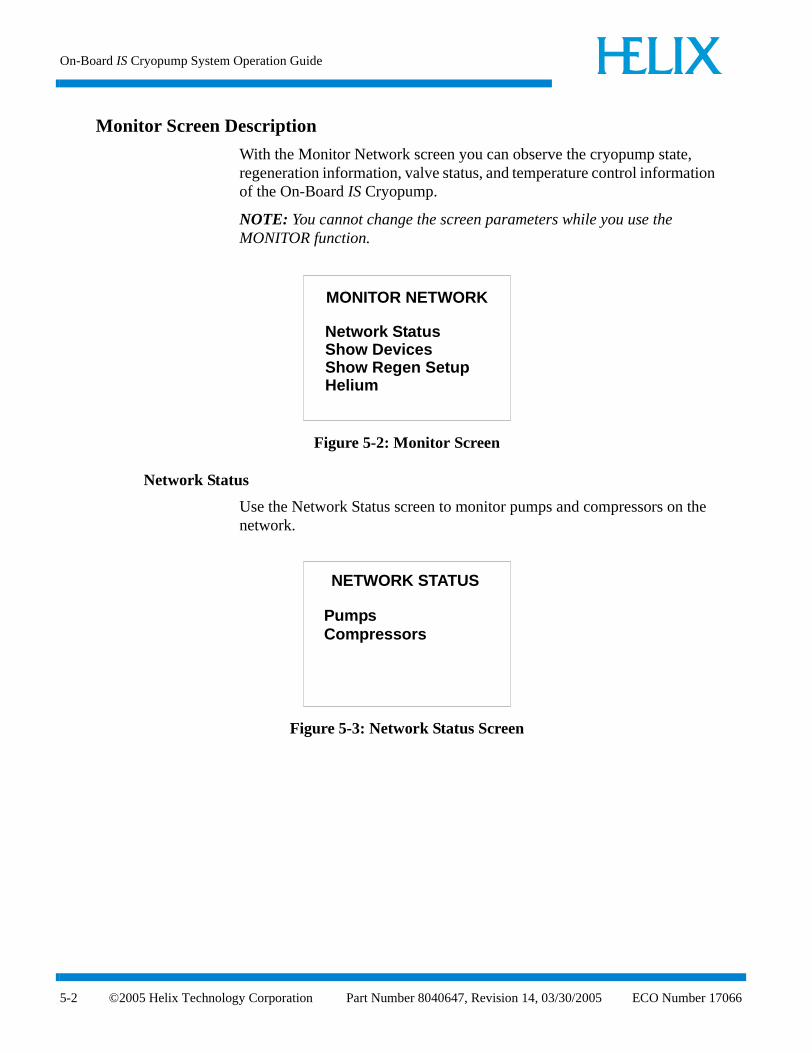
Monitor Screen Description
With the Monitor Network screen you can observe the cryopump state, regeneration information, valve status, and temperature control information of the On-Board IS Cryopump.
NOTE: You cannot change the screen parameters while you use the MONITOR function.
Figure 5-2: Monitor Screen
Network Status
Use the Network Status screen to monitor pumps and compressors on the network.
Figure 5-3: Network Status Screen
MONITOR NETWORK
Network StatusShow DevicesShow Regen SetupHelium
NETWORK STATUS
CompressorsPumps
©2005 Helix Technology Corporation Part Number 8040647, Revision 14, 03/30/2005 ECO Number 17066
Monitor Screen Description
ECO
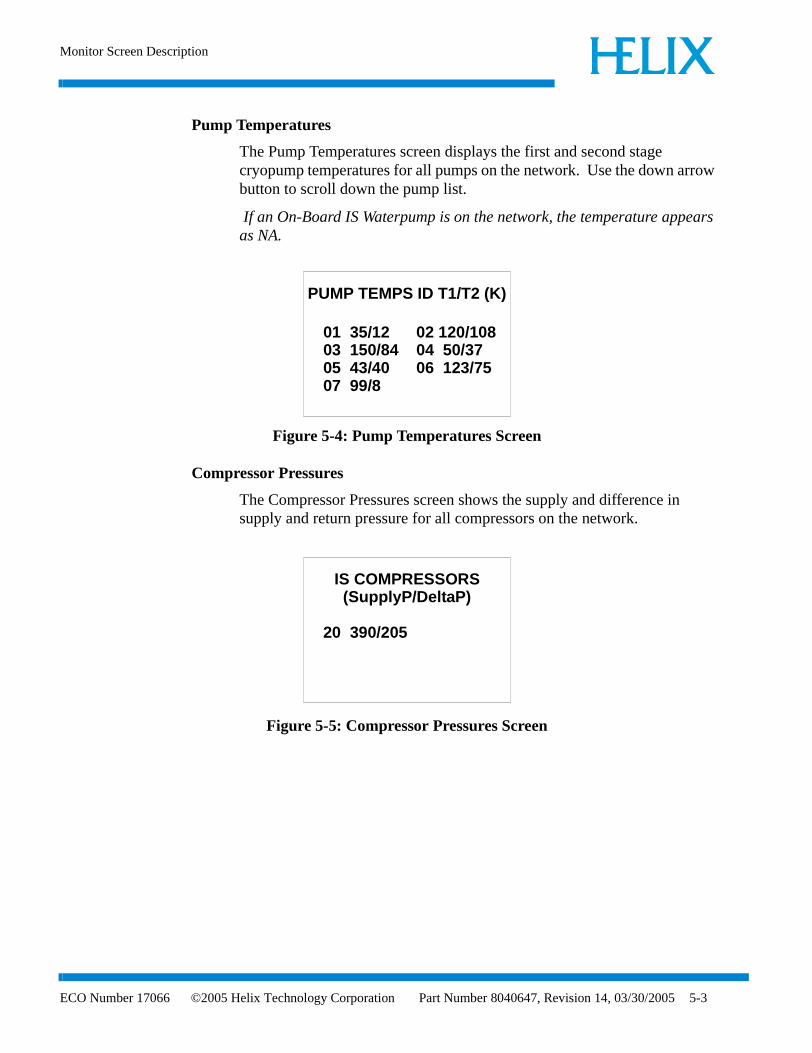
Pump Temperatures
The Pump Temperatures screen displays the first and second stage cryopump temperatures for all pumps on the network. Use the down arrow button to scroll down the pump list.
If an On-Board IS Waterpump is on the network, the temperature appears as NA.
Figure 5-4: Pump Temperatures Screen
Compressor Pressures
The Compressor Pressures screen shows the supply and difference in supply and return pressure for all compressors on the network.
Figure 5-5: Compressor Pressures Screen
PUMP TEMPS ID T1/T2 (K)
01 35/12 02 120/10803 150/84 04 50/3705 43/40 06 123/7507 99/8
IS COMPRESSORS(SupplyP/DeltaP)
20 390/205
Number 17066 ©2005 Helix Technology Corporation Part Number 8040647, Revision 14, 03/30/2005 5-3

On-Board IS Cryopump System Operation Guide
5-4
Show Devices
The Network Devices screen shows a list of equipment types and quantity of equipment on the network.
Figure 5-6: Show Devices Screen
Network Pumps
The Network Pumps screen identifies all On-Board IS Cryopumps on the network.
Figure 5-7: Network Pumps Screen
NETWORK DEVICES
Pumps 12Compressors 6
NETWORK PUMPS
00 01 02 03 0405 06 09 12 1718 19
©2005 Helix Technology Corporation Part Number 8040647, Revision 14, 03/30/2005 ECO Number 17066

Monitor Screen Description
ECO
Network Compressors
The Network Compressors screen identifies all IS 1000 Compressors on the network.
Figure 5-8: Network Compressors Screen
Show Regeneration Setup
Use the Regeneration screen to turn rough valve coordination and power failure recovery ON or OFF, and to review rough maps.
Figure 5-9: Regeneration Screen
NETWORK COMPRESSORS
20 21
REGENERATION
Coordination Full OFF Pwr Fail OFFRough Map
Number 17066 ©2005 Helix Technology Corporation Part Number 8040647, Revision 14, 03/30/2005 5-5

On-Board IS Cryopump System Operation Guide
5-6
Rough Map
The Rough Map screen shows the first of 5 rough maps.
To view additional rough maps, select NEXT MAP.
Figure 5-10: Rough Map Screen
Helium
Use the Helium Management screen to review helium maps.
Figure 5-11: Helium Management Screen
ROUGH MAP 1
00 01 02 05 0710 12 15 19
NEXT MAP
HELIUM MANAGMENT
Show Helium Maps
©2005 Helix Technology Corporation Part Number 8040647, Revision 14, 03/30/2005 ECO Number 17066

Monitor Screen Description
ECO
Show Helium Maps
The Show Helium Maps screen shows helium maps 1 through 5.
To view additional helium maps, select NEXT MAP.
Figure 5-12: Show Helium Maps Screen
HELIUM MAP 1
01 02 10 20
NEXT MAP
Number 17066 ©2005 Helix Technology Corporation Part Number 8040647, Revision 14, 03/30/2005 5-7

On-Board IS Cryopump System Operation Guide
5-8
Figure 5-13: Monitor Screens
MONITOR NETWORK
Network StatusShow DevicesShow Regen SetupHelium
NETWORK STATUS
CompressorsPumps
PUMP TEMPS ID T1/T2 (K)
01 35/12 02 120/10803 150/84 04 50/3705 43/40 06 123/7507 99/8
COMPRESSOR(SupplyP/DeltaP)
20 390/205
NETWORK DEVICES
Pumps 12Compressors 6
NETWORK PUMPS
00 01 02 03 0405 06 09 12 1718 19
NETWORK COMPRESSORS
20 21
REGENERATION
Coordination Full OFF Pwr Fail OFFRough Map
ROUGH MAP 1
00 01 02 05 0710 12 15 19
NEXT MAP
HELIUM MANAGMENT
Show Helium Maps
HELIUM MAP 1
01 02 10 20
NEXT MAP
©2005 Helix Technology Corporation Part Number 8040647, Revision 14, 03/30/2005 ECO Number 17066

Monitor Screen Description
ECO
Regeneration Screen
Use the Regeneration screen to start or abort a group regeneration cycle. The current group regeneration state also appears.
Figure 5-14: Regeneration Screen
Group Regeneration
Use the Group Regeneration to select the On-Board IS Cryopumps on the network to be regenerated.
Figure 5-15: Group Regeneration Pumps Screen
REGENERATION
StartAbortGroup Regen: OFF
CHOOSE REGEN PUMPS
00 02 03 0405 06 07 0809 14 15 1619
ENTER
Number 17066 ©2005 Helix Technology Corporation Part Number 8040647, Revision 14, 03/30/2005 5-9

On-Board IS Cryopump System Operation Guide
5-10
Regeneration List Verification
The Regeneration List Verification screen shows the previously selected On-Board IS Cryopumps to be regenerated. Then you can choose a Fast or a Full regeneration cycle.
NOTE: If NO is selected, the Regeneration screen appears.
Figure 5-16: Start Fast Regeneration Cycle Screen
Regeneration Verification Screen
Use the Regeneration Verification screen to verify the regeneration cycle selected.
Selecting YES initiates the desired regeneration cycle.
Selecting NO returns you to the previous screen.
Figure 5-17: Regeneration Verification Screen
NOTE: If the selected On-Board IS Cryopumps cannot be regenerated, a screen appears explaining the reason.
LIST TO REGEN
02 03 04 05 06 07 08
Start Fast RegenStart Full Regen
START FAST REGENAre you sure?
YESNO
©2005 Helix Technology Corporation Part Number 8040647, Revision 14, 03/30/2005 ECO Number 17066

Monitor Screen Description
ECO
Regeneration Abort
The Regeneration Abort screen verifies that you want to abort a regeneration cycle.
Selecting YES causes the regeneration cycle to be aborted. You must press the BACK button to return to the Regeneration screen.
Selecting NO causes the Regeneration Status screen to appear.
Figure 5-18: Regeneration Abort Screen
ABORT REGENERATION
Are You Sure?
YesNo
Number 17066 ©2005 Helix Technology Corporation Part Number 8040647, Revision 14, 03/30/2005 5-11

On-Board IS Cryopump System Operation Guide
5-12
Figure 5-19: Regeneration Screens
REGENERATION
StartAbortGroup Regen: OFF
CHOOSE REGEN PUMPS
00 02 03 0405 06 07 0809 14 15 1619
ENTER
START FAST REGENAre you sure?
YESNO
ABORT REGENERATION
Are You Sure?
YesNo
FASTREGEN STARTED
FAST REGEN RESPONSE
Regen Did Not StartReason:Full Regen Starting
ABORT REGENERATION
Regen Has Aborted.
LIST TO REGEN
02 03 04 05 06 07 08
Start Fast RegenStart Full Regen
©2005 Helix Technology Corporation Part Number 8040647, Revision 14, 03/30/2005 ECO Number 17066

Access Device Screen Description
ECO
Access Device Screen Description
Use the Choose Device screen to choose an individual On-Board IS Cryopump or other network device. The Choose Device display indicates the type and number of devices currently on the On-Board IS Intercomponent Network.
Figure 5-20: Choose Device Screen
Network Pumps
Use the Network Pumps screen to select a pump number from a list of pumps on the network.
Figure 5-21: Network Pump Screen
After you select a pump, the main On-Board IS Cryopump screen appears as shown in Figure 5-22.
CHOOSE DEVICE
Pumps 12Compressors 6
NETWORK PUMPS
00 01 03 05 06
13 16 18 07 08 09 10 11
Number 17066 ©2005 Helix Technology Corporation Part Number 8040647, Revision 14, 03/30/2005 5-13

On-Board IS Cryopump System Operation Guide
5-14
Figure 5-22: On-Board IS Pump Information Screen
Network Compressors
Use the Network Compressors screen to select an IS 1000 Compressor number from a list of pumps on the network.
Figure 5-23: Network Compressor Screen
After the compressor has been selected, the IS 1000 Compressor information screen appears as shown in Figure 5-24.
Figure 5-24: IS 1000 Compressor Information Screen
ON-BOARD IS CRYOPUMP
MonitorRegenerationSystem SetupControlPump Info
NETWORK COMPRESSORS
20 21 23 24
29 30
COMPRESSOR 20
Supply (psig)Return (psig)Delta (psig)Water In (F)Water Out (F)Operating (h)
378179199
7793
462
©2005 Helix Technology Corporation Part Number 8040647, Revision 14, 03/30/2005 ECO Number 17066

Access Device Screen Description
ECO
Figure 5-25: Access Network Device Screens
CHOOSE DEVICE
Pumps 12Compressors 6
NETWORK PUMPS
00 01 03 05 06
13 16 18 07 08 09 10 11
PUMP 11st Stage(K) 3502nd Stage(K) 157Vacuum(µ) OFFRegen State State Comment 1 State Comment 2
NETWORK COMPRESSORS
20 21 23 24
29 30
COMPRESSOR 20
Supply (psig)Return (psig)Delta (psig)Water In (F)Water Out (F)Operating (h)
3781791997793
462
ON-BOARD IS CRYOPUMP
MonitorRegenerationSystem SetupControlPump Info
Number 17066 ©2005 Helix Technology Corporation Part Number 8040647, Revision 14, 03/30/2005 5-15

On-Board IS Cryopump System Operation Guide
5-16
System Setup Screen Description
Through the System Setup screen, you can access regeneration, security, communication station ID, power failure, and relay subsystem configurations. The screen is password protected.
Figure 5-26: System Setup Screen
Regeneration Setup
Use the Regeneration Setup screen to configure regeneration parameters. You can also control Full coordination or power fail coordination with this screen.
Figure 5-27: Regeneration Setup Screen
SYSTEM SETUP
RegenerationPasswordCommunicationHeliumDisplay Setup
REGENERATION
Coordination Full OFF Pwr Fail OFFSelect Rough Map 1
©2005 Helix Technology Corporation Part Number 8040647, Revision 14, 03/30/2005 ECO Number 17066
System Setup Screen Description
ECO
Rough Map
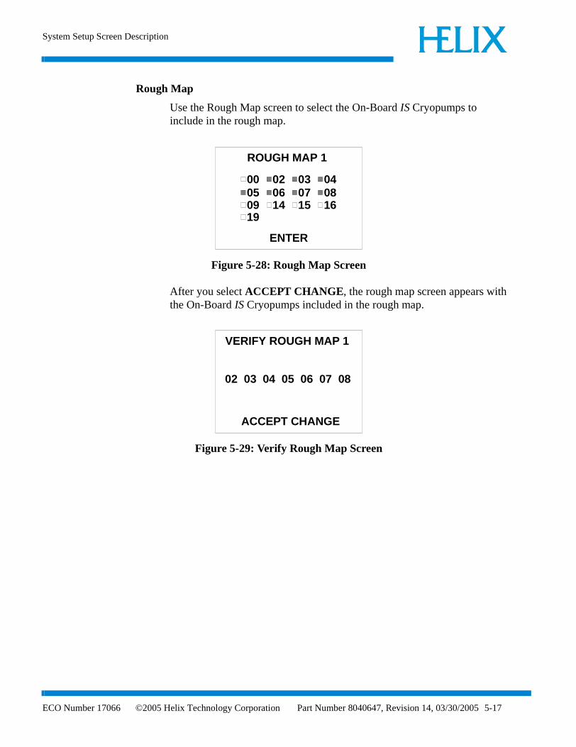
Use the Rough Map screen to select the On-Board IS Cryopumps to include in the rough map.
Figure 5-28: Rough Map Screen
After you select ACCEPT CHANGE, the rough map screen appears with the On-Board IS Cryopumps included in the rough map.
Figure 5-29: Verify Rough Map Screen
ROUGH MAP 1
00 02 03 0405 06 07 0809 14 15 1619
ENTER
VERIFY ROUGH MAP 1
02 03 04 05 06 07 08
ACCEPT CHANGE
Number 17066 ©2005 Helix Technology Corporation Part Number 8040647, Revision 14, 03/30/2005 5-17

On-Board IS Cryopump System Operation Guide
5-18
Password Setup
Use the Password Setup screen to establish or change a numeric password and enable or disable password protection.
Figure 5-30: Password Setup Screen
When password protection is turned ON, you are prompted to enter a password to access IS Controller software.
Figure 5-31: Entering a Password Screen
After you enter a password, a password confirmation screen appears.
Figure 5-32: Confirm Password Screen
PASSWORD SETUP
Protection OFFChange Password
ENTER PASSWORD(A Number 1-32767)
* * * * *
CONFIRM PASSWORD(A Number 1-32767)
* * * * *
©2005 Helix Technology Corporation Part Number 8040647, Revision 14, 03/30/2005 ECO Number 17066

System Setup Screen Description
ECO
Password Reset
If you forget a password, you can reset it to a factory default value of 9999.
Use the password reset function from the Main screen by pressing the Left and Right arrow keys simultaneously.
A password verification screen appears to verify the password must be reset. Answering Yes resets the password to 9999. Answering NO does not change the password.
Communication
Use the Communication screen to set the communication baud rate to the IS Controller.
Baud Rate
The IS Controller determines which ports are available (a minimum of two and maximum of three) and lists the ports on the Communication screen.
Figure 5-33: Communication Baud Rate Screen
COMMUNICATION
HostService
Set Port BAUD Rate:
Aux
960096009600
Number 17066 ©2005 Helix Technology Corporation Part Number 8040647, Revision 14, 03/30/2005 5-19

On-Board IS Cryopump System Operation Guide
5-20
Helium
Use the Helium screen to select which helium map to configure. Enter the number of the helium map and press enter to view the helium map.
Figure 5-34: Choosing Helium Maps Screen
Choose Helium Map for Pumps
Use the Choose Map Pumps screen to select which On-Board IS Cryopumps are included in the helium map.
Figure 5-35: Choosing Helium Maps Screen
HELIUM
Select Helium Map 1
CHOOSE MAP PUMPS
00 02 03 0405 06 07 0809 14 15 1619
ENTER
©2005 Helix Technology Corporation Part Number 8040647, Revision 14, 03/30/2005 ECO Number 17066

System Setup Screen Description
ECO
Choose Helium Map for Compressors
Use the Choose Compressors screen to select which On-Board IS Compressors are included in the helium map.
Figure 5-36: Choosing Helium Maps Screen
Verify Helium Map Setup
Use the Verify Helium Map Setup screen to verify and accept the On-Board IS Cryopumps and IS 1000 Compressors in the helium map.
Figure 5-37: Verify Helium Map Screen
CHOOSE COMPRESSORS
20 21 28
ENTER
VERIFY HELIUM MAP 1
Pumps/Compressors:02 04 06 0721
ACCEPT CHANGE
Number 17066 ©2005 Helix Technology Corporation Part Number 8040647, Revision 14, 03/30/2005 5-21

On-Board IS Cryopump System Operation Guide
5-22
Display Setup
Use the IS Remote Setup screen to configure the On-Board IS Remote parameters. Refer to Table 5-1 for parameter values.
Figure 5-38: On-Board IS Remote Setup Screen
Table 5-1: IS Remote Setup Parameters
Parameter Default Value Range of Values
Brightness 0 0 (Brightest) - 15
Volume 16 0 - 16 (Loudest)
Screen Time-out 15 0 - 60 minutes
IS REMOTE SETUP
BrightnessVolumeScreen Time outSet Default
55
60
RD Ver. X.X
©2005 Helix Technology Corporation Part Number 8040647, Revision 14, 03/30/2005 ECO Number 17066

System Setup Screen Description
ECO
Figure 5-39: System Setup Screens
SYSTEM SETUP
RegenerationPasswordCommunicationHelium
REGENERATION SETUP
Coordination Full OFF Pwr Fail OFFRough Map 1
ROUGH MAP 1
00 02 03 0405 06 07 0809 14 15 1619
ENTER
VERIFY ROUGH MAP 1
02 03 04 05 06 07 08
PASSWORD SETUP
Protection OFFChange Password
ENTER PASSWORD(A Number 1-32767)
CONFIRM PASSWORD(A Number 1-32767)
CHOOSE MAP PUMPS
00 02 03 0405 06 07 0809 14 15 1619
ENTER
CHOOSE COMPRESSORS
20 21 28
ENTER
VERIFY HELIUM MAP 1
Pumps/Compressors:02 04 06 0721
ACCEPT CHANGE
IS REMOTE SETUP
BrightnessVolumeScreen Time outSet Default
55
60
HELIUM
Helium Map 1
RD Ver. X.X
* * * * *
* * * * *
ACCEPT CHANGE
COMMUNICATION
HostService
Set Port BAUD Rate:
Aux
960096009600
Number 17066 ©2005 Helix Technology Corporation Part Number 8040647, Revision 14, 03/30/2005 5-23

On-Board IS Cryopump System Operation Guide
5-24
©2005 Helix Technology Corporation Part Number 8040647, Revision 14, 03/30/2005 ECO Number 17066
Introduction
ECO
Section 6 - Using On-Board IS Cryopump Screens
Introduction
This section describes how to program and operate the On-Board IS FastRegen Control Module software. You can do this when the On-Board IS Remote is connected to a specific On-Board IS Cryopump.
The On-Board IS Cryopump Module contains factory-set parameters. If you must change the default parameters, then connect the Remote Display to each On-Board IS Cryopump.
Selecting Screens and Changing Parameters
Select Screens and change values the same way, regardless of the screen. Use the following procedures to select screens and change values on the Remote Display shown in Figure 6-1.
Figure 6-1: On-Board IS Remote
Screen Selection
1. Use the arrow buttons to select a screen.
2. Press the ENTER button. The selected screen appears.
3. Use the arrow buttons to move the cursor to an item.
4. Press the ENTER button. The selected screen appears.
Changing a Screen Parameter
1. Use the arrow buttons to select a screen.
?
ENTER
ON-BOARD IS CRYOPUMP
MonitorRegenerationSystem SetupControlPump Info
Number 17066 ©2005 Helix Technology Corporation Part Number 8040647, Revision 14, 03/30/2005 6-1

On-Board IS Cryopump System Operation Guide
6-2
2. Press the ENTER button. The selected screen appears.
3. Use the arrow buttons to move the cursor under the parameter you want to change.
4. Press the ENTER button. The parameter is underlined.
5. Use the arrow buttons to change the value.
6. Press the ENTER button. The parameter changes to the new value.
When the On-Board IS Remote is idle for 15 minutes, a screen saver appears, and dim the display to its lowest level. Pressing any button on the remote display turns off the screen saver and returns the screen to its normal brightness.
Monitor Function
Use the Monitor function to observe the cryopump state, regeneration information, valve status, and temperature control information of the On-Board IS Cryopump.
NOTE: You cannot change screen parameters while you use the Monitor function.
Figure 6-2: Monitor Screen
NOTE: Relay Status is available on Implant cryopumps only.
Pump State
Use the Pump State screen to view T1 and T2 temperatures, Cryopump thermocouple gauge, and the current regeneration state. This information is continuously updated.
If the temperature of the first or second goes below 5K, the display indicates Open.
If the temperature of the first or second goes above 350K, the display indicates Short.
MONITOR
Pump StateRegeneration InfoValve StatusTemperature ControlRelay Status
©2005 Helix Technology Corporation Part Number 8040647, Revision 14, 03/30/2005 ECO Number 17066

Monitor Function
ECO
If the Cryopump thermocouple gauge is disabled, the display indicates OFF.
Figure 6-3: Pump State Screen
Regeneration Information
The Regeneration Information screen displays the current state of the Rough Valve Coordination feature and the time since the last Fast and Full regeneration cycle.
Figure 6-4: Regeneration Information Screen
Valve Status
The Valve Status screen displays the status of the rough, pump purge, exhaust purge, and gate valves.
Figure 6-5: Valve Status Screen
PUMP STATE1st Stage (K) XXX2nd Stage (K) XXXVacuum (µ) XXX
Regen Status Full in progress
XXXPump OFF
REGENERATION
Rough Valve Coord ON
INFORMATION
Time Since...Last Full (h) XXX hrsLast Fast (h) XXX hrs
VALVE STATUS
RoughPump PurgeExhaust Purge
Closed
Gate
ClosedClosedClosed
Number 17066 ©2005 Helix Technology Corporation Part Number 8040647, Revision 14, 03/30/2005 6-3

On-Board IS Cryopump System Operation Guide
6-4
Temperature Control
The Temperature Control screen displays the first and second stage temperatures and set point values.
Figure 6-6: Temperature Control Screen
NOTE: 2nd Stage is available on Implant cryopumps only.
Relay Status
The Relay Status screen shows the status of the warmup relay, On or Off.
Figure 6-7: Relay Status Screen
NOTE: Relay Status is available on Implant cryopumps only.
TEMPERATURE
1st Stage
CONTROL
Set point (K)
2nd Stage
ON
ON
100
RELAY STATUS
Warmup Relay OFF
©2005 Helix Technology Corporation Part Number 8040647, Revision 14, 03/30/2005 ECO Number 17066

Monitor Function
ECO
Figure 6-8: Monitor Function Screens
Regeneration Screen
Use the Regeneration screen to start a Fast or Full regeneration cycle, or abort a cycle that is running. If a regeneration cycle is being aborted, the user will be asked to confirm the abort.
Note that the screen is password protected if the password option on the Security screen in ON.
For regeneration parameters, see Table B-1.
Figure 6-9: Regeneration Screen
Start Full Regeneration
The Start Full Regeneration screen requires you to confirm the start of a Full regeneration cycle.
If NO is selected, the Regeneration screen appears.
PUMP STATE
1st Stage (K) XXX2nd Stage (K) XXXVacuum (µ) XXXRegen Status Full in progress
REGENERATION
Rough Valve Coord ON
INFO.
Time Since...Last Full XXX hrsLast Fast XXX hrs
MONITOR
Pump StateRegeneration InfoValve StatusTemperature ControlRelay Status
VALVE STATUS
RoughPump PurgeExhaust Purge
Closed
Gate
ClosedClosedClosed
TEMPERATURE
1st Stage
CONTROL
Set point (K)
2nd Stage
ON
ON
100
REGENERATION
Start FullStart Fast
Number 17066 ©2005 Helix Technology Corporation Part Number 8040647, Revision 14, 03/30/2005 6-5

On-Board IS Cryopump System Operation Guide
6-6
Figure 6-10: Start Full Regeneration Cycle Screen
Start Fast Regeneration
The Start Fast Regeneration screen requires you to confirm the start of a Fast regeneration cycle.
If NO is selected, the Regeneration screen appears.
Figure 6-11: Start Fast Regeneration Cycle Screen
START FULL REGEN
Are you sure?
NoYes
START FAST REGEN
Are you sure?
NoYes
©2005 Helix Technology Corporation Part Number 8040647, Revision 14, 03/30/2005 ECO Number 17066

Monitor Function
ECO
Regeneration Status
The Regeneration Status screen is constantly updated while the current regeneration cycle is in progress. The regeneration cycle can also be aborted from this screen. If a regeneration cycle is being aborted, you must confirm the command.
Figure 6-12: Regeneration Status Screen
Regeneration Abort
The Regeneration Abort screen verifies that you want to abort a regeneration cycle.
If YES is selected, the regeneration cycle is aborted. You must press the BACK button to return to the Regeneration screen.
If NO is selected, the Regeneration Status screen appears.
Figure 6-13: Regeneration Abort Screen
REGENERATION STATUSXXXX in Progress
Regen StatusRegen messages hereRegen messages here
Abort
ABORT REGENERATION
Are you sure?
NoYes
Number 17066 ©2005 Helix Technology Corporation Part Number 8040647, Revision 14, 03/30/2005 6-7
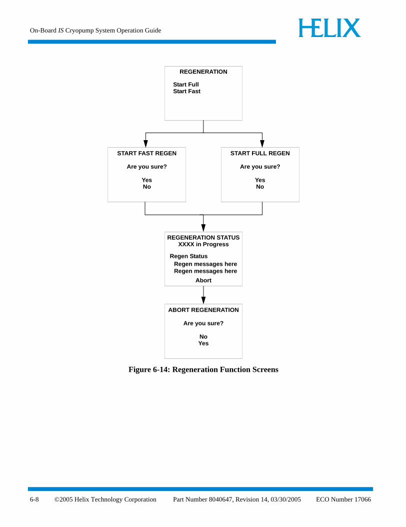
On-Board IS Cryopump System Operation Guide
6-8
Figure 6-14: Regeneration Function Screens
REGENERATION
Start FullStart Fast
START FULL REGEN
Are you sure?
YesNo
START FAST REGEN
Are you sure?
YesNo
REGENERATION STATUSXXXX in Progress
Regen StatusRegen messages hereRegen messages here
Abort
ABORT REGENERATION
Are you sure?
NoYes
©2005 Helix Technology Corporation Part Number 8040647, Revision 14, 03/30/2005 ECO Number 17066

System Setup Function
ECO
System Setup Function
The System Setup screen provides access to regeneration, security, communication station ID, power failure, and relay subsystem configurations. The screen is password protected.
Figure 6-15: PVD System Setup Screen
Figure 6-16: Implant System Setup Screens
To see all the options on the Implant system setup screens, press the up or down arrows as necessary. Figure 6-16 shows both possible system setup screens.
SYSTEM SETUP
RegenerationSecurity ConfigCommunicationStation IDPower FailureDisplay Setup
SYSTEM SETUP
RegenerationSecurity ConfigCommunicationStation IDPower FailureRelay Setup
SYSTEM SETUP
Relay Setup
Security ConfigCommunicationStation IDPower Failure
Display Setup
Number 17066 ©2005 Helix Technology Corporation Part Number 8040647, Revision 14, 03/30/2005 6-9

On-Board IS Cryopump System Operation Guide
6-10
Regeneration Setup
Use the Regeneration Setup screen to select the Purge, Rough, and Regeneration Delay sub screens.
Figure 6-17: Regeneration Setup Screen
Purge Setup
Use the Purge Setup screen to set the extended time, repurge time and number of repurge cycles. The purge setup values appear in Table B-2.
Figure 6-18: Purge Setup Screen
Rough Setup
Use the Rough Setup screen to set the base pressure, maximum rate-of-rise, maximum rate-of-rise cycles, rough test values, and turn Rough Coordination ON or OFF. The Rough Setup values appear in Table B-3.
REGENERATION SETUP
PurgeRoughingDelay
PURGE SETUP
Extended (m) Repurge (m)Repurge Cycles
XXXXXX XX
©2005 Helix Technology Corporation Part Number 8040647, Revision 14, 03/30/2005 ECO Number 17066

System Setup Function
ECO
Figure 6-19: Rough Setup Screen
Delay Setup
Use the Delay Setup screen to set the start delay and restart delay parameters. The Delay Setup parameters appear in Table 6-1.
Figure 6-20: Delay Setup Screen
Table 6-1: Delay Setup Parameters
Parameter Minimum Maximum Units
Start Delay 0 999.9 Minutes
Re-Start Delay 0 999.9 Minutes
ROUGH SETUP
Base Pressure (µ)ROR Max (µ/min)ROR CyclesRough Test (s)Rough Coord
XXXXXXXXXXXOFF
DELAY SETUP
Start DelayRestart Delay
(h) XXX.X
(h) XXX.X
Number 17066 ©2005 Helix Technology Corporation Part Number 8040647, Revision 14, 03/30/2005 6-11
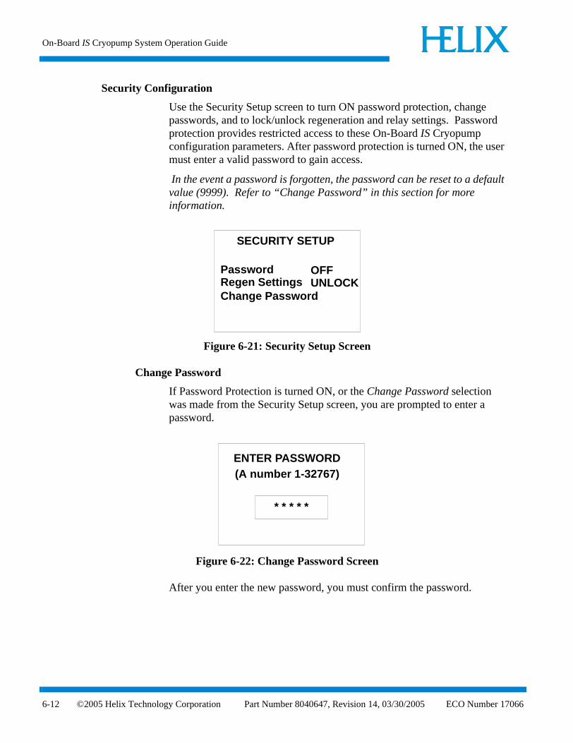
On-Board IS Cryopump System Operation Guide
6-12
Security Configuration
Use the Security Setup screen to turn ON password protection, change passwords, and to lock/unlock regeneration and relay settings. Password protection provides restricted access to these On-Board IS Cryopump configuration parameters. After password protection is turned ON, the user must enter a valid password to gain access.
In the event a password is forgotten, the password can be reset to a default value (9999). Refer to “Change Password” in this section for more information.
Figure 6-21: Security Setup Screen
Change Password
If Password Protection is turned ON, or the Change Password selection was made from the Security Setup screen, you are prompted to enter a password.
Figure 6-22: Change Password Screen
After you enter the new password, you must confirm the password.
SECURITY SETUP
PasswordRegen SettingsChange Password
OFFUNLOCK
ENTER PASSWORD
* * * * *
(A number 1-32767)
©2005 Helix Technology Corporation Part Number 8040647, Revision 14, 03/30/2005 ECO Number 17066

System Setup Function
ECO
Communication
Use the Communication Setup screen to configure the baud rate of the external RS-232 port. The baud rate values are listed in Table 6-2.
Figure 6-23: Communication Setup Screen
Station ID
Use the station ID screen to identify the vacuum system chamber on which the On-Board IS Cryopump has been installed.
Figure 6-24: Station ID Setup Screen
Table 6-2: Communication Baud Rate Values
Parameter Choices
Baud Rate 2400, 9600, 19200, 38400
COMMUNICATION
Host 9600
Set Port Baud Rate
Service 9600
STATION ID SETUP
Station ID abcedfgh
Number 17066 ©2005 Helix Technology Corporation Part Number 8040647, Revision 14, 03/30/2005 6-13

On-Board IS Cryopump System Operation Guide
6-14
Power Failure
Use the Power Failure setup screen to configure power failure parameters. Choices for recovery are; ON, OFF (PVD cryopumps only), and Cool.
If ON is selected and the power is interrupted and then restored, the second stage temperature is monitored.
If the current temperature of the second stage exceeds the power fail temperature limit, a regeneration cycle is performed.
The range of temperature values are listed in Table B-4.
If you use an Implant cryopump, see Section 4 - IntelliPurge for information about power failure recovery, and pump behavior.
Figure 6-25: Power Failure Screen
Relay Setup
Use the relay setup screen to configure the warm-up alarm relay. You can set a value between 20 and 34K inclusive. After the cryopump completes regeneration, the warm-up alarm relay is ready to respond to unexpected temperature rises in the second stage.
If the cryopump temperature exceeds the set point value, then the relay state changes from de-energized to energized. Use the RELAY SETUP screen to adjust the set point, shown in Figure 6-26. Access the relay contacts through the IntelliPurge module interface (see Section 4 - IntelliPurge). The pin description of the IntelliPurge module interface are in the On-Board IS Installation Instructions, part number 8040596.
POWER FAILURE
Recovery ONTemperature (K) XX
©2005 Helix Technology Corporation Part Number 8040647, Revision 14, 03/30/2005 ECO Number 17066

System Setup Function
ECO
Figure 6-26: Relay Setup Screen
IS Remote Setup (Display Setup)
Use the IS Remote Setup screen to configure the On-Board IS Remote Display parameters. Refer to Table 6-3 for parameter values.
Figure 6-27: Display Setup Screen
Table 6-3: Display Setup Parameters
Parameter Default Value Range of Values
Brightness 0 0 (Brightest) - 15
Volume 16 0 - 16 (Loudest)
Screen Time-out 15 0 - 60 minutes
RELAY SETUP
Warmup Relay (K) 25
IS REMOTE SETUP
BrightnessVolumeScreen Time-outSet Default
55
60
RD Ver. 0.0
Number 17066 ©2005 Helix Technology Corporation Part Number 8040647, Revision 14, 03/30/2005 6-15

On-B
oard IS Cryopum
p System O
peration Guide
6-16©
2005 Helix T
echnology Corporation
Part Num
ber 8040647, Revision 14, 03/30/2005 E
CO
Num
ber 17066
IS REMOTE SETUP
BrightnessVolumeScreen Time-outSet Default
55
60
ELAY SETUP
p Relay (K) 25
*See Figure 6-15 for the PVD Screen.**Only available with Implant cryopumps.
Figure 6-28: System Setup Function Screens
REGENERATION SETUP
PurgeRoughingDelay
PURGE SETUP
Extended (m) Repurge (m)Repurge Cycles
XXXXXX 99
ROUGHING SETUP
Base Pressure (µ)ROR Max (µ/min)ROR CyclesRough Test (s)Rough Coord
XXXXXXXXXXXXOFF
DELAY SETUP
Start DelayRe-Start Delay
(h) XXX.X
(h) XXX.X
SECURITY SETUP
PasswordRegen SettingsChange Password
OFFUNLOCK
STATION ID SETUP
Station ID abcedfgh
POWER FAILURE
Recovery ONTemperature (K) XX
COMMUNICATION
Host 9600
Set Port Baud Rate
Service 9600
ENTER PASSWORD
* * * * *
(A number 1-32767)
R
Warmu
SYSTEM SETUP
RegenerationSecurity ConfigCommunicationStation IDPower FailureRelay Setup
SYSTEM SETUP
Relay Setup
Security ConfigCommunicationStation IDPower Failure
Display Setup
*
**

Control Function
ECO
Control Function
Use the Control function to turn on the On-Board IS Cryopump motor, thermocouple gauge and relays ON or OFF, and open or close the rough and purge valves. The Control parameters appear in Table 6-4 for PVD cryopumps, Table 6-5 for Implant pump controls and Table 6-6 for Implant valve controls.
Figure 6-29: PVD Control Screen
NOTE: You cannot use the Control Function to turn on the Cryo TC when the On-Board IS Cryopump second stage temperature is above 20K.
Also, to prevent possible cryopump contamination, you cannot use the Control Function to open the Rough or Purge valves when the On-Board IS Cryopump motor is ON.
Figure 6-30: Implant Control Screen
Table 6-4: PVD Control Parameters
Parameter Value
Motor ON/OFF
Cryo TC ON/OFF
Rough Valve Open/Closed
Purge Valve Open/Closed
PUMP CONTROL
MotorCryo TCRough ValvePurge Valve
OnOffOpenClosed
HFI Status OK
CONTROL
Pump ControlValve Control
Number 17066 ©2005 Helix Technology Corporation Part Number 8040647, Revision 14, 03/30/2005 6-17

On-Board IS Cryopump System Operation Guide
6-18
Pump Control, Implant Only
Use the pump control function to start the On-Board IS Cryopump, use safe shutdown, turn on the motor, and thermocouple gauge and relays ON or OFF. The pump control parameters appear in Table 6-5.
Figure 6-31: Control Screen
Safe Shutdown
After choosing safe shutdown from the pump control screen, the following screen appears:
Figure 6-32: Control Screen
For more information about safe shutdown and the IntelliPurge system in which it is used, see Section 4 - IntelliPurge.
Table 6-5: Implant Pump Control Parameters
Parameter Value
Motor ON/OFF
Cryo TC ON/OFF
PUMP CONTROL
MotorCryo TCHFI Status
Safe ShutdownStartup
This will start a Shut Down Regen.
Do you want to proceed?
NoYes
©2005 Helix Technology Corporation Part Number 8040647, Revision 14, 03/30/2005 ECO Number 17066

Valve Control, Implant Only
ECO
Valve Control, Implant Only
For On-Board IS Implant cryopumps, you can control the pump purge and exhaust purge valves independently from all other valves on the cryopump. These two valves are listed separately on the valve control screen. You can also manage gate valve control through this screen. The valve control parameters appear in Table 6-6.
Figure 6-33: Valve Control Screen
Gate Valve
A gate valve error can be the result of four possible error states. The control screen shows ERROR if any of the following conditions exist:
• The gate valve sensors indicate that it is open, but it should be closed.
• The gate valve sensors indicate that it is closed, but it should be open.
• The gate valve sensors indicate that it is in transition, but it should be open or closed.
• The gate valve sensors indicate that it is both open and closed at the same time.
Table 6-6: Implant Valve Control Parameters
Parameter Value
Rough Valve Open/Closed
Pump Purge Valve Open/Closed
Exhaust Purge Valve Open/Closed
Gate ValveOpen/Closed/
Error/Transition
VALVE CONTROL
RoughPump PurgeExhaust Purge
Closed
Gate
ClosedClosedClosed
Number 17066 ©2005 Helix Technology Corporation Part Number 8040647, Revision 14, 03/30/2005 6-19

On-Board IS Cryopump System Operation Guide
6-20
To clear a gate valve error, ensure the gate valve control cable is properly installed (see the On-Board IS Installation Instructions, part number 8040596). Then acknowledge the gate valve error by pressing the ENTER key. The following screen appears.
Figure 6-34: Gate Valve Error Clearing Screen
If the problem causing the gate valve error has been corrected, use the arrow keys to select YES and press ENTER. The cryopump attempts to close the gate valve and confirm (through the gate valve sensors) that the gate valve is closed. If this is successful, then normal operation can resume. If it is not successful, then the gate valve returns to the error state.
This will clear the
Do you want to proceed?NoYes
(This could take several seconds)
error and close the Gate Valve.
©2005 Helix Technology Corporation Part Number 8040647, Revision 14, 03/30/2005 ECO Number 17066

Introduction
ECO
Section 7 - Troubleshooting Procedures
Introduction
Section 6 provides information on how to troubleshoot Helix Intercomponent Network communication problems and provides references to on-line product manuals for troubleshooting the On-Board IS Cryopump or IS 1000 Compressor.
NOTE: You can also refer to Appendix A for customer support information and contact Helix Technology Corporation for assistance if required.
Helix Intercomponent Network
Refer to Table 7-1 if you are experiencing Helix Intercomponent Network communication problems.
Table 7-1: Helix Intercomponent Network Troubleshooting Procedures
Problem Possible Cause Corrective Action
1. On-Board IS Cryopumps are not visible on IS Controller screens.
1. A network terminator is not installed in the last cryopump on channel A or B.
2. The cryopump is connected to channel C.
3. Defective network cable.
1. Refer to the On-Board IS Cryopump Quick Installation Guide and install a network terminator in the last cryopump on channels A or B.
2. Disconnect the cryopump from channel C and connect it to channels A or B.
3. Replace network cable.
Number 17066 ©2005 Helix Technology Corporation Part Number 8040647, Revision 14, 03/30/2005 7-1

On-Board IS Cryopump System Operation Guide
7-2
2. Compressors are not visible on On-Board IS Controller screens.
1. A network terminator is not installed in the last compressor on channel C.
2. The compressor is connected to channels A or B.
3. Defective network cable.
1. Refer to the On-Board IS 1000 Compressor Quick Installation Guide and install a network terminator in the last compressor on channel C.
2. Disconnect the compressor from channels A or B and connect it to channel C.
3. Replace network cable.
3. Status LED III on the IS Controller is not blinking.
1. Channel A, B or C network cable is disconnected from controller.
2. Defective network cable.
1. Connect the network cable(s) to the controller.
2. Replace network cable.
Table 7-1: Helix Intercomponent Network Troubleshooting Procedures (Continued)
Problem Possible Cause Corrective Action
©2005 Helix Technology Corporation Part Number 8040647, Revision 14, 03/30/2005 ECO Number 17066

Customer Support Center Locations
ECO
Appendix A - Customer Support Information
Customer Support Center Locations
To locate a Customer Support Center near you, please visit our website www.helixtechnology.com on the world wide web and select CONTACT on the home page.
Guaranteed Up-Time Support (GUTS)
For 24 hour, 7 day per week Guaranteed Up-Time Support (GUTS) dial:
800-367-4887 - Inside the United States of America
508-337-5599 - Outside the United States of America
Product Information
Please have the following information available when calling so that we may assist you:
• Product Part Number
• Product Serial Number
• Product Application
• Specific Problem Area
• Hours of Operation
• Equipment Type
• Vacuum System Brand/Model/Date of Manufacture
For your convenience, you may also e-mail us at:
Number 17066 ©2005 Helix Technology Corporation Part Number 8040647, Revision 14, 03/30/2005 A-1

On-Board IS Cryopump System Operation Guide
A-2
©2005 Helix Technology Corporation Part Number 8040647, Revision 14, 03/30/2005 ECO Number 17066
Default Regeneration Parameters
ECO
Appendix B - System Parameters
Default Regeneration Parameters
The following table shows the default settings for regeneration. To change these settings, see Performing Regeneration. The check mark ( ) in the Fast and Full columns in Table B-1 indicates whether the regeneration parameters are used during the Fast and/or Full regeneration cycles.
*You cannot turn off the Power Fail Recovery feature for On-Board IS Cryopumps designed for Ion Implant processes. Only ON and COOL are available.
‡For On-Board IS Cryopumps designed for Ion Implant processes.
Table B-1: Default Regeneration Parameters
Regeneration Parameter
Default Value PVD
Applications
Default Value Implant
ApplicationsRange of Values Fast Full
Extended Purge 1 minute 60 minute 0 - 9999 minutes
Repurge 15 minutes 5 minutes 0 - 9999 minutes
Repurge Cycles 15 10 0 - 20 cycles
Base Pressure 50 microns 50 microns 25 - 200 microns
Rate-of-Rise (ROR) 10 microns/minute
10 microns/minute
1 -100 microns/minute
ROR Cycles 20 40 0 - 40 cycles
Fast Rough Test 150 seconds 500 seconds 10 - 999 seconds
Rough Coordination OFF OFF ON/OFF
Start Delay 0 0 0 - 999.9 hours
Restart Delay 0 0 0 - 999.9 hours
Power Fail Recovery OFF COOL ON/OFF/COOL*
Power Fail Recovery Temperature
25K 25K 0 - 80K, 0 - 34K‡
Number 17066 ©2005 Helix Technology Corporation Part Number 8040647, Revision 14, 03/30/2005 B-1

On-Board IS Cryopump System Operation Guide
B-2
Purge Setup Parameters
Rough Setup Prameters
Power Failure Temperature Range
Table B-2: Purge Setup Parameters
Parameter Minimum Maximum Units
Extended Purge 0 9999 Minutes
RePurge 0 9999 Minutes
Repurge Cycles 0 20 Cycles
Table B-3: Rough Setup Parameters
Parameter Minimum Maximum Units
Base Pressure 25 200 Microns
Rate of Rise 1 100 Microns/Minute
Rate of Rise Cycles 0 40 Cycles
Fast Rough Test 10 999 Seconds
Table B-4: Power Failure Temperature Ranges
Parameter Minimum Maximum Units
Temperature 0 80 K
©2005 Helix Technology Corporation Part Number 8040647, Revision 14, 03/30/2005 ECO Number 17066

ECO
Index
AAddressverifying 1-8
Address switch 1-4
C
Controllermonitor screen 5-2
Controller main screendescription 5-1
Controller network devices screendescription 5-4
Controller network status screendescription 5-2
Controller pump termperature screendescription 5-3
Controller screensaccess device 5-13choose helium map compressors 5-21choose helium map pumps 5-20compressor pressures 5-3group regeneration 5-9helium management 5-6network compressors 5-5, 5-14network devices 5-4network pumps 5-4, 5-13password setup 5-18regeneration abort 5-11regeneration list verification 5-10regeneration setup 5-16regeneration verification 5-10regeneration, description 3-1rough map 5-6show helium maps 5-7system setup 5-16verify helium map setup 5-21
Cryopumpmonitor function 6-2
Cryopump Parameters, screenchanging 6-1
Cryopump screenschange password 6-12
Number 17066 ©2005 Helix Technology Corporation P
communication setup 6-13control function 6-17, 6-18delay setup 6-11IS remote setup 6-15power failure 6-14pump state screen 6-2purge setup 6-10regeneration abort 6-7regeneration information 6-3regeneration screen 6-5regeneration setup 6-10regeneration status 6-7rough setup 6-10security setup 6-12selecting and changing parameters 6-1start fast regeneration 6-6start full regeneration 6-5station ID 6-13system setup function 6-9temperature control 6-4valve status 6-3
E
Equipment addressverifying 1-8
H
Helium mapscreating 2-5using 2-3
Helix Intercomponent Networkaddress settings 1-2network terminator 1-3On-Board IS 1000 Compressor 1-2On-Board IS Cryopumps 1-2
M
Monitor function 6-2
O
On-Board IS 1000 Compressordelta pressure 1-10
art Number 8040647, Revision 14, 03/30/2005 Index-1

On-Board IS Cryopump System Operation Guide
Index
helium supply and return pressure 1-10operating hours 1-10water in/out temperature 1-10
On-Board IS Cryopumpfirst and second stage temperatures 1-9
On-Board IS Remote 1-5
P
Parameterschanging 1-5
Powerturning on 1-6
R
Regenerationfull regeneration cycle 3-6parameters 3-2Regeneration Maps 3-4
Roughing mapsusing 2-1
Rouging mapscreating 2-3
S
Safety precautions 1-1Screen savers 1-5Screens
selecting 1-5Switch
address 1-4
T
Troubleshooting 7-1
V
verifies 5-11
-2 ©2005 Helix Technology Corporation Part Number 8040647, Revision 14, 03/30/2005 ECO Number 17066