on-board 8f cryopump for 300mm pvd module … ®, polycold® ... figure 3-8: relay 2 automatic or...
TRANSCRIPT

On-Board® 8F Cryopump for 300mm PVD
Module Programming and Operation Instructions
8040511 Revision AA
On-Board 8F Cryopump for 300mm PVD Module Programming and Operation Instructions
Brooks Automation8040511 Revision AA
Information provided within this document is subject to change without notice, and although believed to be accurate, Brooks Automation assumes no responsibility for any errors, omissions, or inaccuracies.
AcuLigner™, Align™, AquaTran™, AutoTeach™, ATR™, AXM™, Basic Blue™, BiSymmetrik™, CenterSmart™, Cool Solutions™, Crate to Operate™, e-RMA™, e-Spares™, e-Volution™, FastRegen™, FIXLOAD™, FrogLeg™, InLigner™, InCooler™, Interface™, Jet Engine™, LowProfile™, M2 Nano™, Mini-Ion™, PASIV™, PowerPak™, PerformanceBlue™, PowerPak™, PowerTools™, QuadraFly™, Radius™, Radient™, Radient Express™, Reliance™, Reliance ATR™, RetroEase™, SCARA™, SmartPM™, SPOTLevel™, Synetics™, The New Pathway to Productivity™, Time Optimized Trajectory™, Time Optimal Trajectory™, Time Optimized Path™, TopCooler™, TopLigner™, Ultimate Blue™, VAC-407™, VacuTran™, Vacuum Quality Monitor™, VQM™, Vacuum Quality Index™, VQI™, and the Brooks logo are trademarks of Brooks Automation, Inc. AcuTran®, AquaTrap®, Conductron®, Convectron®, the Cool Solutions logo, Cryodyne®, Cryotiger®, Cryo-Torr®, Fusion®, GOLDLink®, Granville-Phillips®, Guardian®, GUTS®, Helix®, Jet®, Leapfrog®, MagnaTran®, MapTrak®, Marathon®, Marathon 2®, Marathon Express®, Micro-Ion®, MiniConvectron®, On-Board®, Polycold®, Razor®, Simplicity Solutions®, the Simplicity Solutions logo, Stabil-Ion®, TrueBlue®, TurboPlus®, Vision®, Zaris®, and the Brooks Automation logo are registered U.S. trademarks of Brooks Automation, Inc. All other trademarks are properties of their respective owners.
© 2013 Brooks Automation, Inc. All Rights Reserved. The information included in this manual is Proprietary Information of Brooks Automation and is provided for the use of Brooks Automation customers only and cannot be used for distribution, reproduction, or sale without the express written permission of Brooks Automation. This information may be incorporated into the user documentation, however any changes made by the user to this information is the responsibility of the user.
For Technical Support:
Visit us online: www.brooks.com
January 15, 2013 Part Num 8040511 Revision AA
This technology is subject to United States export Administration Regulations and authorized to the destination only; diversion contrary to U.S. law is prohibited.
Printed in the U.S.A.
Location GUTS® Contact Number
North America+1-800-FOR-GUTS (1-800-367-4887)+1-978-262-2900
Europe +49-1804-CALL-GUTS (+49-1804-2255-4887)
Japan +81-45-477-5980
China +86-21-5131-7066
Taiwan +886-3-5525225
Korea +82-31-288-2500
Singapore +65-6464-1481

On-Board 8F Cryopump for 300mm PVD Module Programming and Operation Instructions
P/N 8040511 iii
Table of Contents
Section 1 - Basic InformationIntroduction . . . . . . . . . . . . . . . . . . . . . . . . . . . . . . . . . . . . . . . . . . . . . . . . . . . . . . . 1-1On-line Help . . . . . . . . . . . . . . . . . . . . . . . . . . . . . . . . . . . . . . . . . . . . . . . . . . . . . . 1-1Software Version Identification . . . . . . . . . . . . . . . . . . . . . . . . . . . . . . . . . . . . . . . . 1-2
Section 2 - System PowerBefore You Start . . . . . . . . . . . . . . . . . . . . . . . . . . . . . . . . . . . . . . . . . . . . . . . . . . . 2-1Starting the Cryopump . . . . . . . . . . . . . . . . . . . . . . . . . . . . . . . . . . . . . . . . . . . . . . . 2-1Shutting Down the Cryopump . . . . . . . . . . . . . . . . . . . . . . . . . . . . . . . . . . . . . . . . . 2-2
Section 3 - Programming and OperationIntroduction . . . . . . . . . . . . . . . . . . . . . . . . . . . . . . . . . . . . . . . . . . . . . . . . . . . . . . . 3-1Normal Operation . . . . . . . . . . . . . . . . . . . . . . . . . . . . . . . . . . . . . . . . . . . . . . . . . . 3-1MONITOR Function . . . . . . . . . . . . . . . . . . . . . . . . . . . . . . . . . . . . . . . . . . . . . . . . 3-1
Cryopump ON/OFF and Second Stage Temperature . . . . . . . . . . . . . . . . . . . . 3-3First and Second Stage Temperature . . . . . . . . . . . . . . . . . . . . . . . . . . . . . . . . . 3-3First Stage Temperature in Kelvin . . . . . . . . . . . . . . . . . . . . . . . . . . . . . . . . . . . 3-4Second Stage Temperature in Kelvin . . . . . . . . . . . . . . . . . . . . . . . . . . . . . . . . 3-4Cryo Thermocouple Gauge Pressure . . . . . . . . . . . . . . . . . . . . . . . . . . . . . . . . . 3-5Relay 1 ON/OFF and Auto/Manual Control . . . . . . . . . . . . . . . . . . . . . . . . . . . 3-5Relay 2 ON/OFF and Auto/Manual Control . . . . . . . . . . . . . . . . . . . . . . . . . . . 3-6Relay 3 ON/OFF and Auto/Manual Control . . . . . . . . . . . . . . . . . . . . . . . . . . . 3-6MONITOR Function Operation . . . . . . . . . . . . . . . . . . . . . . . . . . . . . . . . . . . . . 3-7
Regeneration Function . . . . . . . . . . . . . . . . . . . . . . . . . . . . . . . . . . . . . . . . . . . . . . . 3-8REGEN ON/OFF . . . . . . . . . . . . . . . . . . . . . . . . . . . . . . . . . . . . . . . . . . . . . . . 3-13Delay Start . . . . . . . . . . . . . . . . . . . . . . . . . . . . . . . . . . . . . . . . . . . . . . . . . . . . 3-13Delay Restart . . . . . . . . . . . . . . . . . . . . . . . . . . . . . . . . . . . . . . . . . . . . . . . . . . 3-14Fast Rough Test . . . . . . . . . . . . . . . . . . . . . . . . . . . . . . . . . . . . . . . . . . . . . . . . 3-14Extended Purge . . . . . . . . . . . . . . . . . . . . . . . . . . . . . . . . . . . . . . . . . . . . . . . . 3-15Repurge . . . . . . . . . . . . . . . . . . . . . . . . . . . . . . . . . . . . . . . . . . . . . . . . . . . . . . 3-15Repurge Cycles . . . . . . . . . . . . . . . . . . . . . . . . . . . . . . . . . . . . . . . . . . . . . . . . 3-16Base Pressure . . . . . . . . . . . . . . . . . . . . . . . . . . . . . . . . . . . . . . . . . . . . . . . . . . 3-16Rate-of-Rise . . . . . . . . . . . . . . . . . . . . . . . . . . . . . . . . . . . . . . . . . . . . . . . . . . . 3-17ROR Cycles . . . . . . . . . . . . . . . . . . . . . . . . . . . . . . . . . . . . . . . . . . . . . . . . . . . 3-17Rough Valve Interlock . . . . . . . . . . . . . . . . . . . . . . . . . . . . . . . . . . . . . . . . . . . 3-18Power Fail Recovery . . . . . . . . . . . . . . . . . . . . . . . . . . . . . . . . . . . . . . . . . . . . 3-18Power Fail Recovery Temperature . . . . . . . . . . . . . . . . . . . . . . . . . . . . . . . . . 3-19REGEN Function Programming . . . . . . . . . . . . . . . . . . . . . . . . . . . . . . . . . . . 3-20
Initiate REGEN. . . . . . . . . . . . . . . . . . . . . . . . . . . . . . . . . . . . . . . . . . . . . . 3-20Abort REGEN. . . . . . . . . . . . . . . . . . . . . . . . . . . . . . . . . . . . . . . . . . . . . . . 3-20

On-Board 8F Cryopump for 300mm PVD Module Programming and Operation Instructions
iv P/N 8040511
Table of Contents (continued)
Delay Start . . . . . . . . . . . . . . . . . . . . . . . . . . . . . . . . . . . . . . . . . . . . . . . . . 3-20Delay Restart. . . . . . . . . . . . . . . . . . . . . . . . . . . . . . . . . . . . . . . . . . . . . . . . 3-21Fast Rough Test . . . . . . . . . . . . . . . . . . . . . . . . . . . . . . . . . . . . . . . . . . . . . 3-21Extended Purge . . . . . . . . . . . . . . . . . . . . . . . . . . . . . . . . . . . . . . . . . . . . . . 3-22Repurge . . . . . . . . . . . . . . . . . . . . . . . . . . . . . . . . . . . . . . . . . . . . . . . . . . . . 3-22Repurge Cycles . . . . . . . . . . . . . . . . . . . . . . . . . . . . . . . . . . . . . . . . . . . . . . 3-22Base Pressure . . . . . . . . . . . . . . . . . . . . . . . . . . . . . . . . . . . . . . . . . . . . . . . 3-23Rate-of-Rise (ROR) . . . . . . . . . . . . . . . . . . . . . . . . . . . . . . . . . . . . . . . . . . 3-23Rate-of-Rise (ROR) Cycles . . . . . . . . . . . . . . . . . . . . . . . . . . . . . . . . . . . . 3-24Rough Valve Interlock . . . . . . . . . . . . . . . . . . . . . . . . . . . . . . . . . . . . . . . . 3-24Power Failure Recovery . . . . . . . . . . . . . . . . . . . . . . . . . . . . . . . . . . . . . . . 3-25Power Failure Recovery Temperature . . . . . . . . . . . . . . . . . . . . . . . . . . . . 3-25
Performing a Fast or Full Regeneration Cycle . . . . . . . . . . . . . . . . . . . . . . . . 3-26Fast Regeneration Cycle . . . . . . . . . . . . . . . . . . . . . . . . . . . . . . . . . . . . . . . 3-26Full Regeneration Cycle . . . . . . . . . . . . . . . . . . . . . . . . . . . . . . . . . . . . . . . 3-26
REGEN Cycle Examples . . . . . . . . . . . . . . . . . . . . . . . . . . . . . . . . . . . . . . . . . 3-27SERVICE Function . . . . . . . . . . . . . . . . . . . . . . . . . . . . . . . . . . . . . . . . . . . . . . . . 3-32
Serial Number and Software Version . . . . . . . . . . . . . . . . . . . . . . . . . . . . . . . 3-34Network Identification Number . . . . . . . . . . . . . . . . . . . . . . . . . . . . . . . . . . . . 3-35Elapsed Pump Time . . . . . . . . . . . . . . . . . . . . . . . . . . . . . . . . . . . . . . . . . . . . . 3-35Time Since Last Full Regeneration . . . . . . . . . . . . . . . . . . . . . . . . . . . . . . . . . 3-36Time Since Last Fast Regeneration . . . . . . . . . . . . . . . . . . . . . . . . . . . . . . . . . 3-36Password . . . . . . . . . . . . . . . . . . . . . . . . . . . . . . . . . . . . . . . . . . . . . . . . . . . . . 3-37Lock Mode . . . . . . . . . . . . . . . . . . . . . . . . . . . . . . . . . . . . . . . . . . . . . . . . . . . . 3-37Parameter Lock . . . . . . . . . . . . . . . . . . . . . . . . . . . . . . . . . . . . . . . . . . . . . . . . 3-38Zero Cryo Thermocouple . . . . . . . . . . . . . . . . . . . . . . . . . . . . . . . . . . . . . . . . . 3-38First Stage Temperature Control . . . . . . . . . . . . . . . . . . . . . . . . . . . . . . . . . . . 3-39SERVICE Function Operation . . . . . . . . . . . . . . . . . . . . . . . . . . . . . . . . . . . . . 3-39
Software Version . . . . . . . . . . . . . . . . . . . . . . . . . . . . . . . . . . . . . . . . . . . . 3-39Net Identification . . . . . . . . . . . . . . . . . . . . . . . . . . . . . . . . . . . . . . . . . . . . 3-39Elapsed Pump Time . . . . . . . . . . . . . . . . . . . . . . . . . . . . . . . . . . . . . . . . . . 3-40Time Since Last Full Regeneration . . . . . . . . . . . . . . . . . . . . . . . . . . . . . . 3-40Time Since Last Fast Regeneration . . . . . . . . . . . . . . . . . . . . . . . . . . . . . . 3-40Password . . . . . . . . . . . . . . . . . . . . . . . . . . . . . . . . . . . . . . . . . . . . . . . . . . . 3-40Lock Mode . . . . . . . . . . . . . . . . . . . . . . . . . . . . . . . . . . . . . . . . . . . . . . . . . 3-41Parameter Lock . . . . . . . . . . . . . . . . . . . . . . . . . . . . . . . . . . . . . . . . . . . . . . 3-41Zero Cryo Thermocouple . . . . . . . . . . . . . . . . . . . . . . . . . . . . . . . . . . . . . . 3-42First Stage Temperature Control. . . . . . . . . . . . . . . . . . . . . . . . . . . . . . . . . 3-42
CONTROL Function . . . . . . . . . . . . . . . . . . . . . . . . . . . . . . . . . . . . . . . . . . . . . . . 3-43Cryopump ON/OFF and Second Stage Temperature . . . . . . . . . . . . . . . . . . . 3-45Cryo TC ON/OFF and TC Pressure . . . . . . . . . . . . . . . . . . . . . . . . . . . . . . . . . 3-46Rough Valve Open/Closed . . . . . . . . . . . . . . . . . . . . . . . . . . . . . . . . . . . . . . . 3-47
On-Board 8F Cryopump for 300mm PVD Module Programming and Operation Instructions
P/N 8040511 v
Table of Contents (continued)
Purge Valve Open/Closed . . . . . . . . . . . . . . . . . . . . . . . . . . . . . . . . . . . . . . . . 3-48Relay 1 ON/OFF and Auto/Manual Control . . . . . . . . . . . . . . . . . . . . . . . . . . 3-48Relay 2 ON/OFF and Auto/Manual Control . . . . . . . . . . . . . . . . . . . . . . . . . . 3-49Relay 3 ON/OFF and Auto/Manual Control . . . . . . . . . . . . . . . . . . . . . . . . . . 3-49CONTROL Function Operation . . . . . . . . . . . . . . . . . . . . . . . . . . . . . . . . . . . 3-50
Cryopump ON/OFF and Second Stage Temperature . . . . . . . . . . . . . . . . . 3-50Cryo TC ON/OFF and TC Pressure . . . . . . . . . . . . . . . . . . . . . . . . . . . . . . 3-50Rough Valve Open/Closed . . . . . . . . . . . . . . . . . . . . . . . . . . . . . . . . . . . . . 3-50Purge Valve Open/Closed. . . . . . . . . . . . . . . . . . . . . . . . . . . . . . . . . . . . . . 3-51Relay 1 ON/OFF and Auto/Manual Control. . . . . . . . . . . . . . . . . . . . . . . . 3-51Relay 2 ON/OFF and Auto/Manual Control. . . . . . . . . . . . . . . . . . . . . . . . 3-51Relay 3 ON/OFF and Auto/Manual Control. . . . . . . . . . . . . . . . . . . . . . . . 3-52
RELAYS Function . . . . . . . . . . . . . . . . . . . . . . . . . . . . . . . . . . . . . . . . . . . . . . . . . 3-53Select Relay 1, 2, or 3 . . . . . . . . . . . . . . . . . . . . . . . . . . . . . . . . . . . . . . . . . . . 3-55Current State of Relay ON/OFF, Auto/Manual . . . . . . . . . . . . . . . . . . . . . . . . 3-56Current Program for Automatic Control . . . . . . . . . . . . . . . . . . . . . . . . . . . . . 3-57First Stage Temperature Limits . . . . . . . . . . . . . . . . . . . . . . . . . . . . . . . . . . . . 3-57Second Stage Temperature Limits . . . . . . . . . . . . . . . . . . . . . . . . . . . . . . . . . . 3-58Cryo Thermocouple Pressure Limits . . . . . . . . . . . . . . . . . . . . . . . . . . . . . . . . 3-58Cryopump . . . . . . . . . . . . . . . . . . . . . . . . . . . . . . . . . . . . . . . . . . . . . . . . . . . . 3-59Regeneration . . . . . . . . . . . . . . . . . . . . . . . . . . . . . . . . . . . . . . . . . . . . . . . . . . 3-59Roughing Valve . . . . . . . . . . . . . . . . . . . . . . . . . . . . . . . . . . . . . . . . . . . . . . . . 3-60Delay Activation of Relay . . . . . . . . . . . . . . . . . . . . . . . . . . . . . . . . . . . . . . . . 3-60RELAYS Function Operation . . . . . . . . . . . . . . . . . . . . . . . . . . . . . . . . . . . . . 3-61
Programming First Stage Temperature Limits . . . . . . . . . . . . . . . . . . . . . . 3-61Programming Second Stage Temperature Limits . . . . . . . . . . . . . . . . . . . . 3-62Programming Cryo Thermocouple Pressure Limits . . . . . . . . . . . . . . . . . . 3-62Cryopump . . . . . . . . . . . . . . . . . . . . . . . . . . . . . . . . . . . . . . . . . . . . . . . . . . 3-63REGEN Track. . . . . . . . . . . . . . . . . . . . . . . . . . . . . . . . . . . . . . . . . . . . . . . 3-63Rough Valve . . . . . . . . . . . . . . . . . . . . . . . . . . . . . . . . . . . . . . . . . . . . . . . . 3-64Time Delay . . . . . . . . . . . . . . . . . . . . . . . . . . . . . . . . . . . . . . . . . . . . . . . . . 3-64
On-Board 8F Cryopump 300mmPVD Module Software Function Parameters 3-64
On-Board 8F Cryopump for 300mm PVD Module Programming and Operation Instructions
vi P/N 8040511
Table of Contents (continued)
Appendix A - Customer Support Information
Appendix B - RS-232 Interface Protocol Format
Appendix C - RS-232 Regeneration Responses
Appendix D - RS-232 Power Failure Recovery Messages
Appendix E - Keypad/Display Error Messages
Figures
Figure 1-1: Network Terminal Keypad/Display On-line Help Message Example . . . . . . . . . . . . . . . . . . . . . . . . . . . . . . . . . . . . . . . . . . . . . . 1-2
Figure 3-1: MONITOR Function Flowchart . . . . . . . . . . . . . . . . . . . . . . . . . . . 3-2Figure 3-2: ON/OFF Status and Second Stage Temperature . . . . . . . . . . . . . . . 3-3Figure 3-3: First and Second Stage Temperature . . . . . . . . . . . . . . . . . . . . . . . 3-3Figure 3-4: First Stage Temperature . . . . . . . . . . . . . . . . . . . . . . . . . . . . . . . . . 3-4Figure 3-5: Second Stage Temperature . . . . . . . . . . . . . . . . . . . . . . . . . . . . . . . 3-4Figure 3-6: Cryo Thermocouple Gauge Pressure . . . . . . . . . . . . . . . . . . . . . . . 3-5Figure 3-7: Relay 1 Automatic or Manual Control . . . . . . . . . . . . . . . . . . . . . . 3-5Figure 3-8: Relay 2 Automatic or Manual Control . . . . . . . . . . . . . . . . . . . . . . 3-6Figure 3-9: Relay 2 Automatic or Manual Control . . . . . . . . . . . . . . . . . . . . . . 3-6Figure 3-10: Fast Regeneration Cycle Function Flowchart . . . . . . . . . . . . . . . 3-10Figure 3-11: Full Regeneration Cycle Function Flowchart . . . . . . . . . . . . . . 3-11Figure 3-12: REGEN ON/OFF Display . . . . . . . . . . . . . . . . . . . . . . . . . . . . . . 3-13Figure 3-13: Delay Start of Regeneration Display . . . . . . . . . . . . . . . . . . . . . 3-13Figure 3-14: Delay Restart Display . . . . . . . . . . . . . . . . . . . . . . . . . . . . . . . . 3-14Figure 3-15: Fast Rough Test Display . . . . . . . . . . . . . . . . . . . . . . . . . . . . . . . 3-14Figure 3-16: Extended Purge Display . . . . . . . . . . . . . . . . . . . . . . . . . . . . . . . 3-15Figure 3-17: Repurge Display . . . . . . . . . . . . . . . . . . . . . . . . . . . . . . . . . . . . . 3-15Figure 3-18: Repurge Cycles Display . . . . . . . . . . . . . . . . . . . . . . . . . . . . . . . 3-16Figure 3-19: Base Pressure Display . . . . . . . . . . . . . . . . . . . . . . . . . . . . . . . . . 3-16Figure 3-20: Rate-of-Rise Display . . . . . . . . . . . . . . . . . . . . . . . . . . . . . . . . . . 3-17Figure 3-21: ROR Cycles Display . . . . . . . . . . . . . . . . . . . . . . . . . . . . . . . . . . 3-17

On-Board 8F Cryopump for 300mm PVD Module Programming and Operation Instructions
P/N 8040511 vii
Table of Contents (continued)
Figure 3-22: Rough Valve Interlock Display . . . . . . . . . . . . . . . . . . . . . . . . . 3-18Figure 3-23: Power Fail Recovery Display . . . . . . . . . . . . . . . . . . . . . . . . . . . 3-19Figure 3-24: Power Fail Recovery Temperature Display . . . . . . . . . . . . . . . . 3-19Figure 3-25: Full Regeneration Cycle Example . . . . . . . . . . . . . . . . . . . . . . . 3-27Figure 3-26: Fast Regeneration Cycle Example . . . . . . . . . . . . . . . . . . . . . . . 3-30Figure 3-27: SERVICE Function Flowchart . . . . . . . . . . . . . . . . . . . . . . . . . . 3-33Figure 3-28: Serial Number and Software Version Display . . . . . . . . . . . . . . 3-34Figure 3-29: Network Identification Number Screen . . . . . . . . . . . . . . . . . . . 3-35Figure 3-30: Elapsed Pump Time Display . . . . . . . . . . . . . . . . . . . . . . . . . . . . 3-35Figure 3-31: Time Since Last Full Regeneration Display . . . . . . . . . . . . . . . . 3-36Figure 3-32: Time Since Last Fast Regeneration Display . . . . . . . . . . . . . . . . 3-36Figure 3-33: Password Screen Display . . . . . . . . . . . . . . . . . . . . . . . . . . . . . . 3-37Figure 3-34: Lock Mode OFF Display . . . . . . . . . . . . . . . . . . . . . . . . . . . . . . 3-37Figure 3-35: Parameter Lock ON Display . . . . . . . . . . . . . . . . . . . . . . . . . . . . 3-38Figure 3-36: Zero Cryo Thermocouple Gauge Display . . . . . . . . . . . . . . . . . . 3-38Figure 3-37: First Stage Temperature Control Display . . . . . . . . . . . . . . . . . . 3-39Figure 3-38: CONTROL Function Flowchart . . . . . . . . . . . . . . . . . . . . . . . . 3-44Figure 3-39: Cryopump ON/OFF and Second Stage Temperature Display . . 3-45Figure 3-40: Cryo TC ON/OFF and TC Pressure Display . . . . . . . . . . . . . . . 3-46Figure 3-41: Rough Valve Open/Closed Display . . . . . . . . . . . . . . . . . . . . . . 3-47Figure 3-42: Purge Valve Open/Closed Display . . . . . . . . . . . . . . . . . . . . . . . 3-48Figure 3-43: Relay 1 ON/OFF and Auto/Manual Control Display . . . . . . . . . 3-48Figure 3-44: Relay 2 ON/OFF and Auto/Manual Control Display . . . . . . . . . 3-49Figure 3-45: Relay 3 ON/OFF and Auto/Manual Control Display . . . . . . . . . 3-49Figure 3-46: RELAYS Function Flowchart . . . . . . . . . . . . . . . . . . . . . . . . . . . 3-54Figure 3-47: Select Relay 1, 2, or 3 Display . . . . . . . . . . . . . . . . . . . . . . . . . . 3-55Figure 3-48: Current State of Relay ON/OFF, Auto/Manual . . . . . . . . . . . . . 3-56Figure 3-49: Current Program for Automatic Control Display . . . . . . . . . . . . 3-57Figure 3-50: First Stage Temperature Limits Display . . . . . . . . . . . . . . . . . . . 3-57Figure 3-51: Second Stage Temperature Limits Display . . . . . . . . . . . . . . . . . 3-58Figure 3-52: Cryo Thermocouple Pressure Limits Display . . . . . . . . . . . . . . . 3-58Figure 3-53: Cryopump Display . . . . . . . . . . . . . . . . . . . . . . . . . . . . . . . . . . . 3-59Figure 3-54: Regeneration Display . . . . . . . . . . . . . . . . . . . . . . . . . . . . . . . . . 3-59Figure 3-55: Roughing Valve Display . . . . . . . . . . . . . . . . . . . . . . . . . . . . . . . 3-60Figure 3-56: Delay Activation of Relay Display . . . . . . . . . . . . . . . . . . . . . . . 3-60
Figure B-1: RS-232 Cable Connections . . . . . . . . . . . . . . . . . . . . . . . . . . . . . . B-6

On-Board 8F Cryopump for 300mm PVD Module Programming and Operation Instructions
viii P/N 8040511
Table of Contents (continued)
Tables
Table 3-1: REGEN Function Parameters . . . . . . . . . . . . . . . . . . . . . . . . . . . . . 3-12Table 3-2: SERVICE Function Parameters . . . . . . . . . . . . . . . . . . . . . . . . . . . 3-34Table 3-3: CONTROL Function Parameters . . . . . . . . . . . . . . . . . . . . . . . . . . 3-45Table 3-4: RELAYS Function Parameters . . . . . . . . . . . . . . . . . . . . . . . . . . . 3-55Table 3-5: On-Board 8F Cryopump for 300mm PVD Module Software Parameters . . . . . . . . . . . . . . . . . . . . . . . . . . . . . . . . . . . . 3-65
Table B-1: On-Board Module RS-232 Commands . . . . . . . . . . . . . . . . . . . . . . B-7
Table C-1: RS-232 REGEN Responses and Descriptions . . . . . . . . . . . . . . . . . C-2
Table D-1: Power Failure Recovery Messages . . . . . . . . . . . . . . . . . . . . . . . . . D-1
Table E-1: Keypad/Display Error Messages . . . . . . . . . . . . . . . . . . . . . . . . . . . E-1

On-Board 8F Cryopump for 300mm PVD Module Programming and Operation Instructions
P/N 8040511 1-1
Section 1 - Basic Information
Introduction
The On-Board 8F Cryopump for 300mm PVD is equipped with a state-of-the-art microprocessor controlled module which allows you to monitor, program and operate a wide range of important vacuum system functions. You communicate with the On-Board 8F Cryopump for 300mm PVD Module using the keypad/display within the CTI-CRYOGENICS’ Network Terminal.
You can also communicate with a On-Board 8F Cryopump for 300mm PVD from a personal or host computer via the RS-232 connections on the On-Board 8F Cryopump for 300mm PVD Module and the Network Terminal. Refer to the Network Terminal (48 VDC) Installation, Operation and Maintenance manual CTI-CRYOGENICS P/N 804515G001 for additional information.
Section 3 - Programming and Operation provides a complete description of programming and operation information of each On-Board 8F Cryopump for 300mm PVD Module function.
On-line Help
The on-line HELP function provides you with additional information when used in conjunction with the MONITOR, REGEN, SERVICE, CONTROL and RELAYS function keys. Ranges of programmable values are displayed when the HELP key is pressed after the Enter key has been pressed. ON/OFF values are also displayed at appropriate times.
Instructions are also displayed for certain messages that appear on the screen. Figure 1-1 shows a help message that could appear on the Network Terminal (48 VDC) keypad/display when the HELP key is pressed during warm-up in the regeneration cycle.

Basic Information
1-2 P/N 8040511
Figure 1-1: Network Terminal Keypad/Display On-line Help Message Example
Software Version Identification
Refer to the SERVICE Function within Section 3 - Programming and Operation of this manual to identify the On-Board 8F Cryopump for 300mm PVD Module serial number and the software version.
Last
Next
Clear
MONITOR
REGEN
SERVICE
CONTROL
RELAYS
HELP
ooON-BOARD®Enter
1 2 3
4 5 6
7 8 9
- 0 .
TO STOP REGENPRESS 0
THEN PRESS 2TO CONFIRM.PRESS NEXT
TO MODIFY REGENPROGRAM.
TO STOP REGEN
NOTE: After pressing the HELP key, press the Next key to display the help message line by line.

On-Board 8F Cryopump for 300mm PVD Module Programming and Operation Instructions
P/N 8040511 2-1
Section 2 - System Power
Before You Start
Make sure the On-Board 8F Cryopump for 300mm PVD has been installed according to the directions found in the On-Board 8F Cryopump for 300mm PVD Operation and Maintenance Instructions CTI-CRYOGENICS P/N 8040509 included with your cryopump.
Starting the Cryopump
1. Check the green power indicator on the rear panel of the On-Board 8F Cryopump for 300mm PVD Module to make sure power has been applied.
2. Turn the High Capacity Helium Compressor ON/OFF switch to the ON position.
3. Turn the roughing pump ON.
4. Ensure that the nitrogen or air supply to the roughing valve is between 60 - 80 psig.
5. Ensure that the nitrogen supply to the purge valve is between 40 - 80 psig. Do not exceed 80 psig.
NOTE: The Module comes programmed with default regeneration cycle values as shown in Table 3-1.
6. Program the regeneration parameters to your particular values as described in Section 3 - Programming and Operation or use the default regeneration values.
7. Perform a Full regeneration cycle as described in Section 3 - Programming and Operation.

System Power
2-2 P/N 8040511
Shutting Down the Cryopump
1. Close the hi-vac valve, if there is one located between the cryopump and the vacuum system.
2. Press the REGEN key on the keypad/display.
3. Press 1 to start the regeneration cycle.
4. Press 2 to confirm the start of the regeneration cycle.
5. Once the cryopump temperature reaches 310K, press 0 to abort the REGEN cycle.
6. Press 2 to confirm the REGEN abort.
7. Turn the Tower Compressor ON/OFF switch to the OFF position.
8. Turn the roughing pump OFF.
On-Board 8F Cryopump for 300mm PVD Module Programming and Operation Instructions
P/N 8040511 3-1
Section 3 - Programming and Operation
Introduction
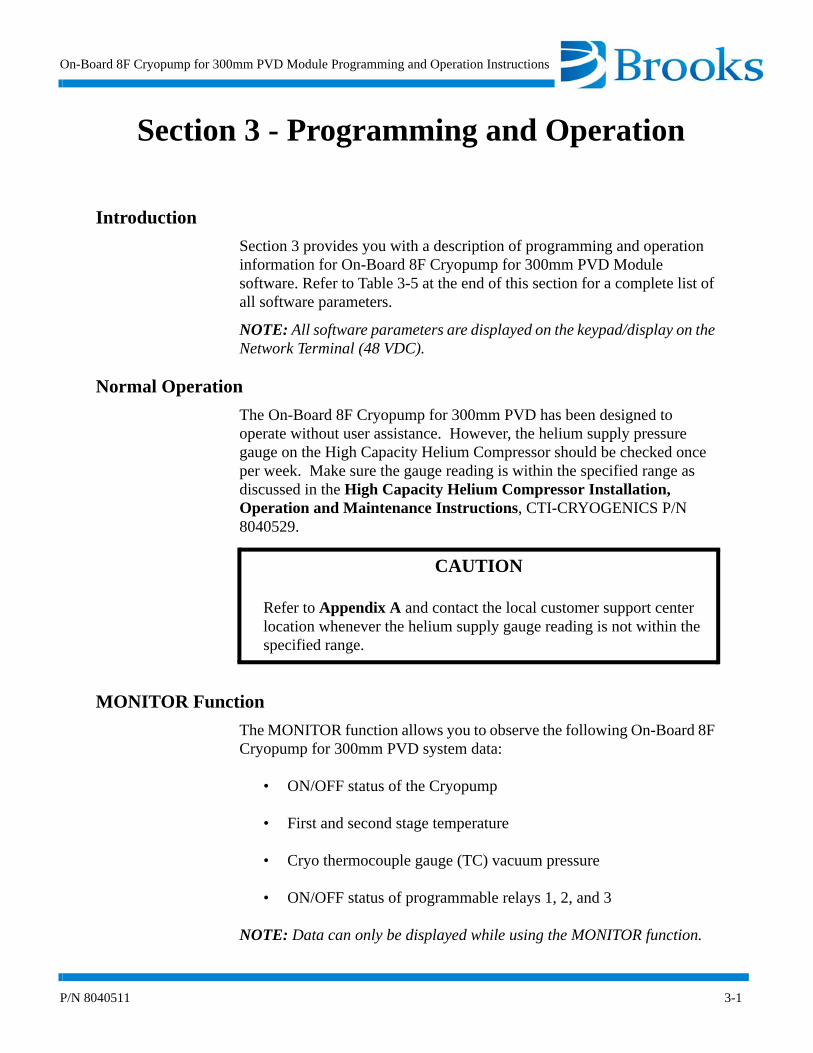
Section 3 provides you with a description of programming and operation information for On-Board 8F Cryopump for 300mm PVD Module software. Refer to Table 3-5 at the end of this section for a complete list of all software parameters.
NOTE: All software parameters are displayed on the keypad/display on the Network Terminal (48 VDC).
Normal Operation
The On-Board 8F Cryopump for 300mm PVD has been designed to operate without user assistance. However, the helium supply pressure gauge on the High Capacity Helium Compressor should be checked once per week. Make sure the gauge reading is within the specified range as discussed in the High Capacity Helium Compressor Installation, Operation and Maintenance Instructions, CTI-CRYOGENICS P/N 8040529.
CAUTION
Refer to Appendix A and contact the local customer support center location whenever the helium supply gauge reading is not within the specified range.
MONITOR Function
The MONITOR function allows you to observe the following On-Board 8F Cryopump for 300mm PVD system data:
• ON/OFF status of the Cryopump
• First and second stage temperature
• Cryo thermocouple gauge (TC) vacuum pressure
• ON/OFF status of programmable relays 1, 2, and 3
NOTE: Data can only be displayed while using the MONITOR function.

Programming and Operation
3-2 P/N 8040511
Data that is displayed using the MONITOR function is useful in determining the operating status of the On-Board 8F Cryopump for 300mm PVD. The flowchart in Figure 3-1 displays all MONITOR software functions.
Figure 3-1: MONITOR Function Flowchart
MONITOR
Cryopump ON/OFF
Second Stage TempCryo TC Gauge Pressure
ON/OFF
Relay 1 ON/OFF
Auto/Manual Control
Relay 2 ON/OFFAuto/Manual Control
HELP
First and Second Stage Temperature
First StageTemp
Second StageTemp Relay 3 ON/OFF
Auto/Manual Control

On-Board 8F Cryopump for 300mm PVD Module Programming and Operation Instructions
P/N 8040511 3-3
Cryopump ON/OFF and Second Stage Temperature
The first parameter within the MONITOR function displays the ON/OFF status and the second stage temperature (degrees Kelvin) as shown in Figure 3-2.
Figure 3-2: ON/OFF Status and Second Stage Temperature
NOTE: Refer to Appendix A and contact the local CTI-CRYOGENICS customer support center if the letters SHO or OPN are displayed.
First and Second Stage Temperature
The second parameter of the MONITOR function displays the first and second stage temperature (degrees Kelvin) as shown in Figure 3-3.
Figure 3-3: First and Second Stage Temperature
Last
Next
Clear
MONITOR
REGEN
SERVICE
CONTROL
RELAYS
HELP
ooON-BOARD®Enter
1 2 3
4 5 6
7 8 9
- 0 .
CRYO ON 12K
Last
Next
Clear
MONITOR
REGEN
SERVICE
CONTROL
RELAYS
HELP
ooON-BOARD®Enter
1 2 3
4 5 6
7 8 9
- 0 .
65K, 12K

Programming and Operation
3-4 P/N 8040511
First Stage Temperature in Kelvin
The third parameter of the MONITOR function displays the first stage temperature (degrees Kelvin) as shown in Figure 3-4.
Figure 3-4: First Stage Temperature
Second Stage Temperature in Kelvin
The fourth parameter of the MONITOR function displays the second stage temperature (degrees Kelvin) as shown in Figure 3-5.
Figure 3-5: Second Stage Temperature
Last
Next
Clear
MONITOR
REGEN
SERVICE
CONTROL
RELAYS
HELP
ooON-BOARD®Enter
1 2 3
4 5 6
7 8 9
- 0 .
1ST STG. = 65K
Last
Next
Clear
MONITOR
REGEN
SERVICE
CONTROL
RELAYS
HELP
ooON-BOARD®Enter
1 2 3
4 5 6
7 8 9
- 0 .
2ND STG. = 12K

On-Board 8F Cryopump for 300mm PVD Module Programming and Operation Instructions
P/N 8040511 3-5
Cryo Thermocouple Gauge Pressure
The fifth parameter of the MONITOR function displays thermocouple gauge pressure (in microns) when turned ON, and indicates when the gauge is turned OFF. Refer to Figure 3-6. The display indicates pressures between 0 - 999 microns.
Figure 3-6: Cryo Thermocouple Gauge Pressure
Relay 1 ON/OFF and Auto/Manual Control
The sixth parameter of the MONITOR function displays the ON/OFF status of Relay 1 and whether Relay 1 is in automatic or manual control. Refer to Figure 3-7.
Figure 3-7: Relay 1 Automatic or Manual Control
Last
Next
Clear
MONITOR
REGEN
SERVICE
CONTROL
RELAYS
HELP
ooON-BOARD®Enter
1 2 3
4 5 6
7 8 9
- 0 .
CRYO TC = 52µ
Last
Next
Clear
MONITOR
REGEN
SERVICE
CONTROL
RELAYS
HELP
ooON-BOARD®Enter
1 2 3
4 5 6
7 8 9
- 0 .
CRYO TC = OFF
Last
Next
Clear
MONITOR
REGEN
SERVICE
CONTROL
RELAYS
HELP
ooON-BOARD®Enter
1 2 3
4 5 6
7 8 9
- 0 .
RLY 1 ON, AUTO
Last
Next
Clear
MONITOR
REGEN
SERVICE
CONTROL
RELAYS
HELP
ooON-BOARD®Enter
1 2 3
4 5 6
7 8 9
- 0 .
RLY 1 ON, MANUAL

Programming and Operation
3-6 P/N 8040511
Relay 2 ON/OFF and Auto/Manual Control
The seventh parameter of the MONITOR function displays the ON/OFF status of Relay 2 and whether Relay 2 is in automatic or manual control. Refer to Figure 3-8.
Figure 3-8: Relay 2 Automatic or Manual Control
Relay 3 ON/OFF and Auto/Manual Control
The eighth parameter of the MONITOR function displays the ON/OFF status of Relay 3 and whether Relay 3 is in automatic or manual control. Refer to Figure 3-9.
Figure 3-9: Relay 2 Automatic or Manual Control
Last
Next
Clear
MONITOR
REGEN
SERVICE
CONTROL
RELAYS
HELP
ooON-BOARD®Enter
1 2 3
4 5 6
7 8 9
- 0 .
RLY 2 ON, AUTO
Last
Next
Clear
MONITOR
REGEN
SERVICE
CONTROL
RELAYS
HELP
ooON-BOARD®Enter
1 2 3
4 5 6
7 8 9
- 0 .
RLY 2 ON, MANUAL
Last
Next
Clear
MONITOR
REGEN
SERVICE
CONTROL
RELAYS
HELP
ooON-BOARD®Enter
1 2 3
4 5 6
7 8 9
- 0 .
RLY 2 ON, AUTO
Last
Next
Clear
MONITOR
REGEN
SERVICE
CONTROL
RELAYS
HELP
ooON-BOARD®Enter
1 2 3
4 5 6
7 8 9
- 0 .
RLY 2 ON, MANUAL

On-Board 8F Cryopump for 300mm PVD Module Programming and Operation Instructions
P/N 8040511 3-7
MONITOR Function Operation
Use the following procedure to observe the MONITOR function parameters of the On-Board 8F Cryopump for 300mm PVD Module.
NOTE: The On-Line HELP function is always available for use during the operation of the MONITOR function. Refer to Section 1 - Basic Information.
1. Press the MONITOR key on the keypad/display. The MONITOR key illuminates, the Cryopump ON/OFF status and the second stage temperature are displayed.
NOTE: Refer to Appendix A and contact the local CTI-CRYOGENICS customer support center if the letters SHO or OPN are displayed.
2. Press the Next key. The first and second stage temperatures are displayed in degrees Kelvin.
3. Press the Next key. The first stage temperature is displayed in degrees Kelvin.
4. Press the Next key. The second stage temperature is displayed in degrees Kelvin.
5. Press the Next key. The Cryopump thermocouple gauge pressure is displayed in microns.
6. Press the Next key. The ON/OFF status of Relay 1 is displayed along with the automatic or manual mode indicator.
7. Press the Next key. The ON/OFF status of Relay 2 is displayed along with the automatic or manual mode indicator.
8. Press the Next key. The ON/OFF status of Relay 3 is displayed along with the automatic or manual mode indicator.

Programming and Operation
3-8 P/N 8040511
Regeneration Function
The REGEN function of the On-Board 8F Cryopump for 300mm PVD Module allows you to initiate a Full or Fast regeneration cycle on your Cryopump. Once initiated, the On-Board Module software automatically sequences your pump through the various phases of the regeneration cycle.
A Full regeneration cycle allows the Cryopump to warm-up to room temperature so that both gases and water vapor collected on the arrays are purged from the pump. Once the contaminates are purged, the Cryopump becomes cold again.
In many cases, there is little water pumped and so it is not necessary to warm the pump to room temperature. If the pump is primarily filled with such gases as argon, nitrogen or hydrogen, then the pump can be regenerated using a Fast Regeneration cycle. A Fast regeneration cycle only warms the Cryopump enough to release the gases condensed on the arrays and trapped within the charcoal. This allows the regeneration cycle to be completed in less time.
One of the key process steps in a Fast regeneration cycle is the removal of the condensed gas by means of the roughing pump. It is important that the condensed gas be removed quickly as the pump warms up, and that a certain minimum base pressure in the Cryopump be achieved quickly. Because of these requirements, it is necessary that Cryopumps that share a common roughing pump be coordinated. That is, the start of regeneration, the opening and closing of the roughing valves and the purge valves on multi-pump On-Board 8F Cryopump for 300mm PVD system must happen at very specific times and in unison. These are coordinated by the Network Terminal (48 VDC). The roughing valves are coordinated by the Network Terminal (48 VDC) for both Fast and Full regeneration cycles although for different reasons.
NOTE: Refer to the Network Terminal (48 VDC) Installation, Operation and Maintenance Instruction manual CTI-CRYOGENICS P/N 8040515G001 for Network Terminal set-up and operating instructions for multi-pump regeneration cycles.
Typically, regeneration is a function that is part of overall periodic maintenance for a Cryopump system: frequency is dependent upon your particular pump application, but the cycle can be manually started at any time.
On-Board 8F Cryopump for 300mm PVD Module Programming and Operation Instructions
P/N 8040511 3-9
The REGEN program incorporates a number of parameters that are preset at the factory, such as RATE-OF- RISE (10u/min.) and default base pressure (50 microns). The On-Board 8F Cryopump for 300mm PVD Module allows you to reprogram the settings, within limits. This is normally done prior to the start of a regeneration cycle. The On-Board 8F Cryopump for 300mm PVD Module also allows you to delay the start and completion of a regeneration cycle. This feature is desirable, for example, when you want to regenerate and start up your Cryopump system during a week-end shutdown. You can reset the REGEN parameters by pressing the REGEN key and stepping through the REGEN menu as shown in Table 3-1.

Programming and Operation
3-10 P/N 8040511
Figure 3-10: Fast Regeneration Cycle Function Flowchart
REGEN
HELP
REGEN Start
Delay Start
Warmup of Cryopump
Warmup Dwell (Purge OFF)
Fast Rough Test
Repurge
Rough out to Base Pressure
Begin Cooldown
Maintain Pump at or Below Base Pressure
REGEN CompletePass
Fail
On-Board 8F Cryopump for 300mm PVD Module Programming and Operation Instructions
P/N 8040511 3-11
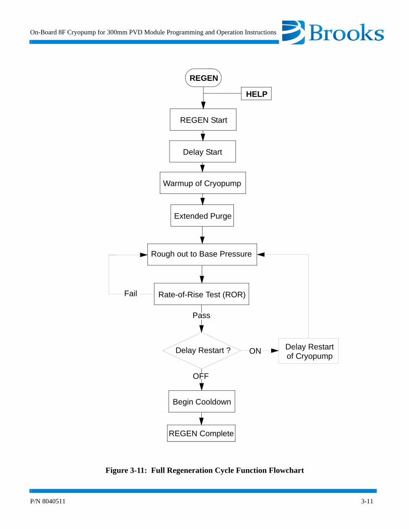
Figure 3-11: Full Regeneration Cycle Function Flowchart
REGEN
HELP
REGEN Start
Delay Start
Warmup of Cryopump
Extended Purge
Rough out to Base Pressure
Begin Cooldown
REGEN Complete
Rate-of-Rise Test (ROR)
Pass
Delay Restart
Fail
Delay Restart ?of Cryopump
ON
OFF
Programming and Operation
3-12 P/N 8040511
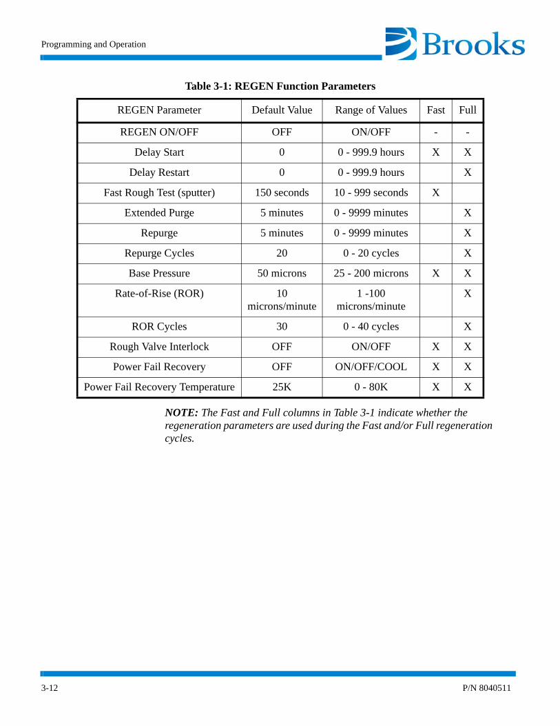
NOTE: The Fast and Full columns in Table 3-1 indicate whether the regeneration parameters are used during the Fast and/or Full regeneration cycles.
Table 3-1: REGEN Function Parameters
REGEN Parameter Default Value Range of Values Fast Full
REGEN ON/OFF OFF ON/OFF - -
Delay Start 0 0 - 999.9 hours X X
Delay Restart 0 0 - 999.9 hours X
Fast Rough Test (sputter) 150 seconds 10 - 999 seconds X
Extended Purge 5 minutes 0 - 9999 minutes X
Repurge 5 minutes 0 - 9999 minutes X
Repurge Cycles 20 0 - 20 cycles X
Base Pressure 50 microns 25 - 200 microns X X
Rate-of-Rise (ROR) 10 microns/minute
1 -100 microns/minute
X
ROR Cycles 30 0 - 40 cycles X
Rough Valve Interlock OFF ON/OFF X X
Power Fail Recovery OFF ON/OFF/COOL X X
Power Fail Recovery Temperature 25K 0 - 80K X X
On-Board 8F Cryopump for 300mm PVD Module Programming and Operation Instructions
P/N 8040511 3-13
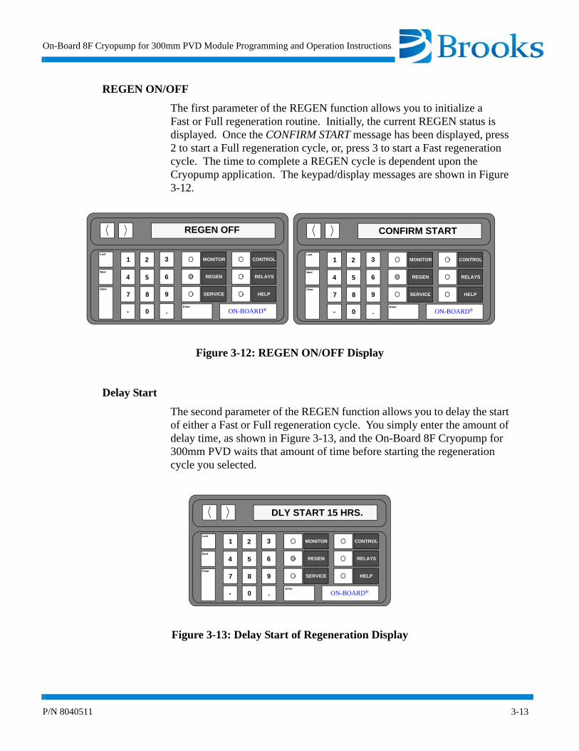
REGEN ON/OFF
The first parameter of the REGEN function allows you to initialize aFast or Full regeneration routine. Initially, the current REGEN status is displayed. Once the CONFIRM START message has been displayed, press 2 to start a Full regeneration cycle, or, press 3 to start a Fast regeneration cycle. The time to complete a REGEN cycle is dependent upon the Cryopump application. The keypad/display messages are shown in Figure 3-12.
Figure 3-12: REGEN ON/OFF Display
Delay Start
The second parameter of the REGEN function allows you to delay the start of either a Fast or Full regeneration cycle. You simply enter the amount of delay time, as shown in Figure 3-13, and the On-Board 8F Cryopump for 300mm PVD waits that amount of time before starting the regeneration cycle you selected.
Figure 3-13: Delay Start of Regeneration Display
Last
Next
Clear
MONITOR
REGEN
SERVICE
CONTROL
RELAYS
HELP
ooON-BOARD®Enter
1 2 3
4 5 6
7 8 9
- 0 .
REGEN OFF
Last
Next
Clear
MONITOR
REGEN
SERVICE
CONTROL
RELAYS
HELP
ooON-BOARD®Enter
1 2 3
4 5 6
7 8 9
- 0 .
CONFIRM START
Last
Next
Clear
MONITOR
REGEN
SERVICE
CONTROL
RELAYS
HELP
ooON-BOARD®Enter
1 2 3
4 5 6
7 8 9
- 0 .
DLY START 15 HRS.
Programming and Operation
3-14 P/N 8040511
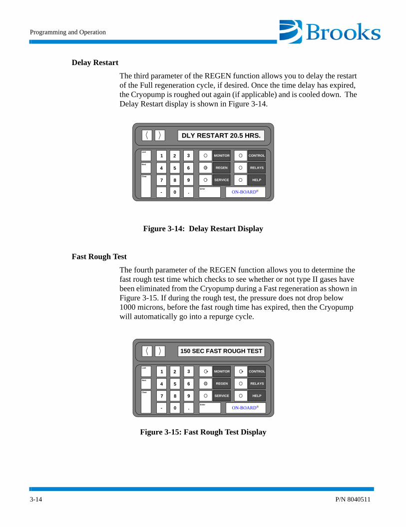
Delay Restart
The third parameter of the REGEN function allows you to delay the restart of the Full regeneration cycle, if desired. Once the time delay has expired, the Cryopump is roughed out again (if applicable) and is cooled down. The Delay Restart display is shown in Figure 3-14.
Figure 3-14: Delay Restart Display
Fast Rough Test
The fourth parameter of the REGEN function allows you to determine the fast rough test time which checks to see whether or not type II gases have been eliminated from the Cryopump during a Fast regeneration as shown in Figure 3-15. If during the rough test, the pressure does not drop below 1000 microns, before the fast rough time has expired, then the Cryopump will automatically go into a repurge cycle.
Figure 3-15: Fast Rough Test Display
Last
Next
Clear
MONITOR
REGEN
SERVICE
CONTROL
RELAYS
HELP
ooON-BOARD®Enter
1 2 3
4 5 6
7 8 9
- 0 .
DLY RESTART 20.5 HRS.
Last
Next
Clear
MONITOR
REGEN
SERVICE
CONTROL
RELAYS
HELP
ooON-BOARD®Enter
1 2 3
4 5 6
7 8 9
- 0 .
150 SEC FAST ROUGH TEST

On-Board 8F Cryopump for 300mm PVD Module Programming and Operation Instructions
P/N 8040511 3-15
Extended Purge
The fifth parameter of the REGEN function allows you to extend the purge time during Full regeneration to ensure the Cryopump has been purged of all contaminants. The extended purge time screen display is shown in Figure 3-16.
Figure 3-16: Extended Purge Display
Repurge
The sixth parameter of the REGEN function allows you to establish the repurge time in the event of repurge as shown in Figure 3-17. A repurge occurs during Full regeneration when the roughing pressure fails to decrease at a rate of at least 2% per minute.
Figure 3-17: Repurge Display
Last
Next
Clear
MONITOR
REGEN
SERVICE
CONTROL
RELAYS
HELP
ooON-BOARD®Enter
1 2 3
4 5 6
7 8 9
- 0 .
EXTD PURGE 10M
Last
Next
Clear
MONITOR
REGEN
SERVICE
CONTROL
RELAYS
HELP
ooON-BOARD®Enter
1 2 3
4 5 6
7 8 9
- 0 .
10 MIN REPURGE
Programming and Operation
3-16 P/N 8040511
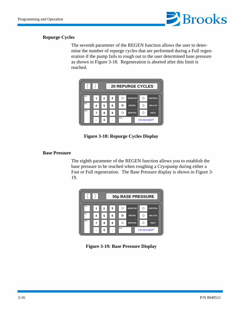
Repurge Cycles
The seventh parameter of the REGEN function allows the user to deter-mine the number of repurge cycles that are performed during a Full regen-eration if the pump fails to rough out to the user determined base pressure as shown in Figure 3-18. Regeneration is aborted after this limit is reached.
Figure 3-18: Repurge Cycles Display
Base Pressure
The eighth parameter of the REGEN function allows you to establish the base pressure to be reached when roughing a Cryopump during either a Fast or Full regeneration. The Base Pressure display is shown in Figure 3-19.
Figure 3-19: Base Pressure Display
Last
Next
Clear
MONITOR
REGEN
SERVICE
CONTROL
RELAYS
HELP
ooON-BOARD®Enter
1 2 3
4 5 6
7 8 9
- 0 .
20 REPURGE CYCLES
Last
Next
Clear
MONITOR
REGEN
SERVICE
CONTROL
RELAYS
HELP
ooON-BOARD®Enter
1 2 3
4 5 6
7 8 9
- 0 .
50µ BASE PRESSURE

On-Board 8F Cryopump for 300mm PVD Module Programming and Operation Instructions
P/N 8040511 3-17
Rate-of-Rise
The ninth parameter of the REGEN function allows you to establish the micron/minute rate in which the Rate-of-Rise (ROR) test is performed during a Full regeneration. The ROR display is shown in Figure 3-20.
Figure 3-20: Rate-of-Rise Display
ROR Cycles
The tenth parameter of the REGEN function allows you to establish the number of times the ROR test can be performed before the Full regeneration cycle is aborted. The ROR Cycles display is shown in Figure 3-21.
Figure 3-21: ROR Cycles Display
Last
Next
Clear
MONITOR
REGEN
SERVICE
CONTROL
RELAYS
HELP
ooON-BOARD®Enter
1 2 3
4 5 6
7 8 9
- 0 .
10µ/MIN ROR
Last
Next
Clear
MONITOR
REGEN
SERVICE
CONTROL
RELAYS
HELP
ooON-BOARD®Enter
1 2 3
4 5 6
7 8 9
- 0 .
20 ROR CYCLES

Programming and Operation
3-18 P/N 8040511
Rough Valve Interlock
The eleventh parameter of the REGEN function allows the roughing valve to operate independent of the rough valve grouping when Rough Valve Interlock is set to OFF (0). The Rough Valve Interlock display is shown in Figure 3-22. When the rough valve interlock is ON, the rough valve will open during regeneration when permission is received from the Network Terminal.
Figure 3-22: Rough Valve Interlock Display
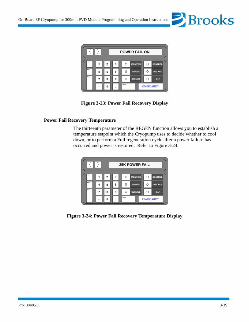
Power Fail Recovery
The twelfth parameter of the REGEN function allows the Cryopump to automatically perform a REGEN cycle, or to cool down if below the power failure recovery temperature, after a power failure has occurred, as shown in Figure 3-23. There are three settings available to you:
• 0 - Power Fail OFF
• 1 - Power Fail ON
• 2 - Power Fail Cool
NOTE: If Power Fail Cool is selected, and the power failure occurs while the Cryopump is ON, the Cryopump will only cool down if it is below the power fail recovery temperature setpoint. If the Cryopump temperature is above the setpoint, the Cryopump will remain OFF.
Last
Next
Clear
MONITOR
REGEN
SERVICE
CONTROL
RELAYS
HELP
ooON-BOARD®Enter
1 2 3
4 5 6
7 8 9
- 0 .
0 ROUGH VALVE INTERLOCK
On-Board 8F Cryopump for 300mm PVD Module Programming and Operation Instructions
P/N 8040511 3-19
Figure 3-23: Power Fail Recovery Display
Power Fail Recovery Temperature
The thirteenth parameter of the REGEN function allows you to establish a temperature setpoint which the Cryopump uses to decide whether to cool down, or to perform a Full regeneration cycle after a power failure has occurred and power is restored. Refer to Figure 3-24.
Figure 3-24: Power Fail Recovery Temperature Display
Last
Next
Clear
MONITOR
REGEN
SERVICE
CONTROL
RELAYS
HELP
ooON-BOARD®Enter
1 2 3
4 5 6
7 8 9
- 0 .
POWER FAIL ON
Last
Next
Clear
MONITOR
REGEN
SERVICE
CONTROL
RELAYS
HELP
ooON-BOARD®Enter
1 2 3
4 5 6
7 8 9
- 0 .
25K POWER FAIL

Programming and Operation
3-20 P/N 8040511
REGEN Function Programming
Use the following procedures to program individual REGEN function parameters of the On-Board 8F Cryopump for 300mm PVD Module.
Initiate REGEN
1. Press the REGEN key on the keypad/display. The current REGEN status is displayed.
2. Press 1 to initiate a regeneration cycle.
3. Press 2 to confirm the start of a Full regeneration cycle.
4. Press 3 to confirm the start of a Fast regeneration cycle.
Abort REGEN
1. Press the REGEN key on the keypad/display. The current REGEN status is displayed.
2. Press 0 to abort a regeneration cycle.
3. Press 2 to confirm the end of a regeneration cycle.
Delay Start
1. Press the REGEN key on the keypad/display. The current REGEN status is displayed.
2. Press the Next key. The current delay start time value is displayed in hours.
3. Press the Enter key. The current value is underlined and ready to accept a new value.
4. Press the numeral keys for the desired delay time. For example: 1, 5 for 1.5, or 1, 5, and 0 for 15.0. The range of values is 0 - 999.9 hours.
NOTE: The Clear key may be pressed if incorrect data has been entered. The On-Board Module software allows you to enter the new value.
5. Press the Enter key. Delay start programming is complete.
6. Press the MONITOR key. The On-Board Module software will monitor system operation.
On-Board 8F Cryopump for 300mm PVD Module Programming and Operation Instructions
P/N 8040511 3-21
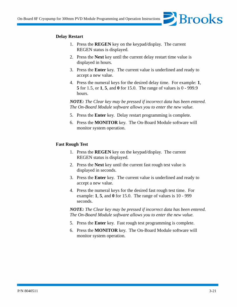
Delay Restart
1. Press the REGEN key on the keypad/display. The current REGEN status is displayed.
2. Press the Next key until the current delay restart time value is displayed in hours.
3. Press the Enter key. The current value is underlined and ready to accept a new value.
4. Press the numeral keys for the desired delay time. For example: 1, 5 for 1.5, or 1, 5, and 0 for 15.0. The range of values is 0 - 999.9 hours.
NOTE: The Clear key may be pressed if incorrect data has been entered. The On-Board Module software allows you to enter the new value.
5. Press the Enter key. Delay restart programming is complete.
6. Press the MONITOR key. The On-Board Module software will monitor system operation.
Fast Rough Test
1. Press the REGEN key on the keypad/display. The current REGEN status is displayed.
2. Press the Next key until the current fast rough test value is displayed in seconds.
3. Press the Enter key. The current value is underlined and ready to accept a new value.
4. Press the numeral keys for the desired fast rough test time. For example: 1, 5, and 0 for 15.0. The range of values is 10 - 999 seconds.
NOTE: The Clear key may be pressed if incorrect data has been entered. The On-Board Module software allows you to enter the new value.
5. Press the Enter key. Fast rough test programming is complete.
6. Press the MONITOR key. The On-Board Module software will monitor system operation.

Programming and Operation
3-22 P/N 8040511
Extended Purge
1. Press the REGEN key on the keypad/display. The current REGEN status is displayed.
2. Press the Next key until the extended purge value is displayed in minutes.
3. Press the Enter key. The current value is underlined and ready to accept a new value.
4. Press the numeral keys for the desired extended purge time. For example: 1, 5, and 0 for 15.0. The range of values is 0 - 9999 minutes.
NOTE: The Clear key may be pressed if incorrect data has been entered. The On-Board Module software allows you to enter the new value.
5. Press the Enter key. Extended purge programming is complete.
6. Press the MONITOR key. The On-Board Module software will monitor system operation.
Repurge
1. Press the REGEN key on the keypad/display. The current REGEN status is displayed.
2. Press the Next key until the repurge value is displayed in minutes.
3. Press the Enter key. The current value is underlined and ready to accept a new value.
4. Press the numeral keys for the desired repurge time. For example: 1, 5, and 0 for 15.0. The range of values is 0 - 9999 minutes.
NOTE: The Clear key may be pressed if incorrect data has been entered. The On-Board Module software allows you to enter the new value.
5. Press the Enter key. Repurge programming is complete.
6. Press the MONITOR key. The On-Board Module software will monitor system operation.
Repurge Cycles
1. Press the REGEN key on the keypad/display. The current REGEN status is displayed.
2. Press the Next key until the current number of repurge cycles is displayed.

On-Board 8F Cryopump for 300mm PVD Module Programming and Operation Instructions
P/N 8040511 3-23
3. Press the Enter key. The current value is underlined and ready to accept a new value.
4. Press the numeral keys for the desired number of repurge cycles. For example: 1, 5 for 15. The range of values is 0 - 20 cycles.
NOTE: The Clear key may be pressed if incorrect data has been entered. The On-Board Module software allows you to enter the new value.
5. Press the Enter key. Repurge cycles programming is complete.
6. Press the MONITOR key. The On-Board Module software will monitor system operation.
Base Pressure
1. Press the REGEN key on the keypad/display. The current REGEN status is displayed.
2. Press the Next key until the current base pressure value is displayed in microns.
3. Press the Enter key. The current value is underlined and ready to accept a new value.
4. Press the numeral keys for the desired base pressure. For example: 3, 5, for 35. The range of values is 25 - 200 microns.
NOTE: The Clear key may be pressed if incorrect data has been entered. The On-Board Module software allows you to enter the new value.
5. Press the Enter key. Base pressure programming is complete.
6. Press the MONITOR key. The On-Board Module software will monitor system operation.
Rate-of-Rise (ROR)
1. Press the REGEN key on the keypad/display. The current REGEN status is displayed.
2. Press the Next key until the current ROR value is displayed.
3. Press the Enter key. The current value is underlined and ready to accept a new value.
4. Press the numeral keys for the desired ROR value. For example: 1, 5 for 15. The range of values is 0 - 100 microns/minute.
NOTE: The Clear key may be pressed if incorrect data has been entered. The On-Board Module software allows you to enter the new value.
5. Press the Enter key. ROR programming is complete.

Programming and Operation
3-24 P/N 8040511
6. Press the MONITOR key. The On-Board Module software will monitor system operation.
Rate-of-Rise (ROR) Cycles
1. Press the REGEN key on the keypad/display. The current REGEN status is displayed.
2. Press the Next key until the current value for the ROR cycles is displayed.
3. Press the Enter key. The current value is underlined and ready to accept a new value.
4. Press the numeral keys for the desired number of cycles. For exam-ple: 1, 5, for 15. The range of values is 0 - 40 cycles.
NOTE: The Clear key may be pressed if incorrect data has been entered. The On-Board Module software allows you to enter the new value.
5. Press the Enter key. ROR cycle programming is complete.
6. Press the MONITOR key. The On-Board Module software will monitor system operation.
Rough Valve Interlock
1. Press the REGEN key on the keypad/display. The current REGEN status is displayed.
2. Press the Next key until the current state for rough valve interlock is displayed.
NOTE: The rough valve interlock must be OFF when a Cryopump is not being operated within a rough valve group. Otherwise, the rough valve will never open and the Cryopump will remain in the rough share wait mode.
3. Press the Enter key. The current value is underlined and ready to accept a new value.
4. Press the numeral keys to turn the rough valve interlock ON or OFF. The range of values is 1 (ON) or 0 (OFF).
5. Press the Enter key. Rough valve interlock programming is com-plete.
6. Press the MONITOR key. The On-Board Module software will monitor system operation.

On-Board 8F Cryopump for 300mm PVD Module Programming and Operation Instructions
P/N 8040511 3-25
Power Failure Recovery
1. Press the REGEN key on the keypad/display. The current REGEN status is displayed.
2. Press the Next key until the current mode for power failure recov-ery is displayed.
3. Press the desired numeral key to set power failure recovery to the desired mode. The range of values is 0 (OFF), 1 (ON), or 2 (Cool).
4. Press the MONITOR key. The On-Board Module software will monitor system operation.
NOTE: The Power Failure option only allows for a Full regeneration cycle.
Power Failure Recovery Temperature
1. Press the REGEN key on the keypad/display. The current REGEN status is displayed.
2. Press the Next key until the current power failure recovery temper-ature is displayed.
3. Press the Enter key. The current value is underlined and ready to accept a new value.
4. Press the numeral keys for the desired recovery temperature. For example: 2, and 5 for 25K. The range of values is 10 - 80K.
NOTE: The Clear key may be pressed if incorrect data has been entered. The On-Board Module software allows you to enter the new value.
5. Press the Enter key. Power failure recovery temperature program-ming is complete.
6. Press the MONITOR key. The On-Board Module software will monitor system operation.
NOTE: In the event of a power failure, if the Cryopump is ON and Power Failure Recovery is ON, and the Cryopump warms up to a temperature higher than the temperature setpoint, the Cryopump will be automatically regenerated. The display will read POWER FAILURE - REGENERATION.
NOTE: If a Delay Start or Delay Restart has been programmed, these times will be ignored for regeneration initiated due to a power failure.

Programming and Operation
3-26 P/N 8040511
NOTE: If the Cryopump temperature stays lower than the setpoint, the Cryopump is restarted. The Cryopump has 30 minutes for the second stage temperature to cool below 17K. If this temperature is not achieved, the display will read POWER FAILURE - CHECK CRYO TEMP.
NOTE: If the Cryopump is in regeneration and is cooling, the cooling will continue if the thermocouple pressure is below 100µ. If the Cryopump is in any other phase of regeneration, or if the thermocouple pressure is above 100µ, regeneration will start over again. If cooldown continues, the display will read POWER FAILURE - COOLDOWN.
Performing a Fast or Full Regeneration Cycle
Make sure you program the REGEN function parameters to your desired values before attempting to perform a Fast or Full regeneration cycle.
Fast Regeneration Cycle
1. Press the REGEN key on the keypad/display. The current REGEN status is displayed.
2. Press 1 to initiate a regeneration cycle.
3. Press 3 to confirm the start of a Fast regeneration cycle. A Fast regeneration cycle has been initiated.
The On-Board 8F Cryopump for 300mm PVD Module performs a Fast regeneration cycle according to the REGEN parameters you have programmed. Refer to Figure 3-10 for more information.
Full Regeneration Cycle
1. Press the REGEN key on the keypad/display. The current REGEN status is displayed.
2. Press 1 to initiate a regeneration cycle.
3. Press 2 to confirm the start of a Full regeneration cycle. A Full regeneration cycle has been initiated.
The On-Board 8F Cryopump for 300mm PVD Module performs a Full regeneration cycle according to the REGEN parameters you have programmed. Refer to Figure 3-11 for more information.

On-Board 8F Cryopump for 300mm PVD Module Programming and Operation Instructions
P/N 8040511 3-27
REGEN Cycle Examples
The flowcharts in Figures 3-25 and 3-26 provide you with examples of the typical REGEN cycle for On-Board 8F Cryopump for 300mm PVD Module.
NOTE: The values in these examples are for discussion purposes only.
Figure 3-25: Full Regeneration Cycle Example
START
Press REGEN
Press 1 To Start
REGEN OFF
CONFIRM START
PRESS 2
Press 2 To Confirm Start
The On-Board 8F Cryopump for 300mm PVD Module is ready to start a REGEN cycle.
Regeneration is ready to start.
DLY START 15.5 HRS.A DELAY START has been programmed. The On-Board 8F Cryopump for 300mm PVD Module will wait 15.5 hours before the REGEN cycle begins.
WARM-UP 125K/310K
EXTD PURGE 5M
The Cryopump shuts OFF, the purge valve opens, and purging begins. The display shows second stage temperature (125K) and the target temperature (310K). Heaters are turned ON and the arrays are warmed up to 310K.
When the second stage reaches 310K, the purge gas stays ON for (5M) additional minutes (which is the extended purge). EXTENDED PURGE time purges water or other contaminants from the Cryopump during a REGEN cycle. At the end of the extended purge, the purge valve is closed and the rough valve is opened automatically.
Continued on page 3-28
Confirms the start of full regeneration.

Programming and Operation
3-28 P/N 8040511
Figure 3-25: Full Regeneration Cycle Example (continued)
From page 3-27
Displays the current pressure (125µ) and the base pressure to be achieved (50µ). The Cryopump is roughed out until the base pressure is reached.
The Cryopump is roughed out again until the base pressure is reached.
The following events occur:
- Cryopump TC reaches programmed base pressure of 50µ
- Rough valve closes and the On-Board 8F Cryopump for 300mm PVD Module waits 15 seconds to stabilize
- On-Board 8F Cryopump for 300mm PVD Module measures TC pressure and takes second reading in 30 seconds
- On-Board 8F Cryopump for 300mm PVD Module calculates ROR pressure increase in µ/minute
- If ROR is less than programmed value, the ROR test passes
- If ROR is more than programmed value, the ROR test is repeated
The display indicates the number of ROR test cycles (3), current ROR
value (124µ/10µ), and the programmed ROR value (10µ/m).
If ROR test is repeated:
- Rough valve opens
- Cryopump is roughed out again to base pressure
- ROR test is repeated
ROR 3 124µ/10µ
Continued on page 3-29
ROUGH 125µ/50µ
REPURGE #1 2M
If the pressure does not reduce at a reasonable rate during the rough out phase, the On-Board 8F Cryopump for 300mm PVD Module will automatically repurge the Cryopump for the programmed REPURGE time. The display indicates that this is the first purge cycle (#1) and that there are two minutes (2M) remaining in this cycle.

On-Board 8F Cryopump for 300mm PVD Module Programming and Operation Instructions
P/N 8040511 3-29
Figure 3-25: Full Regeneration Cycle Example (continued)
From page 3-28
If a DELAY RESTART time has been programmed, the following events occur:
- The On-Board 8F Cryopump for 300mm PVD Module backfills the Cryopump with purge gas and waits the programmed DELAY RESTART time
- The Cryopump is roughed out
- The ROR test is repeated
- The Cryopump cools down
REGEN COMPLETE
DLY RESTART 20.5 HRS.
COOLDOWN 235K/17K
STOP REGEN?
The Cryopump turns ON after successful completion of the ROR test. During cooldown mode, the display indicates real time temperature(235K) and the base temperature (17K).
When the Cryopump reaches 17K, the REGEN cycle is complete and the temperature control activates the programmed first stage tempera-ture control setpoint.
END
Programming and Operation
3-30 P/N 8040511
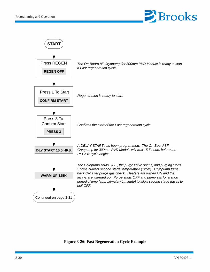
Figure 3-26: Fast Regeneration Cycle Example
START
Press REGEN
Press 1 To Start
REGEN OFF
CONFIRM START
PRESS 3
Press 3 To Confirm Start
The On-Board 8F Cryopump for 300mm PVD Module is ready to start a Fast regeneration cycle.
Regeneration is ready to start.
DLY START 15.5 HRS.A DELAY START has been programmed. The On-Board 8F Cryopump for 300mm PVD Module will wait 15.5 hours before the REGEN cycle begins.
WARM-UP 125K
The Cryopump shuts OFF , the purge valve opens, and purging starts. Shows current second stage temperature (125K). Cryopump turns back ON after purge gas check. Heaters are turned ON and the arrays are warmed up. Purge shuts OFF and pump sits for a short period of time (approximately 1 minute) to allow second stage gases to boil OFF.
Continued on page 3-31
Confirms the start of the Fast regeneration cycle.
On-Board 8F Cryopump for 300mm PVD Module Programming and Operation Instructions
P/N 8040511 3-31
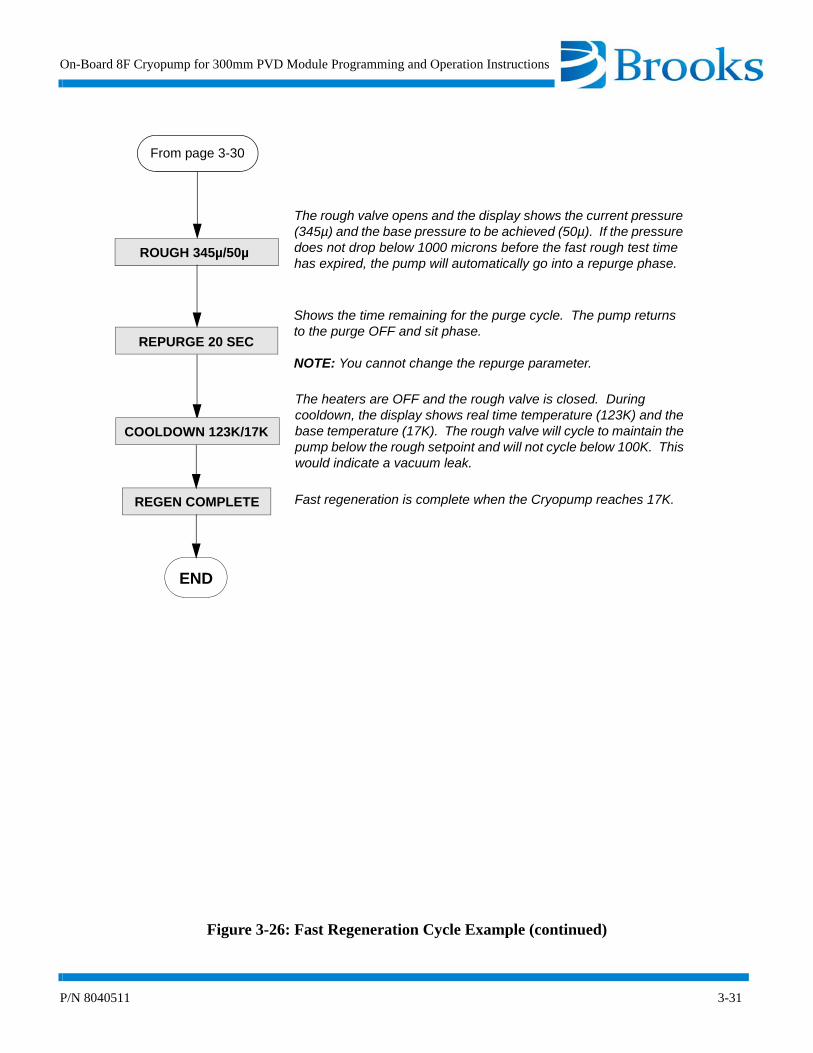
Figure 3-26: Fast Regeneration Cycle Example (continued)
From page 3-30
ROUGH 345µ/50µ
REPURGE 20 SEC
COOLDOWN 123K/17K
END
REGEN COMPLETE
The rough valve opens and the display shows the current pressure (345µ) and the base pressure to be achieved (50µ). If the pressure does not drop below 1000 microns before the fast rough test time has expired, the pump will automatically go into a repurge phase.
Shows the time remaining for the purge cycle. The pump returns to the purge OFF and sit phase.
NOTE: You cannot change the repurge parameter.
The heaters are OFF and the rough valve is closed. During cooldown, the display shows real time temperature (123K) and the base temperature (17K). The rough valve will cycle to maintain the pump below the rough setpoint and will not cycle below 100K. This would indicate a vacuum leak.
Fast regeneration is complete when the Cryopump reaches 17K.

Programming and Operation
3-32 P/N 8040511
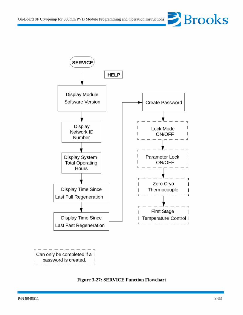
SERVICE Function
The On-Board 8F Cryopump for 300mm PVD Module SERVICE function allows you to access Cryopump identification information, elapsed pump times, and establish password protection as shown in Figure 3-27. The default and range of SERVICE function parameters are listed in Table 3-2. An explanation of each parameter is provided on the following pages.
On-Board 8F Cryopump for 300mm PVD Module Programming and Operation Instructions
P/N 8040511 3-33
Figure 3-27: SERVICE Function Flowchart
SERVICE
HELP
Display Time Since
Last Full Regeneration
Display Module
Software Version
Display SystemTotal Operating
Hours
Create Password
Lock ModeON/OFF
Parameter LockON/OFF
Zero CryoThermocouple
First Stage
ControlTemperature
DisplayNetwork ID
Number
Can only be completed if a password is created.
Display Time Since
Last Fast Regeneration

Programming and Operation
3-34 P/N 8040511
Serial Number and Software Version
The first parameter of the SERVICE function allows you to display the current software version (P information) as shown in Figure 3-28.
The software version number identifies the software which is running in the On-Board 8F Cryopump for 300mm PVD Module.
NOTE: Press the > key to display the entire software version number.
Figure 3-28: Serial Number and Software Version Display
Table 3-2: SERVICE Function Parameters
SERVICE Parameter Default Value Range of Values
Serial Number/Software Version - -
Net ID 0 0 - 9
Elapsed Pump Time - Hours
Time Since Last Full Regeneration - Hours
Time Since Last Fast Regeneration - Hours
Password 0 0 - 32,767
Lock Mode OFF 1 (ON)/ 0 (OFF)
Parameter Lock OFF 1 (ON)/ 0 (OFF)
Zero Cryopump Thermocouple - -
First Stage Temperature ON 1 (ON)/ 0 (OFF)
Last
Next
Clear
MONITOR
REGEN
SERVICE
CONTROL
RELAYS
HELP
ooON-BOARD®Enter
1 2 3
4 5 6
7 8 9
- 0 .
PG2.46
On-Board 8F Cryopump for 300mm PVD Module Programming and Operation Instructions
P/N 8040511 3-35
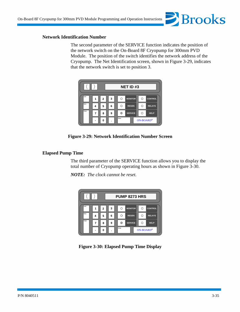
Network Identification Number
The second parameter of the SERVICE function indicates the position of the network switch on the On-Board 8F Cryopump for 300mm PVD Module. The position of the switch identifies the network address of the Cryopump. The Net Identification screen, shown in Figure 3-29, indicates that the network switch is set to position 3.
Figure 3-29: Network Identification Number Screen
Elapsed Pump Time
The third parameter of the SERVICE function allows you to display the total number of Cryopump operating hours as shown in Figure 3-30.
NOTE: The clock cannot be reset.
Figure 3-30: Elapsed Pump Time Display
Last
Next
Clear
MONITOR
REGEN
SERVICE
CONTROL
RELAYS
HELP
ooON-BOARD®Enter
1 2 3
4 5 6
7 8 9
- 0 .
NET ID #3
Last
Next
Clear
MONITOR
REGEN
SERVICE
CONTROL
RELAYS
HELP
ooON-BOARD®Enter
1 2 3
4 5 6
7 8 9
- 0 .
PUMP 8273 HRS

Programming and Operation
3-36 P/N 8040511
Time Since Last Full Regeneration
The fourth parameter of the SERVICE function allows you to display the total number of hours since the last Full regeneration cycle was performed as shown in Figure 3-31. The clock is automatically reset to zero upon the completion of the last Full regeneration cycle.
Figure 3-31: Time Since Last Full Regeneration Display
Time Since Last Fast Regeneration
The fifth parameter of the SERVICE function allows you to display the total number of hours since the last Fast regeneration cycle was performed as shown in Figure 3-32. The clock is automatically reset to zero upon the completion of the last Fast regeneration cycle.
Figure 3-32: Time Since Last Fast Regeneration Display
Last
Next
Clear
MONITOR
REGEN
SERVICE
CONTROL
RELAYS
HELP
ooON-BOARD®Enter
1 2 3
4 5 6
7 8 9
- 0 .
FULL RGN 42 HRS
Last
Next
Clear
MONITOR
REGEN
SERVICE
CONTROL
RELAYS
HELP
ooON-BOARD®Enter
1 2 3
4 5 6
7 8 9
- 0 .
FAST RGN 5 HRS

On-Board 8F Cryopump for 300mm PVD Module Programming and Operation Instructions
P/N 8040511 3-37
Password
The sixth parameter of the SERVICE function allows you to create or display a password. A password allows a level of system security to prevent unauthorized users from accessing SERVICE functions. The password display screen is shown in Figure 3-33.
NOTE: Refer to Appendix A and contact the local customer support center if the password is forgotten. A master password can be used to clear the original password.
Figure 3-33: Password Screen Display
Lock Mode
The seventh parameter of the SERVICE function prevents an unauthorized user from accessing the REGEN, CONTROL, or RELAYS functions when lock mode is ON. A LOCKED OUT message is displayed when the REGEN, CONTROL, or RELAYS keys are pressed. The Lock Mode OFF screen is shown in Figure 3-34.
Figure 3-34: Lock Mode OFF Display
Last
Next
Clear
MONITOR
REGEN
SERVICE
CONTROL
RELAYS
HELP
ooON-BOARD®Enter
1 2 3
4 5 6
7 8 9
- 0 .
PASSWORD ?
Last
Next
Clear
MONITOR
REGEN
SERVICE
CONTROL
RELAYS
HELP
ooON-BOARD®Enter
1 2 3
4 5 6
7 8 9
- 0 .
LOCK MODE OFF

Programming and Operation
3-38 P/N 8040511
Parameter Lock
The eighth parameter of the SERVICE function prevents an unauthorized user from accessing all programmable REGEN parameters and relay setpoints. When an attempt is made to change a programmable setpoint with Parameter Lock ON, the CHANGES LOCKED message is displayed as shown in Figure 3-35. All parameters which can be turned ON or OFF, including Regeneration, are still accessible with Parameter Lock turned ON.
Figure 3-35: Parameter Lock ON Display
Zero Cryo Thermocouple
The ninth parameter of the SERVICE function, as shown in Figure 3-36, resets the cryo thermocouple gauge to zero. The cryo thermocouple gauge reading is displayed until the gauge is set to zero.
NOTE: The cryo thermocouple gauge must be turned ON and under a vacuum of less than 10-4 torr (less than 1 micron) before this parameter can be used. Any attempt to zero the gauge at a pressure above 30 microns, or when the gauge is turned OFF, results in a calibration failure.
Figure 3-36: Zero Cryo Thermocouple Gauge Display
Last
Next
Clear
MONITOR
REGEN
SERVICE
CONTROL
RELAYS
HELP
ooON-BOARD®Enter
1 2 3
4 5 6
7 8 9
- 0 .
PARAM LOCK OFF
Last
Next
Clear
MONITOR
REGEN
SERVICE
CONTROL
RELAYS
HELP
ooON-BOARD®Enter
1 2 3
4 5 6
7 8 9
- 0 .
ZERO CRYO TC

On-Board 8F Cryopump for 300mm PVD Module Programming and Operation Instructions
P/N 8040511 3-39
First Stage Temperature Control
The tenth and final parameter of the SERVICE function allows the first stage temperature control of the Cryopump to be turned ON or OFF. The first stage temperature setting is displayed as shown in Figure 3-37.
Figure 3-37: First Stage Temperature Control Display
SERVICE Function Operation
Use the following procedures to operate the SERVICE function parameters of the On-Board 8F Cryopump for 300mm PVD Module.
Software Version
1. Press the SERVICE key on the keypad/display. The serial number and software version information is displayed.
2. Press the MONITOR key. The On-Board Module software will monitor system operation.
Net Identification
1. Press the SERVICE key on the keypad/display. The software version information is displayed.
2. Press the Next key. The Net ID number is displayed.
3. Press the MONITOR key. The On-Board Module software will monitor system operation.
Last
Next
Clear
MONITOR
REGEN
SERVICE
CONTROL
RELAYS
HELP
ooON-BOARD®Enter
1 2 3
4 5 6
7 8 9
- 0 .
1ST TMP CTL ON
Programming and Operation
3-40 P/N 8040511
Elapsed Pump Time
1. Press the SERVICE key on the keypad/display. The software version information is displayed.
2. Press the Next key until the Pump Hours are displayed.
3. Press the MONITOR key. The On-Board Module software will monitor system operation.
Time Since Last Full Regeneration
1. Press the SERVICE key on the keypad/display. The software version information is displayed.
2. Press the Next key until the Full RGN Hours are displayed.
3. Press the MONITOR key. The On-Board Module software will monitor system operation.
Time Since Last Fast Regeneration
1. Press the SERVICE key on the keypad/display. The software version information is displayed.
2. Press the Next key until the Fast RGN Hours are displayed.
3. Press the MONITOR key. The On-Board Module software will monitor system operation.
Password
1. Press the SERVICE key on the keypad/display. The software version information is displayed.
2. Press the Next key until the Password prompt is displayed.
3. Press the Enter key. 0 = Password is displayed.
4. Press the Enter key again. The current value is underlined and ready to accept a new value.
5. Press the numeral keys for the desired password. The range of values is 0 - 32767.
6. Press the Enter button.
7. Press the MONITOR key. The On-Board Module software will monitor system operation.
NOTE: Refer to Appendix A and contact the local customer support center if the password is forgotten. A master password can be used to access the original password.
On-Board 8F Cryopump for 300mm PVD Module Programming and Operation Instructions
P/N 8040511 3-41
Lock Mode
NOTE: The Lock Mode parameter cannot be accessed unless a password has been entered.
1. Press the SERVICE key on the keypad/display. The software version information is displayed.
2. Press the Next key until the Password? prompt is displayed.
3. Enter the password and press Enter.
4. Press the Next key until the current status of Lock Mode is dis-played.
5. Press 1 to enable or press 0 to disable lock mode.
6. Press the MONITOR key. The On-Board Module software will monitor system operation.
Parameter Lock
NOTE: The Parameter Lock parameter cannot be accessed unless a password has been entered.
1. Press the SERVICE key on the keypad/display. The software version information is displayed.
2. Press the Next key until the Password? prompt is displayed.
3. Enter the password and press Enter.
4. Press the Next key until the current status of Param Lock is dis-played.
5. Press 1 to enable or press 0 to disable parameter lock mode.
6. Press the MONITOR key. The On-Board Module software will monitor system operation.

Programming and Operation
3-42 P/N 8040511
Zero Cryo Thermocouple
NOTE: The Zero Cryo Thermocouple parameter cannot be accessed unless a password has been entered.
NOTE: The cryo thermocouple gauge must be turned ON and under a vacuum of less than 10-4 torr (less than 1 micron) before this procedure can be used. Any attempt to zero the gauge at a pressure above 30 microns, or when the gauge is turned OFF, results in a calibration failure.
1. Press the SERVICE key on the keypad/display. The software version information is displayed.
2. Press the Next key until the Password? prompt is displayed.
3. Enter the password and press Enter.
4. Press the Next key until Zero Cryo TC is displayed.
5. Press the Enter key. The cryo thermocouple pressure is displayed until zero is reached. After approximately 1 minute, Complete will be displayed.
6. Press the MONITOR key. The On-Board Module software will monitor system operation.
First Stage Temperature Control
NOTE: The First Stage Temperature Control parameter cannot be accessed unless a password has been entered.
1. Press the SERVICE key on the keypad/display. The software version information is displayed.
2. Press the Next key until the Password? prompt is displayed.
3. Enter the password and press Enter.
4. Press the Next key until 1ST TMP CTL is displayed.
5. Press the Enter key. Press 1 to turn on the first stage temperature control. Press 0 to turn it OFF.
6. Press the Enter button.
7. Press the MONITOR key. The On-Board Module software will monitor system operation.

On-Board 8F Cryopump for 300mm PVD Module Programming and Operation Instructions
P/N 8040511 3-43
CONTROL Function
The CONTROL function within the On-Board 8F Cryopump for 300mm PVD Module allows you to turn the Cryopump, plus selected gauges, valves, and relays ON or OFF. These functions can be used during manual regeneration and system diagnosis.
The CONTROL function parameters are shown in Figure 3-38 and described on the following pages. The default setting and range of CONTROL parameters are provided in Table 3-3.

Programming and Operation
3-44 P/N 8040511
Figure 3-38: CONTROL Function Flowchart
CONTROL
HELP
Display Cryopump ON/OFF
and Second Stage Temp
Display Rough Valve
Open/Closed
Display Purge Valve
Open/Closed
Display Relay 1 ON/OFF
Auto/Manual Control
Display Relay 2 ON/OFF
Auto/Manual Control
Display Cryo TC ON/OFF
and TC Pressure
Display Relay 3 ON/OFF
Auto/Manual Control
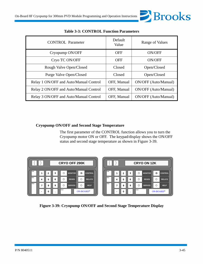
On-Board 8F Cryopump for 300mm PVD Module Programming and Operation Instructions
P/N 8040511 3-45
Cryopump ON/OFF and Second Stage Temperature
The first parameter of the CONTROL function allows you to turn the Cryopump motor ON or OFF. The keypad/display shows the ON/OFF status and second stage temperature as shown in Figure 3-39.
Figure 3-39: Cryopump ON/OFF and Second Stage Temperature Display
Table 3-3: CONTROL Function Parameters
CONTROL ParameterDefault Value
Range of Values
Cryopump ON/OFF OFF ON/OFF
Cryo TC ON/OFF OFF ON/OFF
Rough Valve Open/Closed Closed Open/Closed
Purge Valve Open/Closed Closed Open/Closed
Relay 1 ON/OFF and Auto/Manual Control OFF, Manual ON/OFF (Auto/Manual)
Relay 2 ON/OFF and Auto/Manual Control OFF, Manual ON/OFF (Auto/Manual)
Relay 3 ON/OFF and Auto/Manual Control OFF, Manual ON/OFF (Auto/Manual)
Last
Next
Clear
MONITOR
REGEN
SERVICE
CONTROL
RELAYS
HELP
ooON-BOARD®Enter
1 2 3
4 5 6
7 8 9
- 0 .
CRYO OFF 290K
Last
Next
Clear
MONITOR
REGEN
SERVICE
CONTROL
RELAYS
HELP
ooON-BOARD®Enter
1 2 3
4 5 6
7 8 9
- 0 .
CRYO ON 12K

Programming and Operation
3-46 P/N 8040511
Cryo TC ON/OFF and TC Pressure
The second parameter of the CONTROL function allows you to turn the Cryopump thermocouple gauge ON or OFF. The keypad/display shows the ON/OFF status of the thermocouple pressure as shown in Figure 3-40.
NOTE: The TC INTERLOCK message appears and the Cryo TC Gauge will not turn ON when the second stage temperature is above 20K. The CRYO TC Gauge turns OFF automatically if the temperature goes above 20K. If the temperature is above 20K, the Cryo TC Gauge can only be turned ON if the purge and roughing valves have been opened for regeneration.
Figure 3-40: Cryo TC ON/OFF and TC Pressure Display
Last
Next
Clear
MONITOR
REGEN
SERVICE
CONTROL
RELAYS
HELP
ooON-BOARD®Enter
1 2 3
4 5 6
7 8 9
- 0 .
CRYO TC = OFF
Last
Next
Clear
MONITOR
REGEN
SERVICE
CONTROL
RELAYS
HELP
ooON-BOARD®Enter
1 2 3
4 5 6
7 8 9
- 0 .
CRYO TC 150µ

On-Board 8F Cryopump for 300mm PVD Module Programming and Operation Instructions
P/N 8040511 3-47
Rough Valve Open/Closed
CAUTION
Opening the rough valve when the Cryopump is turned ON may cause oil from the roughing pump to backstream into the vacuum chamber and contaminate the Cryopump arrays. A message is displayed on the keypad/display warning you about this potential problem.
The third parameter of the CONTROL function allows you to open or close the rough valve as shown in Figure 3-41.
Figure 3-41: Rough Valve Open/Closed Display
Last
Next
Clear
MONITOR
REGEN
SERVICE
CONTROL
RELAYS
HELP
ooON-BOARD®Enter
1 2 3
4 5 6
7 8 9
- 0 .
ROUGH V OPEN
Last
Next
Clear
MONITOR
REGEN
SERVICE
CONTROL
RELAYS
HELP
ooON-BOARD®Enter
1 2 3
4 5 6
7 8 9
- 0 .
ROUGH V CLOSED
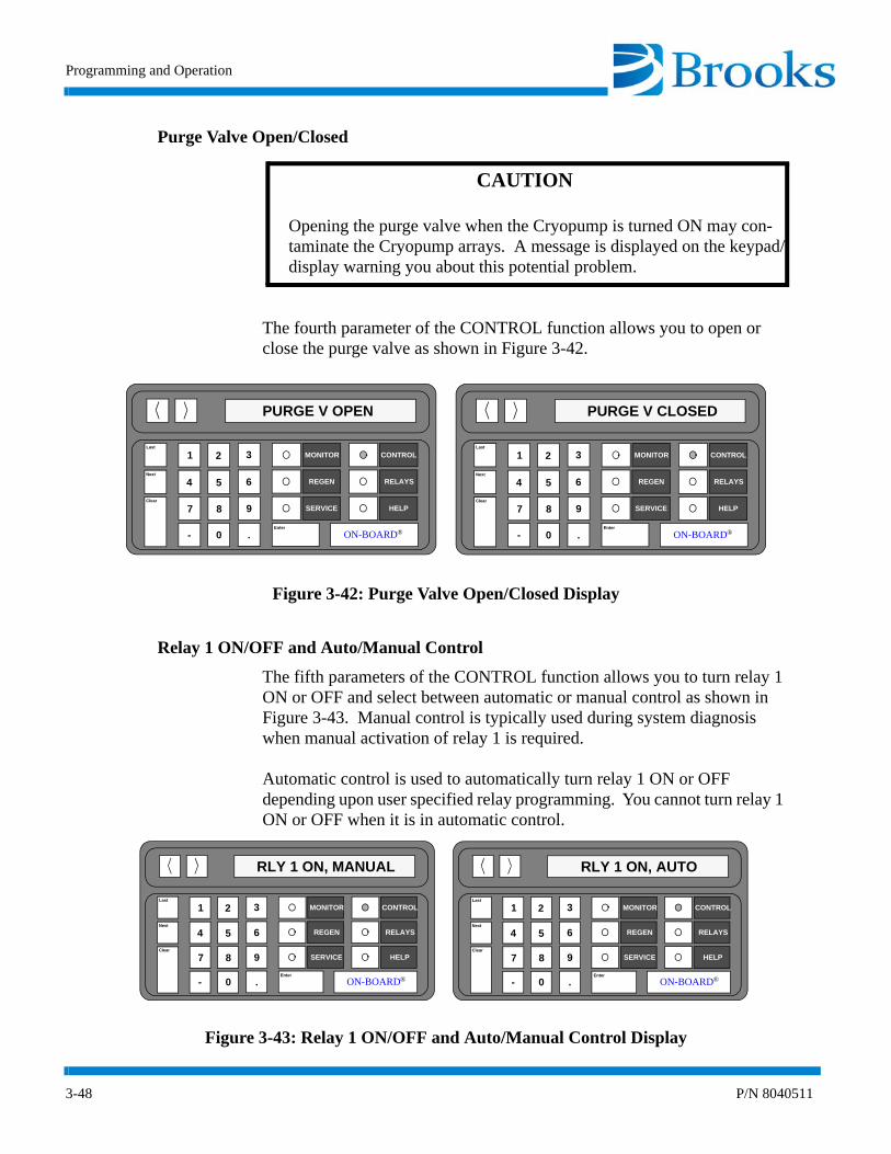
Programming and Operation
3-48 P/N 8040511
Purge Valve Open/Closed
CAUTION
Opening the purge valve when the Cryopump is turned ON may con-taminate the Cryopump arrays. A message is displayed on the keypad/display warning you about this potential problem.
The fourth parameter of the CONTROL function allows you to open or close the purge valve as shown in Figure 3-42.
Figure 3-42: Purge Valve Open/Closed Display
Relay 1 ON/OFF and Auto/Manual Control
The fifth parameters of the CONTROL function allows you to turn relay 1 ON or OFF and select between automatic or manual control as shown in Figure 3-43. Manual control is typically used during system diagnosis when manual activation of relay 1 is required.
Automatic control is used to automatically turn relay 1 ON or OFF depending upon user specified relay programming. You cannot turn relay 1 ON or OFF when it is in automatic control.
Figure 3-43: Relay 1 ON/OFF and Auto/Manual Control Display
Last
Next
Clear
MONITOR
REGEN
SERVICE
CONTROL
RELAYS
HELP
ooON-BOARD®Enter
1 2 3
4 5 6
7 8 9
- 0 .
PURGE V OPEN
Last
Next
Clear
MONITOR
REGEN
SERVICE
CONTROL
RELAYS
HELP
ooON-BOARD®Enter
1 2 3
4 5 6
7 8 9
- 0 .
PURGE V CLOSED
Last
Next
Clear
MONITOR
REGEN
SERVICE
CONTROL
RELAYS
HELP
ooON-BOARD®Enter
1 2 3
4 5 6
7 8 9
- 0 .
RLY 1 ON, MANUAL
Last
Next
Clear
MONITOR
REGEN
SERVICE
CONTROL
RELAYS
HELP
ooON-BOARD®Enter
1 2 3
4 5 6
7 8 9
- 0 .
RLY 1 ON, AUTO
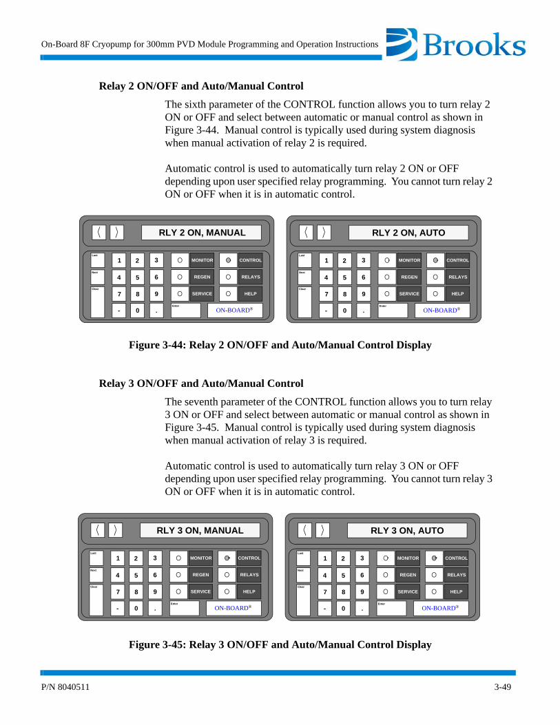
On-Board 8F Cryopump for 300mm PVD Module Programming and Operation Instructions
P/N 8040511 3-49
Relay 2 ON/OFF and Auto/Manual Control
The sixth parameter of the CONTROL function allows you to turn relay 2 ON or OFF and select between automatic or manual control as shown in Figure 3-44. Manual control is typically used during system diagnosis when manual activation of relay 2 is required.
Automatic control is used to automatically turn relay 2 ON or OFF depending upon user specified relay programming. You cannot turn relay 2 ON or OFF when it is in automatic control.
Figure 3-44: Relay 2 ON/OFF and Auto/Manual Control Display
Relay 3 ON/OFF and Auto/Manual Control
The seventh parameter of the CONTROL function allows you to turn relay 3 ON or OFF and select between automatic or manual control as shown in Figure 3-45. Manual control is typically used during system diagnosis when manual activation of relay 3 is required.
Automatic control is used to automatically turn relay 3 ON or OFF depending upon user specified relay programming. You cannot turn relay 3 ON or OFF when it is in automatic control.
Figure 3-45: Relay 3 ON/OFF and Auto/Manual Control Display
Last
Next
Clear
MONITOR
REGEN
SERVICE
CONTROL
RELAYS
HELP
ooON-BOARD®Enter
1 2 3
4 5 6
7 8 9
- 0 .
RLY 2 ON, MANUAL
Last
Next
Clear
MONITOR
REGEN
SERVICE
CONTROL
RELAYS
HELP
ooON-BOARD®Enter
1 2 3
4 5 6
7 8 9
- 0 .
RLY 2 ON, AUTO
Last
Next
Clear
MONITOR
REGEN
SERVICE
CONTROL
RELAYS
HELP
ooON-BOARD®Enter
1 2 3
4 5 6
7 8 9
- 0 .
RLY 3 ON, MANUAL
Last
Next
Clear
MONITOR
REGEN
SERVICE
CONTROL
RELAYS
HELP
ooON-BOARD®Enter
1 2 3
4 5 6
7 8 9
- 0 .
RLY 3 ON, AUTO

Programming and Operation
3-50 P/N 8040511
CONTROL Function Operation
Use the following procedures to operate the CONTROL parameters of the On-Board 8F Cryopump for 300mm PVD Module.
Cryopump ON/OFF and Second Stage Temperature
1. Press the CONTROL key on the keypad/display. The ON/OFF status and the second stage temperature of the Cryopump are displayed.
NOTE: Refer to Appendix A and contact the local CTI-CRYOGENICS customer support center if the letters SHO or OPN are displayed.
2. Press 1 to turn the Cryopump ON, or press 0 to turn the Cryopump OFF.
3. Press the MONITOR key. The On-Board Module software will monitor system operation.
Cryo TC ON/OFF and TC Pressure
1. Press the CONTROL key on the keypad/display. The ON/OFF status and the second stage temperature of the Cryopump are displayed.
2. Press the Next key until the Cryo TC pressure is displayed in microns.
3. Press 1 to turn the CRYO TC ON, or press 0 to turn the Cryo TC OFF.
4. Press the MONITOR key. The On-Board Module software will monitor system operation.
Rough Valve Open/Closed
1. Press the CONTROL key on the keypad/display. The ON/OFF status and the second stage temperature of the Cryopump are displayed.
2. Press the Next key until the current rough valve status is displayed.
3. Press 1 to open the rough valve, or press 0 to close the rough valve.
4. Press the MONITOR key. The On-Board Module software will monitor system operation.

On-Board 8F Cryopump for 300mm PVD Module Programming and Operation Instructions
P/N 8040511 3-51
Purge Valve Open/Closed
1. Press the CONTROL key on the keypad/display. The ON/OFF status and the second stage temperature of the Cryopump are displayed.
2. Press the Next key until the current purge valve status is displayed.
3. Press 1 to open the purge valve, or press 0 to close the purge valve.
4. Press the MONITOR key. The On-Board Module software will monitor system operation.
Relay 1 ON/OFF and Auto/Manual Control
1. Press the CONTROL key on the keypad/display. The ON/OFF status and the second stage temperature of the Cryopump are displayed.
2. Press the Next key until the current status and mode for relay 1 are displayed.
3. Press one of the following number keys for the desired relay activity:
1 to turn relay 1 ON0 to turn relay 1 OFF7 to turn automatic mode ON9 to turn manual mode ON
4. Press the MONITOR key. The On-Board Module software will monitor system operation.
Relay 2 ON/OFF and Auto/Manual Control
1. Press the CONTROL key on the keypad/display. The ON/OFF status and the second stage temperature of the Cryopump are displayed.
2. Press the Next key until the current status and mode for relay 2 are displayed.
3. Press one of the following number keys for the desired relay activity:
1 to turn relay 2 ON0 to turn relay 2 OFF7 to turn automatic mode ON9 to turn manual mode ON

Programming and Operation
3-52 P/N 8040511
4. Press the MONITOR key. The On-Board Module software will monitor system operation.
Relay 3 ON/OFF and Auto/Manual Control
1. Press the CONTROL key on the keypad/display. The ON/OFF status and the second stage temperature of the Cryopump are displayed.
2. Press the Next key until the current status and mode for relay 3 are displayed.
3. Press one of the following number keys for the desired relay activity:
1 to turn relay 3 ON0 to turn relay 3 OFF7 to turn automatic mode ON9 to turn manual mode ON
4. Press the MONITOR key. The On-Board Module software will monitor system operation.
On-Board 8F Cryopump for 300mm PVD Module Programming and Operation Instructions
P/N 8040511 3-53
RELAYS Function
The RELAYS function within the On-Board 8F Cryopump for 300mm PVD Module allows you to program the setpoint relays to open or close when a vacuum system function occurs.
NOTE: Relay activation/deactivation is dependent upon the manner in which the relays are wired, normally open or normally closed.
The RELAYS function parameters are shown in Figure 3-46. Relay parameters and their ranges are provided in Table 3-4 and are described on the following pages.

Programming and Operation
3-54 P/N 8040511
Figure 3-46: RELAYS Function Flowchart
Select Relay
1,2, or 3
RELAYS
HELP
Displays currentON/OFF state and
auto/manual state
Displays current
Set first stagetemperature limits
Set Cryo TCpressure limits
Sets relay to activate
Sets relay to activate
Sets relay to activate
Sets relay activation
user defined program forautomatic control
based on Cryopump
motor ON/OFF
when Cryopump is in
REGEN
when rough valve is open or closed
time delaySet second stagetemperature limits

On-Board 8F Cryopump for 300mm PVD Module Programming and Operation Instructions
P/N 8040511 3-55
Select Relay 1, 2, or 3
The first parameter of the RELAYS function allows you to select setpoint relay 1, 2, or 3 to be programmed as shown in Figure 3-47.
Figure 3-47: Select Relay 1, 2, or 3 Display
Table 3-4: RELAYS Function Parameters
RELAYS Parameter Range of Values
Relay 1, 2, or 3 1 - 3
Relay ON/OFF, Auto/Manual ON/OFF Auto/Manual
First Stage Temperature 30K - 310K
Second Stage Temperature 10K - 310K
Cryo TC Pressure 1 - 999 microns
Cryopump ON/OFF
REGEN Track ON/OFF
Rough Valve ON/OFF
Time Delay 0 - 99 seconds
Last
Next
Clear
MONITOR
REGEN
SERVICE
CONTROL
RELAYS
HELP
ooON-BOARD®Enter
1 2 3
4 5 6
7 8 9
- 0 .
RELAY 1, 2, OR 3

Programming and Operation
3-56 P/N 8040511
Current State of Relay ON/OFF, Auto/Manual
The second parameter of the RELAYS function allows you to determine whether the relay is ON or OFF and in automatic or manual mode shown in Figure 3-48. If in automatic mode, the relay is programmed to activate (ON/OFF) based upon a programmed function as listed.
NOTE: Relay activation is controlled in the CONTROL function if in manual mode.
Automatic control is used to turn the setpoint relay ON or OFF based upon user specified programming. You cannot manually turn the setpoint relay ON or OFF when in automatic control. Manual control is typically used during system diagnosis when manual activation of a setpoint relay is required.
Figure 3-48: Current State of Relay ON/OFF, Auto/Manual
Last
Next
Clear
MONITOR
REGEN
SERVICE
CONTROL
RELAYS
HELP
ooON-BOARD®Enter
1 2 3
4 5 6
7 8 9
- 0 .
RLY 1 OFF, AUTO
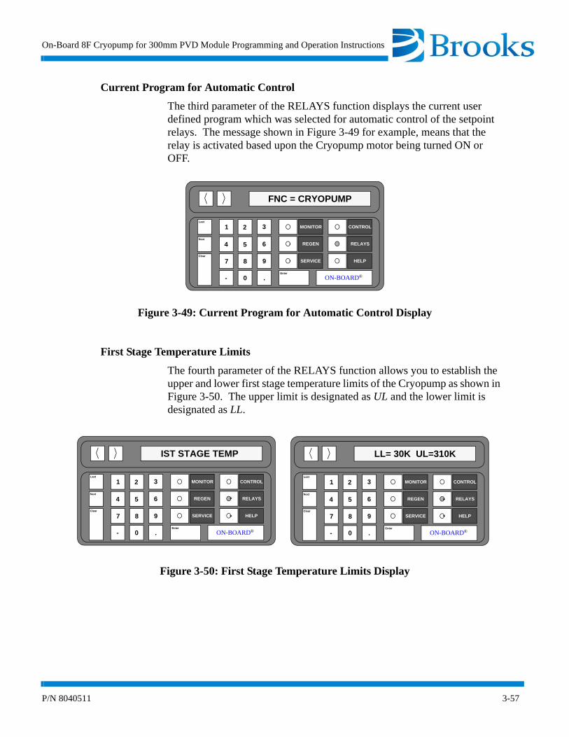
On-Board 8F Cryopump for 300mm PVD Module Programming and Operation Instructions
P/N 8040511 3-57
Current Program for Automatic Control
The third parameter of the RELAYS function displays the current user defined program which was selected for automatic control of the setpoint relays. The message shown in Figure 3-49 for example, means that the relay is activated based upon the Cryopump motor being turned ON or OFF.
Figure 3-49: Current Program for Automatic Control Display
First Stage Temperature Limits
The fourth parameter of the RELAYS function allows you to establish the upper and lower first stage temperature limits of the Cryopump as shown in Figure 3-50. The upper limit is designated as UL and the lower limit is designated as LL.
Figure 3-50: First Stage Temperature Limits Display
Last
Next
Clear
MONITOR
REGEN
SERVICE
CONTROL
RELAYS
HELP
ooON-BOARD®Enter
1 2 3
4 5 6
7 8 9
- 0 .
FNC = CRYOPUMP
Last
Next
Clear
MONITOR
REGEN
SERVICE
CONTROL
RELAYS
HELP
ooON-BOARD®Enter
1 2 3
4 5 6
7 8 9
- 0 .
LL= 30K UL=310K
Last
Next
Clear
MONITOR
REGEN
SERVICE
CONTROL
RELAYS
HELP
ooON-BOARD®Enter
1 2 3
4 5 6
7 8 9
- 0 .
IST STAGE TEMP
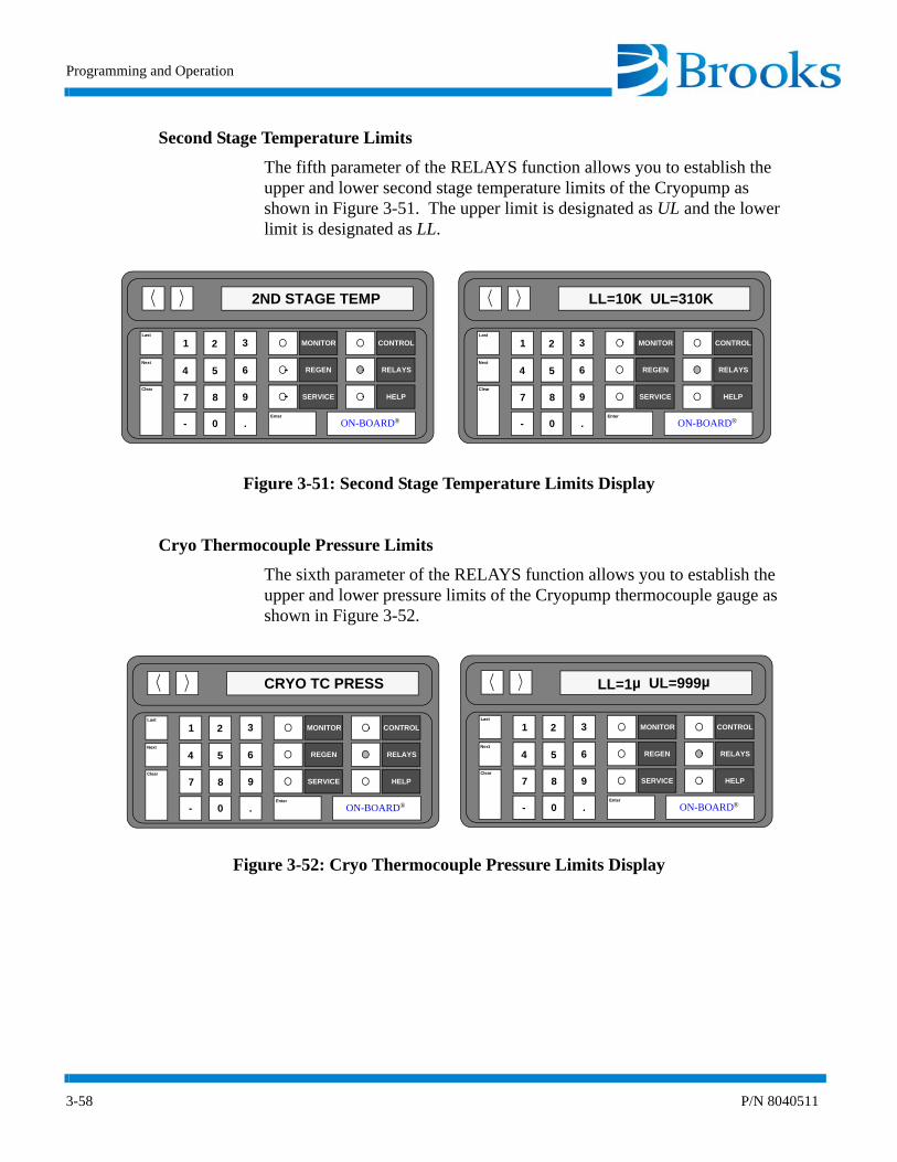
Programming and Operation
3-58 P/N 8040511
Second Stage Temperature Limits
The fifth parameter of the RELAYS function allows you to establish the upper and lower second stage temperature limits of the Cryopump as shown in Figure 3-51. The upper limit is designated as UL and the lower limit is designated as LL.
Figure 3-51: Second Stage Temperature Limits Display
Cryo Thermocouple Pressure Limits
The sixth parameter of the RELAYS function allows you to establish the upper and lower pressure limits of the Cryopump thermocouple gauge as shown in Figure 3-52.
Figure 3-52: Cryo Thermocouple Pressure Limits Display
Last
Next
Clear
MONITOR
REGEN
SERVICE
CONTROL
RELAYS
HELP
ooON-BOARD®Enter
1 2 3
4 5 6
7 8 9
- 0 .
LL=10K UL=310K
Last
Next
Clear
MONITOR
REGEN
SERVICE
CONTROL
RELAYS
HELP
ooON-BOARD®Enter
1 2 3
4 5 6
7 8 9
- 0 .
2ND STAGE TEMP
Last
Next
Clear
MONITOR
REGEN
SERVICE
CONTROL
RELAYS
HELP
ooON-BOARD®Enter
1 2 3
4 5 6
7 8 9
- 0 .
LL=1µ UL=999µ
Last
Next
Clear
MONITOR
REGEN
SERVICE
CONTROL
RELAYS
HELP
ooON-BOARD®Enter
1 2 3
4 5 6
7 8 9
- 0 .
CRYO TC PRESS

On-Board 8F Cryopump for 300mm PVD Module Programming and Operation Instructions
P/N 8040511 3-59
Cryopump
The seventh parameter of the RELAYS function allows you to program the setpoint relay to activate when the Cryopump motor is turned ON and deactivate when the motor is turned OFF as shown in Figure 3-53.
Figure 3-53: Cryopump Display
Regeneration
The eighth parameter of the RELAYS function allows you to program the setpoint relay to activate when the Cryopump is in regeneration mode as shown in Figure 3-54.
Figure 3-54: Regeneration Display
Last
Next
Clear
MONITOR
REGEN
SERVICE
CONTROL
RELAYS
HELP
ooON-BOARD®Enter
1 2 3
4 5 6
7 8 9
- 0 .
CRYOPUMP
Last
Next
Clear
MONITOR
REGEN
SERVICE
CONTROL
RELAYS
HELP
ooON-BOARD®Enter
1 2 3
4 5 6
7 8 9
- 0 .
REGEN TRACK
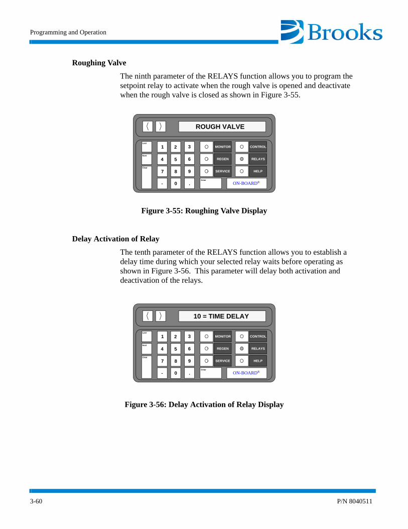
Programming and Operation
3-60 P/N 8040511
Roughing Valve
The ninth parameter of the RELAYS function allows you to program the setpoint relay to activate when the rough valve is opened and deactivate when the rough valve is closed as shown in Figure 3-55.
Figure 3-55: Roughing Valve Display
Delay Activation of Relay
The tenth parameter of the RELAYS function allows you to establish a delay time during which your selected relay waits before operating as shown in Figure 3-56. This parameter will delay both activation and deactivation of the relays.
Figure 3-56: Delay Activation of Relay Display
Last
Next
Clear
MONITOR
REGEN
SERVICE
CONTROL
RELAYS
HELP
ooON-BOARD®Enter
1 2 3
4 5 6
7 8 9
- 0 .
ROUGH VALVE
Last
Next
Clear
MONITOR
REGEN
SERVICE
CONTROL
RELAYS
HELP
ooON-BOARD®Enter
1 2 3
4 5 6
7 8 9
- 0 .
10 = TIME DELAY

On-Board 8F Cryopump for 300mm PVD Module Programming and Operation Instructions
P/N 8040511 3-61
RELAYS Function Operation
Only one Relay parameter can be in control of the relay at anytime. Once a Relay parameter has been programmed, your selected relay will be placed in automatic mode as indicated by the FNC = CRYOPUMP message. FNC is an abbreviation for Function and the message indicates the relay will be activated when the Cryopump motor is turned ON. The previously programmed relay parameter (if one exists) will be cancelled. The FNC = MANUAL OFF message indicates that none of the Relay parameters have been programmed.
Use the following procedures to program the Relay parameters of the On-Board 8F Cryopump for 300mm PVD Module.
NOTE: Relay activation/deactivation is dependent upon the manner in which the relays are wired, normally open or normally closed.
Programming First Stage Temperature Limits
This procedure programs relay 1, 2, or 3 to activate/deactivate when either of the Cryopump first stage temperature limits are reached.
1. Press the RELAYS key on the keypad/display.
2. Press 1, 2, or 3 depending upon which relay is being selected. The selected relay number along with the ON/OFF and Auto/Manual status are displayed.
3. Press the Next key until the 1st Stage Temperature is displayed.
4. Press the Enter key. The cursor is placed under the current lower limit (LL) value.
NOTE: If a number which is not in the proper range is entered, LL-???K or UL-???K will be displayed. Press the Clear button to continue.
5. Using the keypad, enter the new lower limit value.
6. Press the Enter key. The cursor is placed under the current upper limit (UL) value.
7. Using the keypad, enter the new upper limit value.
8. Press the Enter key. The limit values are programmed.
9. Press the MONITOR key. The On-Board Module software will monitor system operation.

Programming and Operation
3-62 P/N 8040511
Programming Second Stage Temperature Limits
This procedure programs relay 1, 2, or 3 to activate/deactivate when either of the Cryopump second stage temperature limits are reached.
1. Press the RELAYS key on the keypad/display.
2. Press 1, 2, or 3 depending upon which relay is being selected. The selected relay number along with the ON/OFF and Auto/Manual status are displayed.
3. Press the Next key until the 2nd Stage Temperature is displayed.
4. Press the Enter key. The cursor is placed under the current lower limit (LL) value.
NOTE: If a number which is not in the proper range is entered, LL-???K or UL-???K will be displayed. Press the Clear button to continue.
5. Using the keypad, enter the new lower limit value.
6. Press the Enter key. The cursor is placed under the current upper limit (UL) value.
7. Using the keypad, enter the new upper limit value.
8. Press the Enter key. The limit values are programmed.
9. Press the MONITOR key. The On-Board Module software will monitor system operation.
Programming Cryo Thermocouple Pressure Limits
This procedure programs relay 1, 2, or 3 to activate/deactivate when either of the Cryopump thermocouple pressure limits are reached.
1. Press the RELAYS key on the keypad/display.
2. Press 1, 2, or 3 depending upon which relay is being selected. The selected relay number along with the ON/OFF and Auto/Manual status are displayed.
3. Press the Next key until Cryo TC Press. appears in the display.
4. Press the Enter key. The cursor is placed under the current lower limit (LL) value.
NOTE: If a number which is not in the proper range is entered, LL-???µ or UL-???µ will be displayed. Press the Clear button to continue.
5. Using the keypad, enter the new lower limit value.
6. Press the Enter key. The cursor is placed under the current upper limit (UL) value.
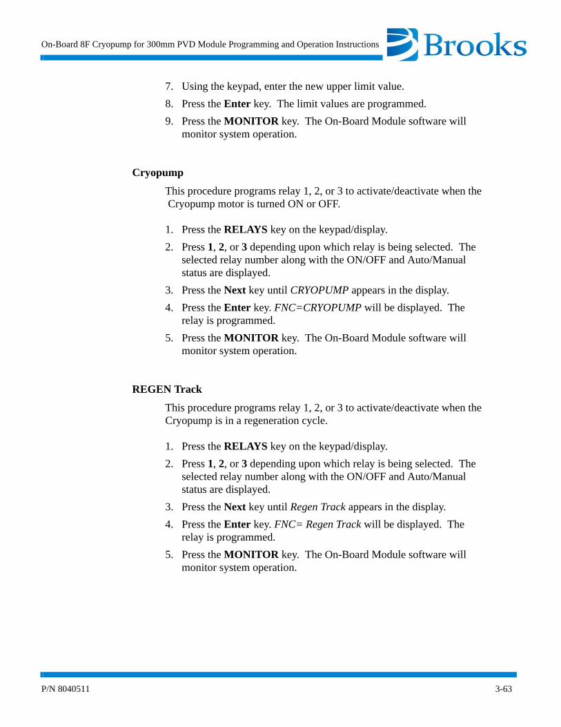
On-Board 8F Cryopump for 300mm PVD Module Programming and Operation Instructions
P/N 8040511 3-63
7. Using the keypad, enter the new upper limit value.
8. Press the Enter key. The limit values are programmed.
9. Press the MONITOR key. The On-Board Module software will monitor system operation.
Cryopump
This procedure programs relay 1, 2, or 3 to activate/deactivate when the Cryopump motor is turned ON or OFF.
1. Press the RELAYS key on the keypad/display.
2. Press 1, 2, or 3 depending upon which relay is being selected. The selected relay number along with the ON/OFF and Auto/Manual status are displayed.
3. Press the Next key until CRYOPUMP appears in the display.
4. Press the Enter key. FNC=CRYOPUMP will be displayed. The relay is programmed.
5. Press the MONITOR key. The On-Board Module software will monitor system operation.
REGEN Track
This procedure programs relay 1, 2, or 3 to activate/deactivate when the Cryopump is in a regeneration cycle.
1. Press the RELAYS key on the keypad/display.
2. Press 1, 2, or 3 depending upon which relay is being selected. The selected relay number along with the ON/OFF and Auto/Manual status are displayed.
3. Press the Next key until Regen Track appears in the display.
4. Press the Enter key. FNC= Regen Track will be displayed. The relay is programmed.
5. Press the MONITOR key. The On-Board Module software will monitor system operation.

Programming and Operation
3-64 P/N 8040511
Rough Valve
This procedure programs relay 1, 2, or 3 to activate/deactivate when the rough valve opens/closes.
1. Press the RELAYS key on the keypad/display.
2. Press 1, 2, or 3 depending upon which relay is being selected. The selected relay number and the ON/OFF and Auto/Manual status are displayed.
3. Press the Next button until Rough Valve appears in the display.
4. Press the Enter key. FNC = Rough Valve is displayed. The relay is programmed.
5. Press the MONITOR key. The On-Board Module software will monitor system operation.
Time Delay
This procedure programs relay 1, 2, or 3 to delay activation/deactivation by a user determined amount of time.
1. Press the RELAYS key on the keypad/display.
2. Press 1, 2, or 3 depending upon which relay is being selected. The selected relay number along with the ON/OFF and Auto/Manual status are displayed.
3. Press the Next key until the current Time Delay value appears in the display.
4. Press the Enter key.
5. Using the keypad, enter the desired amount of delay time (in sec-onds).
6. Press the Enter key. The new time delay value is programmed.
7. Press the MONITOR key. The On-Board Module software will monitor system operation.
On-Board 8F Cryopump for 300mm PVD Module Software Function Parameters
Table 3-5 provides you with a complete listing of all On-Board 8F Cryopump for 300mm PVD Module Software parameters. This table can be used as a quick reference to locate parameters within the MONITOR, REGEN, SERVICE, CONTROL, and RELAYS functions.

On-Board 8F Cryopump for 300mm PVD Module Programming and Operation Instructions
P/N 8040511 3-65
Table 3-5: On-Board 8F Cryopump for 300mm PVD Module Software Parameters
MONITOR REGEN SERVICE CONTROL RELAYS
CryopumpON/OFF
Second Stage Temperature
REGEN ON/OFF Software Version Cryopump ON/OFF
Second Stage Temperature
Relay 1, 2, or 3
First and Second Stage Temperature
Delay Start Net ID Cryo TC ON/OFF
RelayON/OFF,
Auto/Manual
First Stage Temperature
Delay Restart Elapsed Pump Time Rough Valve Open/Closed
Current RelayProgram
Second Stage Temperature
Fast Rough Test Time Since Last Full REGEN
Purge Valve Open/Closed
First Stage Temperature
Cryo TC GaugePressureON/OFF
Extended Purge Time Since Last Fast Regeneration
Relay 1 ON/OFF and Auto/
Manual Control
Second Stage Temperature
Relay 1 ON/OFF and Auto/
Manual Control
Repurge Password Relay 2 ON/OFF and Auto/
Manual Control
Cryo TC Pressure
Relay 2 ON/OFF and Auto/
Manual Control
Repurge Cycles Lock Mode Relay 3 ON/OFF and Auto/
Manual Control
Cryopump
Relay 3 ON/OFF and Auto/
Manual Control
Base Pressure Parameter Lock REGEN Track
Rate-of-Rise (ROR) Zero Cryopump Thermocouple
Rough Valve
ROR Cycles First Stage Temperature
Control
Time Delay
Rough Valve Interlock
Power Fail Recovery
Power Fail Recovery
Temperature

Programming and Operation
3-66 P/N 8040511
This Page Intentionally Left Blank

Appendix A - Customer Support Information
A-1
Appendix A - Customer Support Information
Customer Support Center Locations
To locate a Customer Support Center near you, please visit our website www.helixtechnology.com on the world wide web and select CONTACT on the home page.
Guaranteed Up-Time Support (GUTS)
For 24 hour, 7 day per week Guaranteed Up-Time Support (GUTS) dial:
800-367-4887 - Inside the United States of America
508-337-5599 - Outside the United States of America
Product Information
Please have the following information available when calling so that we may assist you:
• Product Part Number
• Product Serial Number
• Product Application
• Specific Problem Area
• Hours of Operation
• Equipment Type
• Vacuum System Brand/Model/Date of Manufacture
For your convenience, you may also e-mail us at:

Appendix A - Customer Support Information
A-2
This Page Intentionally Left Blank

On-Board 8F Cryopump for 300mm PVD Module Programming and Operation Instructions
P/N 8040511 B-1
Appendix B - RS-232 Interface Protocol Format
The format of RS-232 messages between a computer device (the HOST) and the On-Board 8F Cryopump for 300mm PVD Module (slave) is the same for both directions of message flow (HOST transmitted or slave transmitted). Each message consists of a series of ASCII characters trans-mitted via a standard RS-232 asynchronous framing convention of one (1) start bit, seven (7) data bits, a parity bit generated for even parity, and one (1) stop bit; at a transmission rate of 9600 baud.
The message packet is composed of a starting flag character (the $character, hex 24), followed by a message dependent data field, followed by a message checksum character, terminated by an ASCII carriage return code (hex 0D). The starting flag character serves the unique purpose of synchronizing the receiver to the transmitter, by signaling the start of the message packet. This '$' code is not contained in the set of characters used to construct the data field or the checksum character, and therefore establishes a fixed reference point to sync up data flow. Whenever either receiver (HOST or slave) receives a '$' character, all history and status of previous partial packet data (if any) is aborted and lost, and a packet message is started anew.
The data field consists of from one (1) to a maximum of fourteen (14) ASCII characters, the meaning of which is defined in the Pump Command List for commands and responses. All characters with the exception of '$' and Carriage-Return (0D hex) may be employed in the data field, if suitable.
The message checksum character is employed to guard against garbled or incorrect messages being received and acted upon, causing undesirable or damaging results. Only messages which are conveyed accurately and intact from the master to slave (or visa versa) are accepted and acted upon. The checksum character which follows the data field is computed by a modified binary sum technique (described later) over the characters composing the data field. The transmitting unit generates this sum based on the characters it used to produce the data field, and appends it after the field just prior to the CR code terminator. The receiving unit performs the same checksum algorithm on all characters which it receives between the '$' character and the character just prior to the CR terminator (non-inclusive).
Appendix B - RS-232 Interface Protocol Format
B-2 P/N 8040511
If this sum matches the final character preceding the CR terminator, then the message is validated and processed by the receiver. If not, then an error has occurred and the action taken depends on whether the receiver is the HOST or slave unit. The checksum algorithm generates a character between ASCII '0' and 'o' (30 hex to 6F hex) inclusive.
The checksum algorithm is defined as follows: Perform the 8 bit (modulo 256) sum of all the ASCII characters sent in the data field (with the most significant bit cleared to 0, ignore parity). This is performed for one to fourteen character code bytes. Fold the resulting eight bit sum into six bits by exclusive oring the two MSBs of the sum (D7, D6) with the two LSBs (D1, D0) of the sum such that the new D1 is the old D1 XOR D7 and the new D0 is the old D0 XOR D6. The resulting lower six bits (D5 . . D0) are then masked off, producing a code range of from 00 to 3F hex. This is then added to the ASCII code for '0' (30 hex), generating the final printable checksum character in the range of 30 hex to 6F hex ('0' . . 'o').
Message traffic is always originated by the HOST unit. This message is referred to as a command or query. Commands cause specific actions to occur in the On-Board Module. Queries request that the module reply with status or other parametric information. The module responds to all such correctly received messages with a response message. The pairing of these command-response or query-response message sets defines a transaction or exchange. If a faulty message is received by the On-Board Module (due to improper production in the host, or transmission media failure), the mes-sage is discarded and no response is sent back to the host as a reply. The host must be able to detect that either no response or an invalid response was received from the slave (through time-out and checksum detection), and if desired, repeat the message to the slave in an attempt to secure a valid transaction.
All communications between a host computer and the On-Board Module will occur within this message transaction framework. Software operating on the host computer must generate and interpret the message-response pairs to properly execute and control remote operation and data-logging of the On-Board Module. Software within the On-Board Module interprets these valid messages and returns appropriate replies, as documented in the On-Board Module RS-232 command list. Error code messages may be returned by the On-Board Module if a valid message packet is received but the data field contents are not correct and cannot be interpreted.
On-Board 8F Cryopump for 300mm PVD Module Programming and Operation Instructions
P/N 8040511 B-3
This is not a communications error, but a software error. Invalid com-mands, improper parameter ranges, or requests to perform operations which are disallowed for some reasons all result in an error message reply.
There are three categories of error messages. Each category has two possi-ble messages. The first is an error under normal conditions. The second is an error message that also signals a recent power loss. If a power loss sig-nal is received, this flag can be reset by using the S command .
1. The normal reply for an understandable and executable mes-sage is A. If this inquiry is the first since a power failure, the message is B.
2. If a command is sent that cannot be executed under any conditions, the error message is E. If this inquiry is the first since a power fail-ure, the message is F.
3. If a command is sent that cannot be executed except under certain conditions, due to interlocks, the return message is G. If this inquiry is the first since a power failure, the message is H.
NOTE: If using a Network Teminal (48 VDC) or On-Board Central Con-trol software (OCC), the only reply you will see will be "A". This reply occurs because the error messages will have been cleared by the Network Teminal or OCC software. If your system utilizes a Network Teminal or OCC software, you should use the lower case t command as described in Table B-1 (within this appendix) and Appendix E if you wish to have your system controller recognize a power failure signal which is recorded in the pump.
Between the time that the host sends a command/ query and the slave returns a response message, further characters sent from the host to the slave are ignored. The slave will respond to any verified message packet it receives within one second. A timeout period in excess of this within host can be used to detect a failure and need to re-try. Once a response to a message has been received by the host, new command/query messages may be immediately sent out (at a rate that will be faster than the one-sec-ond turnaround timeout). In this way the message traffic is self synchronizing.
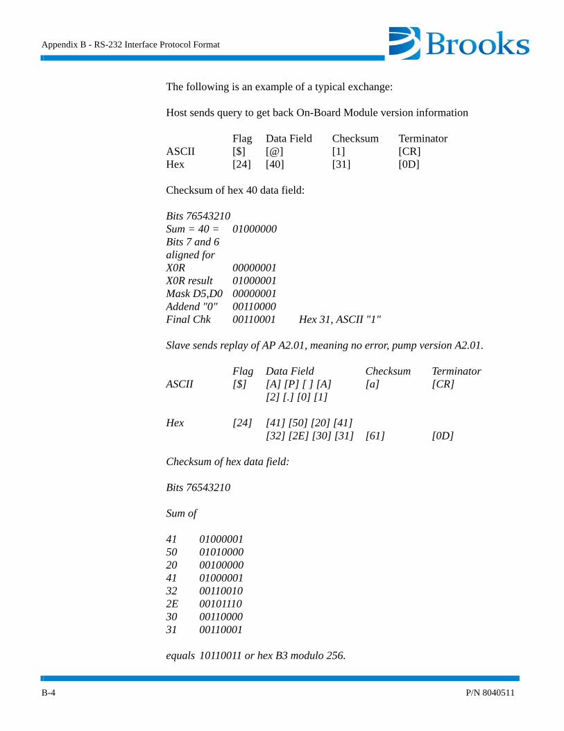
Appendix B - RS-232 Interface Protocol Format
B-4 P/N 8040511
The following is an example of a typical exchange:
Host sends query to get back On-Board Module version information
Flag Data Field Checksum TerminatorASCII [$] [@] [1] [CR]Hex [24] [40] [31] [0D]
Checksum of hex 40 data field:
Bits 76543210Sum = 40 = 01000000Bits 7 and 6aligned forX0R 00000001X0R result 01000001Mask D5,D0 00000001Addend "0" 00110000Final Chk 00110001 Hex 31, ASCII "1"
Slave sends replay of AP A2.01, meaning no error, pump version A2.01.
Flag Data Field Checksum TerminatorASCII [$] [A] [P] [ ] [A] [a] [CR]
[2] [.] [0] [1]
Hex [24] [41] [50] [20] [41][32] [2E] [30] [31] [61] [0D]
Checksum of hex data field:
Bits 76543210
Sum of
41 0100000150 0101000020 0010000041 0100000132 001100102E 0010111030 0011000031 00110001
equals 10110011 or hex B3 modulo 256.
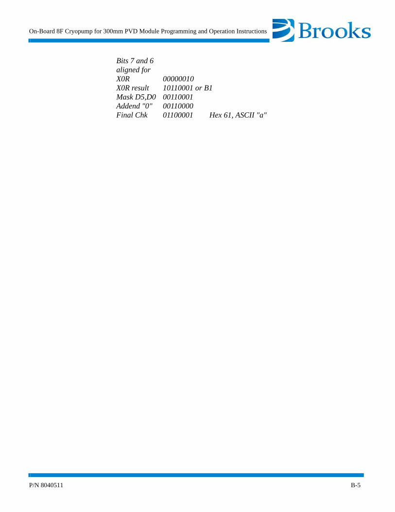
On-Board 8F Cryopump for 300mm PVD Module Programming and Operation Instructions
P/N 8040511 B-5
Bits 7 and 6aligned forX0R 00000010X0R result 10110001 or B1Mask D5,D0 00110001Addend "0" 00110000Final Chk 01100001 Hex 61, ASCII "a"

Appendix B - RS-232 Interface Protocol Format
B-6 P/N 8040511
Figure B-1: RS-232 Cable Connections
2 R x D <-
3 T x D ->
9
5
Shield
9 Pin Male
<- T x D 2
<- R x D 3
GND 7
25 Pin Female
On-Board ModulePC
CAUTION
The RS-232 cable should not be routed with power cables andother equipment which may generate excessive EMI conditions.
2 R x D <-
3 T x D ->
9
5
Shield
9 Pin Male
On-Board Module
<- T x D 3
-> R x D 2
GND 5
9 Pin Female
PC
On-Board Module to IBM-AT
On-Board Module to PC
NOTE: Connectors should be of a metal case type and cable lengths should not exceed 40 feet.

On-Board 8F Cryopump for 300mm PVD Module Programming and Operation Instructions
P/N 8040511 B-7
Table B-1: On-Board Module RS-232 Commands
Command Parameter Description
A [0 - 1] | [?] Turns the pump ON and OFF and provides status:0 - Turns pump OFF1 - Turns pump ON? - Provides pump status
B [0 - 1] | [?] Turns the pump TC ON and OFF0 - Turns TC OFF1 - Turns TC ON? - Provides TC status
D [0 - 1] | [?] Opens or closes the rough valve and provides status.0 - Closes rough valve1 - Opens rough valve? - Provides rough valve status
E [0 - 1] | [?] Opens or closes the purge valve and provides status.0 - Closes purge valve1 - Opens purge valve? - Provides purge valve status
H [0 - 320] [?] Sets temperature control of the first stage. Temperature control is turned OFF if set to "0". A "?" reads back the current value of 0-320.
J None Sends back the first stage temperature.
K None Sends back second stage temperature.
L None Sends back the pump TC pressure.
N [0 - 2} Starts or aborts a regeneration cycle.0 - Aborts regeneration1 - Starts regeneration2 - Starts fast regeneration
O None Sends back the current regeneration step. Refer to Appendix C for the ASCII codes.

Appendix B - RS-232 Interface Protocol Format
B-8 P/N 8040511
P [0 - 6,A,G,S] [5 digit number]
| [?]
Reads/Sets a regeneration parameter.
0 = Pump restart delay (minutes) range = 0 - 599941 = Extended purge time (minutes) range = 0 - 99992 = Repurge cycles 0 - 203 = Rough to pressure range = 25 - 2004 = Rate-of-rise (microns/minute) range = 1 - 1005 = ROR cycles range = 0 - 406 = Start-up temperature (after power failure) range = 0 - 80A = Clear/set rough valve interlock range = 0 - 1G = Repurge time (minutes) range = 0 - 9999S = Fast rough test range = 10 - 999
Table B-1: On-Board Module RS-232 Commands (Continued)
Command Parameter Description

On-Board 8F Cryopump for 300mm PVD Module Programming and Operation Instructions
P/N 8040511 B-9
Q [NONE] [?] Rough valve interlock. If no parameter is specified, the valve token is given to the pump. Once the pump has the token, it will keep it until it is done with the rough valve.
During a query (?), the result bits are biased (arithmetically) with '0'. After subtraction of the bias a bit 0 ON (1) indicates that the pump has the token.
A bit 0 ON (1) indicates that the pump has the token.
A bit 1 ON (2) indicates the pump needs the valve token for REGEN.
A bit 2 ON (4) indicates the cryopump is on (PUMP_ON is TRUE). This is used for auto-compressor power up.
The following applies to a Full regeneration:
Valid returns are '0' . . '7'. A '0' or '4' means that the pump hasgiven the flag back.
The following applies to a Fast regeneration:
For Fast regeneration pumps, an additional character is added to the response and a fixed bit 3 weight (8) is always present in the first character telling the Network Terminal or other querying agent that a second byte follows with meaningful Fast regenera-tion flag information. This second character is '0' biased as the first, with new bit weights defined as follows:
A bit 0 ON (1) indicates the pump needs the rough valve for a shared Fast regeneration.
Valid returns are ’0’ or ’4’ for pump OFF/ON with no REGEN.Returns of ’2’, ’3’, ’6’, and ’7’ are normal REGEN need/got.
Table B-1: On-Board Module RS-232 Commands (Continued)
Command Parameter Description

Appendix B - RS-232 Interface Protocol Format
B-10 P/N 8040511
S 1 - 3 Send back various status indicators.
Status 101H = Pump ON02H = Rough valve ON04H = Purge valve ON08H = Cryo TC ON10H = Aux TC ON20H = A result of 0 means that there was a power failure. The bit is reset to 1 after this query.
Status 201H = Setpoint 1 ON02H = Setpoint 2 ON08H = First stage temperature control ON
Status 301H = Pump phase 1 check02H = Pump phase 2 check
Table B-1: On-Board Module RS-232 Commands (Continued)
Command Parameter Description

On-Board 8F Cryopump for 300mm PVD Module Programming and Operation Instructions
P/N 8040511 B-11
T [1-3] {[0-8,ABCF]
[4 digit number]| {[?] [0,1,2,8]}
This command programs the setpoint relays. The first parame-ter tells the relay number (1, 2, or 3). The second parameter is one of two forms. The first, used for setting the item to be pro-grammed, consists of a selector (0-8, ABCF). This form is fol-lowed by a third parameter, a 4 four digit number, if the selector is 0 - 8. The A - F selectors do not require a following numeric parameter, as they are logical function settings.
The second form is used to query the settings and consists of the "?" command element followed by a selector (0-2, 8) to indicate what data is being queried.
Selector meaning for first form:0 = Set first stage LL (deg Kelvin)1 = Set first stage UL2 = Set second stage LL (deg Kelvin)3 = Set second stage UL4 = Set Pump TC LL (microns)5 = Set Pump TC UL8 = Set time relay (0-9999 seconds)A = Set unconditional ONB = Set unconditional OFFC = Set as REGEN status tracking relayD = Set as rough valve tracking relayF = Set as pump motor ON/OFF status tracking relay
Selector meaning for second form:0:=Query previously set LL (meaning depends upon previous use)
1:=Query previously set UL (meaning depends upon previous use)
2:=Query last sent first form selector (0-7, A,B) used to establish particular relay function8:=Query relay time delay (0-9999 seconds)
Examples: "$T 1 2 25" /* Set relay 1 second stage LL to 25K"$T 1 8 30" /* Set relay 1 time delay to 30 seconds"$T 1 ? 0" /* Query relay 1 last LL value"$T 1 ? 2" /* Query mode of relay startup for relay 1, returns 0 - 7 A - F as characters
VA [?] Reads first 8 characters of pump serial number.
Table B-1: On-Board Module RS-232 Commands (Continued)
Command Parameter Description
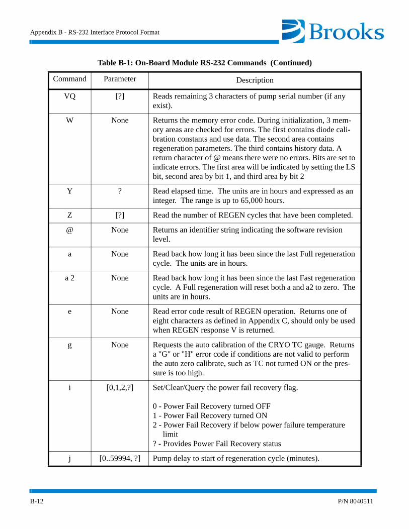
Appendix B - RS-232 Interface Protocol Format
B-12 P/N 8040511
VQ [?] Reads remaining 3 characters of pump serial number (if any exist).
W None Returns the memory error code. During initialization, 3 mem-ory areas are checked for errors. The first contains diode cali-bration constants and use data. The second area contains regeneration parameters. The third contains history data. A return character of @ means there were no errors. Bits are set to indicate errors. The first area will be indicated by setting the LS bit, second area by bit 1, and third area by bit 2
Y ? Read elapsed time. The units are in hours and expressed as an integer. The range is up to 65,000 hours.
Z [?] Read the number of REGEN cycles that have been completed.
@ None Returns an identifier string indicating the software revision level.
a None Read back how long it has been since the last Full regeneration cycle. The units are in hours.
a 2 None Read back how long it has been since the last Fast regeneration cycle. A Full regeneration will reset both a and a2 to zero. The units are in hours.
e None Read error code result of REGEN operation. Returns one of eight characters as defined in Appendix C, should only be used when REGEN response V is returned.
g None Requests the auto calibration of the CRYO TC gauge. Returns a "G" or "H" error code if conditions are not valid to perform the auto zero calibrate, such as TC not turned ON or the pres-sure is too high.
i [0,1,2,?] Set/Clear/Query the power fail recovery flag.
0 - Power Fail Recovery turned OFF1 - Power Fail Recovery turned ON2 - Power Fail Recovery if below power failure temperature limit? - Provides Power Fail Recovery status
j [0..59994, ?] Pump delay to start of regeneration cycle (minutes).
Table B-1: On-Board Module RS-232 Commands (Continued)
Command Parameter Description

On-Board 8F Cryopump for 300mm PVD Module Programming and Operation Instructions
P/N 8040511 B-13
k None Returns an internal interval timer value in minutes. When in the appropriate phase, this value represents the time remaining in the phase (delay start, cryo restart, purge time). Times from 1 to 60 seconds return as 1 minute. Times from 61 seconds to 120 seconds return as 2 minutes. Zero returns as 0 minutes.
l None Returns the number of failed purge cycles as an integer value. This value starts at "0" and increments each time a purge phase fails.
m None Returns the number of failed and extended ROR test cycles as an integer value. This value starts at "0" and increments each time a ROR test phase fails.
n None Returns the last measured ROR value computed during a ROR test cycle as an integer value. This value matches that pre-sented on the keypad/display.
r P, form is rP Polls an event count value which specifies the completion of the pump (P) or auto zero sequence. This value is used by a remote computer to tell when an initiated auto zero is complete.
Returns a modulo 256 (0-255) numeric value which is incre-mented each time the auto zero operation completes. The remote unit can detect the completion of the event by a change in value.
s None Polls an event count modulo 256 (0-255) which is incremented each time a REGEN cycle is performed. Used to indicate whether the REGEN idle message should be REGEN COM-PLETE or REGEN OFF.
t ? | =, form is t? or t=
Command to either inquire (t?) or acknowledge and clear (t=) the power recovery flag. A response of 1 is COOLDOWN, 2 is REGENERATION, 3 is IN PROCESS, 4 is RECOVERED, 5 is CHECK PUMP TEMP. Clear the flag with the t= command after inquiring on the flag value.
Table B-1: On-Board Module RS-232 Commands (Continued)
Command Parameter Description

Appendix B - RS-232 Interface Protocol Format
B-14 P/N 8040511
v None Inquires pump for several regeneration flag conditions com-bined as bits in one response. The bits are biased by "@" for ASCII printable results. The bit weights are:
01H - Waiting for rough valve.02H - Purge gas failure detected in regeneration.04H - Heater failure detected in regeneration08H - Fast regeneration has recovered from purge gas failure.10H - Fast regeneration crossed over to a full regeneration.20H - True when fast regeneration has started.
z [0,1, ?] Set/Clear/Query the user keypad access lockout state. When True, the user is limited to the use of the MONITOR and SERVICE functions on the keypad/display.
[B 1 - 3 Restore relay 1, 2, or 3 to automatic settings from manual mode.
Table B-1: On-Board Module RS-232 Commands (Continued)
Command Parameter Description

On-Board 8F Cryopump for 300mm PVD Module Programming and Operation Instructions
P/N 8040511 C-1
Appendix C - RS-232 Regeneration Responses
Introduction
Appendix C describes the On-Board Module REGEN responses which are requested by host computer O status command. The regeneration responses inform the host computer of the regeneration cycle status of the On-Board 8F Cryopump for 300mm PVD Cryopump.
NOTE: In some cases there are several responses which mean the same thing.
Regeneration Response Description
Refer to Table C-1 for a complete description of the regeneration responses.
NOTE: Regeneration responses identified with an asterisk (*) apply to FastRegen responses. Regeneration responses not identified with an asterisk apply to Full regeneration responses.
Responses to the O command are A - z (equal to numeric codes 0 - 57 and 58 - N). The numeric return information is preceeded by the plus sign (+).

Appendix C - RS-232 REGEN Responses
C-2 P/N 8040511
Table C-1: RS-232 REGEN Responses and Descriptions
REGEN Response Description
A,\ Cryopump OFF
B, C, E ,^, ] WARM-UP - During warm-up you may also want to display the actual second stage temperature and the temperature it is attempt-ing to reach.
Example: WARM-UP 272K/310K The 310 is fixed and the 272 is the response from the command K.
D, F, G, Q, R PURGE GAS FAILURE - means that there is a failure with the purge gas. The On-Board 8F Cryopump for 300mm PVD Module will not turn the heaters on and the warmup temperature is reduced to 285K. You should be aware that there is a problem with the purge gas when this response appears.
The D response means purge gas fail if the repsonse to "v" is equal to 8. If the response to "v" is 4, the heater failure message should be displayed.
Example: PURGE GAS FAILURE. . .WARM-UP 234K/285K
H, S EXTENDED PURGE REPURGE CYCLE
This response is used in conjunction with lowercase l and k
An H response means that the pump has reached its warm-up temper-ature and the purge is being extended for some amount of time. The time is determined when the regeneration parameters are programmed. If the response to 1 is 0, then this is called EXTENDED PURGE. If the response to 1 is greater than 1, then this is called REPURGE CYCLE. The time remaining in minutes is com-mand k.
Example: EXTENDED PURGE 12 MIN l = 0 k = 12 REPURGE CYCLE 9 MIN l = 1 k = 9 REPURGE CYCLE #2 5 MIN l = 2 k = 5

On-Board 8F Cryopump for 300mm PVD Module Programming and Operation Instructions
P/N 8040511 C-3
I,J,K, T, a*, b*, j*, n*
ROUGH TO BASE
Purging is completed and the pump is being roughed to a base pres-sure. This is displayed showing the actual pressure, and the base pressure it is attempting to reach. The commands for this information are L actual pressureP3? Pressure attempting to reach (programmed value)
Example: ROUGH 325u/100u = ROUGH actual pressure/try to reach pressureROUGH L u/P3?u
NOTE: If this is a multi-pump system, the pump roughing valve may be waiting to use the valve.
The valve use is controlled by a token pass. Use the following com-mand to access this information,
Command Q? A response of 1 means the pump has the token.A response of 2 means the pump needs the token.
L ROR (Rate-of-Rise): In this display we show how many rate-of-rise cycles have been completed, the actual rate-of-rise, and the rate-of-rise it is attempting to reach (the programmed value).
The commands for this information are: m ROR# n Last ROR value (actual rate-of-rise for most recent test) P4? Programmed value for ROR
Example of Display: ROR #1, 34/10 u/MIN ROR #m, n/p4? u/MIN
M,N, c*, d*, o* COOLDOWN
This display shows the actual second stage temperature and the target temperature which is always 17K. The command is: K actual tem-perature
Example of Display: COOLDOWN 125K/17K
Table C-1: RS-232 REGEN Responses and Descriptions (Continued)
REGEN Response Description

Appendix C - RS-232 REGEN Responses
C-4 P/N 8040511
P Regeneration complete
U* Begin Fast regeneration
V REGENERATION ABORTED
If regeneration is aborted, the reason for this can be determined by using command e. The responses and descriptions are listed below:
@ - No error
A,B - WARM-UP TIMEOUT - Did not reach warm-up temperature within 60 minutes.
C - COOLDOWN TIMEOUT - Did not cool down within 5 hours.
E - ROR CYCLE LIMIT WAS REACHED - The pump did not pass the rate-of-rise test within the programmed cycle limit.
F - MANUAL ABORT - Someone manually gave the command to stop regeneration.
G - ROUGH VALVE TIMEOUT - Rough valve was opened for more than 1 hour without closing.
I* - Not cooled <50. Start of Fast regeneration not allowed because the pump is too warm.
W DELAY RESTART
This countdown timer delays starting the pump for cooldown mode after it has been warmed up, roughed out, and passed the ROR test. This is a user programmed value. If the pump has no valves, the delay timer begins when the pump reaches 310K.
To get the timer value in minutes, use the command k. NOTE: Display the time in hours to match the keypad display.
X, Y POWER FAILURE
There was a power failure during the regeneration cycle and the pump will make a decision to cooldown or regenerate. Refer to Appendix D for more information.
Table C-1: RS-232 REGEN Responses and Descriptions (Continued)
REGEN Response Description

On-Board 8F Cryopump for 300mm PVD Module Programming and Operation Instructions
P/N 8040511 C-5
Z DELAY START
NOTE: Applies to Full and Fast Regeneration cycles.
The start of regeneration will be delayed for some time. To get the timer value in minutes, use command k.
NOTE: Display the time in hours to match the keypad display.
O, [ ZEROING TC GAUGE
The TC gauge is being zeroed at the end of regeneration.
f* SHARE REGEN WAIT
Waiting to lock/acquire shared use of rough valve for multi-pump Fast regenerations when using the Network Terminal and the rough valve interlock.
e* REPURGE
This is the special repurge cycle in Fast regeneration that initiates after the pump has failed to rough to the rough test pressure within the customer programmed time.
h* PURGE COORD WAIT
The pump is in a wait mode, waiting for all of the pumps to begin the re-purge cycle. The Fast regeneration process and Network Terminal coordinates the valves to re-purge simultaneously.
i* ROUGH COORD WAIT
The pump is in a wait mode, waiting for all of the pumps to begin roughing. The Fast regeneration process and Network Terminal coor-dinates the valves to rough simultaneously.
k* PURGE GAS FAIL, RECOVERING
At the start of the Fast regeneration, the pump failed the purge gas test. The pump was still coldenough at the end of the test and is attempting to recover back to 17K.
Table C-1: RS-232 REGEN Responses and Descriptions (Continued)
REGEN Response Description
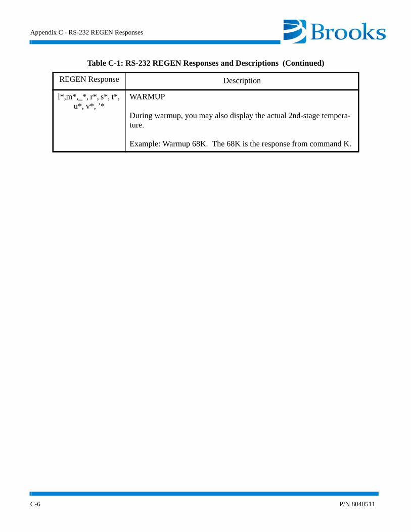
Appendix C - RS-232 REGEN Responses
C-6 P/N 8040511
l*,m*,_*, r*, s*, t*, u*, v*, ’*
WARMUP
During warmup, you may also display the actual 2nd-stage tempera-ture.
Example: Warmup 68K. The 68K is the response from command K.
Table C-1: RS-232 REGEN Responses and Descriptions (Continued)
REGEN Response Description
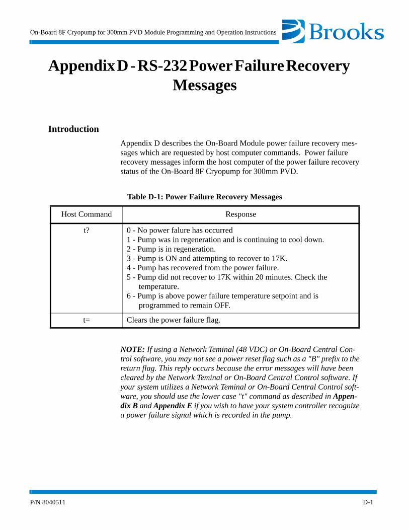
On-Board 8F Cryopump for 300mm PVD Module Programming and Operation Instructions
P/N 8040511 D-1
Appendix D - RS-232 Power Failure Recovery Messages
Introduction
Appendix D describes the On-Board Module power failure recovery mes-sages which are requested by host computer commands. Power failure recovery messages inform the host computer of the power failure recovery status of the On-Board 8F Cryopump for 300mm PVD.
NOTE: If using a Network Teminal (48 VDC) or On-Board Central Con-trol software, you may not see a power reset flag such as a "B" prefix to the return flag. This reply occurs because the error messages will have been cleared by the Network Teminal or On-Board Central Control software. If your system utilizes a Network Teminal or On-Board Central Control soft-ware, you should use the lower case "t" command as described in Appen-dix B and Appendix E if you wish to have your system controller recognize a power failure signal which is recorded in the pump.
Table D-1: Power Failure Recovery Messages
Host Command Response
t? 0 - No power falure has occurred1 - Pump was in regeneration and is continuing to cool down.2 - Pump is in regeneration.3 - Pump is ON and attempting to recover to 17K.4 - Pump has recovered from the power failure.5 - Pump did not recover to 17K within 20 minutes. Check the temperature.6 - Pump is above power failure temperature setpoint and is programmed to remain OFF.
t= Clears the power failure flag.

Appendix D - RS-232 Power Failure Recovery Messages
D-2 P/N 8040511
This Page Intentionally Left Blank

On-Board 8F Cryopump for 300mm PVD Module Programming and Operation Instructions
P/N 8040511 E-1
Appendix E - Keypad/Display Error Messages
Introduction
Appendix E describes the fault messages that can be tested for in the On-Board Module. Currently, each module must be polled for this informa-tion. The module does not automatically send an error message.
Table E-1: Keypad/Display Error Messages
Error Message Response Error Condition
No Pump Power (S3) Logically AND the response with 01H
A result means that 1 phase of power is missing.
Logically AND the response with 02H
A result means that both phases of power are missing.
Heater Failure (v) Logically AND the response with 04H
Logically AND the response with 01H
Logically AND the response with 02H
If TRUE, a heater problem exists and the pump warm-up temperature is reduced to 285K.
If TRUE, rough valve contention exists.
If TRUE, no purge gas was detected and the warm-uptemperature is reduced to 285K.
CRYO TC Gauge inter-lock (B1)
A response of G or H as the first letter after the $ in the response string
Indicates the CRYO TC gauge cannot be turned ON because the temperature of the second stage is above 20K.

Appendix E - Keypad/Display Error Messages
E-2 P/N 8040511
This Page Intentionally Left Blank