officeserv tm 7100 - telephone systems business
TRANSCRIPT
Every effort has been made to eliminate errors and ambiguities in the information contained in this booklet. Any ques-tions concerning information presented here should be directed to SAMSUNG TELECOMMUNICATIONS AMERICA. SAM-SUNG TELECOMMUNICATIONS AMERICA disclaims all liabilities for damages arising from erroneous interpretation oruse of information presented in this manual.
OfficeServTM
7100General Description
Publication Information
SAMSUNG TELECOMMUNICATIONS AMERICA reserves the right without prior notice to reviseinformation in this publication for any reason.
SAMSUNG TELECOMMUNICATIONS AMERICA also reserves the right without prior notice tomake changes in design or components of equipment as engineering and manufacturing maywarrant.
Copyright 2007Samsung Telecommunications America
All rights reserved. No part of this manual may be reproduced in any form or by any means—graphic, electronic or mechanical, including recording, taping, photocopying or informationretrieval systems—without express written permission of the publisher of this material.
PRINTED IN USA 04/07
TABLE OF CONTENTS
PART DESCRIPTION PAGE
1 SYSTEM OVERVIEW1.1 GENERAL DESCRIPTION ..........................................................................................................................1.1
1.2 SIZE AND CONFIGURATION ..................................................................................................................1.3
1.3 TECHNOLOGY ............................................................................................................................................1.6
1.4 PROGRAMMING ........................................................................................................................................1.6
1.5 MIGRATION TO OFFICESERV 7200 OR OFFICESERV 7400............................................................1.6
2 HARDWARE DESCRIPTIONS2.1 SYSTEM CABINET ......................................................................................................................................2.1
2.2 PROCESSOR CARDS ..................................................................................................................................2.1
2.2.1 EMBEDDED APPLICATIONS ......................................................................................................2.1
2.2.2 MULTIMEDIA PLUS CARD ..........................................................................................................2.2
2.3 INTERFACE CARDS ....................................................................................................................................2.2
2.4 DAUGHTERBOARD CARDS ....................................................................................................................2.2
2.5 OFFICESERV 7200/OFFICESERV 7400 TRUNK CARDS ..................................................................2.4
2.6 OFFICESERV 7200/OFFICESERV 7400 VoIP CARDS ........................................................................2.4
2.7 OFFICESERV 7200/OFFICESERV 7400 STATION CARDS................................................................2.4
2.8 STATION EQUIPMENT ..............................................................................................................................2.6
2.8.1 DS 5000 SERIES EQUIPMENT ....................................................................................................2.6
2.8.2 iDCS SERIES EQUIPMENT ..........................................................................................................2.8
2.8.3 OFFICESERV™ ITP-5100 SERIES EQUIPMENT....................................................................2.11
2.8.4 OFFICESERV™ SOFTPHONE....................................................................................................2.12
2.8.5 OFFICESERV™ WIRELESS..........................................................................................................2.12
3 SPECIFICATIONS3.1 ELECTRICAL SPECIFICATIONS................................................................................................................3.1
3.1a I/O VOLTAGE OF PSU ....................................................................................................................3.1
3.2 DIMENSIONS................................................................................................................................................3.1
3.3 ENVIRONMENTAL LIMITS ........................................................................................................................3.2
3.4 CABLE REQUIREMENTS............................................................................................................................3.2
3.5 RING AND TONES ......................................................................................................................................3.2
3.5.1 RING CYCLES....................................................................................................................................3.2
3.5.1a SYSTEM RING CYCLES ................................................................................................................3.2
3.5.2 RING ....................................................................................................................................................3.3
3.5.3 SYSTEM TONES ..............................................................................................................................3.3
3.6 KEYSET LED INDICATIONS ......................................................................................................................3.3
OFFICESERV 7100 FEATURE MAXIMUM CAPACITIES ................................................................................3.4
4 BUSINESS FEATURE PACKAGE
4.1 SYSTEM FEATURES DESCRIPTIONS......................................................................................................4.3
4.2 STATION FEATURES DESCRIPTIONS ..................................................................................................4.28
4.3 DISPLAY FEATURES DESCRIPTIONS ..................................................................................................4.35
4.4 AUTO ATTENDANT FEATURE DESCRIPTIONS ................................................................................4.42
4.5 VOICE MAIL FEATURE DESCRIPTIONS ..............................................................................................4.45
4.6 SAMPLE SMDR PRINTOUT WITH CALLER ID ..................................................................................4.51
4.7 SAMPLE SMDR PRINTOUT WITH CALLER ID/ANI NUMBER ......................................................4.52
4.8 SAMPLE OF UCD EMBEDDED REPORT ............................................................................................4.53
4.9 UCD CALL STATISTICS............................................................................................................................4.54
4.10 UCD AGENT STATISTICS ........................................................................................................................4.56
4.11 SAMPLE TRAFFIC REPORT ....................................................................................................................4.57
4.12 TRAFFIC REPORT OVERVIEW ..............................................................................................................4.58
5 GENERAL USER INFORMATION5.1 RADIO FREQUENCY INTERFERENCE....................................................................................................5.1
5.2 FCC REQUIREMENTS ................................................................................................................................5.1
5.3 TELEPHONE COMPANY INTERFACES ..................................................................................................5.1
5.4 MUSIC ON HOLD WARNING ..................................................................................................................5.3
5.5 DISA WARNING ..........................................................................................................................................5.3
5.6 UNDERWRITERS LABORATORIES..........................................................................................................5.3
STANDARD WARRANTY

Convergence: One Solution (Voice, Data, Wireless)
1.1
OfficeServ ManagementWeb Browser (Data Modules)InternetExplorer 6.0(Voicemail AA)
Data Services4 Port PoE Switch (4SWM)
ApplicationsOS CallOS Operator OS EasySetOS DataviewOS Open TSP
Voice ServicesTDM and
Analog sets
IP Phones WirelessPhone
LAN
PART 1. SYSTEM OVERVIEW
1.1 GENERAL DESCRIPTIONThe OfficeServ 7100 is an “office in a box” solution that converges LAN switching functions (LAN/WAN) with the99.999% reliability of TDM voice processing. The OfficeServ 7100 IP platform supports industry standard Voiceover Internet Protocol (VoIP) as well as the more robust Telephony over IP (ToIP). The integrated Layer 2 PoEswitch module adds powerful access capabilities providing data network solution for your enterprise. Combinethese technologies with Samsung’s Wireless LAN IP Handsets, embedded Voice Mail Application, a suite ofOfficeServ Computer Telephony applications, and much more, all in one powerful platform….A COMPLETE VOICESOLUTION FOR THE ENTERPRISE.
FIGURE 1-1
OfficeServ 7100
Softphone
PSTN
Installation ToolLocal/RemoteProgrammingLAN/MODEMConnectivityDatabaseUpload/DownloadOffline Database ViewingSearch Engine (By MMC/Title)Software Upgrades to MMC+Link to Web Management
The OfficeServ 7100 can be rack-mounted in a standard 19” data rack wall-mounted or set on a desktop. Its com-pact cabinet design, RJ-45 connectors, and CAT 5 cabling allows it to easily integrate into any data center environ-ment along with existing data equipment. Expanding the OfficeServ 7100 system is both economical and easy.With a single cabinet providing 2 universal card slots, its low and high density card design allows greater flexibil-ity when configuring a system for the right combination of lines and stations. A removable software pack MMC+makes it convenient to upgrade to future feature packages.
The OfficeServ 7100 offers a variety of interface cards that allow connection to the public telephone network orto private networks using either analog or digital circuits. Proprietary digital phones called “keysets”connect toDigital Line Interface cards (DLM). In addition to these conventional digital keyset, Samsung offers a completeline-up of IP terminals.These IP terminals use the latest Voice over Internet Protocol (VoIP) technology and can bedeployed over LANs or WANs. They are ideal for distant (remote) locations providing all the benefits of theOfficeServ 7100 to home workers and road warriors. Standard telephones generally called “single line sets” con-nect to single line interface cards (SLM). In addition, DLI station ports are used to connect peripheral devices suchas door phones and add-on modules. Miscellaneous circuits are built-in to allow such optional features as exter-nal paging, music on hold, background music, and common audible devices.
All digital and IP telephones utilize a single PCB with surface-mounted components assuring the highest prod-uct quality and long life. Samsung’s customary large, easy-to-read displays and LEDs in the button design makethem much easier to use. In many instances, sophisticated features are made simple through the use of friendlydisplay prompts or push-on/push-off feature keys.
The OfficeServ 7100 includes all of this, PLUS the same, robust, time proven, market tested feature packageoffered on the OfficeServ 7200 and OfficeServ 7400 products.
BENEFITS
• End to End Samsung components, Samsung Support and Samsung Training. The Ultimate in single sourceShopping and maintenance!
• The OfficeServ 7100 can also integrate into an existing office data network providing many solutions such asisolating voice traffic onto the separate data network.
• The OfficeServ 7100 networks (via SPNET over IP or Qsig over PRI) to other 7100’s or any OfficeServ 7400,7200, 500 or 100 systems.
1.2
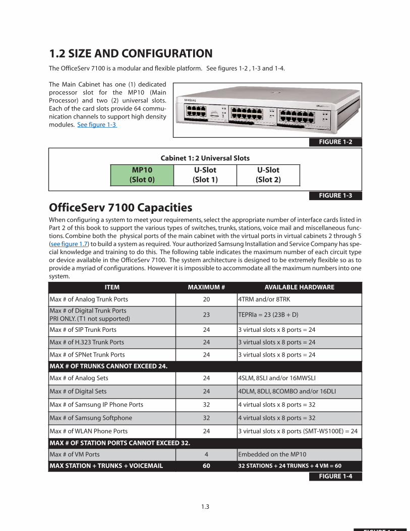
1.2 SIZE AND CONFIGURATIONThe OfficeServ 7100 is a modular and flexible platform. See figures 1-2 , 1-3 and 1-4.
The Main Cabinet has one (1) dedicatedprocessor slot for the MP10 (MainProcessor) and two (2) universal slots.Each of the card slots provide 64 commu-nication channels to support high densitymodules. See figure 1-3
OfficeServ 7100 CapacitiesWhen configuring a system to meet your requirements, select the appropriate number of interface cards listed inPart 2 of this book to support the various types of switches, trunks, stations, voice mail and miscellaneous func-tions. Combine both the physical ports of the main cabinet with the virtual ports in virtual cabinets 2 through 5(see figure 1.7) to build a system as required. Your authorized Samsung Installation and Service Company has spe-cial knowledge and training to do this. The following table indicates the maximum number of each circuit typeor device available in the OfficeServ 7100. The system architecture is designed to be extremely flexible so as toprovide a myriad of configurations. However it is impossible to accommodate all the maximum numbers into onesystem.
FIGURE 1-2
1.3
FIGURE 1-4
Cabinet 1: 2 Universal Slots
MP10(Slot 0)
U-Slot(Slot 1)
U-Slot(Slot 2)
FIGURE 1-3
ITEM MAXIMUM # AVAILABLE HARDWARE
Max # of Analog Trunk Ports 20 4TRM and/or 8TRK
Max # of Digital Trunk PortsPRI ONLY. (T1 not supported)
23 TEPRIa = 23 (23B + D)
Max # of SIP Trunk Ports 24 3 virtual slots x 8 ports = 24
Max # of H.323 Trunk Ports 24 3 virtual slots x 8 ports = 24
Max # of SPNet Trunk Ports 24 3 virtual slots x 8 ports = 24
MAX # OF TRUNKS CANNOT EXCEED 24.
Max # of Analog Sets 24 4SLM, 8SLI and/or 16MWSLI
Max # of Digital Sets 24 4DLM, 8DLI, 8COMBO and/or 16DLI
Max # of Samsung IP Phone Ports 32 4 virtual slots x 8 ports = 32
Max # of Samsung Softphone 32 4 virtual slots x 8 ports = 32
Max # of WLAN Phone Ports 24 3 virtual slots x 8 ports (SMT-W5100E) = 24
MAX # OF STATION PORTS CANNOT EXCEED 32.
Max # of VM Ports 4 Embedded on the MP10
MAX STATION + TRUNKS + VOICEMAIL 60 32 STATIONS + 24 TRUNKS + 4 VM = 60
FIGURE 1 4
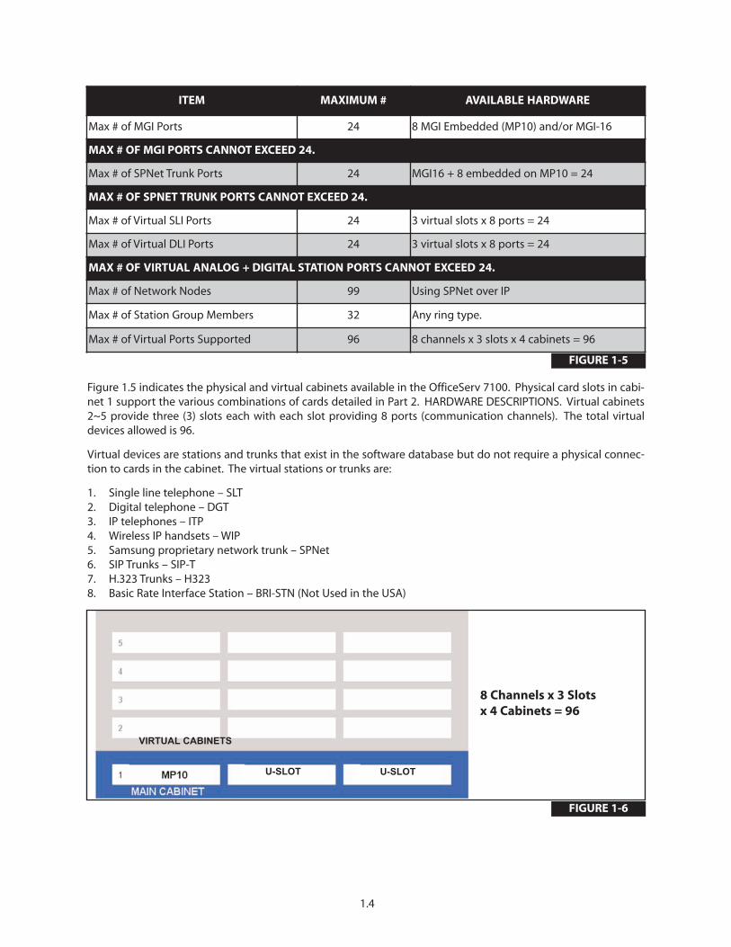
Figure 1.5 indicates the physical and virtual cabinets available in the OfficeServ 7100. Physical card slots in cabi-net 1 support the various combinations of cards detailed in Part 2. HARDWARE DESCRIPTIONS. Virtual cabinets2~5 provide three (3) slots each with each slot providing 8 ports (communication channels). The total virtualdevices allowed is 96.
Virtual devices are stations and trunks that exist in the software database but do not require a physical connec-tion to cards in the cabinet. The virtual stations or trunks are:
1. Single line telephone – SLT2. Digital telephone – DGT3. IP telephones – ITP4. Wireless IP handsets – WIP5. Samsung proprietary network trunk – SPNet6. SIP Trunks – SIP-T7. H.323 Trunks – H3238. Basic Rate Interface Station – BRI-STN (Not Used in the USA)
FIGURE 1-6
1.4
8 Channels x 3 Slots x 4 Cabinets = 96
U-SLOT U-SLOT
ITEM MAXIMUM # AVAILABLE HARDWARE
Max # of MGI Ports 24 8 MGI Embedded (MP10) and/or MGI-16
MAX # OF MGI PORTS CANNOT EXCEED 24.
Max # of SPNet Trunk Ports 24 MGI16 + 8 embedded on MP10 = 24
MAX # OF SPNET TRUNK PORTS CANNOT EXCEED 24.
Max # of Virtual SLI Ports 24 3 virtual slots x 8 ports = 24
Max # of Virtual DLI Ports 24 3 virtual slots x 8 ports = 24
MAX # OF VIRTUAL ANALOG + DIGITAL STATION PORTS CANNOT EXCEED 24.
Max # of Network Nodes 99 Using SPNet over IP
Max # of Station Group Members 32 Any ring type.
Max # of Virtual Ports Supported 96 8 channels x 3 slots x 4 cabinets = 96
FIGURE 1-5
VIRTUAL CABINETS

SAMPLE CONFIGURATIONTo better understand how the OfficeServ 7100 is configured, below is an example of a practical 4 x 12 configura-tion using a combination of digital and ITP telephones. Cabinet 1 shows the type of card installed in each phys-ical slot. Cabinets 2~5 show the default to the virtual assignments for each virtual slot. The IP telephones may beconnected to existing (external) data equipment or OfficeServ 7100 data module (4SWM) in a separate standalone cabinet.
Cabinet 1: Sample 4 x 12 Default Slot Configuration
VIRTUAL CABINET SLOT ASSIGNMENT
12 Stations and 4 Trunks
• 4 Analog Loop Trunks• 8 Digital Telephones• 4 IP Telephones• 4 MGI Channels (VoIP)• 4 Voice Mail Ports
FIGURE 1-7
1.5
(MGI-4)
(VM-4)
FIGURE 1-8

1.3 TECHNOLOGYMEMORYThe system operates using stored program control. This program is stored on a 256MB Multimedia Plus (MMC+)card inserted into the Main Processor card (MP10). The MMC+ card also provides space for a backup customerdatabase and voicemail storage. The customer database is stored indefinitely in NAND Flash. 2MB of SRAMbacked up by a super capacitor stores information such as Call Logs, Alarms, UCD call statistics, program logs andtraffic reports up to 24 hours without main system power.
MICROPROCESSORSOfficeServ 7100 uses distributed processing. Its primary processor is a M82511G (MP10), operating at a clockspeed of 375 MHz.This provides all the main processing necessary for the system. The tertiary level of processingis done in the keysets. The digital keysets use a Hitachi H8 processor for data communication within the system.
1.4 PROGRAMMINGThe OfficeServ 7100 is a self-configuring system. This means that immediately after applying power, theOfficeServ 7100 reads the types and locations of all installed interface cards and keysets and assigns default datato them. This data provides for system operation within a few minutes after applying power. All trunks and sta-tions are assigned three digit numbers according to the default numbering plan. This numbering plan is flexibleand may be changed to suit customer requirements. The installing technician customizes this default data tomeet the end user’s requirements.The system comes up default in a 4 CO line by 8 station squared configuration,with Caller ID enabled and 4 ports of voicemail/auto attendant.
The OfficeServ 7100 also provides a proprietary application called Installation Tool (IS Tool). This application canbe loaded onto any high performance PC (that meets the minimum requirements) and it is used only to programthe telephone system from anywhere in the world, provided there is a LAN/WAN or modem connection.
This permits technicians to program the phone system, modify the customer database or download (save) theentire customer database to a file. This file can be saved as a back up and can be uploaded when required torestore the database. The IS Tool can also be used to view the customer database offline, and to send new loadsof software upgrades to the MMC+ of a live system.
The system can be programmed from any IP or digital two line display keyset without interrupting system oper-ation.There are three levels of programming: technician ,customer and station.The technician level has access toall programs and can allow the customer access to system programs as needed. Technician and customer accesslevels are controlled by a different security pass codes and access procedure.
The OfficeServ 7100 provides a proprietary Web based program called Web Management for programmingembedded voicemail/AA. It allows programming from any where in the world provided there is a LAN/WAN con-nection to the MP10. The Web Management program runs on a Web Server and uses Internet Explorer V6.0 as itsinterface. This permits a technician to program the voicemail/AA using a personal computer. Use WebManagement on-site to modify the customer database (VM/AA only) or to download (save) the entire customerdatabase (VM/AA only).Through the use of LAN or WAN connection, an PC can access the OfficeServ 7100 systemremotely (off-site) to make database changes or perform uploads or downloads of the customer database as ifthe technician were on-site.
1.5 MIGRATION TO OfficeServ 7200 or OfficeServ 7400For businesses using the OfficeServ 7100, Samsung provides a convenient, easy and affordable migration path tothe larger OfficeServ 7200 or OfficeServ 7400 systems. Most of the keysets can become part of a much largerOfficeServ 7000 system. Features and operation are the same so there is no need to retrain users. See theOfficeServ 7200 or OfficeServ 7400 General Description for more details.
1.6

2.1
PART 2. HARDWARE DESCRIPTIONS
2.1 SYSTEM CABINETThe OfficeServ 7100 cabinet has three slots to mount boards, an AC to DC power supply, cooling fan, a batterybackup connector and power on/off switch. The cabinet is designed to be rack mounted in a 19 inch rack, wall-mounted with a wall-mounted bracket or placed on a table top. Slot 0 is exclusively used for the MP10 processorcard, and slots 1 and 2 are 64 channel universal slots that the UNI cards or other OfficeServ 7200/OfficeServ 7400station/trunk cards can be installed in.
2.2 PROCESSOR CARDSMP10 (MAIN PROCESSOR CARD)This is the main processor controlling system operation. The MP10 always goes in slot 0 of the main cabinet. TheMP10 provides a LAN connection, a MISC port (external page, MOH/BGM, loud/common bell), an SIO port(Samsung Maintenance Only), four universal ports for either digital phones or power of Ethernet ports (dependanton the type of daughterboard module plugged in), a internal modem slot, and a multimedia card (MMC+) slot whichcan accommodate a 256MB card containing the system software.The MP10 also includes embedded AutomatedAttendant,Voicemail, and MGI channels (license key required). The MP10 card cannot migrate to the OfficeServ 7200or OfficeServ 7400 systems.
The MP10 have a connector for mounting either a 4DLM card or a 4SWM card. When the 4DLM card is installedon the processor it will provide an interface for 4 Digital telephone sets. When the 4SWM card is installed on theprocessor it will provide an interface for 4 power over ethernet (POE) ports. The MP10 also has a connector formounting the optional modem board. This modem board can be used for remote access to system administra-tion at installation that do not have a LAN or WAN connection. This is the same modem card used in the otherOfficeServ systems. If the 4SWM is installed the switch and LAN is automatically connected by way of the back-plane. In addition it may be used as a backup for LAN connectivity.
2.2.1 EMBEDDED APPLICATIONS
VOICEMAIL/AUTO ATTENDANTThe MP10 processor has the voicemail and automated attendant application embedded onto the card.The VMAAis designed to meet the demands of the sophisticated voice mail user without sacrificing simplicity. TheAutomated Attendant is available with four ports for processing voicemail/AA traffic routed to the AutomatedAttendant.The same four ports can be enabled to perform both the voicemail and automated attendant functionof answering calls and storing messages into mailboxes for each extension.
MEDIA GATEWAY INTERFACEEight (8) MGI channels are embedded on the MP10 processor, and can be enabled (licensed in 1 port increments)to support VoIP functions such as IP phones, IP networking, and IP trunking. The embedded MGI channels can beenabled to support the following capabilities:
• IP Phones• IP Networking (Network multiple systems over an SPNet IP Network)*• G.729 CODEC, G.723.1, G.711, G.729A CODECs• IP Trunking (SIP/H.323)• T.38 Fax CODEC• Inband or Out-of-band signaling of DTMF tones
*The OfficeServ 7100 can network using QSig over PRI or SP-Net over IP to other Samsung OfficeServ systems.
Note: An additional 16 MGI channels can be added to the system if necessary by installing an MGI16 card.
The MP10 also provides various common resources (standard equipment) that are shared through the system.The MP10 provides the following: background music/music on hold audio inputs (radios, digital announcers, etc.),external paging audio output, loud bell audio output, common bell and programmable dry contact closures.Other common resources embedded on the MP10 are as follows:
• Two contact relays• Six 5 party conference circuits• Eight Caller ID sender/receivers• Eight DTMF receiver/transmitters• Eight MGI channels (Licensed IP phones, IP trunks and IP networking)• Four Voice Mail/Auto Attendant ports
2.2.2 MULTIMEDIA PLUSAn OfficeServ 7100 system must have a Multimedia Plus (MMC+) card installed in the main control processor(MP10) as the MMC+ card contains the system operating software. The MMC+ card can also be used to store abackup customer database and voicemail messages to supplement the database stored in the NAND Flash.
2.3 INTERFACE CARDS
UNI CARDThese cards provide the interface connections for telephone lines and stations to the KSU.These cards fit into theuniversal card slots to configure the system as required.
The UNI card can be installed in any of the two universal slots of the OfficeServ 7100 system.The UNI card is usedto accommodate other optional daughter boards. Any combination of the 4DLM, 4SLM or 4TRM modules can beinstalled in any of the three slots on the UNI card for a total of 12 ports per UNI card. This type of slot configura-tion allows the customers to grow or expand in 4 port increments. Customer can start out and configure the sys-tem as a 4 line by 8 station system and later expand to a 8 by 16 configuration and beyond.
Each slot can be used as a voice trunk line board or voice station board depending on the mounted option board.If a 4TRM option board is mounted in the UNI board, it operates as a voice trunk line board. If 4SLM and 4DLMoption boards are mounted, it operates as a voice station board. The UNI card is not hot swappable. This card cannot migrate to the OfficeServ 7200 or OfficeServ 7400 systems. See installation manual for details.
2.4 DAUGHTERBOARD CARDS
4DLMThis daughter board module is a four circuit digital station interface card that provides 1B+D service for the dif-ferent models of Samsung digital keyset. The 4DLM can be inserted in any of the three slots on the UNI card or on theMP10 card. See installation manual for details.
4SLMThis daughter board module is a four circuit analog station interface for industry standard single line telephonesthat require operation of an industry standard message waiting lamp with a voltage range of 85~96 VDC.The cardcan only be installed on the UNI card. The lamp can flash at a rate of 200ms to 500ms ON/OFF times. The 4SLMdoes not contain any over-voltage protection and is not qualified a OPX. It also does not contain DTMF receivers,
2.2
but instead shares the system DSP resources. The OfficeServ 7100 4SLM supports Caller ID to single line tele-phones. The 4SLM can only be inserted in any of the three slots on the UNI card. Each port on this card is intendedfor connection to one telephone. Connecting multiple telephones to a port may result in incorrect operation ordamage to the card. See installation manual for details.
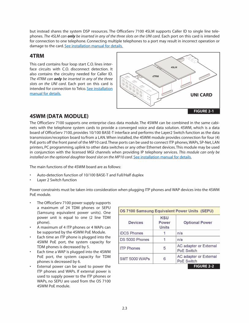
4TRMThis card contains four loop start C.O. lines inter-face circuits with C.O. disconnect detection. Italso contains the circuitry needed for Caller ID.The 4TRM can only be inserted in any of the threeslots on the UNI card. Each port on this card isintended for connection to Telco. See installationmanual for details.
4SWM (DATA MODULE) The OfficeServ 7100 supports one enterprise class data module. The 4SWM can be combined in the same cabi-nets with the telephone system cards to provide a converged voice and data solution. 4SWM, which is a databoard of OfficeServ 7100, provides 10/100 BASE-T interface and performs the Layer2 Switch function as the datatransmission/reception board to/from a LAN. When installed, the 4SWM module provides connection for four (4)PoE ports off the front panel of the MP10 card.These ports can be used to connect ITP phones,WAPs, SP-Net, LANprinters, PC programming, uplink to other data switches or any other Ethernet devices. This module may be usedin conjunction with the licensed MGI channels when providing IP telephony services. This module can only beinstalled on the optional daughter board slot on the MP10 card. See installation manual for details.
The main functions of the 4SWM board are as follows:
• Auto-detection function of 10/100 BASE-T and Full/Half duplex• Layer 2 Switch function
Power constraints must be taken into consideration when plugging ITP phones and WAP devices into the 4SWMPoE module.
• The OfficeServ 7100 power supply supportsa maximum of 24 TDM phones or SEPU(Samsung equivalent power units). Onepower unit is equal to one (2 line TDMphone).
• A maximum of 4 ITP phones or 4 WAPs canbe supported by the 4SWM PoE Module.
• Each time an ITP phone is plugged into the4SWM PoE port, the system capacity forTDM phones is decreased by 5.
• Each time a WAP is plugged into the 4SWMPoE port, the system capacity for TDMphones is decreased by 6.
• External power can be used to power theITP phones and WAPs. If external power isused to supply power to the ITP phones orWAPs, no SEPU are used from the OS 71004SWM PoE module.
2.3
FIGURE 2-1
UNI CARD
FIGURE 2-2
2.5 OfficeServ 7200/OfficeServ 7400 TRUNK CARDS
8TRK BOARD This card contains eight loop start C.O. line interface circuits with C.O. disconnect detection. It also contains thecircuitry needed for Caller ID. It can be inserted in any universal card slot in all cabinets. The 8TRK card is not hotswappable.
TEPRI/TEPRIa DIGITAL TRUNK BOARDThe card can be programmed as a PRI and will provide 23 bearer channels and 1 data channel (23B+D). This cardcan be installed in any universal slot in any OfficeServ 7100 cabinet.This card is also used for networking to othersystems (QSig/PRI networking)*. Add as many as required.T1 is not supported on this card in the OfficeServ 7100.The TEPRI/TEPRIa is not hot swappable.
2.6 OfficeServ 7200/OfficeServ 7400 VoIP CARDS
MGI-16 (MEDIA GATEWAY INTERFACE)The MGI-16 card supports 16 VoIP channels. The MGI-16 supports the following capabilities:
• IP Phones• IP Networking (Network multiple systems over an IP Network)*• G.729 (8K) CODEC, G.723.1, G.711, G.729A CODECs• IP Trunking (SIP/H.323)• T.38 Fax CODEC• Inband or Out-of-band signaling of DTMF tones• 801.1p, 802.1q (VLAN), QoS
2.7 OfficeServ 7200/OfficeServ 7400 STATION CARDS
8DLIThis card is an eight circuit digital station interface card that provides 1B+D service when installed in any univer-sal card slot in all cabinets.The KDB-D/S keyset daughter boards will not work when connected to this card in theOfficeserv 7100. The 8DLI card is not hot swappable.
16DLI2This card is a sixteen circuit digital station interface card that provides 1B+D service when installed in any univer-sal card slot in all cabinets.The KDB-D/S keyset daughter boards will not work when connected to this card in theOfficeServ 7100. The 16DLI2 card is not hot swappable
8SLIThis card is a eight circuit analog station interface for industry standard single line telephones or other analogperipheral devices.The 8SLI does not contain any over-voltage protection and is not qualified as OPX. It also doesnot contain DTMF receivers, but shares system DSP resources. It can be inserted in any universal card slot in allcabinets. Each port on this card is intended for connection to one telephone. Connecting multiple telephones toa port may result in incorrect operation or damage to the card.This card supports Power Fail Transfer feature. Seethe installation manual for details. The OfficeServ 7100 supports Caller ID to single line telephones.The 8SLI is nothot swappable.
2.4
16MWSLIThis card is a sixteen circuit analog station interface for industry standard single line telephones that require oper-ation of an industry standard message waiting lamp with a voltage range of 85 ~ 96 VDC. The lamp can be pro-grammed to be on continuously or flash at a programmable rate of 100ms to 2000ms ON/OFF times. The16MWSLI does not contain any over-voltage protection and is not qualified as OPX. It also does not contain DTMFreceivers, but instead shares the system DSP resources. It can be inserted in any universal card slot in all cabinets.Each port on this card is intended for connection to one telephone. Connecting multiple telephones to a portmay result in incorrect operation or damage to the card. This card supports the Power Fail Transfer feature. Seeinstallation manual for details. The OfficeServ 7100 supports Caller ID to single line telephones. The 16MWSLI isnot hot swappable.
8COMBOThis card has a combination of eight dedicated digital stations ports (1B+D) for Samsung Digital Keysets andeight dedicated analog station ports for industry standard single line telephones or other analog devices. Thiscard installs in any universal slot in any cabinet. The OfficeServ 7100 supports Caller ID to single line telephones.The 8COMBO is not hot swappable.
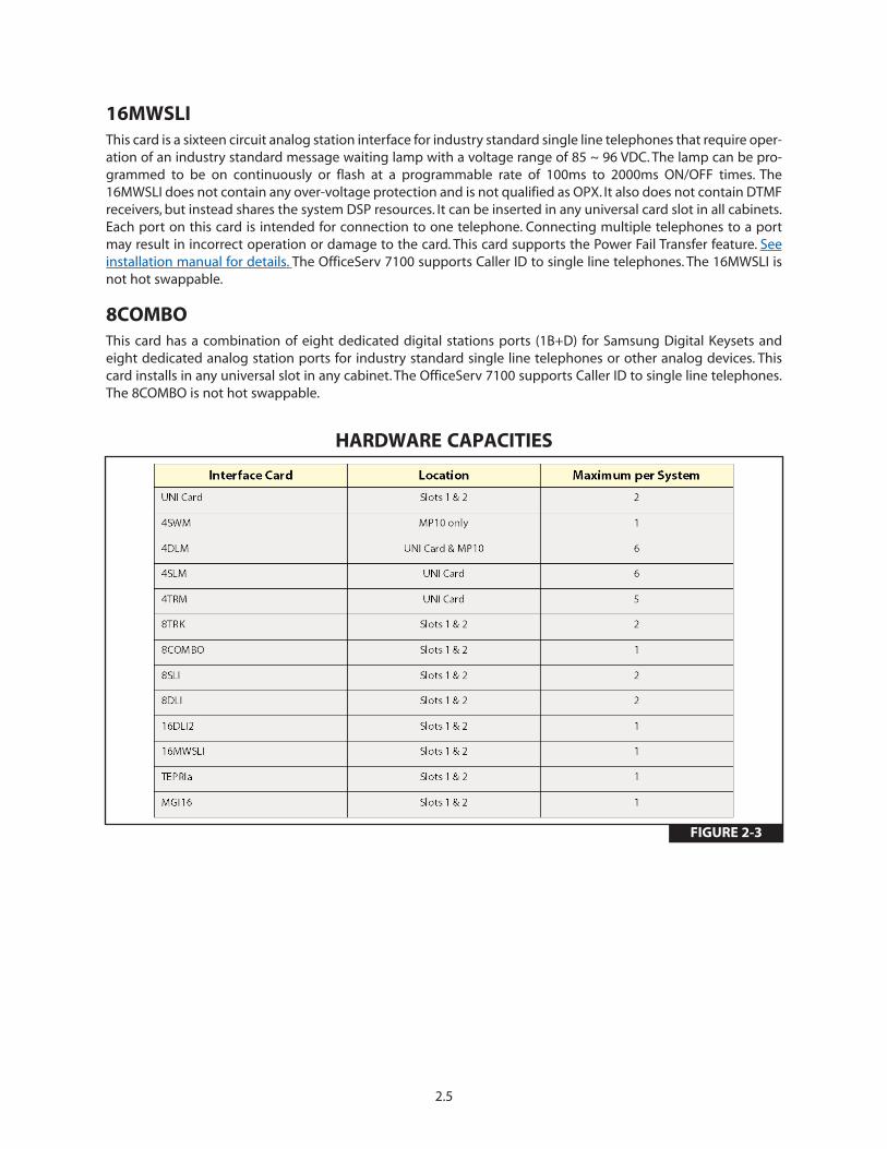
HARDWARE CAPACITIES
FIGURE 2-3
2.5

2.6
2.8 STATION EQUIPMENT
2.8.1 DS 5000 SERIES EQUIPMENT
DS 5021D KEYSET (See Figure 2–4)
• 32 character display (2 x 16) with three associated softkeys and a scroll key
• 21 programmable keys with tri-colored lights• Five fixed function keys• Terminal Status Indicator• Built-in speakerphone• Optional Full Duplex speakerphone module• Eight selectable ring tones• UP/DOWN buttons for digital control of speaker, handset
and ringer volumes• Desk- or wall-mounted
DS 5014D KEYSET (See Figure 2–5)
• 32 character display (2 x 16) with three associated softkeys and a scroll key
• 14 programmable keys with tri-colored lights• Five fixed function keys• Terminal Status Indicator• Built-in speakerphone• Optional Full Duplex speakerphone module• Eight selectable ring tones• UP/DOWN buttons for digital control of speaker, handset
and ringer volumes• Desk- or wall-mounted
DS 5007S KEYSET (see Figure 2–6)
• 32 character display (2 x 16) with three associated softkeys and a scroll key
• 7 programmable keys with tri-colored lights• Five fixed function keys• Terminal Status Indicator• Built-in speakerphone• Eight selectable ring tones• UP/DOWN buttons for digital control of speaker, handset
and ringer volumes• Desk- or wall-mounted
Note: The KDB-D and KDB-S Keyset daughter boards cannot be used with any keysets on the OfficeServ 7100.Only the KDB-F (full duplex) daughter boards can be used on the OfficeServ 7100.
FIGURE 2-4
FIGURE 2-5
FIGURE 2-6

DS 5064B AOM (See Figure 2–7) • 64 programmable keys with red lights• A maximum of 2 can be assigned to any keyset
to provide additional programmable keys• A maximum of 4 per system
Note: This AOM can be used with an IP keyset. Thecosmetic design matches both the DS-5000 and ITP-5100 keysets. A DLI port is required for this AOM.
DS 5021D KDB-F (FULL DUPLEX)This is a daughter board that can be installed only in the DS 5021D and DS 5014D keysets.The standard speaker-phone mode of operation for a DS keyset is half duplex. This means that you cannot transmit and receive speechat the same time. Adding a KDB-F to your keyset will convert the speakerphone into a full duplex mode enhanc-ing its operation. The KDB-F does not require a second “B” channel. In addition, the KDB-F may have up to three(3) external microphones attached to it for conference room type applications. The microphones require an“EXTMIC” key programmed on the keyset to activate or deactivate them.
Note: Only one KDB-F can be installed on a DS 5021D or DS 5014D keyset.The KDB-D/S modules are not support-ed on the iDCS and DS keysets on the OfficeServ 7100 system.
2.7
FIGURE 2-7
2.8.2 iDCS SERIES EQUIPMENT
iDCS 28D KEYSET (See Figure 2–8)
• 32 character display (2 x 16) with three associated soft keys anda scroll key
• 28 programmable keys with tri-colored lights• Four fixed function keys• Terminal Status Indicator• Built-in speakerphone• Optional full duplex speakerphone module• Eight selectable ring tones• UP/DOWN buttons for digital control of speaker, handset and
ringer volumes• Desk- or wall-mounted• Available in dark gray
iDCS 18D KEYSET (See Figure 2–9)
• 32 character display (2 x 16) with three associated soft keys anda scroll key
• 18 programmable keys with tri-colored lights• Four fixed function keys• Terminal Status Indicator• Built-in speakerphone• Optional full duplex speakerphone module• Eight selectable ring tones• UP/DOWN buttons for digital control of speaker, handset and
ringer volumes• Desk- or wall-mounted• Available in dark gray
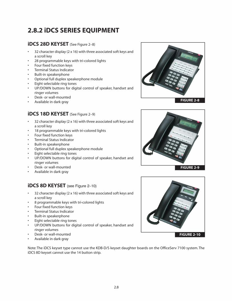
iDCS 8D KEYSET (see Figure 2–10)
• 32 character display (2 x 16) with three associated soft keys anda scroll key
• 8 programmable keys with tri-colored lights• Four fixed function keys• Terminal Status Indicator• Built-in speakerphone• Eight selectable ring tones• UP/DOWN buttons for digital control of speaker, handset and
ringer volumes• Desk- or wall-mounted• Available in dark gray
Note: The iDCS keyset type cannot use the KDB-D/S keyset daughter boards on the OfficeServ 7100 system. TheiDCS 8D keyset cannot use the 14 button strip.
2.8
FIGURE 2-8
FIGURE 2-9
FIGURE 2-10
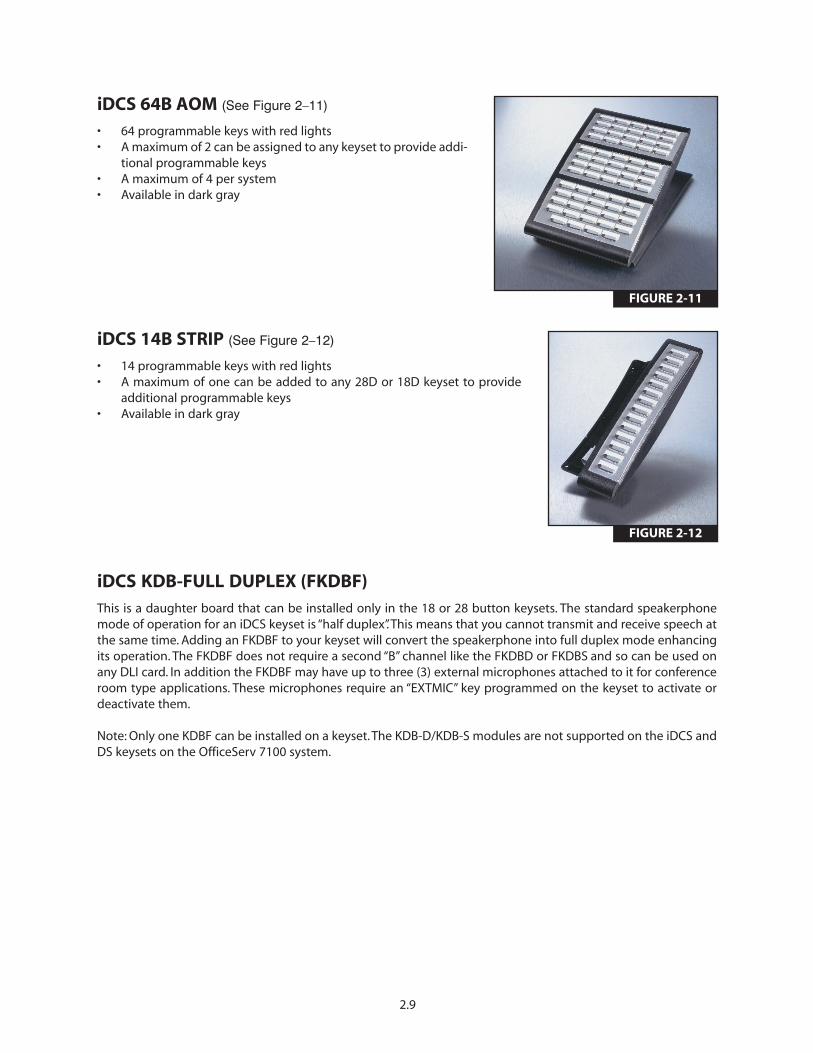
iDCS 64B AOM (See Figure 2–11)
• 64 programmable keys with red lights• A maximum of 2 can be assigned to any keyset to provide addi-
tional programmable keys• A maximum of 4 per system• Available in dark gray
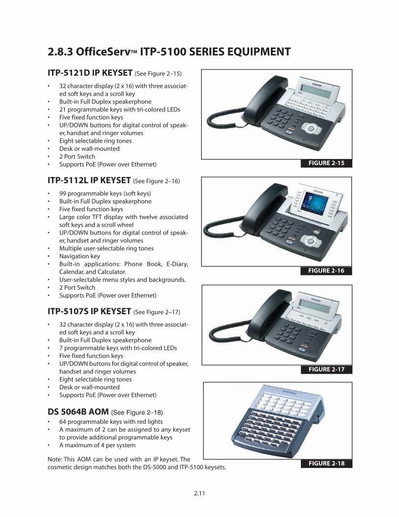
iDCS 14B STRIP (See Figure 2–12)
• 14 programmable keys with red lights• A maximum of one can be added to any 28D or 18D keyset to provide
additional programmable keys• Available in dark gray
iDCS KDB-FULL DUPLEX (FKDBF) This is a daughter board that can be installed only in the 18 or 28 button keysets. The standard speakerphonemode of operation for an iDCS keyset is “half duplex”. This means that you cannot transmit and receive speech atthe same time. Adding an FKDBF to your keyset will convert the speakerphone into full duplex mode enhancingits operation. The FKDBF does not require a second “B” channel like the FKDBD or FKDBS and so can be used onany DLI card. In addition the FKDBF may have up to three (3) external microphones attached to it for conferenceroom type applications. These microphones require an “EXTMIC” key programmed on the keyset to activate ordeactivate them.
Note: Only one KDBF can be installed on a keyset. The KDB-D/KDB-S modules are not supported on the iDCS andDS keysets on the OfficeServ 7100 system.
2.9
FIGURE 2-11
FIGURE 2-12

2.10
DOOR PHONE INTERFACE MODULE (DPIM) & DOOR PHONE (see Figures 2–13 and 2–14)
• The DPIM adapts any DLI circuit for use with the door phone unit• Commonly used to request entry through locked doors (interior or exterior) or as a room monitoring box• Provides contact control to be used with customer-provided electric door lock• Door phone is wall-mounted• Door phone is weather resistant
FIGURE 2-14FIGURE 2-13
2.11
2.8.3 OfficeServ™ ITP-5100 SERIES EQUIPMENT
ITP-5121D IP KEYSET (See Figure 2–15)
• 32 character display (2 x 16) with three associat-ed soft keys and a scroll key
• Built-in Full Duplex speakerphone• 21 programmable keys with tri-colored LEDs• Five fixed function keys• UP/DOWN buttons for digital control of speak-
er, handset and ringer volumes• Eight selectable ring tones• Desk or wall-mounted• 2 Port Switch• Supports PoE (Power over Ethernet)
ITP-5112L IP KEYSET (See Figure 2–16)
• 99 programmable keys (soft keys)• Built-in Full Duplex speakerphone• Five fixed function keys• Large color TFT display with twelve associated
soft keys and a scroll wheel• UP/DOWN buttons for digital control of speak-
er, handset and ringer volumes• Multiple user-selectable ring tones• Navigation key• Built-in applications: Phone Book, E-Diary,
Calendar, and Calculator.• User-selectable menu styles and backgrounds.• 2 Port Switch• Supports PoE (Power over Ethernet)
ITP-5107S IP KEYSET (See Figure 2–17)
• 32 character display (2 x 16) with three associat-ed soft keys and a scroll key
• Built-in Full Duplex speakerphone• 7 programmable keys with tri-colored LEDs• Five fixed function keys• UP/DOWN buttons for digital control of speaker,
handset and ringer volumes• Eight selectable ring tones• Desk or wall-mounted• Supports PoE (Power over Ethernet)
DS 5064B AOM (See Figure 2–18) • 64 programmable keys with red lights• A maximum of 2 can be assigned to any keyset
to provide additional programmable keys• A maximum of 4 per system
Note: This AOM can be used with an IP keyset. Thecosmetic design matches both the DS-5000 and ITP-5100 keysets.
FIGURE 2-17
FIGURE 2-18
FIGURE 2-16
FIGURE 2-15

2.12
2.8.4 OfficeServ™ SOFTPHONESamsung OfficeServ™ Softphone is a software-based application that turns your computer into a full-featuredSamsung IP telephone. It is installed directly onto your laptop or desktop PC running Microsoft Windows XP or2000 operating system. Once a USB headset or a USB handset is connected; the Softphone delivers virtually iden-tical functionality as the ITP-5112 L and ITP-5121D desktop ITP phones.
OfficeServ™ Softphone is ideal for telecommuter and mobile users. Remote workers can simply connect theirlaptop to the corporate network, snap in a USB headset, and function as if they were in their own office. They canplace, receive, and handle calls on both the internal and external network, providing a truly portable and practi-cal solution.
2.8.5 OfficeServ™ Wireless
WIRELESS LAN ACCESS POINT (SMT-R2000) (See Figure 2–19)
The wireless access point (SMT-R2000) provideswireless coverage throughout a building and sur-rounding areas. It supports IEEE 802.11a/b/g WLANstandard for both voice and data. It gives priority tovoice packets. The quality of the service for voice isalways guaranteed.
Highlights of SMT-R2000 Features• Two radios. Radio 1: 5GHz IEEE 802.11a (54 Mbps) and Radio 2: 2.4 GHz IEEE 802.11b/g (54 Mbps)• 8 voice calls per Access Point.• Wireless data stations or handsets association per AP, 802.11a: 255, 802.11b/g: 255. Total: 32• Wireless Access Point or repeater mode• RP-SMA type connector for external antenna• Router mode support• Enhanced security (WEP, WPA, WPA2, etc.)• QoS supports 802.1 p/q, DSCP, 802.11e (WMM), ToS• PoE (Power over Ethernet) support or External Power Adapter (supplied)• Easy Web Management• Wi-Fi certified• No MGI channel required for conversation between handset to handset or handset to ITP desktop phone
FIGURE 2-19
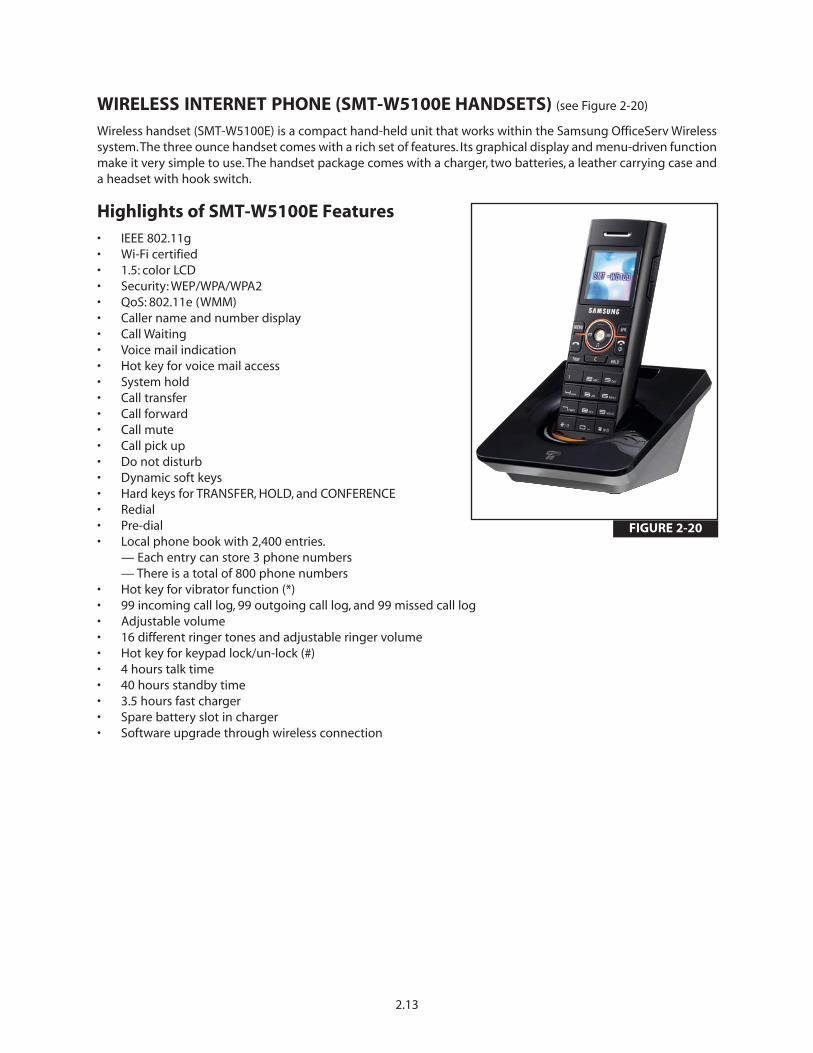
WIRELESS INTERNET PHONE (SMT-W5100E HANDSETS) (see Figure 2-20)
Wireless handset (SMT-W5100E) is a compact hand-held unit that works within the Samsung OfficeServ Wirelesssystem.The three ounce handset comes with a rich set of features. Its graphical display and menu-driven functionmake it very simple to use. The handset package comes with a charger, two batteries, a leather carrying case anda headset with hook switch.
Highlights of SMT-W5100E Features• IEEE 802.11g• Wi-Fi certified• 1.5: color LCD• Security: WEP/WPA/WPA2• QoS: 802.11e (WMM)• Caller name and number display • Call Waiting • Voice mail indication • Hot key for voice mail access • System hold • Call transfer • Call forward • Call mute • Call pick up • Do not disturb • Dynamic soft keys • Hard keys for TRANSFER, HOLD, and CONFERENCE • Redial • Pre-dial • Local phone book with 2,400 entries.
— Each entry can store 3 phone numbers — There is a total of 800 phone numbers
• Hot key for vibrator function (*) • 99 incoming call log, 99 outgoing call log, and 99 missed call log • Adjustable volume • 16 different ringer tones and adjustable ringer volume • Hot key for keypad lock/un-lock (#) • 4 hours talk time • 40 hours standby time • 3.5 hours fast charger • Spare battery slot in charger • Software upgrade through wireless connection
2.13
FIGURE 2-20

PART 3. SPECIFICATIONS
3.1 ELECTRICAL SPECIFICATIONS
POWER SUPPLY UNITThe Power Supply Unit (PSU) is installed in the cabinet of the OfficeServ 7100. The PSU supplies the power of -48 V DC received from the external battery backup power supply unit to each board. The rating is as follows.
• INPUT RATING: 100-120 VAC; 2A; 50/60 Hz or DC -48 V, 3A
The specifications of the power I/O are shown in the table below.
3.2 DIMENSIONS
Note: When the cabinets are rack mounted, the rack mount bracket will add some height to the system.
3.1
3.1a I/O VOLTAGE of the PSU
PSU (OfficeServ 7100)
Input Voltage100-120 VAC ~ 2A 50/60 HzDC -48V ~ 3A (Battery Backup)
Output Voltage
DC -54V, 1.1A
DC +5V, 5.0A
DC -5.3V, 0.3A
DC +3.3V, 5A
DC +12V, 0.4A
DC -54.0V, 0.25A (Battery Backup)
Maximum Power Consumption/PSU 105 W
HEIGHT WIDTH DEPTH
OfficeServ 7100 Main Cabinet 3.11” 17.32” 16”
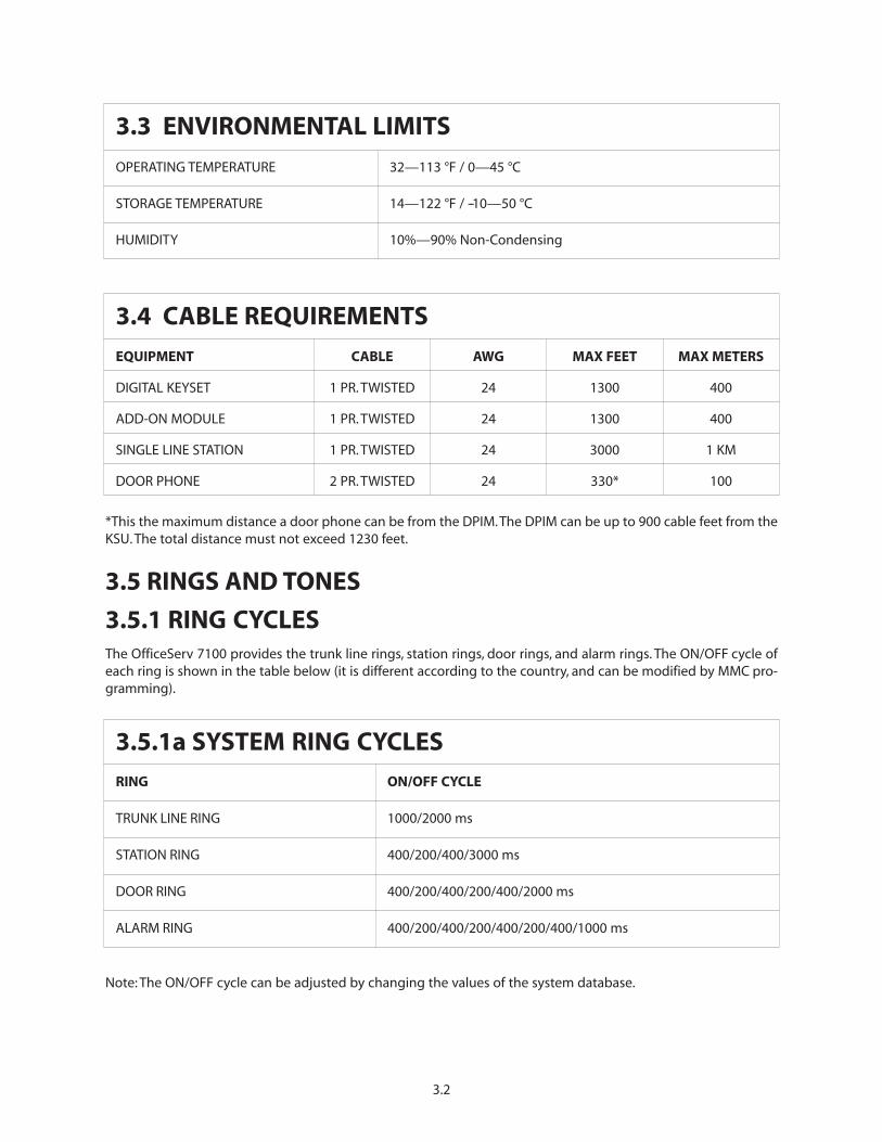
*This the maximum distance a door phone can be from the DPIM.The DPIM can be up to 900 cable feet from theKSU. The total distance must not exceed 1230 feet.
3.5 RINGS AND TONES
3.5.1 RING CYCLESThe OfficeServ 7100 provides the trunk line rings, station rings, door rings, and alarm rings. The ON/OFF cycle ofeach ring is shown in the table below (it is different according to the country, and can be modified by MMC pro-gramming).
Note: The ON/OFF cycle can be adjusted by changing the values of the system database.
3.2
3.3 ENVIRONMENTAL LIMITS
OPERATING TEMPERATURE 32—113 °F / 0—45 °C
STORAGE TEMPERATURE 14—122 °F / --10—50 °C
HUMIDITY 10%—90% Non-Condensing
3.4 CABLE REQUIREMENTS
EQUIPMENT CABLE AWG MAX FEET MAX METERS
DIGITAL KEYSET 1 PR. TWISTED 24 1300 400
ADD-ON MODULE 1 PR. TWISTED 24 1300 400
SINGLE LINE STATION 1 PR. TWISTED 24 3000 1 KM
DOOR PHONE 2 PR. TWISTED 24 330* 100
3.5.1a SYSTEM RING CYCLES
RING ON/OFF CYCLE
TRUNK LINE RING 1000/2000 ms
STATION RING 400/200/400/3000 ms
DOOR RING 400/200/400/200/400/2000 ms
ALARM RING 400/200/400/200/400/200/400/1000 ms
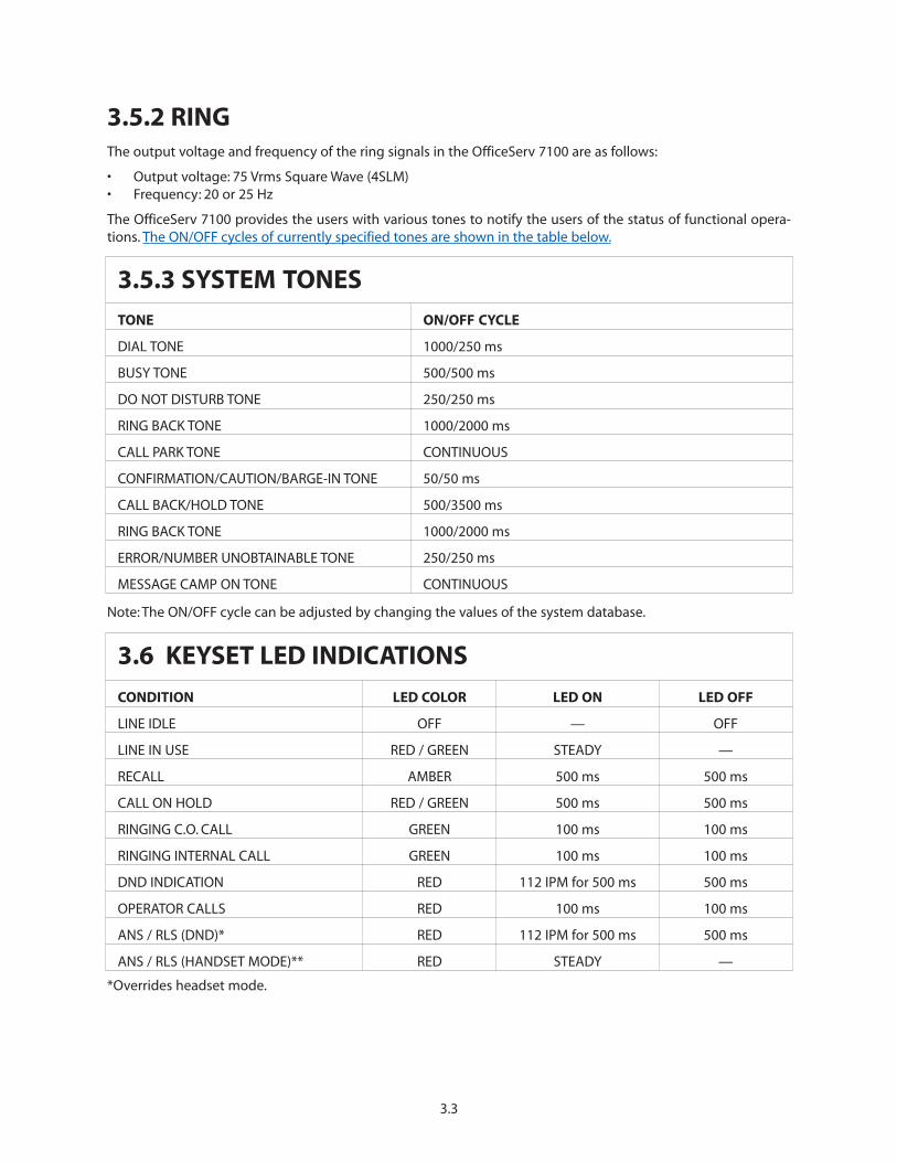
3.5.2 RINGThe output voltage and frequency of the ring signals in the OfficeServ 7100 are as follows:
• Output voltage: 75 Vrms Square Wave (4SLM)• Frequency: 20 or 25 Hz
The OfficeServ 7100 provides the users with various tones to notify the users of the status of functional opera-tions. The ON/OFF cycles of currently specified tones are shown in the table below.
Note: The ON/OFF cycle can be adjusted by changing the values of the system database.
*Overrides headset mode.
3.3
3.5.3 SYSTEM TONES
TONE ON/OFF CYCLE
DIAL TONE 1000/250 ms
BUSY TONE 500/500 ms
DO NOT DISTURB TONE 250/250 ms
RING BACK TONE 1000/2000 ms
CALL PARK TONE CONTINUOUS
CONFIRMATION/CAUTION/BARGE-IN TONE 50/50 ms
CALL BACK/HOLD TONE 500/3500 ms
RING BACK TONE 1000/2000 ms
ERROR/NUMBER UNOBTAINABLE TONE 250/250 ms
MESSAGE CAMP ON TONE CONTINUOUS
3.6 KEYSET LED INDICATIONS
CONDITION LED COLOR LED ON LED OFF
LINE IDLE OFF — OFF
LINE IN USE RED / GREEN STEADY —
RECALL AMBER 500 ms 500 ms
CALL ON HOLD RED / GREEN 500 ms 500 ms
RINGING C.O. CALL GREEN 100 ms 100 ms
RINGING INTERNAL CALL GREEN 100 ms 100 ms
DND INDICATION RED 112 IPM for 500 ms 500 ms
OPERATOR CALLS RED 100 ms 100 ms
ANS / RLS (DND)* RED 112 IPM for 500 ms 500 ms
ANS / RLS (HANDSET MODE)** RED STEADY —
3.4
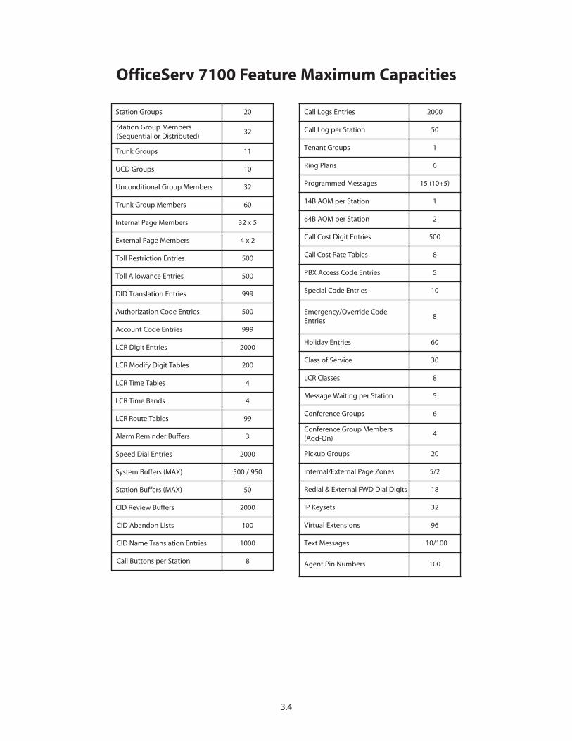
Station Groups 20
Station Group Members(Sequential or Distributed)
32
Trunk Groups 11
UCD Groups 10
Unconditional Group Members 32
Trunk Group Members 60
Internal Page Members 32 x 5
External Page Members 4 x 2
Toll Restriction Entries 500
Toll Allowance Entries 500
DID Translation Entries 999
Authorization Code Entries 500
Account Code Entries 999
LCR Digit Entries 2000
LCR Modify Digit Tables 200
LCR Time Tables 4
LCR Time Bands 4
LCR Route Tables 99
Alarm Reminder Buffers 3
Speed Dial Entries 2000
System Buffers (MAX) 500 / 950
Station Buffers (MAX) 50
CID Review Buffers 2000
CID Abandon Lists 100
CID Name Translation Entries 1000
Call Buttons per Station 8
OfficeServ 7100 Feature Maximum Capacities
Call Logs Entries 2000
Call Log per Station 50
Tenant Groups 1
Ring Plans 6
Programmed Messages 15 (10+5)
14B AOM per Station 1
64B AOM per Station 2
Call Cost Digit Entries 500
Call Cost Rate Tables 8
PBX Access Code Entries 5
Special Code Entries 10
Emergency/Override CodeEntries
8
Holiday Entries 60
Class of Service 30
LCR Classes 8
Message Waiting per Station 5
Conference Groups 6
Conference Group Members(Add-On)
4
Pickup Groups 20
Internal/External Page Zones 5/2
Redial & External FWD Dial Digits 18
IP Keysets 32
Virtual Extensions 96
Text Messages 10/100
Agent Pin Numbers 100
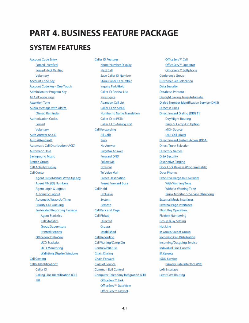
Account Code Entry
Forced - Verified
Forced - Not Verified
Voluntary
Account Code Key
Account Code Key - One Touch
Administrator Program Key
All Call Voice Page
Attention Tone
Audio Message with Alarm
(Timer) Reminder
Authorization Codes
Forced
Voluntary
Auto Answer on CO
Auto Attendant†
Automatic Call Distribution (ACD)
Automatic Hold
Background Music
Branch Group
Call Activity Display
Call Center
Agent Busy/Manual Wrap-Up Key
Agent PIN (ID) Numbers
Agent Login & Logout
Automatic Logout
Automatic Wrap-Up Timer
Priority Call Queuing
Embedded Reporting Package
Agent Statistics
Call Statistics
Group Supervisors
Printed Reports
OfficeServ DataView
UCD Statistics
UCD Monitoring
Wall-Style Display Windows
Call Costing
Caller Identification†
Caller ID
Calling Line Identification (CLI)
PRI
Caller ID Features
Name/Number Display
Next Call
Save Caller ID Number
Store Caller ID Number
Inquire Park/Hold
Caller ID Review List
Investigate
Abandon Call List
Caller ID on SMDR
Number to Name Translation
Caller ID to PSTN
Caller ID to Analog Port
Call Forwarding
All Calls
Busy
No Answer
Busy/No Answer
Forward DND
Follow Me
External
To Voice Mail
Preset Destination
Preset Forward Busy
Call Hold
Exclusive
System
Remote
Call Park and Page
Call Pickup
Directed
Groups
Established
Call Recording
Call Waiting/Camp-On
Centrex/PBX Use
Chain Dialing
Chain Forward
Class of Service
Common Bell Control
Computer Telephony Integration (CTI)
OfficeServ™ Link
OfficeServ™ DataView
OfficeServ™ EasySet
OfficeServ™ Call
OfficeServ™ Operator
OfficeServ™ Softphone
Conference Group
Customer Set Relocation
Data Security
Database Printout
Daylight Saving Time-Automatic
Dialed Number Identification Service (DNIS)
Direct In Lines
Direct Inward Dialing (DID) T1
Day/Night Routing
Busy or Camp-On Option
MOH Source
DID Call Limits
Direct Inward System Access (DISA)
Direct Trunk Selection
Directory Names
DISA Security
Distinctive Ringing
Door Lock Release (Programmable)
Door Phones
Executive Barge-In (Override)
With Warning Tone
Without Warning Tone
Trunk Monitor or Service Observing
External Music Interfaces
External Page Interfaces
Flash Key Operation
Flexible Numbering
Group Busy Setting
Hot Line
In Group/Out of Group
Incoming Call Distribution
Incoming/Outgoing Service
Individual Line Control
IP Keysets
ISDN Service
Primary Rate Interface (PRI)
LAN Interface
Least Cost Routing
4.1
PART 4. BUSINESS FEATURE PACKAGE
SYSTEM FEATURES

Live System Programming
From any Display Keyset
With a Personal Computer
Meet Me Page and Answer
Memory Protection
Message Waiting Indications
Message Waiting Key
Microphone On/Off per Station
Mobility Solution
Multiple Language Support
Music on Hold—Flexible
Music on Hold—Sources
Networking
QSIG over IP
QSIG over PRI
Operator Group
Overflow
Operator
Station Group
Override Codes
Paging
Internal Zones (5)
External Zones (2)
All External
Page All
Park Orbits
Power over Ethernet (PoE)
Prime Line Selection
Priority Call Queuing
Private Lines
Programmable Line Privacy
Programmable Timers
Recalls
Recall to Operator
Redial Review
Remote Programming—PC
Ring Modes
Time Based Routing–Plans
Automatic / Manual
Holiday Schedule
Temporary Override
Ring Over Page
Secretary Pooling
Single Line Connections
Speed Dial Numbers
Station List
System List
Speed Dial by Directory
Station Hunt Groups
Distributed
Sequential
Unconditional
Station Message Detail Recording (SMDR)
Station Pair
System Alarms
System Maintenance Alarms
System Directory
Tenant Service
Toll Restriction
By Day or Night
By Line or Station
Eight Dialing Classes
Special Code Table
Toll Restriction Override
Tone or Pulse Dialing
Traffic Reporting
Transfer
Screened/Unscreened
Voice Mail Transfer Key
With Camp-On
Trunk Groups
Uniform Call Distribution (UCD)
Universal Answer
Virtual Extensions
Voice Mail
Inband Signalling
Embedded on MP10
VoIP
Walking Class of Service
Wireless Handsets—See Mobility Solution
4.2
†Requires optional hardware and/or software. Ask your dealer for details.
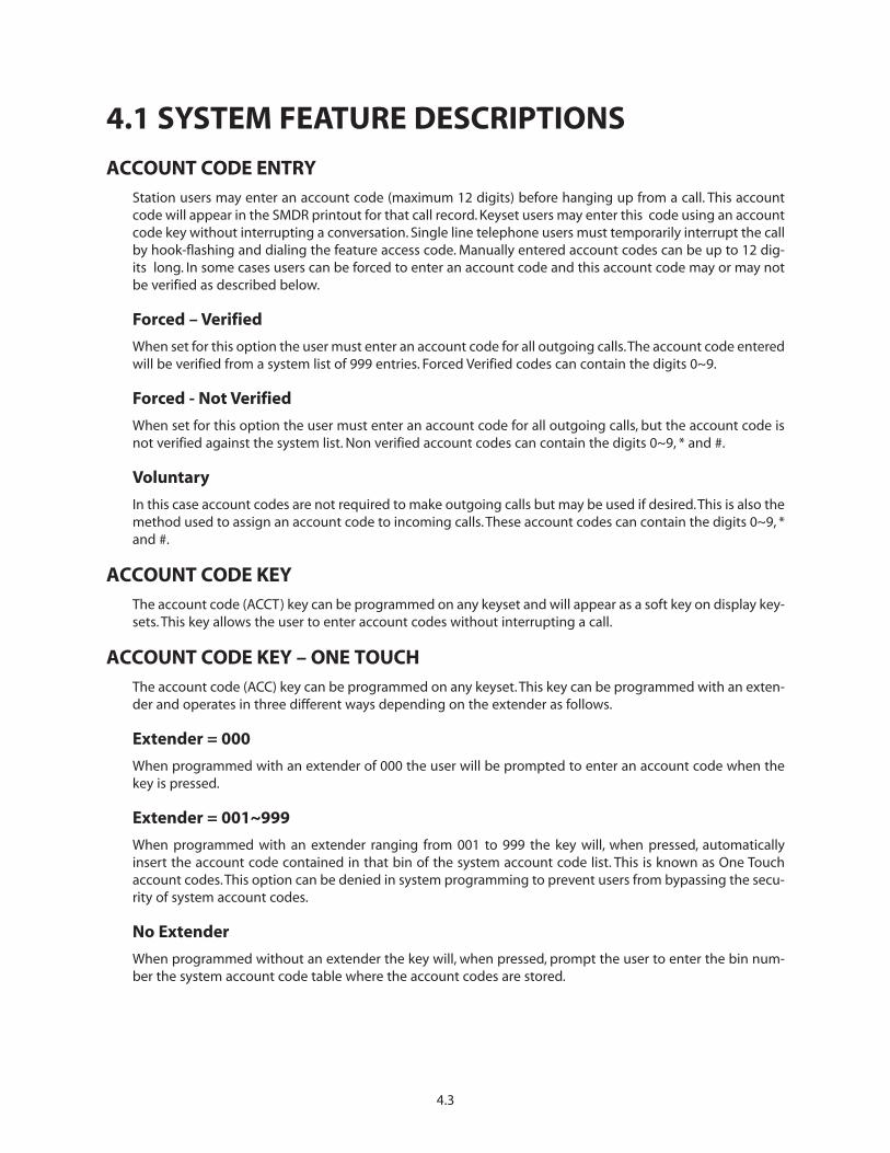
4.1 SYSTEM FEATURE DESCRIPTIONS
ACCOUNT CODE ENTRYStation users may enter an account code (maximum 12 digits) before hanging up from a call. This accountcode will appear in the SMDR printout for that call record. Keyset users may enter this code using an accountcode key without interrupting a conversation. Single line telephone users must temporarily interrupt the callby hook-flashing and dialing the feature access code. Manually entered account codes can be up to 12 dig-its long. In some cases users can be forced to enter an account code and this account code may or may notbe verified as described below.
Forced – Verified
When set for this option the user must enter an account code for all outgoing calls.The account code enteredwill be verified from a system list of 999 entries. Forced Verified codes can contain the digits 0~9.
Forced - Not Verified
When set for this option the user must enter an account code for all outgoing calls, but the account code isnot verified against the system list. Non verified account codes can contain the digits 0~9, * and #.
Voluntary
In this case account codes are not required to make outgoing calls but may be used if desired.This is also themethod used to assign an account code to incoming calls. These account codes can contain the digits 0~9, *and #.
ACCOUNT CODE KEYThe account code (ACCT) key can be programmed on any keyset and will appear as a soft key on display key-sets. This key allows the user to enter account codes without interrupting a call.
ACCOUNT CODE KEY – ONE TOUCHThe account code (ACC) key can be programmed on any keyset.This key can be programmed with an exten-der and operates in three different ways depending on the extender as follows.
Extender = 000
When programmed with an extender of 000 the user will be prompted to enter an account code when thekey is pressed.
Extender = 001~999
When programmed with an extender ranging from 001 to 999 the key will, when pressed, automaticallyinsert the account code contained in that bin of the system account code list. This is known as One Touchaccount codes.This option can be denied in system programming to prevent users from bypassing the secu-rity of system account codes.
No Extender
When programmed without an extender the key will, when pressed, prompt the user to enter the bin num-ber the system account code table where the account codes are stored.
4.3
ADMINISTRATOR PROGRAM KEYThis feature gives designated stations the ability to administer a number of System functions from their key-set using a assigned button. The Administrator Program (PROG) key is programmed in MMC 722. The stationpasscode must be changed from the default value to use this feature. See the System Administrator Guide formore information.
ALL CALL VOICE PAGEUsers can page internal zone zero and all external paging zones at the same time by dialing the All Page code.Keysets may be restricted from making or receiving pages in system programming. A maximum of 32 keysetscan be programmed in each internal page zone to receive page announcements.
Note: Each IP keyset being paged requires an MGI channel to carry the page audio. If all MGI channels arebusy then no IP keysets will receive a page.
ATTENTION TONETo get your attention, a brief tone precedes all page announcements and intercom voice calls.There are sep-arate programmable duration timers for page and voice announce tones.
AUDIO MESSAGE WITH ALARM (TIMER) REMINDER This feature provides an option that allows a recorded message to be played to a user when they go off hookto answer an alarm reminder ring (timed reminder ring). The message is recorded on the Samsung embed-ded voicemail. In addition, if the AA group is busy when the reminder call is answered the system will play adesignated MOH source to the user. Alternatively System programming can define an external music sourceto be played when the Appointment Reminder is answered.
AUTHORIZATION CODESAuthorization codes are used to give permission to make a call. A maximum of 500 four to ten-digit authori-zation codes can be either forced or voluntary.When used, authorization codes will automatically change thedialing station’s class of service to the level assigned to the authorization code. Authorization codes may beprogrammed to print or not print on SMDR.
Forced
When a station is programmed for forced authorization, the user must always enter this code before dialingis allowed. The dialed authorization code is verified from the system list of 500 authorization codes.
Voluntary
Any station user can always enter an authorization code before they begin dialing. The dialed authorizationcode is verified from a system list of 500 authorization codes.
AUTO ANSWER ON COAllows new CO calls directed to a certain keyset to auto answer and be in the call announce mode.This meansthat private lines and DID calls can be “auto answered” in the same manner as intercom calls.Transferred callsand calls to a station group of which that keyset is a member will continue to ring.
AUTO ATTENDANTThe Automated Attendant provides very powerful and extremely flexible Auto Attendant functionality. As itis embedded into the MP10 of the OfficeServ 7100 the Auto Attendant provides Customized interactive Callrouting for Public and Internal (Subscriber) callers.
4.4
The embedded Auto Attendant multi-level customizable Menu Trees. These Menu trees can be very simpleor as complex as needed for the application. Callers can be automatically routed based on CID, ANI, CLI, DNIS,and/or Trunk ID information received.
The Automated Attendant can handle up to 4 simultaneous callers.
There are professionally recorded prompts installed that help the caller navigate through the system andcustomizable prompts per system that can be added to personalize the application to an organization’s spe-cific needs.
AUTOMATIC CALL DISTRIBUTION (ACD)ACD is a call distribution method by which callers in a queue are routed to the next available agent. Whilewaiting in a queue a canned or customized announcement can be periodically played to the caller based ona programmable timer while retaining their place in the queue. Statistical and historical reports are availableto assist supervisors in managing a call center. See Call Center.
AUTOMATIC HOLDWhile a keyset user is engaged on an outside (C.O.) call, pressing another trunk key, route key or CALL buttonautomatically places the call on hold when Automatic Hold is enabled. Pressing TRSF, CONFERENCE, PAGE ora DSS key always automatically places a C.O. call on hold. Intercom calls can be automatically held only bypressing TRSF or CONFERENCE. Each keyset user can enable or disable Automatic Hold.
BACKGROUND MUSICKeyset users may choose to hear music through their keyset speakers when optional external sources areinstalled. Each user may adjust this level by the use of a volume control program at the selected keyset.
BRANCH GROUPThis feature allows stations included in a branch group to answer a ringing call to another station in thegroup by simply lifting the handset or going on speakerphone mode.This feature works well when there is aneed to answer calls for people who may be away from their desk or when a common answering pool isneeded. Calls can be directed to a common bell and then can be answered by anyone in the Branch Group.There are a total of 20 branch groups available, but a station can only be in one branch group.
CALL ACTIVITY DISPLAYThe OfficeServ 7100 will record and buffer all calling activity within the system. With a Call Activity Display(CAD) key, the OfficeServ 7100 will display a “snapshot” of the following information:
• The maximum number of ports that have been used• The maximum number of trunks that have been used• The maximum number of stations that have been used• The current number of ports in use• The current number of trunks in use• The current number of stations in use
CALL CENTERACD/UCD Call Centers are required when the user expects to have more ringing calls than people (agents) toanswer them. This functionality prevents callers from receiving busy signals or lengthy ring delays beforeanswering. Callers reaching a busy group with no available agents are held in queue for the next availableagent. First and second announcements reassure the caller until an agent becomes available. The OfficeServ
4.5
7100 can have 10 simultaneous ACD/UCD groups with a maximum of 32 agents per group using sequentialor distributed ring modes. Any time there are one or more calls in queue and no available agents, the longestwaiting call will automatically be distributed to the next available agent. When there are no calls in queuethe next new call will be routed to the next idle agent according to a specified distribution method.
There are two available reporting options to support the [system] call center functionality. The embeddedbasic reporting package included with the telephone system is ideal for small informal call center solutionsas it provides simple ASCII text reports to a customer provided LAN printer, as well as informational displaysat a supervisor’s display telephone. The more sophisticated call center may require the optional OfficeServDataView CTI application that provides historical reporting, agent and call monitoring and wallboard dis-plays.
NOTE: Some features require optional hardware or software. Ask your authorized Samsung Dealer for details.
Agent Busy / Manual Wrap-Up Key
This UCD group feature allows an agent to have a programmed button that when depressed will remove thekeyset from free status within the group.The agent can depress the button again to return the keyset to freestatus. This provides a method for agents to manually extend their wrap-up time when necessary. This alsoallows agents to perform other duties such as receiving or making telephone calls without having to log outof the group.
Agent PIN (ID) Numbers
When desired this feature allows agents to be assigned a PIN number to use when logging in and out of aUCD group.This allows an agent to move from location to location and retain their productivity records.Thereare a total of 300 PIN numbers available in the system.
Agent Login & Logout
At any time agents may login or out of a station call group by dialing an access code or simply pressing theIG button for the selected group. A red LED on the IG button indicates you are in the group.
Automatic Logout
This feature allows the system to further limit ringing delays by automatically logging out stations that areunattended. If a call is delivered to a station that does not answer after a programmable number of rings, thestation is automatically logged out of the group so that no further call attempts will be made until the agenthas logged back in.
Automatic Wrap-up Timer
The wrap-up timer prevents calls to an agent for a programmable period of time. This allows the agent to fin-ish up paper work associated with the last call.
Priority Call Queuing
This feature places calls to a station queue ahead of other calls based on priority level (1-9).The system com-pares the DID number, Caller ID, or trunk ID to a preprogrammed table and assigns the call a correspondingpriority that places it in the appropriate position in the queue. This functionality is ideal when specific cus-tomers require special treatment.
EMBEDDED REPORTING PACKAGEThe OfficeServ 7100 system provides some basic reports and statistics available to a supervisor using a dis-play keyset. These features can be used in conjunction with, or independently of, the OfficeServ™ DataViewreporting and monitoring package.
4.6

Agent Statistics
UCD supervisor positions using a display keyset can monitor the number of agents in a group and how manyagents are currently logged in. Each station’s status can be reviewed for the number of calls answered andthe average call length for the day.
Call Statistics
UCD supervisor positions using a display keyset can monitor the number of calls in queue, the longest waittime for calls currently in queue, the average wait time for the day, and the total number of calls answered forthe day.
Group Supervisors
Multiple supervisors can be assigned to each group and one station can be given supervisor status for mul-tiple UCD groups.The group supervisor (using a display keyset) can log agents in and out of the group in realtime to help manage the workload.
Printed Reports
UCD supervisor positions using a display keyset may run printed reports to a customer-provided printer,showing the data available from the supervisor displays. These reports can be run manually or scheduled torun at specific intervals.
OFFICESERV DATAVIEWFor users who require more power than the embedded reports can provide, the web-based OfficeServ™DataView CTI application can be used for enhanced reporting and monitoring functionality. See separateDataView Literature for more details.
UCD Statistics
OfficeServ™ DataView provides over a dozen different historical reports to provide detailed statistics on callvolume and call times as well as agent activity. Also included is a detailed Abandoned Call list to define eachlost call to the UCD group.
UCD Monitoring
OfficeServ™ DataView provides several different monitoring interfaces that allow users to easily see live con-nection status and port activity for UCD groups and agents.
Wallboard-Style Display Windows
OfficeServ™ DataView is equipped with a series of wallboard-style displays which allow quick and easy visi-bility of live call status information about the group, such as longest wait time, calls in queue, agents busy,and more. This information can display as a personal PC Wallboard on an agent’s monitor. When used in con-junction with customer provided large screen display, such as an LCD or plasma monitor (TV), these samewallboard windows can provide this data to the entire call center from a greater distance with a level of clar-ity and flexibility that isn’t possible with traditional LED wallboards.
CALL COSTINGThe OfficeServ 7100 software provides programmable call costing tables to calculate the cost of incomingand outgoing calls. Rates are calculated by the number dialed, and may include surcharges. Display keysetscan be set to show the call duration timer or the call cost. The SMDR report will show either the call durationor the call cost depending on the station selection. One call handled by multiple callers will cost each call seg-ment separately.
4.7
CALLER IDENTIFICATIONThe OfficeServ 7100 supports three methods of identifying an incoming caller depending on the circuit typeas described below.
Caller ID
On an analog, loop start CO line, calling party information is called Caller ID and is available from the tele-phone company in two formats, Number only and Name and Number, sometimes called Deluxe. TheOfficeServ 7100 is compatible with both formats. Even if the telephone company only offers the number only,a name can be attached to the telephone number of frequent callers via the CID/ANI translation table. CallerID is supported on Digital, IP and Single Line stations.
Calling Line Identification (CLI)
On ISDN circuits, calling party information is called CLI and is supported on PRI type circuits as describedbelow.
PRI
On 5ESS and NI2 PRI circuits both name and number support is provided on the OfficeServ 7100 system.On a DMS100 circuit only Number service is provided.
CALLER ID FEATURESThe following features apply to all forms of Caller Identification, however, to make them easier to read calleridentification is referred to as Caller ID.
Name/Number Display
During normal incoming CO calls, Caller ID name and number can be displayed simultaneously in the displayof each keyset. When receiving a transferred CO call, each LCD keyset user can decide if he/she wants to seethe name or number in the display first. Regardless of which one is selected to be seen first, the NND key ispressed to view the other pieces of information.
Next Call
In the event that you have a call waiting or a camped-on call at your keyset, you can press the NEXT key todisplay the Caller ID information associated with this next call in queue at your station. Either the Caller IDname or number will show in the display depending on your selection.
Save Caller ID Number
At any time during an incoming call that provides Caller ID information, you may press the SAVE key. Thissaves the Caller ID number in the Save Number feature. Pressing the SAVE number redial key will dial theCaller ID number. The system must be using Least Cost Routing (LCR) to dial the saved number.
Store Caller ID Number
At any time during an incoming call that provides Caller ID information, you may press the STORE key. Thissaves the Caller ID number as a speed dial number in your personal speed dial list.The system must be usingLCR to dial the stored number.
Inquire Park / Hold
Having been informed that an incoming call is on hold or has been parked, you may view the Caller ID infor-mation before you retrieve the call. This will influence how you choose to handle the call.
4.8
Caller ID Review List
This feature allows display keyset users to review Caller ID information for calls sent to their stations. This listcan be from ten to fifty calls in a first in, first out basis. The list includes calls that you answered and calls thatrang your station but that you did not answer (missed calls). When reviewing this list, you can press one but-ton to dial the person back. The system must be using LCR to dial the stored number. There is also an optioncalled CID REVW ALL in the User ON/OFF options. When set to ON the feature will operate the same asdescribed. However, when set to OFF only calls that are not answered (missed calls) at the station will berecorded in the Review list.
Investigate
This feature allows selected stations with a special class of service to investigate any call in progress. If CallerID information is available for an incoming call, you will know to whom this station user is speaking. On out-going calls, you can see who was called. After investigating, you may barge-in on the conversation, discon-nect the call or hang up.
Abandon Call (Missed Call) List
The system has a system-wide abandon call list that stores Caller ID information for calls that rang but werenot answered (missed call). The list is accessed using the administrator’s passcode. When reviewing this list,you are provided options to CLEAR the entry or DIAL the number.You can see the NND key to toggle betweenthe Caller ID name, number and the date and time the call came in. The system must be using LCR to dialnumbers from the abandon call list. The abandoned call list will store up to 100 unanswered calls.
Caller ID ON SMDR
The Station Message Detail Records report can be set to include Caller ID name and Caller ID number forincoming calls. This format expands the printout to 113 characters. Use a wide carriage printer or an 80 col-umn printer set for condensed print.
Number to Name Translation
The system provides a translation table for 1000 entries. When the Caller ID number is received, the table issearched. When a match is found, the system will display the corresponding name.
Caller ID to PSTN
When calling out on ISDN-PRI services, each station can be programmed to send any one of the listed direc-tory numbers provided on the PRI circuit. Examples are: the main number, another number or an individualDID number. (PSTN=Public Switch Telephone Network)
Caller ID to Analog Port
When enabled through programming Caller ID from the telephone company is sent directly to analog portswithin the system.
CALL FORWARDINGThis feature allows the user to redirect (forward) incoming calls. The calls can be redirected to the attendant,a hunt group, voice mail, external number or another station user. If the destination station is in Do NotDisturb (DND), the calling party will receive DND/Reorder tone. Calls cannot be forwarded to a door phone.
All Calls
This type of forwarding is not affected by the condition of the station. All calls are immediately redirected tothe designated destination. If desired, the destination station may redirect the call back to the forwarded sta-
4.9

tion by using the transfer feature.The forwarded station user can continue to originate calls as usual. If no keyis programmed as Forward All, the TRSF key lights steady when a Forward All condition is set.
Busy
This feature forwards all calls only when the station set is busy. The station user can originate calls as usual.
No Answer
This feature forwards calls that are not answered within a preprogrammed time. The user can originate callsas usual and receive call if present. The timer is programmable on a per-station basis to allow for differencesin individual work habits.
Busy /No Answer
This feature allows the station user to use both types of forwarding simultaneously, provided the destinationshave already been entered in the usual manner.
Forward DND
This feature works with the Do Not Disturb feature.This allows calls directed to a station in Do Not Disturb orOne Time Do Not Disturb to forward immediately to another destination.
Follow Me
This feature allows the user to forward all calls from another station to the user’s station or change the for-ward destination to the user’s current location.
External
Stations can be programmed to forward all, forward busy, forward no answer, forward DND C.O. calls to anexternal number via a central office trunk if allowed by class of service. Intercom calls may also be pro-grammed to forward to an external number via a central office trunk.
To Voice Mail
Each station may be programmed to allow or deny the ability to forward intercom calls to voice mail. Whendenied, valuable message time in the voice mail system can be saved.
Preset Destination
If desired this feature provides for a permanent (preset) forward no answer destination for each extension. Itcan only be programmed by the system technician or system administrator. When any station does not haveFWD/NO-ANSWER set, the call will ring this preset destination if one is programmed.
Preset Forward Busy
This feature allows the Preset Forward No Answer setting to also work for Busy status. When PRESET BUSY isturned on the calls will follow the preset for both busy and no answer conditions.
CALL HOLD
Exclusive
Outside calls can be placed on exclusive hold at any keyset by pressing HOLD twice during a call. Calls placedon exclusive hold can only be retrieved at the keyset that placed the call on hold. Intercom calls are alwaysplaced on exclusive hold. Exclusive hold for trunk calls can be denied in class of service.
4.10
System
Outside calls can be placed on system hold at any station. Users may dial the access code or press the HOLDbutton. Calls on system hold may be retrieved at any station.
Remote
Outside calls can be placed on hold at a station other than the station placing the call on hold. This featureallows calls to be answered at one keyset and placed on hold at another station.This allows time for the userto proceed to that station or allows the party that the call was intended for to have that call placed at theirstation. The call or trunk button will flash at the remote hold station. NOTE: Intercom calls cannot be remoteheld.
CALL PARK AND PAGEEach C.O. line has its own park zone. This simple method eliminates confusion and ensures that a park zoneis always available. Pressing the PAGE key parks the call automatically.There are no extra buttons to press andthere is no lost time looking for a free zone.
CALL PICKUP
Directed
With directed call pickup, users can answer calls ringing at any station by dialing a code plus that station’sextension number or by pressing the feature button and then dialing the extension.There is a system optionto allow a DSS key to perform a pickup function rather than a transfer function when pressed.
Groups
In addition, calls can be picked up from a station group in a similar manner. The group pickup feature allowsusers to answer any call ringing within any pickup group.There are 20 pickup groups available in the system.A station cannot be in more than one pickup group. To use this feature, station users either dial the accesscode or press the assigned feature button followed by the pickup group number.
Established
This feature enables a keyset user to pick-up an establish call in progress at a single line extension connect-ed to a modem on a PC. An EP key with this extension number must be programmed on the keyset.Established call pickup is useful with PC dialing programs that outdial from a large list of telephone numbers.Let the computer dial for you, then press the EP key to speak with the called party.
CALL RECORDINGWhen using Samsung’s embedded SVMi in-skin voice mail system, keyset and OfficeServ Softphone users canrecord their telephone conversations in their personal mailbox for playback or e-mail later.
CALL WAITING/CAMP-ONBusy stations are notified that a call is waiting (camped-on) when they receive a tone.The tone is repeated ata programmable interval. Digital keysets receive an off-hook ring signal through the speaker while single linestations and IP keysets receive a tone in the earpiece of the handset.The volume of the camp-on tone can beset by the station user. Camped-on calls follow Forward No Answer if a Forward No Answer destination hasbeen set.
Optionally any station can be programmed to automatically camp-on to a busy station instead of having topress the camp-on button or dial a camp-on code.
4.11
CENTREX/PBX USECENTREX and PBX lines can be installed in lieu of central office trunks. CENTREX and PBX feature access codesincluding the command for hook-flash (FLASH) can be stored under one touch buttons. Toll restriction pro-gramming can ignore PBX or CENTREX access codes so that toll calls can be controlled when using theseservices.
CHAIN DIALINGKeyset users may manually dial additional digits following a speed dial call or chain together as many speeddial numbers as are required.
CHAIN FORWARDThe chain forward option determines whether a forwarded intercom call that subsequently forwards tovoicemail will target the original stations mailbox or the second stations mailbox.
CLASS OF SERVICEThe system allows a maximum of 30 station classes of service. Each class of service can be customized inmemory to allow or deny access to features and to define a station’s dialing class. Each station can beassigned different classes of service for day and night operation.
COMMON BELL CONTROL The MP10 provides two relays that may be programmed to control a customer-provided common bell orcommon audible device. These contacts must be programmed as members of a station group and may pro-vide steady or interrupted closure.
COMPUTER TELEPHONY INTEGRATION (CTI)Computer Telephone Integration (CTI) allows integration between the OfficeServ 7100 and a personal com-puter (PC) on a local area network (LAN). Caller ID service is required for TAPI inbound call applications thatuse the CID information to display computer records in conjunction with the presentation of the call to thestation on the OfficeServ 7100.
OfficeServ™ LinkSamsung’s proprietary CTI Server Application that manages all call control functions between the OfficeServ7100 Main Processor and all OfficeServ™ CTI Applications.
OfficeServ™ DataViewOfficeServ DataView is a web enabled Call Center and system traffic reporting package. The DataView appli-cation provides live connection status and features usage statistics as well as a wide variety of detailed his-torical reports. The DataView application server runs on Microsoft IIS web server software, which is includedin Windows 2000, XP Professional and 2003.
OfficeServ™ EasySet OfficeServ EasySet is a web enabled application that allows keyset customization from virtually any location.The EasySet application server runs on Microsoft IIS web server software, which is included with Windows2000, XP Professional, and 2003.
OfficeServ™ Call OfficeServ Call is a call manager application with support for contact management, inbound screen pop, out-bound dialing via the desktop, scheduling, and call logging, as well as providing access to some digital tele-
4.12
phone facility programming. OfficeServ Call is a client server based application that supports both an end-user (GUI) interface and industry standards such as TAPI. The client application has support for a wide rangeof operating systems including Windows 2000 and Windows XP.
OfficeServ™ Operator OfficeServ Operator is a PC-based attendant console that works in conjunction with either a TDM or IP Keyset.OfficeServ Operator can support up to 20 OfficeServ Operators Consoles simultaneously.
OfficeServ™ Softphone Samsung OfficeServ Softphone is a software-based application that turns your computer into a full-featuredSamsung IP telephone. It is installed directly onto your laptop or desktop PC running Microsoft Windowsoperating system. Once a USB headset or a USB handset is connected; the Softphone delivers virtually iden-tical functionality as the ITP-5112L and ITP-5121D desktop ITP phones. OfficeServ Softphone is ideal fortelecommuter and mobile users. Remote workers can simply connect their laptop to the corporate network,snap in a USB headset, and function as if they were in their own office. They can place, receive, and handlecalls on both the internal and external network, providing a truly portable and practical solution.
CONFERENCEThe system allows up to 5 (five) simultaneous conferences up to 5 (five) total parties each.
Add-On (5 Party)Any combination of up to five parties (stations or outside lines) can be joined together in an add-on confer-ence. Parties may be eliminated or added after a conference has been established.
Unsupervised
A station user may set up a conference with two or more outside lines and then exit the conference leavingthe outside lines connected in an unsupervised (trunk to trunk) conference.
Split
A keyset user can “split” a conference into separate outside calls, then speak with each caller privately. Thenthe individual calls can be conferenced again in any combination. NOTE:This feature requires individual trunkbuttons and auto-hold must be enabled.
CONFERENCE GROUPUsers that have a 5112L-ITP large screen keyset or OfficeServ Softphone may have 1-5 conference groupsprogrammed. Each conference group can have up to 5 parties assigned. They can be extensions in the sys-tem or telephone numbers of people outside the system. Press the Conference Group button to call all mem-bers of the group at the same time. Status indications appear in the display. Press the corresponding softkeyto drop or call parties as desired (maximum 100 users).
CUSTOMER SET RELOCATIONCustomer Set Relocation allows the customer to exchange or swap similar stations in the OfficeServ 7100without wiring changes. All individual station assignments such as trunk ring, station group, station COS, sta-tion speed dial, button appearances, call forwarding, etc. will follow the Customer Set Relocation program.
DATA SECURITYSingle line extensions used with modems and facsimile machines can be programmed so that they will notreceive any system-generated tones that would disrupt data transmissions. In addition, these devices receiveDCS C.O. ringing pattern instead of intercom ring pattern. Devices connected to an SLI card receive a discon-nect signal upon termination.
4.13

DATABASE PRINTOUTA copy of the customer database can be obtained by using the Web Management program.This informationcan be directed to a printer or the PC screen and may be done either on-site or remotely. A complete data-base or specific data blocks may be obtained.
DAYLIGHT SAVING TIME-AUTOMATIC The system has a table that can be programmed with the daylight savings change dates for up to 10 years.At 2:00 am on these dates the system will automatically adjust the system clock to match daylight savingstime. If no dates are programmed the clock will not change.
DIALED NUMBER IDENTIFICATION SERVICE (DNIS) [NOT USED IN THE US]
When DNIS service is provided on an incoming E&M trunk the OfficeServ 7100 can route calls based on thenumbers received. (See DID). T1/E&M not supported on OfficeServ 7100.
DIRECT IN LINESOutside lines may be programmed to bypass the operator(s) and ring directly at any station or group of sta-tions.
DIRECT INWARD DIALING (DID/DDI) (ISDN PRI Service Only)The term Direct Inward Dialing refers to types of digit steered inbound call handling.These are DID, Both WayDID, Dialed Number Identification service (DNIS) and Direct Dial In (DDI). The OfficeServ 7100 supports thetypes described below.
Direct Dial In (DDI). This is the name given to DID, Bothway DID, and DNIS services when they are providedover an ISDN PRI circuit.
The OfficeServ 7100 has an option to select which MOH source is played to callers to a specific DID number.
DID/DDI Call Limits
This option defines the maximum number of simultaneous calls that the system will accept for each DIDnumber. Any call attempts after the Maximum Call (MC) count has been reached will be rejected and busytone returned.
DIRECT INWARD SYSTEM ACCESS (DISA)Users can call in on specific DISA lines at any time, input a security code and receive system dial tone. Userscan now place internal calls or if permitted, calls using C.O. lines. The caller must have a tone dial phone andknow his/her DISA security code if DISA security codes/passcodes are turned on. DISA lines can be used asboth way lines or incoming only and may be allowed or disallowed for any of the 6 ring plan time periods.The C.O. lines used for DISA must have disconnect supervision.The requirement to put in a DISA security codecan be disabled if desired.
DIRECT TRUNK SELECTION Each station can be allowed access to or denied access from a trunk or trunk group by access code when LCRis activated. When restricted, the station user must use a trunk key or a route key.
DIRECTORY NAMES Each station, station group and C.O. line may be assigned a directory name (maximum 11 characters). In addi-tion, each personal speed dial number, system speed dial number and entry in the DID translation table may
4.14
be assigned a name (maximum 11 characters). These names are displayed during calls with these ports andin the case of station and speed dial names, can be used to originate calls. See the Dial by Name feature(Station Features).
DISA SECURITYTelephone fraud and long distance theft are a serious concern. The OfficeServ 7100 provides a strong DISAsecurity system. If an incorrect DISA passcode is entered repeatedly (as is the case with “hackers”), the DISAsystem can be automatically disabled temporarily. Both the number of incorrect passcode attempts and thetime that DISA is disabled are programmable. In addition, all failed attempts to access DISA print on SMDR (ifprovided) with a “DE” DISA error flag.
DISTINCTIVE RINGINGThe OfficeServ 7100 provides distinctive ringing at a station based on selected parameters.
• Outside calls have a single ring repeated, while intercom calls have a double ring repeated.• Any trunk or station can be programmed to ring a specific digital keyset with a predefined ring tone (1-
8) or an analog station with a predefined cadence (1-5) selection.• Digital keysets and analog stations may receive distinctive ringing based on the Caller ID number
received or the DID number dialed.
DOOR LOCK RELEASE (PROGRAMMABLE)After answering a call from the door phone, users can dial a code to activate a contact closure. This can beused to operate a customer-provided electric door lock release mechanism.The contact closure timer is pro-grammable from 100–2500 ms.
DOOR PHONESThe door phone interface module (DPIM) provides for connection of a door phone to a DLI port. Pressing thebutton on the door phone produces a distinctive ring (three short rings repeated) at the assigned station orstation group. If not answered within a programmable time, the system releases the door phone and stopsthe ringing. Stations may call the door phone directly and monitor the surrounding areas. Door phones fol-low the system ring mode plan.
EXECUTIVE BARGE-IN (OVERRIDE)The feature allows specially programmed stations with a barge-in key to override the automatic privacy ofanother station or outside trunk. Programming allows barge-in with or without a warning tone. Stations mayalso be programmed as “secure” so that they cannot be barged-in on.
With Warning Tone When the barge-in with tone option is set, the barging-in keyset has its microphone on and the barged-in onstation receives an override display. A double burst of warning tone sounds and repeats every ten seconds.This feature does not work from single line sets.
Without Warning Tone When the barge-in without tone option is set, the barging-in keyset has its microphone muted and thebarged-in on station does not receive an override display. This feature does not work from single line sets.
Trunk Monitor or Service ObservingThis feature allows the user who barged-in to retain the trunk call after the original station has hung up.
4.15
WARNING: BARGE-IN WITHOUT TONE MAY VIOLATE STATE OR FEDERAL LAWS CONCERNING THE RIGHT TOPRIVACY. SAMSUNG TELECOMMUNICATIONS AMERICA IS IN NO WAY RESPONSIBLE FOR THE POSSIBLE MIS-USE OF THIS FEATURE.
EXTERNAL MUSIC INTERFACESThe OfficeServ 7100 MP10 provides one input for connecting to customer provided external music sources.This source can be used to provide background music, or any of the varied Music On Hold (MOH) uses.
EXTERNAL PAGE INTERFACESThe OfficeServ 7100 MP10 provides one external page output and two zone control relays.
FLASH KEY OPERATIONWhile a user is on an outside line, pressing the FLASH key will send a timed disconnect signal to the centraloffice or PBX.This is used for custom calling features on C.O. lines or in conjunction with CENTREX/PBX oper-ation. System programming allows individual flash times for C.O. and PBX lines. When C.O. or PBX flash is notrequired, setting the timers for two seconds releases the existing call and returns dial tone to make a new call.
FLEXIBLE NUMBERINGSystem programming allows stations to have three or four digit extension numbers beginning with the digit2 or 3.Three digit default extension numbers begin with 201 and four digit defaults begin with 2001. Stationgroup numbers can be three or four digits beginning with the digit 5.
Using digits other than 2, 3 or 5 will require the technician to change other default feature access codes inthe system default numbering plan. User guides may need to be modified as these are all written using theOfficeServ 7100 default numbering plan.
GROUP BUSY SETTINGThis feature provides a busy signal to intercom callers that ring to a station group when all logged-in stationsare busy. The feature is activated in MMC 601 and when set to ON setting, allows an intercom caller to hear abusy signal when calling a station group. Upon hearing a busy the intercom caller will know that all stationsare busy and can call back.When this option is set to OFF position the intercom caller will hear ring-back tonewhen all stations are busy and the call will queue for the next available station. Turning this option ON willoverride the Overflow setting when the group is busy. The default setting is OFF.
HOT LINEStations can be programmed to call a pre-defined station or station group whenever that station goes off-hook. A hot line delay timer of 0–250 seconds can be programmed to allow sufficient time to make a differ-ent call. This timer is programmable on a per station basis.
IN GROUP/OUT OF GROUPIndividuals assigned to a station hunt group may temporarily remove their telephones from the group bypressing the In/Out of Group button (IG) providing that there is someone still in the group. There is a systemwide option to allow all members to log out of a station group. Stations out of a group will not receive callsto that group but will continue to receive calls to their individual extension numbers. When desired, the usermay put him/herself back into the group by pressing the button again. Users who do not have this buttonmay dial the access code and the group desired. A station user is allowed to be in several groups, providinga key and the extender of that group are assigned for each group on the user’s phone.
4.16
INCOMING CALL DISTRIBUTIONIncoming calls can be assigned to ring a distributed station hunt group.This allows all members of the groupto share the call load.
INCOMING/OUTGOING SERVICEOutside lines are available for incoming or outgoing service. Programming allows any outside line to be usedfor incoming calls only, outgoing calls only or both way service.
INDIVIDUAL LINE CONTROLEach station in the system can be individually programmed to allow or deny dialing out as well as allow ordeny answering for each outside line.
IP KEYSETSThe OfficeServ 7100 system allows the use of Samsung proprietary keysets that use Internet Protocols (IP) forvoice and data transport. They may be local to the system or installed in a remote location via a LAN/WAN.The OfficeServ 7100 can support up to 32 IP stations. An “IP station” is considered to be any of the following:ITP-5107S, ITP-5121D, ITP-5112L or Softphone. For more information on how to setup the IP keysets pleaserefer to the VOIP Special Applications Section of the Technical Manual.
ISDN SERVICE
Primary Rate Interface (PRI)
The OfficeServ 7100 supports Primary Rate Interface ISDN. PRI allows simultaneous data calls, calling partyand calling line identification, high speed call setup and disconnect are among the benefits of ISDN calling.The 23+D configuration of ISDN allows call information to be delivered via the data channel (the “D” of23B+D) thus leaving the bearer channels (the “B” of 23B+D) available for single use or combined use to pro-vide a wider bandwidth for data and video. The OfficeServ 7100 supports the most popular protocol stan-dards in the U.S.
PRI Protocols supported: National ISDN-2 (NI2)AT&T No. 5 ESSDMS 100/250
LAN INTERFACEThe OfficeServ 7100 MP10 card provides a 10/100 base T Ethernet interface for connection to a data network.This interface allows a high speed connection for PC programming across an IP network.
LEAST COST ROUTINGLeast Cost Routing (LCR) is the ability to automatically select the most cost effective central office route forthe outside number dialed by any station. The OfficeServ 7100 LCR program includes the following features:
• Option to use or not user LCR or a tenant basis• Programmable LCR access code• Digit analysis table of 2000 entries each with ten digits• Routing by time of day and day of week (4 time bands per day)• Modify digits table of 200 entries• Flexible trunk group advance timer• Option to use or not use trunk group advance warning tones
4.17
LIVE SYSTEM PROGRAMMINGThe system can be programmed from any display keyset or personal computer without interrupting normalsystem operation. There are 3 levels of programming: technician, customer and station. The technician levelhas access to all programs and can allow the customer access to system programs as needed.Technician andcustomer access are controlled by different security passcodes. Programming from a PC requires the WebManagement program. The system can also be programmed remotely over the internet via the LAN card.
MEET ME PAGE AND ANSWERAfter a user makes a Meet Me Page, the user may remain off-hook to allow the paged party to meet the userfor a private conversation.
MEMORY PROTECTIONIn the event that power is lost to the system, database is stored in 2MB SRAM. Temporary logs, peg counts,alarms and statistics are stored in 2MB of SRAM by a “super capacitor” for approximately 24 hours.Additionally, the MMC+ card may be used to store the system database. The OfficeServ™ Web Managementadministrative interface may be used to produce a backup copy of the voicemail database.
MESSAGE WAITING INDICATIONS When calling a station and receiving a busy signal or the no answer condition, the caller can leave an indica-tion that a message is waiting.The message button will flash red at the messaged keyset. A single line phoneconnected to a 4SLM or 16MWSLI will have a message light. Five message waiting indications can be left atany station.
MESSAGE WAITING KEYThe Message Waiting (MW) key is used in conjunction with a voicemail card.The MW key is programmed withan extender matching a station or station group number and is used to access the voice mailbox associatedwith the extender.
MICROPHONE ON/OFF PER STATIONThe microphone can be disabled at any keyset. When the microphone is disabled, the keyset cannot use thespeakerphone, although on-hook dialing and group listening are still possible.
MOBILITY SOLUTIONSamsung offers a Single-Line integrated Mobility (SLiM) solution that provides hand-off and roaming capa-bilities. Each SLiM handset requires one SLI port in the OfficeServ 7100 system. See your Authorized SamsungDealer for additional information. See also Wireless LAN.
MULTIPLE LANGUAGE SUPPORTThe OfficeServ 7100 can be programmed to support multiple languages in the display. This is on a per-key-set basis. When set the keyset will have its display information presented in the programmed language. Thelanguages are defined in MMC 121. The current languages are as follows: English, Spanish, Italian, German,Portuguese, Norwegian, Danish, Dutch, Swedish, US Spanish, Finnish and Canadian French.
MUSIC ON HOLD—FLEXIBLEThe OfficeServ 7100 allows its music sources to be used in flexible manner as follows:
Each keyset can have a designated music source for playing as Background Music (BGM) through the keysetspeaker.
4.18
Each Station can have a designated music source for playing to callers placed on Exclusive hold at that sta-tion.
Each Trunk can have a designated music source for playing to callers placed on hold. This setting is overrid-den by some of the other settings such as station music on hold, DID MOH and UCD MOH.
Each UCD group can have a designated music source to be played while a caller is in queue.Each entry in the DID translation table can have a designated music source to be played when a caller to thatDID number is placed on hold.
MUSIC ON HOLD – SOURCESThe OfficeServ 7100 provides for up to five different types of Music on Hold source including silence or“NONE” as listed below:
• None: No audio is played to the listener
• Tone: A tone or “beep” is repeated at a programmable interval
• Chime: A music chime source located on the MP10 card is played to the listener.
• External Source: An external source connected to a MP10 misc port card, such as a digital announcer orradio, is played to the listener.
• Voicemail Sound File: If the OfficeServ 7100 system has the embedded voicemail enabled, customrecorded sound files from the Voice Mail card can be used for MOH sources. For more information on cre-ating the sound files refer to Voice Mail Programming Manual. If you select this option be advised thateach VMMOH source requires a dedicated voicemail port.
NETWORKINGThe OfficeServ 7100 system allows up to 5 systems using QSIG over PRI or 99 systems using SPNet over IP tobe networked together with a high level of feature integration. The networked systems may be any combi-nation of OfficeServ 100, OfficeServ 500, OfficeServ 7200, and OfficeServ 7400 systems (OS 100, OS 500, andOS 7200 running V.2.48 or higher and OS 7400 running V3.31 or higher software). The physical connectionbetween systems can be an IP network or proprietary PRI connection using Samsung’s proprietary version ofQSIG, called SPNet. If PRI connection is used, the maximum number of nodes may be limited by the maxi-mum number of TEPRI cards that can be installed in the OfficeServ 7100.
When engineering the network of systems, a discrete numbering plan must be used. The size and complexi-ty of the numbering plan as well as the number of stations and trunks may limit the actual number of nodesavailable to the network.
• Auto Answer Across Network: This setting will allow station to station calls across the network to followthe auto answer setting of the called keyset.
• Call Completion, Busy Station (CCBS) also known as Callback or Busy Station Callback. When a station inone system calls a station in another system across the network link and the destination station is busythe calling station can set a Callback to the busy station.When the busy station becomes idle the systemwill notify the callback originating station by ringing that station and when the originating stationanswers, the system will call the destination station. Not available on QSIG over PRI.
• Call Completion, No Response (CCNR) also known as Callback or No Answer Callback. When a station inone system calls a station in another system across the network link and the destination station does notanswer the calling station can set a Callback to the called station. When that station indicates the user ispresent by becoming busy then idle the system will notify the callback originating station by ringing thatstation and when the originating station answers, the system will call the destination station.
4.19
• Call Intrusion (Barge In): Calls across the network link can be barged in on however the barging stationwill not be muted.
• Call Offer/Call Waiting (Camp On): This feature operates in the same manner as in a non networkedswitch. When a called station is busy the caller can press a camp on key and appear as a ringing call onthe second call button.The Auto camp on feature will not work on calls across a network link if set to ONin MMC 110.
• Call Pick-up Across the Network: This feature allows ringing calls, held calls and recalls to be picked upby other stations through the network. A station user in a Branch Office can use the Directed Pick-up,Hold Pick-up or Page/Park Pick-up codes to answers calls from the Main Office.
• Call Transfer: Calls answered in one network node can be transferred to a station or station group inanother network node.
• Caller ID: Caller ID in its various forms that are currently available (Analog CID Name and Number, ANINumber, PRI Name and Number) will be transported across the network link with the original call.
• Centralized Automated Attendant: The Samsung Voicemail provides the Auto Attendant Application.The Samsung Voicemail can transfer callers to other stations or station groups in another Node. It can beinstalled in any Node regardless of where the lines/trunks from the telephone company are connected.Callers to Node A can be answered by the Samsung Voicemail in Node B, then transferred to Node C. Anincoming caller that dials an invalid extension number to the Samsung Voicemail can be routed after aprogrammable number of attempts to a predetermined station or station group anywhere in the net-work to receive assistance.
Note: The embedded voicemail of the OfficeServ 7100 should not be used for Centralized AutoAttendant/Voicemail because of the limited port capacity.
• Centralized Operator/Attendant: A station in any Node may dial “O” and ring a designated CentralizedOperator/Attendant. When programmed, hold/transfer/camp-on/park recalls can be directed to theCentralized Operator/Attendant in a network arrangement instead of the Local Operator within thatNode. Ring plan assignments will allow recalls to a Centralized Operator/Attendant during the day andto the Local Operator after hours. There can only be one Centralized Operator/Attendant designated inthe network. Each Node must be set for either Local Operator or Centralized Operator/Attendant, but notboth.
• Centralized Voice Mail with Message Waiting Lights: This feature allows one Voice mail system to beshared by all stations in a multi-node network. This feature is only available with the Samsung Voicemailintegrated voice mail systems. Users in one Node can call forward their calls to the voice mail system inanother Node. Messages left in the voice mail system will be indicated by lighting the correspondingvoice message button or lamp on any station in any Node of the network. Messages are retrieved bypressing the VMMSG button or calling the voice mail group number. In addition, display keyset user willreceive softkey options to navigate through the voice mail system. Softkeys include: PLAY, SAVE, DELETE,PAUSE FAST FORWARD, REVIEW, REPLY, FORWARD, CALL and HELP.
Note: The embedded voicemail of the OfficeServ 7100 should not be used for Centralized AutoAttendant/Voicemail because of the limited port capacity.
• DID with Pass Through: Incoming DID, DNIS or DDI calls can be routed through one switch across a net-work link to be processed by the DID table of the destination switch.
• Direct Station Selection and Busy Lamp Indication Across the Network: A Network Station key (NS) canappear on extension “2101” in Node A. It is programmed as “NS2205” representing an extension in NodeB. This NS key will light Red when extension 2205 is on the phone. Station 2101 can press this NS key tocall extension 2205 in Node B. With this feature the CEO can see when the VP in New York is on the phoneor may call him with the press of a button. Any keyset can have multiple NS keys. This feature is only sup-ported with QSIG over IP networking.
• Do Not Disturb (DND): This feature operates in the same manner as in a non networked switch.
4.20

• Forward External: This feature operates in the same manner as a non networked system with the excep-tion that, because calls across a network link are trunk calls, network calls do not follow the ICM FWD EXTON/OFF setting in MMC 210. It is therefore suggested that this setting be set to ON in a networked switchto avoid confusion in operation between networked and non networked calls.
• Group Overflow Across the Network: Calls to a station group in one Node may overflow after a program-mable time to another station group in another Node.
• Intercom Calling/Discrete Dialing Plan: Station to station and station to group calls can be made acrossthe network link without having to dial an access code for a call within the network. LCR can also be pro-grammed to route calls across a network link and to access local trunks in another networked system.
• Message Key Across the Network: This feature allows station users to set a message waiting indicationto another station in another Node in the network. Upon receiving a busy or no-answer condition, pressthe MSG key or dial the feature code. This will light the message waiting light at the called station. Toreturn the message press the MSG key with the flashing red LED.
• Network Page Key: With one or more of these keys users may make page announcements to page zonesin others Nodes in the Network. The network page (NP) key is different than the Page key in a singlenode. For example, It is programmed as NP024 where 02 = Node 2 and 4 = page zone 4 in Node 2.
• Network Trunk Ring Destination: This feature allows lines/trunks from the telephone company connect-ed to one Node to be programmed to ring at a destination (station or station group) in another Node.
• Remote Hold Across the Network: Calls may be placed on hold at stations in another Node. Then pagethat Node and announce that there is a call on holding on extension 2xxx. Anybody in this Node maypick up the call by dialing 12 + 2xxx. This is useful when one Node does not have a dedicated answeringposition. The caller is on Hold listening to music rather then listening to ringback tone.
• Transfer Recall: Calls transferred across a network link will recall to the transferring station after the orig-inating system transfer recall timer expires. After recalling, if not answered prior to that systems atten-dant recall timer expiring, the call will recall to that systems designated operator group. Attendant recallswill not recall to a ‘Centralized Attendant”.
• Transfer Retrieve: Calls on Transfer Hold during a screened transfer can be retrieved by pressing the callbutton for that call.
• Voice Mail Transfer Key: Users may transfer a caller directly to a co-workers voice mail box with out ring-ing their telephone by pressing the VT key and dialing their extension number. The caller will then hearthat co-workers personal greeting regardless of where they are in the network.
OPERATOR GROUPThe operator group can contain 32 stations to answer incoming calls when unconditional ringing is used.When using sequential or distributed ringing up to 32 stations may be assigned to the operator group.Operators can use the In/Out of Group feature to meet flexible operator requirements. Operator groups areselectable per ring plan. Dial “0” calls to the operator group flash with a distinctive amber LED.
OVERFLOW
Operator
When calls ringing a operator group go unanswered, they can overflow to another destination after a pro-grammed period of time. The operator group has its own timer. The overflow destination can be a station orstation group.
4.21

Station Group
When calls ringing a station group go unanswered, they can overflow to another destination after a pro-grammed period of time. Each station group has its own timer. The overflow destination can be a station orstation group located in that system.
OVERRIDE CODESThis feature allows users to make emergency outside calls from a station that has a forced code such asAccount code or authorization code enabled but without requiring them to enter a forced code.The basis ofthis feature is an override code table containing 8 entries of up to 11 digits each. The OfficeServ 7100 willexamine digits that are dialed from a station to see if they match any entry in the Override Code table. If thedigits match the table, the system will process the call without requiring a forced code.
PAGINGSystem software allows the use of five internal and two external paging zones. Stations can page any individ-ual zone, all external zones or all external zones plus internal zone zero simultaneously. Using system pro-gramming, each station may be allowed or denied the abilities to make and/or receive page announcementsto any zone or combination of zones.
PARK ORBITSThe system has 10 park orbits (0–9). These orbits can be used to park calls prior to paging and allows the callto be retrieved by dialing a park code plus the orbit number. Calls parked in this manner can also be retrievedby dialing the park pickup code (10) plus the station or trunk number. This feature is in addition to Call Parkand Page.
POWER over ETHERNET (PoE)The OfficeServ 4SWM provides 4 data switch ports with PoE (see 4SWM).
PRIME LINE SELECTIONAny station can be programmed to select a specific line, trunk group, telephone number, station or stationgroup when the handset is lifted or the speaker key is pressed (same as Hot Line feature).
PRIORITY CALL QUEUINGThis feature places calls to an UCD or NORMAL station queue ahead of other calls based on priority level (1-9).The system reads the DID number, Caller ID number or trunk ID number, compares it to a preprogrammedtable, then assigns it the corresponding priority that places it in the appropriate position in the group queue.
PRIVATE LINESFor private line use, stations can be prevented from dialing and/or answering any line.
PROGRAMMABLE LINE PRIVACYEach outside line can be programmed to ignore the automatic line privacy. This allows up to four other par-ties to join your conversation by pressing the line button. This is similar to 1A2 key telephone operation.
PROGRAMMABLE TIMERSThere are over 50 programmable system timers to allow each installation to be customized to best fit the enduser’s application.
4.22
RECALLSCalls put on hold, transferred or camped-on to any station will recall to the originating station if not answeredwithin a programmable time. A recall that goes unanswered for the duration of the attendant recall timer willrecall to the system operator group. Hold, transfer, camp-on and attendant recalls have individual program-mable timers. Calls recalling to buttons with tri-colored LEDs will flash amber.
RECALL TO OPERATORThis function will allow the call to recall the operator instead of to the transferring station after the transferrecall time expires.
REDIAL REVIEWThe Redial Review feature allows a review of the last number before dialing or allows access to the Call LogBlocks if assigned.These Call Log Blocks record the last ten (10) numbers dialed.When the LNR key is pressedthe last number dialed is displayed.The log can then be scrolled using the Volume (Up/Down) keys and a pre-viously dialed number can be selected.
REMOTE PROGRAMMING—PCRemote programming allows the technician to access the system database from a remote location for thepurpose of making changes to the customer data.The Installation Tool is the proprietary, programming appli-cation used to access and manipulate the database. The Installation Tool connects to the system via LAN,WAN or serial modem connection to the MP10. This application runs on a PC (Windows 2000 or higher).
RING MODES
Time Based Routing - Plans
Each C.O. line can be programmed to ring at any station or station group. Each line can be assigned a ringdestination based on six (6) different ring plans based on time of day and the day of the week. The systemoperator (intercom dial “0”) can also be a different station group for each ring mode.
Automatic / Manual
Ring destinations will automatically change based on time of day and day of week.At any time the system can be manually forced into a specific ring plan. It will remain in this ring plan untilmanually taken out.
Holiday Schedule
The system has a table of 20 dates that are used to define holidays. On a date designed as a holiday the sys-tem will remain in a ring plan for that calendar day providing the system was already in that ring plan. Thisfeature will override the ring plan time table.
Temporary Override
At any time the system can be forced into a specific ring plan for a temporary period of time until the nextscheduled ring plan automatically takes effect.
RING OVER PAGEAny outside line can be programmed to ring over a customer-provided paging system. Outside lines, doorphones and station groups may ring over page in the day or night mode.
4.23

SECRETARY POOLINGEach keyset may be defined as an executive (BOSS in programming) or a secretary (SECY in programming) insystem programming. Each executive can have up to four secretaries and each secretary can have up to fourexecutives.These arrangements are known as executive/secretary pools.There can be multiple pools in a sys-tem. When an executive is in DND, all calls to the executive ring the first secretary assigned to that executive;if that secretary is busy, the call will hunt to the next available secretary assigned to that executive. If the sec-retary must communicate with the executive while he/she is in DND, pressing the corresponding executivebutton on the secretary’s keyset results in an Auto Answer intercom call being made to the executive (pro-viding the executive is free). There is also a system wide option to allow the stations to ring rather than autoannounce the executive secretary calls. A station can only be the executive of one secretary pool. In addition,a station cannot be in more than one pool.
SINGLE LINE CONNECTIONSSingle line ports allow connection of a variety of single line telephones plus facsimile machines, answeringmachines, loud bells, computer modems, cordless phones and credit card machines. When connecting cus-tomer-provided equipment to these extensions, compatibility should be checked out before purchase toensure correct operation. Central office ring cadence can be selected for SLT stations. This is helpful whenoptional devices cannot detect OfficeServ 7100 intercom ring cadence.
SPEED DIAL NUMBERSThe system maintains a library of speed dial numbers that can be allocated to either a shared system widelist or to an individual user list. The OfficeServ 7100 has a library of 2000 numbers.
The OfficeServ 7100 can be programmed to have either 500 or 950 numbers in the system list.
The remaining numbers in the library can be assigned in blocks of 10 each (bins) to individual stations fortheir personal use. A maximum of 5 bins (50 numbers) can be assigned to a station.
SPEED DIAL BY DIRECTORYThe OfficeServ 7100 system provides the user with the ability to look up a speed dial number and place thecall.There are three speed dial selections: personal, system and station.This feature requires a display keyset.
STATION HUNT GROUPSSystem programming allows up to 20 station hunt groups. One of three ring patterns—sequential, distrib-uted and unconditional—is available for each group. Each unconditional group may contain a maximum of32 stations and each sequential and distributed group may contain a maximum of 32 stations. A station maybe assigned to more than one group. Each station group has its own recall timer for calls transferred to thatgroup. There is a Next Hunt timer for each group to provide circular hunting within the group.
STATION MESSAGE DETAIL RECORDING (SMDR)The system provides records of calls made, received and transferred. Connecting a customer-provided print-er or call accounting system will allow collection of these records. Each call record provides the followingdetails: station number, outside line number, start date, start time, duration of call, digits dialed (maximum 18)and an account code if entered. The system may print a header followed by 50 call records per page or sendcontinuous records with no header for use with a call accounting machine. See the sample printouts.
The SMDR output can be provided through the LAN port of the system to a LAN printer or to a PC screen.TheSMDR format contains many options that allow it to be customized for a company’s individual needs. Optionsto print include incoming calls, outgoing calls, in and out of group status, change in DND status, authoriza-tion codes, and caller ID on incoming calls. When Caller ID is enabled a wide carriage printer is required.
4.24

STATION PAIRThis feature allows station to be assigned as a “pair”. That is to say a primary and secondary. Calling the pri-mary station will make both stations ring. Selected features such as Message Notification, DND, Callback, andClass of Service act as one station. This is convenient when an individual has two offices or an office exten-sion and a cordless extension. NOTE: Not all system features are applicable to station pairs. Features designedfor a single user may conflict with paired stations.
SYSTEM ALARMSA DISA alarm will warn the customer if the DISA security system has been triggered by too many incorrectpassword attempts. The alarm can ring any station or group of stations and show an appropriate display atthe assigned stations.
SYSTEM MAINTENANCE ALARMSThe OfficeServ 7100 continuously performs internal system diagnostics. When either a major or minor faultis detected the system can ring stations with an ALARM KEY assigned. The keyset display shows informationthat includes the description, location and date and time stamp for each alarm.
A log of 100 alarms are stored in a buffer and can be reviewed at a display keyset or sent to a printer.
SYSTEM DIRECTORYEach station, station group and outside line can have an 11 character directory name. This name will appearon keyset displays to provide additional information about lines and stations.
TENANT SERVICE (1)The OfficeServ 7100 supports only one tenant service.
TOLL RESTRICTIONThere are 500 allow and 500 deny entries of 11 digits each. Each of these entries can apply to dialing classesB, C, D , E, F and G. Expensive 976, 1-900, 411 and operator-assisted calls, as well as specific area and officecodes, can be allowed or denied on a per-class basis. Class A stations have no dialing restrictions and Class Hstations cannot make outside calls. Any outside line may be programmed to follow station toll restriction orfollow the toll restriction class assigned to it. Each station and trunk can have a different dialing class for eachring plan.
Special Code TableA Special Code Table of ten entries (four digits each) allows use of telephone company features such as CIDblocking (*67) or call waiting disable (*70) without interference to toll restriction or LCR. The Special Codetable allows use of these custom calling features on a per call basis.
TOLL RESTRICTION OVERRIDEProgram options allow system speed dial numbers to follow or bypass a station’s toll restriction class. In addi-tion, users may make calls from a toll restricted station by using the walking class of service or authorizationcode feature.
TONE OR PULSE DIALINGOutside lines can be programmed for either tone or pulse dialing to meet local telephone company require-ments.
4.25

TRAFFIC REPORTINGThe OfficeServ 7100 system can store peg counts for various types of calls. These peg counts can be printedon-demand, daily, hourly, or up to three separate programmable shifts. The report includes statistics for eachtrunk, trunk group, station, station groups and page announcements. For more details and explanations seesections 4.9 and 4.10 of this document.
TRANSFERSystem operation permits station users to transfer calls to other stations in the system. Transfers can bescreened, unscreened or camped-on to a busy station.
TRUNK GROUPSOutside lines can be grouped for easy access by dialing a code or pressing a button.There are 11 trunk groupsavailable. Each trunk group can have up to 60 members.
UNIFORM CALL DISTRIBUTION (UCD)UCD is a call distribution method by which callers in a queue are routed to the next available agent. Whilewaiting in a queue a canned or customized announcement can be periodically played to the caller based ona programmable timer while retaining their place in the queue. Statistical and historical reports are availableto assist supervisors in managing a call center. See Call Center.
UNIVERSAL ANSWERStation users may dial the Universal Answer code or press the UA key to answer any outside lines pro-grammed to ring the UA device. The UA device can be a station, group of stations, common bell or ring overpage.
VIRTUAL EXTENSIONSThe OfficeServ 7100 has a number of virtual extension ports encoded in the system database. They can beassigned as keyset or single line analog ports. The system has 24 virtual extension ports. These ports have allthe attributes of an actual station port including call forwarding. These virtual ports can be exchanged withreal station ports using the set relocation feature to provide hot desking.
VOICE MAIL
Inband Signalling: The OfficeServ 7100 system uses MGI channels to communicate with the embeddedvoice mail. Stations can call forward to a voice mail. Keyset users can press one button to retrieve messagesfrom the voice mail system. A Voice Mail Transfer key permits keyset users to easily transfer a caller directly toan individual voice mail box without navigating through menus.
Note: The OfficeServ 7100 does not support 3rd party voice mail applications.
Embedded on MP10: The OfficeServ 7100 voice mail/auto attendant is enabled at default. The MP10provides up to 4 ports of voice processing. Because it is embedded into the system it provides such featuresas one touch call record, answering machine emulation, and voice mail box administration with interactivekeyset displays. See separate voice mail documentation.
4.26
Voice Over Internet Protocol (VoIP)The OfficeServ 7100 system is VoIP enabled and as such supports the following VoIP services:
1) H.323 Trunking
2) SIP IP Trunking
3) IP Telephone Sets: OfficeServ ITP-5107S, ITP-5121D and ITP-5112L, and OfficeServ Softphone.
These IP Keysets can be installed in the local office or in a remote office, home office with full featureoperation.
4) IP Networking: Connect up to 99 systems together over a managed IP network.
The embedded OfficeServ 7100 Media Gateway Interface (MGI) channels support 8 voice calls using VoIPservices per card over an IP network connection. The Officeserv 7200 MGI16 card can be added into any uni-versal OfficeServ 7100 card slot. The OfficeServ 7100 supports a maximum of one MGI-16 card per system.The OfficeServ 7100 MP10 comes with 8 MGI channels built-in and can be activated with the appropriatelicense key. A total of 24 MGI channels can be supported.
With VoIP certain compression standards have also been adopted to represent each second of voice with anamount of bandwidth. The OfficeServ 7100 MGI utilizes G.711, G.729, G.729A or G.723 standards voice com-pression codec’s.This allows for a selectable 64kbps (G711), 8Kbps (G729A) or 6.3Kbps (G723) bandwidth usewhen preparing voice compression for IP transport. Compression is used to reduce the digitized voice into asmaller bandwidth that can be carried in smaller packets. The VoIP gateway determines the compressionmethod for each call setup. There is also a certain amount of frame/packet overhead in each compressionchannel. 64K of bandwidth can support 6~7 calls simultaneously. This can vary depending on efficiency fea-tures like Silence Suppression and multiframe counts. Unlike switched networks, VoIP connections consist ofa sequence of numbered data packets. Since voice conversation is usually considered “real time” these pack-ets need to be delivered in a consistent manner with minimal delay.
In any Ethernet environment, packet transfers are subject to delays and/or loss. If these delays are greaterthan 200ms the voice quality will deteriorate. The Ethernet data traffic and network topology should be aconsideration when using VoIP. Network congestion will affect call quality in any VoIP application.
WALKING CLASS OF SERVICEThis feature allows users to make calls or use features from a station that is restricted. The users may eitheruse the WCOS feature code or the authorization code feature. Both methods change the class of service tocorrespond with the station passcode or authorization code that is dialed. After the call is completed, the sta-tion returns to its programmed class of service.
WIRELESS LAN—See Section 2.4.6
4.27

Add-On Modules
Appointment Reminder
Automatic Hold
Automatic Privacy
Background Music
Busy Station Callback
Busy Station Indications (BLF)
Call Coverage Key
Call Forwarding
Call Forwarding Override
Call Logs
Call Pickup
Direct Station Selection (DSS)
Divert to Voicemail
Do Not Disturb (Override)
Do Not Disturb (Programmable)
Door Lock Release
Exclusive Hold
Group Listening
Headset Operation
Hearing Aid Compatible
Line Queuing with Callback
Line Skipping
Loud Ringing Interface
Manual Signalling
Message Waiting Light / Indication
Mute Microphone / Handset
Off-Hook Ringing
Off-Hook Voice Announce (Standard)
One Time Do Not Disturb
One Touch Dialing Keys
On-Hook Dialing
Privacy Release
Programmable Keys
Programmed Station Messages
Protection from Barge-In
Redial
Remote Hold
Ring Modes
Ringing Preference
Speakerphone
Station Lock
Terminal Status Indicator
Tri-Colored Lights
Volume Settings
Wall-Mountable Keysets
STATION FEATURES
4.28
4.2 STATION FEATURES DESCRIPTIONS
ADD-ON MODULES
iDCS 14 BUTTON AOM
The 14B AOM attaches to the right hand side of an iDCS 18D or iDCS 28D keyset and provides 14 buttons withred LEDs only one 14 button AOM per keyset.These buttons can be used for DSS keys, speed dial bins or anykey that does not require a dual colored LED. Does not require a separate DLI port. It uses the same DLI portas the keyset is attached to.
iDCS and DS 64 BUTTON MODULE
Both models of the 64-button module add to the capability of any keyset. Up to two 64-button modules canbe added to each keyset. The 64 programmable red LED buttons with red LED can be used for feature keys,DSS/BLF keys or one touch speed dial buttons. A maximum of 4 can be installed on a system. One DLI port isrequired per 64-button module.
†Requires optional hardware and/or software. Ask your dealer for details.

APPOINTMENT REMINDERWhen programmed for a specific time, a keyset will sound a distinctive ring to remind the user of meetingsor appointments. Alarms can be set for “today only”or for every day at the same time. Up to three alarms maybe set at each keyset. Display keysets can program a message to be displayed when the alarm rings. Non-dis-play keyset users must have the system administrator program messages for them.
AUTOMATIC HOLDStation users can enable or disable automatic hold at their keysets. While a user is engaged on an outside(C.O.) call, pressing another trunk key, route key or CALL button automatically puts the call on hold when thisfeature is enabled. Pressing TRSF, CONFERENCE, PAGE or a DSS key will always automatically place the call onhold. This type of automatic hold is not a user-selectable option. Intercom calls can be automatically held ifIntercom Auto Hold is set to ON for the entire system.
AUTOMATIC PRIVACYAll conversations on outside lines and intercom calls are automatically private. The privacy feature can beturned off on a per-line basis.
BACKGROUND MUSIC Keyset users may choose to hear music through their keyset speakers when optional external sources areinstalled. Each user may adjust this level by the use of a volume control program at the selected keyset.
BUSY STATION CALLBACKWhen reaching a busy station, callers may request a callback by pressing one button or dialing a code. Thesystem rings the caller back when that station becomes idle (a system-wide maximum of 100 callbacks areallowed at one time including busy station and busy trunk).
BUSY STATION INDICATIONS (BLF)DSS/BLF keys may be assigned to any keyset or add-on module.These buttons will be off when the station isidle, light red when that station is in use and flash distinctively when that station is in the DND mode.The sys-tem can be programmed to allow the DSS keys to be used to pickup calls at other keysets. In a network ofsystems use the NS key to indicate BLF function for a station in some other node.
CALL COVERAGE KEYThese keys (buttons) provide a convenient way to cover calls ringing at other stations. Keyset users can haveone or multiple call coverage keys programmed for a station. These buttons flash when a new call or recall isringing at the programmed station. In addition, a call coverage delay ring time can be programmed to pro-vide an audible ring tone either immediately or delayed from 1 to 250 seconds. Call coverage keys only flashand ring when the covered station is idle. When the covered station is off hook the call coverage key lightsred to indicate a busy condition.
CALL FORWARDINGStation users can forward internal and outside calls to other destinations immediately (Forward All), whenbusy (Forward Busy) or if not answered in a programmable number of seconds (Forward No Answer). Theseforward destinations can all be different. Once a destination has been programmed, it can be turned on andoff with a programmable key. Forward All takes priority over Busy and No Answer conditions.
In addition to the three usual methods of forwarding described above, a fourth option called Follow Me isavailable. This option allows a station user to set a Forward All condition from his/her station to another sta-
4.29
tion while at the remote station. To display the Follow Me condition, the TRSF/transfer key lights steady redat the station that is forwarded. The TRSF/transfer key also lights if Forward All is set and no key is pro-grammed for Forward All. Keyset users can be given an external call forward button to forward their calls toan external phone number. Each outside line may be programmed to either follow or ignore station call for-warding. A per-station option controls whether internal calls forward to voice mail or not. Single line tele-phones must have the system administrator program this feature for them.
CALL FORWARD OVERRIDEWhen this option is set to yes for a station then intercom calls from that station will override any call forward-ing settings of the called station.
CALL LOGSWith the call log feature, a display keyset user can review up to 50 of the last incoming calls from the CallerID review list or up to 50 of the last external telephone numbers that were dialed. The numbers can beviewed, stored and/or dialed using the associated soft keys. LCR must be enabled for dialing and storing num-bers from the CID review list. Optional hardware and/or software may be needed for Caller ID.
CALL PICKUPWith directed call pickup, a user can answer calls ringing at any station by dialing a code plus that extensionnumber. The group pickup feature allows the user to answer any call ringing within a pickup group. Pickupkeys may be customized with extenders to allow pickup from a specific station or pickup group. TheOfficeServ 7100 has 20 programmable pickup groups.
DIRECT STATION SELECTION (DSS)Programmable keys can be assigned as DSS keys and associated with extension numbers. Users press thesekeys to call or transfer calls to the assigned stations. In a network of systems use the NS key to provide DSSfunction to a station in some other node.
DIVERT TO VOICEMAILA keyset user can immediately divert a ringing call to their personal voice mailbox by pressing the # key.Thiswill override any call forward no answer setting.
DO NOT DISTURB (OVERRIDE)The DND Override feature allows a keyset with a DND Override key (DNDO) and the appropriate class of serv-ice to override the DND setting at a called keyset. This will allow a user to go into DND while waiting for animportant call and have that call transferred to them via a screened transfer from a station (for example theusers secretary) with a DNDO key.
DO NOT DISTURB (PROGRAMMABLE)The Do Not Disturb (DND) feature is used to stop all calls to a station. System programming can allow or denyuse of the DND feature for each station. Parties calling a station in DND will receive reorder tone.When in DNDmode, calls may be forwarded to another destination. See Forward DND option. A keyset without a DND but-ton can activate DND via the feature access code. The ANS/RLS key will flash at 112 ipm (rapidly) when DNDis set. There is a programmable option to allow a C.O. line to override DND at its ring destination if that des-tination is a single station.
DOOR LOCK RELEASEStations programmed to receive calls from a door phone can dial a code to activate a contact closure for con-trol of a customer-provided electronic door lock.
4.30

4.31
EXCLUSIVE HOLDPressing HOLD twice will hold a call exclusively at a station so no other station can pick up that call. Intercomcalls are automatically placed on exclusive hold. Exclusive hold for trunk calls can be denied in class of serv-ice.
GROUP LISTENINGThis feature allows users to turn on the speaker while using the handset. It allows a group of people to listento the distant party over the speaker without the microphone turned on.
HEADSET OPERATIONEvery keyset can be programmed to allow the use of a headset. In the headset mode, the hookswitch is dis-abled and the ANS/RLS key is used to answer and release calls. Keyset users may turn headset operationON/OFF by keyset programming or more easily by pressing the headset ON/OFF key. The headset key lightssteady red when the keyset is in headset mode.
HEARING AID COMPATIBLEAll OfficeServ 7100 keysets are hearing aid compatible as required by Part 68 of the FCC requirements.
LINE QUEUING WITH CALLBACKWhen the desired outside line is busy, the user can press the CALLBACK key or dial the access code to placehis/her station in a queue. The user will be called back when the line is available (a maximum of 32 callbacksare allowed system-wide at one time including busy station and busy trunk).
LINE SKIPPINGWhen the user is talking on an outside line and the automatic hold feature is turned off, he/she may press anidle line key and skip to that line without causing the previous call to go on hold.
LOUD RINGING INTERFACEThe MIS daughter board provides an audible ring tone output. This can be connected to a paging system orsingle loud speaker to provide loud ring tone for a specific station only. The tone is preset and can not bechanged.
MANUAL SIGNALLINGKeysets can signal each other via a programmable key.This allows one station to alert another without estab-lishing a voice conversation. Each press of the key results in a 500 milliseconds of ring tone being set to theintended station. An individual manual signaling key must be programmed for each station to be signaled.
MESSAGE WAITING LIGHT/INDICATIONWhen calling a station and receiving a busy signal or the no answer condition, the caller can leave an indica-tion that a message is waiting.The message button will flash red at the messaged keyset. A single line phoneconnected to a 4SLM or 16MWSLI will have a message light. Five message waiting indications can be left atany station.
MUTE MICROPHONE/HANDSETAny keyset user can mute the keyset’s handset transmitter by pressing the MUTE key. In addition, keyset userscan also mute the keyset microphone while the keyset is in speakerphone mode.

OFF-HOOK RINGINGWhen a keyset is in use, the system will provide an off-hook ring signal to indicate that another call is wait-ing. The ring signal is a single ring repeated. The interval is controlled by a system-wide timer. Single line sta-tions will receive a tone burst through the handset receiver instead of a ring.
OFF-HOOK VOICE ANNOUNCE (STANDARD)Keysets may receive a voice announcement while on another call.The calling station must have an OHVA key.When transferring a call to a busy keyset or while listening to busy signal, the station user can press the OHVAkey to make an OHVA call to the busy keyset. If the called keyset is in the DND mode, it cannot receive OHVAcalls.The software has an user programmable option that will allow the OHVA to be heard through the speak-er rather than in the handset.
ONE TIME DO NOT DISTURBThe Do Not Disturb (One Time) feature is used to stop all calls to a station when the user is on an outside lineand does not want to be disturbed for the duration of the call. Upon completion of the call, DND is canceledand the station is returned to normal service. This feature requires a programmed button.
ONE TOUCH DIALING KEYSFrequently used speed numbers can be assigned to one touch dialing keys for fast accurate dialing.
ON-HOOK DIALINGAny keyset user can originate calls without lifting the handset. When the called party answers, the user mayspeak into the microphone or lift the handset for more privacy.
PRIVACY RELEASEThis feature will allow another station to join in on your conversation by temporarily releasing privacy on theC.O. line from your keyset.
Requires a Privacy Release key to be programmed on your keyset. A maximum of three (3) other people canjoin in. This uses one of the conference circuits in the system.
PROGRAMMABLE KEYSEach key can be programmed for more than 40 different uses to personalize each phone. Examples of keysinclude individual outside line, individual station, group of lines, group of stations and one touch speed dialbuttons. Using these keys eliminates dialing access codes.
The following feature keys have extenders that make them more specific: SPEED DIAL, SUPERVISOR, PAGE,DSS, DIRECTED PICKUP, GROUP PICKUP, DOOR PHONE, BOSS, PROGRAMMED MESSAGE, IN AND OUT OFGROUP, FORWARD and VOICE MAIL TRANSFER. The extender can be a station, a group or another identifyingnumber.
PROGRAMMED STATION MESSAGESAny station may select one of 15 messages to be displayed at a calling party’s keyset to advise others of theirstatus.Ten messages are factory-programmed but may be reprogrammed. Five can be created by the systemadministrator. Each display keyset user may create five additional messages unique to them.
NOTE: The calling party must have a display keyset to view these messages.
4.32

PROTECTION FROM BARGE-INEach station can be programmed as secure or not secure. Secure stations cannot be barged-in on. A stationthat is not secure cannot be barged-in on when talking to a secure station.
REDIALThere are three types of external redial available to all station users. Each type can redial up to a maximum of18 digits.
• AUTO RETRY—When an outside number is dialed and a busy signal is received, the auto retry feature canbe used to reserve the outside line and automatically redial the number for a programmable number ofattempts (available to keyset users only).
• LAST NUMBER—The most recently dialed number on a C.O. line is saved and may be redialed by press-ing the redial key or dialing the LNR access code.
• MANUAL RETRY with LNR—When you make an outside call and receive a busy signal you can press theLNR key to redial the same number again.This operation can be manually repeated for a limited numberof attempts as defined by system programming (available to keyset users only).
• MEMO REDIAL—When you are calling directory assistance you can store the number you are given usingthe dial pad and SAVE number feature. There is no need for a pencil and paper (available to keyset usersonly).
• SAVE NUMBER—Any number dialed on a C.O. line may be saved for redial at a later time.
REMOTE HOLDWhen you wish to place a call on hold at another station, press TRSF and dial the station number (or press theappropriate DSS key). Press the HOLD key.This will place the call on system hold on an available CALL buttonor Line Key at the remote station.
RING MODESEach keyset user can select one of three distinct ways to receive intercom calls. The phone can automatical-ly answer on the speakerphone, voice announce through the speaker or receive ringing.When the ring modeis selected, keyset users can choose one of eight distinct ring tones. Forced Auto Answer is invoked by thecalling station and is controlled by the calling station’s class of service.
RINGING PREFERENCELifting the handset or pressing the speaker button automatically answers a call ringing at the keyset. Usingthis method, users are assured of answering the oldest call first. When ringing preference is turned off, theuser must press the flashing button to answer. Users may answer ringing lines in any order by pressing theflashing button.
SPEAKERPHONEThe speakerphone enables calls to be made and received without the use of the handset. The DS 5021D, DS5014D, iDCS 28D keyset and the iDCS 18D keyset can have a Full Duplex Speakerphone Module added. All ITPphones are half duplex speaker phones.
4.33
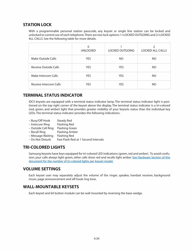
STATION LOCKWith a programmable personal station passcode, any keyset or single line station can be locked andunlocked to control use of each telephone.There are two lock options: 1=LOCKED OUTGOING and 2=LOCKEDALL CALLS. See the following table for more details.
TERMINAL STATUS INDICATORiDCS keysets are equipped with a terminal status indicator lamp. The terminal status indicator light is posi-tioned on the top right corner of the keyset above the display. The terminal status indicator is a tri-colored(red, green, and amber) light that provides greater visibility of your keysets status than the individual keyLEDs. The terminal status indicator provides the following indications:
– Busy/Off Hook Steady Red– Intercom Ring Flashing Red– Outside Call Ring Flashing Green– Recall Ring Flashing Amber– Message Waiting Flashing Red– Do Not Disturb Fast Flash Red at 1 Second Intervals
TRI-COLORED LIGHTSSamsung keysets have keys equipped for tri-colored LED indications (green, red and amber). To avoid confu-sion, your calls always light green, other calls show red and recalls light amber. See Hardware Section of thisdocument for the number of tri-colored lights per keyset model.
VOLUME SETTINGSEach keyset user may separately adjust the volume of the ringer, speaker, handset receiver, backgroundmusic, page announcement and off-hook ring tone.
WALL-MOUNTABLE KEYSETSEach keyset and 64 button module can be wall mounted by reversing the base wedge.
4.34
0UNLOCKED
1LOCKED OUTGOING
2LOCKED ALL CALLS
Make Outside Calls YES NO NO
Receive Outside Calls YES YES NO
Make Intercom Calls YES YES NO
Receive Intercom Calls YES YES NO
4.35
Account Code Display
Call Duration Timer
Call for Group Identification
Call Logs
Call Processing Information
Caller ID Information
Calling Party Name
Calling Party Number
Conference Information
Date and Time Display
Dial by Name
Dialed Number
Enhanced Station Programming
Identification of Recalls
Identification of Transfers
Message Waiting Caller Number
Outside Line Identification
Override Identification
Programmed Message Display
Soft Keys
Stopwatch Timer
Text Messaging
UCD Supervisor Displays
DISPLAY FEATURES
4.3 DISPLAY FEATURES DESCRIPTIONS
ACCOUNT CODE DISPLAYAccount codes are conveniently displayed for easy confirmation. If entered incorrectly, users may press theACCOUNT key again and reenter the account code.
CALL DURATION TIMERThe system can automatically time outside calls and show the duration in minutes and seconds. Station usersmay manually time calls by pressing the TIMER button.
CALL FOR GROUP IDENTIFICATIONWhen a call is made to a station group, the display shows [CALL FOR GROUP] and the user’s group number.These calls can be answered with a different greeting than calls to the user’s extension number.
CALL LOGSDisplay keyset users may view telephone numbers in incoming and outgoing call logs. With the press of abutton the entry can be cleared, dialed or the CID Name, Number and Date of a specific call can be reviewed.
CALL PROCESSING INFORMATIONDuring everyday call handling, the keyset display will provide information that is helpful and in some casesinvaluable. Displays such as [CALL FROM 203], [TRANSFER TO 202], [701: RINGING], [TRANSFER FM 203], [708busy], [Camp on to 204], [Recall from 204], [Call for 501], [message from 204] and [FWD ALL to 204] keep usersinformed of what is happening and where they are. In some conditions, the user is prompted to take actionand in other cases the user receives directory information.
CALLER ID INFORMATIONCaller ID information is dependent on the use of display keysets. The following list explains the displays thatare used with Caller ID.
Name / Number Display
During normal incoming CO calls, Caller ID name and number can be display simultaneously in the display ofeach keyset. When receiving a transferred CO call, each display keyset user can decide if he/she wants to seethe Caller ID name or Caller ID number in the display. Regardless of which one is selected to be seen first, theNND key is pressed to view the other piece of CID information.
Next Call
In the event that there is a call waiting or a camped-on call at the user’s keyset, the user can press the NEXTkey to display the Caller ID information associated with the next call in queue at the station. Either the CIDname or CID number will show in the display depending on the N/N (MMC 119) selection.
Save CID/ANI Number
At any time during an incoming call that provides CID information, the user may press the SAVE key.This savesthe CID number in the Save Number feature. Pressing the SAVE number redial key will dial the CID number.The system must be using LCR to dial the saved number.
Store CID/ANI Number
At any time during an incoming call that provides CID information, the user may press the STORE key. Thissaves the CID number as a speed dial number in the personal speed dial list. The system must be using LCRto dial the stored number.
Inquire Park/Hold
When a user is informed that an incoming call is on hold or has been parked, the user may view the Caller IDor ANI information before he/she retrieves the call.This will influence how the user chooses to handle the call.
CID/ANI Review List
This feature allows display keyset users to review CID information for calls sent to their stations. This list canbe from ten to fifty calls in a first in, first out basis.The list includes calls that were answered and calls that rangthe user’s station but that were not answered. When reviewing this list, the user can press one button to dialthe person back. The system must be using LCR to dial the stored number.
Investigate
This feature allows selected stations with a special class of service to investigate any call in progress. IfCID/ANI information is available for an incoming call, the selected stations can know to whom the OfficeServ7100 user is speaking. On outgoing calls, the selected stations can see who was called. After investigating, theselected stations may barge-in on the conversation, disconnect the call or hang up.
Abandon Call List
The system has a system-wide abandon call list that stores CID/ANI information for calls that rang but werenot answered. The list is accessed using the operator’s passcode. When reviewing this list, you are providedoptions to CLEAR the entry or DIAL the number. You can use the NND key to toggle between the CID name,CID or ANI number and the date and time the call came in. The system must be using LCR to dial numbersfrom the abandon call list. The abandoned call list will store up to 100 unanswered calls.
CALLING PARTY NAMEFor intercom calls, display keysets show the calling party’s name before answering.The names must be storedin the system directory list and can be up to 11 characters long.
4.36
CALLING PARTY NUMBERWhen an intercom call is received, all display stations show the calling party’s extension number before thecall is answered.
CONFERENCE INFORMATIONWhen a conference is set up, each extension and outside line number is displayed at the controlling stationwhen it is added. When a station is added, its display shows [Conf with xxx] alerting the user that other par-ties are on the line.
DATE AND TIME DISPLAYIn the idle condition, the current date and time are conveniently displayed. Display keysets can have a 12 or24 hour clock in either the ORIENTAL or WESTERN display format with information shown in upper case orlower case letters.
DIAL BY NAMEEach station and speed dial number can have an associated directory name. Any station or speed dial num-ber can be selected by scrolling alphabetically through a directory list. There are three directories:
1. System wide speed dial list2. Personal speed dial list3. Station directory list
This online “phone book” allows display keyset users to look up and dial any speed dial number or station inseconds.
DIALED NUMBERWhen an outside call is made, digits are displayed as the user dials them. If the display indicates an incorrectnumber was dialed, the user can quickly hang up before billing begins.
ENHANCED STATION PROGRAMMINGPersonal programming options are easier to select and confirm with the help of the display.
IDENTIFICATION OF RECALLSHold recalls and transfer recalls are identified differently than other ringing calls. Hold recalls indicate therecalling line or station number and the associated name.Transfer recalls indicate the recalling line or stationand where it is coming from.
IDENTIFICATION OF TRANSFERSThe display will identify who transferred a call to the user.
MESSAGE WAITING CALLER NUMBERWhen the message indication is on, pressing the MESSAGE button displays the station number(s) of the per-son(s) who have messages for the user. Display keyset users can scroll up and down to view message indica-tions.
4.37

OUTSIDE LINE IDENTIFICATIONEach line can be identified with an 11 character name. Incoming calls display this name before the call isanswered. This feature is helpful when individual lines must be answered with different greetings.
OVERRIDE IDENTIFICATIONIf another station barges-in on a user’s conversation, the display will alert the user with a [Barge from 2xx] dis-play if the system is set for barge-in with tone.
PROGRAMMED MESSAGE DISPLAYPreprogrammed station messages set by other stations are displayed at the calling station’s keyset.
SOFT KEYSBelow the display, there are three soft keys and a SCROLL button.These keys allow the user to access featuresin his/her class of service without requiring the keyset to have designated feature keys.
STOPWATCH TIMERDisplay keyset users find this feature very convenient to time meetings, calls and other functions. Users sim-ply press once to start the timer and press again to stop the timer.
TEXT MESSAGINGThis feature allows two display keyset users to respond to each other with preprogrammed messages. Afterreceiving an Off Hook Voice Announcement or Station Camp-On, you may respond with a text message whilecontinuing to talk and listen to your outside party. The other station can view this message and take theappropriate action or respond back with another text message.
Up to 24 display station users can program their own individual ten (10) text messages that can be sent toanother display keyset. Only the display keysets that are allowed in the system programming (MMC 611) willreceive the (TMSG) text message softkey in the display and can use this feature.
UCD SUPERVISOR DISPLAYSWhen a UCD supervisor key is pressed, supervisors can view information about the UCD group, calls oragents.
Call Screen
This allows the supervisor to view how many calls are in queue, the longest wait time, how many calls havebeen received today, what the average time in queue is and how many calls were abandoned.
Agent Screen
This allows the supervisor to monitor how many agents are logged in, check each agents status (IN GROUP,OUT OF GROUP, or DND), view each agents total number of calls, average call length or average ring time.
Note: Accessing this screen will also allow a Supervisor to change the status of each agent (IN GROUP, OUTOF GROUP, or DND).
4.38
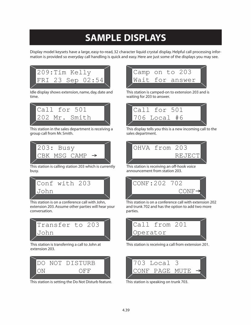
Idle display shows extension, name, day, date andtime.
This station is camped-on to extension 203 and iswaiting for 203 to answer.
This station in the sales department is receiving agroup call from Mr. Smith.
This display tells you this is a new incoming call to thesales department.
This station is calling station 203 which is currentlybusy.
This station is receiving an off-hook voiceannouncement from station 203.
This station is on a conference call with John,extension 203. Assume other parties will hear yourconversation.
This station is on a conference call with extension 202and trunk 702 and has the option to add two moreparties.
This station is transferring a call to John atextension 203.
This station is receiving a call from extension 201.
This station is setting the Do Not Disturb feature. This station is speaking on trunk 703.
209:Tim Kelly
FRI 23 Sep 02:54
Call for 501
202 Mr. Smith
203: Busy
CBK MSG CAMP �
Conf with 203
John
Transfer to 203
John
DO NOT DISTURB
ON OFF
Camp on to 203
Wait for answer
Call for 501
706 Local #6
OHVA from 203
REJECT
CONF:202 702
CONF�
Call from 201
Operator
703 Local 3
CONF PAGE MUTE �
SAMPLE DISPLAYSDisplay model keysets have a large, easy-to-read, 32 character liquid crystal display. Helpful call processing infor-mation is provided so everyday call handling is quick and easy. Here are just some of the displays you may see.
4.39

SAMSUNG TELECOM
CALL FOR:500
This display shows an incoming call fromSamsung Telecom ringing at group 500.
13054264100
702:RINGING
This display shows an incoming call from 1-305-426-4100 on Line 702 ringing directly at yourstation.
SAMSUNG TELECOM
CLEAR NND DIAL�
This display shows an entry in a station reviewlist showing the three initial options.The arrowindicates other options available to you bypressing the SCROLL key.
SAMSUNG TELECOM
BARGE NND DROP
This display shows an investigation of a stationthat is talking to Samsung Telecom. Investigatorcan BARGE-in to the conversation, DROP the callfrom the system or examine further NNDinformation.
This display shows the information on theabandoned call list.This call came in on May 25at 9:41 on line 702.The user can CLEAR theentry, DIAL the caller back or examine furtherNND information.
A.M.
TALKING TO:203
BARGE DROP
13054264100
TRANSFER FM 201
This display shows a call from 1-305-426-4100that has been transferred to you from station201.
05/25,09:41,702
CLEAR NND DIAL
SAMSUNG TELECOM
ANS NND IGNORE
This display is seen while using the INQUIREfeature. It shows the three options availablewhile you are checking on a held or parked call.
13054264100
NEXT NND ANS
This display is seen while examining calls inqueue at your keyset.
This display can be seen when investigating anintercom call.The investigator can BARGE-in orDROP the connection.
SAMPLE CALLER ID
4.40
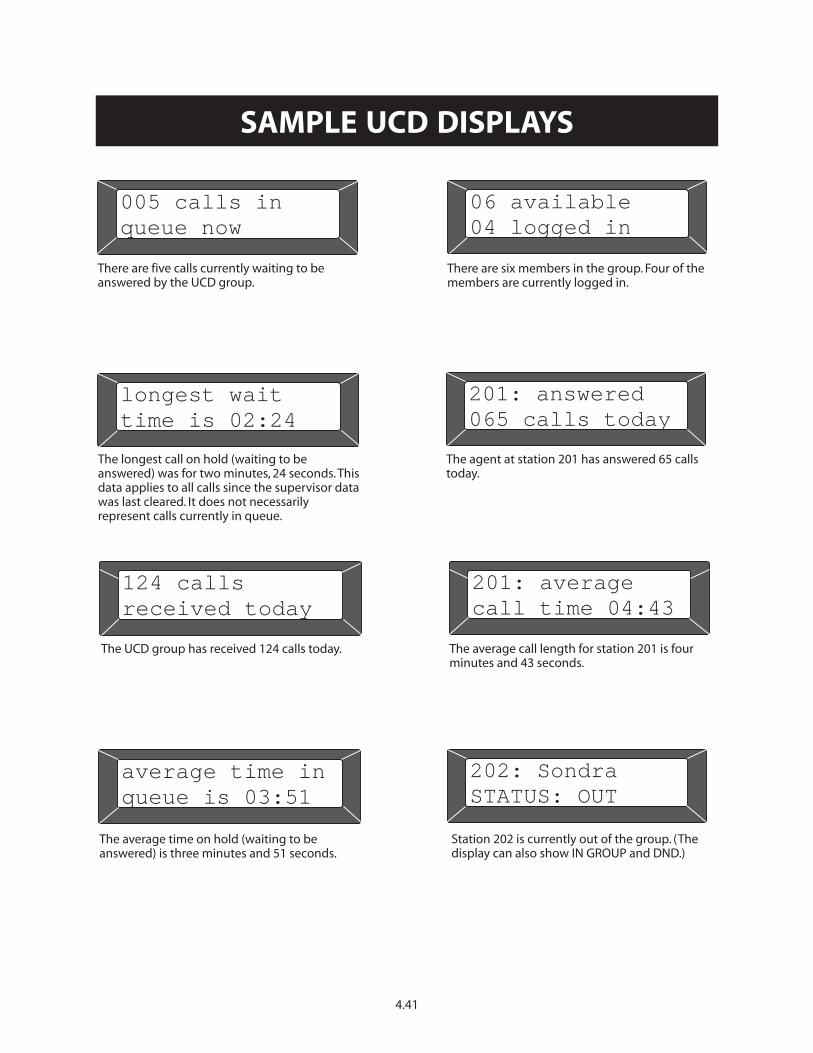
average time in
queue is 03:51
The average time on hold (waiting to beanswered) is three minutes and 51 seconds.
005 calls in
queue now
There are five calls currently waiting to beanswered by the UCD group.
201: answered
065 calls today
The agent at station 201 has answered 65 callstoday.
124 calls
received today
The UCD group has received 124 calls today.
There are six members in the group. Four of themembers are currently logged in.
202: Sondra
STATUS: OUT
longest wait
time is 02:24
The longest call on hold (waiting to beanswered) was for two minutes, 24 seconds.Thisdata applies to all calls since the supervisor datawas last cleared. It does not necessarilyrepresent calls currently in queue.
06 available
04 logged in
201: average
call time 04:43
The average call length for station 201 is fourminutes and 43 seconds.
Station 202 is currently out of the group. (Thedisplay can also show IN GROUP and DND.)
SAMPLE UCD DISPLAYS
4.41
AUTO ATTENDANT FEATURESApplication Backup and Restore
Automatic Self Configuration
Caller ID Routing
Camp-On Support
Fax Detection and Routing
Global Operator Access
Interruptible Voice Prompts
Menu Tree Routing
Music-On-Hold Support
Multiple Language Support
Password Security
Question & Answer Forms
Recordable System Prompts
Schedule-Oriented Call Processing
Special Events Scheduler
System Activity Reports
Transfer Direct to Mailbox
Voice Prompted Programming
Web Programming
4.4 AUTOMATED ATTENDANT FEATURES DESCRIPTIONS
APPLICATION BACKUP AND RESTOREThe customer’s automated attendant application data can be backed up for archiving and restoration pur-poses.
AUTOMATIC SELF CONFIGURATIONDuring the initial setup of the phone system the automated attendant will automatically set up greetings andmenus used in a typical install. This greatly reduces system setup time. By default the system will create dayand night menus that allow users to dial any extension or press 0 for the operator.
CALLER ID ROUTINGIf the customer’s Central Office provides Caller ID this information can be used by the automated attendantto identify and route calls.
CAMP-ON SUPPORTThe automated attendant can be configured so that calls transferred to a busy station can be “camped on” tothe station, causing it to ring with a special off-hook ring tone even while in a call.
FAX DETECTION AND ROUTINGThe OfficeServ 7100 automated attendant can detect a fax call and transfer it to any extension in the system.This detection can be enabled in any menu and assigned to different destinations for each menu.
GLOBAL OPERATOR ACCESSCallers connected to the automated attendant can press 0 at any time to be transferred to the operatorgroup. This feature requires that a valid operator group be defined in MMC 600.
INTERRUPTIBLE VOICE PROMPTSUsers may dial a menu option at any time during a prompt or greeting, without the need to wait for thatoption to be spoken aloud. This is very useful for users who are familiar with the options and wish to speedup the process.
4.42
MENU TREE ROUTINGThe automated attendant routes calls through a menu tree structure. Menus are able to process callers by avariety of means, such as: digits entered, caller ID, or DNIS information. Callers may be transferred to a multi-tude of destinations such as stations, groups, the voicemail directory, or 'Question and Answer' applications.Menus can be cascaded together to form complex application trees.
MUSIC-ON-HOLD SUPPORTMusic or announcements may be recorded into the automated attendant and used in the phone system asMusic-On-Hold.The recorded announcement or music will play in a continuous loop and may be used to pro-vide custom on-hold announcements or promotional messages.
MULTIPLE LANGUAGE SUPPORTThe OfficeServ 7100 automated attendant supports up to 2 simultaneous languages.The default language isEnglish (United States). Spanish (Castilian) and French (Canadian) are also installed by the factory as standardlanguages. A list of available languages can be obtained through your local authorized Samsung serviceprovider.
PASSWORD SECURITYAutomated attendant administration is password protected to prevent unauthorized access.
QUESTION & ANSWER FORMSThis feature allows the OfficeServ 7100 to be used to conduct surveys or collect responses to a questionnaire.Answers can be collated and stored in a specific mailbox or split into many different mailboxes. This is a use-ful tool any time you need to collect specific information from a caller but do not want to devote a staff mem-ber to take the calls directly. Answer messages can be prefixed with an optional header message, which helpsin transcription by preventing silence in the event the caller skips a question. There is no fixed limit to thenumber of questions in a Q&A application, nor is there a fixed limit to the number of possible Q&A applica-tions.
RECORDABLE SYSTEM PROMPTSThe OfficeServ 7100 automated attendant includes an integrated voice studio that allows you to edit or re-record any prompt in the system. You can also create new prompts in order to help unify your companyimage.
SCHEDULE-ORIENTED CALL PROCESSINGThe OfficeServ 7100 automated attendant processes calls according to an administrator controlled schedul-ing table.This table determines which mode of operation the system will run in (day, night, holiday, etc). Eachprogramming object in the automated attendant can be configured to route calls differently depending onthe active operating mode.The schedule table can set mode by individual port, time of day, day of the week,and calendar date. Up to 99 modes can be created, and the system administrator can manually override theschedule at any time from a touchtone telephone.
SPECIAL EVENTS SCHEDULERWhen your business closes because of a holiday or a special event the OfficeServ 7100 can provide appropri-ate prompting to your callers by using the scheduling feature. Events can be pre-programmed to activateautomatically or activated on the fly by an administrator.
4.43
SYSTEM ACTIVITY REPORTSThe OfficeServ 7100 provides many useful automated attendant reports. These reports can be used to man-age traffic patterns as well as to detect misuse of the system. Administrators can view these reports from theweb programming interface.
TRANSFER DIRECT TO MAILBOXThe OfficeServ 7100 automated attendant can transfer callers directly to a voicemail box without the need toring a station first. This is handy for things such as night time message taking or for playing announcements,such as directions, to a customer.
VOICE PROMPT PROGRAMMINGThe OfficeServ 7100 provides a robust telephone user interface (TUI) for automated attendant programming.This TUI allows administrators the ability to record prompts and change operating modes.
WEB PROGRAMMINGConfiguration of the OfficeServ 7100 automated attendant is performed through a web-based applicationcalled OfficeServ VAR which runs on an embedded web server inside the system’s main processor.This allowsthe automated attendant to be programmed from any PC on the LAN that has Internet Explorer installed.With proper router configuration the web server can be accessed remotely from anywhere on the internet.
4.44
Availability Schedule
Administration Mailbox
Answering Machine Emulation
Automatically Forward Messages
Automatically Log In
Automatic Self Configuration
Busy Station Queuing
Callbacks
Call Blocking
Date / Time Stamp
Direct Messaging / Quick Memos
Find Me
Flexible Numbering Plan
Follow Me
Grouping / Sorting of Messages
Group Mailboxes
Individually Defined Mailboxes and Stations
Keyset Display and Soft Key Support
Mailbox Backup and Restore
Message Delivery Options
Message Length Controls
Message Notification
Message Playback Options
Message Undelete
Message Unsend
Message Waiting Indication
Minimum Password Length
Multiple Alphabetical Directories
Multiple Personal Greetings
Name Addressing
Network Mailboxes (AMIS)
Night Intercept
Park and Overhead Page
Personal Mailbox Administration
Personal Single Digit Options
Programmable Message Retention
Retrieve Public Caller
Schedule Future Delivery
Subscriber Administration
Voice Prompted Programming
4.5 VOICE MAIL FEATURES DESCRIPTIONS
AVAILABILITY SCHEDULEOfficeServ 7100 voicemail subscribers can configure a weekly availability schedule that lets the system knowwhen they will be available to take calls. Calls made outside of normal working hours will be sent directly tothe user’s voicemail box.
ADMINISTRATION MAILBOXSubscribers can be designated as Mailbox Administrators, giving them the added functionality of being ableto record and send broadcast messages.
ANSWERING MACHINE EMULATIONThis feature allows you to hear calls being left in your voicemail box through the speaker of your keyset, sim-ilar to a home answer machine.
AUTOMATICALLY FORWARD MESSAGESVoicemail boxes in the OfficeServ 7100 can be configured to automatically forward messages to anothermailbox optionally leaving a copy in the original mailbox.
4.45
VOICE MAIL FEATURES
AUTOMATICALLY LOG INA user’s voicemail can be configured such that upon calling in to the voicemail they are automatically loggedin to their mailbox without being prompted for a password.
AUTOMATIC SELF CONFIGURATIONDuring the initial setup of the phone system the OfficeServ 7100 will automatically create mailboxes for eachstation in the system, greatly reducing system setup time.
BUSY STATION QUEUINGAn administrator may configure a voicemail box to allow queuing when the subscriber’s phone is busy.Callers are given an option to hold for the busy station and can be informed of their position in queue andthe estimated hold time.
Note: Each queued caller will consume a voicemail port.
CALLBACKSWhen listening to voice mail messages subscribers are given the option to automatically call back the personwho left the message.This call back feature may be allowed for internal calls and / or external calls. For exter-nal calls the number called back is determined by Caller ID, which requires that Caller ID be received from thephone company. Long distance callback numbers can be blocked if desired.
CALL BLOCKINGThe administrator may grant voicemail subscribers the option to enable call blocking. When activated, callblocking prevents the voicemail and automated attendant from trying to call the subscriber’s keyset, insteadforwarding them straight to the subscriber’s voicemail box.
DATE / TIME STAMPAll voicemail messages are stamped with the date and time they were received.This information is spoken tothe subscriber before the message by default, but can be set to only be spoken upon request.
DIRECT MESSAGING / QUICK MEMOSThe OfficeServ 7100 allows voicemail subscribers to quickly leave voice messages for other subscribers, with-out the need to actually call the subscriber.
FIND MEIf authorized to do so, a subscriber can create a list of stored telephone numbers for their mailbox. Whencallers reach the subscribers voicemail they are given the option to try to locate the subscriber.The OfficeServ7100 will dial through the stored telephone number list attempting to reach the subscriber. If the subscriberis not reached or chooses to reject the call, the caller will be sent to the subscriber’s voicemail box.
FLEXIBLE NUMBERING PLANThe OfficeServ 7100 voicemail is capable of distinguishing between similar dialing strings. For example mail-boxes 2, 201, and 2011 can all coexist without risk of callers being misdirected.This is very useful in situationswhere one subscriber may require multiple voicemail boxes.The voicemail can accommodate mailboxes withas few as 1 or as many as 10 digits.
4.46

FOLLOW MEIf authorized to do so, a subscriber can choose to have callers that reach their voicemail box to be forwardedto another destination, such as a cell phone. The OfficeServ 7100 will dial the new destination and promptthe subscriber to accept or reject the call. If the subscriber is not reached or chooses to reject the call, thecaller will be sent to the subscriber’s voicemail box.
GROUPING / SORTING OF MESSAGESIf authorized to do so, a subscriber can choose to have callers that reach their voicemail box to be forwardedto another destination, such as a cell phone. The OfficeServ 7100 will dial the new destination and promptthe subscriber to accept or reject the call. If the subscriber is not reached or chooses to reject the call, thecaller will be sent to the subscriber’s voicemail box.
GROUP MAILBOXESThe OfficeServ 7100 provides the ability to create voicemail boxes that are associated to a station grouprather than a single station.
INDIVIDUALLY DEFINED MAILBOXES AND STATIONSThe OfficeServ 7100 allows creation of voicemail boxes that do not have associated stations. This is ideal forcreating announcement mailboxes or for allowing remote users to have voicemail without actually being apart of the phone system.
KEYSET DISPLAY AND SOFT KEY SUPPORTFor subscribers who have a station equipped with a display the OfficeServ 7100 voicemail application canprovide additional functionality. The display will be used to display notification of new messages. Also, whennavigating the voicemail options the display will enable special soft key commands for faster navigationthrough the system.
MAILBOX BACKUP AND RESTOREThe customer can backup mailbox data for archiving and restoration purposes.
MESSAGE DELIVERY OPTIONSWhen creating a quick memo or messaging another subscriber a subscriber may set any of a number of pri-ority delivery options. Messages can be flagged any of the following: Urgent Priority, Return Receipt Request,Callback Request, Private, or Reply Required.
MESSAGE LENGTH CONTROLSThe administrator can configure many options to control the usage of disk space in the OfficeServ 7100voicemail. These options include setting the maximum number of messages a mailbox can take, the maxi-mum greeting length a subscriber can record, and the maximum length of messages left by a caller. Theadministrator can even configure an entire mailbox to be automatically deleted after a certain period of time.These options help to more efficiently manage message storage space and prevent abuse of the system.
MESSAGE NOTIFICATIONThe OfficeServ 7100 voicemail can alert subscribers of messages in a variety of ways. In addition to the nor-mal keyset indicator, the subscriber can be notified via: cell phone, pager, and e-mail. Any or all of theseoptions can be enabled.This allows subscribers a great deal of flexibility in how and where they receive theirmessages.
4.47
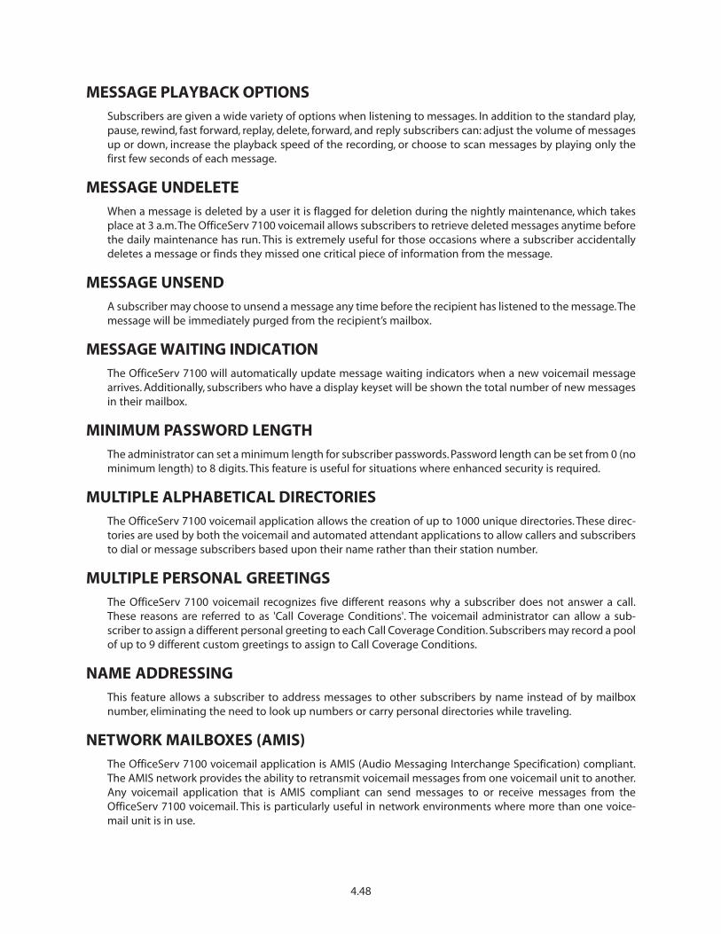
MESSAGE PLAYBACK OPTIONSSubscribers are given a wide variety of options when listening to messages. In addition to the standard play,pause, rewind, fast forward, replay, delete, forward, and reply subscribers can: adjust the volume of messagesup or down, increase the playback speed of the recording, or choose to scan messages by playing only thefirst few seconds of each message.
MESSAGE UNDELETEWhen a message is deleted by a user it is flagged for deletion during the nightly maintenance, which takesplace at 3 a.m.The OfficeServ 7100 voicemail allows subscribers to retrieve deleted messages anytime beforethe daily maintenance has run. This is extremely useful for those occasions where a subscriber accidentallydeletes a message or finds they missed one critical piece of information from the message.
MESSAGE UNSENDA subscriber may choose to unsend a message any time before the recipient has listened to the message.Themessage will be immediately purged from the recipient’s mailbox.
MESSAGE WAITING INDICATIONThe OfficeServ 7100 will automatically update message waiting indicators when a new voicemail messagearrives. Additionally, subscribers who have a display keyset will be shown the total number of new messagesin their mailbox.
MINIMUM PASSWORD LENGTHThe administrator can set a minimum length for subscriber passwords. Password length can be set from 0 (nominimum length) to 8 digits. This feature is useful for situations where enhanced security is required.
MULTIPLE ALPHABETICAL DIRECTORIESThe OfficeServ 7100 voicemail application allows the creation of up to 1000 unique directories. These direc-tories are used by both the voicemail and automated attendant applications to allow callers and subscribersto dial or message subscribers based upon their name rather than their station number.
MULTIPLE PERSONAL GREETINGSThe OfficeServ 7100 voicemail recognizes five different reasons why a subscriber does not answer a call.These reasons are referred to as 'Call Coverage Conditions'. The voicemail administrator can allow a sub-scriber to assign a different personal greeting to each Call Coverage Condition. Subscribers may record a poolof up to 9 different custom greetings to assign to Call Coverage Conditions.
NAME ADDRESSINGThis feature allows a subscriber to address messages to other subscribers by name instead of by mailboxnumber, eliminating the need to look up numbers or carry personal directories while traveling.
NETWORK MAILBOXES (AMIS)The OfficeServ 7100 voicemail application is AMIS (Audio Messaging Interchange Specification) compliant.The AMIS network provides the ability to retransmit voicemail messages from one voicemail unit to another.Any voicemail application that is AMIS compliant can send messages to or receive messages from theOfficeServ 7100 voicemail. This is particularly useful in network environments where more than one voice-mail unit is in use.
4.48

NIGHT INTERCEPTIf a subscriber configures their availability schedule the system will automatically intercept calls made afterhours. Instead of attempting to ring the subscriber at their station, the caller is immediately shunted to thevoicemail box to leave a message.
NOTE: For this feature to work properly calls must be routed to the subscriber through the automated atten-dant.
PARK AND OVERHEAD PAGEFor those subscribers who are frequently away from their desk, the OfficeServ 7100 voicemail provides a Parkand Page capability.When a caller reaches one of these subscribers they can be given the option to page thesubscriber. The subscriber is then paged and given the option to pick up the caller. If the subscriber rejectsthe call or does not respond the caller is routed to the subscriber’s voicemail box.
PERSONAL MAILBOX ADMINISTRATIONThe OfficeServ 7100 voicemail application provides an extensive telephone user interface for subscribers touse for configuration of their mailbox. From this interface users can configure every aspect of their mailboxsuch as: changing passwords, recording and editing greetings, setting up stored telephone numbers, settingavailability schedules, and more.
PERSONAL SINGLE DIGIT OPTIONSThe OfficeServ 7100 voicemail provides the administrator the ability to configure single digit options for asubscriber’s mailbox. When callers reach the subscriber’s voicemail they are presented with the ability to usethese single digit options. This feature is useful for giving callers the ability to dial other departments oraccess automated attendant functions.
PROGRAMMABLE MESSAGE RETENTIONThe administrator may set a specific time limit to store messages for a subscriber’s voicemail box. When amessage has not been listened to for this length of time it will be automatically deleted. This option is con-figured on a per-mailbox basis.
RETRIEVE PUBLIC CALLERIf a caller is holding or leaving a message for a subscriber and that subscriber logs in to their mailbox, theywill be notified that a caller is currently waiting for them and asked if they wish to retrieve the caller.The sub-scriber can then choose to speak to the caller or send them to the voicemail box to leave a message.
SCHEDULE FUTURE DELIVERYThe OfficeServ 7100 voicemail application allows subscribers to set a future delivery date when attemptingto send a quick memo or messaging another subscriber. This is very useful for creating “to-do” lists, or forsending such things as meeting or holiday reminders.
SUBSCRIBER ADMINISTRATIONThe OfficeServ 7100 provides an administrator access to a telephone user interface for system administra-tion. The system administration interface allows the administrator to create, delete, or edit voicemail boxes.Edit mode allows access to things such as resetting passwords and entering directory names.
4.49

VOICE PROMPTED PROGRAMMINGThe OfficeServ 7100 provides a robust telephone user interface (TUI) for voicemail configuration. This TUIallows administrators the ability to manage subscriber mailboxes. It also provides subscribers the ability toconfigure almost every aspect of their mailbox without the need to memorize a complicated series of key-strokes.
4.50

4.51
SMDR
REPORT
FOR
[STA
Miami
]Mar/21/1999
13:49
===============================================================================
TEXT
AUTH
TRK
MM/DD
STT.TIME
DURATION
FG
DIALED
DIGIT
ACCOUNT
CODE
===============================================================================
13951
725
03/21
13:51:17
00:00:08
IA
13951
725
03/21
13:51:25
00:00:14
IT
1217
744
03/21
13:51:29
00:00:14
IA
1235
725
03/21
13:51:39
00:00:06
T
1219
726
03/21
13:51:25
$10.75
O3056401067
*1234567890#
1217
744
03/21
13:51:43
00:00:40
I
1278
725
03/21
13:53:40
00:00:07
O18007864782
13951
726
03/21
13:54:45
00:00:07
IA
1219
03/21
13:55:03
GROUP
OUT
13951
726
03/21
13:54:52
00:00:30
IT
1217
726
03/21
13:55:22
00:00:16
TT
1235
03/21
13:55:30
DND
ON
1218
726
03/21
13:55:38
00:00:33
TT
1235
03/21
13:57:50
DND
OFF
1279
6398
727
03/21
13:57:32
$13.25
O3056401066
1219
03/21
14:00:45
GROUP
IN
1219
726
03/21
13:56:11
00:05:38
T
1296
725
03/21
13:54:40
00:07:06
O3055922900217
1219
717
03/21
14:03:57
00:00:15
O19544530000
*1234567890#
Ca
llTy
pe
Fla
g D
efin
itio
ns
0O
utg
oin
g C
all
DE
DIS
A c
all w
ith
err
or
IIn
com
ing
Cal
lT
Tran
sfer
red
cal
l th
atD
ID
ISA
cal
l in
was
term
inat
edD
OD
ISA
cal
l ou
tIT
Inco
min
g t
ran
sfer
FOO
utg
oin
g re
cord
of
FIIn
com
ing
cal
l fo
rwar
ded
tofo
rwar
ded
cal
lan
ext
ern
al n
um
ber
IAIn
com
ing
Rin
gO
TO
utg
oin
g t
r an
sfer
- O
utg
oin
g c
all
Tim
e B
efo
re B
ein
gm
ade
and
tra
nsf
erre
dA
nsw
ered
TTC
alle
r rec
eive
d a
tra
nsf
erre
dca
ll an
d t
ran
sfer
red
it a
gai
n
Acc
ou
nt
Co
de
1–12
Dig
its
Tele
ph
on
e N
o.D
iale
d1–
18 D
igit
s
Cal
l Typ
e Fl
ag2
Ch
arac
ters
Cal
l Du
rati
on
Hrs
:Min
s:Se
cso
r Cal
l Co
st
Tim
e C
all M
ade
or R
ecei
ved
Hrs
:Min
s:Se
cs
Dat
e C
all M
ade
or R
ecei
ved
Mo
nth
:Day
Au
tho
riza
tio
n C
od
e4
Dig
its
Ten
ant
1 D
igit
C.O
.Lin
e N
o.2–
4 D
igit
sEx
ten
sio
n2–
4 D
igit
s
4.6
SA
MP
LE S
MD
R P
RIN
TOU
T(W
ITH
OU
T C
ALL
ER ID
)

4.52
Cal
ler I
D N
um
ber
1–15
Dig
its
Cal
ler I
D N
ame
1–15
Ch
arac
ters
SMDR
REPORT
FOR
[STA
Miami
]Mar/21/99
13:49
==================================================================================================================
TEXT
AUTH
TRK
MM/DD
STT.TIME
DURATION
FG
DIALED
DIGIT
ACCOUNT
CODE
CID/ANI
NUMBER
CID/ANI
NAME
==================================================================================================================
13951
725
03/21
13:51:17
00:00:08
IA
13951
725
03/21
13:51:25
00:00:14
IT
13055922900
SAMSUNG
TELECOM
1217
744
03/21
13:51:29
00:00:14
IA
1235
725
03/21
13:51:39
00:00:06
T13055922900
SAMSUNG
TELECOM
1219
726
03/21
13:51:25
$10.75
O3056401067
*1234567890#
1217
744
03/21
13:51:43
00:00:40
I13055559748
PIZZA
DELIVERY
1278
725
03/21
13:53:40
00:00:07
O18007864782
13951
726
03/21
13:54:45
00:00:07
IA
1219
03/21
13:55:03
GROUP
OUT
13951
726
03/21
13:54:52
00:00:30
IT
13055922900
SAMSUNG
TELECOM
1217
726
03/21
13:55:22
00:00:16
TT
13055922900
SAMSUNG
TELECOM
1235
03/21
13:55:30
DND
ON
1218
726
03/21
13:55:38
00:00:33
TT
13055556420
PIZZA
DELIVERY
1235
03/21
13:57:50
DND
OFF
1279
6398
701
03/21
13:57:32
$13.25
O3056401066
1219
03/21
14:00:45
GROUP
IN
1219
726
03/21
13:56:11
00:05:38
T13055922900
SAMSUNG
TELECOM
1296
725
03/21
13:54:40
00:07:06
O3055922900217
Ca
llTy
pe
Fla
g D
efin
itio
ns
0O
utg
oin
g C
all
DE
DIS
A c
all w
ith
er r
or
IIn
com
ing
Cal
lT
Tran
sfer
red
cal
l th
at w
asD
ID
ISA
cal
l in
term
inat
edD
OD
ISA
cal
l ou
tIT
Inco
min
g t
ran
sfer
FOO
utg
oin
g re
cord
of
FIIn
com
ing
cal
l fo
rwar
ded
tofo
rwar
ded
cal
lan
ext
ern
al n
um
ber
AA
ban
do
ned
cal
lO
TO
utg
oin
g t
ran
sfer
- O
utg
oin
g c
all
IAIn
com
ing
Rin
gm
ade
and
tra
nsf
erre
dTi
me
Bef
ore
Bei
ng
TTC
alle
r rec
eive
d a
tra
nsf
erre
dA
nsw
ered
call
and
tra
nsf
erre
d it
ag
ain
Acc
ou
nt
Co
de
1-12
Dig
its
Tele
ph
on
e N
o.D
iale
d1–
18 D
igit
s
Cal
l Typ
e Fl
ag2
Ch
arac
ters
Cal
l Du
rati
on
Hrs
:Min
s:Se
cso
rC
all C
ost
Tim
e C
all M
ade
or R
ecei
ved
Hrs
:Min
s:Se
cs
Dat
e C
all M
ade
or R
ecei
ved
Mo
nth
:Day
Au
tho
riza
tio
nC
od
e4
Dig
its
Ten
ant
1 D
igit
C.O
.Lin
e N
o.2–
4 D
igit
sEx
ten
sio
n2–
4 D
igit
s
4.7
SA
MP
LE S
MD
R P
RIN
TOU
T(W
ITH
CA
LLER
ID/A
NI N
UM
BER
)

4.53
4.8 SAMPLE OF UCD EMBEDDED REPORT============================================================UCD GROUP 529 : SALES
FROM: SUN 02 Feb 00:00TO : SUN 02 Feb 02:54
CALL STATISTICS===============AVERAGE RING TIME(TIME TO ANSWER)......00:40NUMBER OF TIMES ALL AGENTS BUSY........00002AVERAGE TIME IN QUEUE..................00:51TOTAL CALLS RECEIVED...................00011LONGEST QUEUE TIME(TODAY)..............02:14TOTAL CALLS ABANDONED..................00004
AGENT STATISTICS================MEMBER AGENT NAME CALLS AVERAGE RING
ANSWERED CALL TIME TIME------------------------------------------------------------01 210 JOHN 0002 01:55 00:0502 211 SAM 0001 02:18 00:0603 208 MIKE 0003 01:22 00:0404 207 PETER 0001 03:16 00:05============================================================UCD GROUP 515 : SUPPORT
FROM: MON 03 Jan 08:30TO : SUN 02 Jan 02:54
CALL STATISTICS===============AVERAGE RING TIME(TIME TO ANSWER)......00:07NUMBER OF TIMES ALL AGENTS BUSY........00005AVERAGE TIME IN QUEUE..................01:06TOTAL CALLS RECEIVED...................00023LONGEST QUEUE TIME(TODAY)..............01:02TOTAL CALLS ABANDONED..................00001
AGENT STATISTICS================MEMBER AGENT NAME CALLS AVERAGE RING
ANSWERED CALL TIME TIME-----------------------------------------------------------01 223 FRED 0012 02:33 00:0802 213 JANE 0010 01:04 00:04
R ID
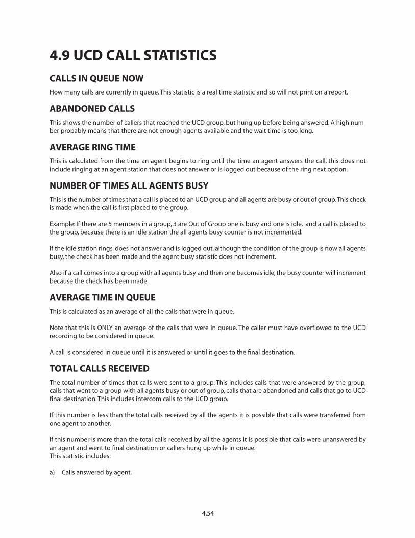
4.9 UCD CALL STATISTICS
CALLS IN QUEUE NOWHow many calls are currently in queue. This statistic is a real time statistic and so will not print on a report.
ABANDONED CALLSThis shows the number of callers that reached the UCD group, but hung up before being answered. A high num-ber probably means that there are not enough agents available and the wait time is too long.
AVERAGE RING TIMEThis is calculated from the time an agent begins to ring until the time an agent answers the call, this does notinclude ringing at an agent station that does not answer or is logged out because of the ring next option.
NUMBER OF TIMES ALL AGENTS BUSYThis is the number of times that a call is placed to an UCD group and all agents are busy or out of group.This checkis made when the call is first placed to the group.
Example: If there are 5 members in a group, 3 are Out of Group one is busy and one is idle, and a call is placed tothe group, because there is an idle station the all agents busy counter is not incremented.
If the idle station rings, does not answer and is logged out, although the condition of the group is now all agentsbusy, the check has been made and the agent busy statistic does not increment.
Also if a call comes into a group with all agents busy and then one becomes idle, the busy counter will incrementbecause the check has been made.
AVERAGE TIME IN QUEUEThis is calculated as an average of all the calls that were in queue.
Note that this is ONLY an average of the calls that were in queue. The caller must have overflowed to the UCDrecording to be considered in queue.
A call is considered in queue until it is answered or until it goes to the final destination.
TOTAL CALLS RECEIVEDThe total number of times that calls were sent to a group. This includes calls that were answered by the group,calls that went to a group with all agents busy or out of group, calls that are abandoned and calls that go to UCDfinal destination. This includes intercom calls to the UCD group.
If this number is less than the total calls received by all the agents it is possible that calls were transferred fromone agent to another.
If this number is more than the total calls received by all the agents it is possible that calls were unanswered byan agent and went to final destination or callers hung up while in queue.This statistic includes:
a) Calls answered by agent.
4.54

b) Calls that are not answered by an agent and go to final destination.
c) Calls that are sent to the UCD group but callers hang up before being answered.
LONGEST QUEUE TIME TODAYThis shows the longest call in queue today. The queue time is calculated as follows:
a) Queue time begins when a caller starts to hear the first UCD message.
b) Queue time ends when a caller is either
• Answered by an agent
• System gets disconnected from C.O. or
• Caller is transferred to final destination
LONGEST QUEUE TIME NOWThis shows the longest call currently in queue. The queue time is calculated as follows:
a) Queue time begins when a caller starts to hear the first UCD message.
b) Queue time ends when a caller is either
• Answered by an agent
• System gets disconnected from C.O. or
• Caller is transferred to final destination
4.55

4.10 UCD AGENT STATISTICS
LOGGED INThe number of stations programmed in the UCD group and the number of stations that are currently logged in.This statistic is a real time statistic and so will not print on a report.
STATUSThis screen shows the agents name, extension number and status. The status can be In Group, Out of group or inDND. This statistic is a real time statistic and so will not print on a report.
CALLS ANSWEREDThe total number of calls answered by the agent. This does not include ring no answer to an agent station. If thistotal number is less than the calls received by the group it is possible that calls were unanswered by an agent andwent to final destination or that callers hung up while in queue. If this total number is more than the calls receivedby the group it is possible that calls were transferred from one agent to another.
AVERAGE CALL TIMEThis is an average of all the call durations for the agent.
AVERAGE RING TIMEThis is an average of all the ring times for the agent. Ring times are previously explained.
4.56
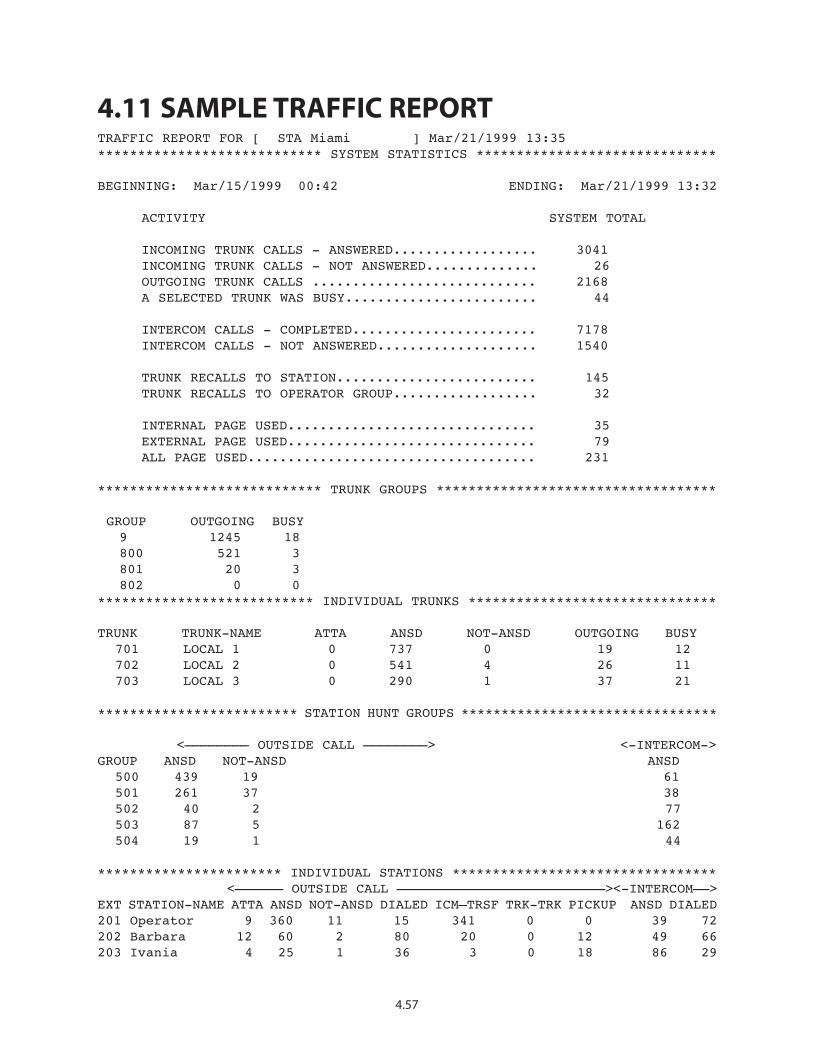
4.11 SAMPLE TRAFFIC REPORTTRAFFIC REPORT FOR [ STA Miami ] Mar/21/1999 13:35**************************** SYSTEM STATISTICS ******************************
BEGINNING: Mar/15/1999 00:42 ENDING: Mar/21/1999 13:32
ACTIVITY SYSTEM TOTAL
INCOMING TRUNK CALLS - ANSWERED.................. 3041INCOMING TRUNK CALLS - NOT ANSWERED.............. 26OUTGOING TRUNK CALLS ............................ 2168A SELECTED TRUNK WAS BUSY........................ 44
INTERCOM CALLS - COMPLETED....................... 7178INTERCOM CALLS - NOT ANSWERED.................... 1540
TRUNK RECALLS TO STATION......................... 145TRUNK RECALLS TO OPERATOR GROUP.................. 32
INTERNAL PAGE USED............................... 35EXTERNAL PAGE USED............................... 79ALL PAGE USED.................................... 231
**************************** TRUNK GROUPS ***********************************
GROUP OUTGOING BUSY 9 1245 18 800 521 3 801 20 3 802 0 0
*************************** INDIVIDUAL TRUNKS *******************************
TRUNK TRUNK-NAME ATTA ANSD NOT-ANSD OUTGOING BUSY 701 LOCAL 1 0 737 0 19 12702 LOCAL 2 0 541 4 26 11703 LOCAL 3 0 290 1 37 21
************************* STATION HUNT GROUPS ********************************
<———————— OUTSIDE CALL ————————> <-INTERCOM->GROUP ANSD NOT-ANSD ANSD
500 439 19 61 501 261 37 38 502 40 2 77503 87 5 162 504 19 1 44
*********************** INDIVIDUAL STATIONS ********************************* <—————— OUTSIDE CALL ——————————————————————————><-INTERCOM——>
EXT STATION-NAME ATTA ANSD NOT-ANSD DIALED ICM–TRSF TRK-TRK PICKUP ANSD DIALED201 Operator 9 360 11 15 341 0 0 39 72 202 Barbara 12 60 2 80 20 0 12 49 66203 Ivania 4 25 1 36 3 0 18 86 29
4.57

4.12 TRAFFIC REPORT OVERVIEW
A***************************** SYSTEM STATISTICS ****************************
1 BEGINNING: 04/01/99 08:00 ENDING: 04/01/99 17:30
2 ACTIVITY SYSTEM TOTAL
3 INCOMING TRUNK CALLS - ANSWERED..................00004 INCOMING TRUNK CALLS - NOT ANSWERED..............00005 OUTGOING TRUNK CALLS ............................00006 A SELECTED TRUNK WAS BUSY........................0000
7 INTERCOM CALLS - COMPLETED.......................00008 INTERCOM CALLS - NOT ANSWERED....................0000
9 TRUNK RECALLS TO STATION.........................000010 TRUNK RECALLS TO OPERATOR GROUP..................0000
11 INTERNAL PAGE USED...............................000012 EXTERNAL PAGE USED...............................000013 ALL PAGE USED....................................0000
1. BEGINNING & ENDINGThis identifies when the statistics were collected. It includes dates and time.
2. ACTIVITY: Overall summary of traffic in the system for activities 3 to 13.
3. INCOMING TRUNK CALLS-ANSWERED: These are any incoming trunk calls to the system. These calls arepegged when answered by any device and/or station in the system whether it is a new call or a recall.
4. INCOMING TRUNK CALLS-NOT ANSWERED: These are any incoming trunk calls that were not answered byany station or device in the systems. These are the same calls that would be flagged as abandoned in SMDR.
5. OUTGOING TRUNK CALLS: These are all outgoing trunk calls that were originated by any station or throughthe DISA feature. Outgoing trunk calls are valid calls as defined by the SMDR START TIME in MMC 501.
6. A SELECTED TRUNK WAS BUSY: Pegged every time a trunk or trunk group was busy regardless of the man-ner in which it was selected (e.g., DTS key, LCR,“9”, 7XX, TRK GROUP SELECT, SPD, External call forward, DISA).
7. INTERCOM CALLS COMPLETED: These are all intercom calls that were completed to any station, stationgroup or device.
8. INTERCOM CALLS NOT COMPLETED: These are all intercom calls that were not answered and resulted in thecalling party hanging up. A call to a station group that overflows to another station is considered notanswered whether the overflow destination did or did not answer.
9. TRUNK RECALLS TO STATION: These are trunk calls that were placed on any kind of hold and recalled a sta-tion.These are also trunk calls that were transferred and were not answered and recalled the transferring sta-tion. This includes members of the operator group that put calls on hold and then recall the operators sta-tion.
4.58
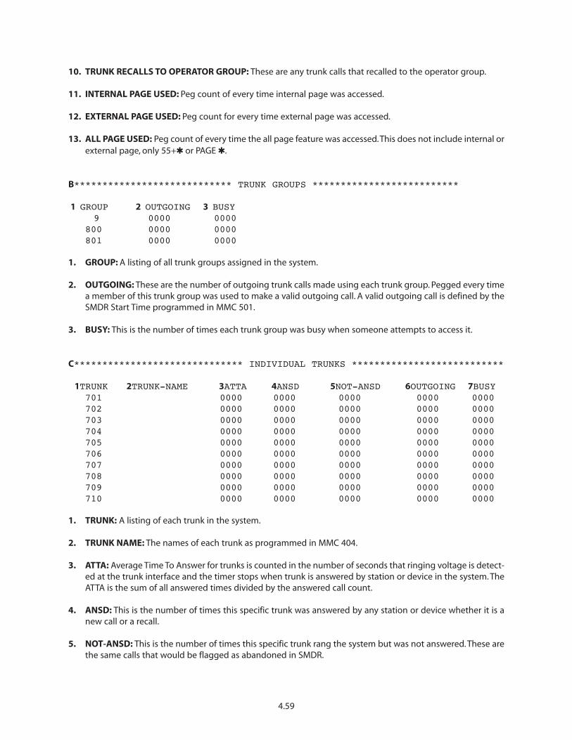
10. TRUNK RECALLS TO OPERATOR GROUP: These are any trunk calls that recalled to the operator group.
11. INTERNAL PAGE USED: Peg count of every time internal page was accessed.
12. EXTERNAL PAGE USED: Peg count for every time external page was accessed.
13. ALL PAGE USED: Peg count of every time the all page feature was accessed.This does not include internal orexternal page, only 55+� or PAGE �.
B**************************** TRUNK GROUPS **************************
1 GROUP 2 OUTGOING 3 BUSY9 0000 0000
800 0000 0000801 0000 0000
1. GROUP: A listing of all trunk groups assigned in the system.
2. OUTGOING: These are the number of outgoing trunk calls made using each trunk group. Pegged every timea member of this trunk group was used to make a valid outgoing call. A valid outgoing call is defined by theSMDR Start Time programmed in MMC 501.
3. BUSY: This is the number of times each trunk group was busy when someone attempts to access it.
C****************************** INDIVIDUAL TRUNKS ***************************
1TRUNK 2TRUNK-NAME 3ATTA 4ANSD 5NOT-ANSD 6OUTGOING 7BUSY701 0000 0000 0000 0000 0000702 0000 0000 0000 0000 0000703 0000 0000 0000 0000 0000704 0000 0000 0000 0000 0000705 0000 0000 0000 0000 0000706 0000 0000 0000 0000 0000707 0000 0000 0000 0000 0000708 0000 0000 0000 0000 0000709 0000 0000 0000 0000 0000710 0000 0000 0000 0000 0000
1. TRUNK: A listing of each trunk in the system.
2. TRUNK NAME: The names of each trunk as programmed in MMC 404.
3. ATTA: Average Time To Answer for trunks is counted in the number of seconds that ringing voltage is detect-ed at the trunk interface and the timer stops when trunk is answered by station or device in the system. TheATTA is the sum of all answered times divided by the answered call count.
4. ANSD: This is the number of times this specific trunk was answered by any station or device whether it is anew call or a recall.
5. NOT-ANSD: This is the number of times this specific trunk rang the system but was not answered. These arethe same calls that would be flagged as abandoned in SMDR.
4.59

6. OUTGOING: This is the number of times this trunk was used to make an outgoing call. A valid outgoing callis defined by the SMDR START TIME programmed in MMC 501.
7. BUSY: This is the number of times this trunk was busy when accessed by a button or dial code.
D**************************** STATION HUNT GROUPS **************************
<———————— 1 OUTSIDE CALL —————————————————————> 5 <-INTERCOM->2GROUP 3ANSD 4NOT-ANSD 6ANSD
500 0000 0000 0000501 0000 0000 0000502 0000 0000 0000503 0000 0000 0000504 0000 0000 0000
1. OUTSIDE CALLS: These statistics are for outside calls that reach these station groups regardless how theyarrive there.
2. GROUP: Listing of all station groups in the system.
3. ANSD: This column is a peg count of all answered trunk calls that rang to the specific group directory num-ber regardless of how these arrived.
4. NOT-ANSD: The number of times any trunk call directed to the specific group number was not answered byany member of the group.
5. INTERCOM: An intercom call made from a station or device within the system to the specific group number.
6. ANSD: This is a count of how many times an intercom call was answered by any group member of that spe-cific group.
E**************************** INDIVIDUAL STATIONS ***************************1 11
<—————————————————— OUTSIDE CALL —————————————————> <-INTERCOM->2 3 4 5 6 7 8 9 10 12 13
EXT STATION-NAME ATTA ANSD NOT-ANSD DIALED ICM-TRSF TRK–TRK PICKUP ANS DIALED201 0000 0000 0000 0000 0000 0000 0000 0000 0000202 0000 0000 0000 0000 0000 0000 0000 0000 0000203 0000 0000 0000 0000 0000 0000 0000 0000 0000204 0000 0000 0000 0000 0000 0000 0000 0000 0000205 0000 0000 0000 0000 0000 0000 0000 0000 0000
1. OUTSIDE CALLS: These statistics are for outside calls that in any way reach individual stations or devices.
2. EXT: Listing of all extension numbers in the system. This also includes AA/VM ports.
3. STATION NAME: The name for each particular station as programmed in MMC 104.
4. ATTA: Average Time To Answer for stations is counted in the number of seconds that ringing signal is appliedto a station for trunk calls and recalls.The ATTA is the sum of all answered times divided by the answered callcount. Use the same calculation method as used for individual trunk ATTA.
4.60
5. ANSD: This is a count of how many times an outside call was answered by the specific station. Outside callersrecalling a station are not counted again when they are answered.
6. NOT-ANSD: This is a count of how many times a trunk call was directed to the station but was not answeredby this station.
7. DIALED: Peg count of how many times the station made a valid outside call. An outside call is defined by theSMDR start time in MMC 501.
8. ICM-TRSF: This is the number of times a trunk call was successfully transferred to another station using theintercom. It includes both screened and unscreened transfer.
9. TRK–TRK: This is the number of times a trunk call was transferred to another trunk (tie line) This is called atrunk–to–trunk transfer. This field gets pegged every time the station completes a trunk to trunk transfer.
10. PICKUP: This is a count of the outside calls that were picked up by the specific station. Picked-up calls are callsthat are not ringing at your station but were answered by you. This peg count is separate from the numberof answered call in #5 of Individual Stations section E.
11. INTERCOM: Statistics for intercom calls. An intercom call made from a station or a station device within thesystem to another station.
12. ANSD: This is the number of times an intercom call was answered by this specific station. Screened transferscount as an answered intercom call.
13. DIALED: The number of times the specific station dialed another station or station group. Screened transferscount as a dialed intercom call.
4.61
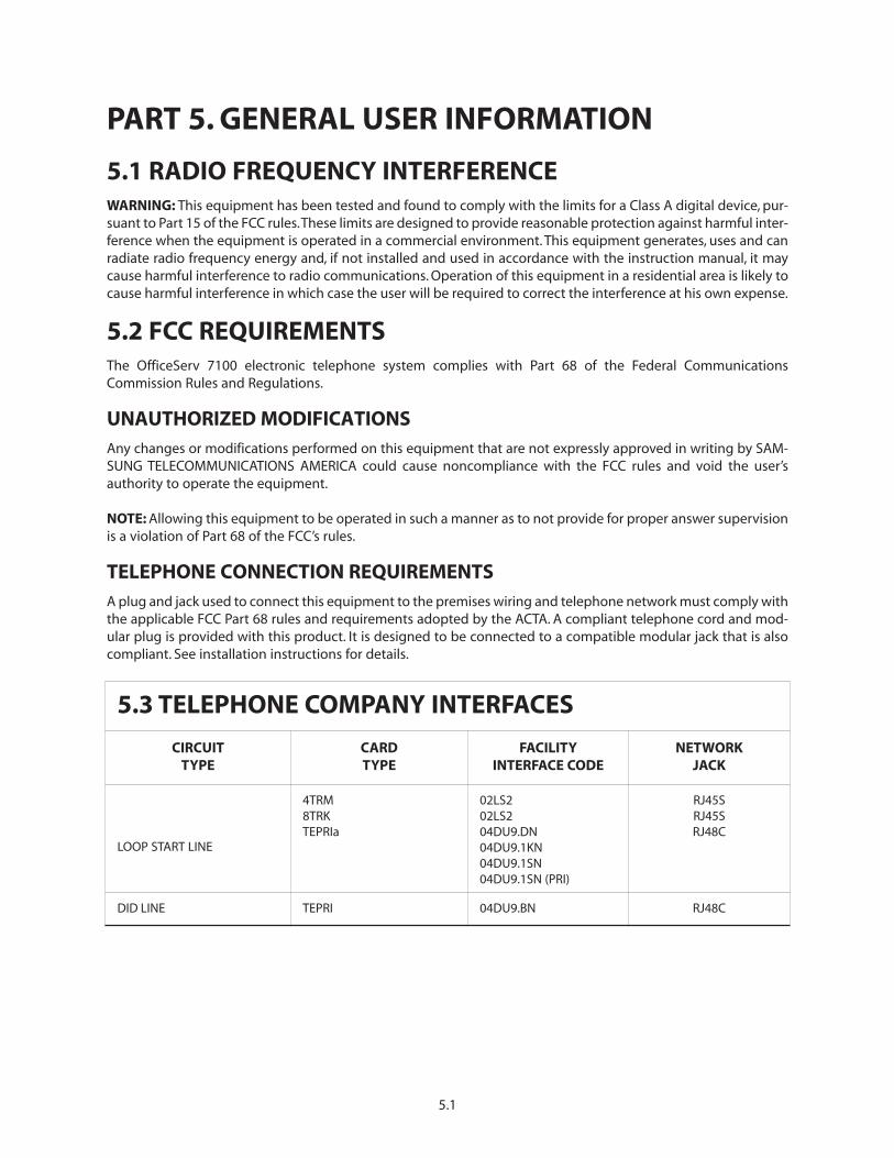
PART 5. GENERAL USER INFORMATION
5.1 RADIO FREQUENCY INTERFERENCEWARNING: This equipment has been tested and found to comply with the limits for a Class A digital device, pur-suant to Part 15 of the FCC rules.These limits are designed to provide reasonable protection against harmful inter-ference when the equipment is operated in a commercial environment. This equipment generates, uses and canradiate radio frequency energy and, if not installed and used in accordance with the instruction manual, it maycause harmful interference to radio communications. Operation of this equipment in a residential area is likely tocause harmful interference in which case the user will be required to correct the interference at his own expense.
5.2 FCC REQUIREMENTSThe OfficeServ 7100 electronic telephone system complies with Part 68 of the Federal CommunicationsCommission Rules and Regulations.
UNAUTHORIZED MODIFICATIONSAny changes or modifications performed on this equipment that are not expressly approved in writing by SAM-SUNG TELECOMMUNICATIONS AMERICA could cause noncompliance with the FCC rules and void the user’sauthority to operate the equipment.
NOTE: Allowing this equipment to be operated in such a manner as to not provide for proper answer supervisionis a violation of Part 68 of the FCC’s rules.
TELEPHONE CONNECTION REQUIREMENTSA plug and jack used to connect this equipment to the premises wiring and telephone network must comply withthe applicable FCC Part 68 rules and requirements adopted by the ACTA. A compliant telephone cord and mod-ular plug is provided with this product. It is designed to be connected to a compatible modular jack that is alsocompliant. See installation instructions for details.
5.1
5.3 TELEPHONE COMPANY INTERFACES
CIRCUIT TYPE
CARD TYPE
FACILITY INTERFACE CODE
NETWORK JACK
LOOP START LINE
4TRM8TRKTEPRIa
02LS202LS204DU9.DN04DU9.1KN04DU9.1SN04DU9.1SN (PRI)
RJ45SRJ45SRJ48C
DID LINE TEPRI 04DU9.BN RJ48C
RINGER EQUIVALENCE (REN)The REN of the 4TRM (1.38) is used to determine the number of devices that may be connected to a telephoneline. Excessive RENs on a telephone line may result in the devices not ringing in response to an incoming call. Inmost but not all areas, the sum of RENs should not exceed five (5.0). To be certain of the number of devices thatmay be connected to a line, as determined by the total RENs, contact the local telephone company. For earlierproducts, the REN is separately shown on the label.
INCIDENCE OF HARMIf this equipment, the OfficeServ 7100, causes harm to the telephone network, the telephone company will noti-fy you in advance that temporary discontinuance of service may be required. But if advance notice is not practi-cal, the telephone company will notify the customer as soon as possible. Also, you will be advised of your right tofile a complaint with the FCC if you believe it is necessary.
CHANGES TO TELEPHONE COMPANY EQUIPMENT OR FACILITIESThe telephone company may make changes in its facilities, equipment, operations or procedures that could affectthe operation of the equipment. If this happens, the telephone company will provide advance notice in order foryou to make necessary modifications to maintain uninterrupted service.
HEARING AID COMPATIBILITYThis equipment, the OfficeServ 7100 is hearing aid compatible as specified in Part 68 of the FCC Rules.
EQUIPMENT WITH DIRECT INWARD DIALING (“DID”)THIS EQUIPMENT SHOULD BE OPERATED WITH PROPER ANSWER SUPERVISION. FAILURE TO PROVIDE FOR PROP-ER ANSWER SUPERVISION IS A VIOLATION OF THE PART 68 OF THE FCC’S RULES.
PROPER ANSWER SUPERVISION IS DEFINED AS FOLLOWS:
A. This equipment returns answer supervision to the public switched telephone network (PSTN) when DID callsare:
— Answered by the called station.— Answered by the attendant.— Routed to a recorded announcement that can be administered by the customer premises equipment
(CPE) user.— Routed to a dial prompt.
B. This equipment returns answer supervision on all DID calls forwarded to the PSTN. Permissible exceptionsare:
— A call is answered.— A busy tone is received.— A reorder tone is received.
EQUAL ACCESS REQUIREMENTSThis equipment is capable of providing users access to interstate providers of operator services through the useof access codes. Modification of this equipment by call aggregators to block access dialing codes is a violation ofthe Telephone Operator consumers Act of 1990.
5.2
ELECTRICAL SAFETY ADVISORYParties responsible for equipment requiring AC power should consider including an advisory notice in their cus-tomer information suggesting the customer use a surge protector. Telephone companies report that electricalsurges, typically lightning transients, are very destructive to customer terminal equipment connected to ACpower sources. This has been identified as a major nationwide problem.
5.4 MUSIC ON HOLD WARNINGIMPORTANT NOTICE: In accordance with US copyright laws, a license may be required from the AmericanSociety of Composers, Authors and Publishers (ASCAP) or other similar organizations if copyright music is trans-mitted through the Music on Hold feature.
SAMSUNG TELECOMMUNICATIONS AMERICA hereby disclaims any liability arising out of failure to obtain such alicense.
5.5 DISA WARNINGLines that are used for the direct Inward System Access feature must have the disconnect supervision optionsprovided by the telephone company.
WARNING: As it is impossible to control who may access your DISA line it is suggested that you do not turn thisfeature on unless you intend to use it. If you do use this feature, it is good practice to frequently change passcodes and periodically review your telephone records for unauthorized use.
5.6 UNDERWRITERS LABORATORIESThe OfficeServ 7100 system has been tested to comply with safety standards in the United States as listed below.This system is listed with Underwriters Laboratories.
For earlier products, the UL Mark is separately shown on the label.
5.3
SAMSUNG TELECOMMUNICATIONS AMERICAKEY SYSTEMS LIMITED WARRANTY
SAMSUNG TELECOMMUNICATIONS AMERICA (“STA”), warrants to its authorized Dealers and to the orig-inal retail purchaser (“Users”) of a STA product for a period of 60 months from the date of shipment ofthe Product from STA’s facility, that the Product (except for lamps, fuses, and other consumable items)will be free from defects in material and workmanship. Repaired or replaced materials shall be warrant-ed for the balance of the warranty remaining on the original equipment, or 90 days from date of ship-ment from STA’s facility, whichever is longer.
This warranty is for the benefit of and shall apply only to authorized Dealers and to Users. This warrantywill not apply if the defect arises out of accident, neglect, alteration or misuse, failure of electric power,air conditioning, humidity control, causes other than ordinary use, or causes beyond STA’s control. Allwarranty claims shall be waived unless reported, in writing, to STA or its authorized Dealer, prior to theexpiration of the applicable warranty period.
The obligation of STA under this warranty is, at the sole option of STA: 1) the repair or replacement (withnew or refurbished parts), of the defective or missing parts that are causing the malfunction and whichare determined to be the defective by STA, and the return shipment of such parts to the Dealer (Dealeror User shall be responsible to pay for shipment of the defective parts to STA and for all the expensesconnected with their removal and reinstallation); or 2) in lieu of repair or replacement, STA may refundthe price charged by STA to its Dealer for such parts as are determined by STA to be defective and whichare returned to STA through an authorized Dealer within the warranty period and no later than 30 daysafter such malfunction, whichever occurs first.
To obtain service under this warranty:
(1) USERS must provide written notice of the malfunction to an authorized STA Dealer within the war-ranty period and not later than 30 days after the date of the malfunction, whichever occurs first. If theUSER is unable to identify an authorized STA Dealer, USER must provide written notice of the malfunc-tion, including proof of the date of purchase of the equipment and the serial number of the malfunc-tioning Product, to STA at its corporate offices. Upon receipt of such notice and determination by STAthat User is eligible for Warranty service, STA will provide the USER with the name of an authorized STADealer to contact for warranty service DEALERS must provide written notice of malfunction to STA nolater than the expiration of the warranty period 30 days after the date the Dealer becomes aware of themalfunction, whichever comes first. For purposes of this Warranty, the issuance by STA of a MaterialReturn Authorization (MRA) number by telephone to an authorized Dealer shall be deemed to be writ-ten notice from the Dealer with respect to the material returned under that MRA.
STA MAKES NO OTHER WARRANTIES, EXPRESS OR IMPLIED, AND SPECIALLY DISCLAIMS ANY IMPLIEDWARRANTY OF MERCHANTABILITY OR FITNESS FOR A PARTICULAR PURPOSE. THESE WARRANTIES AREDEALER’S AND USER’S SOLE REMEDIES AND IN LIEU OF ALL OBLIGATIONS OR LIABILITIES ON THE PARTOF STA FOR DAMAGES, INCLUDING, BUT NOT LIMITED TO, SPECIAL, INCIDENTAL OR CONSEQUENTIALDAMAGES ARISING OUT OF OR IN CONNECTION WITH THE USE OF THE PRODUCTS, OR ANY DAMAGESWHATSOEVER RESULTING FROM LOSS OF USE, DATA OR PROFITS, ARISING OUT OF OR IN CONNECTIONWITH THE PERFORMANCE OF THE PRODUCTS, WHETHER IN A CONTRACT OR TORT ACTION. INCLUDINGNEGLIGENCE, EVEN IF STA HAS BEEN ADVISED OF THE POSSIBILITY OF SUCH DAMAGES,THE TOTAL MAX-IMUM LIABILITY OF STA FOR BREACH OF WARRANTY SHALL BE LIMITED TO A REFUND OF THE COST OFTHE DEFECTIVE PRODUCT.
No Dealer and no person other than an officer of SAMSUNG TELECOMMUNICATIONS AMERICA,L.P. mayextend or modify this warranty, and no modification or extension of this warranty shall be effectiveunless in writing signed by the authorized officer of SAMSUNG TELECOMMUNICATIONS AMERICA, L.P.