october, 2003 p. fabbricatore and s. farinon spectrometer magnets – possible layout of cryostat in...
Post on 19-Dec-2015
214 views
TRANSCRIPT

October, 200October, 20033 P. Fabbricatore and S. P. Fabbricatore and S. Farinon Farinon
Spectrometer magnets – Possible layout of cryostat in the end region
In order to define the cryostat layout at the side of the end region, we must know the axial forces acting on the cold mass composed of the two matching coils, the solenoids and the two end coils. In this frame we have performed a new magnetic computation using the parameters of the complete coil system as reported in the Proposal (more precisely Tables 4.1, 4.4 and 4.2 Case 1.a).

October, 200October, 20033 P. Fabbricatore and S. P. Fabbricatore and S. Farinon Farinon
Re- computed Bz Field profile along z axis
Coil Focus
#1
Coup. Focus #2
Focus
#3
Match
#1
Match
#2
End #1 Solen. End #2
Force
(Ton)
182 8.4 -178 199 65 6.5 32 2 -141
Axial forces (Negative values mean: directed toward z=0)

October, 200October, 20033 P. Fabbricatore and S. P. Fabbricatore and S. Farinon Farinon
A total net force of –34 ton is applied to the block composed of Matching coils + End coils + Solenoid.
This force can be withstand by putting axial tie rods between the coil and the cryostat flange at the side of the end region. In particular 5 Ti alloy 15 mm diameters tie rods are suitable to this aim.
We have also analysed the effect given by the introduction of a steel shield of the end region.
We have included in the model a laminated steel block ID 250 mm, OD 750 mm, thickness 150 mm placed at z=200 mm from the coil end.

October, 200October, 20033 P. Fabbricatore and S. P. Fabbricatore and S. Farinon Farinon
Field profile without and with iron ( Not optimized. Just for having an information on axial force)
The net axial force on the cold mass with this iron block is zero. Steel block in this region has positive effect in reducing axial force on cold mass. The 34 ton force is transferred to the steel block
Force on cold mass: 34 ton
Force on cold mass: zero
Force on steel block: 34 ton
October, 200October, 20033 P. Fabbricatore and S. P. Fabbricatore and S. Farinon Farinon
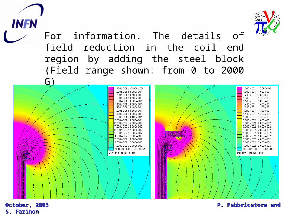
For information. The details of field reduction in the coil end region by adding the steel block (Field range shown: from 0 to 2000 G)

October, 200October, 20033 P. Fabbricatore and S. P. Fabbricatore and S. Farinon Farinon
Question: How much space we have available at the spectrometer coil end?. We remind here the schematic lay-out of the cryostat.

October, 200October, 20033 P. Fabbricatore and S. P. Fabbricatore and S. Farinon Farinon
The following page shows the cryostat ends, as studied till now. The slide shows the general dimensions including the detail of Ti-Al tie rods, attached at the side flange opposite to the end region and passing through the end flange. Vacuum vessel and thermal shields are also shown.
During this study we have understood that the free allowed space for the cryostat is ok along z (and reflecting what Proposal shows). Instead the outer radius shall be around 510 mm (rather than 460). In order to reduce the Cryostat outer radius we shall reduce the radial thickness of the second end coil.

October, 200October, 20033 P. Fabbricatore and S. P. Fabbricatore and S. Farinon Farinon
Ri 200 m m
Re 510
164 m m