nwri-2006-02 mf iv mbr short course abstracts.pdfin mbrs and focuses on topics such as mbr ... 11:05...
TRANSCRIPT


Published by theNational Water Research Institute
NWRI-2006-02
10500 Ellis Avenue • P.O. Box 20865Fountain Valley, California 92728-0865 USA(714) 378-3278 • Fax: (714) 378-3375
www.NWRI-USA.org
A Short Course on
Membrane Bioreactors
iii
Conference Planning Committee
Chair:✦ SAMER S. ADHAM, Ph.D., MWH
✦ SIMON J. JUDD, Ph.D., Cranfield University
✦ GINA MELIN, National Water Research Institute
✦ JEFFREY J. MOSHER, National Water Research Institute
✦ TAMMY RUSSO, National Water Research Institute
Sponsors
The Conference Planning Committee is indebted to the following organizations andcorporations whose support has helped make this conference a success.
✦ NATIONAL WATER RESEARCH INSTITUTE
✦ MWH
✦ CRANFIELD UNIVERSITY
✦ USFILTER
✦ ZENON ENVIRONMENTAL CORPORATION
✦ ORANGE COUNTY WATER DISTRICT
✦ CORONA DEPARTMENT OF WATER AND POWER

iv

A Short Course on
Membrane Bioreactors
v
Foreword
MICROFILTRATION IV is the fourth in a series of conferences sponsored by the National
Water Research Institute (NWRI) devoted to low-pressure membrane (microfiltration
and ultrafiltration) applications to water and wastewater treatment.
Since the first NWRI-sponsored Microfiltration Conference in 1994, the technology has
advanced and become a popular alternative to conventional treatment. MICROFILTRATION IV
provides an update on the status of the technology and a focus on critical issues faced by
end-users, such as new applications, regulatory perspectives, operational experiences, and
fouling control.
A special feature of MICROFILTRATION IV is a one-day short course on membrane bioreactors
(MBRs), a promising technology that uses microfiltration to enhance the wastewater and
reclaimed water treatment processes. The short course provides information on the state-of-the-art
in MBRs and focuses on topics such as MBR design, procurement issues, and costs.
The extended abstracts presented in this document were the contributions of conference speakers.
The opinions expressed within the abstracts are those of individual authors and do not
necessarily reflect those of the sponsors.
NWRI gratefully acknowledges the efforts of all those involved with the planning, organizing,
and sponsoring the conference, including MWH, Cranfield University, USFilter, Zenon
Environmental Corporation, the Corona Department of Water and Power, and Orange County
Water District. NWRI also extends special thanks to the conference moderators and speakers,
whose expertise provided invaluable insight into the status and needs of membrane technology.
NWRI would also like to extend sincere thanks to Gina Melin, Editor, and Tim Hogan,
Graphic Designer, for their efforts in bringing this document to press and ensuring that the
quality of each and every abstract reached their fullest potential.
Lastly, this conference would not have been possible without the vision of Ronald B. Linsky,
Executive Director of NWRI until his passing in August 2005. Ron will be fondly
remembered for his energy, enthusiasm, and dedication to NWRI and the water community.
Jeffrey J. MosherActing Executive DirectorNational Water Research InstituteFountain Valley, California

vi

A Short Course on
Membrane Bioreactors
vii
Program and Contents
WEDNESDAY, MARCH 22, 2006
7:00 am - 9:00 am Registration Foyer of California Ballroom
Session 1: Introduction California BallroomModerated by JEFFREY J. MOSHER, National Water Research Institute, California
8:30 am - 8:45 am WelcomeJEFFREY J. MOSHER, National Water Research Institute, California
8:45 am - 9:15 am Membrane Bioreactors and . . . . . . . . . . . . . . . . . . . . . . . . . . . . . 1the Future of Wastewater Treatment
R. RHODES TRUSSELL, Ph.D., P.E., DEE,
Trussell Technologies, Inc., California
9:15 am - 9:45 am Biological Process Principles . . . . . . . . . . . . . . . . . . . . . . . . . . . . 3GEORGE TCHOBANOGLOUS, Ph.D., P.E.,
University of California, Davis, California
9:45 am - 10:00 am Break
Session 2: Fundamentals and ApplicationsModerated by SAMER S. ADHAM, Ph.D., MWH, California
10:00 am - 10:45 am Membrane Bioreactor Process Fundamentals . . . . . . . . . . . . . . 5SIMON J. JUDD, Ph.D., Cranfield University, England
10:45 am - 11:05 am Commercially Available Membrane Bioreactor Systems . . . . . . 11JAMES F. DECAROLIS, MWH, California
11:05 am - 11:25 am Evaluation of Conventional Activated Sludge . . . . . . . . . . . . . . 19Compared to Membrane Bioreactors
R. SHANE TRUSSELL, Ph.D., P.E.,
Trussell Technologies, Inc., California
11:25 am - 11:45 am Membrane Bioreactor Global Knowledgebase . . . . . . . . . . . . . . 25GLEN T. DAIGGER, Ph.D., P.E., BCEE, NAE,
CH2M HILL, Colorado
11:45 am - 12:15 pm Panel Discussion
12:15 pm - 1:30 pm Lunch The Atrium

viii
Session 3: Case Studies – Real-World Issues with Membrane BioreactorsModerated by GEORGE TCHOBANOGLOUS, Ph.D., P.E.,
University of California, Davis, California
1:30 pm - 2:00 pm Design, Procurement, and Costs of. . . . . . . . . . . . . . . . . . . . . . . 29Membrane Bioreactor Systems
STEPHEN M. LACY, P.E., DEE, MWH, Nevada
2:00 pm - 2:20 pm Retrofit of an Existing . . . . . . . . . . . . . . . . . . . . . . . . . . . . . . . . . . 33Conventional Wastewater Treatment Plant withZenon Membrane Bioreactor Technology
DAVE N. COMMONS,City of Redlands Municipal Utilities Department, California
2:20 pm - 2:40 pm Retrofit of an Existing . . . . . . . . . . . . . . . . . . . . . . . . . . . . . . . . . . 37Conventional Wastewater Treatment Plantwith USFilter Membrane Bioreactor Technology
JOHN HATCHER, Oconee County Utility Department, Georgia
2:40 pm - 3:20 pm Membrane Bioreactor Applications: A Global Perspective . . . . 39SIMON J. JUDD, Ph.D., Cranfield University, England
3:20 pm - 3:45 pm Panel Discussion
3:45 pm - 4:00 pm Break
Session 4: Innovative Applications and Future Outlook of the TechnologyModerated by R. RHODES TRUSSELL, Ph.D., P.E., DEE
Trussell Technologies, Inc., California
4:00 pm - 4:30 pm Membrane Aeration, Biofilms, . . . . . . . . . . . . . . . . . . . . . . . . . . . 43and Membrane Bioreactors
MICHAEL J. SEMMENS, Ph.D., P.E.,
University of Minnesota, Minnesota
4:30 pm - 4:50 pm Future Outlook on Membrane Bioreactor Technology . . . . . . . 45SIMON J. JUDD, Ph.D., Cranfield University, England
4:50 pm - 5:15 pm Panel Discussion
5:15 pm Short Course on Membrane Bioreactors Adjourns
THURSDAY, MARCH 23, 2006 ~ FIELD TRIPS
8:30 am - 11:30 am Field Trips
Those who are attending field trips must turn in field trip passes prior to bus departure. Please check inat the Foyer of the California Ball Room at least 30 minutes prior to departure.
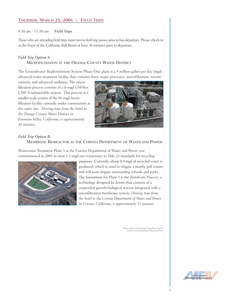
Field Trip Option A:MICROFILTRATION AT THE ORANGE COUNTY WATER DISTRICT
The Groundwater Replenishment System Phase One plant is a 5-million gallon per day (mgd)advanced water treatment facility that contains three major processes: microfiltration, reverseosmosis, and advanced oxidation. The micro-filtration process consists of a 6-mgd USFilterCMF-S submersible system. This process is asmaller-scale version of the 86-mgd micro-filtration facility currently under construction atthe same site. Driving time from the hotel tothe Orange County Water District inFountain Valley, California, is approximately20 minutes.
Field Trip Option B:MEMBRANE BIOREACTOR AT THE CORONA DEPARTMENT OF WATER AND POWER
Wastewater Treatment Plant 3 at the Corona Department of Water and Power wascommissioned in 2001 to treat 1.1-mgd raw wastewater to Title 22 standards for recycling
purposes. Currently, about 0.4 mgd of recycled water isproduced, which is used to irrigate a nearby golf courseand will soon irrigate surrounding schools and parks.The foundation for Plant 3 is the ZenoGem Process, atechnology designed by Zenon that consists of asuspended growth biological reactor integrated with amicrofiltration membrane system. Driving time fromthe hotel to the Corona Department of Water and Powerin Corona, California, is approximately 35 minutes.
A Short Course on
Membrane Bioreactors
ix
Photos courtesy of the Orange County Water District,and the Corona Department of Water and Power

x

Abstracts
A Short Course on
Membrane Bioreactors
xi

xii

A Short Course on
Membrane Bioreactors
1
Correspondence should be addressed to:
R. Rhodes Trussell, Ph.D., P.E., DEEPresidentTrussell Technologies, Inc.232 North Lake Avenue, Suite 300Pasadena, CA 91101-1862 USAPhone: (626) 486-0560 • Email: [email protected]
Session 1: Introduction
Membrane Bioreactors and the Future of Wastewater Treatment
R. RHODES TRUSSELL, PH.D., P.E., DEE
Trussell Technologies, Inc.Pasadena, California
Adecade ago, membrane bioreactors (MBRs) weren’t even on our radar screen. Today,MBRs are the process of choice for small-scale reuse projects with demands for high
water quality. Projects are popping up everywhere. Soon, MBRs will change the way we thinkabout treatment for reuse, opening a new era of decentralized treatment. In the very long-term, just as membrane filtration will replace granular media filtration, MBRs will replaceconventional biological processes that depend on gravity sedimentation or granular mediafiltration for solids separation.
What is the appeal of the MBR? What are some of the limits of the process? How is ourthinking about MBRs changing, and how will it change in the future? What problems mustwe solve for MBRs to reach their full potential? What can MBRs do to help us meet futureregulations?
The most obvious appeal of the MBR is that it produces an excellent effluent quality. Thecompactness of the MBR is another important element in its appeal. Finally, the MBR hasgreat potential for automation. Important to both the design engineer and operator, the MBReliminates the need for good sludge settleability as a central requirement. Effluent quality isless sensitive to operations, and precise control of the sludge residence time (SRT)/mixedliquor suspended solids (MLSS)/food to microorganisms (F:M) ratio is not as important.Finally, the MBR puts much greater distance between reclamation and the risk of microbialdisease. Pathogens are not just reduced by a highly selective chemical or photochemicalreaction, they are rejected by size exclusion. The MBR also makes longer SRTs feasible in acompact space, resulting in less biomass to waste, the removal of a broader variety of resistantcompounds, and a more biostable effluent with a lower oxidant demand. Finally, the MBRproduces an effluent that is immediately suitable for reverse osmosis treatment, should that bea requirement.
In today’s world, there are two kinds of issues that we face in making decision about thedeployment of MBRs:
Type I Issues — Issues that must be resolved to improve reliability, cost, and/orperformance.
Type II Issues — Issues that are inherent to the process and must be understood bydesigners and operators of successful MBR projects.

Examples of Type I issues are: (a) understanding the upper limits of the MLSS that theprocess can handle and how the reactor configuration affects this, (b) understanding the lowerlimits of SRT and hydraulic residence time (HRT), (c) the optimization of air scouring andenergy consumption, (d) membrane cleaning, (e) design and operational practices that willextend membrane life, and (f) designing and operating the MBR process to optimize sludgefilterability.
Examples of Type II issues are the design and operation requirements imposed by the impactthat fouling can have on hydraulic performance, by MBR’s limited ability to handle peaking,and on MBRs by reduced oxygen transfer at high MLSS.
To date, most MBR installations have been small enough that it has basically been possible toignore the biology. This will not do in the future. The future belongs to those who take fulladvantage of all that we have learned about the behavior of this complex biological system andintegrate it with the unique capabilities and limitations of MBRs. Some examples of problemsthat must be addressed include:
• The management of organisms associated with foaming.
• The management of the biological system to produce a sludge that is easilyfiltered and dewatered.
• The full integration of what we know about nutrient removal with the MBRprocess.
In the meantime, there are places where MBR is attractive today, even for the conservativeengineer. MBR is most appealing when its small footprint, ease of automation, and excellenteffluent quality are all requirements. It is also most appealing when flow peaking can beeasily addressed. Reuse projects that scalp the flow from nearby sewers are one of the moreobvious examples. Moreover, MBR has the potential to rearrange our thinking about reuse.There are limits to the idea of pumping treated wastewater up into and throughout acommunity in purple pipe. MBR creates the potential for decentralized reuse systems withtreatment systems located closer to the point of application and smaller, less-intrusive purpleinfrastructure.
2
R. RHODES TRUSSELL, Ph.D., P.E., DEE, is recognized worldwide as an authorityin methods and criteria for water quality and in the development of advancedprocesses for treating water or wastewater to achieve the highest standards. A Civiland Corrosion Engineer with 35 years of experience, he has worked on the processdesign for dozens of treatment plants ranging in size from 1 to 900 million gallons perday in capacity. At present, he is President of Trussell Technologies, Inc., anenvironmental engineering firm that focuses on the quality and treatment of waterand wastewater. He is also active on numerous boards and committees, such asserving as Chair of the Water Science and Technology Board for the National Academies. Just recently,he retired from the U.S. Environmental Protection Agency’s Science Advisory Board after 17 years ofservice. Trussell received a B.S. in Civil Engineering and both an M.S. and Ph.D. in SanitaryEngineering from the University of California, Berkeley.

A Short Course on
Membrane Bioreactors
3
Correspondence should be addressed to:
George Tchobanoglous, Ph.D., P.E.Professor Emeritus of Civil and Environmental EngineeringUniversity of California, Davis662 Diego PlaceDavis, CA 95616 USAPhone: (530) 756-5747 • Email: [email protected]
Session 1: Introduction
Biological Process Principles
GEORGE TCHOBANOGLOUS, PH.D., P.E.
University of California, DavisDavis, California
With proper analysis and environmental control, almost all wastewaters containingbiodegradable constituents can be treated biologically. Therefore, it is essential that the
environmental engineer understand the characteristics of each biological process to ensurethat the proper environment is produced and controlled effectively. The overall objectives ofthe biological treatment of domestic wastewater are to:
• Transform (i.e., oxidize) dissolved and particulate biodegradable constituents intoacceptable end-products.
• Capture and incorporate suspended and nonsettleable colloidal solids into a biologicalfloc or biofilm.
• Transform or remove nutrients, such as nitrogen and phosphorus.
• More recently, to remove specific trace constituents and compounds.
For industrial wastewater, the objective is to remove or reduce the concentration of organicand inorganic compounds. Because some of the constituents and compounds found inindustrial wastewater are toxic to microorganisms, pretreatment may be required beforeindustrial wastewater can be discharged to a municipal collection system. For agriculturalirrigation runoff, the objective is to remove nutrients (specifically nitrogen and phosphorus),pesticides, and trace constituents that are capable of affecting the aquatic environment.
The principal biological processes used for wastewater treatment can be divided into threemain categories: suspended growth, attached growth (or biofilm), and combined suspended andattached growth processes. The successful design and operation of the biological processesrequires an understanding of the:
• Types of microorganisms involved.
• Specific reactions that they perform.
• Environmental factors that affect their performance.
• Nutritional needs of microorganisms.
• Microorganism reaction kinetics.
These subjects are reviewed in light of process developments that have occurred over the pastcentury.

4
For over 35 years, wastewater expert GEORGE TCHOBANOGLOUS, PH.D., P.E.,has taught courses on water and wastewater treatment and solid waste managementat the University of California, Davis, where he is Professor Emeritus in the Depart-ment of Civil and Environmental Engineering. He has authored or coauthored over350 publications, including 13 textbooks and five engineering reference books.Tchobanoglous has been past President of the Association of EnvironmentalEngineering and Science Professors and currently serves as a national and inter-national consultant to both government agencies and private concerns. Among hishonors, he received the Athalie Richardson Irvine Clarke Prize from the National Water ResearchInstitute in 2003 and was inducted to the National Academy of Engineers in 2004. In 2005, hereceived an Honorary Doctor of Engineering degree from the Colorado School of Mines.Tchobanoglous received a B.S. in Civil Engineering from the University of the Pacific, an M.S. inSanitary Engineering from the University of California, Berkeley, and a Ph.D. in EnvironmentalEngineering from Stanford University.

A Short Course on
Membrane Bioreactors
5
Correspondence should be addressed to:
Simon J. Judd, Ph.D.Professor in Membrane Technology and Director of Water SciencesBuilding 61Cranfield UniversityBedfordshire MK43 0AL United KingdomPhone: (+44) (0)1234 754173 • Email: [email protected]
Session 2: Fundamentals and Applications
Membrane Bioreactor Process Fundamentals
SIMON J. JUDD, PH.D.
Cranfield UniversityBedfordshire, United Kingdom
Introduction
The use of microfiltration (MF) or ultrafiltration (UF) membranes in biological wastewatertreatment has been well documented and extensively reviewed. Membrane filtration
produces a high-quality, clarified, and disinfected permeate product. It also permits absolutecontrol of solids retention time (SRT) and, thus, correspondingly, control of the mixed liquorsuspended solids (MLSS) concentration. This both reduces the required reactor size andpromotes the development of specific nitrifying bacteria, thereby enhancing ammonia removal,as well as producing less sludge.
However, as with almost all other membrane processes, the production rate of membranebioreactors (MBRs) is ultimately limited by membrane fouling. Fouling arises from theaccumulation of solute, colloidal, and particulate species on or within the membrane, leadingto a deterioration in membrane permeability. This phenomenon has led to the developmentof the low-fouling submerged configuration, first introduced 15 years ago, as opposed tosidestream systems, wherein the membrane is immersed in the bioreactor rather than fittedexternal to it (Figure 1). Submerged systems tend to allow greater hydraulic efficiencies,reflected in greater permeabilities, due to their operation at substantially lower fluxes thansidestream systems (Table 1), since fouling tends to increase with increasing flux.
Out(membrane fouling)
Bioreactor(Activity + Nature)
Feed(Screens)
Air(Energy)
Sludge Waste(Quantity and Quality)
Figure 1. Elements of a membrane bioreactor.

Table 1. Summary of Membrane Bioreactor Process Conditions for Sewage Treatment
Mitsubushi Orelis or Parameter Kubota Rayon Zenon Wehrle
Membrane Geometry FS HF HF MT
Process Configuration Submerged Submerged Submerged Side-stream
Mean Air Velocity (m/s) 0.05 0.03 0.1 –
Mean Liquid Velocity (m/s) 0.5* – – 1-3
TMP (bar) 0.05-0.15 0.1-0.5 0.1-0.5 2-5
Flux (LMH) ~25 ~15 ~25 70-100
FS = Flat sheet. HF = Hollow fiber. MT = Multitube. LMH = Liters per cubic meter per hour. TMP= Transmembrane pressure. m/s = Meters per second. *As quoted by supplier.
Fouling
Fouling is a particularly acute problem in the case of MBRs, since the membrane is challengedwith highly contaminated liquors having total solids concentrations of 20 grams per liter (g/L) ormore arising from concentrated biomass. A second limitation, clogging – which refers to thefilling of the membrane interstices with solids – is generally of less significance, but must stillbe suppressed for successful operation. There are a number of elements of a submerged MBRsystem (see Figure 1), all contributing to varying degrees of fouling and clogging, and theirinterrelationship is complex (Figure 2).
In considering fouling and its causes and implications, the various elements of the system(see Figure 1) can be discussed in turn. Firstly, there are the feed characteristics. Variousbiochemical transformations in the bioreactor convert the organic matter in the feed into largely
6
Operation
Biomass Characteristics
Fouling Clogging
AerationMembrane Module Characteristics
Retention Time
Hydraulics
Cleaning
Feed Characteristics
Bulk Characteristics• Viscosity/Rheology• Hydrophobicity
Floc Characteristics • Size • Structure
EPS• Free• Bound
Reversible IrreversibleMembraneChannels
AeratorPorts
Configuration• Geometry• Dimensions
• Design (Port Size)• Mean Flow Rate• Pulse Rate
• Physical• Chemical
• Flux• TMP
• Hydraulic• Solids
Pore• Size• Shape
Surface Characteristics• Porosity• Charge/Hydrophobicity
Figure 2. Inter-relationships between membrane bioreactor parameters and fouling.

mineralized products, principally carbon dioxide and nitrate. In doing so, a variety of materialsare released from the biomass in the reactor, which are collectively referred to as extracellularpolymeric substances (EPS) and which contain a number of components that can foul themembrane to various extents. The relative and overall concentrations of the various componentsare determined both by feed characteristics and operational facets of the system and, inparticular, by microbial speciation. Other foulants originate directly from unbiodegradedcomponents of the feedwater, particularly for feeds of low biodegrability.
Secondly, there is the actual process design and configuration of the MBR process, which inturn affects the key operator parameter values chosen. Submerged MBRs operate at lowerfluxes and, as a result, lower transmembrane pressure (TMP) values (and so permeabilities)than the sidestream configuration. Therefore, they are inherently higher in energy efficiency,manifested as the specific energy demand in kilowatt-hour per cubic meter (kWh/m3)permeate product. The configuration of the membrane module — principally, the membraneelement geometry (planar or cylindrical), material physical properties (pore size, tortuosity,hydrophobicity, and surface porosity), and chemistry (polymeric or ceramic) — can alsoinfluence fouling. Although there are now a number of proprietary MBR technologies in themarketplace, the majority of them are based either on a flat sheet (FS) membraneconfiguration or on hollow fibers (HF).
Thirdly, the operation of the MBR can profoundly impact fouling. There are two componentsof MBR operation: the membrane and the bioreactor. The bioreactor component (as with aconventional activated sludge process) is controlled by the relative values of the retention ofsolids and liquid (i.e., the solids [SRT] and hydraulic [HRT] retention times). Increasing theSRT and decreasing the HRT leads to higher levels of suspended solids (usually referred to asmixed liquor suspended solids [MLSS]) in the bioreactor, which increases the risk of cloggingin both the membrane interstices and aerator ports. However, the impact of retention timeson fouling is normally not significant in sewage treatment provided the MLSS is kept within arange of values in which fouling and foaming are suppressed (which tends to prevail at lowMLSS values of around 4 to 6 g/L) and clogging is avoided by operating below a thresholdMLSS value (which depends largely upon the membrane configuration). The maindeterminants for fouling control, however, relate directly to the membrane itself.
Fouling Control
In submerged MBRs, generally only three strategies are available for limiting fouling withregards to operation: reducing the flux, increasing aeration, or employing physical or chemicalcleaning. Coarse bubble aeration produces scouring action at the surface of the membrane,which limits the build-up of foulant material. Lowering the flux reduces the rate at whichfoulants arrive at the membrane. However, both these modifications have cost implications,since a reduced flux implies a greater membrane area requirement and energy demandincreases roughly linearly with increasing air flow rate. Cleaning demands downtime, andmore rigorous cleaning using chemicals exerts chemical demand and produces chemical waste.A good operation of submerged MBR systems is based on obtaining the appropriate balancebetween operational flux, aeration, and cleaning. It follows that good MBR design is associa-ted with maximizing the impact of aeration (in terms of reducing fouling) and facilitatingcleaning with minimal downtime and chemicals consumption, as well as providing a highmembrane area at low cost so as to permit a low flux.
The constraints imposed by the challenging environment in which the membranes operatehave meant that the municipal wastewater treatment MBR market is dominated by just two
A Short Course on
Membrane Bioreactors
7

designs: the HF membrane-based product (Zenon) and the FS (Kubota). Much debate existsas to the relative merits offered by these two designs. The flat plate configuration tends to runat slightly higher permeabilities (flux per unit TMP) and is simpler in operation. On the otherhand, unlike the HF, it cannot be backflushed. Both systems appear to maintain reasonablefluxes by applying relaxation – intermittent physical cleaning attained simply by closing thepermeate valve and allowing air to scour the membrane surface. Both Kubota and Zenon havealso recently developed design modifications for increasing efficiency. In the case of Kubota,this is achieved by stacking the membrane modules (already employed by Mitsubishi Rayon inits MBRs based on its Sterapore HF membrane). Zenon has introduced intermittent aeration,which effectively halves the specific energy demand associated with aeration, the mainoperating cost component.
Technologies
There are an increasing number of commercial MBR technologies, many of which are listed inTables 2 and 3. It appears that almost all immersed MBRs are either rectangular FS or HF,and that most sidestream MBR technologies are multi-tubes (MT). The exceptions to thesegeneral observations appear to be:
a. The Orelis Pleaide FS membrane used for sidestream treatment.
b. The Polymem and Ultraflo sidestream HF systems.
c. The hexagonal/octagonal rotating immersed Huber FS membrane.
d) The Millenniumpore MT membrane, which has been used as an immersed module,as well as for air-lift sidestream.
8
Process Configuration
MembraneConfiguration
Immersed Sidestream
FS Colloide Novasep-OrelisBrightwater
Huber*ITRI NWF
KubotaMicrodyn Nadir
Toray
HF Asahi-kasie PolymemHan-S Environmental Ultraflo
ITTKoch/Puron
KolonMitsubishi Rayon
MotimoSiemens/USF-Memcor
Zenon
MT Millenniumpore Berghof**MillenniumporeNorit-Xflow**
*Rotating membrane.**MT membrane products used by process suppliers such as Aquabio, Dynatec, Triqua, and Wehrle.
Table 2. Commercial Technologies

Table 3. Commercial Membrane Product Specifications
Membrane Pore Specific Propietary Name,Supplier (Configuration, Size Surface Membrane,
Material) (µm) Area � (m-1) or Module
Berghof MT, PES 0.08 110 HyPerm-AEor PVDF 0.12 Hyperflux
Brightwater FS, PES 0.08 110 Membright
Toray FS, PVDF 0.08 130 Toray
Kubota FS, PE 0.4 150 Kubota
Colloide FS, PES 0.04 160 Sub Snake
Huber FS, PES 0.038 160 VRM
Millenniumpore MT, PES 0.1 180 Millenniumpore
Koch HF, PES 0.05 260 Puron
Zenon HF, PVDF 0.04 300 ZW500C-D
Norit-Stork MT, PVDF 0.038 320 F4385290 F5385
Mitsubishi Rayon HF, PE 0.4 425 SUR
HF, PVDF 0.4 333 SADF
USF-Memcor HF, PVDF 0.04 600-700 B10R, B30R
Asahi-kasie HF, PVDF 0.1 710 Microza
Polymem HF, PS 0.08 800 WW120
Motimo HF, PVDF 0.1-0.2 1100 Flat Plat
Moreover, almost all HF MBR membrane products currently on the market are vertically-mounted and polyvinylidene difluoride (PVDF)-based, the exceptions being the Koch-Puronmembrane (which is polyethersulphone [PES]), the Polymem polysulfone (PS) membrane,and the Mitsubishi Rayon SUR module (which is polyethylene [PE] material and alsohorizontally oriented). All HF products are in the coarse UF/tight MF region of selectivity,having pore sizes predominantly between 0.03 and 0.4 micrometers (µm), and all suchvertically-mounted systems are between 0.7 and 2.5 millimeters (mm) in external diameter.Distinctions in HF MBR systems can be found mainly in the use of membrane reinforcement(essential for those HF elements designed to provide significant lateral movement) and,perhaps most crucially, the air-to-membrane contact.
A Short Course on
Membrane Bioreactors
9
10
PROFESSOR SIMON JUDD is the Director of Water Sciences at CranfieldUniversity. He has been on the staff at the School of Water Sciences since August1992, and occupies the Chair in Membrane Technology. Judd has managed almostall biomass separation membrane bioreactor (MBR) programs conducted within theSchool and has been Principal or Co-Investigator on three major UK researchcouncil-sponsored programs dedicated to MBRs with respect to in-building waterrecycling, sewage treatment, and contaminated groundwater/landfill leachate. Healso serves as Chairman of the Project Steering Committee of the multi-centeredEU-sponsored EUROMBRA project. In addition to publishing extensively in the research literature,Judd has co-authored two textbooks in membrane and MBR technology, with a third one due out in July2006. Judd received a B.Sc. in Chemistry from the University of Bath, M.Sc. in ElectrochemicalScience from Southampton University, and a Ph.D. in Filtration Science from Cranfield University.
A Short Course on
Membrane Bioreactors
11
Correspondence should be addressed to:
James F. DeCarolisMWH Americas, Inc.Aqua 2030 Research CenterNorth City Water Reclamation Plant4949 Eastgate MallSan Diego, CA 92121 USAPhone: (858) 824-6067 • Email: [email protected]
Session 2: Fundamentals and Applications
Commercially Available Membrane Bioreactor Systems
JAMES F. DECAROLIS
MWHSan Diego, California
ZAKIR HIRANI
MWHSan Diego, California
SAMER S. ADHAM, PH.D.
MWHPasadena, California
NEIL TRAN, P.E.
City of San DiegoSan Diego, California
STEVE LAGOS
City of San DiegoSan Diego, California
Introduction
The following paper provides a detailed description of four commercially availablemembrane bioreactor (MBR) systems currently established in the municipal wastewater
treatment/water reclamation market in the United States. These systems are supplied byZenon Environmental, Inc., USFilter, Ionics/Mitsubishi Rayon Corporation, and Enviroquip, Inc./Kubota Corporation. Each of these suppliers has full-scale MBRs currently operating in theUnited States, and their systems are approved by the California Department of HealthServices (CDHS) to meet Title 22 water recycling criteria. Details of each system are basedon knowledge gained during hands-on pilot testing performed by the project team along withinformation provided by the manufacturers. The paper will also describe four newly developedMBR systems currently entering the United States market. These suppliers include KochMembrane Systems (KMS), Kruger, Parkson Corporation, and Huber, Inc. The project teamis currently evaluating the ability of these new technologies to meet Title 22 recycling criteriaunder grant funding provided by the United States Department of Interior, Bureau of
Reclamation. Lastly, the paper discusses MBR pilot-testing considerations based on nearly adecade of MBR research performed by the project team at the Aqua 2030 Research Centerlocated in San Diego, California.
Commercially Available Membrane Bioreactor Systems(Established in the United States)
Zenon Membrane Bioreactor System
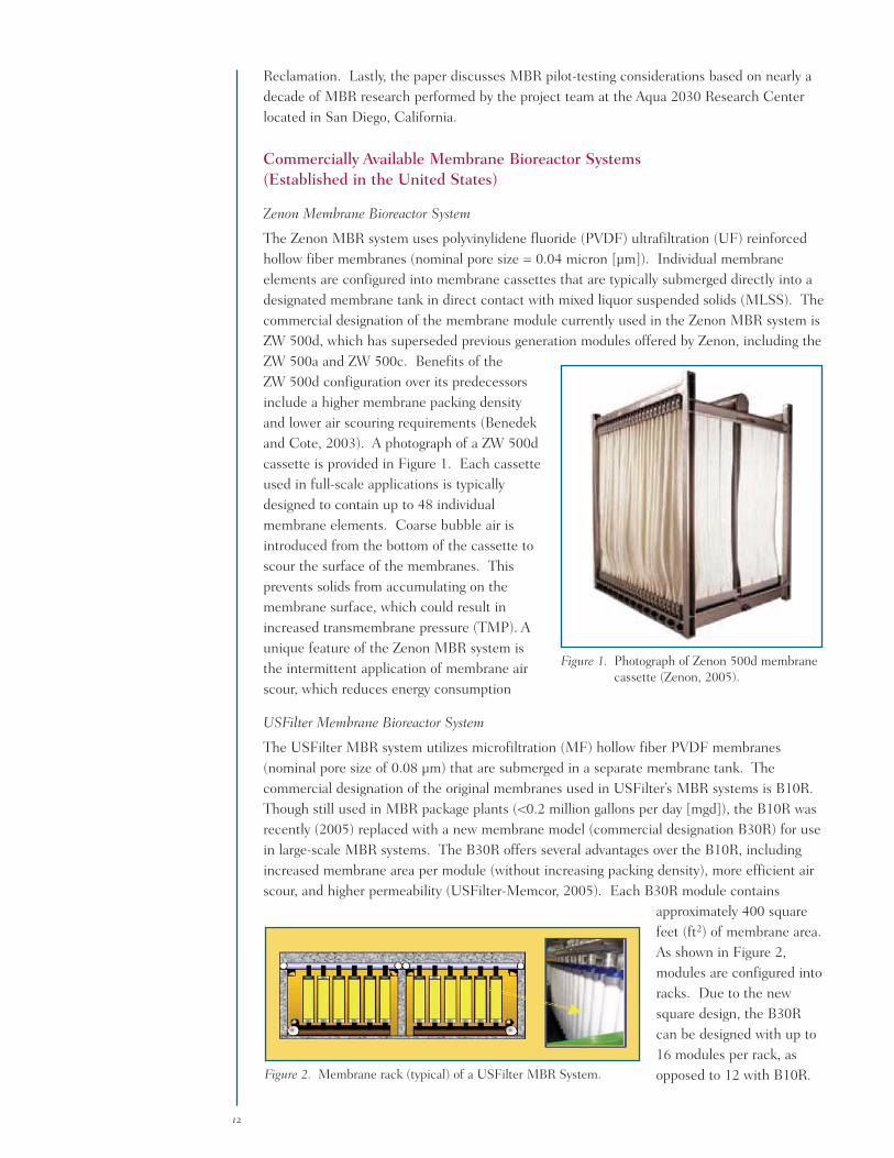
The Zenon MBR system uses polyvinylidene fluoride (PVDF) ultrafiltration (UF) reinforcedhollow fiber membranes (nominal pore size = 0.04 micron [µm]). Individual membraneelements are configured into membrane cassettes that are typically submerged directly into adesignated membrane tank in direct contact with mixed liquor suspended solids (MLSS). Thecommercial designation of the membrane module currently used in the Zenon MBR system isZW 500d, which has superseded previous generation modules offered by Zenon, including theZW 500a and ZW 500c. Benefits of theZW 500d configuration over its predecessorsinclude a higher membrane packing densityand lower air scouring requirements (Benedekand Cote, 2003). A photograph of a ZW 500dcassette is provided in Figure 1. Each cassetteused in full-scale applications is typicallydesigned to contain up to 48 individualmembrane elements. Coarse bubble air isintroduced from the bottom of the cassette toscour the surface of the membranes. Thisprevents solids from accumulating on themembrane surface, which could result inincreased transmembrane pressure (TMP). Aunique feature of the Zenon MBR system isthe intermittent application of membrane airscour, which reduces energy consumption
USFilter Membrane Bioreactor System
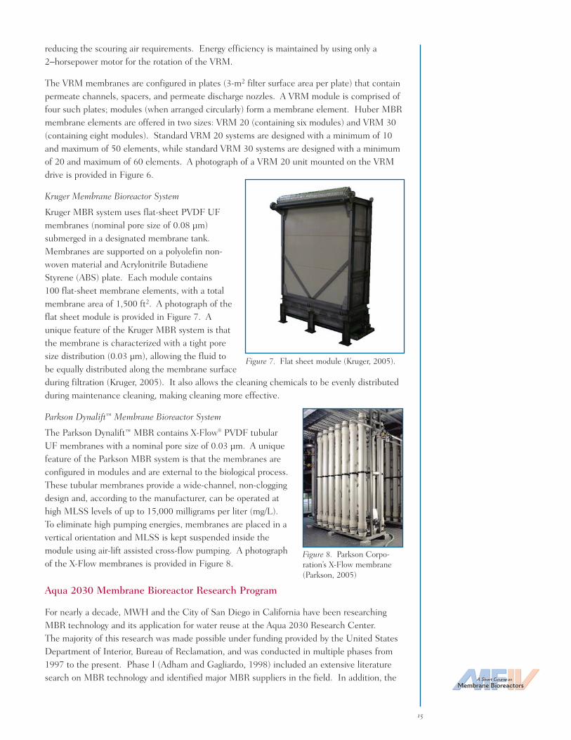
The USFilter MBR system utilizes microfiltration (MF) hollow fiber PVDF membranes(nominal pore size of 0.08 µm) that are submerged in a separate membrane tank. Thecommercial designation of the original membranes used in USFilter’s MBR systems is B10R.Though still used in MBR package plants (<0.2 million gallons per day [mgd]), the B10R wasrecently (2005) replaced with a new membrane model (commercial designation B30R) for usein large-scale MBR systems. The B30R offers several advantages over the B10R, includingincreased membrane area per module (without increasing packing density), more efficient airscour, and higher permeability (USFilter-Memcor, 2005). Each B30R module contains
approximately 400 squarefeet (ft2) of membrane area.As shown in Figure 2,modules are configured intoracks. Due to the newsquare design, the B30Rcan be designed with up to16 modules per rack, asopposed to 12 with B10R.
12
Figure 1. Photograph of Zenon 500d membranecassette (Zenon, 2005).
Figure 2. Membrane rack (typical) of a USFilter MBR System.

A unique feature of the USFilter MBR system is that it incorporates MemJet™ technology,which includes the injection of both air and mixed liquor at the bottom of the membranemodules. This operation causes the membranes to be scoured and fluidized and preventsparticulate matter from accumulating on the membrane surface.
Ionics/Mitsubishi Rayon Membrane Bioreactor System
The Ionics/Mitsubishi Rayon MBR system usespolyethylene MF hollow fiber membranes (nominalpore size of 0.4 µm) that are submerged directlyin an aeration basin. The commercial designationfor the membranes is Sterapore HF. Thoughclassified as MF, the membranes are characterizedwith a tight pore size distribution (absolute poresize= 0.5 µm). As shown in Figure 3, eachmembrane cassette contains individual hollowfibers membranes configured horizontally to makeup an element. Each membrane cassette contains50 of the 1-square meter (m2) MitsubishiSterapore HF MF membranes, for a totalmembrane area of 100 m2 (1,076 ft2). Air issupplied at the bottom of the tank for scour andbiological process. During filtration, vacuumpressure is applied, causing water to permeate through the membrane from the top and bottom.
Kubota Membrane Bioreactor System
The Kubota MBR system contains flat sheet, chlorinated polyethylene MF membranes (nominalpore = 0.4 µm) that are submerged directly in an aeration basin. The commercial designationof the flat sheet membrane cartridge is Type 510. Each cartridge is 1 m (H) x 0.49 m (W) x6 millimeters (mm) thick, and contains a membrane surface area of 0.8 m2. A photograph of
the Type 510 membrane cartridge is provided inFigure 4. Each cartridge contains a supportplate, spacer, permeate nozzle, and membranelayer on each side. Recently (2005), Kubotaintroduced a Type 515 membrane cartridgeprimarily for applications of 2 mgd or greater.The Type 515 cartridges are larger in dimensionthan Type 510 cartridges, resulting in increasedmembrane area per cassette. The Type 510cassette contains up to 150 individual cartridges(spaced 7 mm apart) and is equipped with apermeate manifold. During filtration, permeatewater flows out of the cartridges through thepermeate nozzle and into collection tubes thatfeed into the permeate manifold. A unique
feature of the Kubota MBR system is that can be designed as a single or double deck (DD)configuration. The DD systems contain both upper and lower membrane cassettes. Thelower cassettes are equipped with a coarse air bubble diffuser and provide structural supportto the upper casts. This DD configuration offers several benefits (van der Roest et al, 2002),including the reduction of 1) the membrane footprint, 2) the biological volume consumed by
A Short Course on
Membrane Bioreactors
13
Figure 3. Mitsubishi Sterapore HF membranecassette.
Figure 4. Kubota Type 510 membrane cassette.

the membrane system, and 3) air consumption used for membrane cleaning. The DD alsoyields a more controllable biological process and reduces the possibility of short circuiting.
Newly Developed Membrane Bioreactor Systems
Koch Membrane Systems Membrane Bioreactor System
The KMS membrane bioreactor uses PURON® hollow fiber UF membranes (nominal poresize = 0.05 µm) that are made of polyethersulfone (PES) and casted onto a braided support.The hollow fiber membranes are configured in bundles to form membrane modules and aresubmerged in a designated membrane tank. A unique feature of the KMS MBR is that eachmembrane is sealed at the top and potted only at the lower end. This design allows the non-potted ends to move freely in the MLSS, which eliminates the possibility of clogging. An airnozzle is located in the center of each bundle to provide membrane air scour. A standardmodule contains nine membrane bundles for a total membrane area of 30 m2. The PURONhollow fiber module is shown in Figure 5.
Huber Membrane Bioreactor System
The Huber MBR system uses flat sheet UF membranes (nominal pore size= 0.038 µm)submerged in a designated membrane tank. A unique feature of the Huber MBR system isthat the membranes are supported on a Vacuum Rotation Membrane (VRM®) unit, whichconsists of individual rotating VRM plate membranes installed around a stationary hollowshaft. Two centrally arranged air tubesintroduce scouring air into the inter-spaces between the plates. Permeateis drawn from the each plate viapermeate tubes that collect permeateto a common pipe. These horizontalpipes meet at a center manifold, fromwhich the permeate exits the system.The constant rotation (1.8 revolutionsper minute [RPM]) of the VRM unitallows the membrane plates to be airscoured alternatively by just twocentrally placed air tubes, thereby
14
Figure 5. PURON membrane module (Koch Membrane Systems, 2005).
Figure 6. Huber VRM unit (plan view).
reducing the scouring air requirements. Energy efficiency is maintained by using only a2−horsepower motor for the rotation of the VRM.
The VRM membranes are configured in plates (3-m2 filter surface area per plate) that containpermeate channels, spacers, and permeate discharge nozzles. A VRM module is comprised offour such plates; modules (when arranged circularly) form a membrane element. Huber MBRmembrane elements are offered in two sizes: VRM 20 (containing six modules) and VRM 30(containing eight modules). Standard VRM 20 systems are designed with a minimum of 10and maximum of 50 elements, while standard VRM 30 systems are designed with a minimumof 20 and maximum of 60 elements. A photograph of a VRM 20 unit mounted on the VRMdrive is provided in Figure 6.
Kruger Membrane Bioreactor System
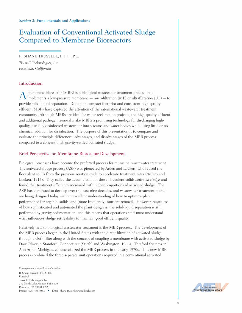
Kruger MBR system uses flat-sheet PVDF UFmembranes (nominal pore size of 0.08 µm)submerged in a designated membrane tank.Membranes are supported on a polyolefin non-woven material and Acrylonitrile ButadieneStyrene (ABS) plate. Each module contains100 flat-sheet membrane elements, with a totalmembrane area of 1,500 ft2. A photograph of theflat sheet module is provided in Figure 7. Aunique feature of the Kruger MBR system is thatthe membrane is characterized with a tight poresize distribution (0.03 µm), allowing the fluid tobe equally distributed along the membrane surfaceduring filtration (Kruger, 2005). It also allows the cleaning chemicals to be evenly distributedduring maintenance cleaning, making cleaning more effective.
Parkson Dynalift™ Membrane Bioreactor System
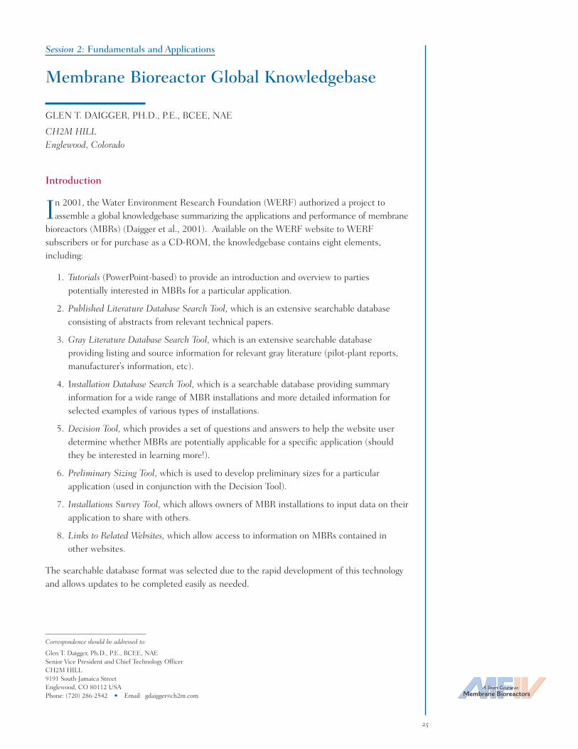
The Parkson Dynalift™ MBR contains X-Flow® PVDF tubularUF membranes with a nominal pore size of 0.03 µm. A uniquefeature of the Parkson MBR system is that the membranes areconfigured in modules and are external to the biological process.These tubular membranes provide a wide-channel, non-cloggingdesign and, according to the manufacturer, can be operated athigh MLSS levels of up to 15,000 milligrams per liter (mg/L).To eliminate high pumping energies, membranes are placed in avertical orientation and MLSS is kept suspended inside themodule using air-lift assisted cross-flow pumping. A photographof the X-Flow membranes is provided in Figure 8.
Aqua 2030 Membrane Bioreactor Research Program
For nearly a decade, MWH and the City of San Diego in California have been researchingMBR technology and its application for water reuse at the Aqua 2030 Research Center.The majority of this research was made possible under funding provided by the United StatesDepartment of Interior, Bureau of Reclamation, and was conducted in multiple phases from1997 to the present. Phase I (Adham and Gagliardo, 1998) included an extensive literaturesearch on MBR technology and identified major MBR suppliers in the field. In addition, the A Short Course on
Membrane Bioreactors
15
Figure 7. Flat sheet module (Kruger, 2005).
Figure 8. Parkson Corpo-ration’s X-Flow membrane(Parkson, 2005)

project team implemented a worldwide survey of full-scale MBR applications for domesticwastewater treatment and developed rough cost estimates for the technology. Informationgathered during the survey included operational characteristics such as capacity, MLSSconcentrations, food-to-microorganism ratio, permeate flux, solids retention time (SRT), andhydraulic retention time (HRT), along with performance in terms of particulate, organic,nutrient, and microbial contaminant removal.
Phase II testing (Adham et al., 2000) included the operation and evaluation of two pilot-scaleMBRs (Zenon and Mitsubishi) over a 1-year period. The purpose of testing was to evaluatethe performance of these systems during the treatment of municipal wastewater and toestablish baseline operating conditions. Towards the end of the pilot-testing period, theproject team worked with CDHS to establish criteria for MBR systems to gain Title 22approval. Based on these criteria, further testing of the Zenon and Mitsubishi systems wasdone in 2001 under funding provided by the National Water Research Institute (Adham et al.,2001a and 2001b). Results from this testing, along with those acquired during the1-year operating period, were submitted to CDHS in September 2001. Shortly after, the twosystems were granted conditional approval to meet Title 22 water recycling criteria.
In June 2002, the project team embarked on Phase III (Adham and DeCarolis, 2004), whichincluded the evaluation of four MBR pilot units (USFilter Corporation/Jet Tech Products Group;Zenon Environmental, Inc.; Ionics/Mitsubishi Rayon Corporation; and Enviroquip Inc./Kubota Corporation). Pilot testing of these systems was conducted over a 16-month period onraw and advanced primary effluent to evaluate MBR performance and to determine thesuitability of MBR effluent as a feed to reverse osmosis units. Data generated during thisstudy demonstrated the ability of the Kubota and USFilter MBR systems to meet Title 22Water Recycling Criteria, and both were granted approval in 2002/2003 (CaliforniaDepartment of Health Services, 2005). In addition, it was shown that MBR systems couldsuccessfully operate on advanced primary treated wastewater containing coagulant andpolymer residual.
Recently, the project team has begun Phase IV (U.S. Department of Interior, Bureau ofReclamation, 2005) of the MBR program. The purpose of this ongoing project is to evaluatefour newly developed MBR systems entering the municipal wastewater market in the UnitedStates. These include systems from Koch Membrane Systems (Wilmington, Massachusetts),Parkson Corporation (Fort Lauderdale, Florida), Huber Technology, Inc. (Huntersville, NorthCarolina), and Kruger (Cary, North Carolina). Each of these systems has been designed withinnovative features aimed to optimize operational performance and efficiency. As part oftesting, each system will be evaluated to meet Title 22 requirements, which (upon approval)would double the number of approved systems available to the water reclamation industry.
Based on the research program described above, the project team has identified severalimportant factors to consider when pilot testing MBR systems for water reuse applications.These include:
• Water Quality Goals (total nitrogen, phosphorus, establish a water quality sampling plan).
• Selecting a Supplier(s) (system configuration, customer support, suppliers experience,capacity of full-scale potential plant, pilot rental fee).
• Pilot Site (access to raw wastewater [20- to 40 gallons per minute]), access to sewer todispose of waste, potable water supply for cleaning, adequate power supply available).
16

• MBR Operating Conditions (flux, HRT, SRT, membrane cleaning frequency [maintenanceand recovery cleans], backwash/relax frequency, recirculation rate for denitrification).
• Special Considerations (pretreatment, operator requirements, duration of testing, posttreatment requirements, operation and maintenance requirements, biological tank mixingrequirements, redundancy and location of feed pumps, wasting, foaming control).
Additional information regarding these considerations will be provided during the conferencepresentation.
References
Adham, S., and P. Gagliardo (1998). Membrane Bioreactors for Water Repurification – Phase I. DesalinationResearch and Development Program Report No. 34, Project No. 1425-97-FC-81-30006J, United StatesDepartment of Interior, Bureau of Reclamation.
Adham, S., R. Mirlo R. and P. Gagliardo (2000). Membrane Bioreactors for Water Reclamation – Phase II.Desalination Research and Development Program Report No. 60; Project No. 98-FC-81-0031, UnitedStates Department of Interior, Bureau of Reclamation.
Adham, S., D. Askenaizer, R. Trussell, and P. Gagliardo (2001a). Assessing the Ability of the Zenon ZenogemMembrane Bioreactor to Meet Existing Water Reuse Criteria, Final Report. National Water ResearchInstitute.
Adham, S., D. Askenaizer, R. Trussell, P. and Gagliardo (2001b). Assessing the Ability of the Zenon MitsubishiSterapore Membrane Bioreactor to Meet Existing Water Reuse Criteria, Final Report. National WaterResearch Institute.
Adham, S., and J. DeCarolis (2004). Optimization of Various MBR Systems for Water Reclamation – Phase III.Final Report Project No. 01-FC-81-0736, Bureau of Reclamation.
Benedek, A., and P. Cote (2003). “Long-Term Experience with Hollow Fiber Membrane Bioreactors.”Proceedings, International Desalination Association Conference.
California Department of Health Services (2005). Treatment Technology Report for Recycled Water. Departmentof Health Services, State of California Division of Drinking Water and Environmental Management.
Koch Membrane Systems (2005). Technical literature on the KMS Membrane Bioreactor.
Kruger (2005). Technical literature on the BIOSEP FS MBR Process.
Parkson Corporation (2005). Website: http://www.parkson.com/Content.aspx?ntopicid=196.
U.S. Department of Interior, Bureau of Reclamation (2005). Project agreement number 05 FC 81157,October.
USFilter-Memcor (2005). Technical information and correspondence provided by Wenjun Liu, Director ofBioprocess Technology.
van der Roest, H.F., D.P. Lawrence, and A.G.N. van Bentem, (2002) Membrane Bioreactors for MunicipalWastewater Treatment. IWA Publishing. STOWA.
Zenon (2005). Website: http://www.zenon.com/mbr/design_considerations.shtml.
A Short Course on
Membrane Bioreactors
17

18
JAMES F. DECAROLIS is a Senior Engineer with the Applied Research Departmentof the consulting firm, MWH, where he has been involved with several low-pressuremembrane pilot studies conducted at the Aqua 2030 Research Center located in SanDiego, California. In 2002/2003, he served as an on-site Project Engineer for a UnitedStates Department of Interior, Bureau of Reclamation (USBR) study evaluating thefeasibility of using membrane bioreactor technology for water reclamation. In tandemwith this project, he served as Project Engineer for a Desalination Research Innova-tion Partnership project to assess the ability of membrane bioreactors to serve aspretreatment to reverse osmosis during the treatment of municipal wastewater. Recently, he served as anon-site Engineer for an advanced water treatment pilot study conducted at North City Water ReclamationPlant, which evaluated ultrafiltration followed by reverse osmosis followed by ultraviolet plus peroxide forindirect potable reuse. He is currently serving as Project Manager for a USBR project evaluating newlydeveloped membrane bioreactor systems for water reuse. DeCarolis received both a B.S. and M.S. inEnvironmental Engineering from the University of Central Florida.
A Short Course on
Membrane Bioreactors
19
Correspondence should be addressed to:
R. Shane Trussell, Ph.D., P.E.PrincipalTrussell Technologies, Inc.232 North Lake Avenue, Suite 300Pasadena, CA 91101 USAPhone: (626) 486-0560 • Email: [email protected]
Session 2: Fundamentals and Applications
Evaluation of Conventional Activated SludgeCompared to Membrane Bioreactors
R. SHANE TRUSSELL, PH.D., P.E.
Trussell Technologies, Inc.Pasadena, California
Introduction
A membrane bioreactor (MBR) is a biological wastewater treatment process thatimplements a low-pressure membrane — microfiltration (MF) or ultrafiltration (UF) — to
provide solid-liquid separation. Due to its compact footprint and consistent high-qualityeffluent, MBRs have captured the attention of the international wastewater treatmentcommunity. Although MBRs are ideal for water reclamation projects, the high-quality effluentand additional pathogen removal make MBRs a promising technology for discharging high-quality, partially disinfected wastewater into streams and water bodies while using little or nochemical addition for disinfection. The purpose of this presentation is to compare andevaluate the principle differences, advantages, and disadvantages of the MBR processcompared to a conventional, gravity-settled activated sludge.
Brief Perspective on Membrane Bioreactor Development
Biological processes have become the preferred process for municipal wastewater treatment.The activated sludge process (ASP) was pioneered by Arden and Lockett, who reused theflocculent solids from the previous aeration cycle to accelerate treatment rates (Ardern andLockett, 1914). They called the accumulation of these flocculent solids activated sludge andfound that treatment efficiency increased with higher proportions of activated sludge. TheASP has continued to develop over the past nine decades, and wastewater treatment plantsare being designed today with an excellent understanding of how to optimize plantperformance for organic, solids, and (more frequently) nutrient removal. However, regardlessof how sophisticated and automated the plant design is, the solid-liquid separation is stillperformed by gravity sedimentation, and this means that operations staff must understandwhat influences sludge settleability to maintain good effluent quality.
Relatively new to biological wastewater treatment is the MBR process. The development ofthe MBR process began in the United States with the direct filtration of activated sludgethrough a cloth filter along with the concept of coupling a membrane with activated sludge byDorr-Oliver in Stamford, Connecticut (Stiefel and Washington, 1966). Thetford Systems inAnn Arbor, Michigan, commercialized the MBR process in the early 1970s. This new MBRprocess combined the three separate unit operations required in a conventional activated

sludge treatment train into one compact process (Figure 1). The original MBR was an externalMBR (EMBR) where mixed liquor was pumped from an aeration basin to the membranemodule for solid-liquid separation. Yamamoto et al. (1989) developed the submerged MBR(SMBR) configuration where the membrane module was immersed directly in the mixedliquor and operated under suction pressure. It is the SMBR configuration that is currentlydominating the municipal wastewater market and is the focus of this presentation, while theEMBR configuration is principally implemented on high-strength industrial wastewaters.
Submerged Membrane Bioreactors Versus the Activated Sludge Process
Process Design: The SMBR process uses activated sludge technology, combining it with membranefiltration, to expand the normal operating region. The SMBR process is not affected by thelimitations associated with gravity sedimentation for solid-liquid separation, and this allowsoperation at much higher mixed liquor suspended solids (MLSS) concentrations. The peakMLSS concentration at which the SMBR process is not sustainable due to rapid membranefouling is complex and is an area of ongoing research. However, today’s SMBR plants areoptimally designed for MLSS concentrations between 8 and 12 grams per liter (g/L)(Trussell et al., 2005a; Trussell et al., 2005b).
Higher MLSS concentrations translate into a longer solids retention time (SRT) for a givenhydraulic retention time (HRT). This means that for the same aeration basin volume neededfor the ASP, the SMBR process could double the design SRT. Longer SRTs provide a morestable biological process that results in wastewater effluent with low oxygen demand.Traditionally, SMBRs have been designed to operate at SRTs greater than 20 days (d), andsome small facilities only waste once or twice per year. These longer SRTs ensure thatadequate organics removal and complete nitrification can occur even in cold climates. LongerSRTs also bring about the possibility that specialized microorganisms could propagate andremove organics that are difficult and slow to degrade. Most importantly, longer SRTs reducebiological sludge production, reducing the mass of solids that needs to be disposed.
20
Activated Sludge Process
SMBR Process
Microfiltrationor UltrafiltrationSecondary ClarifierAeration Basin
Aeration Basin
Primary TreatedWastewater
(Equivalent to a1–3 mm screen)
WASTE
WASTE
Tertiary TreatedWastewater
Backwash Water
Tertiary TreatedWastewater
Figure 1. Flow schemes for activated sludge and SMBR processes.

A Short Course on
Membrane Bioreactors
21
Alternatively, higher MLSS concentrations can translate into reduced aeration basin volume.This means that for the same SRT as the ASP, the SMBR process could reduce aeration basinvolume significantly, reducing HRT by close to one-half. However, this concept brings to lightone of the principle disadvantages of the SMBR process compared to ASP: the SMBR processhas a minimum SRT, where organics present in the mixed liquor have not been adequatelystabilized, and these organics result in rapid membrane fouling (Trussell et al., 2005a;Trussell et al., 2004). Some manufacturers have set a minimum SRT at 12 d, while others arewilling to work with design engineers to design at reduced SRTs (as low as 8 d). A commondesign for the minimum SRT is to determine where nitrification fails at the wastewatertemperature and then apply a safety factor to ensure nitrification does not fail. The ASP is notrestricted by the interaction of the membrane with the mixed liquor, and many wastewatertreatment plants with ASP operate with low SRTs to inhibit nitrification. Operation at theselow SRTs in SMBRs results in rapid membrane fouling, and SMBR manufacturers do notrecommend plant designs at these low SRTs.
Effluent Water Quality: The principle difference in effluent water quality between an SMBRand an ASP is the solid-liquid separation mechanism. Both SMBR and ASP depend principallyon the biological process to oxidize influent organics and nitrogen. However, SMBR uses amembrane for solid-liquid separation to obtain a higher quality effluent. A well-operated ASPwill contain suspended solids ≤ 10 milligrams per liter (mg/L), turbidity ≤ 10 nephelometricturbidity units (NTU), and 5-day biological oxygen demand (BOD5) ≤ 10 mg/L, while the SMBRprocess typically contains suspended solids ≤ 2 mg/L (non-detect), turbidity ≤ 0.2 NTU, andBOD5 ≤ 2 mg/L (non-detect) (Trussell et al., 2000). The SMBR is retaining all suspendedsolids in the reactor and, even though the degree of biological soluble organics removal is solelya function of the SRT, the SMBR process is removing additional soluble organics because ofthe direct filtration of activated sludge. Any organics larger than the membrane pores arebeing retained in the reactor, and organics even smaller than the membrane pores are beingretained due to additional filtration provided by the cake layer that develops in these highsolids environments. The SMBR process uses membrane separations to improve the biologicalprocess and produce an effluent that exceeds the effluent quality produced in ASP.
Peak Flows: The principle advantage of the SMBR process — the membrane — is also itsprinciple weakness when it comes to addressing peak flows. Although highly dependent onthe specifics of the design (i.e., temperature, design flux, etc.), the SMBR process is typicallylimited to a peaking factor of 1.5 Q (flow rate), while the ASP is capable of sustaining muchlarger peak flows (>2.5 Q) for a longer period of time. This is because all of the peak flowmust be filtered through the membranes to exit the facility in the SMBR, but the peak flowpasses effortlessly over a weir in the ASP. The SMBR process is most economical whendesigned to operate at a constant flow rate, and large peak flows are best addressed with flowequalization in most facilities. As future membrane costs continue to decrease, the issue ofpeak flows in SMBRs will become less important because design engineers will be able toensure that adequate membrane area is installed to sustain membrane performance duringpeak flow events.
Mixed Liquor Properties: The mixed liquor properties are important because they affect howeasily sludge can be filtered through membranes, settled, or dewatered. There is a significantdifference in selective pressures between the ASP and SMBR, and one would expectsignificant differences in mixed liquor properties as well. While the ASP requires biology thatflocculates and settles well to remain in the system, the SMBR process retains all biomass,even single cells, in the mixed liquor.

Although research is still needed to completely understand the differences and whatinfluences these mixed liquor properties between the ASP and SMBR, Merlo et al. (2004) hasrevealed some key findings that highlight the differences in mixed liquor properties:
1. SMBR sludge has a higher colloidal material content than ASP sludge.
2. SMBR sludge has higher filament concentrations than ASP sludge.
3. SMBR sludge particle size distribution (excluding colloidal) was controlledexclusively by the mixing intensity, G, and the same particle size distribution for anASP was obtained for the SMBR.
Merlo et al. (2004) provides explanations for these observed differences between SMBR andASP mixed liquor properties:
1. The SMBR mixed liquor has higher colloidal content because the membrane isretaining materials that would normally exit the ASP over the effluent weir.
2. The SMBR mixed liquor has higher filament concentrations because the SMBRprocess is the perfect “trapping” environment. Unless designed with a surfacewasting system, the SMBR process will retain all floating material, includingfilamentous microorganisms that float and may cause foam.
3. A similar particle size distribution was obtained for an activated sludge reactor at highshear conditions (ASP) as that obtained for the SMBR (Figure 2).
22
Figure 2. Particle size distribution for ASP and SMBR at 5-d mean cell residence time (Adapted from Merlo et al., 2004).
0.6
0.5
0.4
0.3
0.2
0.1
0.02-4 4-6 6-8 8-10 10-20 20-40 40-100 100-200
Freq
uen
cy
ASP
0.6
0.5
0.4
0.3
0.2
0.1
0.02-4 4-6 6-8 8-10 10-20 20-40 40-100 100-200
Freq
uen
cy
Characteristic Length, micron
SMBR

Still Need to Flocculate: A key conclusion of the SMBR process is that despite all of itsdifferences from the ASP and the membrane providing an absolute barrier, the mixed liquorproperties still play a significant role in the successful application of the process. A mixedliquor that is well flocculated and contains a lower concentration of colloidal material isinherently easier to filter and has a lower fouling potential than a dispersed sludge with highconcentrations of colloidal material (Fan et al., 2006). Recently, this topic has become thefocus of the two leading SMBR manufacturers in the United States market. One gave arecent workshop in 2005 on “Biohydraulics” while another presented a plot of colloidalmaterial versus time to filter and indicated the preferred region for good sludge filterability.As SMBR technology advances, engineers will need to understand mixed liquor properties andbiological characteristics to design an optimized SMBR for a specific application.
Conclusions
Relatively new to the wastewater treatment industry, SMBRs offer significant advantagescompared to conventional ASP: a more compact reactor, higher effluent quality, and higherMLSS concentrations. However, there are currently significant disadvantages of the SMBRprocess that design engineers need to be informed about: high MLSS limit, low SRT limit,and peak flow issues. Finally, although the SMBR process retains everything larger than themembrane pores, the mixed liquor properties are still important to minimize fouling andensure successful plant operation. We need to change from the concept of sludge settleabilityto sludge filterability.
References
Ardern, E., and W.T. Lockett (1914). “Experiments on the oxidation of sewage without the aid of filters.” J. Soc. Chem. Indtr., (33): 523.
Fan, F., Z. Hongde, and H. Husain (2006). “Identification of wastewater sludge characteristics to predictcritical flux for membrane bioreactor processes.” Water Res., (40): 205.
Merlo, R., R.S. Trussell, S.H. Hermanowicz, and D. Jenkins (2004). “Physical, chemical and biologicalproperties of submerged membrane bioreactor and conventional activated sludges.” WEFTEC,New Orleans, LA.
Stiefel, R.C., and D.R. Washington (1966). “Aeration of concentrated activated sludge.” Biotechnol. Bioeng.,(8): 379.
Trussell, R.S., S. Adham, P. Gagliardo, R. Merlo, and R.R. Trussell (2000). “WERF: Application of membranebioreactor (MBR) technology for wastewater treatment.” WEFTEC, Anaheim, CA.
Trussell, R.S., S. Adham, and R.R. Trussell (2005a). “Process limits of municipal wastewater treatment withthe submerged membrane bioreactor.” J. Environ. Eng.-ASCE, 131: 410.
Trussell, R.S., R. Merlo, S.H. Hermanowicz, and D. Jenkins (2005b). “The effect of high mixed liquorsuspended solids concentration, mixed liquor properties, and coarse bubble aeration flow rate on membranepermeability.” WEFTEC, Washington D.C.
Trussell, R.S., R.P. Merlo, S. Hermanowicz, and D. Jenkins (2004). “The effect of organic loading onmembrane fouling in a submerged membrane bioreactor treating municipal wastewater.” WEFTEC,New Orleans, LA.
Yamamoto, K., M. Hiasa, T. Mahmood, and T. Matsuo (1989). “Direct solid-liquid separation using hollow fibermembrane in an activated-sludge aeration tank.” Water Sci. Technol., 21: 43.
A Short Course on
Membrane Bioreactors
23

24
R. SHANE TRUSSELL, Ph.D., P.E., is a Principal at Trussell Technologies, Inc., anenvironmental engineering firm that focuses on the quality and treatment of waterand wastewater. He has 8 years of hands-on experience with processes for advancedwastewater treatment, particularly membrane filtration of secondary and tertiaryeffluents, membrane bioreactors, reverse osmosis, electrodialysis, ion exchange,granular activated carbon adsorption, and disinfection with ozone, chlorine, andchloramines. Where membrane bioreactors are concerned, he is a recognizedauthority, and he was the first to demonstrate that membrane fouling due to highsolids concentrations and high food-to-microorganism ratios (low mean cell residence times) are funda-mentally different in their nature. Trussel received a B.S. in Chemical Engineering from the Universityof California, Riverside, an M.S. in Environmental Engineering from the University of California, LosAngeles, and a Ph.D. in Environmental Engineering from the University of California, Berkeley.
A Short Course on
Membrane Bioreactors
25
Correspondence should be addressed to:
Glen T. Daigger, Ph.D., P.E., BCEE, NAESenior Vice President and Chief Technology OfficerCH2M HILL9191 South Jamaica StreetEnglewood, CO 80112 USAPhone: (720) 286-2542 • Email: [email protected]
Session 2: Fundamentals and Applications
Membrane Bioreactor Global Knowledgebase
GLEN T. DAIGGER, PH.D., P.E., BCEE, NAE
CH2M HILLEnglewood, Colorado
Introduction
In 2001, the Water Environment Research Foundation (WERF) authorized a project toassemble a global knowledgebase summarizing the applications and performance of membrane
bioreactors (MBRs) (Daigger et al., 2001). Available on the WERF website to WERFsubscribers or for purchase as a CD-ROM, the knowledgebase contains eight elements,including:
1. Tutorials (PowerPoint-based) to provide an introduction and overview to partiespotentially interested in MBRs for a particular application.
2. Published Literature Database Search Tool, which is an extensive searchable databaseconsisting of abstracts from relevant technical papers.
3. Gray Literature Database Search Tool, which is an extensive searchable databaseproviding listing and source information for relevant gray literature (pilot-plant reports,manufacturer’s information, etc).
4. Installation Database Search Tool, which is a searchable database providing summaryinformation for a wide range of MBR installations and more detailed information forselected examples of various types of installations.
5. Decision Tool, which provides a set of questions and answers to help the website userdetermine whether MBRs are potentially applicable for a specific application (shouldthey be interested in learning more!).
6. Preliminary Sizing Tool, which is used to develop preliminary sizes for a particularapplication (used in conjunction with the Decision Tool).
7. Installations Survey Tool, which allows owners of MBR installations to input data on theirapplication to share with others.
8. Links to Related Websites, which allow access to information on MBRs contained inother websites.
The searchable database format was selected due to the rapid development of this technologyand allows updates to be completed easily as needed.
The website was initially completed and made available in 2002, then updated in 2004 due tothe rapid development of the technology (Schwartz et al., 2006). Key observations associatedwith this knowledgebase are summarized below.
Key Observations
1. Several thousand MBR installations exist on a worldwide basis, with significantinstallations located on virtually every continent. A wide range of wastewaters aretreated in MBRs, including municipal and a diverse range of industrial wastewaters,along with other applications such as landfill leachate.
2. The vast majority of existing MBR applications are small, reflecting historical approachesto the application of MBR technology (Crawford et al., 2000). However, MBRs areincreasingly being applied to larger plants (Crawford et al., 2005; Daigger et al., 2002).
3. Technical analysis indicates that MBR technology is ready for a wide range ofapplications in both developed and developing countries (Daigger et al., 2005), includingadvanced wastewater treatment, water reclamation and reuse, pretreatment prior toreverse osmosis for water reclamation, grey water recycling, and the treatment of highlypolluted environmental waters (Fleischer et al., 2005).
4. MBR design and application has progressed through “three generations,” beginning withsmall installations intended to reliably produce high-quality effluent with minimalattention, to modest sized facilities capable of not only removing biodegradable organicmatter, but also removing nutrients (Crawford et al., 2000). Fourth generation plantsare now being implemented that resemble larger, conventional wastewater treatmentfacilities, but are using MBRs rather than conventional biological processes (Daigger andCrawford, 2005; Daigger et al., 2002).
5. As the size and complexity of MBR facilities have increased, the method of procuringMBR equipment for these facilities has evolved from one similar to that used to procure“package” wastewater treatment plants to that used to procure conventional wastewatertreatment equipment (Crawford et al., 2002). As a consequence, owners (and theirengineers) are taking increased responsibility for the overall design of the wastewatertreatment plant and are more carefully defining the responsibilities and scope of supplyof the membrane suppliers.
6. The performance characteristics of MBRs are increasingly well understood (Schwartz etal., 2006), resulting in increased consensus on the design of these facilities (Daigger andCrawford, 2005; Daigger et al., 2002).
A result of these trends is that MBRs are becoming an accepted approach to wastewatertreatment that can be successfully applied to a wide range of applications and facility sizes.The features of MBRs lead some to conclude that they can play an important role in deliveringneeded water to even the most disadvantaged worldwide, thereby playing an important role inmeeting Millennium Development goals (DiGiano et al., 2004).
26
References
Crawford, G., G. Daigger, J. Fisher, S. Blair, and R. Lewis (2005). “Parallel Operation of Large MembraneBioreactors at Traverse City.” Proceedings of the Water Environment Federation 78th Annual Conference &Exposition, Washington DC, CD-ROM.
Crawford, G., A. Fernandez, A. Shawwa, and G. Daigger (2002). “Competitive Bidding and Evaluation ofMembrane Bioreactor Equipment – Three Large Plant Case Studies.” Proceedings of the Water EnvironmentFederation 75th Annual Conference & Exposition, Chicago, IL, CD-ROM.
Crawford, G., D. Thompson, J. Lozier, G. Daigger, and E. Fleischer (2000). “Membrane Bioreactors – ADesigner’s Perspective.” Proceedings of the Water Environment Federation 73rd Annual Conference &Exposition on Water Quality and Wastewater Treatment, Anaheim, CA, CD-ROM.
Daigger, G.T., B.E. Rittmann, S. Adham, and G. Andreottola (2005). “Are Membrane Bioreactors Ready forWidespread Application?” Environmental Science and Technology, 399A-406A.
Daigger, G.T. and G.V. Crawford (2005). “Incorporation of Biological Nutrient Removal (BNR) Into MembraneBioreactors (MBRs).” Proceedings of the IWA Specialized Conference, Nutrient Management in WastewaterTreatment Processes and Recycle Streams, Krakow, Poland, 235.
Daigger, G.T., G.V. Crawford, and J.C. Lozier 2002). “Membrane Bioreactor Practices and Applications inNorth America.” Proceedings of the First Leading Edge Drinking Water and Wastewater Treatment TechnologyConference, International Water Association.
Daigger, G.T., G. Crawford, A. Fernandez, J.C. Lozier, and E. Fleischer (2001). “WERF Project: Feasibility ofMembrane Technology for Biological Wastewater Treatment – Identification of Issues and MBR TechnologyAssessment Tool.” Proceedings of the Water Environment Federation 74th Annual Conference & Exposition,Atlanta, GA, CD-ROM.
DiGiano, F.A., G. Andreottola, S. Adham, C. Buckley, P. Cornel, G.T. Daigger, A.G. Fane, N. Galil, J.G. Jacangelo,A. Pollice, B.E. Rittmann, A. Rozzi, T. Stephenson, and Z. Ujani (2004). “Safe Water for Everyone.”Water Environment and Technology, 31-35.
Fleischer, E.J., T.A. Broderick, G.T. Daigger, A.D. Fonseca, R.D. Holbrook, and S.N. Murthy (2005).“Evaluation of Membrane Bioreactor Process Capabilities to Meet Stringent Effluent Nutrient DischargeRequirements.” Water Environment Research, (77): 162-178.
Schwartz, A.E., B.E. Rittmann, G.V. Crawford, A.M. Klein, and G.T. Daigger (2006). “Critical Review on theEffects of Mixed Liquor Suspended Solids on Membrane Bioreactor Operation.” Separation Science andTechnology, In Press.
A Short Course on
Membrane Bioreactors
27
GLEN T. DAIGGER, Ph.D., P.E., BCEE, NAE, is a recognized expert in wastewatertreatment, especially the use of biological processes. At present, he is a Senior VicePresident and Chief Technology Officer for the international consulting engineeringfirm CH2M HILL, where he has been employed for over 23 years. Among hisresponsibilities, he oversees wastewater process engineering on both municipal andindustrial wastewater treatment projects on a firmwide basis. He is also the firstTechnical Fellow for the firm, an honor recognizing the leadership that he providesfor CH2M HILL and for the profession in the development and implementation ofnew wastewater treatment technology. From 1994 to 1996, Daigger also served as Professor and Chairof the Environmental Systems Engineering Department at Clemson University. In addition, he formerlyserved as Chair of the Board of Editorial Review of Water Environment Research and as Chair of theWater Environmental Federation Technical Practice Committee. He is currently Chair of theCommittee Leadership Council. Daigger received a B.S. and M.S. in Civil Engineering and a Ph.D. inEnvironmental Engineering from Purdue University.

28

A Short Course on
Membrane Bioreactors
29
Correspondence should be addressed to:
Stephen M. Lacy, P.E., DEEMWH Americas, Inc.3014 West Charleston BoulevardLas Vegas, NV 89102 USAPhone: (702)878-8010 • Email: [email protected]
Session 3: Case Studies – Real-World Issues with Membrane Bioreactors
Design, Procurement, and Costsof Membrane Bioreactor Systems
STEPHEN M. LACY, P.E., DEE
MWH Americas, Inc.Las Vegas, Nevada
The membrane bioreactor (MBR) has integrated microfiltration with activated sludge tocreate a space-efficient facility capable of producing high-quality water. Like any process,
there are advantages and disadvantages to using MBRs. Because of rapid growth in theapplication of plant configurations, it is important to understand the design principlesnecessary to result in a successful installation. Since MBRs are used in both large and“end-of-pipe” facilities, understanding the limitations of the process and the proper sizingof components becomes critical to success.
The MBR process can have the same features and performance of any advanced secondary orBiological Nutrient Removal (BNR) facility, combined with the flexibility and performance ofmembrane filtration. In general, the membrane portion functions as a solid-liquid separationprocess. The effluent from an MBR can be expected to outperform any traditional orconventional treatment system.
Initially, MBRs were installed in small facilities to handle a wastewater flow from a small area,or as a scalping plant to supply reuse-quality water to an individual user. Today, MBRs areseeing an expanded use as “end-of-pipe” facilities and to supply clusters of reuse water usersas remote reclamation facilities.
In this presentation, we will discuss several important design concepts and suggest designparameters that will provide flexibility in the operation of facilities, including the ability toproperly maintain components. We will also discuss a procurement process for the membranesystem. Finally, we will look at some of the costing developed for scalping-type facilities.
Design Considerations
It is important to note that with an MBR, there is no other option for producing an effluentother than through the membranes. The configuration of an MBR is greatly impacted bywhether the facility will be used as a scalping plant or “end-of-pipe” treatment plant.Understanding both 1) how the MBR is being applied and 2) the required components neededfor reliable operation are critical to proper design. Several MBR design considerations thatwill be discussed during the presentation include:
• Screening (which is critical).
• Handling peak flows.

30
• Membrane flux rate (which should be selected to allow flexibility).
• Foam control.
• Waste sludge handling.
• Low demand at scalping plants.
A typical layout of an MBR facility configured for full BNR treatment is shown in Figure 1.This presentation will discuss the configuration of return streams and how to gain someadvantage from the air used to agitate the membranes and avoid negatively impacting thebiological process.
Procurement of Membrane Systems
MBR systems that are commercially available today do not lend themselves to a commondesign arrangement, thereby requiring custom application of each manufacturer’s system.There are three general ways to proceed with the selection and procurement of an MBR system:
• Sufficiently isolate the membrane system from the remainder of the process units sothat the system is independent with minimal impact on the plant layout, allowing thedesign to proceed without specific details required of the membrane system.
• Implement the project on an alternative delivery basis, allowing the design-builder toselect and work with a membrane system supplier.
• Procure the membrane system early in the project design so that the facility isconfigured around specific equipment.
In this presentation, we will focus on the latter of the options.
The early procurement of the membrane systems can shorten the project schedule by allowingboth the designers to customize the design around the specific equipment being installed andthe equipment supplier to commence manufacturing while design is underway. Commonly,this procurement is accomplished in a two-step process. The first is a qualification-basedselection to create a short-list of manufacturers. These manufacturers are invited to furnishproposals for their equipment as part of the second step. Because the equipment is varied inconfiguration and operation, an evaluated bid process is used to review the proposals and thefinal selection of the supplier.
Solids Recirculating System
MLSS Recycle System
OxicZones
AnoxicZones
Membrane
Bays
AnaerobicZones
Screened& DegrittedWastewater
Selectors Nitrification Membranes
Figure 1. MBR flow schematic.

Cost Analysis of Membrane Bioreactor Systems for Water Reclamation
Cost estimates were developed for full-scale MBR reclamation (scalping) systems ranging from0.2 to 10 million gallons per day (mgd). These estimates included both capital and operationalcosts related to the MBR process and subsequent disinfection. The costs associated with themembrane portion of the MBR systems were developed from cost quotes from four leadingMBR suppliers. All other costs, including headworks, biological process, and disinfectioncosts, were estimated from preliminary conceptual design. Results of the analysis indicatethat the total costs ($/1000 gallons) for 1-mdg MBR water reclamation systems, designedto operate on raw wastewater, ranged from $1.81 to $2.24.
A Short Course on
Membrane Bioreactors
31
STEPHEN M. LACY, P.E., DEE, has more than 30-years experience in all facets ofwater and wastewater projects, from development through construction. He is aProject Manager for MWH Americas, Inc., working with the wastewater technicalgroup. Over the past several years, Lacy has been involved in the testing, evaluation,and conceptual design for clients who are considering membrane treatment of theirwastewater. He has also looked at wastewater membranes in the membranebioreactor process and ultrafiltration of secondary effluent using submerged andpressure membrane configurations. A member of the Nevada Water EnvironmentAssociation, he is currently Co-Chairman of both the Professional Development and Government AffairCommittees. Lacy received a B.S. in Civil Engineering and an M.E. in Sanitary Engineering from theUniversity of Idaho.

32

A Short Course on
Membrane Bioreactors
33
Correspondence should be addressed to:
Dave N. CommonsWater Operations ManagerCity of Redlands Municipal Utilities DepartmentP.O. Box 300535 Cajon Street, Suite 15ARedlands, CA 92373 USAPhone: (909) 798-7588 • Email: [email protected]
Session 3: Case Studies – Real-World Issues with Membrane Bioreactors
Retrofit of an Existing Conventional WastewaterTreatment Plant with Zenon MembraneBioreactor Technology
DAVE N. COMMONS
City of Redlands Municipal Utilities DepartmentRedlands, California
On May 31, 2001, the State of California Waste Discharge Requirement (WDR) permitfor the wastewater treatment facility of the Wastewater Division of the City of Redlands
Municipal Utilities Department was modified from requiring a Total Inorganic Nitrogen (TIN)12-month average effluent limitation of 15 milligrams per liter (mg/L) to a new permit effluentcompliance level of 10 mg/L. The wastewater treatment plant, as configured at that time,could not meet this new compliance limitation because of insufficient aeration basin capacity.Because California was experiencing energy shortages in 2001, the City of RedlandsWastewater Division was also asked to provide to the Mountain View Power Company (adivision of the Southern California Edison Company) a reliable source of high-quality coolingwater that was not only low in total suspended solids (TSS) and biochemical oxygen demands(BOD), but also had less than 5 mg/L of total phosphates.
The Wastewater Division evaluated the capability of a step feed, multi-anoxic zone nitrification/denitrification treatment process modification with both pre-anoxic and post-anoxic zoneconfigurations to the current treatment process to meet these nutrient requirements. It wasdetermined that even thought both of these process modifications met the required effluentTIN limitation of 10 mg/L, neither would be able to meet the effluent TIN limitation on asustained basis. It was also determined that the Division would not meet the total phosphatesrequirement of the power plant with the current plant configuration and treatment processes.After an extensive evaluation of the capabilities of conventional granular filtration technologyversus membrane bioreactor (MBR) technology in different configurations, the City decided toupgrade 22.7 megaliters per day (ML/d) (6.0 million gallons per day [mgd]) of the WastewaterDivision’s 35.96 ML/d (9.5 mgd) secondary-level activated sludge facility to a full tertiary-leveltreatment by using a dual-stage MBR facility. The dual-stage MBR configuration places themembrane cassettes in separate bioreactor tanks rather than within aeration basins. It wasalso decided that because the plant used anaerobic digestion for biosolids stabilization andbecause space was limited in the aeration basins for separate anaerobic zones, chemicalprecipitation using iron salts would be used for phosphate removal instead of using biologicalphosphorus removal. The iron salts were chosen over aluminum salts because ferrous chloridewas already being used in the facility for hydrogen sulfide control in the anaerobic digesters.

This presentation will give a description of the treatment technology evaluation that led to thedecision to construct an MBR facility instead of using conventional granular filtrationtechnology to meet California’s Title 22 requirements for reclaimed water usage. A detailedevaluation of the start-up problems will then follow. This will include dealing with such issuesas a lower-than-expected aeration influent soluble BOD, which required evaluating long-termmethanol addition to resolve the low soluble BOD issue. An extensive explanation of start-upprocedures will then follow, which will include testing protocol, treatment methodologyexperimentation, and treatment evaluation results that were necessary for the WastewaterDivision to bring this dual-stage MBR facility into compliance with the both the State ofCalifornia WDR permit requirements and the needs of the electrical power generating facility.The final section of the presentation will deal with a discussion of long-term process problems,challenges, and recommendations that resulted from the start-up and operations of a fulltertiary treatment level, dual-stage MBR wastewater reclamation facility.
As more wastewater treatment facilities use MBR facilities to meet high-quality wastewatereffluent criteria needed for water reclamation because of the technology’s ability to meethigh-level criteria on a consistent, low-cost basis, it is importance to evaluate the operationalproblems and challenges that these plants present. This presentation will provide insights intoboth start-up and long-term operating process issues. Since this conference is being held inCalifornia, a discussion of the operational issues and problems of the largest membranebioreactor facility in the State of California (at the time of this submission), where waterreclamation issues are paramount, should be relevant to conference attendees.
Further Reading
Commons, D. (2002). Twenty Week Evaluation of the Multi-Anoxic Zones Nitrification/ DenitrificationTreatment Process for Removing Low Level Total Inorganic Nitrogen at the City of Redlands, CaliforniaWastewater Treatment Facility, WEFTEC 2002, Chicago, IL.
Commons, D., G. Beliew, S.S. Nedic, and J. Cumin (2005). “MBR Reduces Potable Water Use, IncreasesRevenue,” Waterworld, September, Volume 21, No. 9.
Pearson, D. (2005). “New Dual-Stage MBR Technology Yields Higher Quality Effluent at Reduced OperatingCosts,” Industrial Waterworld, March/ April, Volume 6, No. 2.
U.S. Environmental Protection Agency (1987). Phosphorus Removal, EPA/625/1-87/001, Washington, D.C.
U.S. Environmental Protection Agency (1993). Nitrogen Control, EPA/625/R-93/010, Washington, D.C.
Water Environment Federation (1996). Operation of Municipal Wastewater Treatment Plants, Volume III, 5th
Edition, Alexandria, VA.
Water Environment Federation (1998). Biological and Chemical Systems for Nutrient Removal, SpecialPublication, Alexandria, VA.
34

A Short Course on
Membrane Bioreactors
35
DAVE N. COMMONS has over 25 years of experience with wastewater treatmentand collection and over 18 years of experience in the water treatment and distributionfield. At present, he is the Water Operations Manager for the City of RedlandsMunicipal Utilities Department, where he oversees all City water supply sources,water and wastewater treatment facilities, and potable water distribution andwastewater collection systems, among others. Prior to joining the City of Redlands,he was the Water Utilities Operations Manager for the City of Corona Water UtilitiesDepartment in California and Field Operations Division Manager for the SarasotaCounty Utilities Department in Florida. Commons received a B.A. in Divinity and Education fromAntioch Baptist Bible College and a Masters degree in Divinity and Religious Education fromSouthwestern Baptist Theological Seminary. He also holds Grade V Wastewater Operator, Grade T5Water Operator, and D5 Distribution Operator certificates in the State of California, with equivalentwastewater certificates in both the States of Georgia and Florida.

36

A Short Course on
Membrane Bioreactors
37
Correspondence should be addressed to:
John HatcherWastewater SupervisorOconee County Utility DepartmentP..O Box 88Watkinsville, GA 30677 USAPhone: (706) 769-3963 • Email: [email protected]
Session 3: Case Studies – Real-World Issues with Membrane Bioreactors
Retrofit of an Existing Conventional WastewaterTreatment Plant with USFilter MembraneBioreactor Technology
JOHN HATCHER
Oconee County Utility DepartmentWatkinsville, Georgia
In 2002, the Oconee County Utility Department (OCUD) sought to increase plant capacityat Calls Creek Wastewater Treatment Plant in Georgia. Different traditional treatment
processes were looked at and weighed against the quality of the effluent that each produced.For the cost and quality of the system, membrane microfiltration emerged as the leadingcandidate. Traditional equipment would provide the quality of water needed to meet thepresent discharge permit, but may not have met it in the future. The quality of the waterproduced by membranes surpassed any other available technology for the price, and thedecision was made to proceed in that direction.
After deciding on the manufacturer, a pilot plant was provided by USFilter for evaluation andtesting. The pilot plant passed all testing and met the effluent quality parameters that wereneeded. After completion of the pilot, OCUD moved forward with awarding the bid toUSFilter to complete a design/build upgrade at Calls Creek.
The construction process worked alongside the existing Orbal aeration basin and wasintegrated into it. Submersible pumps were installed in the center channel of the aerationtank, which pumped the mixed liquor into ultrafine wedge wire rotary screens. The screensremoved all types of trash before the mixed liquor entered the membrane bioreactor (MBR)building for filtration. After filtration, the effluent was discharged to the existing ultravioletsystem for disinfection before final discharge. The return activated sludge leaving the MBRwas sent back to the aeration tank to begin the process all over again.
The MBR system went online in April 2004 and has been in service since then. The systemhas provided high quality effluent and has allowed OCUD to look into the possibility ofproviding the treated effluent back to our customers as reuse water for irrigation.

38
JOHN HATCHER is the Wastewater Supervisor for Oconee County Utility Department,which provides drinking water and sanitary sewer service to its customers within theservice areas inside Oconee County, Georgia. As Wastewater Supervisor, he isresponsible for the daily operation and compliance of a conventional wastewatertreatment plant and a land-application wastewater plant. Recently, he won twoawards from the Georgia Water and Pollution Control Association, one of which wasfor the Calls Creek Wastewater Treatment Plant, which discharges into the CallsCreek watershed. Hatcher received a B.S. in Environmental Health Science fromthe University of Georgia. He is also a licensed water and wastewater treatment plant operator in theState of Georgia.
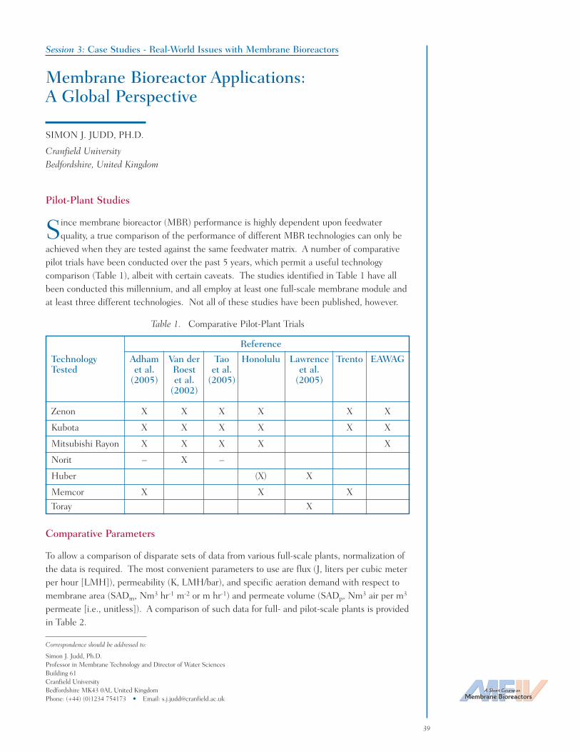
A Short Course on
Membrane Bioreactors
39
Session 3: Case Studies - Real-World Issues with Membrane Bioreactors
Membrane Bioreactor Applications:A Global Perspective
SIMON J. JUDD, PH.D.
Cranfield UniversityBedfordshire, United Kingdom
Pilot-Plant Studies
Since membrane bioreactor (MBR) performance is highly dependent upon feedwaterquality, a true comparison of the performance of different MBR technologies can only be
achieved when they are tested against the same feedwater matrix. A number of comparativepilot trials have been conducted over the past 5 years, which permit a useful technologycomparison (Table 1), albeit with certain caveats. The studies identified in Table 1 have allbeen conducted this millennium, and all employ at least one full-scale membrane module andat least three different technologies. Not all of these studies have been published, however.
Table 1. Comparative Pilot-Plant Trials
Reference
Technology Adham Van der Tao Honolulu Lawrence Trento EAWAGTested et al. Roest et al. et al.
(2005) et al. (2005) (2005)(2002)
Zenon X X X X X X
Kubota X X X X X X
Mitsubishi Rayon X X X X X
Norit – X –
Huber (X) X
Memcor X X X
Toray X
Comparative Parameters
To allow a comparison of disparate sets of data from various full-scale plants, normalization ofthe data is required. The most convenient parameters to use are flux (J, liters per cubic meterper hour [LMH]), permeability (K, LMH/bar), and specific aeration demand with respect tomembrane area (SADm, Nm3 hr-1 m-2 or m hr-1) and permeate volume (SADp, Nm3 air per m3
permeate [i.e., unitless]). A comparison of such data for full- and pilot-scale plants is providedin Table 2.
Correspondence should be addressed to:
Simon J. Judd, Ph.D.Professor in Membrane Technology and Director of Water SciencesBuilding 61Cranfield UniversityBedfordshire MK43 0AL United KingdomPhone: (+44) (0)1234 754173 • Email: [email protected]

Table 2. Summary of Key Parameters
Cap1 Flux K SADm2 SADp
2 MLSS Filt. cycle3 (min) Cleaning Cycle4
(MLD) (LMH) (LMH/bar) (Nm/h) (–) (g/L) on r or b Interval Type
Zenon
p 20 225 0.54 27 10-11p 35 225 0.54 15 10-11p 37.2 270 0.52 14 8-10 9.5 0.5bp 16 120 0.33 22 9 1bp 10 200 0.54 28 7 5 0.5bp 12.4 1245 0.31 25 4-13 12 0.5b2* 18 95 1 56 15 10 0.75b 1w/6m mCIP/R48 18 144 0.29 16 8-10 10.5 1.5r 1w/15m mCIP/R0.15,i 12 71 0.65 54 10-15 10 0.5b 0.5w mCIP48 25 175 0.4 17 12 7 1 0.5m mCIA
Mitsubishi Rayon
p 7.5 200 0.33 52 9-12 1200 240rp 4.8 90 0.37 38 8 8 0.5b/1.5r0.38 10 30 0.65 65 12p 23 140 1 45 8-14 12 2rp 20 665 0.48 20 6-14 13 2r
USF Memcor
p 21.7 150 0.39 18 6-8p 21 182 0.2 170.61 16 1505 0.18 11
Asahi-kasei
0.9,i 16 80 0.24 15 Ind
Koch Puron
0.63 25 160 0.25 10 Mun 5 3w mCIP
Kubota
p 10.4 650 0.75 75 10-12 8 2rp 25 250 0.6 24 9-12 9 1rp 15 261 0.98 79 9 1rp 9.5 200 1.5 88 8 8 2rp 26 6504 0.94 39 6-12 9 1r1.9 20 350 0.75 32 12-18 1380 60r 8-9m CIP13 33 330 1.06 32 8-12 1380 60r 6m CIP4.3 25 680 0.56 23 10-20 1-2 6m CIP
Brightwater
1.2 27 150 1.28 47 12-15 55 5r >18m CIP
Toray
0.53 25 208 0.54 22 6
Huber
0.11 24 250 0.35 22 Mun 9 1 none
Colloide
0.29 25 62.5 0.5 20 Mun 6 2 na
1 Plant capacity or plant type (p = pilot plant); MLD = Megaliters per day.2 Specific aeration demand; Nm/h = Cubic namometers per hour air per cubic meters membrane.3 Filtration cycle (r = relaxation; b = backflush); on = Filtration period.4 Cleaning intervals (w = weeks; m = months).5 Maximum permeability.Intermittent aeration used for all Zenon plants other than *.CIP = Cleaning in place. mCIP = Maintenance cleaning in place.mCIP/R = Maintenance cleaning in place with relaxation. mCIA = Maintenance cleaning in air.
40

It has generally been observed from lab-scale studies that attainable flux increases with increasingaeration rates due to increased scouring. This is manifested either as an increase in thecritical or sustainable flux. In a full-scale plant, this would be expected to be manifested as anincrease in sustainable net permeability with an increasing aeration rate. This, indeed, appearsto be the case, with a general tendency for increasing permeability with increasing SADm,though the data is highly scattered (Figure 1). Some of this data scatter can be attributed toobvious outliers, namely either a plant operating under sub-optimal conditions and/or a verysmall unstaffed plant, where blowers are more likely to be oversized to maintain permeabilityand, therefore, limit maintenance. Sustainable permeability also changes according toclearning protocols and the nature of aeration (i.e., the specifications of the aerator itself andthe mode of application [continuous or intermittent]). Although physical cleaning is, to someextent, accounted for by using net rather than gross flux in calculating permeability,maintenance cleaning with hypochlorite permits higher permeabilities to be sustained.
If the more obvious outliers are ignored, then some general trends can be identified fromthe data:
a) Flat sheet (FS) systems tend to operate at high permeabilities (generally >200 LMH/bar)and are associated with high aeration demands, both as SADm and SADp. No trendis evident in this data subset, though all but the highest (and probably non-optimal)SADp values lie within the range 20 to 39.
b) Hollow fiber (HF) systems tend to operate at lower permeabilities (generally<200 LMH/bar) and are associated with lower aeration demands, sometimesachieved by employing aeration intermittently. For these systems, the permeabilityattained is roughly linearly related to aeration demand (see Figure 1), and SADp
values are generally between 15 and 27.
A Short Course on
Membrane Bioreactors
41
✦ Zenon■ Kubota▲ M Rayon❖ USF✶ Huber● Colloide✣ Asahi-k♦ Puron✧ Brightwater❊ Toray
♦✦
✦✦
✦
✦✦❊
✦
✦
✦
■■■
■
■
■
■■
▲
▲▲▲
▲❖
❖
❖
✶
●✣
✧
800
700
600
500
400
300
200
100
00 0.2 0.4 0.6 0.8 1 1.2 1.4 1.6
SADm, NM^3/hr per m^2
Figure 1. Operating permeability versus specific aeration demand for data in Table 2.
Physical cleaning appears to be predominantly by relaxation rather than by backflushing.Pilot−plant data indicate that the downtime for physical cleaning accounts for between 4 and20 percent of the operating time, with no profound difference between the two configurations.On the other hand, maintenance cleaning every 3 to 4 days using relatively low concentrationsof hypochlorite (250 to 500 milligrams per liter [mg/L]) is routinely employed for the Zenontechnology, whereas chemical cleaning is limited to infrequent recovery cleans alone forFS systems. For both FS and HF systems, such cleans are generally applied at intervals of6 to 18 months (depending on the flux) and generally employ hypochlorite concentrationsbetween 1,000 and 5,000 mg/L sodium hypochlorite (NaOCl). Both maintenance andrecovery cleaning are either brief or infrequent enough to add little to the percentagedowntime. For example, an overnight soak of 16 hours every 6 months amounts to less than0.25 percent in such cases. For Zenon plants, the maintenance cleaning cycle is completewithin 10 minutes and is employed no more than three times a week, again amounting to lessthan 0.4-percent downtime. Thus, for the majority of the most recent plants, the ratio of thenet-to gross flux is determined by a period of relaxation alone, and the most onerous impact ofchemical cleaning is chemical usage and chemical waste discharge.
42
PROFESSOR SIMON JUDD is the Director of Water Sciences at CranfieldUniversity. He has been on the staff at the School of Water Sciences since August1992, and occupies the Chair in Membrane Technology. Judd has managed almostall biomass separation membrane bioreactor (MBR) programs conducted within theSchool and has been Principal or Co-Investigator on three major UK researchcouncil-sponsored programs dedicated to MBRs with respect to in-building waterrecycling, sewage treatment, and contaminated groundwater/landfill leachate. Healso serves as Chairman of the Project Steering Committee of the multi-centeredEU-sponsored EUROMBRA project. In addition to publishing extensively in the research literature,Judd has co-authored two textbooks in membrane and MBR technology, with a third one due out in July2006. Judd received a B.Sc. in Chemistry from the University of Bath, M.Sc. in ElectrochemicalScience from Southampton University, and a Ph.D. in Filtration Science from Cranfield University.

A Short Course on
Membrane Bioreactors
43
Correspondence should be addressed to:
Michael J. Semmens, Ph.D., P.E.Professor, Department of Civil EngineeringUniversity of Minnesota500 Pillsbury Drive SEMinneapolis, MN 55455 USAPhone: (612) 625-9857 • Email: [email protected]
Session 4: Innovative Applications and Future Outlook of the Technology
Membrane Aeration, Biofilms, and Membrane Bioreactors
MICHAEL J. SEMMENS, PH.D., P.E.
University of MinnesotaMinneapolis, Minnesota
The theory of membrane gas transfer has been studied and characterized in detail over thepast 30 years. It is possible to accurately predict the gas transfer performance of
membranes using numerous dimensionless correlations if the membrane area and operatingconditions are known. Membranes are now widely used for gas transfer in a variety ofapplications, including blood oxygenation, vacuum degassing, and pervaporation.Environmental applications of membrane gas transfer have been slower to develop because ofproblems with biofilm fouling of the membrane surface. If we are to design effectivemembrane gas transfer processes for water/wastewater treatment, we need to understand howthese biofilms impact gas transfer. How do these biofilms behave? Is biofilm formationalways a bad thing or are there advantages? This presentation will examine the influence ofbiofilms on the gas transfer performance of membranes and explore opportunities for novelapplications in membrane bioreactors.
PROFESSOR MICHAEL J. SEMMENS, P.E., is Professor in the Department ofCivil and Mineral Engineering at the University of Minnesota, where he has taughtsince 1977. His research interests include the development of physical and chemicalprocesses for water, wastewater, and waste treatment; processes to identify factorsthat limit mass transfer and the kinetics of separation; membrane bioreactors, moduledesign, and membrane applications in water and wastewater treatment; and the useof membranes for controlled gas delivery in biologically active environments, such asgroundwater and sediment remediation projects, and wastewater treatment.Semmens received a B.S. in Chemical Engineering from the Imperial College of Science and Technologyin London, England, an M.S. in Environmental Engineering from Harvard University, and Ph.D. inEnvironmental Engineering from University College in London, England.

44

A Short Course on
Membrane Bioreactors
45
Correspondence should be addressed to:
Simon J. Judd, Ph.D.Professor in Membrane Technology and Director of Water SciencesBuilding 61Cranfield UniversityBedfordshire MK43 0AL United KingdomPhone: (+44) (0)1234 754173 • Email: [email protected]
Session 4: Innovative Applications and Future Outlook of the Technology
Future Outlook on Membrane Bioreactor Technology
SIMON J. JUDD, PH.D.
Cranfield UniversityBedfordshire, United Kingdom
Challenges
Two areas having a direct bearing on the effective and efficient operation of membranebioreactors (MBRs) are 1) cleaning and 2) dynamic effects. The cleaning of surfaces, as
a subject for scientific investigation, pre-dates membrane process development since thefouling of heat exchangers, and the consequent loss of thermal efficiency has been an issue formany years. The fouling and cleaning of membranes relating to industrial process separationshave also been the subject of research and development for over 20 years. Compared to this,the science of membrane cleaning in the context of MBRs is a young one — there have been agreat number of investigations of MBR fouling, but much less on the appropriate chemicalsand protocol for recovering permeability for irreversibly fouled membranes. Given the largenumber of parameters that determine the degree of permanent fouling and the candidatevariable parameters that could determine cleaning efficacy, the scope of a rigorous study ofcleaning is potentially extremely broad. Thus, it is not surprising that cleaning protocols havebeen developed in an ad hoc way through heuristic investigation.
Dynamic effects exert the greatest influence on consistency in MBR performance, ultimatelyleading to equipment and/or consent failures, but have also been largely overlooked by theacademic research community. Specifications for full-scale MBR installations are generallybased on conservative estimates of hydraulic and organic (and or ammoniacal) loading.However, in reality, these parameters fluctuate significantly. Moreover, even more significantand potentially catastrophic deterioration in performance can arise through equipmentmalfunction and operator error. Such events can be expected to produce over short periods oftime (Table 1):
• Decreases in mixed liquor suspended solids (MLSS) concentration (either throughthe loss of solids by foaming or by dilution with feedwater).
• Foaming problems, usually associated with the above.
• Loss of aeration (through control equipment malfunction or aerator port clogging).
• Loss of permeability (through the misapplication of backflush and cleaningprotocols, hydraulic shocks, or contamination of the feed with some unexpectedcomponent).

Table 1. Key Dynamic Determinants and Their Impacts
Determinants Variables
MLSS dilution Dilution factor and rate of concentration increase
Aeration loss Percentage and period of reduction
Backflush/cleaning loss Period of loss
Hydraulic shock Rate and level of flow increase
Saline intrusion Ultimate concentration factor and rate ofconcentration decrease
An example of feedwater constituent fluctuation is seawater intrusion. It has been recognizedfor some time that rapid changes in salinity can impact microbial physiology, increasing levelsof organic matter (as chemical oxygen demand [COD] or biochemical oxygen demand [BOD])arising in activated sludge process (ASP) effluent and decreasing microbial activity. However,the phenomenon has not been investigated for MBRs, where such physiological changes mightbe expected to impact fouling. Further examples include fats, oils, and grease (FOGs) andbacteriological inhibitory substances, since the latter can then alter the system microbiologyand, therefore, generate fouling.
Outlook
Despite the limitation imposed by fouling, the future of membrane bioreactors in municipaland industrial wastewater treatment seems assured. Valued at an estimated $216.6 million in2005, the global MBR market is rising at an average annual growth rate of 10.9 percent,significantly faster than the larger market for advanced wastewater treatment equipment andmore rapidly than the markets for other types of membrane systems. It is expected toapproach $363 million in 2010 (Hanft, 2006). The number of installations for both of theleading suppliers has undergone exponential growth since the first pilot trials of the submergedprocess in 1989 (Figure 1), driven by opportunities presented by increasingly stringentenvironmental legislation and by ever-decreasing process costs (Figure 2). Furtherincremental improvements can be expected as more is understood about the interrelationshipbetween biomass characteristics, permanent fouling, and cleaning, and as membrane costscontinue to be driven downwards. More significant “quantum leap” improvements are lesseasily envisioned, however, and it remains to be seen whether any profoundly original MBRproducts will arise from current research and development activity.
References
Hanft, S. (2006). Membrane Bioreactors in the Changing World Water Market. Business CommunicationsCompany, Report C-240.
Kennedy, S., and C. Churchouse (2005). Progress in Membrane Bioreactors: New Advances, Experiences, andApplications of Membrane Bioreactors in the Treatment of Domestic and Industrial Wastewaters. Wakefield,United Kingdom.
46

A Short Course on
Membrane Bioreactors
47
2004200320022001200019991998199719961995
1500000
1250000
1000000
750000
500000
250000
0
Kubota Zenon
160
140
120
100
80
60
40
20
01992 1994 1995 1996 1998 2000 2002 2004 2005
Year
Rela
tive
cost
/ m
3 at
100
l/s
Rent and ratesSludge disposalScreeningsMembrane replacementChemicalsMaintenancePowerAmortised capital
@ 8640 m3/d
Costs Projected in1999
Actual Costs
Figure 1. Cumulative installed capacity in cubic meters per day (m3/d) for Kubota and Zenon.
Figure 2. MBR process costs (Kubota) versus time (Kennedy and Churchouse, 2005).

48
PROFESSOR SIMON JUDD is the Director of Water Sciences at CranfieldUniversity. He has been on the staff at the School of Water Sciences since August1992, and occupies the Chair in Membrane Technology. Judd has managed almostall biomass separation membrane bioreactor (MBR) programs conducted within theSchool and has been Principal or Co-Investigator on three major UK researchcouncil-sponsored programs dedicated to MBRs with respect to in-building waterrecycling, sewage treatment, and contaminated groundwater/landfill leachate. Healso serves as Chairman of the Project Steering Committee of the multi-centeredEU-sponsored EUROMBRA project. In addition to publishing extensively in the research literature,Judd has co-authored two textbooks in membrane and MBR technology, with a third one due out in July2006. Judd received a B.Sc. in Chemistry from the University of Bath, M.Sc. in ElectrochemicalScience from Southampton University, and a Ph.D. in Filtration Science from Cranfield University.