nvh refinement of diesel passenger vehicles
TRANSCRIPT
1
NVH Refinement of Diesel Passenger Vehicles
ABSTRACT
Modern vehicle development requires NVH refinement to obtain the proper level of customer satisfaction and acceptance. This document outlines the vehicle NVH development process, citing specific examples from a process for a diesel engine application that was derived from a gasoline engine application. The development process utilized in this study starts with an early prototype diesel vehicle, which is analyzed through the application of the Vehicle Interior Noise Simulation (VINS). Structureborne and airborne noise shares are analyzed as a part of the process in the time-domain under both steady-state and transient test conditions. The outcome of the analysis directs product development that addresses the refinement of structureborne and airborne noise. Individual studies are cited to highlight the refinement process for diesel knocking under idle as well as transient test conditions.
In this particular application, the VINS process is utilized to comprehend the impact high frequency dynamic stiffness hydro-mounts have on diesel clatter noise. Examples are also given from studies designed to diminish the perception a vehicle’s powertrain harshness has under on-road operating conditions.
INTRODUCTION
It is common for a customer’s perception of vehicle quality to correspond to the NVH characteristics of the vehicle. Globalization combined with increased marketplace competition in the marketplace requires a vehicle’s NVH characteristics to be well optimized [1]. The sound present in the interior of a vehicle is primarily composed of shares from road noise, wind noise, and powertrain noise. Given the increased market demand for lighter and more powerful vehicles, it becomes evident that powertrain-induced noise is a key component of the vehicle’s interior noise.
Automotive OEMs are increasing the number of powertrains available on vehicle programs because of customer demands. The combination of the being "fun to drive" with the potential for increased fuel economy have made diesel powered vehicles an extremely popular alternative in the global automotive market. However, diesel vehicles, present a unique set of NVH challenges that require solution during the vehicle development process. The adaptation of gasoline powered vehicles for diesel applications further complicates the NVH challenges that are present.
Diesel engines emit higher radiated noise levels than gasoline engines of the same size. Noise emitted from the diesel’s injection system and combustion process results in generally inferior sound quality compared to gasoline engines. Higher engine mount vibration levels and crankshaft torsionals are more prevalent in modern diesel engines than gasoline engines, because of the diesel engine’s high cylinder peak pressures and pressure rise rates. As a result, when diesel engines are integrated into passenger vehicles designed primarily for gasoline engine applications, significant NVH optimization is required to make the diesel vehicles competitive. Limitations placed on the expense and the added requirements for common vehicle parts/architecture (across various powertrains) require that state-of-the-art techniques be used to identify unique diesel specific strategies that are cost effective and provide the most desired NVH benefits.
Specifically, this document illustrates the use of a VINS technique to assist in the diesel NVH vehicle development process. This study applies examples of the VINS process to the optimization of a passenger car equipped with a transversely-mounted 4-cylinder turbocharged diesel engine mated to a manual transmission. The VINS process is used in this study for the refinement of powertrain harshness and diesel clatter noise. The mounting configuration of the powertrain in the test vehicle is illustrated in Figure 1.

2
Figure 1: Powertrain Installation in Vehicle
VEHICLE INTERIOR NOISE SIMULATION (VINS)
VINS is a time-domain transfer path synthesis technique that allows for an accurate breakdown of the powertrain induced interior sound at a target location in a vehicle. While the details of this technique can be found in previous publications [2,3], a brief overview of the VINS process is provided here.
As show schematically in Figure 2, the VINS process begins by measurements of the airborne and structureborne sources. Accordingly, radiated powertrain noise, intake orifice noise, and exhaust tailpipe noise measurements are used to characterize the sources of vehicle interior airborne noise contributions. Similarly, mount vibration measurements (engine side) are used to quantify the source levels of structureborne inputs into the vehicle. The source measurements are used in conjunction with corresponding vehicle level transfer functions (airborne and structureborne) to simulate the powertrain-induced interior noise shares from the various airborne and structureborne paths.
The primary advantage of the time-domain simulation over comparable frequency-domain techniques is that the resulting path contributions can be evaluated both objectively and subjectively via listening studies. In addition to the typical steady-state or quasi-steady-state results, the VINS analysis can be applied to transient test conditions. Hence, items such as diesel clatter under transient pedal tip-in conditions, as well as modulation noise (typically subjectively objectionable despite reasonable overall sound levels) can be readily understood using the VINS process.
Figure 2: VINS Methodology
One additional advantage of the VINS analysis which is relevant in this case study is the prediction of the engine mounts’ dynamic stiffness properties. The structural paths are treated as shown in Figure 3, with the dynamic stiffness properties of the mount calculated based on the operating transmissibility of the mount and on the point mobility of the body attachment location. As discussed by Lee et. al., prediction or measurement of dynamic mount stiffness becomes challenging even at relatively low frequencies such as 600 Hz [4]. This treatment of the dynamic stiffness of the mount allows for a true in-situ evaluation of the dynamic stiffness characteristics of the mount and hence provides accurate estimation of mount stiffness properties beyond the practical frequency range limitations of a mount test bench measurement. In addition, the VINS process captures the dynamic stiffness of the mount under the right preload, deflection amplitude, and temperature boundary conditions, based on the test condition being investigated.

3
Figure 3: VINS Mount Stiffness Prediction
DIESEL VEHICLE NVH VINS APPLICATIONS
This section provides examples of the VINS process, as applied towards vehicle NVH refinement of a diesel passenger sedan. The VINS process was integrated into the normal vehicle development process. As indicated previously, the examples are from the development of a passenger car powered by a transversely mounted 4-cylinder turbocharged diesel engine mated to a manual transmission.
Initial subjective and objective tests conducted on early prototype vehicles indicated that the most critical areas that needed NVH refinement were the areas of powertrain harshness (under engine load) and diesel clatter under idle and transient conditions (under light load). Hence, the VINS process was applied specifically to the following two conditions.
• Powertrain harshness under full load conditions • Diesel clatter under idle and part load conditions
The details of the tests, VINS analyses, and countermeasure development are discussed in the following sections.
POWERTRAIN HARSHNESS REFINEMENT
As noted previously, one of the areas of NVH refinement was deemed to be powertrain harshness under high engine load conditions. Hence, the VINS process was initially focused to fully understand the powertrain-induced interior noise under these conditions. Tests involved a combination of vehicle sensitivity measurements to identify all relevant airborne and structureborne transfer functions, as well as operating measurements under full engine load conditions, conducted in a semi-anechoic chassis roll dynamometer test cell. As an example, Figure 4 shows a photograph of the setup used to conduct airborne transfer path sensitivity measurements. In this setup, a dodecahedral speaker was used as the acoustic source (placed in the passenger compartment) and the acoustic transfer functions (engine compartment, intake snorkel, exhaust tailpipe) were measured reciprocally.

4
Figure 4: Airborne Transfer Function Measurements
The airborne and structureborne transfer functions were combined with operating measurements to conduct a VINS analysis of the vehicle under full engine load conditions. Operating measurements consisted of interior sound measurements, acoustic “source” measurements (microphones in the engine compartment, at intake snorkel, and exhaust tailpipe) as well as triaxial acceleration measurements (“active” and “passive” sides of powertrain mounts). Figure 5 shows a comparison of measured interior sound data and that simulated by the VINS process.
Figure 5: Comparison of Measurement and VINS
The comparison in Figure 5 shows good correlation between the measured interior sound and that synthesized by the VINS simulation. Listening studies were conducted to further confirm the correlation between measured and simulated interior sound data.
The harsh character of the sound was driven by two attributes; resonances in the overall level caused by structureborne noise in the lower frequencies and high-frequency airborne diesel combustion noise. The overall noise level resonances are driven by primary engine firing content, particularly the 2nd and 4th orders.
To diagnose these issues further, the developed VINS model was decomposed into various component noise shares. As shown below in Figure 6, the analysis indicates that a main area of concern for the low frequency behavior is the front roll restrictor. Although the primary area of concern was high levels of body transfer sensitivity, the ability to fully address

5
this issue was limited by the rather narrow powertrain variant scope of this project. As a result of the findings, a tuned mass absorber on the isolated front sub-frame and the roll restrictor properties were modified, with the results summarized in Figure 7. Specifically, the roll restrictors were tuned by decreasing the front roll restrictor’s stiffness and making a comparable increase in the rear roll restrictor to maintain powertrain roll control but direct more force to the less sensitive rear roll restrictor path. A dynamic mass absorber on the isolated front sub-frame was modified to a solid mass absorber, which was consistent with the gasoline I4 application and was observed to reduce vehicle sensitivity in the 130-240 Hz frequency range.
Figure 6: 130-240 Hz Primary Noise Shares
Figure 7: Influence of Front Roll Restrictor Tuning
For the high frequency diesel clatter noise from approximately 1000 to 3000 Hz, the engine radiated sound paths were found to be dominant. Although the airborne transfer sensitivity was observed to be near typical ranges, the ability to refine calibration of the engine for reduced source levels was limited by the other calibration requirements of good fuel economy and emissions performance. As a result, the borderline airborne transfer sensitivity was further investigated for sound package improvement opportunities. Several areas of marginal improvement were identified to improve the airborne transfer sensitivity, including the following.
• Addition of a fender acoustic barrier • Improved steering column boot • Improved windshield sealing • Additional acoustic absorption material in engine compartment and center console areas
The overall resulting improvements are shown in Figure 8, where the Articulation Index provides an overall indication of mid- to high- frequency sound reductions.
noise problemcriticalOK

6
Figure 8: Influence of Sound Package Improvements
DIESEL CLATTER NOISE REFINEMENT
Upon development of countermeasures to achieve the desired level of powertrain harshness improvement, attention was focused on improving the diesel clatter noise characteristics of the vehicle, prevalent under idle and light load transient tip-in conditions. The airborne and structureborne transfer function measurements from the earlier VINS analysis on powertrain harshness were leveraged in the development of a VINS model to address the diesel clatter noise refinement. Source measurements were conducted under idle and transient conditions and used in conjunction with the measured transfer functions to construct a new VINS model.
As shown in Figure 9, the objectionable characteristic was a strong 2nd order modulation of sound in the 600-700 Hz band, which was absent from a competitive vehicle. Since the modulation was created by the engine, and system and emissions constraints prevented significant changes to the engine excitation, the primary focus was on reducing the excitation of the resonance content between 600 Hz and 700 Hz.
Figure 9: Modulation Spectra of Idle Clatter Noise
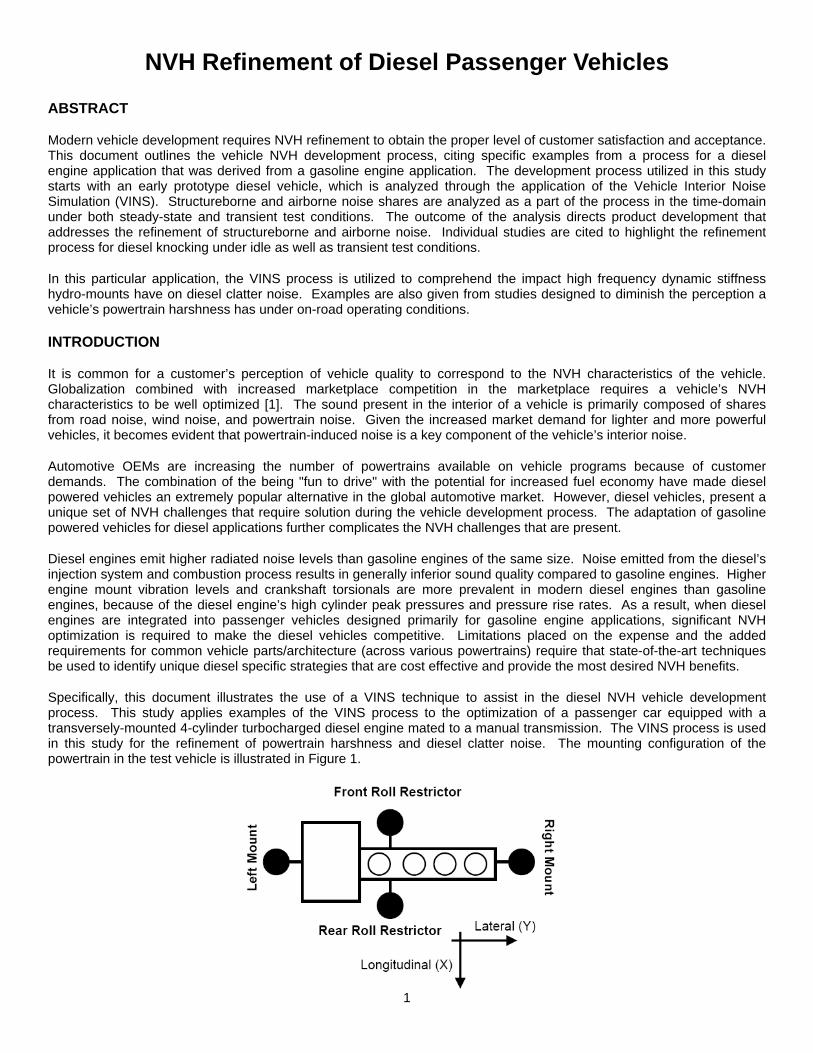
As shown in Figure 10, the primary frequency content of the clatter noise is in the 600-700 Hz band and the objectionable character is not only a relatively high level in the band but also the modulation of the level with time as suggested by the above modulation spectra. Both characteristics are predicted with an idle VINS, although the modulation character can only result from specific engine processes [e.g., 5, 6].
The objectionable frequency content was primarily through the right hand engine mount path. The right mount has a dominant noise share as a result of high excitation and high dynamic stiffness of the mount in the 600-700 Hz frequency range. As with the high load operation, idle and light load engine calibration changes were difficult to contain due to strict
Arti
cula
tion
Inde
x %
7
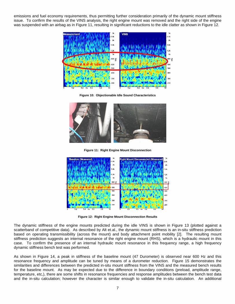
emissions and fuel economy requirements, thus permitting further consideration primarily of the dynamic mount stiffness issue. To confirm the results of the VINS analysis, the right engine mount was removed and the right side of the engine was suspended with an airbag as in Figure 11, resulting in significant reductions to the idle clatter as shown in Figure 12.
Figure 10: Objectionable Idle Sound Characteristics
Figure 11: Right Engine Mount Disconnection
Figure 12: Right Engine Mount Disconnection Results
The dynamic stiffness of the engine mounts predicted during the idle VINS is shown in Figure 13 (plotted against a scatterband of competitive data). As described by Alt et.al., the dynamic mount stiffness is an in-situ stiffness prediction based on operating transmissibility (across the mount) and body attachment point mobility [2]. The resulting mount stiffness prediction suggests an internal resonance of the right engine mount (RHS), which is a hydraulic mount in this case. To confirm the presence of an internal hydraulic mount resonance in this frequency range, a high frequency dynamic stiffness bench test was performed.
As shown in Figure 14, a peak in stiffness of the baseline mount (47 Durometer) is observed near 600 Hz and this resonance frequency and amplitude can be tuned by means of a durometer reduction. Figure 15 demonstrates the similarities and differences between the predicted in-situ mount stiffness from the VINS and the measured bench results for the baseline mount. As may be expected due to the difference in boundary conditions (preload, amplitude range, temperature, etc,), there are some shifts in resonance frequencies and response amplitudes between the bench test data and the in-situ calculation; however the character is similar enough to validate the in-situ calculation. An additional

8
advantage of the VINS mount stiffness prediction is that the prediction extends beyond the typical range of a test bench fixture, which is often limited to maximum frequencies of ~700 Hz.
Figure 13: Idle VINS Dynamic Mount Stiffness Estimates
High Frequency Dynamic Mount Stiffness
0 100 200 300 400 500 600 700Frequency (Hz)
K* (
N/m
m)
Baseline MountReduced Durometer Mount
~600 Hz~400 Hz
Figure 14: Dynamic Mount Stiffness Bench Data
Dynamic Mount Stiffness Comparison
0 100 200 300 400 500 600 700Frequency
dB (N
/m/s
2)
47 Duro, Test Bench47 Duro, VINS Prediction
5 dB
Figure 15: Dynamic Mount Stiffness Comparison
Further investigations continued to explore the combined influence of the right engine mount bracket (known to be compliant in this frequency range) and the mount durometer. Initial studies found that an additional mass on the active side mount bracket (in combination with the reduced durometer mount) further reduced the ~600 Hz resonance content, and that changing bracket materials from aluminum to cast iron could provide similar benefits with lower additional cost. These key results are shown in Figure 16 for idle clatter (plotted against a scatterband of competitive data) and Figure 17 for part-load acceleration clatter.

9
Figure 16: Right Mount Changes (Idle Clatter)
Figure 17: Right Mount Changes (Part Load Clatter)
SUMMARY AND CONCLUSIONS
The extension of a gasoline-based vehicle platform to include the option of a diesel engine variant demands the addition of vehicle-level NVH development. Improvements in the vehicle’s sound package are probable, due to higher levels of airborne and structureborne noise sources from a diesel engine and the requirement to meet low level exhaust emission requirements and increased fuel economy requirements. These improvements can be focused further through the use of appropriate transfer path techniques. The higher loads present in a diesel engine are likely to drive structural NVH refinements to maintain the levels of NVH performance. A detailed focus of these investigations can be provided through a VINS analysis. Specific advantages can be seen through the application of a VINS analysis to predict internal mount resonance phenomena and can be combined with tuned bracket designs to refine structureborne noise in key frequency bands. Optimum and cost-effective NVH refinement can be achieved in the diesel vehicle NVH design process and significant engineering insight can be acquire through the use time-domain based transfer path tools such as VINS.
ACKNOWLEDGEMENTS
We acknowledge the support of DaimlerChrysler’s and FEV’s management for various portions of the work presented in this paper.
In addition, the support of Tom D’Anna, Brian Purdy, Justin Via, and Tom Houle towards accomplishing various portions of this project is acknowledged.
REFERENCES
1. K. Govindswamy, M. Hueser, “Developed on the Quiet”, Engine Technology International, March 2002 Issue, pp. 44-47
2. N. Alt, N. Weihagen, N. Schlitzer, M. W. “Interior Noise Simulation for Improved Vehicle Sound“ SAE 2001-01-1539

10
3. Eisele, G. Wolff, K. Alt, N. Hüser, M. SAE 2005-01-2514, “Application of Vehicle Interior Noise Simulation (VINS) for NVH Analysis of a Passenger Car” May 2005
4. Lee, J. Bae, M. Kim, K. “Limitations of Mechanical Model With Lumped Mass in Representing Dynamic Characteristics of Hydraulic Mount” SAE 2003-01-1466
5. Nehl, J. Wilhelm, M. Gauch, P. Travert, M. “Evaluation of Crankshaft Clearance Influence on Specific Roughness Noise Concern” SAE 1999-01-1771
6. Hoard, J. and Rehagen, L. “Relating Subjective Idle Quality to Engine Combustion” SAE 970035
DEFINITIONS, ACRONYMS, ABBREVIATIONS
ABN: Airborne Noise
EO: Engine Order
FFR: Front Roll Restrictor
RR: Roll Restrictor
RRR: Rear Roll Restrictor
SBN: Structureborne Noise