numerical simulation of mixed brine-co2/h2s-rock ... simulation of mixed brine-co 2 /h 2 ......
TRANSCRIPT

PROCEEDINGS, 41st Workshop on Geothermal Reservoir Engineering
Stanford University, Stanford, California, February 22-24, 2016
SGP-TR-209
1
Numerical Simulation of Mixed Brine-CO2/H2S-Rock Interaction During the Reinjection of
Non-condensable Gases
Alex Grey M. Saldaña1, Eylem Kaya
1*, Sadiq J. Zarrouk
1, Victor Callos
1, Bruce W. Mountain
2
1Department of Engineering Science, University of Auckland, Private Bag 92019, Auckland 1142, New Zealand 2GNS Science, Wairakei Research Centre, New Zealand
Keywords: non-condensable gases, NCG, CO2 sequestration, geochemical reactions, fluid-rock interaction geothermal reservoir
modeling, TOUGHREACT
ABSTRACT
There is an increased interest in the reinjection of non-condensable gases (NCG) from geothermal power stations into geothermal
reservoirs. NCG reinjection can serve as a means of reducing greenhouse gas emissions into the atmosphere, provide reservoir pressure
support and possibly can be considered a stimulation method to improve reservoir permeability. Reservoir modeling studies are essential
in understanding the behavior of injected gases in the reservoir and forecast possible NCG breakthrough to production wells. The NCG
can be injected either as dissolved gas in water or as supercritical fluid. This paper aims to determine how a geothermal reservoir rock
will behave during injection of a representative mixture of CO2/H2S-water injection.
A laboratory scale flow-through experiment was conducted to investigate the complex interaction between CO2/H2S-brine and
greywacke rock sample. By introducing detailed reactive chemistry into the injected liquid mixture and mineral composition, this study
simulates the conditions of the experiment, and attempts to quantify the fluid-rock interactions for a better understanding of the impact
of NCG reinjection on the reservoir porosity and permeability. This is to assess the potential use of long and short term NCG reinjection
in conventional geothermal systems. Reasonable match was obtained between experimental data and geochemical modeling using the
TOUGHREACT simulator. The simulation study showed that all the reactions are taking place very fast at reservoir temperature,
indicating thermodynamically-controlled reactions (equilibrium).
1. INTRODUCTION
Geothermal fluid contains variable quantity of NCG, consisting primarily of CO2, H2S, N2, NH3, H2, and CH4. The total gases can be as
high as 15% by weight of the total fluid extracted. The presence of NCG, in particular CO2 and H2S, in the geothermal fluids often
presents a challenge as these are associated with corrosion, calcite deposition, reduced power plant efficiency, and health, safety, and
environmental risks (Papic, 1991; DiPippo, 2012).
The NCG are accumulated in the geothermal power plant condenser, hence the name is NCG, and have to be extracted. These gases are
conventionally extracted and discharged to the atmosphere using some of the generated power.
CO2 is the dominant NCG, making up to about 90% of the total gases in most geothermal systems (Truesdell, 1979; Mahon, 1980). The
major sources of CO2 may be from magmatic origins, sedimentary formations, organic matter, and shallow bicarbonate springs. CO2 is
also associated with the occurrence of hydrothermal calcite deposition near-wellbore through the following equilibrium reaction
(Satman et al., 1999):
𝐶𝑎2+ + 2𝐻𝐶𝑂3 − ↔ 𝐶𝑎𝐶𝑂3 ↓ (deposition) + 𝐻2𝑂 + 𝐶𝑂2 ↑ (1)
With the exsolution of CO2 from the geothermal fluids such as by boiling in the hot up-flow region of the reservoir or rapid degassing
such as in a vertical geyser vent or a in production well, the forward reaction is favored and calcite deposits (Simmons and Christenson,
1994; Jones and Renaut, 1998).
Hydrogen sulfide, on the other hand, is a flammable, reactive and toxic gas, which can cause possible life-threatening risks. Sulfur
dioxide (SO2) is a known component of acid rain, results as an oxidation product of H2S.
Reinjection of CO2 into geothermal reservoirs is receiving increasing interest from many industries to minimize the emission of the
greenhouse gas into the atmosphere and to extend the productive life of geothermal reservoirs through pressure support. The presence of
CO2 in the reservoir fluid lowers the flash point pressure of the mixed fluid and promotes boiling. This will induce the formation of a
gas phase in the geothermal reservoir, and in the process help maintain higher total reservoir pressures. Injected CO2 could be in the
form of supercritical state or dissolved in water (brine). Injection of CO2 with brine is preferred over single phase CO2 injection since it
enhances geochemical reaction rates and increases reservoir permeability. This method also decreases the risk of gas leakage due to
reduced buoyancy effects and formation damage caused by high injection pressures of supercritical fluid.

Saldaña et al.
2
The mineral alteration induced by injection of CO2 can lead to changes in porosity. Furthermore, co-injecting H2S can cause additional
porosity changes in the acidified zones where mineral dissolution dominates, e.g. the reaction of ferrous iron with dissolved sulfide can
form pyrite:
Fe2+ + 2HS- ↔ FeS2 (pyrite) + 2H+ + 2e (2)
NCG reinjection has been applied to geothermal reservoirs, with a variable success, in few fields including: Hijiori, Japan (Yanagisawa,
2010); Ogachi, Japan (Kaieda et al., 2009); Hellisheidi Iceland, (Alfredsson and Gislason, 2009), Coso, (Nagl, 2010; Sanopoulos and
Karabelas, 1997) and Puna (Richard, 1990). At Hijiori, Ogachi, and Hellisheidi, CO2 was dissolved in water at very low concentrations
(0.01 to 3 % by weight) prior to injection. The Coso Geothermal field has been accepting dissolved NCG in the reinjection water but
later switched to H2S removal system due to reduced reservoir performance (Nagl, 2009). Pilot-scale experiments have also been
conducted in the Hellisheidi and Nesjavellir power plants in Iceland to assess the feasibility of in-situ sequestration of both CO2 and H2S
in basaltic formations (Gunnarsson, 2013; Ingimundarson, 2015). Field CO2 injection experiment was conducted in Ogachi HDR
geothermal site (Kaieda et al., 2009) by injecting neutralized river water and dry ice in a granitic reservoir to study the feasibility of the
reservoir for carbon storage. It is essential to understand the chemical reaction mechanisms taking place as the CO2-enriched fluid
interacts with the reservoir rocks, as these are very important to evaluate the storage capacity of the host rocks: this is to effectively
store, trap, and immobilize the injected CO2 for extended periods of time (Mountain and Higgs, 2015). The properties of both rock and
fluid will be altered upon sufficient contact, and how these properties are altered depends on: the target rock mineralogy, permeability,
fluid composition, temperature, pressure, and duration of contact (Browne, 1978).
A growing number of experiments and numerical simulation studies are being conducted to explore the mechanisms and reactions
prevalent in rock-fluid-CO2 environments. Mountain and Higgs (2015) performed a flow-through laboratory experiment wherein
sandstone is reacted with distilled water and synthetic brine under conditions common to Kupe South oil and gas field, New Zealand. In
their experiments, dissolved CO2 was injected into a sample of sandstone inside a pressure vessel. Similar set-up was also used by
Torres and Aqui (2015) to investigate the interaction between andesite and Wairakei condensates while Sonney and Mountain (2013)
investigated interaction between greywacke and distilled water and Wairakei reinjection brine. Torres and Aqui (2015) observed
dissolution of quartz and feldspar, while secondary minerals anhydrite, chlorite, smectite, and zeolite, and most likely plagioclase
precipitated out of solution at higher temperatures. Dissolution is considered to be the predominant process and caused permeability
enhancement in their rock samples. On the other hand, Sonney and Mountain (2013) reported that, at room temperature, carbonate
containing minerals dissolved through contact with either fluid, and elevated concentrations of Ca, Mg, and Sr were detected
accompanied by an increase in pH. However a rapid decrease in pH was observed after the temperature was increased, indicating initial
precipitation of secondary aluminosilicates, then a steady-state between dissolving primary minerals and precipitating secondary
minerals. Other similar laboratory scale experiments are listed in Table 1.
Table 1. An overview of laboratory scale experiments of CO2-water-rock interactions.
Reference Temperature
(ºC)
Pressure
(MPa)
Length
(days)
Initial Solids Aqueous Fluid Alteration
Bischoff &
Rosenbauer, (1996) 200 and 350 50 84-124
rhyolite
(ryodacite) CO2 - water dissolution of feldspar
Shiraki & Dunn, (2000) 80 16.6 164 hrs Sandstone
CO2 + synthetic reservoir brine
dissolution of dolomite; K-feldspar to kaolinite
Kaszuba et al.,
(2003) 200 20 139 Arkose supercritical CO2 - brine smectite precipitation
Ueda & K., (2005) 200 2-6 15 granodiorite and plagioclase
DI water w/ supercritical CO2
calcite and kaolinite precipitation
Suto et al., (2007) 100-350 250 7 Granite CO2 - water
kaolinite, muscovite,
smectite, calcite precipitation
Credoz et al., (2009) 80 and 150 15 30-365
sandstone and
limestone
supercritical CO2 +
synthetic brine
dissolution of carbonates, kaolinite; destabilization of
illite/smectite
Lin et al., (2008) 100 15 2 Granite supercritical CO2 calcite , aluminosilicate precipitation
Wigand et al., (2008) 60 15 63 Sandstone
supercritical CO2 +
synthetic brine
dissolution of dolomite, K-
feldspar and albite
Fischer et al., (2010) 40 5.5 105
quartz and
plagioclase CO2 + synthetic brine
dissolution of plagiooclase, K-feldspar and anhydrite;
formation of albite
Holubnyak et al., (2011) 80 14.5 28
dolomite (60-75%) 10% wt NaCl dissolution of carbonates
Sonney & Mountain,
(2013) 210 3.5 41 Greywacke re-injection brine formation of clay minerals
Luhmann et al., (2014) 100 15
61 min - 9 days dolomite CO2 + synthetic brine dissolution of dolomite
Torres & Aqui,
(2015) 230 20 42 Andesite
Wairakei, steam
condensate
dissolution of quartz and
feldspar; deposition of
anhydrite chlorite and zeolites

Saldaña et al.
3
Effects of CO2 reinjection is also modelled by using reactive transport modeling. According to Xu and Pruess (2010), for the case of
CO2 injection into a rock mainly composed of altered granite; calcite, K-feldspar and chlorite are dissolved, while dolomite, siderite and
ankerite are precipitated and the mineral alteration resulted in a net decrease in porosity of the reservoir. However, Xu et al. (2010)
showed that co-injection of water with supercritical CO2 resulted in strong porosity enhancement by dissolution of calcite, while
sequential injection of CO2 and water brought about a very small porosity enhancement.
Co-injection of CO2, H2S, and SO2 gases into an arkose formation was also investigated by Xu et al. (2007). CO2 sequestration occurred
by precipitation of secondary carbonates calcite, ankerite, and dawsonite, with most of the deposits forming beyond the acidified zone
(100 m away from the wellbore). Co-injection of H2S brought about precipitation of pyrite while SO2 co-injection resulted in
precipitation of pyrite, anhydrite, and alunite; both occurring within the acidified zone. Significant changes in porosity occurred within
this acidified zone, where mineral dissolution dominates.
Beni et al. (2012) simulated the reaction of Bunter sandstone formation, which is mainly composed of quartz, K-feldspar, mica, chlorite
and kaolinite with brine and CO2. Water-rock interaction resulted into the alteration of aluminum silicates and precipitation of
secondary carbonates (dawsonite, ankerite, and siderite). Porosity was also significantly decreased to 9% of the initial value. Effects of
CO2 gas injection in an enhanced geothermal system (EGS) in the Songliao Basin, China was studied by Na et al. (2015). Laboratory
experiments and numerical modeling using the TOUGHREACT code (Xu et al., 2011) were conducted under reservoir conditions (160 oC and 35MPa) for 12 days. Numerical simulations were partly successful in reproducing experimental results and show an increase in
HCO3- , Ca+2, K+, Fe+2, and SiO2 (aq) concentration, coupled with a decline in pH, consistent with dissolution of primary minerals.
Precipitation of secondary carbonates calcite and ankerite was also observed.
Shevalier et al. (2011) and Dalkhaa et al. (2013) set up a 1-D and 2-D model for CO2 injection in a saline aquifer that contains H2S
using TOUGHREACT. Nisku carbonate formation which is mainly composed of dolomite (>80%) and calcite (16%) was reacted with
brine containing CO2 and H2S. The presence of dissolved H2S did not have significant effect on water-rock interaction. Significant
dissolution of dolomite resulted in the increase in porosity by ~0.2%.
In this paper a reactive transport model was created to simulate a laboratory scale experiment (Passarella et al., 2015) of geothermal
brine containing high concentration of dissolved CO2 and H2S and rock interaction. The rock sample is greywacke, which is a
representative lithology of some of the reinjection aquifers in the Taupo Volcanic Zone (TVZ). The laboratory experiment focuses on
interactions between unaltered (fresh) greywacke and fluid under geothermal reservoir pressure and temperature conditions. The aim of
this study is to recreate experimental analogues of the geochemical processes occurring during re-injection. This thermochemical flow
modelling will be used to assess the reaction rates and investigate their effects on porosity and permeability of the rock sample.
TOUGHREACT simulator was used, with the fluid property modules ECO2N and EOS1, to account for the effects of chemically
reactive fluids in porous and fractured media in non-isothermal flows. PyTough (Wellmann et al., 2012) software was used for model
set up and data processing.
2. MODELING OF LABORATORY SCALE NCG-WATER-ROCK INTERACTION EXPERIMENT
2.1 EXPERIMENTAL DESIGN
The model was based on the results of the flow-through experiment conducted by Passarella et al. (2015). This experiment was designed
following the set-up of Mountain and Higgs (2015), Torres and Aqui (2015) and Sonney and Mountain (2013) (see Figure 1). A rock
sample from the Waotu quarry southeast of Hamilton, New Zealand was used in the experiment. This is similar to greywacke that
comprises the basement rock in which re-injection of brines is occurring in some of the geothermal systems in the TVZ. It consists of
clasts of siltstone, basalt, quartz, plagioclase, pyroxene and hornblende in a matrix of quartz, feldspar, chlorite, illite, calcite and pyrite.
The fluid to which it comes into contact is a mixture of low pressure separator brine from a New Zealand geothermal power station. A
synthetic NCG mixture containing CO2/H2S/H2 in the ratio of 96%/4%/0.1% is added to this brine.
The experiment was carried out following these steps:
1. The rock sample is coarsely-crushed in a roller mill, sieved to obtain the 355 – 500 µm mesh size, and cleaned several times in an
ultrasonic bath in distilled water to remove fine particles. The mineral composition of the unreacted rock was not measured, thus it was
assumed based on the modal composition of basement greywacke drill cuttings at Ohaaki (Wood et al., 2001) and XRD analysis of
“fresh” greywacke used by Sonney and Mountain (2013). The clean sample is put in a titanium pressure vessel and placed inside an
insulated oven. The unreacted rock was analyzed with X-ray diffraction spectrometer (XRD) and scanning electron microscopy (SEM)
for comparison with the reacted grains collected after the experiment.
2. 800 mL of de-oxygenated brine from Wairakei power station was drawn into the accumulator and compressed with 200 mL synthetic
gas mixture containing CO2/H2S/H2 (96%/4%/0.01%) at 35 bar. At first, complete mixture of the brine and NCG mixture was not
attained, and the accumulator had to be inverted to allow complete homogenization of the fluid mixture. The brine-NCG mixture was
not analysed for its chemistry due to the high pressure (laboratory analysis normally done at atmospheric pressure, will yield different
values due to exsolution of gas).
3. Gas enriched fluid was pumped at 1.0 ml hr-1 into the pressure vessel at room temperature for 6 days.
Saldaña et al.
4
4. The temperature was then increased to 200 oC and maintained for another 60 days. Flow rate was reduced to 0.5 ml hr-1 at 38 days
into the experiment, in order to test for equilibrium conditions. The temperature is monitored by a thermocouple inserted at the top of
the pressure vessel. The fluid pressure is maintained by a back pressure regulator.
5. During injection, water and gas samples are collected daily and analysed in bulk after the experiment. The effluent was analysed for
Li, Na, K, Mg, Ca, Sr, Mn, Fe, As, Al, B, SiO2, Cl-, and SO4-. CO2 was analysed by back titration and H2S by methylene blue reaction.
XRD and SEM were used to characterize mineral and chemical composition of the reacted rock samples and compared with the
unreacted samples.
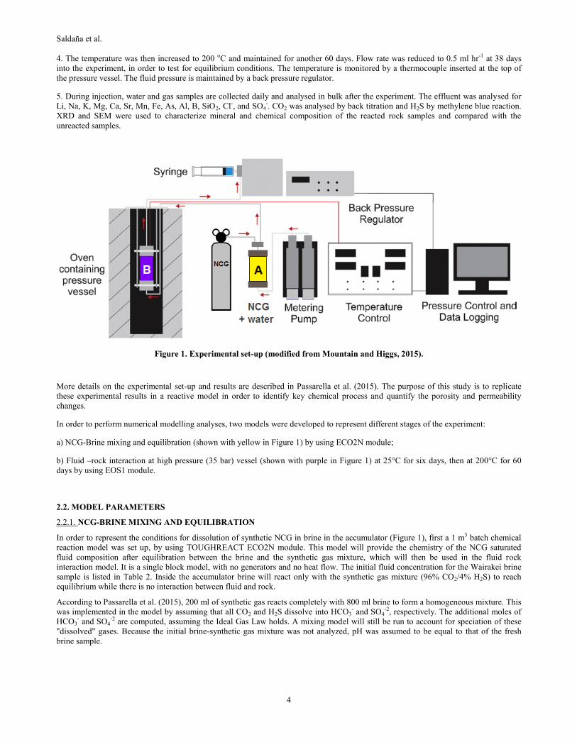
Figure 1. Experimental set-up (modified from Mountain and Higgs, 2015).
More details on the experimental set-up and results are described in Passarella et al. (2015). The purpose of this study is to replicate
these experimental results in a reactive model in order to identify key chemical process and quantify the porosity and permeability
changes.
In order to perform numerical modelling analyses, two models were developed to represent different stages of the experiment:
a) NCG-Brine mixing and equilibration (shown with yellow in Figure 1) by using ECO2N module;
b) Fluid –rock interaction at high pressure (35 bar) vessel (shown with purple in Figure 1) at 25°C for six days, then at 200°C for 60
days by using EOS1 module.
2.2. MODEL PARAMETERS
2.2.1. NCG-BRINE MIXING AND EQUILIBRATION
In order to represent the conditions for dissolution of synthetic NCG in brine in the accumulator (Figure 1), first a 1 m3 batch chemical
reaction model was set up, by using TOUGHREACT ECO2N module. This model will provide the chemistry of the NCG saturated
fluid composition after equilibration between the brine and the synthetic gas mixture, which will then be used in the fluid rock
interaction model. It is a single block model, with no generators and no heat flow. The initial fluid concentration for the Wairakei brine
sample is listed in Table 2. Inside the accumulator brine will react only with the synthetic gas mixture (96% CO2/4% H2S) to reach
equilibrium while there is no interaction between fluid and rock.
According to Passarella et al. (2015), 200 ml of synthetic gas reacts completely with 800 ml brine to form a homogeneous mixture. This
was implemented in the model by assuming that all CO2 and H2S dissolve into HCO3- and SO4
-2, respectively. The additional moles of
HCO3- and SO4
-2 are computed, assuming the Ideal Gas Law holds. A mixing model will still be run to account for speciation of these
"dissolved" gases. Because the initial brine-synthetic gas mixture was not analyzed, pH was assumed to be equal to that of the fresh
brine sample.

Saldaña et al.
5
Table 2. Initial fluid composition for Wairakei brine sample and results of mixing model
Chemical
Parameter
Initial brine composition Equilibrated totally dissolved
gas
(mg kg-1
) (mol kg-1
H2O)
(mol kg-1
H2O) pH 5.0 5.0
Na+ 736.54 3.22E-02 3.20E-02
K+ 213.83 5.50E-03 5.47E-03
Ca+2 3.61 9.06E-05 9.01E-05
Mg+2 0.05 1.96E-06 1.95E-06
Fe+2 0.86 1.54E-05 1.53E-05
AlO2- 0.9 3.36E-05 3.34E-05
Cl- 1747 4.94E-02 4.91E-02
HCO3- <20 3.29E-04 3.39E-01
SO4-2 96 1.00E-03 9.98E-04
SiO2 (aq) 1121.44 1.88E-02 1.87E-02
As 3.23 4.33E-05 4.30E-05
B(aq) 36.59 3.40E-03 3.38E-03
Li+ 9.5 1.38E-03 1.38E-03
Mn+ 0.04 7.82E-07 7.78E-07
CO2(aq) NA NA 3.20E-01
H2S(aq) NA NA NA
2.2.2. FLUID –ROCK INTERACTION MODEL
A NCG-brine–rock interaction model was set up in order to represent the chemical reactive behavior of the sample at high pressure (35
bar) vessel (shown with purple colour in Figure 1).
Geometry : The model is based on the dimensions of the experimental set-up, and is radial, of 150mm length and radius of 6.25mm
(Figure 2). This is discretized into 10 radial grid blocks and 22 layers.
Figure 2. Flow model grid structure. Radial axis is scaled with respect to the vertical axis. Red blocks represent sources.
Initial and boundary conditions: Generation blocks, representing the injection of experimental fluid below the pressure vessel, are
assigned to the seven blocks closest to the center at the bottom-most layer (blocks colored in red in Figure 2). A large volume topmost
block was considered in order to maintain constant pressure (35 bar) and temperature (25°C and 200°C) conditions.
Initial geochemical conditions: The initial mineral composition of a representative sample of greywacke formation used in the
modelling is shown in Table 3. Table 4 lists the parameters assigned to each of the grid blocks assuming the composition of the rock is
uniform. The porosity and permeability were estimated from experience, but for the changes in the permeability due to reaction, a
simplified form of the Kozeny-Carman equation was used (Xu et al., 2011). The parameters used to determine the kinetic rate constants
Saldaña et al.
6
of the minerals are given by Palandri and Khalaka (2004) and in the study by Xu et al (2011). Smectite, pyrite, and magnetite, observed
in the reacted grains during the laboratory experiment, were included in the model as secondary minerals. Kaolinite, illite, magnesite,
dolomite, dawsonite, ankerite, siderite, albite, anhydrite were also considered, as these are likely to be precipitated in very small
amounts, and thus, may not have been observed during petrographic analysis of the reacted rock samples.
The results obtained from the mixing model were used for the boundary water composition (Table 2). For the initial water composition,
chemical solution of distilled water was used.
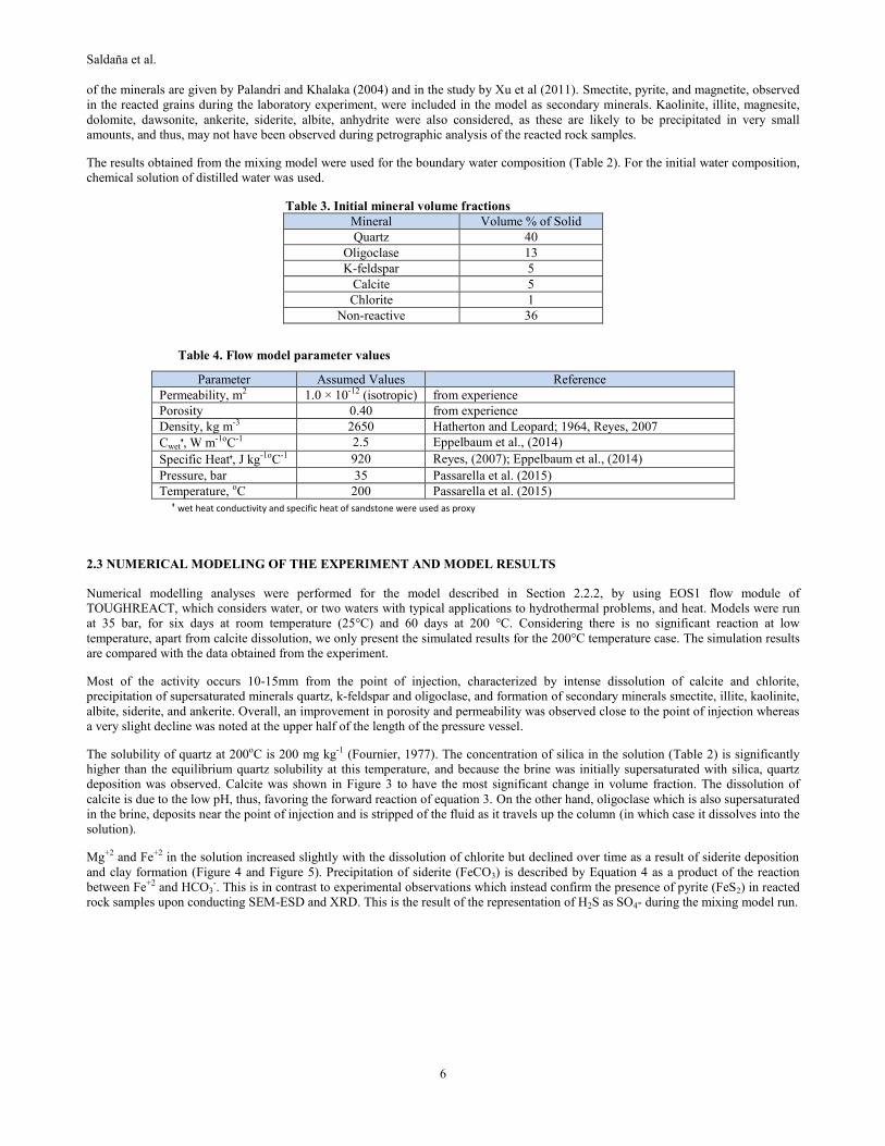
Table 3. Initial mineral volume fractions
Mineral Volume % of Solid
Quartz 40
Oligoclase 13
K-feldspar 5
Calcite 5
Chlorite 1
Non-reactive 36
Table 4. Flow model parameter values
Parameter Assumed Values Reference
Permeability, m2 1.0 × 10⁻¹² (isotropic) from experience
Porosity 0.40 from experience
Density, kg m-3 2650 Hatherton and Leopard; 1964, Reyes, 2007
Cwetᶧ, W m-1oC-1 2.5 Eppelbaum et al., (2014)
Specific Heatᶧ, J kg-1oC-1 920 Reyes, (2007); Eppelbaum et al., (2014)
Pressure, bar 35 Passarella et al. (2015)
Temperature, oC 200 Passarella et al. (2015)
ᶧ wet heat conductivity and specific heat of sandstone were used as proxy
2.3 NUMERICAL MODELING OF THE EXPERIMENT AND MODEL RESULTS
Numerical modelling analyses were performed for the model described in Section 2.2.2, by using EOS1 flow module of
TOUGHREACT, which considers water, or two waters with typical applications to hydrothermal problems, and heat. Models were run
at 35 bar, for six days at room temperature (25°C) and 60 days at 200 °C. Considering there is no significant reaction at low
temperature, apart from calcite dissolution, we only present the simulated results for the 200°C temperature case. The simulation results
are compared with the data obtained from the experiment.
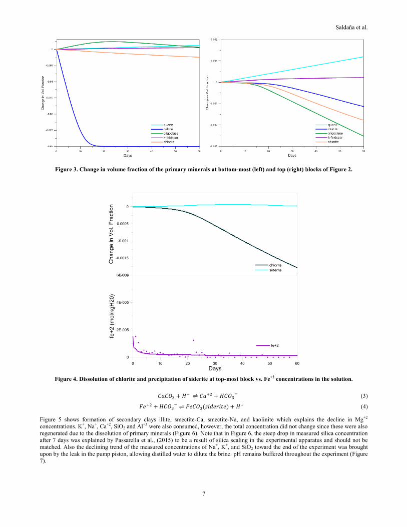
Most of the activity occurs 10-15mm from the point of injection, characterized by intense dissolution of calcite and chlorite,
precipitation of supersaturated minerals quartz, k-feldspar and oligoclase, and formation of secondary minerals smectite, illite, kaolinite,
albite, siderite, and ankerite. Overall, an improvement in porosity and permeability was observed close to the point of injection whereas
a very slight decline was noted at the upper half of the length of the pressure vessel.
The solubility of quartz at 200oC is 200 mg kg-1 (Fournier, 1977). The concentration of silica in the solution (Table 2) is significantly
higher than the equilibrium quartz solubility at this temperature, and because the brine was initially supersaturated with silica, quartz
deposition was observed. Calcite was shown in Figure 3 to have the most significant change in volume fraction. The dissolution of
calcite is due to the low pH, thus, favoring the forward reaction of equation 3. On the other hand, oligoclase which is also supersaturated
in the brine, deposits near the point of injection and is stripped of the fluid as it travels up the column (in which case it dissolves into the
solution).
Mg+2 and Fe+2 in the solution increased slightly with the dissolution of chlorite but declined over time as a result of siderite deposition
and clay formation (Figure 4 and Figure 5). Precipitation of siderite (FeCO3) is described by Equation 4 as a product of the reaction
between Fe+2 and HCO3-. This is in contrast to experimental observations which instead confirm the presence of pyrite (FeS2) in reacted
rock samples upon conducting SEM-ESD and XRD. This is the result of the representation of H2S as SO4- during the mixing model run.
Saldaña et al.
7
Figure 3. Change in volume fraction of the primary minerals at bottom-most (left) and top (right) blocks of Figure 2.
Figure 4. Dissolution of chlorite and precipitation of siderite at top-most block vs. Fe+2 concentrations in the solution.
𝐶𝑎𝐶𝑂3 + 𝐻+ ⇌ 𝐶𝑎+2 + 𝐻𝐶𝑂3− (3)
𝐹𝑒+2 + 𝐻𝐶𝑂3− ⇌ 𝐹𝑒𝐶𝑂3(𝑠𝑖𝑑𝑒𝑟𝑖𝑡𝑒) + 𝐻+ (4)
Figure 5 shows formation of secondary clays illite, smectite-Ca, smectite-Na, and kaolinite which explains the decline in Mg+2
concentrations. K+, Na+, Ca+2, SiO2 and Al+3 were also consumed, however, the total concentration did not change since these were also
regenerated due to the dissolution of primary minerals (Figure 6). Note that in Figure 6, the steep drop in measured silica concentration
after 7 days was explained by Passarella et al., (2015) to be a result of silica scaling in the experimental apparatus and should not be
matched. Also the declining trend of the measured concentrations of Na+, K+, and SiO2 toward the end of the experiment was brought
upon by the leak in the pump piston, allowing distilled water to dilute the brine. pH remains buffered throughout the experiment (Figure
7).

Saldaña et al.
8
Figure 5. Precipitation of secondary minerals at top-most block vs Mg+2 concentration in solution.
Figure 6. Concentration of major cations at top-most (outlet) block of the model.
A net increase in the porosity and permeability was observed in the simulation. Figure 8 shows that much of the change in porosity and
permeability occurred near the injection point, as do other changes such as dissolution of primary minerals and precipitation of clays.
Primary mineral dissolution appears to be the primary mechanism near the point of injection while secondary mineral deposition
dominates at the upper half of the pressure vessel. Looking at these changes, there still appear to be a net increase in porosity and
permeability in the rock sample.

Saldaña et al.
9
Figure 7.pH trend with time at top-most (outlet) block
Figure 8. Permeability and porosity change at the end of model run (60 days) vs sample height
Passarella et al. (2015) noted significant dissolution of the ferromagnesian mineral phases. Dense pyrite coatings (confirmed by XRD
analysis) were observed in close proximity to corroded ferromagnesian phases including chlorite and pyroxene clasts, indicating
relatively fast reaction rates. As mentioned earlier, an improvement of the model will call for the appropriate representation of H2S in
the mixing model in order to allow replication of pyrite deposition, instead of siderite. Therefore, the model was modified with one
significant difference: H2S was assumed to dissolve as HS- instead of SO4-2. Another iteration of pyrite was also chosen from the
thermodynamic database. The result is given in Figure 9. The pyrite model still showed dissolution of chlorite, however, pyrite is now
seen precipitating instead of siderite. The matches for the other mineral and aqueous species were adversely affected, however, in
particular more intense chlorite dissolution and less calcite activity is observed. This resulted in higher Mg+2 concentrations compared
with measured values and faster consumption (decline) of Fe+2.

Saldaña et al.
10
Figure 9. Dissolution of chlorite and precipitation of pyrite and siderite at the top block vs. Fe+2 concentrations in solution,
pyrite model.
5. CONCLUSIONS AND RECOMMENDATIONS
Experiments were conducted to investigate the interaction between greywacke rock, Wairakei brine and representative synthetic NCG,
to assess the reaction rates and evaluate its viability for long term NCG sequestration and permeability enhancement. Numerical
simulations were conducted using TOUGHREACT to model: (1) mixing and speciation of CO2 and H2S in the brine sample; (2)
pumping of brine-gas mixture into the rock substrate at reservoir temperature and pressure conditions.
The mixing model was constructed to obtain initial chemical composition of the brine-NCG mixture, in the absence of measured data.
This was done by assuming complete dissolution of CO2 and H2S into HCO3- and SO4-2, respectively. Considering there is no
significant reaction at low temperature, apart from calcite dissolution, more emphasis was given to the simulation of the 200°C
temperature conditions.
The reactive flow model simulation results show deposition of both quartz and feldspar, which are supersaturated in the injected brine,
and dissolution of calcite, oligoclase, and chlorite. The fluid pH appears to have been buffered by the mineral reactions as the
dissolution of calcite did not cause any change in pH. Secondary clays were also formed, as well as siderite which is a carbonate
mineral. Since the siderite precipitation disagrees with the experimental observations, a separate model was set-up by changing the
reaction parameters in the input files. This resulted in the precipitation of pyrite but affected the matches with the other aqueous species.
There is a net increase in porosity and permeability, which diminishes as one goes further out from the injection point. Among the
carbonate phases considered in the model, only siderite and ankerite precipitated in very minute amounts. This suggests a degree of
sequestration of dissolved CO2 into the mineral phase, however, Xu et al. (2007) have showed that the alteration of primary minerals
and precipitation of secondary carbonates occur at time frames over 100 years and may not be observed during experimental studies.
The results of this simulation can be applied on a larger scale, with larger mass injection, and longer duration to see the long term effect
of CO2 injection in geothermal reservoirs.
The results of these simulations reflect the results of the experiment and provide valuable insights into the consequences of injecting
brine-NCG mixture into a geothermal reservoir. These results are, however, constrained by the limitation of current reactive transport
simulators in representing all complex physical, hydrological, and geochemical processes occurring within the geothermal system,
making data fitting between simulated and experimental results very challenging.

Saldaña et al.
11
REFERENCES
Alfredsson, H. A., & Gislason, S. R. (2009). CarbFix – CO2 sequestration in basaltic rock: chemistry of the rocks and waters at the
injection site. Hellisheidi, SW-Iceland. Goldschmidt Conference Abstracts, A26.
Beni, A., Kuhn, M., Meyer, R., & Clauser, C. (2012). Numerical modeling of a potential geological CO2 sequestration site at Minden
(Germany). Environmental Modeling & Assessment, 17(4), pp. 337-351.
Bischoff, J. L., & Rosenbauer, R. J. (1996). The alteration of rhyolite in CO2 charged water at 200 and 350°C: The unreactivity of CO2
at higher temperature. Geochimica Et Cosmochimica Acta, 60(20), pp. 3859-3867.
Bloomfield, K. K., Moore, J., & Neilson Jr., R. (2003). Geothermal energy reduces greenhouse gases. Bulletin. Geothermal Resources
Council, 32 (2), pp. 77-79.
Browne, P. R. L. (1978). Hydrothermal alteration in active geothermal fields. Annual Review of Earth and Planetary Sciences, 6, pp.
229-250.
Credoz, A., Bildstein, O., Jullien, M., Raynal, J., Pétronin, J., Lillo, M., Pozo, C., & Geniaut, G. (2009). Experimental and modeling
study of geochemical reactivity between clayey caprocks and CO2 in geological storage conditions. Energy Procedia, 1(1), pp.
3445-3452.
Dalkhaa, C., Shevalier, M., Mayer, B., & Nightingale, M. (2013). 2-D Numerical modeling of CO2 storage in the Devonian H2S
containing Nisku aquifer in the Wabamun Lake Area (Alberta, Canada). Energy Procedia, 37, pp. 5331-5338.
DiPippo, R. (2012). Geothermal power plants principles, applications, case studies, and environmental impact (3rd ed.. ed.). Amsterdam
; Boston: Amsterdam ; Boston : Butterworth-Heinemann c2012.
Drysdale, D. (2010). Carbon footprint for the Tauhara stage II geothermal development project. The New Zealand Forest Research
Institute (SCION), Rotorua.
Eppelbaum, L., Kutasov, I., Pilchin, A. (2014). Applied geothermics. Retrieved from: www.springer.com/gp/book/10.1007%2F978-3-
642-34023-9.
Fischer, S., Liebscher, A., Wandrey, M., & CO2SINK Group. (2010). CO2–brine–rock interaction—first results of long-term exposure
experiments at in situ P–T conditions of the Ketzin CO2 reservoir. Chemie Der Erde-Geochemistry, 70, pp. 155-164.
Fournier, R. (1977). Chemical geothermometers and mixing models for geothermal systems. Geothermics, 5(1), pp. 41-50.
Global Carbon Capture and Storage Institute Ltd. (2014) The global status of CCS 2014. Retrieved from www.globalccsinstitute.com/
publications/global-status-ccs-2014
Gunnarsson, I., Aradóttir, E. , Sigfússon, B., Gunnlaugsson, E., & Júlíusson, B. (2013). Geothermal gas emission from Hellisheiði and
Nesjavellir Power Plants, Iceland. Transactions, Geothermal Resources Council, 37 (2) pp. 785-789.
Hamidreza, N. M., Wolf, K. H., & Bruhn, D. (2015). Mixed CO2-water injection into geothermal reservoirs: a numerical study.
Proceedings World Geothermal Congress, 2015.
Hatherton, T., & Leopard, A. E. (1964). The densities of New Zealand rocks. New Zealand Journal of Geology and Geophysics, 7(3),
pp. 605-625.
Holm, A., Jennejohn, D., & Blodgett, L. (2012). Geothermal energy and greenhouse gas emissions. Geothermal Energy Association.
Holubnyak, Y. I., Hawthorne, S. B., Mibeck, B. A., Miller, D. J., Bremer, J. M., Sorensen, J. A., Steadman, E. N., & Harju, J. A. (2011).
Modeling CO2–H2S–water–rock interactions at Williston Basin reservoir conditions. Energy Procedia, 4, pp. 3911-3918.
Hydrogen Sulphide. Public Health England Centre for Radiation, Chemicals and Environmental Hazards. Toxicology Department, 2009
(ver 1). Retrieved from http://www.gov.uk/government/uploads/system/uploads/attachment_data/file/317495/PHE_Compendium_
of_Chemical_Hazards_Hydrogen_Sulphide_v1.pdf
Ingimundarson, A., Arnarson, M., Sighvatsson, H., & Gunnarsson, T. (2015). Design of a H2S absorption column at the Hellisheiði
Powerplant. Proceedings, World Geothermal Congress, 2015.
Jones, B., & Renaut, R. (1998). Origin of platy calcite crystalsin hot-spring deposits in the Kenya Rift Valley. Journal of Sedimentary
Research, 68 (5), pp. 913-927.
Kaieda, H., Ueda, A., Kubota, K., Wakahama, H., Mito, S., Sugiyama, K., Ozawa, A., Kuroda, Y., Sato, H., Yajima, T., Kato, K., Ito,
H., Ohsumi, T., Kaji, Y., & Tokumaru, T. (2009). Field experiments for studying on CO2 sequestration in solid minerals at the
Ogachi HDR geothermal site, Japan. Proceedings 34th Workshop on Geothermal Reservoir Engineering, 2009.
Kaszuba, J. P., Janecky, D. R., & Snow, M. G. (2003). Carbon dioxide reaction processes in a model brine aquifer at 200oC and 200
bars: implications for geologic sequestration of carbon. Applied Geochemistry, 18(7), pp. 1065-1080.
Khasani, Miyazaki, E., & Itoi, R. (2004). Numerical study on effects of CO2 gas in geothermal water on well characteristics.
Proceedings, 2nd International Workshop on Earth Science and Technology, 2004.
Lin, H., Fujii, T., Takisawa, R., Takahashi, T., & Hashida, T. (2008). Experimental evaluation of interactions in supercritical
CO2/water/rock minerals system under geologic CO2 sequestration conditions. Journal of Materials Science, 43(7), pp. 2307-2315.
Luhmann, A. J., Kong, X., Tutolo, B. M., Garapati, N., Bagley, B. C., Saar, M. O., & Seyfried, W. E. (2014). Experimental dissolution
of dolomite by CO2-charged brine at 100° C and 150bar: evolution of porosity, permeability, and reactive surface area. Chemical
Geology, 380, pp. 145-160.
Mahon, W. A. J., McDowell, G. D., & Finlayson, J. B. (1980). Carbon dioxide: its role in geothermal systems. New Zealand Journal of
Science, 23, pp. 133-148.
Mountain, B., & Higgs, K. E. (2015). Simulation of CO2-water-rock interaction in sandstone reservoirs using a continuous flow-through
reactor [unpublished work].
Na, J., Xu, T., Yuan, Y., Feng, B., Tian, H., & Bao, X. (2015). An integrated study of fluid-rock interaction in a CO2-based enhanced
geothermal basin: a case study of Songliao Basin, China. Applied Geochemistry 59 (2015), pp. 166-177.
Nagl, G. (2009). Coso Goethermal Field 15 years of successful H2S abatement. Bulletin. Geothermal Resources Council, 2009.
Papic, P. (1991). Scaling and corrosion potential of selected geothermal waters in Serbia. UNU Geothermal Training Programme, 1991.
Passarella, M., Mountain, B., Zarrouk, S., & Burnell, J. (2015). Experimental simulation of re-injection of non-condensable gases into
geothermal reservoirs: greywacke-fluid interaction. Proceedings, 37th New Zealand Geothermal Workshop, 2015.

Saldaña et al.
12
Plaksina, T., White, C., Nunn, J., & Gray, T. (2011). Effects of coupled convection and CO2 injection in stimulation of geopressured
geothermal reservoirs. Proceedings, 36th Workshop on Geothermal Reservoir Engineering, SGP-TR-191.
Richard, M. A. (1990). The Puna Geothermal Venture Project Power for the Island Of Hawaii. Geothermal Resources Council
Transactions, Vol 14, Part I.
Pruess, K. (2005). ECO2N: A TOUGH2 fluid property module for mixtures of water, NaCl, and CO2. Earth Sciences Division,
Lawrence Berkeley National Laboratory.
Reyes, A. G. (2007). A preliminary evaluation of sources of geothermal energy for direct heat use. GNS Science Report 2007/16.
Salimi, H., Groenenberg, R., & Wolf, K. (2011). Compositional flow simulations of mixed CO2-water injection into geothermal
reservoirs: geothermal energy combined with CO2 storage. 36th Workshop on Geothermal Reservoir Engineering, Stanford
University, pp. 169-181.
Sanopoulos, D., & Karabelas, A. (1997). H2S abatement in geothermal plants: evaluation of process alternatives. Energy Sources, 19(1),
63-77.
Satman, A., Ugur, Z., & Onur, M. (1999). The effect of calcite deposition on geothermal well inflow performance. Geothermics, 28 (3),
pp. 425-444.
Shevalier, M., Nightingale, M., Mayer, B., & Hutcheon, I. (2011). TOUGHREACT modeling of the fate of CO2 injected into a H2S
containing saline aquifer: The example of the Wabamum Area Sequestration Project (WASP). Energy Procedia, 4, pp. 4403-4410.
Shiraki, R., & Dunn, T. L. (2000). Experimental study on water–rock interactions during CO2 flooding in the Tensleep Formation,
Wyoming, USA. Applied Geochemistry, 15(3), pp. 265-279.
Simmons, S., & Christenson, B. (1994). Origins of calcite in a boiling geothermal system. American Journal of Science, 294, pp. 361-
400.
Sonney, R., & Mountain, B. (2013). Experimental simulation of greywacke- fluid interaction under geothermal conditions.
Geothermics, 47, pp. 27-39.
Sung, R., Li, M., Dong, J., Lin, A. T., Hsu, S., Wang, C., & Yang, C. (2014). Numerical assessment of CO2 geological sequestration in
sloping and layered heterogeneous formations: A case study from Taiwan. International Journal of Greenhouse Gas Control,
20(0), pp. 168-179.
Suto, Y., Liu, L., Yamasaki, N., & Hashida, T. (2007). Initial behavior of granite in response to injection of CO2-saturated fluid. Applied
Geochemistry, 22(1), pp. 202-218.
Torres, M. A. B., & Aqui, A. A. (2015). Experimental fluid-rock interaction simulating reinjection of cooling tower condensate in
andesitic-hosted reservoir of Southern Negros Geothermal Field, Philippines.
Truesdell, A., & Nehring, N. (1979). Gases and water isotopes in a geochemical section across the Larderello, Italy, Geothermal Field.
Pure and Applied Geophysics 1978, 117 (1-2), pp. 276-289.
Ueda, A., Kato, K., Ohsumi, T., Yajima, T., Ito, H., Kaieda, H., Metcalfe, R., & Takase, H. (2005). Experimental studies of CO2-rock
interaction at elevated temperatures under hydrothermal conditions. Geochemical Journal; Geochem.J., 39(5), pp. 417-425.
Wellmann, F.J., Croucher, A.,Regenauer-Lieb, K., 2012. Python scripting libraries for subsurface fluid and heat flow simulations with
TOUGH2 and SHEMAT. Comput. Geosci. 43, pp. 197–206.
Wigand, M., Carey, J. W., Schütt, H., Spangenberg, E., & Erzinger, J. (2008). Geochemical effects of CO2 sequestration in sandstones
under simulated in situ conditions of deep saline aquifers. Applied Geochemistry, 23(9), pp. 2735-2745.
Wood, C. P., Brathwaite, R. L., & Rosenberg, M. D. (2001). Basement structure, lithology and permeability at Kawerau and Ohaaki
geothermal fields, New Zealand. Geothermics, 30(4), 461-481.
Xu, T. (2010). Numerical simulation to study the feasibility of using CO2 as a stimulation agent for enhanced geothermal systems.
Lawrence Berkeley National Laboratory.
Xu, T., Apps, J., Pruess, K., & Yamamoto, H. (2007). Numerical modeling of injection and mineral trapping of CO2 with H2S and SO2
in a sandstone formation. Chemical Geology 242, pp. 319-346.
Xu, T., & Pruess, K. (2010). Reactive transport modeling to study fluid-rock interactions in enhanced geothermal systems (EGS) with
CO2 as working fluid. Proceedings, World Geothermal Congress, 2010, pp. 25-29.
Xu, T., Spycher, N., Sonnenthal, E., Zhang, G., Zheng, L., & Pruess, K. (2011). TOUGHREACT Version 2: a simulator for subsurface
reactive transport under non-isothermal multiphase flow conditions. Computers & Geosciences, 37, pp. 763-774.
Yanagisawa, N. (2010). Ca and CO2 transportation and scaling in HDR system. Proceedings World Geothermal Congress, Antalya,
Turkey.