nonlinear whirl response of a high-speed seal test rotor with
TRANSCRIPT
Margaret P. ProctorGlenn Research Center, Cleveland, Ohio
Edgar J. GunterRODYN Vibration Analysis, Inc., Charlottesville, Virginia
Nonlinear Whirl Response of a High-SpeedSeal Test Rotor With Marginal and ExtendedSqueeze-Film Dampers
NASA/TM—2005-213808
August 2005
https://ntrs.nasa.gov/search.jsp?R=20050214756 2018-02-10T20:52:14+00:00Z

The NASA STI Program Office . . . in Profile
Since its founding, NASA has been dedicated tothe advancement of aeronautics and spacescience. The NASA Scientific and TechnicalInformation (STI) Program Office plays a key partin helping NASA maintain this important role.
The NASA STI Program Office is operated byLangley Research Center, the Lead Center forNASA’s scientific and technical information. TheNASA STI Program Office provides access to theNASA STI Database, the largest collection ofaeronautical and space science STI in the world.The Program Office is also NASA’s institutionalmechanism for disseminating the results of itsresearch and development activities. These resultsare published by NASA in the NASA STI ReportSeries, which includes the following report types:
• TECHNICAL PUBLICATION. Reports ofcompleted research or a major significantphase of research that present the results ofNASA programs and include extensive dataor theoretical analysis. Includes compilationsof significant scientific and technical data andinformation deemed to be of continuingreference value. NASA’s counterpart of peer-reviewed formal professional papers buthas less stringent limitations on manuscriptlength and extent of graphic presentations.
• TECHNICAL MEMORANDUM. Scientificand technical findings that are preliminary orof specialized interest, e.g., quick releasereports, working papers, and bibliographiesthat contain minimal annotation. Does notcontain extensive analysis.
• CONTRACTOR REPORT. Scientific andtechnical findings by NASA-sponsoredcontractors and grantees.
• CONFERENCE PUBLICATION. Collectedpapers from scientific and technicalconferences, symposia, seminars, or othermeetings sponsored or cosponsored byNASA.
• SPECIAL PUBLICATION. Scientific,technical, or historical information fromNASA programs, projects, and missions,often concerned with subjects havingsubstantial public interest.
• TECHNICAL TRANSLATION. English-language translations of foreign scientificand technical material pertinent to NASA’smission.
Specialized services that complement the STIProgram Office’s diverse offerings includecreating custom thesauri, building customizeddatabases, organizing and publishing researchresults . . . even providing videos.
For more information about the NASA STIProgram Office, see the following:
• Access the NASA STI Program Home Pageat http://www.sti.nasa.gov
• E-mail your question via the Internet [email protected]
• Fax your question to the NASA AccessHelp Desk at 301–621–0134
• Telephone the NASA Access Help Desk at301–621–0390
• Write to: NASA Access Help Desk NASA Center for AeroSpace Information 7121 Standard Drive Hanover, MD 21076

Margaret P. ProctorGlenn Research Center, Cleveland, Ohio
Edgar J. GunterRODYN Vibration Analysis, Inc., Charlottesville, Virginia
Nonlinear Whirl Response of a High-SpeedSeal Test Rotor With Marginal and ExtendedSqueeze-Film Dampers
NASA/TM—2005-213808
August 2005
National Aeronautics andSpace Administration
Glenn Research Center
Prepared for theThird Biennial International Symposium on Stability Control of RotatingMachinery (ISCORMA–3)sponsored by the Bently Pressurized Bearing CompanyCleveland, Ohio, September 19–23, 2005

Available from
NASA Center for Aerospace Information7121 Standard DriveHanover, MD 21076
National Technical Information Service5285 Port Royal RoadSpringfield, VA 22100
Trade names or manufacturers’ names are used in this report foridentification only. This usage does not constitute an officialendorsement, either expressed or implied, by the National
Aeronautics and Space Administration.
Available electronically at http://gltrs.grc.nasa.gov

NASA/TM—2005-213808 1
Nonlinear Whirl Response of a High-Speed Seal Test Rotor With Marginal and Extended Squeeze-Film Dampers
Margaret P. Proctor
National Aeronautics and Space Administration Glenn Research Center Cleveland, Ohio 44135
Edgar J. Gunter
RODYN Vibration Analysis, Inc. Charlottesville, VA 22903–1560
ABSTRACT
Synchronous and nonsynchronous whirl response analysis of a double overhung, high-speed seal test rotor with ball bearings supported in 5.84- and 12.7-mm-long, un-centered squeeze-film oil dampers is presented. Test performance with the original damper of length 5.84 mm was marginal, with nonsynchronous whirling at the overhung seal test disk and high amplitude synchronous response above 32,000 rpm near the drive spline section occurring. A system critical speed analysis of the drive system and the high-speed seal test rotor indicated that the first two critical speeds are associated with the seal test rotor. Nonlinear synchronous unbalance and time transient whirl studies were conducted on the seal test rotor with the original and extended damper lengths. With the original damper design, the nonlinear synchronous response showed that unbalance could cause damper lockup at 33,000 rpm. Alford cross-coupling forces were also included at the overhung seal test disk for the whirl analysis. Sub-synchronous whirling at the seal test disk was observed in the nonlinear time transient analysis. With the extended damper length of 12.7 mm, the sub-synchronous motion was eliminated and the rotor unbalance response was acceptable to 45,000 rpm with moderate rotor unbalance. However, with high rotor unbalance, damper lockup could still occur at 33,000 rpm, even with the extended squeeze-film dampers. Therefore, the test rotor must be reasonably balanced in order for the un-centered dampers to be effective. NOMENCLATURE C damper radial clearance Cd damping coefficient D damper inner diameter Kb bearing stiffness Kd damper stiffness coefficient Kxy cross coupled stiffness Kyx cross coupled stiffness
L damper length Q aerodynamic cross-coupling coefficient R damper radius Ub unbalance ε eccentricity ratio µ oil viscosity ω angular velocity
INTRODUCTION
NASA has a high temperature, high speed seal rig to test seals over a range of conditions including those expected in advanced gas turbine engines (refs. 5 and 6). The design is similar to certain high-speed aircraft high pressure (HP) gas turbine rotors with squeeze-film oil dampers. The double overhung rotor has a 21.6 cm seal test disk and is supported by rolling element bearings in squeeze film dampers

NASA/TM—2005-213808 2
to provide system damping. The maximum design speed of 43,140 rpm could not be achieved due to high vibration at the seal test disk and at the spline connection to the drive shaft. There were indications of both sub- and super-harmonic whirl motion at the seal test disk and high synchronous response at the balance piston and drive spline. Experimental data indicated both a critical speed and a non-synchronous whirling problem with the rig. DyRoBes, a commercially available rotordynamic analysis package (ref. 3), was used to model and analyze the seal test rotor and its drive system to assess the possible source of and solution to the vibration problem in the seal rig. The rotor system and measurements indicating a vibration problem will be presented as well as the analytical results that show increasing the damper length will improve rotordynamic performance. 1. SEAL TEST ROTOR 1.1 Description of Rotor System and Instrumentation
The seal test rotor, shown in figure 1, consists of a high temperature alloy shaft with two overhung disks. The test rotor is supported in two rolling element bearings. These bearings are in turn supported in squeeze film damper bearings. The 21.6-cm, overhung seal test disk is piloted into the end of the shaft and clamped in place with six studs and retaining nuts. A test end insert is clamped between the seal test disk and the shaft and provides a rotor for a single knife-edge seal, which is part of an air buffer seal that prevents hot gases from reaching the oil-lubricated bearings. A balance piston is mounted on the opposite end of the shaft and is retained by a lock washer and locknut. The split inner race angular contact ball bearings are mounted on the shaft between the two disks and separated by a bearing spacer. They are clamped in position by a shoulder on the shaft and a lock washer and locknut. The bearings are mounted in oil squeeze-film dampers. The drive end of the shaft has an external spline. The drive system consists of a 44.8 kW air turbine and a torque meter connected to each other by a jack shaft with internal, straight splines at both ends. A similar jack shaft connects the torque meter to the seal test rotor. The alignment of the drive system to the seal test rotor is fixed by the housings for the jack shafts, torque meter, and turbine, which pilot to each other and pilot to the seal test rig housing.
Proximity probes are used to observe the seal test rotor’s dynamic performance. Eddy-current proximity probes at the spline and mid-span between the bearings are located at the 9 and 12 o’clock positions, when looking from the seal test disk towards the drive end, to view shaft orbits. For some tests, high-temperature capacitance proximity probes are installed at the 3, 6, 9, and 12 o’clock positions to view the seal test disk orbit and centrifugal growth. The x-y accelerometer pairs are mounted on the seal tester housing near the drive end bearings at the 9 and 12 o’clock positions and on the air turbine at the 12 and 3 o’clock positions. These measurements along with shaft speed are recorded on a digital tape recorder. Orbits are monitored on oscilloscopes. A spectrum analyzer is used to look at the amplitude and frequency content of the signals.

NASA/TM—2005-213808 3
1.2 Vibration and Orbit Measurements Figure 2 represents the seal test rig synchronous x
and y accelerometer versus speed to 34,000 rpm. An apparent vertical resonant mode is observed at 20,000 rpm. A much stronger resonance mode for the X accelerometer occurs at 32,000 rpm. The difference between the vertical and horizontal accelerometer readings is due to the differences in bearing and support horizontal and vertical stiffness and damping values for the two planes. This asymmetric effect is often observed in un-centered dampers with moderate unbalance. Figure 3 shows the synchronous vertical turbine accelerometer amplitude as rotor speed increases. Above 32,000 rpm, a rapid increase in the turbine synchronous response measurement is observed. Also, fractional frequency whirl motion was observed in the turbine orbits at higher speeds. A further increase in the seal test rotor speed to its design speed of 43,140 rpm could have resulted in rig damage.
Figure 4 is an orbit obtained from the seal disk. Note the occurrence of the double loop. Sub-harmonics of one-half and one-third and super-harmonics have been observed. This could be an indication of rubbing. Figure 5 shows a time exposure of the seal test disk motion. The orbital motion indicates impeller whirling. Above 32,000 rpm, the whirl motion increases.

NASA/TM—2005-213808 4
2. CRITICAL SPEED ANALYSIS 2.1 Critical Speed Analysis of Test Rig Including Drive System
As a first step in evaluating the dynamic characteristics of the seal test rig, a model was generated of the entire system including the seal test rotor, drive turbine, torque meter, and spline shafts. Since high vibrations were also encountered at the seal test rotor drive end spline, it was important to determine if the drive system could be a contributing factor. With nominal bearing values selected, the system first undamped critical speed at 21,113 rpm shows the seal test rotor has a conical mode shape as shown in figure 6. Note that figure 2 shows a horizontal resonance around 20,000 rpm. This mode could be a conical whirling of the seal test rotor. With the conical motion, the bearing amplitudes are large and hence high damping should be provided in this mode.
Figure 7 represents the system second critical speed mode at approximately 33,000 rpm. This high amplitude motion at the drive spline could cause the spline to become disconnected. In the second mode, there is more strain energy in bending than in the first mode. The majority of the strain energy for the first mode is in the test rotor bearings. From an examination of the system strain and kinetic energies, it is noted that the first two system modes are related to the seal test rotor and the drive components may be ignored. 2.2 Critical Speed Analysis of Seal Test Rotor
Figure 8 represents a model of the seal test rotor. The un-centered squeeze film dampers used to support the ball bearings are highly nonlinear. However, it is still of value to evaluate the rotor undamped critical speeds in order to determine the rotor mode shapes and the corresponding energy distribution for each mode.

NASA/TM—2005-213808 5
Figure 9 represents critical speeds for the seal test rotor for the first two modes as a function of bearing stiffness. On the critical speed map are drawn the speed lines for 20,000 and 34,000 rpm. With a nominal bearing stiffness value of 175 MN/m, the first critical speed is predicted to be 20,000 rpm. This corresponds to the first frequency as seen in figure 2. As the speed increases, the bearing stiffness increases with loading. The second critical speed is predicted to be 34,000 rpm for an assumed bearing stiffness of 298 MN/m as shown in figure 9.
Figure 10 shows that the first mode is essentially a conical rigid body mode with the seal impeller and the balance piston out of phase. Figure 11 represents the bearing and shaft relative potential or strain energy for this mode. Only 19 percent of the energy is in shaft bending. This also implies that two plane balancing will be sufficient to balance this mode. The test-end bearing contains over 50 percent of the system strain energy and has a major influence on the first critical speed. At higher shaft speeds, this bearing will be the principal bearing that must be modified to control sub-synchronous whirling.
Figure 12 represents the second critical speed mode shape at 31,291 rpm for an assumed bearing stiffness of 175 MN/m. Figure 13 shows the second mode potential energy distribution, which indicates that the test-end damper has little control on the second critical speed. To control the second critical speed and high amplitude observed at the spline, the drive-end bearing must be modified.

NASA/TM—2005-213808 6
3. DYNAMIC ANALYSIS WITH ORIGINAL SQUEEZE FILM DAMPER DESIGN 3.1 Squeeze-Film Dampers
The unbalance response of the seal test rotor with the rolling element bearings mounted in squeeze film dampers is highly nonlinear in nature. The squeeze-film dampers are formed by the geometry of the bearing holder and the outer race of the bearing. The test end squeeze film damper, figure 14, is formed at 7.37-cm diameter, D, has a length, L, of 5.84 mm, and has a radial clearance, C, of 0.051 mm. MIL-23699 oil is supplied to the damper through three oil inlets. The slot in the left end of the bearing holder provides a route for thermocouple wires that measure the bearing outer race temperature. There is no path for the oil to exit the test-end squeeze film damper. The drive-end squeeze film damper has the same dimensions and is mounted in a similar fashion, except that oil can flow through it.
The damper is referred to as an un-centered squeeze film damper since it does not have a mechanical centering spring. The damper design is similar to that encountered in various HP aircraft gas turbine rotors. Therefore, the damper design and test results have significance towards design of damper bearings for various aircraft engine components.
For the analysis of the synchronous unbalance of the test rotor, the bearing assembly is considered as a combination of the rolling element bearing in series with the uncentered squeeze film damper. The damper motion consists of precession but not rotation. Since the damper aspect ratio L/D < 1, the short bearing pi film version of Reynolds equation may be applied. For the case of unbalance response, it is further assumed that the damper motion is circular synchronous precession about the bearing center. This assumption is equivalent to the assumption that the rotating load exceeds the gravitational bearing loading. Under these assumptions, the nonlinear stiffness coefficient is given as follows:
( )( )
3
221
2, ⎟⎠⎞
⎜⎝⎛
ε−
εωµ=ωε
CLRKd (1)
The damper radial stiffness Kd is a function of speed and eccentricity ratio. As the damper orbits outward to larger eccentricities, the damper stiffness increases. At eccentricity ratios above 0.9 the radial damper stiffness becomes quite large and the effective stiffness of the bearing assembly approaches the combined stiffness of the rolling element bearing and the bearing support system.
NASA/TM—2005-213808 7
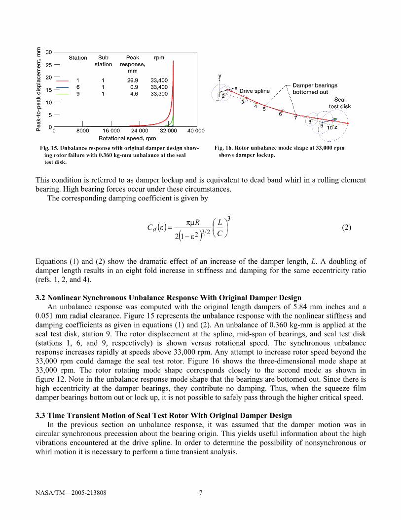
This condition is referred to as damper lockup and is equivalent to dead band whirl in a rolling element bearing. High bearing forces occur under these circumstances.
The corresponding damping coefficient is given by
( )( )
3
23212⎟⎠⎞
⎜⎝⎛
ε−
πµ=ε
CLRCd (2)
Equations (1) and (2) show the dramatic effect of an increase of the damper length, L. A doubling of damper length results in an eight fold increase in stiffness and damping for the same eccentricity ratio (refs. 1, 2, and 4). 3.2 Nonlinear Synchronous Unbalance Response With Original Damper Design
An unbalance response was computed with the original length dampers of 5.84 mm inches and a 0.051 mm radial clearance. Figure 15 represents the unbalance response with the nonlinear stiffness and damping coefficients as given in equations (1) and (2). An unbalance of 0.360 kg-mm is applied at the seal test disk, station 9. The rotor displacement at the spline, mid-span of bearings, and seal test disk (stations 1, 6, and 9, respectively) is shown versus rotational speed. The synchronous unbalance response increases rapidly at speeds above 33,000 rpm. Any attempt to increase rotor speed beyond the 33,000 rpm could damage the seal test rotor. Figure 16 shows the three-dimensional mode shape at 33,000 rpm. The rotor rotating mode shape corresponds closely to the second mode as shown in figure 12. Note in the unbalance response mode shape that the bearings are bottomed out. Since there is high eccentricity at the damper bearings, they contribute no damping. Thus, when the squeeze film damper bearings bottom out or lock up, it is not possible to safely pass through the higher critical speed.
3.3 Time Transient Motion of Seal Test Rotor With Original Damper Design
In the previous section on unbalance response, it was assumed that the damper motion was in circular synchronous precession about the bearing origin. This yields useful information about the high vibrations encountered at the drive spline. In order to determine the possibility of nonsynchronous or whirl motion it is necessary to perform a time transient analysis.

NASA/TM—2005-213808 8
Figure 17 represents the time transient analysis options of the DyRoBes rotor dynamics program for the generalized rotor dynamic motion. In this case the Newmark-Beta method of integration was selected for the numerical procedure. Other options are 4th order Runge-Kutta and the Wilson Theta method. The test rotor has 12 major mass stations. This represents 24 degrees of freedom (DOF) for the x and y motions. In addition, 4 rotational degrees of freedom are included to compute the disk gyroscopic moments of the seal test disk and balance piston. A small time step is used in order to insure numerical stability. The final time of 0.02 seconds represents approximately 12 revolutions of the shaft. As more degrees of freedom are included in a model, smaller time steps must be employed.
In addition to unbalance, gravitational loads are selected as shown in figure 17. In the time transient analysis, the damper forces are computed at each time step based on the damper instantaneous displacement and velocity values. Unlike a linear analysis which employs stiffness and damping coefficients for the damper and may indicate an unstable situation, this nonlinear analysis can show the actual limit cycle motion and more accurately compute the bearing forces transmitted.
Figure 18 shows the transient motion of the seal test disk with a suddenly applied unbalance and an assumed value of aerodynamic cross coupling coefficient of Q = 876 kN/m. This Alford type effect is created by assuming a bearing station at the seal test disk and assigning Kxy = Kyx = Q. The seal test disk orbit shown in figure 18 indicates that the system is sensitive to small cross coupling forces that could be generated in typical seals. Figure 18 also indicates that the maximum orbit may exceed 0.2 mm. This could also lead to seal rubs

NASA/TM—2005-213808 9
which can generate super- as well as sub-harmonic frequencies.
Figure 19 shows the transient test-end damper bearing forces transmitted. These bearing loads are excessive and can result in diminished rolling element bearing life. There is a low frequency component in bearing forces, which indicates whirling. The bearing loading is similar to the loads encountered with a rolling element bearing undergoing dead band whirl with a 0.051 mm clearance. It is apparent from the unbalance response plot of figure 15 and the whirl orbit shown in figure 18 that the dampers are insufficient to provide adequate damping for control of seal test disk whirling or for control of the high amplitude of vibration encountered at the drive spline at the second critical speed. 4. DYNAMIC ANALYSIS WITH ENHANCED SQUEEZE FILM DAMPERS 4.1 Nonlinear Synchronous Unbalance Response With Enhanced Damper Design
An analysis was performed with enhanced dampers in which the damper length increased from 5.84 to 12.7 mm. Figure 20 represents the unbalance response with the enhanced dampers and two planes of unbalance of 0.072 kg-mm at 90° relative phase as shown in figure 21. With the increased damping and the reduced level of unbalance, the response is smooth to 50,000 rpm. Figure 21 represents the synchronous mode shape at 45,000 rpm. The rotor has little bending. 4.2 Time Transient Motion of Seal Test Rig With Enhanced Damper Design
Figure 22 shows the transient response of the seal test rotor at 35,000 rpm with two planes of unbalance and aerodynamic cross-coupling. Note the conical shaft motion with active damper motion. Figure 23 represents the test-end bearing forces transmitted. The initial first forward conical mode rapidly damps out leaving only the synchronous unbalance response. There is no indication of self excited whirl motion present in the transient analysis. Figure 24 represents the transient motion at 45,000 rpm. The motion is stable limit cycle whirl.

NASA/TM—2005-213808 10
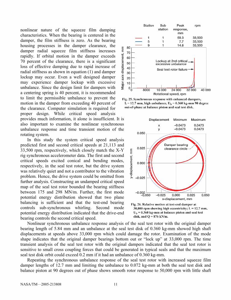
4.3 Synchronous Response With High Two-Plane Unbalance, Ub = 0.360 kg-mm
Figure 25 represents the nonlinear unbalance response if each of the two planes of unbalance are increased from 0.072 to 0.360 kg-mm. Damper lock up will occur at 33,600 rpm. Figure 26 shows the relative test-end damper motion at 30,000 rpm has high eccentricity, further verifying damper lock up. DISCUSSION AND CONCLUSIONS In the design of high speed rotors mounted in rolling element bearings, it is necessary to provide some form of damped flexible support in order to pass through the critical speeds without bearing distress. In addition to the critical speed problem, damping at the bearings or support is also required to prevent self excited whirl motion caused by internal friction or Alford type of forces acting at impellers and balance pistons. A common type of damper employed with rolling element bearings is the squeeze film damper bearing. This bearing-damper configuration is very common in aircraft gas turbine engines. The damper may or may not have a centering spring. The centering spring is needed on heavily loaded rotors to support the gravitational loads. In the case of the seal test rig, the centering spring design was not used. This un-centered design is similar to the design used in many aircraft low pressure and high pressure gas turbine rotors. The design and analysis of this type of bearing is complicated by the
NASA/TM—2005-213808 11
nonlinear nature of the squeeze film damping characteristics. When the bearing is centered in the damper, the film stiffness is zero. As the bearing housing processes in the damper clearance, the damper radial squeeze film stiffness increases rapidly. If orbital motion in the damper exceeds 70 percent of the clearance, there is a significant loss of effective damping due to rapid increase of radial stiffness as shown in equation (1) and damper lockup may occur. Even a well designed damper may experience damper lockup with excessive unbalance. Since the design limit for dampers with a centering spring is 40 percent, it is recommended to limit the permissible unbalance to prevent the motion in the damper from exceeding 40 percent of the clearance. Computer simulation is required for proper design. While critical speed analysis provides much information, it alone is insufficient. It is also important to examine the nonlinear synchronous unbalance response and time transient motion of the rotating system.
In this study the system critical speed analysis predicted first and second critical speeds at 21,113 and 33,500 rpm, respectively, which closely match the X-Y rig synchronous accelerometer data. The first and second critical speeds excited conical and bending modes, respectively, in the seal test rotor, but the drive system was relatively quiet and not a contributor to the vibration problem. Hence, the drive system could be omitted from further analysis. Constructing an undamped critical speed map of the seal test rotor bounded the bearing stiffness between 175 and 298 MN/m. Further, the first mode potential energy distribution showed that two plane balancing is sufficient and that the test-end bearing controls sub-synchronous whirling. Second mode potential energy distribution indicated that the drive-end bearing controls the second critical speed.
Nonlinear synchronous unbalance response analysis of the seal test rotor with the original damper bearing length of 5.84 mm and an unbalance at the seal test disk of 0.360 kg-mm showed high shaft displacements at speeds above 33,000 rpm which could damage the rotor. Examination of the mode shape indicates that the original damper bearings bottom out or “lock up” at 33,000 rpm. The time transient analysis of the seal test rotor with the original dampers indicated that the seal test rotor is sensitive to small cross coupling forces that could be generated in typical seals and that the maximum seal test disk orbit could exceed 0.2 mm if it had an unbalance of 0.360 kg-mm.
Repeating the synchronous unbalance response of the seal test rotor with increased squeeze film damper lengths of 12.7 mm and limiting the unbalance to 0.072 kg-mm at both the seal test disk and balance piston at 90 degrees out of phase shows smooth rotor response to 50,000 rpm with little shaft

NASA/TM—2005-213808 12
bending. The transient response analysis of the seal test rotor with extended dampers at 45,000 rpm show the shaft motion is stable limit cycle whirl. If the two plane unbalance is increased to 0.360 kg-mm then the transient response analysis shows damper lockup at 33,600 rpm. Hence, analysis shows that the seal test rotor can be successfully operated to its maximum design speed of 43,140 rpm if the squeeze film damper lengths are extended to 12.4 mm and the seal test rotor is well balanced.
REFERENCES 1. Barrett, L.E., and Gunter, E.J., Steady State and Transient Analysis of a Squeeze Film Damper
Bearing for Rotor Stability, NASA CR–2548, (1975). 2. Gunter, E.J., Barrett, L.E., Allaire, P.E., Design of Nonlinear Squeeze Film Dampers For Aircraft
Engines, ASME Journal of Lubrication, vol. 92, no. 1 (1977) 57–64. 3. Chen, W.J. and Gunter, E.J., DyRoBes Reference Manual on Rotor Bearing Dynamics, version 9,
RODYN Vibration Analysis, Inc., Charlottesville, VA, 22903 (2004). 4. Chen, W.J. and Gunter, E.J., Introduction to Dynamics of Rotor-Bearing Systems, Trafford
Publishing, Victoria, B.C., Canada, (2005). 5. Proctor, M.P., Kumar, A., and Delgado, I.R., High-Speed, High-Temperature Finger Seal Test
Results, Journal of Propulsion and Power AIAA, vol. 20, no. 2, (2004) 312–318. 6. Proctor, M.P. and Delgado, I.R., Leakage and Power Loss Test Results for Competing Turbine
Engine Seals, NASA/TM—2004-213049, ARL–TR–3157, GT2004–53935, (2004).

This publication is available from the NASA Center for AeroSpace Information, 301–621–0390.
REPORT DOCUMENTATION PAGE
2. REPORT DATE
19. SECURITY CLASSIFICATION OF ABSTRACT
18. SECURITY CLASSIFICATION OF THIS PAGE
Public reporting burden for this collection of information is estimated to average 1 hour per response, including the time for reviewing instructions, searching existing data sources,gathering and maintaining the data needed, and completing and reviewing the collection of information. Send comments regarding this burden estimate or any other aspect of thiscollection of information, including suggestions for reducing this burden, to Washington Headquarters Services, Directorate for Information Operations and Reports, 1215 JeffersonDavis Highway, Suite 1204, Arlington, VA 22202-4302, and to the Office of Management and Budget, Paperwork Reduction Project (0704-0188), Washington, DC 20503.
NSN 7540-01-280-5500 Standard Form 298 (Rev. 2-89)Prescribed by ANSI Std. Z39-18298-102
Form ApprovedOMB No. 0704-0188
12b. DISTRIBUTION CODE
8. PERFORMING ORGANIZATION REPORT NUMBER
5. FUNDING NUMBERS
3. REPORT TYPE AND DATES COVERED
4. TITLE AND SUBTITLE
6. AUTHOR(S)
7. PERFORMING ORGANIZATION NAME(S) AND ADDRESS(ES)
11. SUPPLEMENTARY NOTES
12a. DISTRIBUTION/AVAILABILITY STATEMENT
13. ABSTRACT (Maximum 200 words)
14. SUBJECT TERMS
17. SECURITY CLASSIFICATION OF REPORT
16. PRICE CODE
15. NUMBER OF PAGES
20. LIMITATION OF ABSTRACT
Unclassified Unclassified
Technical Memorandum
Unclassified
National Aeronautics and Space AdministrationJohn H. Glenn Research Center at Lewis FieldCleveland, Ohio 44135–3191
1. AGENCY USE ONLY (Leave blank)
10. SPONSORING/MONITORING AGENCY REPORT NUMBER
9. SPONSORING/MONITORING AGENCY NAME(S) AND ADDRESS(ES)
National Aeronautics and Space AdministrationWashington, DC 20546–0001
Available electronically at http://gltrs.grc.nasa.gov
August 2005
NASA TM—2005–213808
E–15165
WBS–22–714–09–69
18
Nonlinear Whirl Response of a High-Speed Seal Test Rotor With Marginal andExtended Squeeze-Film Dampers
Margaret P. Proctor and Edgar J. Gunter
Nonlinear whirl response; Squeeze-film dampers; Damper lockup; Rotor dynamics
Unclassified -UnlimitedSubject Category: 37
Prepared for the Third Biennial International Symposium on Stability Control of Rotating Machinery (ISCORMA–3)sponsored by the Bently Pressurized Bearing Company, Cleveland, Ohio, September 19–23, 2005. Margaret P. Proctor,e-mail: [email protected], NASA Glenn Research Center; and Edgar J. Gunter, e-mail: [email protected] Vibration Analysis, Inc., 1932 Arlington Blvd., Suite 223, Charlottesville, Virginia 22903–1560. Responsibleperson, Margaret P. Proctor, organization code RSM, 216–977–7526.
Synchronous and nonsynchronous whirl response analysis of a double overhung, high-speed seal test rotor with ballbearings supported in 5.84- and 12.7-mm-long, un-centered squeeze-film oil dampers is presented. Test performance withthe original damper of length 5.84 mm was marginal, with nonsynchronous whirling at the overhung seal test disk andhigh amplitude synchronous response above 32,000 rpm near the drive spline section occurring. A system critical speedanalysis of the drive system and the high-speed seal test rotor indicated that the first two critical speeds are associated withthe seal test rotor. Nonlinear synchronous unbalance and time transient whirl studies were conducted on the seal test rotorwith the original and extended damper lengths. With the original damper design, the nonlinear synchronous responseshowed that unbalance could cause damper lockup at 33,000 rpm. Alford cross-coupling forces were also included at theoverhung seal test disk for the whirl analysis. Sub-synchronous whirling at the seal test disk was observed in the nonlineartime transient analysis. With the extended damper length of 12.7 mm, the sub-synchronous motion was eliminated and therotor unbalance response was acceptable to 45,000 rpm with moderate rotor unbalance. However, with high rotor unbal-ance, damper lockup could still occur at 33,000 rpm, even with the extended squeeze-film dampers. Therefore, the testrotor must be reasonably balanced in order for the un-centered dampers to be effective.

