noaa-n · initial joint polar-orbiting operational satellite system ... cue satellite-aided...
TRANSCRIPT
NOAA-N/1
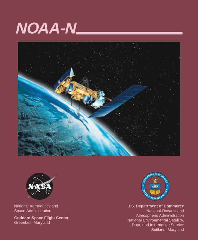
National Aeronautics andSpace Administration
Goddard Space Flight CenterGreenbelt, Maryland
U.S. Department of CommerceNational Oceanic and
Atmospheric AdministrationNational Environmental Satellite,
Data, and Information ServiceSuitland, Maryland
NOAA-N
NOAA-N/2
Table of ContentsPOES Program ............................................................................................................................... 4
The NOAA Polar-Orbiting Satellites................................................................................. 4Initial Joint Polar-Orbiting Operational Satellite System ................................................. 4NOAA-N ........................................................................................................................... 6
NOAA-N Instruments..................................................................................................................... 6Advanced Very High Resolution Radiometer (AVHRR/3) ............................................... 7High Resolution Infrared Radiation Sounder (HIRS/4) .................................................... 7Advanced Microwave Sounding Unit-A (AMSU-A) ........................................................ 8Microwave Humidity Sounder (MHS) .............................................................................. 9Solar Backscatter Ultraviolet Radiometer (SBUV/2)........................................................ 9Space Environment Monitor (SEM-2) ............................................................................ 10Data Collection System (DCS/2)......................................................................................11Search and Rescue (SAR) Instruments............................................................................ 12Digital Data Recorder (DDR) .......................................................................................... 14
Delta II Launch Vehicle ................................................................................................................ 15NOAA-N Orbit ............................................................................................................................. 16Polar Operational Environmental Satellite Products .................................................................... 18Spacecraft Data Communications ................................................................................................ 22
Command and Data Acquisition Station Downlinks ....................................................... 22Direct Broadcast Downlinks............................................................................................ 23Search and Rescue Downlinks ........................................................................................ 24
National Environmental Satellite, Data, and Information Service ............................................... 25Satellite Operations Control Center (SOCC) .................................................................. 25Environmental Satellite Processing Center ..................................................................... 26
Other Support Systems ................................................................................................................. 26Search and Rescue Ground System ................................................................................. 26Goddard Space Flight Center Facility Support ............................................................... 26The North American Aerospace Defense Command (NORAD) ..................................... 27Launch, Early Orbit, and Contingency Downlink ........................................................... 27
Synopsis of Prior Spacecraft ........................................................................................................ 28Appendix A Channel Characteristics ............................................................................................ 32Appendix B Communications and Data Handling ....................................................................... 35Appendix C NOAA-N Activation and Evaluation Timeline ........................................................ 36Glossary ........................................................................................................................................ 38
NOAA-N/3
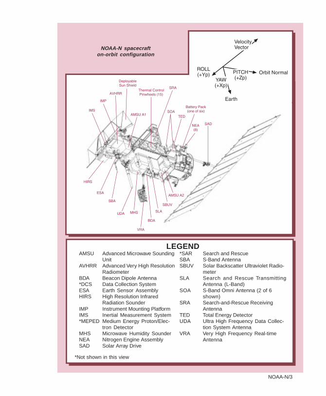
NOAA-N spacecrafton-orbit configuration
*SAR Search and RescueSBA S-Band AntennaSBUV Solar Backscatter Ultraviolet Radio-
meterSLA Search and Rescue Transmitting
Antenna (L-Band)SOA S-Band Omni Antenna (2 of 6
shown)SRA Search-and-Rescue Receiving
AntennaTED Total Energy DetectorUDA Ultra High Frequency Data Collec-
tion System AntennaVRA Very High Frequency Real-time
Antenna
AMSU Advanced Microwave SoundingUnit
AVHRR Advanced Very High ResolutionRadiometer
BDA Beacon Dipole Antenna*DCS Data Collection SystemESA Earth Sensor AssemblyHIRS High Resolution Infrared
Radiation SounderIMP Instrument Mounting PlatformIMS Inertial Measurement System*MEPED Medium Energy Proton/Elec-
tron DetectorMHS Microwave Humidity SounderNEA Nitrogen Engine AssemblySAD Solar Array Drive
LEGEND
*Not shown in this view
NOAA-N/4
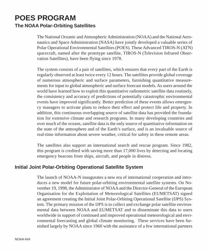
POES PROGRAMThe NOAA Polar-Orbiting Satellites
The National Oceanic and Atmospheric Administration (NOAA) and the National Aero-nautics and Space Administration (NASA) have jointly developed a valuable series ofPolar Operational Environmental Satellites (POES). These Advanced TIROS-N (ATN)spacecraft, named after the prototype satellite, TIROS-N (Television Infrared Obser-vation Satellites), have been flying since 1978.
The system consists of a pair of satellites, which ensures that every part of the Earth isregularly observed at least twice every 12 hours. The satellites provide global coverageof numerous atmospheric and surface parameters, furnishing quantitative measure-ments for input to global atmospheric and surface forecast models. As users around theworld have learned how to exploit this quantitative radiometric satellite data routinely,the consistency and accuracy of predictions of potentially catastrophic environmentalevents have improved significantly. Better prediction of these events allows emergen-cy managers to activate plans to reduce their effect and protect life and property. Inaddition, this continuous overlapping source of satellite data has provided the founda-tion for extensive climate and research programs. In many developing countries andover much of the oceans, satellite data is the only source of quantitative information onthe state of the atmosphere and of the Earth’s surface, and is an invaluable source ofreal-time information about severe weather, critical for safety in these remote areas.
The satellites also support an international search and rescue program. Since 1982,this program is credited with saving more than 17,000 lives by detecting and locatingemergency beacons from ships, aircraft, and people in distress.
Initial Joint Polar-Orbiting Operational Satellite System
The launch of NOAA-N inaugurates a new era of international cooperation and intro-duces a new model for future polar-orbiting environmental satellite systems. On No-vember 19, 1998, the Administrator of NOAA and the Director-General of the EuropeanOrganisation for the Exploitation of Meteorological Satellites (EUMETSAT) signedan agreement creating the Initial Joint Polar-Orbiting Operational Satellite (IJPS) Sys-tem. The primary mission of the IJPS is to collect and exchange polar satellite environ-mental data between NOAA and EUMETSAT and to disseminate this data to usersworldwide in support of continued and improved operational meteorological and envi-ronmental forecasting and global climate monitoring. These services have been fur-nished largely by NOAA since 1960 with the assistance of a few international partners
NOAA-N/5
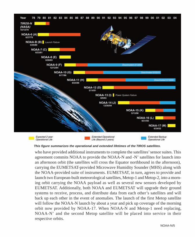
who have provided additional instruments to complete the satellites’ sensor suites. Thisagreement commits NOAA to provide the NOAA-N and -N’ satellites for launch intoan afternoon orbit (the satellites will cross the Equator northbound in the afternoon),carrying the EUMETSAT-provided Microwave Humidity Sounder (MHS) along withthe NOAA-provided suite of instruments. EUMETSAT, in turn, agrees to provide andlaunch two European-built meteorological satellites, Metop-1 and Metop-2, into a morn-ing orbit carrying the NOAA payload as well as several new sensors developed byEUMETSAT. Additionally, both NOAA and EUMETSAT will upgrade their groundsystems to receive, process, and distribute data from each other’s satellites and willback up each other in the event of anomalies. The launch of the first Metop satellitewill follow the NOAA-N launch by about a year and pick up coverage of the morningorbit now provided by NOAA-17. When NOAA-N and Metop-1 need replacing,NOAA-N’ and the second Metop satellite will be placed into service in theirrespective orbits.
This figure summarizes the operational and extended lifetimes of the TIROS satellites.
NOAA-N/6
NOAA-NLockheed Martin Space Systems Company
NOAA-N is the latest satellite in the ATN series built by Lockheed Martin Space Sys-tems Company (LMSSC). This spacecraft will continue to provide a polar-orbitingplatform to support (1) environmental monitoring instruments for imaging and mea-suring the Earth’s atmosphere, itssurface and cloud cover, includingEarth radiation, atmosphericozone, aerosol distribution, seasurface temperature, and verticaltemperature and water profiles inthe troposphere and stratosphere;(2) measurement of proton andelectron flux at orbit altitude; (3)data collection from remote plat-forms; and (4) the Search and Res-cue Satellite-Aided Tracking(SARSAT) system. Additionally,NOAA-N is the fourth in the se-ries to support dedicated micro-wave instruments for thegeneration of temperature, mois-ture, surface, and hydrological products in cloudy regions where visible and infrared(IR) instruments have decreased capability.
NOAA-N INSTRUMENTS
The NOAA-N primary instruments—the Advanced Very High Resolution Radiometer(AVHRR), High Resolution Infrared Radiation Sounder (HIRS), and the AdvancedMicrowave Sounding Unit (AMSU-A)—have all been designed for a three-year mis-sion. Detailed information on each of these instruments, as well as for the Solar Back-scatter Ultraviolet Radiometer (SBUV/2), designed for a two-year mission, and theMicrowave Humidity Sounder (MHS), designed for a five-year mission, is found inAppendix A.
The NOAA-N spacecraft carries the following instruments (manufacturers are shownin italics).
4.19 m (13.75 ft) long, 1.88 m(6.2 ft) diameter
2.73 by 6.14 m (8.96 by 20.16 ft);16.76 m2 (180.63 ft 2)
At lift-off ~1419.8 kg (3130 lb);weight includes 4.1 kg (9 lb) ofgaseous nitrogen
Greater than 2 years
833 W for 0° Sun angle,750 W for 80° Sun angle
Main body:
Solar array:
Weight:
Lifetime:
Load PowerRequirements
NOAA-N CHARACTERISTICS
NOAA-N/7
ADVANCED VERY HIGH RESOLUTION RADIOMETER (AVHRR/3)ITT A/CD
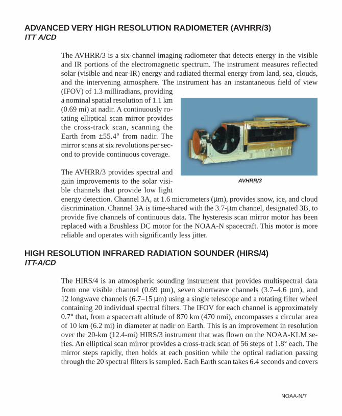
The AVHRR/3 is a six-channel imaging radiometer that detects energy in the visibleand IR portions of the electromagnetic spectrum. The instrument measures reflectedsolar (visible and near-IR) energy and radiated thermal energy from land, sea, clouds,and the intervening atmosphere. The instrument has an instantaneous field of view(IFOV) of 1.3 milliradians, providinga nominal spatial resolution of 1.1 km(0.69 mi) at nadir. A continuously ro-tating elliptical scan mirror providesthe cross-track scan, scanning theEarth from ±55.4° from nadir. Themirror scans at six revolutions per sec-ond to provide continuous coverage.
The AVHRR/3 provides spectral andgain improvements to the solar visi-ble channels that provide low lightenergy detection. Channel 3A, at 1.6 micrometers (µm), provides snow, ice, and clouddiscrimination. Channel 3A is time-shared with the 3.7-µm channel, designated 3B, toprovide five channels of continuous data. The hysteresis scan mirror motor has beenreplaced with a Brushless DC motor for the NOAA-N spacecraft. This motor is morereliable and operates with significantly less jitter.
HIGH RESOLUTION INFRARED RADIATION SOUNDER (HIRS/4)ITT-A/CD
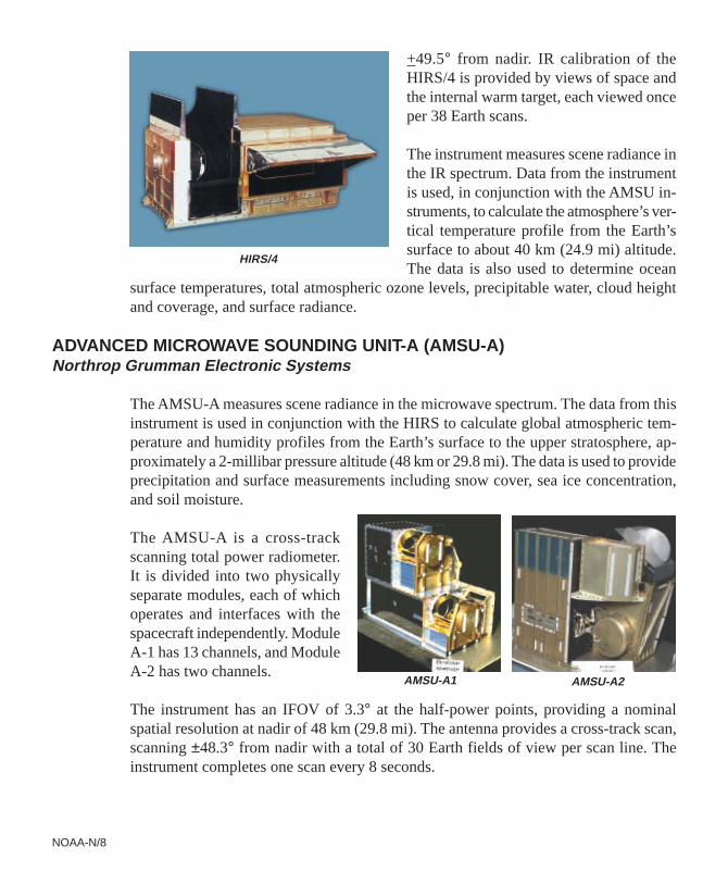
The HIRS/4 is an atmospheric sounding instrument that provides multispectral datafrom one visible channel (0.69 µm), seven shortwave channels (3.7–4.6 µm), and12 longwave channels (6.7–15 µm) using a single telescope and a rotating filter wheelcontaining 20 individual spectral filters. The IFOV for each channel is approximately0.7° that, from a spacecraft altitude of 870 km (470 nmi), encompasses a circular areaof 10 km (6.2 mi) in diameter at nadir on Earth. This is an improvement in resolutionover the 20-km (12.4-mi) HIRS/3 instrument that was flown on the NOAA-KLM se-ries. An elliptical scan mirror provides a cross-track scan of 56 steps of 1.8° each. Themirror steps rapidly, then holds at each position while the optical radiation passingthrough the 20 spectral filters is sampled. Each Earth scan takes 6.4 seconds and covers
AVHRR/3
NOAA-N/8
+49.5° from nadir. IR calibration of theHIRS/4 is provided by views of space andthe internal warm target, each viewed onceper 38 Earth scans.
The instrument measures scene radiance inthe IR spectrum. Data from the instrumentis used, in conjunction with the AMSU in-struments, to calculate the atmosphere’s ver-tical temperature profile from the Earth’ssurface to about 40 km (24.9 mi) altitude.The data is also used to determine ocean
surface temperatures, total atmospheric ozone levels, precipitable water, cloud heightand coverage, and surface radiance.
ADVANCED MICROWAVE SOUNDING UNIT-A (AMSU-A)Northrop Grumman Electronic Systems
The AMSU-A measures scene radiance in the microwave spectrum. The data from thisinstrument is used in conjunction with the HIRS to calculate global atmospheric tem-perature and humidity profiles from the Earth’s surface to the upper stratosphere, ap-proximately a 2-millibar pressure altitude (48 km or 29.8 mi). The data is used to provideprecipitation and surface measurements including snow cover, sea ice concentration,and soil moisture.
The AMSU-A is a cross-trackscanning total power radiometer.It is divided into two physicallyseparate modules, each of whichoperates and interfaces with thespacecraft independently. ModuleA-1 has 13 channels, and ModuleA-2 has two channels.
The instrument has an IFOV of 3.3° at the half-power points, providing a nominalspatial resolution at nadir of 48 km (29.8 mi). The antenna provides a cross-track scan,scanning ±48.3° from nadir with a total of 30 Earth fields of view per scan line. Theinstrument completes one scan every 8 seconds.
AMSU-A1 AMSU-A2
HIRS/4
NOAA-N/9
MICROWAVE HUMIDITY SOUNDER (MHS)EADS Astrium Ltd via EUMETSAT
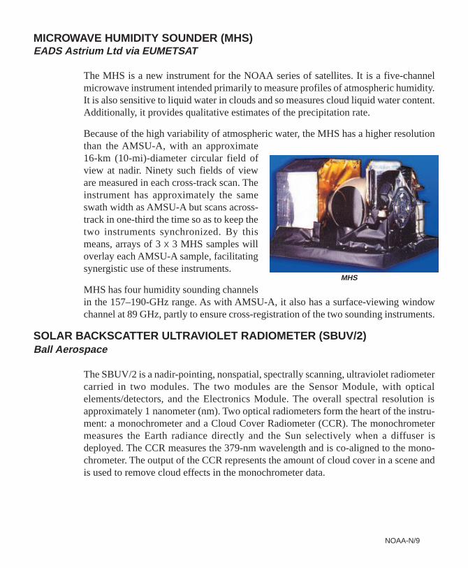
The MHS is a new instrument for the NOAA series of satellites. It is a five-channelmicrowave instrument intended primarily to measure profiles of atmospheric humidity.It is also sensitive to liquid water in clouds and so measures cloud liquid water content.Additionally, it provides qualitative estimates of the precipitation rate.
Because of the high variability of atmospheric water, the MHS has a higher resolutionthan the AMSU-A, with an approximate16-km (10-mi)-diameter circular field ofview at nadir. Ninety such fields of vieware measured in each cross-track scan. Theinstrument has approximately the sameswath width as AMSU-A but scans across-track in one-third the time so as to keep thetwo instruments synchronized. By thismeans, arrays of 3 x 3 MHS samples willoverlay each AMSU-A sample, facilitatingsynergistic use of these instruments.
MHS has four humidity sounding channelsin the 157–190-GHz range. As with AMSU-A, it also has a surface-viewing windowchannel at 89 GHz, partly to ensure cross-registration of the two sounding instruments.
SOLAR BACKSCATTER ULTRAVIOLET RADIOMETER (SBUV/2)Ball Aerospace
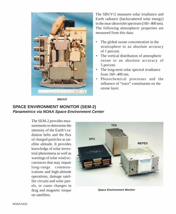
The SBUV/2 is a nadir-pointing, nonspatial, spectrally scanning, ultraviolet radiometercarried in two modules. The two modules are the Sensor Module, with opticalelements/detectors, and the Electronics Module. The overall spectral resolution isapproximately 1 nanometer (nm). Two optical radiometers form the heart of the instru-ment: a monochrometer and a Cloud Cover Radiometer (CCR). The monochrometermeasures the Earth radiance directly and the Sun selectively when a diffuser isdeployed. The CCR measures the 379-nm wavelength and is co-aligned to the mono-chrometer. The output of the CCR represents the amount of cloud cover in a scene andis used to remove cloud effects in the monochrometer data.
MHS
NOAA-N/10
The SBUV/2 measures solar irradiance andEarth radiance (backscattered solar energy)in the near ultraviolet spectrum (160–400 nm).The following atmospheric properties aremeasured from this data:
• The global ozone concentration in thestratosphere to an absolute accuracyof 1 percent.
• The vertical distribution of atmosphericozone to an absolute accuracy of5 percent.
• The long-term solar spectral irradiancefrom 160–400 nm.
• Photochemical processes and theinfluence of “trace” constituents on theozone layer.
SPACE ENVIRONMENT MONITOR (SEM-2)Panametrics via NOAA Space Environment Center
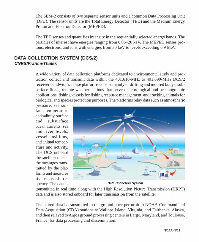
The SEM-2 provides mea-surements to determine theintensity of the Earth’s ra-diation belts and the fluxof charged particles at sat-ellite altitude. It providesknowledge of solar terres-trial phenomena as well aswarnings of solar wind oc-currences that may impairlong-range commun-ications and high-altitudeoperations, damage satel-lite circuits and solar pan-els, or cause changes indrag and magnetic torqueon satellites.
Space Environment Monitor
SBUV/2
TED
MEPED
DPU
NOAA-N/11
The SEM-2 consists of two separate sensor units and a common Data Processing Unit(DPU). The sensor units are the Total Energy Detector (TED) and the Medium EnergyProton and Electron Detector (MEPED).
The TED senses and quantifies intensity in the sequentially selected energy bands. Theparticles of interest have energies ranging from 0.05–20 keV. The MEPED senses pro-tons, electrons, and ions with energies from 30 keV to levels exceeding 6.9 MeV.
DATA COLLECTION SYSTEM (DCS/2)CNES/France/Thales
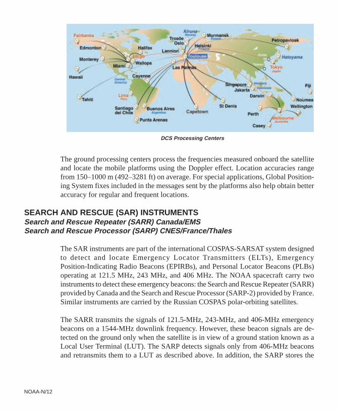
A wide variety of data collection platforms dedicated to environmental study and pro-tection collect and transmit data within the 401.610-MHz to 401.690-MHz DCS/2receiver bandwidth. These platforms consist mainly of drifting and moored buoys, sub-surface floats, remote weather stations that serve meteorological and oceanographicapplications, fishing vessels for fishing resource management, and tracking animals forbiological and species protection purposes. The platforms relay data such as atmosphericpressure, sea sur-face temperatureand salinity, surfaceand subsurfaceocean currents, seaand river levels,vessel positions,and animal temper-ature and activity.The DCS onboardthe satellite collectsthe messages trans-mitted by the plat-forms and measuresits received fre-quency. The data istransmitted in real time along with the High Resolution Picture Transmission (HRPT)data and is also stored onboard for later transmission from the satellite.
The stored data is transmitted to the ground once per orbit to NOAA Command andData Acquisition (CDA) stations at Wallops Island, Virginia, and Fairbanks, Alaska,and then relayed to Argos ground processing centers in Largo, Maryland, and Toulouse,France, for data processing and dissemination.
Data Collection System
NOAA-N/12
The ground processing centers process the frequencies measured onboard the satelliteand locate the mobile platforms using the Doppler effect. Location accuracies rangefrom 150–1000 m (492–3281 ft) on average. For special applications, Global Position-ing System fixes included in the messages sent by the platforms also help obtain betteraccuracy for regular and frequent locations.
SEARCH AND RESCUE (SAR) INSTRUMENTSSearch and Rescue Repeater (SARR) Canada/EMSSearch and Rescue Processor (SARP) CNES/France/Thales
The SAR instruments are part of the international COSPAS-SARSAT system designedto detect and locate Emergency Locator Transmitters (ELTs), EmergencyPosition-Indicating Radio Beacons (EPIRBs), and Personal Locator Beacons (PLBs)operating at 121.5 MHz, 243 MHz, and 406 MHz. The NOAA spacecraft carry twoinstruments to detect these emergency beacons: the Search and Rescue Repeater (SARR)provided by Canada and the Search and Rescue Processor (SARP-2) provided by France.Similar instruments are carried by the Russian COSPAS polar-orbiting satellites.
The SARR transmits the signals of 121.5-MHz, 243-MHz, and 406-MHz emergencybeacons on a 1544-MHz downlink frequency. However, these beacon signals are de-tected on the ground only when the satellite is in view of a ground station known as aLocal User Terminal (LUT). The SARP detects signals only from 406-MHz beaconsand retransmits them to a LUT as described above. In addition, the SARP stores the
DCS Processing Centers
NOAA-N/13
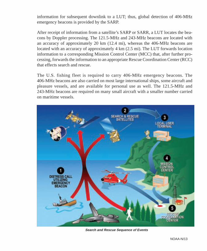
information for subsequent downlink to a LUT; thus, global detection of 406-MHzemergency beacons is provided by the SARP.
After receipt of information from a satellite’s SARP or SARR, a LUT locates the bea-cons by Doppler processing. The 121.5-MHz and 243-MHz beacons are located withan accuracy of approximately 20 km (12.4 mi), whereas the 406-MHz beacons arelocated with an accuracy of approximately 4 km (2.5 mi). The LUT forwards locationinformation to a corresponding Mission Control Center (MCC) that, after further pro-cessing, forwards the information to an appropriate Rescue Coordination Center (RCC)that effects search and rescue.
The U.S. fishing fleet is required to carry 406-MHz emergency beacons. The406-MHz beacons are also carried on most large international ships, some aircraft andpleasure vessels, and are available for personal use as well. The 121.5-MHz and243-MHz beacons are required on many small aircraft with a smaller number carriedon maritime vessels.
Search and Rescue Sequence of Events
NOAA-N/14
DIGITAL DATA RECORDER (DDR)L-3 Communications
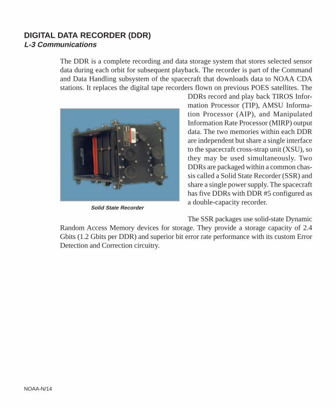
The DDR is a complete recording and data storage system that stores selected sensordata during each orbit for subsequent playback. The recorder is part of the Commandand Data Handling subsystem of the spacecraft that downloads data to NOAA CDAstations. It replaces the digital tape recorders flown on previous POES satellites. The
DDRs record and play back TIROS Infor-mation Processor (TIP), AMSU Informa-tion Processor (AIP), and ManipulatedInformation Rate Processor (MIRP) outputdata. The two memories within each DDRare independent but share a single interfaceto the spacecraft cross-strap unit (XSU), sothey may be used simultaneously. TwoDDRs are packaged within a common chas-sis called a Solid State Recorder (SSR) andshare a single power supply. The spacecrafthas five DDRs with DDR #5 configured asa double-capacity recorder.
The SSR packages use solid-state DynamicRandom Access Memory devices for storage. They provide a storage capacity of 2.4Gbits (1.2 Gbits per DDR) and superior bit error rate performance with its custom ErrorDetection and Correction circuitry.
Solid State Recorder
NOAA-N/15
DELTA II LAUNCH VEHICLEBoeing Space and Defense
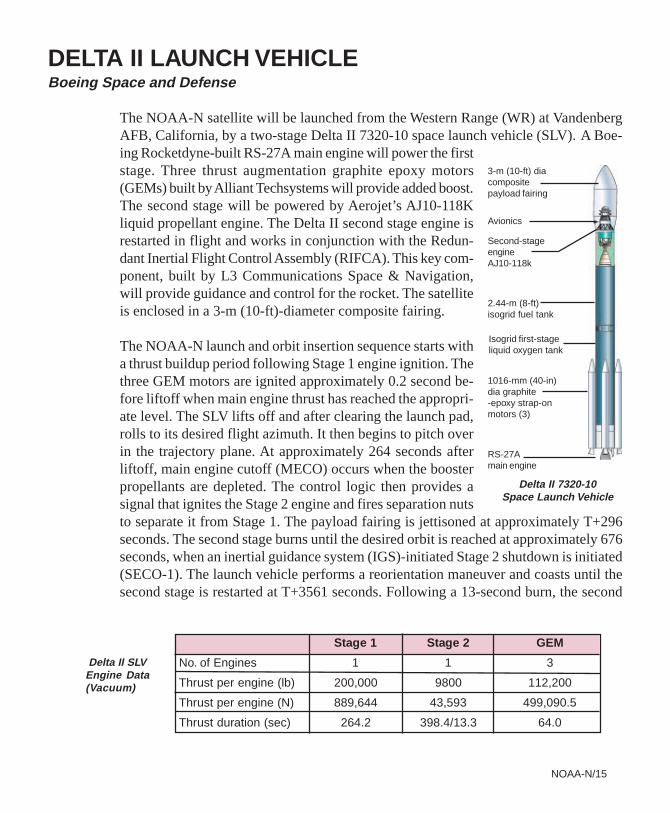
The NOAA-N satellite will be launched from the Western Range (WR) at VandenbergAFB, California, by a two-stage Delta II 7320-10 space launch vehicle (SLV). A Boe-ing Rocketdyne-built RS-27A main engine will power the firststage. Three thrust augmentation graphite epoxy motors(GEMs) built by Alliant Techsystems will provide added boost.The second stage will be powered by Aerojet’s AJ10-118Kliquid propellant engine. The Delta II second stage engine isrestarted in flight and works in conjunction with the Redun-dant Inertial Flight Control Assembly (RIFCA). This key com-ponent, built by L3 Communications Space & Navigation,will provide guidance and control for the rocket. The satelliteis enclosed in a 3-m (10-ft)-diameter composite fairing.
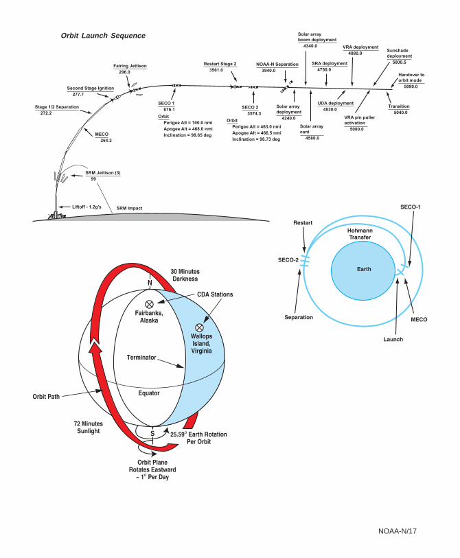
The NOAA-N launch and orbit insertion sequence starts witha thrust buildup period following Stage 1 engine ignition. Thethree GEM motors are ignited approximately 0.2 second be-fore liftoff when main engine thrust has reached the appropri-ate level. The SLV lifts off and after clearing the launch pad,rolls to its desired flight azimuth. It then begins to pitch overin the trajectory plane. At approximately 264 seconds afterliftoff, main engine cutoff (MECO) occurs when the boosterpropellants are depleted. The control logic then provides asignal that ignites the Stage 2 engine and fires separation nutsto separate it from Stage 1. The payload fairing is jettisoned at approximately T+296seconds. The second stage burns until the desired orbit is reached at approximately 676seconds, when an inertial guidance system (IGS)-initiated Stage 2 shutdown is initiated(SECO-1). The launch vehicle performs a reorientation maneuver and coasts until thesecond stage is restarted at T+3561 seconds. Following a 13-second burn, the second
Delta II 7320-10Space Launch Vehicle
3-m (10-ft) diacompositepayload fairing
Avionics
Second-stageengineAJ10-118k
2.44-m (8-ft)isogrid fuel tank
Isogrid first-stageliquid oxygen tank
1016-mm (40-in)dia graphite-epoxy strap-onmotors (3)
RS-27Amain engine
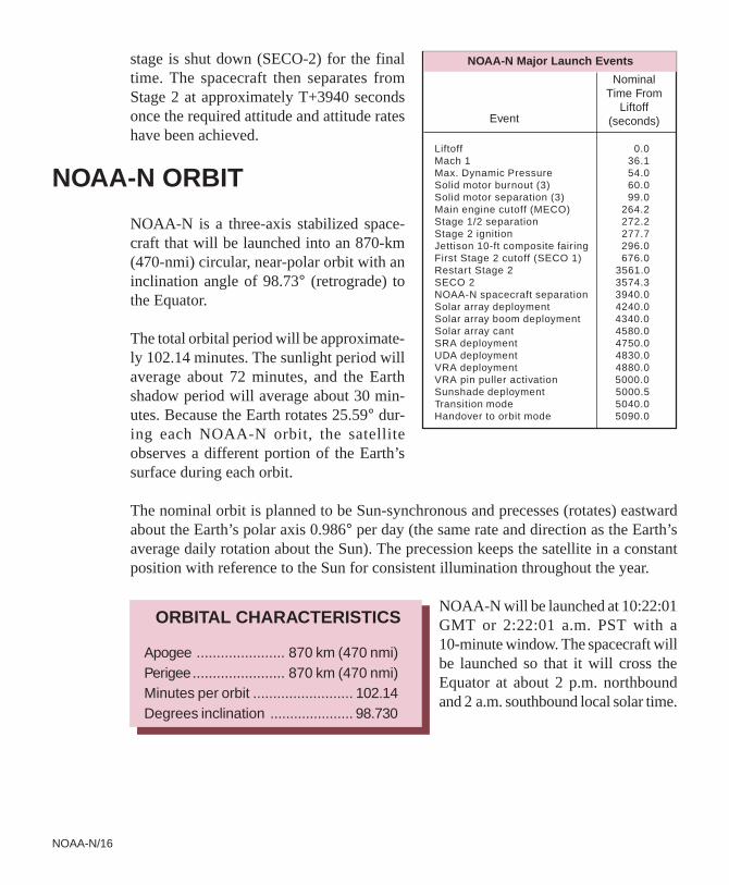
Delta II SLVEngine Data(Vacuum)
Stage 1 Stage 2 GEM
No. of Engines 1 1 3
Thrust per engine (lb) 200,000 9800 112,200
Thrust per engine (N) 889,644 43,593 499,090.5
Thrust duration (sec) 264.2 398.4/13.3 64.0
NOAA-N/16
stage is shut down (SECO-2) for the finaltime. The spacecraft then separates fromStage 2 at approximately T+3940 secondsonce the required attitude and attitude rateshave been achieved.
NOAA-N ORBIT
NOAA-N is a three-axis stabilized space-craft that will be launched into an 870-km(470-nmi) circular, near-polar orbit with aninclination angle of 98.73° (retrograde) tothe Equator.
The total orbital period will be approximate-ly 102.14 minutes. The sunlight period willaverage about 72 minutes, and the Earthshadow period will average about 30 min-utes. Because the Earth rotates 25.59° dur-ing each NOAA-N orbit, the satelliteobserves a different portion of the Earth’ssurface during each orbit.
The nominal orbit is planned to be Sun-synchronous and precesses (rotates) eastwardabout the Earth’s polar axis 0.986° per day (the same rate and direction as the Earth’saverage daily rotation about the Sun). The precession keeps the satellite in a constantposition with reference to the Sun for consistent illumination throughout the year.
NOAA-N will be launched at 10:22:01GMT or 2:22:01 a.m. PST with a10-minute window. The spacecraft willbe launched so that it will cross theEquator at about 2 p.m. northboundand 2 a.m. southbound local solar time.
Liftoff 0.0Mach 1 36.1Max. Dynamic Pressure 54.0Solid motor burnout (3) 60.0Solid motor separation (3) 99.0Main engine cutoff (MECO) 264.2Stage 1/2 separation 272.2Stage 2 ignition 277.7Jettison 10-ft composite fairing 296.0First Stage 2 cutoff (SECO 1) 676.0Restart Stage 2 3561.0SECO 2 3574.3NOAA-N spacecraft separation 3940.0Solar array deployment 4240.0Solar array boom deployment 4340.0Solar array cant 4580.0SRA deployment 4750.0UDA deployment 4830.0VRA deployment 4880.0VRA pin puller activation 5000.0Sunshade deployment 5000.5Transition mode 5040.0Handover to orbit mode 5090.0
Event
NominalTime From
Liftoff(seconds)
NOAA-N Major Launch Events
ORBITAL CHARACTERISTICS
Apogee ...................... 870 km (470 nmi)Perigee....................... 870 km (470 nmi)Minutes per orbit ......................... 102.14Degrees inclination ..................... 98.730
NOAA-N/17
Orbit Launch Sequence
S
NOAA-N/18
POLAR OPERATIONAL ENVIRONMENTALSATELLITE PRODUCTS
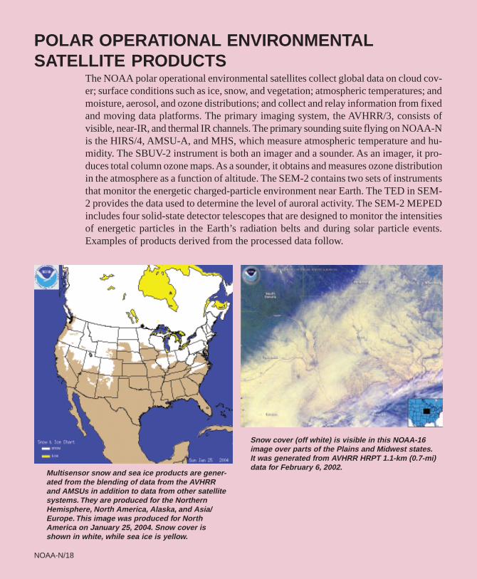
The NOAA polar operational environmental satellites collect global data on cloud cov-er; surface conditions such as ice, snow, and vegetation; atmospheric temperatures; andmoisture, aerosol, and ozone distributions; and collect and relay information from fixedand moving data platforms. The primary imaging system, the AVHRR/3, consists ofvisible, near-IR, and thermal IR channels. The primary sounding suite flying on NOAA-Nis the HIRS/4, AMSU-A, and MHS, which measure atmospheric temperature and hu-midity. The SBUV-2 instrument is both an imager and a sounder. As an imager, it pro-duces total column ozone maps. As a sounder, it obtains and measures ozone distributionin the atmosphere as a function of altitude. The SEM-2 contains two sets of instrumentsthat monitor the energetic charged-particle environment near Earth. The TED in SEM-2 provides the data used to determine the level of auroral activity. The SEM-2 MEPEDincludes four solid-state detector telescopes that are designed to monitor the intensitiesof energetic particles in the Earth’s radiation belts and during solar particle events.Examples of products derived from the processed data follow.
NOAA-N/18
Multisensor snow and sea ice products are gener-ated from the blending of data from the AVHRRand AMSUs in addition to data from other satellitesystems. They are produced for the NorthernHemisphere, North America, Alaska, and Asia/Europe. This image was produced for NorthAmerica on January 25, 2004. Snow cover isshown in white, while sea ice is yellow.
Snow cover (off white) is visible in this NOAA-16image over parts of the Plains and Midwest states.It was generated from AVHRR HRPT 1.1-km (0.7-mi)data for February 6, 2002.
NOAA-N/19NOAA-N/19
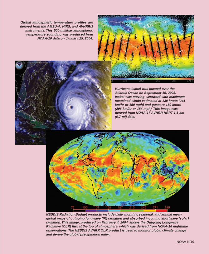
Global atmospheric temperature profiles arederived from the AMSU-A, HIRS, and AVHRR/3
instruments. This 500-millibar atmospherictemperature sounding was produced from
NOAA-16 data on January 25, 2004.
Hurricane Isabel was located over theAtlantic Ocean on September 15, 2003.Isabel was moving westward with maximumsustained winds estimated at 130 knots (241km/hr or 150 mph) and gusts to 160 knots(296 km/hr or 184 mph). This image wasderived from NOAA-17 AVHRR HRPT 1.1-km(0.7-mi) data.
NESDIS Radiation Budget products include daily, monthly, seasonal, and annual meanglobal maps of outgoing longwave (IR) radiation and absorbed incoming shortwave (solar)radiation. This image, produced on February 4, 2004, shows the Outgoing LongwaveRadiative (OLR) flux at the top of atmosphere, which was derived from NOAA-16 nighttimeobservations. The NESDIS AVHRR OLR product is used to monitor global climate changeand derive the global precipitation index.
NOAA-N/20NOAA-N/20
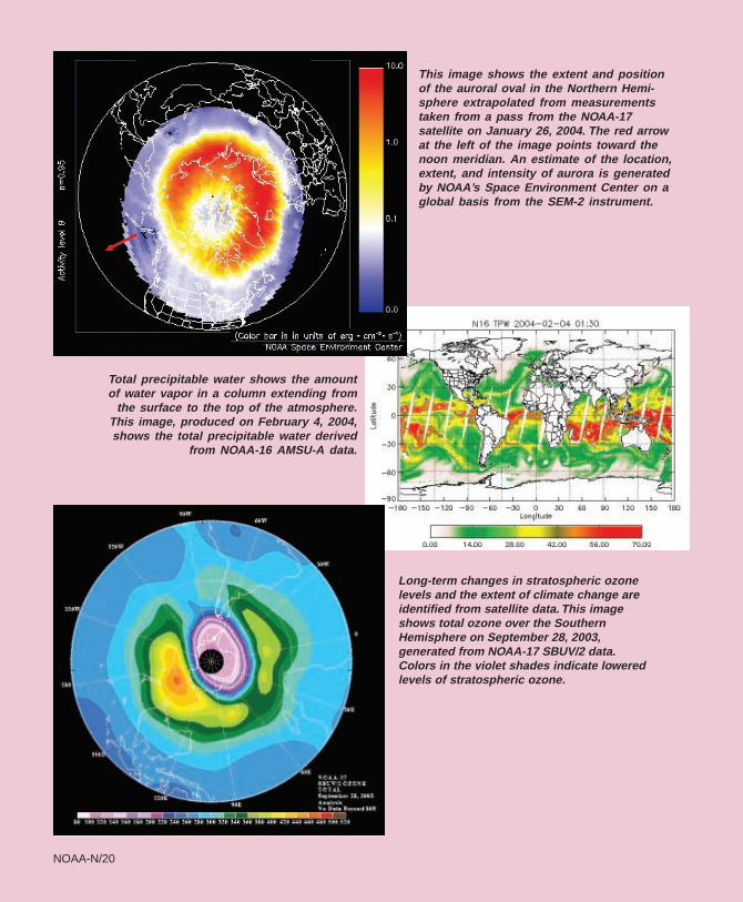
This image shows the extent and positionof the auroral oval in the Northern Hemi-sphere extrapolated from measurementstaken from a pass from the NOAA-17satellite on January 26, 2004. The red arrowat the left of the image points toward thenoon meridian. An estimate of the location,extent, and intensity of aurora is generatedby NOAA’s Space Environment Center on aglobal basis from the SEM-2 instrument.
Total precipitable water shows the amountof water vapor in a column extending from
the surface to the top of the atmosphere.This image, produced on February 4, 2004,shows the total precipitable water derived
from NOAA-16 AMSU-A data.
Long-term changes in stratospheric ozonelevels and the extent of climate change areidentified from satellite data. This imageshows total ozone over the SouthernHemisphere on September 28, 2003,generated from NOAA-17 SBUV/2 data.Colors in the violet shades indicate loweredlevels of stratospheric ozone.
NOAA-N/21NOAA-N/21
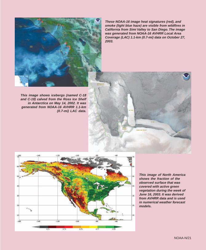
These NOAA-16 image heat signatures (red), andsmoke (light blue haze) are visible from wildfires inCalifornia from Simi Valley to San Diego. The imagewas generated from NOAA-16 AVHRR Local AreaCoverage (LAC) 1.1-km (0.7-mi) data on October 27,2003.
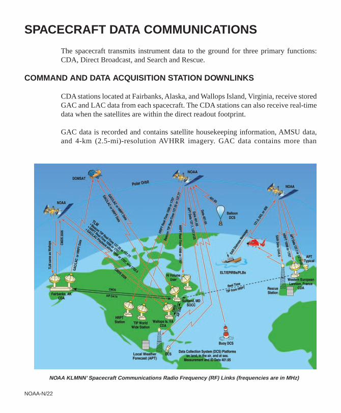
This image shows icebergs (named C-18and C-19) calved from the Ross Ice Shelf
in Antarctica on May 14, 2002. It wasgenerated from NOAA-16 AVHRR 1.1-km
(0.7-mi) LAC data.
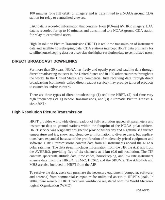
This image of North Americashows the fraction of theobserved surface that wascovered with active greenvegetation during the week ofJune 16, 2003. It was derivedfrom AVHRR data and is usedin numerical weather forecastmodels.
NOAA-N/22
SPACECRAFT DATA COMMUNICATIONS
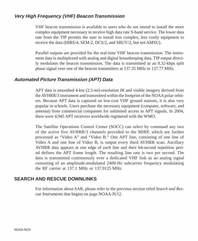
The spacecraft transmits instrument data to the ground for three primary functions:CDA, Direct Broadcast, and Search and Rescue.
COMMAND AND DATA ACQUISITION STATION DOWNLINKS
CDA stations located at Fairbanks, Alaska, and Wallops Island, Virginia, receive storedGAC and LAC data from each spacecraft. The CDA stations can also receive real-timedata when the satellites are within the direct readout footprint.
GAC data is recorded and contains satellite housekeeping information, AMSU data,and 4-km (2.5-mi)-resolution AVHRR imagery. GAC data contains more than
NOAA KLMNN’ Spacecraft Communications Radio Frequency (RF) Links (frequencies are in MHz)
NOAA-N/23
100 minutes (one full orbit) of imagery and is transmitted to a NOAA ground CDAstation for relay to centralized viewers.
LAC data is recorded information that contains 1-km (0.6-mi) AVHRR imagery. LACdata is recorded for up to 10 minutes and transmitted to a NOAA ground CDA stationfor relay to centralized users.
High Resolution Picture Transmission (HRPT) is real-time transmission of instrumentdata and satellite housekeeping data. CDA stations intercept HRPT data primarily forsatellite housekeeping data but also relay the higher resolution data to centralized users.
DIRECT BROADCAST DOWNLINKS
For more than 30 years, NOAA has freely and openly provided satellite data throughdirect broadcasting to users in the United States and in 100 other countries throughoutthe world. In the United States, any commercial firm receiving data through directbroadcasting (commonly called direct readout service) may provide tailored productsto customers and/or viewers.
There are three types of direct broadcasting: (1) real-time HRPT, (2) real-time veryhigh frequency (VHF) beacon transmissions, and (3) Automatic Picture Transmis-sion (APT).
High Resolution Picture Transmission
HRPT provides worldwide direct readout of full-resolution spacecraft parameters andinstrument data to ground stations within the footprint of the NOAA polar orbiters.HRPT service was originally designed to provide timely day and nighttime sea surfacetemperature and ice, snow, and cloud cover information to diverse users, but applica-tions have expanded because of the proliferation of moderately priced equipment andsoftware. HRPT transmissions contain data from all instruments aboard the NOAApolar satellites. The data stream includes information from the TIP, the AIP, and fromthe AVHRR/3, providing five of six channels at 1-km (0.6-mi) resolution. The TIPcontains spacecraft attitude data, time codes, housekeeping, and low rate instrumentscience data from the HIRS/4, SEM-2, DCS/2, and the SBUV/2. The AMSU-A andMHS are also included in HRPT from the AIP.
To receive the data, users can purchase the necessary equipment (computer, software,and antenna) from commercial companies for unlimited access to HRPT signals. In2004, there were 663 HRPT receivers worldwide registered with the World Meteoro-logical Organization (WMO).
NOAA-N/24
Very High Frequency (VHF) Beacon Transmission
VHF beacon transmission is available to users who do not intend to install the morecomplex equipment necessary to receive high data rate S-band service. The lower datarate from the TIP permits the user to install less complex, less costly equipment toreceive the data (HIRS/4, SEM-2, DCS/2, and SBUV/2, but not AMSU).
Parallel outputs are provided for the real-time VHF beacon transmission. The instru-ment data is multiplexed with analog and digital housekeeping data. TIP output direct-ly modulates the beacon transmission. The data is transmitted as an 8.32-kbps splitphase signal over one of the beacon transmitters at 137.35 MHz or 137.77 MHz.
Automated Picture Transmission (APT) Data
APT data is smoothed 4-km (2.5-mi)-resolution IR and visible imagery derived fromthe AVHRR/3 instrument and transmitted within the footprint of the NOAA polar orbit-ers. Because APT data is captured on low-cost VHF ground stations, it is also verypopular in schools. Users purchase the necessary equipment (computer, software, andantenna) from commercial companies for unlimited access to APT signals. In 2004,there were 4,945 APT receivers worldwide registered with the WMO.
The Satellite Operations Control Center (SOCC) can select by command any twoof the active five AVHRR/3 channels provided to the MIRP, which are furtherprocessed as “Video A” and “Video B.” One APT line, consisting of one line ofVideo A and one line of Video B, is output every third AVHRR scan. AncillaryAVHRR data appears at one edge of each line and their 64-second repetition peri-od defines the APT frame length. The resulting line rate is two per second. Thedata is transmitted continuously over a dedicated VHF link as an analog signalconsisting of an amplitude-modulated 2400-Hz subcarrier frequency modulatingthe RF carrier at 137.1 MHz or 137.9125 MHz.
SEARCH AND RESCUE DOWNLINKS
For information about SAR, please refer to the previous section titled Search and Res-cue Instruments that begins on page NOAA-N/12.
NOAA-N/25
NATIONAL ENVIRONMENTAL SATELLITE, DATA,AND INFORMATION SERVICE
SATELLITE OPERATIONS CONTROL CENTER (SOCC)
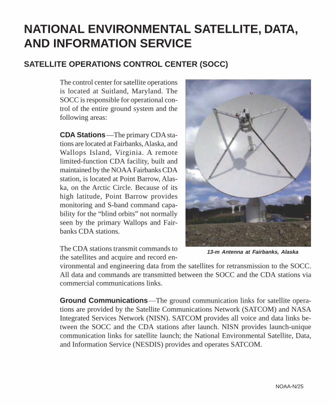
The control center for satellite operationsis located at Suitland, Maryland. TheSOCC is responsible for operational con-trol of the entire ground system and thefollowing areas:
CDA Stations —The primary CDA sta-tions are located at Fairbanks, Alaska, andWallops Island, Virginia. A remotelimited-function CDA facility, built andmaintained by the NOAA Fairbanks CDAstation, is located at Point Barrow, Alas-ka, on the Arctic Circle. Because of itshigh latitude, Point Barrow providesmonitoring and S-band command capa-bility for the “blind orbits” not normallyseen by the primary Wallops and Fair-banks CDA stations.
The CDA stations transmit commands tothe satellites and acquire and record en-vironmental and engineering data from the satellites for retransmission to the SOCC.All data and commands are transmitted between the SOCC and the CDA stations viacommercial communications links.
Ground Communications —The ground communication links for satellite opera-tions are provided by the Satellite Communications Network (SATCOM) and NASAIntegrated Services Network (NISN). SATCOM provides all voice and data links be-tween the SOCC and the CDA stations after launch. NISN provides launch-uniquecommunication links for satellite launch; the National Environmental Satellite, Data,and Information Service (NESDIS) provides and operates SATCOM.
13-m Antenna at Fairbanks, Alaska
NOAA-N/26
ENVIRONMENTAL SATELLITE PROCESSING CENTER (ESPC)
The NESDIS ESPC acquires the data from the CDA stations via the SOCC and isresponsible for data processing and the generation of meteorological products on atimely basis to meet POES program requirements. NOAA provides all hardware andsoftware for ESPC and will provide ephemeris data.
OTHER SUPPORT SYSTEMSSEARCH AND RESCUE GROUND SYSTEM
The United States has recently completed installation of a new generation of LUTs. TheU.S. LUTs are located at Gilmore Creek Command and Data Acquisition Station atFairbanks, Alaska; Vandenberg AFB, California; the U.S. Coast Guard (USCG) Com-munications Station at Wahiawa, Hawaii; the USCG Communications Station at Mi-ami, Florida; NOAA at Suitland, Maryland; and Anderson AFB, Guam.
The LUTs receive SAR data from the NOAA polar and geosynchronous satellites andalso from other low-Earth-orbiting satellites, determine the location of any activateddistress beacons, and forward the data to the U.S. Mission Control Center (USMCC) atSuitland, Maryland. The USMCC first validates the distress situation and then deter-mines the proper RCC. It then forwards the distress location data to the RCC afterremoving redundant information. Additionally, a test ground station is maintained atNASA Goddard Space Flight Center (GSFC) in Greenbelt, Maryland. This system ispart of the worldwide Cospas-Sarsat Program that now consists of 35 countries: 26 ofthese provide MCCs and LUTs, and nine additional countries receive the data. All MCCscooperate in sending data to provide rapid global delivery of distress locations receivedthrough the satellites.
GODDARD SPACE FLIGHT CENTER FACILITY SUPPORT
Support associated with NASA’s Space, Ground, and Deep Space Networks (DSNs) isrequested through the Detailed Mission Requirements documents, with other supportas described in Memoranda of Understanding. NASA GSFC provides nominalprelaunch orbital and prediction information, special support for initial orbit estima-tion, and initial quality control checks of North American Aerospace Defense (NORAD)orbital data. All ground attitude determination is accomplished by the NOAA centraldata processing facility.
NOAA-N/27
THE NORTH AMERICAN AEROSPACE DEFENSE COMMAND (NORAD)
NORAD has prime responsibility for orbit determination, including establishment ofthe initial orbit solution, and providing updated orbital parameters routinely throughoutthe life of the mission.
LAUNCH, EARLY ORBIT, AND CONTINGENCY DOWNLINK
A 2247.5-MHz S-band downlink is used during satellite ascent to recover TIP boosttelemetry through WR tracking sites. From launch through spacecraft separation, WRstations, mobile telemetry, McMurdo NASA Antarctic Interactive Launch Support(NAILS), and Malindi in Kenya will provide spacecraft tracking and telemetry. Fol-lowing spacecraft separation and through spacecraft transition and handover to orbit,the Air Force Satellite Control Network (AFSCN) Telemetry and Command Station(TCS) in Oakhanger, England; the DSN in Madrid, Spain; the AFSCN Thule TrackingStation in Thule, Greenland; and the NOAA Fairbanks CDA facility will provide space-craft tracking and telemetry. The Tracking and Data Relay Satellite System (TDRSS)will provide best-effort tracking and telemetry support on a near-continuous basis fromlaunch through spacecraft separation and handover and transition to orbit mode.
During on-orbit operations, orbit mode TIP will be available for early orbit andcontingency support through the ground tracking network operated by the JetPropulsion Lab (JPL) DSN, which provides contingency command uplink capa-bility. The McMurdo Tracking Facility in Antarctica can also provide contingencyon-orbit telemetry and command support. TDRSS will provide telemetry on a best-effort basis as requested by the Project.
NOAA-N/28
Synopsis of Prior Spacecraft
TIROS-N was launched October 13, 1978, into a 470-nmi (870-km) afternoon orbit. It was the firstsatellite in the fourth generation operational environmental satellite system. TIROS-N was a researchand development spacecraft serving as a protoflight for the operational follow-on series, NOAA-Athrough N’ spacecraft. The satellite was equipped with a four-channel AVHRR, HIRS, Microwave Sound-ing Unit (MSU), Stratospheric Sounding Unit (SSU), SEM, and DCS. TIROS-N was deactivated fol-lowing an Inertial Measurement Unit (IMU) power supply failure on February 27, 1981.
NOAA-A (6) was launched June 27, 1979, into a 450-nmi (833-km) morning orbit. The satellite carriedthe four-channel AVHRR, HIRS/2, MSU, SSU, SEM, and DCS. The HIRS, a primary mission sensor,failed on September 19, 1983. The satellite greatly exceeded its two-year lifetime. It was totally deac-tivated on March 31, 1987, after nearly eight years of operational service.
NOAA-B was launched May 29, 1980. It failed to achieve a usable orbit because of a booster engineanomaly.
NOAA-C (7) was launched June 23, 1981, into a 470-nmi (870-km) afternoon orbit. It carried afive-channel AVHRR rather than the four-channel AVHRR that flew on earlier spacecraft. Other instru-ments were the HIRS/2, MSU, SSU, SEM, and DCS. The HIRS, a primary mission sensor, failed onFebruary 7, 1985. The satellite was deactivated on June 7, 1986, following a failure in the powersystem.
NOAA-E (8) was launched March 28, 1983, into a 450-nmi (833-km) morning orbit. It was the first ofthe ATN satellites and included a stretched structure to provide growth capability. It also included thefirst search and rescue package. In addition, the spacecraft carried a four-channel AVHRR, HIRS/2,MSU, SSU, SEM, and DCS. The redundant crystal oscillator (RXO) failed after 14 months in orbit. TheRXO recovered from its failure, finally locking up on the backup RXO in May 1985. The satellite wasstabilized and declared operational by NOAA on July 1, 1985. The NOAA-8 spacecraft was finally loston December 29, 1985, following a thermal runaway that destroyed a battery.
NOAA-F (9) was launched December 12, 1984, into a 470-nmi (870-km) afternoon orbit. This missiontested the Earth Radiation Budget Experiment (ERBE) and the SBUV radiometer as part of the ex-panded capabilities of the ATN satellites as well as carrying the instruments found on earlier ATNmissions. The ERBE consisted of shortwave and longwave radiometers that were used to study theEarth’s albedo in an attempt to recognize and interpret seasonal and annual climate variations. TheSBUV measured the vertical structure of ozone in the atmosphere. The satellite also had real-timeand global SAR instruments onboard. The MSU, a primary mission sensor, failed on May 7, 1987. TheDigital Tape Recorder (DTR) 1A/1B failed two months after launch. The ERBE scanner stopped out-putting science data in January 1987. Earlier in the mission, the AVHRR periodically exhibited anoma-
NOAA-N/29
lous behavior in its synchronization with the MIRP. The SBUV/2 and the SSU instruments aboardcontinued to operate satisfactorily. The MSU channels 2 and 3 failed, and the satellite’s power systemwas degraded. In August 1995, a very high power overvoltage condition resulted in the failure of theMIRP, the AVHRR, the Battery #1 charge regulator, and the IMU temperature control amplifier. TheMIRP failure also resulted in the loss of the global SAR data via the GAC data stream. The satellite’sability to collect, process, and distribute SBUV/2, SSU, and ERBE-nonscanner data was now limitedto stored TIP data. The SARR transmitter failed on December 18, 1997. The satellite was deactivatedon February 13, 1998.
NOAA-G (10) was launched September 17, 1986, into a 450-nmi (833-km) morning orbit. It carriedthe AVHRR, HIRS/2, MSU, SSU, SEM, DCS, the SARSAT system, and ERBE. The ERBE scannerexhibited a scan-sticking anomaly that was apparently generic to the instrument. The SARP 406-MHzreceiver also failed. The SARP provided global SAR data before its failure. In December 1994, theAVHRR IR channels were damaged and remained severely degraded from a satellite tumble causedby an overflow of the satellite’s ephemeris clock. NOAA-10 was placed in standby mode on Septem-ber 17, 1991 (the date NOAA-12 became fully operational). In January 1997, the MSU scanner dis-played anomalous readings. Telemetry indicated that the digital encoder had failed. The MSU scannermotor was commanded off in February 1997. A MIRP-related missing minor frame anomaly occurredin August 1998. The HRPT data was unusable because of an unstable MIRP and a faulty AVHRR.The satellite was deactivated on August 30, 2001.
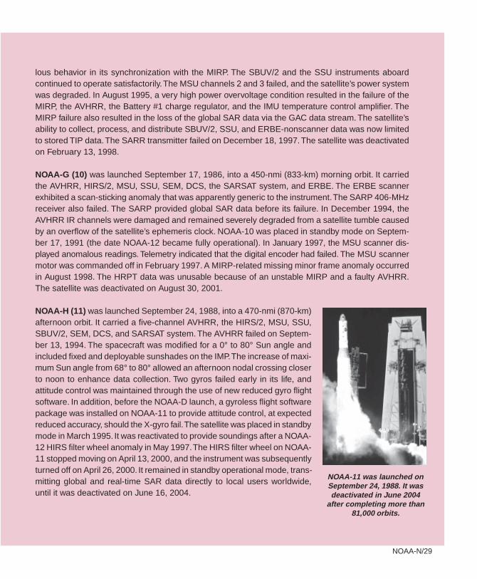
NOAA-H (11) was launched September 24, 1988, into a 470-nmi (870-km)afternoon orbit. It carried a five-channel AVHRR, the HIRS/2, MSU, SSU,SBUV/2, SEM, DCS, and SARSAT system. The AVHRR failed on Septem-ber 13, 1994. The spacecraft was modified for a 0° to 80° Sun angle andincluded fixed and deployable sunshades on the IMP. The increase of maxi-mum Sun angle from 68° to 80° allowed an afternoon nodal crossing closerto noon to enhance data collection. Two gyros failed early in its life, andattitude control was maintained through the use of new reduced gyro flightsoftware. In addition, before the NOAA-D launch, a gyroless flight softwarepackage was installed on NOAA-11 to provide attitude control, at expectedreduced accuracy, should the X-gyro fail. The satellite was placed in standbymode in March 1995. It was reactivated to provide soundings after a NOAA-12 HIRS filter wheel anomaly in May 1997. The HIRS filter wheel on NOAA-11 stopped moving on April 13, 2000, and the instrument was subsequentlyturned off on April 26, 2000. It remained in standby operational mode, trans-mitting global and real-time SAR data directly to local users worldwide,until it was deactivated on June 16, 2004.
NOAA-11 was launched onSeptember 24, 1988. It wasdeactivated in June 2004
after completing more than81,000 orbits.
NOAA-N/30
NOAA-D (12) was launched May 14, 1991, into a 450-nmi (833-km) morning orbit. It replaced NOAA-10 in orbit and carries the same instruments as the earlier spacecraft; however, it does not have a SARpackage or SBUV/2 onboard. The Skew Gyro periodically exhibits a high drift rate, which is correctedwith real-time operational command procedures. In May 1997, the HIRS filter wheel mechanism de-graded to the point that soundings were unusable. The MSU scan motor failed on March 12, 2003. Theremaining instruments and other subsystems continue to operate satisfactorily. NOAA-12 was placedin standby mode on December 14, 1998, when NOAA-15 became operational. It is currently the semi-operational backup morning satellite.
NOAA-I (13) was launched August 9, 1993, into a 470-nmi (870-km) afternoon orbit. On August 21,1993, two weeks after launch, the spacecraft suffered a power system anomaly. All attempts to con-tact or command the spacecraft since the power failure have been unsuccessful.
NOAA-J (14) was launched December 30, 1994, into a 470-nmi (870-km) afternoon orbit. It carries afive-channel AVHRR, the SBUV/2, SSU, HIRS/2, MSU, SEM, SARSAT system, and DCS. In January1995, it was determined that one of the four SEM telescopes had become inoperative, reducing datacollection by 12 percent. In February 1995, the SARP and the SBUV/2 CCR failed, and DTR 4A/4Bwas deemed inoperable. In addition, the ESA exhibited high Quadrant 3 (Q3) data counts due toapparent contamination of the detector. In March 1995, the MSU scanner seized, and the instrumentwas powered off. After three weeks, the MSU was powered on and has been operating satisfactorilyever since. Flight software was modified in April 1995 to correct the high ESA Q3 counts and to turn offthe MSU should the scanner seize up again. Between April 1995 and December 1996, the SBUVgrating drive experienced significant degradation. The grating drive control was reprogrammed tocompensate for these problems as well as for the CCR failure. All other instruments operate satisfac-torily. In November 1995, the demodulator portion of the Command Receiver and Demodulator forOn-board Processor #1 (OBP1) failed, resulting in the loss of the backup OBP. OBP1 was com-manded off. Flight and ground software packages were modified to permit the use of, and command-ing to, only OBP2. On October 18, 2001, the AVHRR scanner became unstable, rendering its imageryunusable. NOAA-16 replaced NOAA-14 as the operational afternoon satellite on March 19, 2001. OnNovember 27, 2003, the SBUV grating motor failed and was powered off. Recovery operations weresuccessful and the unit resumed operations on November 28, 2003. NOAA-14 is now a backup after-noon satellite.
NOAA-K (15) was launched May 13, 1998, into a 450-nmi (833-km) morning orbit. It replaced NOAA-12 on December 14, 1998, as the primary morning spacecraft. It is currently the morning backupsatellite. NOAA-K was the first in the ATN series to support dedicated microwave instruments for thegeneration of temperature, moisture, surface, and hydrological products where visible and IR instru-ments have decreased capability. NOAA-K replaced the MSU of earlier spacecraft with the AMSU-Aand AMSU-B instruments. It also carries a six-channel AVHRR/3, a HIRS/3 and SEM/2, a SARSAT
NOAA-N/31
system, and a DCS. The S-band transmitter (STX)-1, STX-2, and STX-3 high-gain antennas haveshown degraded performance in orbit. Beginning September 28, 1999, the satellite was configured totransmit HRPT using the STX-2 omnidirectional antenna and transmit data playbacks using STX-4.The STX-1 and STX-3 downlinks are not used. Since launch, the AMSU-B instrument has had abias in the science data that has been corrected by software processing on the ground. This bias iscaused by interference from on-board L-band and S-band transmit systems. With the use of the omni-directional antennas and only the STX-2 and STX-4 downlinks, the interference can be modeled toremove the bias to the science data. AMSU-B instruments on NOAA-16 and later spacecraft havebeen modified to correct this bias. Gyro 3 was turned off in June 2000, because of excessive drift inthe gyro. The AVHRR scan motor is showing degraded performance that began on May 30, 2000, andAVHRR products are marginally usable. The AMSU-A1 Channels 14 and 11 have failed. Other AMSU-A1 channels are fine. The SARR 243-MHz receive system developed a thermal-related intermittentfailure beginning on December 5, 2000. An antenna subsystem is the most likely cause. A HIRS filtermotor anomaly, which first occurred in December 1999, recovered in January 2001. Surges with thefilter motor occurred throughout 2002. The HIRS has had a problem with its filter motor current andtemperature beginning on February 1, 2003, which negatively affected the radiometry.
NOAA-L (16) was launched on September 21, 2000, into a 470-nmi (870-km) afternoon orbit. Itreplaced NOAA-14 on March 19, 2001, as the primary afternoon spacecraft. It carries the sameinstruments as NOAA-15 with the addition of the SBUV/2. The APT VHF downlink showed a se-verely degraded performance starting on November 13, 2000. A hybrid failure in the VRA antennasubsystem was the most likely cause. The APT downlink was commanded off on February 26, 2001.A HIRS instrument cross-track pointing error has been observed since launch. The problem wastraced to a procedural error during the instrument’s scan mirror installation. Data processing proce-dures were developed to correct for instrument misalignment. The SARR 243-MHz receive systemdeveloped what is believed to be a thermally induced failure in the antenna (SRA). The STX-3 outputpower dropped to 1 watt on September 28, 2001. The link is still usable by the NOAA CDA station.On September 17, 2003, the AVHRR began to show evidence of scan motor degradation. Thecondition worsened in early 2004 and products are being intermittently affected. NOAA-16 is cur-rently the designated operational afternoon satellite.
NOAA-M (17) was launched on June 24, 2002, into a 450-nmi (833 km) morning orbit. It replacedNOAA-15 on October 15, 2002, as the primary morning spacecraft and is currently the designatedoperational morning satellite. It carries the same instruments as NOAA-16. On April 28, 2003, theSTX-3 output dropped to 2.48 W. Link margin is still sufficient for most users. On October 30, 2003,AMSU-A1 powered off because of a scan motor failure. All other instruments and subsystems con-tinue in full operational mode. NOAA-17 is currently the designated operational morning satellite.
NOAA-N/32
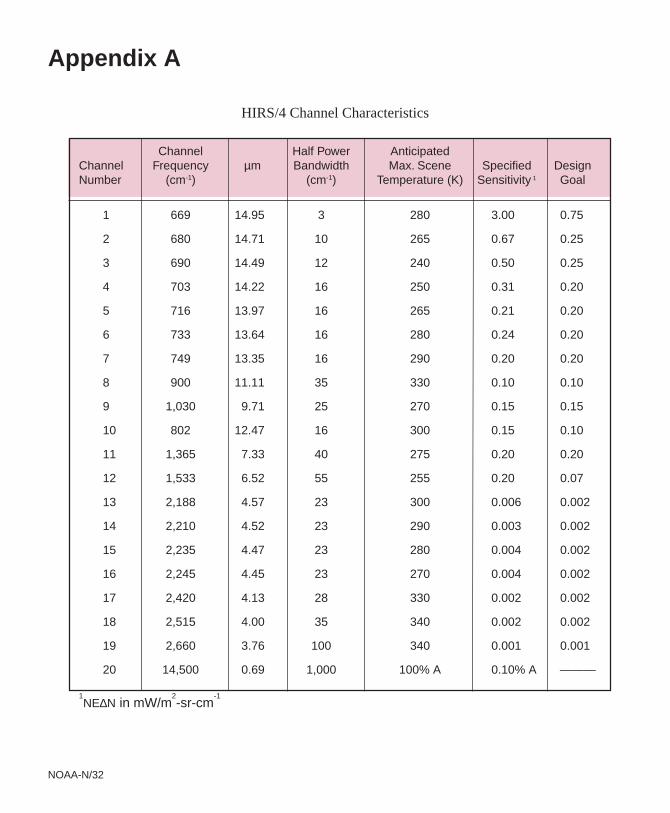
Appendix A
Channel Half Power AnticipatedChannel Frequency µm Bandwidth Max. Scene Specified DesignNumber (cm-1) (cm-1) Temperature (K) Sensitivity 1 Goal
1 669 14.95 3 280 3.00 0.75
2 680 14.71 10 265 0.67 0.25
3 690 14.49 12 240 0.50 0.25
4 703 14.22 16 250 0.31 0.20
5 716 13.97 16 265 0.21 0.20
6 733 13.64 16 280 0.24 0.20
7 749 13.35 16 290 0.20 0.20
8 900 11.11 35 330 0.10 0.10
9 1,030 9.71 25 270 0.15 0.15
10 802 12.47 16 300 0.15 0.10
11 1,365 7.33 40 275 0.20 0.20
12 1,533 6.52 55 255 0.20 0.07
13 2,188 4.57 23 300 0.006 0.002
14 2,210 4.52 23 290 0.003 0.002
15 2,235 4.47 23 280 0.004 0.002
16 2,245 4.45 23 270 0.004 0.002
17 2,420 4.13 28 330 0.002 0.002
18 2,515 4.00 35 340 0.002 0.002
19 2,660 3.76 100 340 0.001 0.001
20 14,500 0.69 1,000 100% A 0.10% A ———
1NE∆N in mW/m
2-sr-cm
-1
HIRS/4 Channel Characteristics
NOAA-N/33
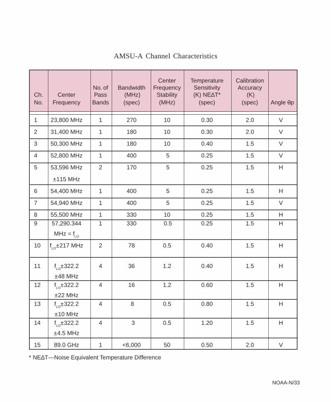
AMSU-A Channel Characteristics
Center Temperature CalibrationNo. of Bandwidth Frequency Sensitivity Accuracy
Ch. Center Pass (MHz) Stability (K) NE∆T* (K)No. Frequency Bands (spec) (MHz) (spec) (spec) Angle 0p
1 23,800 MHz 1 270 10 0.30 2.0 V
2 31,400 MHz 1 180 10 0.30 2.0 V
3 50,300 MHz 1 180 10 0.40 1.5 V
4 52,800 MHz 1 400 5 0.25 1.5 V
5 53,596 MHz 2 170 5 0.25 1.5 H
±115 MHz
6 54,400 MHz 1 400 5 0.25 1.5 H
7 54,940 MHz 1 400 5 0.25 1.5 V
8 55,500 MHz 1 330 10 0.25 1.5 H
9 57,290.344 1 330 0.5 0.25 1.5 H
MHz = fLO
10 fLO±217 MHz 2 78 0.5 0.40 1.5 H
11 fLO±322.2 4 36 1.2 0.40 1.5 H
±48 MHz
12 fLO±322.2 4 16 1.2 0.60 1.5 H
±22 MHz
13 fLO±322.2 4 8 0.5 0.80 1.5 H
±10 MHz
14 fLO±322.2 4 3 0.5 1.20 1.5 H
±4.5 MHz
15 89.0 GHz 1 <6,000 50 0.50 2.0 V
* NE∆T—Noise Equivalent Temperature Difference

NOAA-N/34
MHS Channel Characteristics
AVHRR/3 Channel Characteristics
1 0.58 - 0.68 9:1 @ 0.5% Albedo 1.09 0 - 25 0 - 50026 - 100 501 - 1000
2 0.725 - 1.00 9:1 @ 0.5% Albedo 1.09 0 - 25 0 - 50026 - 100 501 - 1000
3A 1.58 - 1.64 20:1 @ 0.5% Albedo 1.09 0 - 12.5 0 - 50012.6 - 100 501 - 1000
NE∆T Max Scene Temp K
3B 3.55 - 3.93 0.12 @ 300K Scene 1.094 10.30 - 11.30 0.12 @ 300K Scene 1.095 11.50 - 12.50 0.12 @ 300K Scene 1.09
(50% Points)Max
Channel Spectral Band Signal-to-Noise-Ratio Res. Albedo CountsNumber Micrometers SSP km Range % Range
ChannelNumber
Center Frequency
(GHz)
H1H2H3H4H5
89.0157.0
183.311 ± 1.0183.311 ± 3.0
190.311
Wavelength (nm)
252.00273.61283.1287.7292.29297.59301.97305.87312.57317.56331.26339.89
Description
Discrete Pos. 0Discrete Pos. 1Discrete Pos. 2Discrete Pos. 3Discrete Pos. 4Discrete Pos. 5Discrete Pos. 6Discrete Pos. 7Discrete Pos. 8Discrete Pos. 9Discrete Pos. 10Discrete Pos. 11
SBUV Discrete Ozone Position
RF Bandwidth
(MHz)
Temperature Sensitivity
NE∆T (K)
Spec Goal Polarization
2x11002x11002x500
2x10002x1000
1.0 0.61.0 0.61.0 0.61.0 0.61.0 0.6
VVHHV
Channel Number
0123456789
1011
335335335
NOAA-N/35
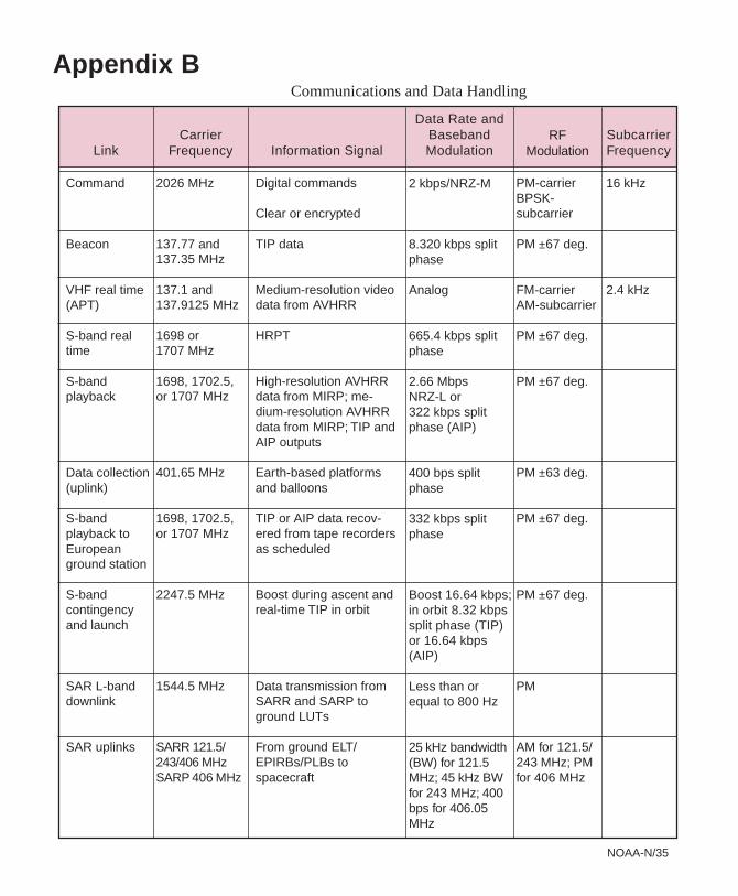
Appendix BCommunications and Data Handling
RFModulationLink
CarrierFrequency Information Signal
Data Rate andBasebandModulation
SubcarrierFrequency
Command
Beacon
VHF real time(APT)
S-band realtime
S-bandplayback
Data collection(uplink)
S-bandplayback toEuropeanground station
S-bandcontingencyand launch
SAR L-banddownlink
SAR uplinks
2026 MHz
137.77 and137.35 MHz
137.1 and137.9125 MHz
1698 or1707 MHz
1698, 1702.5,or 1707 MHz
401.65 MHz
1698, 1702.5,or 1707 MHz
2247.5 MHz
1544.5 MHz
SARR 121.5/243/406 MHzSARP 406 MHz
Digital commands
Clear or encrypted
TIP data
Medium-resolution videodata from AVHRR
HRPT
High-resolution AVHRRdata from MIRP; me-dium-resolution AVHRRdata from MIRP; TIP andAIP outputs
Earth-based platformsand balloons
TIP or AIP data recov-ered from tape recordersas scheduled
Boost during ascent andreal-time TIP in orbit
Data transmission fromSARR and SARP toground LUTs
From ground ELT/EPIRBs/PLBs tospacecraft
2 kbps/NRZ-M
8.320 kbps splitphase
Analog
665.4 kbps splitphase
2.66 MbpsNRZ-L or322 kbps splitphase (AIP)
400 bps splitphase
332 kbps splitphase
Boost 16.64 kbps;in orbit 8.32 kbpssplit phase (TIP)or 16.64 kbps(AIP)
Less than orequal to 800 Hz
25 kHz bandwidth(BW) for 121.5MHz; 45 kHz BWfor 243 MHz; 400bps for 406.05MHz
PM-carrierBPSK-subcarrier
PM ±67 deg.
FM-carrierAM-subcarrier
PM ±67 deg.
PM ±67 deg.
PM ±63 deg.
PM ±67 deg.
PM ±67 deg.
PM
AM for 121.5/243 MHz; PMfor 406 MHz
16 kHz
2.4 kHz
NOAA-N/36
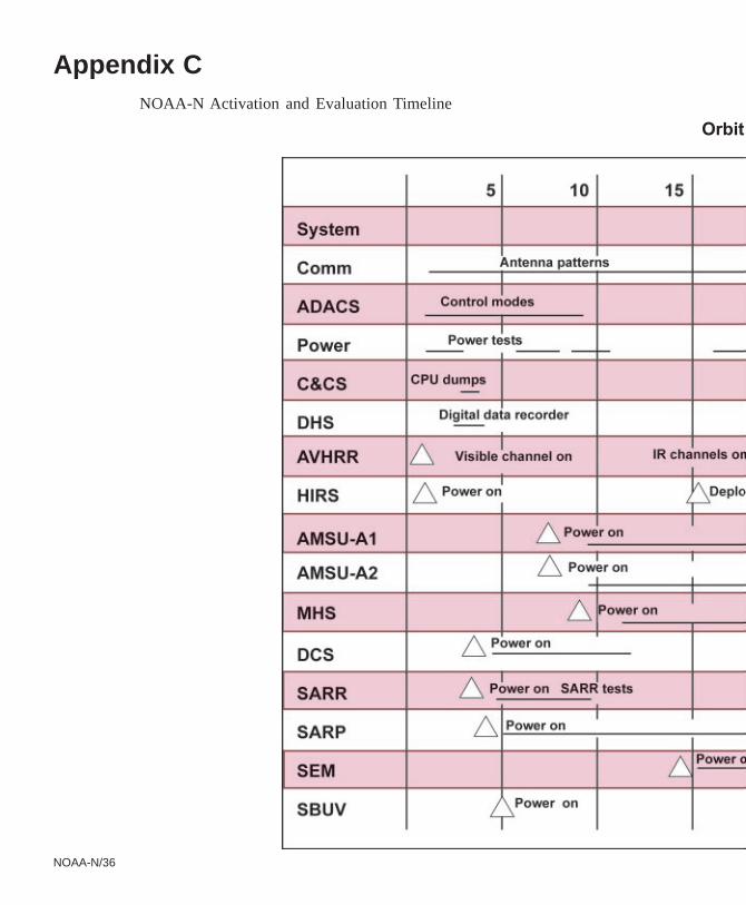
Appendix C NOAA-N Activation and Evaluation Timeline
Orbit
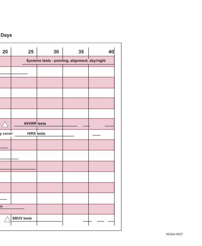
NOAA-N/37
Days
NOAA-N/38
ADACS Attitude Determination and ControlSystem
AFB Air Force Base
AFSCN Air Force Satellite Control Network
AIP AMSU Information Processor
Alt Altitude
AM Amplitude Modulation
AMSU Advanced Microwave Sounding Unit
APT Automatic Picture Transmission
ATN Advanced TIROS-N
AVHRR Advanced Very High ResolutionRadiometer
BDA Beacon Dipole Antenna
bps Bits Per Second
BW Bandwidth
C&CS Command and Control Subsystem
CCR Cloud Cover Radiometer
CDA Command and Data Acquisition
cm Centimeter
CNES Centre National d’Etudes Spatiales
COSPAS Russian Space Systems for the Searchof Vessels in Distress
DCS Data Collection System
DDR Digital Data Recorder
DPU Data Processing Unit
DSN Deep Space Network
DTR Digital Tape Recorder
ELT Emergency Locator Transmitter
EPIRB Emergency Position-Indicating RadioBeacon
ERBE Earth Radiation Budget Experiment
ESA Earth Sensor Assembly
ESPC Environmental Satellite ProcessingCenter
EUMETSAT European Organisation for theExploitation of Meteorological Satellites
FM Frequency Modulation
ft Feet
GAC Global Area Coverage
Gbit Gigabit
GEM Graphite Epoxy Motor
GHz Gigahertz
GMT Greenwich Mean Time
GSFC Goddard Space Flight Center
HIRS High Resolution Infrared RadiationSounder
HRPT High Resolution Picture Transmission
Hz Hertz
IFOV Instantaneous Field of View
IGS Inertial Guidance System
IJPS Initial Joint Polar-Orbiting OperationalSatellite System
IMP Instrument Mounting Platform
IMS Inertial Measurement System
IMU Inertial Measurement Unit
in Inch
IR Infrared
ITT ITT Aerospace/Communications Division
JPL Jet Propulsion Lab
K Kelvin temperature
kbps Kilo bits per second
keV Kiloelectron volts
kg Kilogram
kHz Kilohertz
km Kilometer
LAC Local Area Coverage
lb Pound
LMSSC Lockheed Martin Space SystemsCompany
LUT Local User Terminal
Mbps Mega bits per second
MCC Mission Control Center
MECO Main Engine Cutoff
MEPED Medium Energy Proton/Electron Detector
MeV Million electron volt(s)
MHS Microwave Humidity Sounder
MHz Megahertz
mi Mile
MIRP Manipulated Information Rate Processor
GLOSSARY
NOAA-N/3
mph miles per hour
mps meters per second
ms Millisecond
MSU Microwave Sounding Unit
N Newton
NAILS NASA Antarctic Interactive Launch Support
NASA National Aeronautics and SpaceAdministration
NEA Nitrogen Engine Assembly
NE∆∆∆∆∆N Noise Equivalent Radiance
NE∆∆∆∆∆T Noise Equivalent Temperature Difference
NESDIS National Environmental Satellite, Data, andInformation Service
NISN NASA Integrated Services Network
nm Nanometer(s)
nmi Nautical mile
NOAA National Oceanic and AtmosphericAdministration
NORAD North American Aerospace DefenseCommand
NRZ Non-Return to Zero
OBP1 On-Board Processor #1
OLR Outgoing Longwave Radiation
PLB Personal Locator Beacon
PM Phase Modulated
POES Polar Operational Environmental Satellites
PSK Phase Shift Keyed
PST Pacific Standard Time
Q3 Quadrant 3
RCC Rescue Coordination Center
RF Radio Frequency
RIFCA Redundant Inertial Flight Control Assembly
RXO Redundant Crystal Oscillator
SAD Solar Array Drive
SAR Search and Rescue
SARP Search and Rescue Processor
SARR Search and Rescue Repeater
SARSAT Search and Rescue Satellite AidedTracking
SATCOM Satellite Communications Network
SBA S-Band Antenna
SBUV Solar Backscatter Ultraviolet Radiometer
sec Second
SECO Second Stage Engine Cutoff
SEM Space Environment Monitor
SLA Search and Rescue Transmitting Antenna(L-Band)
SLV Space Launch Vehicle
SOA S-Band Omni Antenna
SOCC Satellite Operations Control Center
SRA Search and Rescue Receiver/Real-TimeAntenna
SSP Sub-Satellite Point
SSR Solid State Recorder
SSU Stratospheric Sounding Unit
STX S-Band Transmitter
TCS Telemetry and Command Station
TDRSS Tracking and Data Relay Satellite System
TED Total Energy Detector
TEMP Temperature
TIP TIROS Information Processor
TIROS Television Infrared Observation Satellite
UDA Ultra High Frequency Data CollectionSystem Antenna
USCG U.S. Coast Guard
USMCC U.S. Mission Control Center
VHF Very High Frequency
VRA Very High Frequency Real-time Antenna
W Watt
WMO World Meteorological Organization
WR Western Range
XSU Cross-Strap Unit
µµµµµm Micrometer
NOAA-N/39

NOAA-N/4
NASA POES Project: http://goespoes.gsfc.nasa.gov
In-orbit Products and Services: http://www.oso.noaa.gov/poesstatusNOAA Products and Services: http://www.osd.noaa.gov
NOAA Satellite Product Information Tool: http://satprod.osd.noaa.gov/satprod/controlcenter.cfmPOES Users Guide: http://www2.ncdc.noaa.gov/docs/klm
NP-2004-8-666-GSFC