satellite communication systemsatellite communication system satellite communications systems...
TRANSCRIPT
SATELLITE COMMUNICATION SYSTEM
Satellite communications systems relevant to fisheries MCS use satellites that are either geostationary or orbiting. With a geostationary system the satellite remains in a fixed position relative to a given geographical location (the satellite is actually in a fixed orbit and moves in a consistent relationship to the Earth). With this type of system the satellite can, at all times, receive and transmit messages to any transmitter or transceiver that is within the fixed geographical area visible to the satellite. A communications system based on geostationary satellites may have more than one satellite to cover a greater percentage of the Earth‘s surface. An orbiting communications satellite moves in an orbit so that it passes above a given geographical location at periodic time intervals. Such a system means that earth bound transmitters or transceivers come into the satellite‘s range at these periodic time intervals and transmit or receive only while the satellite is in range or ―visible‖. The transmitter may store messages until the satellite is in range. When messages are transmitted to the satellite, they may also be stored in the satellite until the satellite comes into range of a receiving earth station. Unlike a geostationary system, a single satellite can feasibly cover the whole of the Earth‘s surface. However, there will be time gaps in coverage when the satellite is not in view of given geographical locations. Increasing the number of satellites will increase the coverage of the system by decreasing the time gaps when a satellite is not in view of a given location. In both types of system a fixed or mobile transmitter can be used. Such a transmitter is mounted on
a vessel, aircraft, building etc. and uses a radio signal to send a message to the satellite mounted transponder. The message can be stored in the satellite for later forwarding or immediately
forwarded to a receiver or transmitter with a receiving capability (transceiver) mounted on another vessel, aircraft, building etc. In some cases the receiving station will be a large fixed station (an
―earth station‖) which will link to the normal terrestrial telephone system.

Course Objectives
To prepare students to excel in basic knowledge of satellite communication principles
To provide students with solid foundation in orbital mechanics and launches for the
satellite communication
To train the students with a basic knowledge of link design of satellite with a design
examples.
To provide better understanding of multiple access systems and earth station technology
To prepare students with knowledge in satellite navigation and GPS & and satellite
packet communications
UNIT -I
Communication Satellite: Orbit and Description: A Brief history of satellite Communication,
Satellite Frequency Bands, Satellite Systems, Applications, Orbital Period and Velocity, effects
of Orbital Inclination, Azimuth and Elevation, Coverage angle and slant Range, Eclipse, Orbital
Perturbations, Placement of a Satellite in a Geo-Stationary orbit.
UNIT -II
Satellite Sub-Systems: Attitude and Orbit Control system, I I &C subsystem, Attitude Control
subsystem, Power systems, Communication subsystems, Satellite Antenna Equipment.
Satellite Link: Basic Transmission Theory, System Noise Temperature and G/T ratio, Basic Link
Analysis, Interference Analysis, Design of satellite Links for a specified C/N, (With and without
frequency Re-use), Link Budget.
UNIT -III
Propagation effects: Introduction, Atmospheric Absorption, Cloud Attenuation, Tropospheric
and lonospeheric Scintillation and Low angle fading, Rain induced attenuation, rain induced
cross polarization interference.
Multiple Access: Frequency DivisIon Multiple Access (FDMA) – Intermodujation Calculation
of C/N, Time Division Multiple Access (TDMA) – Frame Structure, Burst Structure, Satellite
Switched TDMA, On-board Processing, Demand Assignment Multiple Access (DAMA) —
Types of Demand Assignment, Characteristics, CDMA Spread Spectrum Transmission and
Reception.
UNIT -IV
Earth Station Technology: Transmitters, Receivers, Antennas, Tracking Systems, Terrestrial
Interface, Power Test Methods, Lower Orbit Considerations.
Satellite Navigation and Global POItIlg Systems: Radio and Satellite Navigation, GPS
Position Location Principles, GPS Receivers, GPS C/A Code Accuracy, Differential GPS.
UNIT -V
Satellite Packet Communications: Message Transmission by FDMA: MI G/i Queue, Message
Transmission by TDMA, PURE ALOHA-Satellite Packet Switching, Slotted Aloha, Packet
Reservation, Tree Algorithm.
TEXT BOOKS
Satellite Communications —Timothy Pratt, Charles Bostian, Jeremy Allnutt, 2nd Edition,
2003, John Wiley & Sons.
Satellite Communications Engineering — Wilbur, L. Pritchand, Robert A. Nelson and
Heuri G. Suyderhoud, 2nd Ed., Pearson Publications.
Digital Satellite Communjcatjons..Trj–Ha 2nd Edition, 1990, Mc.Graw Hill.
REFERENCE BOOKS
Satellite Communications Dennjs Roddy, 2nd Edition, 1996, McGraw Hill.
Satellite Communications: Design Principles — M. Richcharia, 2nd Ed., BSP, 2003.
Digital Satellite Communications — Tn. T. Ha, 2nd Ed., MGH, 1990.
Fundamentals of Satellite Communications — K. N. Raja Rao, PHI, 2004.Course
Outcomes
https://mrcet.com/downloads/digital_notes/ECE/IV%20Year/Sattelite%20Communications.pdf
https://ocw.mit.edu/courses/aeronautics-and-astronautics/16-851-satellite-engineering-fall-
2003/lecture-notes/l21satelitecomm2_done.pdf
https://www.iare.ac.in/sites/default/files/lecture_notes/IARE_SATELLITE_Lecture%20notes.pdf
http://index-of.es/Varios-
2/Satellite%20Communication%20Systems%20Systems,%20Techniques%20and%20Technologies
Contents
Chapter 1: ...................................................................................................................................... 7
COMMUNICATION SATELLITE ............................................................................................... 7
1.1 ORIGIN OF SATELLITE COMMUNICATIONS................................................................ 7
1.2 Concept of Satellite Communications ................................................................................... 7
1.2 Realization of concept to reality: .......................................................................................... 8
1.4 HISTORICAL BACKGROUND: ......................................................................................... 9
1.5 BASIC CONCEPTS OF SATELLITE COMMUNICATIONS ............................................10
1.6 Space Segment: ...................................................................................................................13
Chapter 2: SATELLITE ORBITS .................................................................................................14
2.1 Geostationary or geosynchronous earth orbit (GEO) ............................................................15
2.2 Medium Earth Orbit (MEO) satellites: .................................................................................17
2.3 Low Earth Orbit (LEO) satellites: ........................................................................................18
2.4 Of Satellite Communication ...............................................................................................20
2.5 FREQUENCY ALLOCATIONS FOR SATELLITE SERVICES ........................................20
2.6 APPLICATIONS OF SATELLITE COMMUNICATION ...................................................21
2.7 FUTURE OF SATELLITE COMMUNICATIONS .............................................................23
Chapter 3:ORBITAL MECHANICS AND LAUNCHERS ...........................................................24
3.1 ORBITAL MECHANICS ...................................................................................................24
3.2 Kepler‘s Laws .....................................................................................................................25
3.3 LOOK ANGLE DETERMINATION ..................................................................................29
3.4 ORBITAL PERTURBATIONS ...........................................................................................34
3.5 ORBIT DETERMINATION ...............................................................................................34
3.6 LAUNCHES AND LAUNCH VEHICLES .........................................................................35
3.7 LAUNCHING ORBITS ......................................................................................................36
3.8 ORBITAL EFFECTS IN COMMUNICATION SYSTEMS PERFORMANCE ...................38
Chapter 4:SATELLITE SUBSYSTEMS .......................................................................................42
4.1 ATTITUDE AND ORBIT CONTROL SYSTEM ................................................................44
4.2 TELEMETRY, TRACKING, COMMAND AND MONITORING ......................................48
4.3 POWER SYSTEMS ............................................................................................................50
4.4 COMMUNICATION SUBSYSTEM ...................................................................................51
4.5 SATELLITE ANTENNA ....................................................................................................54
4.6 EQUIPMENT RELIABILITY AND SPACE QUALIFICATION........................................56
Chapter 5: SATELLITE LINK......................................................................................................62
5.1 BASIC TRANSMISSION THEORY...................................................................................62
5.2 SYSTEM NOISE TEMPERATURE AND G/T RATIO ......................................................68
5.3 DESIGN OF DOWNLINKS................................................................................................72
5.4 UPLINK DESIGN ...............................................................................................................73
5.5 DESIGN OF SATELLITE LINKS FOR SPECIFIED C/N ..................................................74
5.6 SYSTEM DESIGN EXAMPLE FOR KU-BAND COMMUNICATION LINK ...................74
Chapter 7:Propagation Effects.......................................................................................................78
7.1 Modulation and Multiplexing: Voice, Data, Video : ............................................................78
7.2 Modulation And Multiplexing: ............................................................................................79
7.3 Analog – digital transmission system : .................................................................................79
7.4 Digital Video Broadcasting (DVB): .....................................................................................81
Chapter 8: MULTIPLE ACCESS .................................................................................................83
8.1 FREQUENCY DIVISION MULTIPLE ACCESS (FDMA).................................................83
8.2 TIME DIVISION MULTIPLE ACCESS (TDMA) ..............................................................89
8.3 Satellite-switched TDMA (SS-TDMA)................................................................................92
8.4 ONBOARD PROCESSING ................................................................................................93
8.5 DEMAND ACCESS MULTIPLE ACCESS (DAMA) .........................................................95
8.6 CODE DIVISION MULTIPLE ACCESS (CDMA) .............................................................96
Chapter 9: EARTH STATION TECHNOLOGY......................................................................... 102
9.1 INTRODUCTION ............................................................................................................. 102
9.2 ANTENNA SUBSYSTEM................................................................................................ 104
9.3 ANTENNA REFLECTOR ................................................................................................ 105
9.3 ANTENNA MOUNT ........................................................................................................ 107
9.4 HIGH POWER AMPLIFIER ............................................................................................ 107
9.5 LOW NOISE AMPLIFIER ............................................................................................... 109
9.6 EARTH STATION TRACKING SYSTEM ....................................................................... 110
9.7 TERRESTRIAL INTERFACE: ......................................................................................... 114
9.8 PRIMARY POWER .......................................................................................................... 114
9.9 TEST METHODS ............................................................................................................. 115
Chapter 10: SATELLITE NAVIGATION & THE GLOBAL POSITIONING SYSTEM ............ 116
10.1 INTRODUCTION ........................................................................................................... 116
10.2 RADIO AND SATELLITE NAVIGATION .................................................................... 119
10.3 POSITION LOCATION PRINCIPLES .......................................................................... 120
10.3 GPS RECEIVERS AND CODES .................................................................................... 125
10.4 SATELLITE SIGNAL ACQUISITION ........................................................................... 127
10.5 GPS NAVIGATION MESSAGE..................................................................................... 130
10.6 GPS SIGNAL LEVELS .................................................................................................. 131
10.7 TIMING ACCURACY .................................................................................................... 132
10.8 GPS RECEIVER OPERATION ...................................................................................... 133
10.9 GPS C/A CODE ACCURACY ........................................................................................ 137
10.10 DIFFERENTIAL GPS ................................................................................................... 139
Chapter 11: SATELLITE APPLICATIONS ............................................................................... 142
11.1 INTELSAT Series: .......................................................................................................... 142
11.2 INSAT: ........................................................................................................................... 144
11.2 INSAT System:. .......................................................................................................... 145
11.2 Satellites In Service: ........................................................................................................ 145
11.3 VSAT: ............................................................................................................................. 148
11.4 VSAT network : .............................................................................................................. 149
11.5 Mobile satellite services: ................................................................................................. 149
11.6 Direct Broadcast satellites (DBS): ................................................................................... 162
11.7 Direct to home Broadcast (DTH): .................................................................................... 164
11.8 Digital audio broadcast (DAB): ....................................................................................... 165
11.9 Worldspace services: ....................................................................................................... 166
11.10 GRAMSAT: .................................................................................................................. 167
Chapter 1:
COMMUNICATION SATELLITE
1.1 ORIGIN OF SATELLITE COMMUNICATIONS
The outer space has always fascinated people on the earth and communication
through space evolved as an offshoot of ideas for space travel. The earliest idea of using
artificial satellites for communications is found in a science fiction Brick Moon by Edward
Evert Hale, published in 1869-70. While the early fictional accounts of satellite and space
communications bear little resemblance to the technology as it exists today, they are of
significance since they represent the origins of the idea from which the technology eventually
evolved. In the area of satellite communications, the technology has been responsive to the
imaginative dreams. Hence it is also expected that technological innovations will lead the
evolution of satellite communications towards the visions of today.
1.2 Concept of Satellite Communications
Scientists from different countries conceived various ideas for communications
through space along with the technological breakthroughs in different fields of science. The
Russian scientist Konstantin Tsiolkovsky (1857-1935) was the first person to study space
travel as a science and in 1879 formulated his Rocket Equation, which is still used in the
design of modern rockets. He also wrote the first theoretical description of a man- made
satellite and noted the existence of a geosynchronous orbit. But he did not identify any
practical applications of geosynchronous orbit. The noted German Scientist and rocket
expert, Hermann Oberth, in 1923 proposed that the crews of orbiting rockets could
communicate with remote regions on earth by signalling with mirrors. In 1928, Austrian
Scientist Hermann Noordung suggested that the geostationary orbit might be a good location
for manned space vehicle. Russian Scientists in 1937 suggested that television images could
be relayed by bouncing them off the space vehicles. During 1942-1943, a series of articles by
George O Smith were published in Astounding Science Fictions concerning an artificial
planet, Venus Equilateral, which functioned as relay station between Venus and Earth Station
when direct communication was blocked by Sun. However, Arthur C. Clarke, an electronic
engineer and the well-known science fiction writer is generally credited with originating the
modern concept of Satellite Communications.
In 1945, Clarke, in his article `Extra Terrestrial Relays: Can Rocket Stations give
Worldwide Radio Coverage?’ published in Wireless World outlined the basic technical
considerations involved in the concept of satellite communications. Clarke proposed orbiting
space stations, which could be provided with receiving and transmitting equipment and could
act as a repeater to relay transmission between any two points of the hemisphere beneath. He
calculated that at an orbital radius of 42,000 km. the space station‘s orbit would coincide with
the earth‘s rotation on its axis and the space station would remain fixed as seen from any
point on the earth. He also pointed out that three such synchronous stations located 120
degrees apart above the equator could provide worldwide communications coverage. The
concept was later considered to be generating a billion dollar business in the area of
communications. However, Clarke did not patent the most commercially viable idea of
twentieth century as he thought satellites would not be technically and economically viable
until the next century.
1.2 Realization of concept to reality:
In October 1957, the first artificial satellite Sputnik -I was launched by former Soviet Russia in
the earth‘s orbit and in 1963 Clark‘s idea became a reality when the first geosynchronous
satellite SYNCOM was successfully launched by NASA.
The realization of the concept of satellite communications from an idea to reality has been
possible due to a large number of technological breakthroughs and practical realization of
devices and systems, which took place during and after the World War II. The pressures of
international military rivalry during cold war period were also able to a great extent to push
scientific and technological research and development far faster than it would have been
possible if applied for peaceful purposes.
The successful launching of communications satellite in earth‘s orbit was possible because of
keen interests shown by specific groups of people along with the developments in diverse areas
of science and technology. Some of these factors, which are considered important in the
realization of satellite communications, are:
Development of high power rocket technology and propulsion systems capable of
delivering satellites in high altitude orbits
Scientific and military interests in Space Research
Development of Transistors and miniaturization of electronic circuitry.
Development of Solar Cells for providing sustained energy source for the satellite.
Development of high-speed computers for calculating and tracking orbits.
Government support in large-scale financial commitment to Space Technology
Development for Military, Scientific Experiments and Civilian Applications.
International military rivalry among super powers.
The psychological impact of Sputnik Challenge leading to long range program of
scientific research and development undertaken by US.
Before the transformation of the concept of communications by satellite to blue print
and subsequent development of the hardware took place it was necessary to make the scientific
communities convinced about the technical feasibility of such a system. In US J.R. Pierce, of
Bell Laboratories initiated this by promoting the idea of transoceanic satellite communications
within the scientific and technical communities. In 1955 Pierce in a paper entitled Orbital Radio
Relays proposed detailed technical plan for passive communications satellites, disregarding the
feasibility of constructing and placing satellites in orbit. He proposed three types of repeaters.
Spheres at low altitudes
A plane reflector
An active repeater in 24 Hr. orbit
Pierce concluded his paper with a request to the scientific community to develop rockets
capable of launching communications satellite. Fortunately, scientific and military interest in
rocketry after World War II contributed in the development of a number of rockets like Atlas,
Jupiter and Thor rockets in US and different multistage rockets in former USSR that
ultimately made the launching of satellites in orbit possible.
On Oct. 4, 1957, Sputnik-1 was launched as part of Russia‘s program for International
Geophysical Year. The launching of Sputnik marks the dawn of the space age and the world‘s
introduction to artificial satellite. Mass of Sputnik was only 184 lbs. in an orbit of 560 miles
above the earth. It carried two radio transmitters at 20.005 MHz and 40.002 MHz. However
this space craft was far more than a scientific and technical achievement as it had a
tremendous psychological and political impact particularly on United States resulting in a
technological competition between United States and Russia, long term planning in Space
Research and establishment of NASA.
Four months after the launch of Sputnik, US Explorer-1 was launched in January 1958 by a
Jupiter rocket and the space race between Russia and US began.
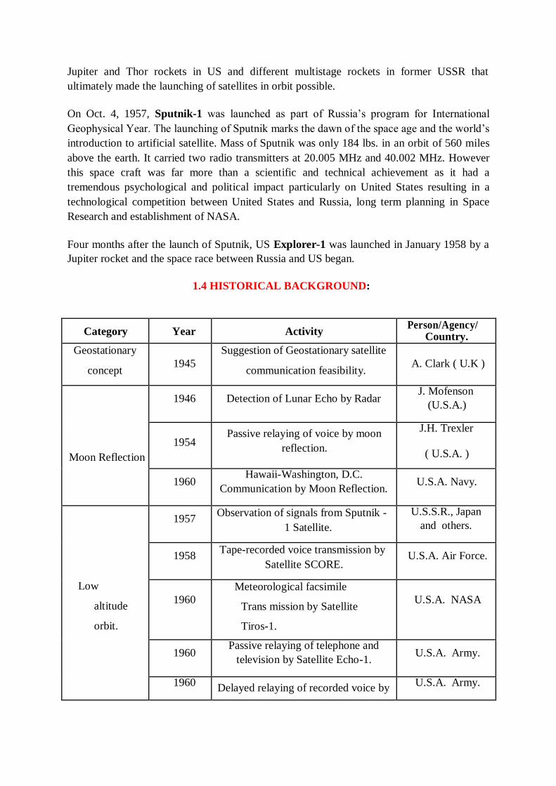
1.4 HISTORICAL BACKGROUND:
Category Year Activity Person/Agency/
Country.
Geostationary
concept
1945
Suggestion of Geostationary satellite
communication feasibility.
A. Clark ( U.K )
Moon Reflection
1946 Detection of Lunar Echo by Radar J. Mofenson
(U.S.A.)
1954 Passive relaying of voice by moon
reflection.
J.H. Trexler
( U.S.A. )
1960 Hawaii-Washington, D.C.
Communication by Moon Reflection. U.S.A. Navy.
Low
altitude
orbit.
1957 Observation of signals from Sputnik -
1 Satellite.
U.S.S.R., Japan
and others.
1958 Tape-recorded voice transmission by
Satellite SCORE. U.S.A. Air Force.
1960
Meteorological facsimile
Trans mission by Satellite
Tiros-1.
U.S.A. NASA
1960 Passive relaying of telephone and
television by Satellite Echo-1. U.S.A. Army.
1960 Delayed relaying of recorded voice by
U.S.A. Army.
Satellite Courier-1B.
1962 Active transatlantic relaying of
communication by Satellite Telstar-1.
U.S.A., U.K.,
France.
1962
Communication between manned
Satellites Vostok-3 and 4; Space
television transmission.
U.S.S.R.
1963
Scatter communication by tiny
needles in Orbit.
( West Ford Project 6 )
U.S.A. MIT.
1963 Active transpacific relaying of
communication by Satellite Relay 1.
U.S.A.
NASA,
Japan.
Synchronous
Satellite.
1963 USA-Europe-Africa communication
by Satellite Syncom 2. U.S.A. NASA
1964 Olympic Games television relaying
by Satellite Syncom 3
U.S.A., NASA
Japan.
1965 Commercial Communication (Semi-
experimental) by Satellite Early
Bird.
INTELSAT.
1.5 BASIC CONCEPTS OF SATELLITE COMMUNICATIONS
A communication satellite is an orbiting artificial earth satellite that receives a communications signal from a transmitting ground station, amplifies and possibly processes it, then transmits it back to the earth for reception by one or more receiving ground stations.
Communications information neither originates nor terminates at the satellite itself. The satellite is an active transmission relay, similar in function to relay towers used in terrestrial microwave communications.
The commercial satellite communications industry has its beginnings in the mid-
1960s, and in less than 50 years has progressed from an alternative exotic
technology to a mainstream transmission technology, which is pervasive in all
elements of the global telecommunications infrastructure. Today‘s communications
satellites offer extensive capabilities in applications involving data, voice, and
video, with services provided to fixed, broadcast, mobile, personal communications,
and private networks users.
Evolution of Satellite Communication:
During early 1950s, both passive and active satellites were considered for the purpose of communications over a large distance.
in the early years of satellite Passive satellites though successfully used communications, with the advancement in completely replaced the passive satellites.
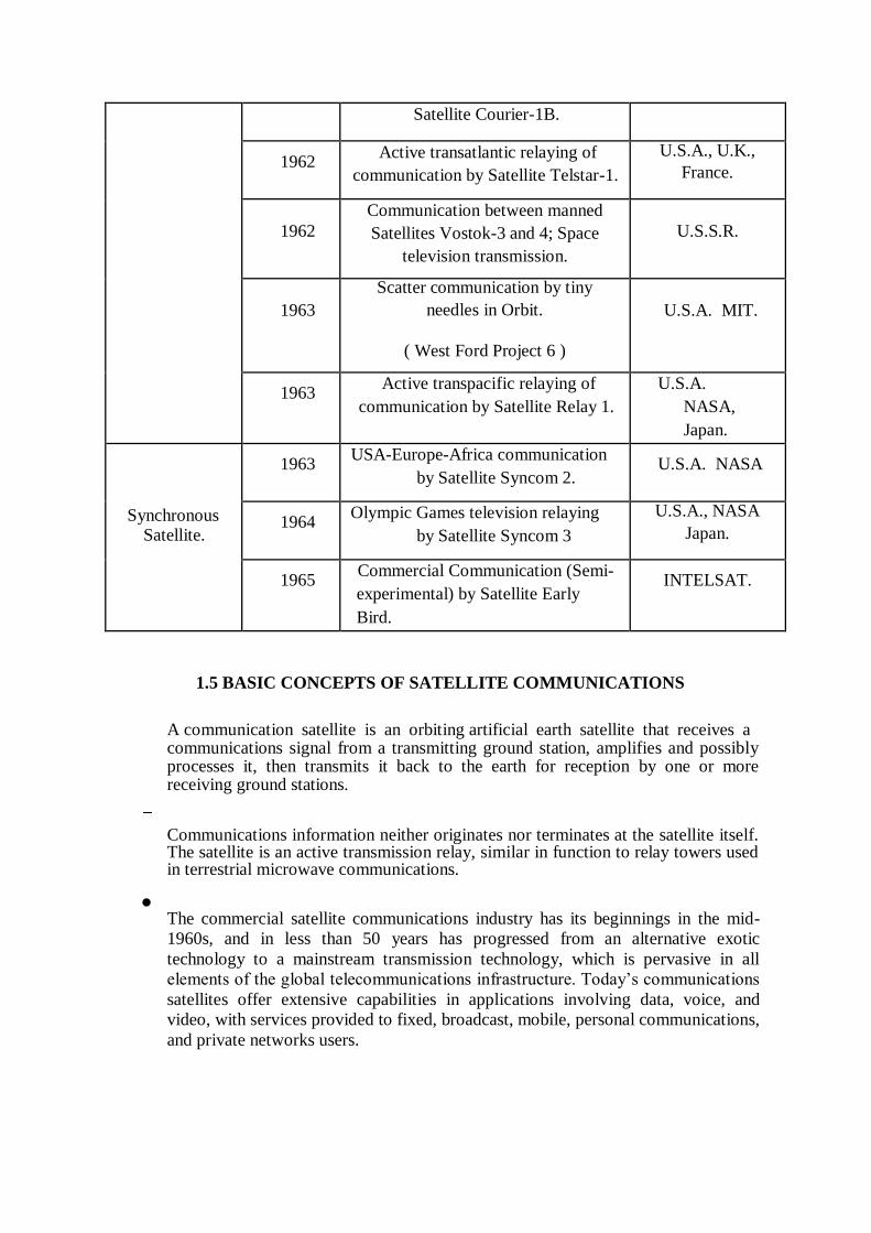
Passive Satellites:
technology active satellites have
A satellite that only reflects signals from one Earth station to another or from several Earth stations to several others.
It reflects the incident electromagnetic radiation without any modification or
amplification. It can't generate power, they simply reflect the incident power.
The first artificial passive satellite Echo-I of NASA was launched in August 1960.
Disadvantages:
Earth Stations required high power to transmit signals.
Large Earth Stations with tracking facilities were expensive.
A global system would have required a large number of passive satellites accessed randomly by different users.
Control of satellites not possible from ground.
The large attenuation of the signal while traveling the large distance between the transmitter and the receiver via the satellite was one of the most serious problems.
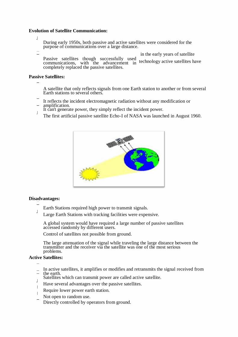
Active Satellites:
In active satellites, it amplifies or modifies and retransmits the signal received from
the earth. Satellites which can transmit power are called active satellite.
Have several advantages over the passive satellites.
Require lower power earth station.
Not open to random use.
Directly controlled by operators from ground.
Disadvantages:
Requirement of larger and powerful rockets to launch heavier satellites in orbit.
Requirement of on-board power supply.
Interruption of service due to failure of electronics components
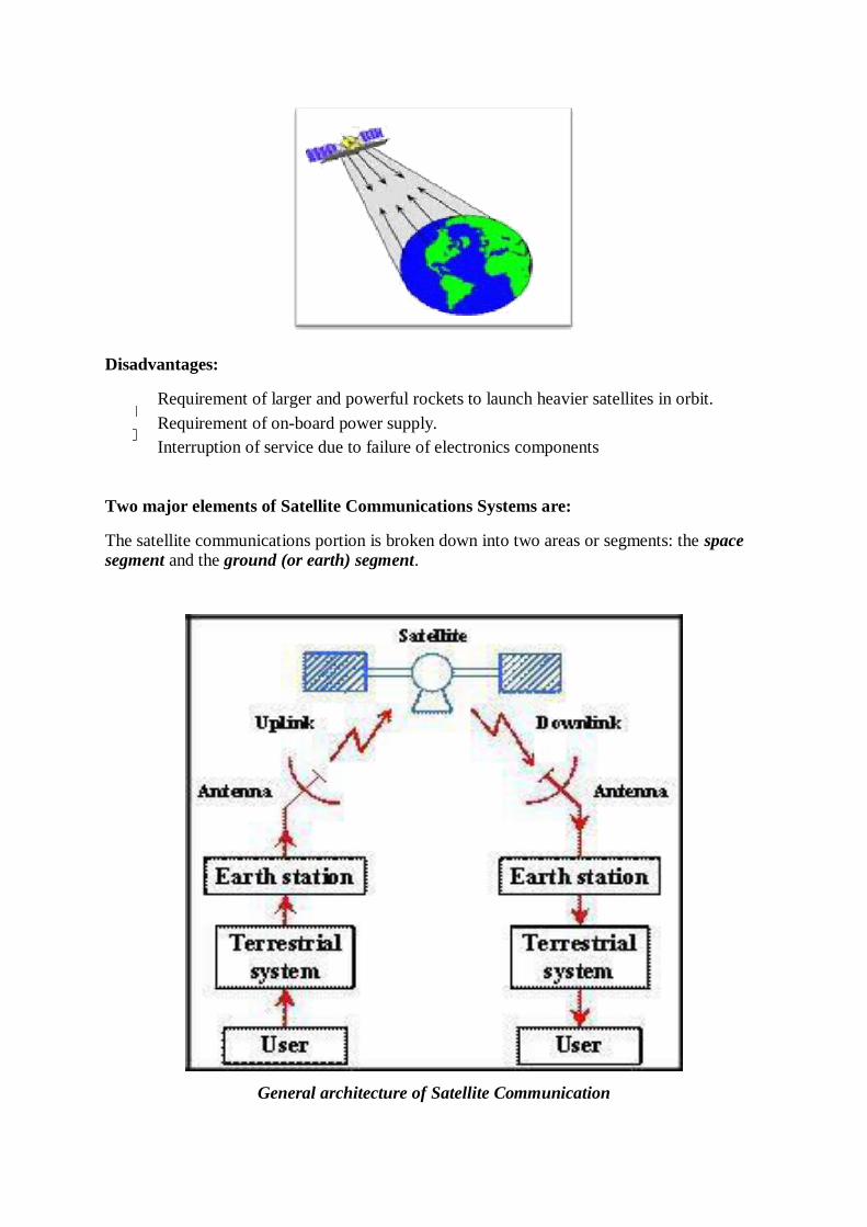
Two major elements of Satellite Communications Systems are:
The satellite communications portion is broken down into two areas or segments: the space
segment and the ground (or earth) segment.
General architecture of Satellite Communication

1.6 Space Segment:
The elements of the space segment of a communications satellite system are shown in
Figure. The space segment includes the satellite (or satellites) in orbit in the system, and the
ground station that provides the operational control of the satellite(s) in orbit. The ground
station is variously referred to as the Tracking, Telemetry, Command (TT&C) or the
Tracking, Telemetry, Command and Monitoring (TTC&M) station. The TTC&M station
provides essential spacecraft management and control functions to keep the satellite operating
safely in orbit. The TTC&M links between the spacecraft and the ground are usually separate
from the user communications links. TTC&M links may operate in the same frequency bands
or in other bands. TTC&M is most often accomplished through a separate earth terminal
facility specifically designed for the complex operations required to maintain a spacecraft in
orbit.
Ground segment:
The ground segment of the communications satellite system consists of the earth surface area
based terminals that utilize the communications capabilities of the Space Segment. TTC&M
ground stations are not included in the ground segment. The ground segment terminals
consist of three basic types:
• fixed (in-place) terminals;
• transportable terminals;
• mobile terminals.
Fixed terminals are designed to access the satellite while fixed in-place on the ground. They
may be providing different types of services, but they are defined by the fact that they are not
moving while communicating with the satellite. Examples of fixed terminals are small
terminals used in private networks (VSATs), or terminals mounted on residence buildings
used to receive broadcast satellite signals. Transportable terminals are designed to be
movable, but once on location remain fixed during transmissions to the satellite. Examples of
the transportable terminal are satellite news gathering (SGN) trucks, which move to
locations, stop in place, and then deploy an antenna to establish links to the satellite.
Mobile terminals are designed to communicate with the satellite while in motion. They are
further defined as land mobile, aeronautical mobile, or maritime mobile, depending on their
locations on or near the earth surface.
Satellite Control Centre function:
Tracking of the satellite
Receiving data
Eclipse management of satellite
Commanding the Satellite for station keeping.
Determining Orbital parameters from Tracking and Ranging data
Switching ON/OFF of different subsystems as per the operational requirements
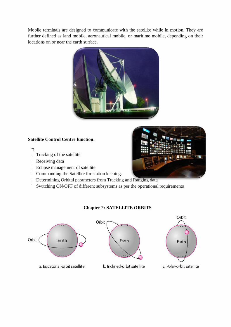
Chapter 2: SATELLITE ORBITS
Orbit: The path a Satellite follows around a planet is defined as an orbit.
Satellite Orbits are classified in two broad categories :
Non-Geostationary Orbit (NGSO)
Geo Stationary Orbit (GSO)
Early ventures with satellite communications used satellites in Non-geostationary low earth orbits due to the technical limitations of the launch vehicles in placing satellites in higher orbits.
Disadvantages of NGSO
Complex problem of transferring signal from one satellite to another.
Less expected life of satellites at NGSO.
Requires frequent replacement of satellites compared to satellite in GSO
Geo Stationary Orbit (GSO)
There is only one geostationary orbit possible around the earth
Lying on the earth‘s equatorial plane.
The satellite orbiting at the same speed as the rotational speed of the earth on its axis. Advantages:
Simple ground station tracking.
Nearly constant range
Very small frequency shift
Disadvantages:
Transmission delay of the order of 250 msec.
Large free space loss
No polar coverage
Note: A geostationary orbit is a type of geosynchronous orbit. A geosynchronous orbit can be
any orbit, like with an elliptical path, that has a period equal to the Earth‘s rotational period,
whereas a geostationary orbit has to be a circular orbit and that too placed above the equator.
Satellite orbits in terms of the orbital height:
According to distance from earth:
Geosynchronous Earth Orbit (GEO)
Medium Earth Orbit (MEO)
Low Earth Orbit (LEO)
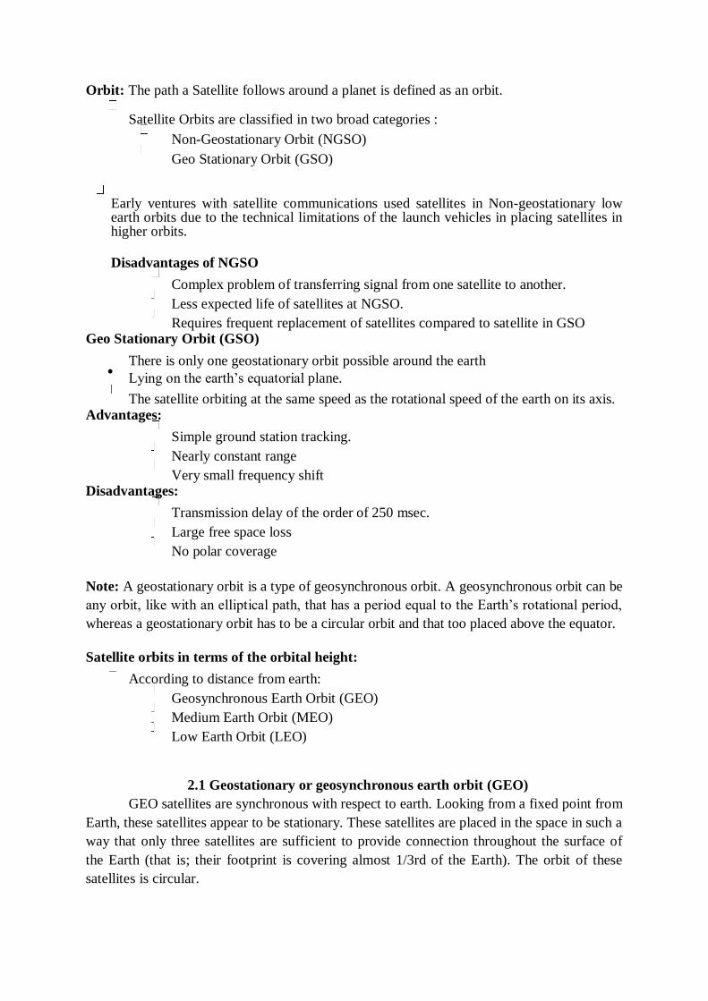
2.1 Geostationary or geosynchronous earth orbit (GEO)
GEO satellites are synchronous with respect to earth. Looking from a fixed point from
Earth, these satellites appear to be stationary. These satellites are placed in the space in such a
way that only three satellites are sufficient to provide connection throughout the surface of
the Earth (that is; their footprint is covering almost 1/3rd of the Earth). The orbit of these
satellites is circular.
There are three conditions which lead to geostationary satellites. Lifetime expectancy of these
satellites is 15 years.
1) The satellite should be placed 35,786 kms (approximated to 36,000 kms) above the surface
of the earth.
2) These satellites must travel in the rotational speed of earth, and in the direction of motion
of earth, that is eastward. 0
3) The inclination of satellite with respect to earth must be 0 .
Geostationary satellite in practical is termed as geosynchronous as there are multiple factors
which make these satellites shift from the ideal geostationary condition.
1) Gravitational pull of sun and moon makes these satellites deviate from their orbit. Over the
period of time, they go through a drag. (Earth‘s gravitational force has no effect on these
satellites due to their distance from the surface of the Earth.)
2) These satellites experience the centrifugal force due to the rotation of Earth, making them
deviate from their orbit.
3) The non-circular shape of the earth leads to continuous adjustment of speed of satellite
from the earth station.
These satellites are used for TV and radio broadcast, weather forecast and also, these
satellites are operating as backbones for the telephone networks.
Disadvantages of GEO: Northern or southern regions of the Earth (poles) have more
problems receiving these satellites due to the low elevation above a latitude of 60°, i.e., larger
antennas are needed in this case. Shading of the signals is seen in cities due to high buildings
and the low elevation further away from the equator limit transmission quality. The transmit
power needed is relatively high which causes problems for battery powered devices. These
satellites cannot be used for small mobile phones. The biggest problem for voice and also
data communication is the high latency as without having any handovers, the signal has to at
least travel 72,000 kms. Due to the large footprint, either frequencies cannot be reused or the
GEO satellite needs special antennas focusing on a smaller footprint. Transferring a GEO
into orbit is very expensive.
GEO: 35,786 km above the earth
Advantages Of GEO
Minimal Doppler shift
These factors make it ideal for satellite broadcast and other multipoint applications
GEO satellites have a 24 hour view of a particular area.
A GEO satellite‘s distance from earth gives it a large coverage area, almost a fourth of the earth‘s surface.
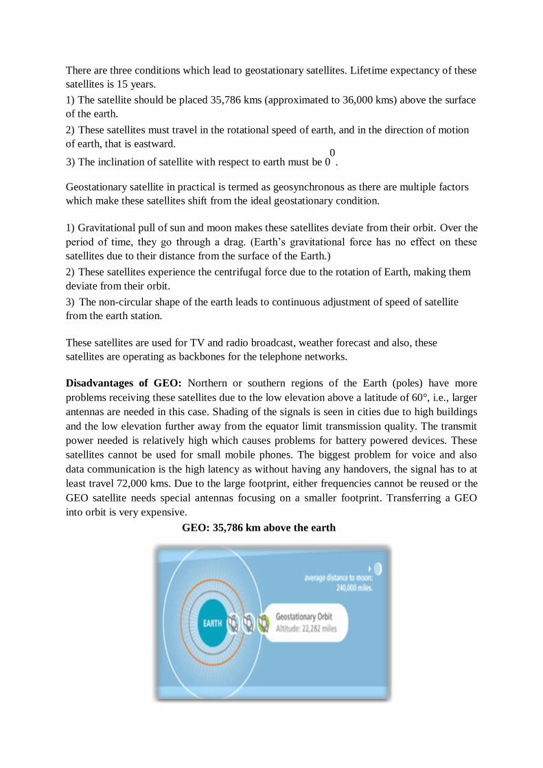
2.2 Medium Earth Orbit (MEO) satellites:
MEOs can be positioned somewhere between LEOs and GEOs, both in terms of their
orbit and due to their advantages and disadvantages. Using orbits around 20,000 km, the
system only requires a dozen satellites which is more than a GEO system, but much less than
a LEO system. These satellites move more slowly relative to the earth‘s rotation allowing a
simpler system design (satellite periods are about six hours). Depending on the inclination, a
MEO can cover larger populations, so requiring fewer handovers.
Disadvantages: Again, due to the larger distance to the earth, delay increases to about 70–80
ms. the satellites need higher transmit power and special antennas for smaller footprints.
MEO: 8,000-20,000 km above the earth
Advantages Of MEO
• A MEO satellite‘s longer duration of visibility and wider footprint means fewer
satellites are needed in a MEO network than a LEO network.
Disadvantages Of MEO
• A MEO satellite‘s distance gives it a longer time delay and weaker signal than a LEO
satellite, though not as bad as a GEO satellite.
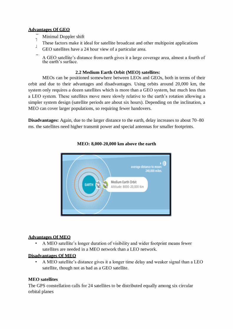
MEO satellites
The GPS constellation calls for 24 satellites to be distributed equally among six circular
orbital planes
GPS Constellation
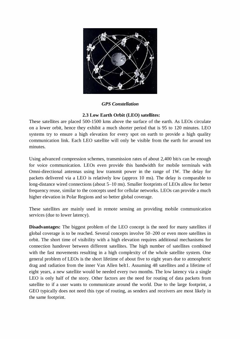
2.3 Low Earth Orbit (LEO) satellites:
These satellites are placed 500-1500 kms above the surface of the earth. As LEOs circulate
on a lower orbit, hence they exhibit a much shorter period that is 95 to 120 minutes. LEO
systems try to ensure a high elevation for every spot on earth to provide a high quality
communication link. Each LEO satellite will only be visible from the earth for around ten
minutes.
Using advanced compression schemes, transmission rates of about 2,400 bit/s can be enough
for voice communication. LEOs even provide this bandwidth for mobile terminals with
Omni-directional antennas using low transmit power in the range of 1W. The delay for
packets delivered via a LEO is relatively low (approx 10 ms). The delay is comparable to
long-distance wired connections (about 5–10 ms). Smaller footprints of LEOs allow for better
frequency reuse, similar to the concepts used for cellular networks. LEOs can provide a much
higher elevation in Polar Regions and so better global coverage.
These satellites are mainly used in remote sensing an providing mobile communication
services (due to lower latency).
Disadvantages: The biggest problem of the LEO concept is the need for many satellites if
global coverage is to be reached. Several concepts involve 50–200 or even more satellites in
orbit. The short time of visibility with a high elevation requires additional mechanisms for
connection handover between different satellites. The high number of satellites combined
with the fast movements resulting in a high complexity of the whole satellite system. One
general problem of LEOs is the short lifetime of about five to eight years due to atmospheric
drag and radiation from the inner Van Allen belt1. Assuming 48 satellites and a lifetime of
eight years, a new satellite would be needed every two months. The low latency via a single
LEO is only half of the story. Other factors are the need for routing of data packets from
satellite to if a user wants to communicate around the world. Due to the large footprint, a
GEO typically does not need this type of routing, as senders and receivers are most likely in
the same footprint.
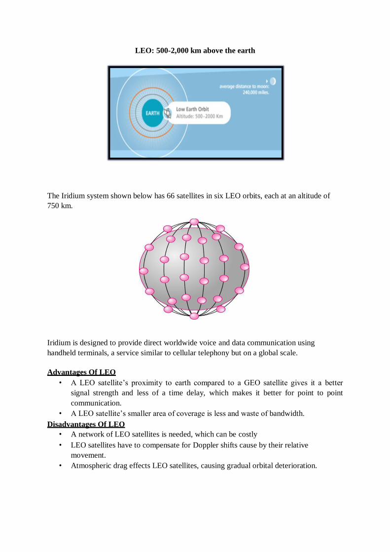
LEO: 500-2,000 km above the earth
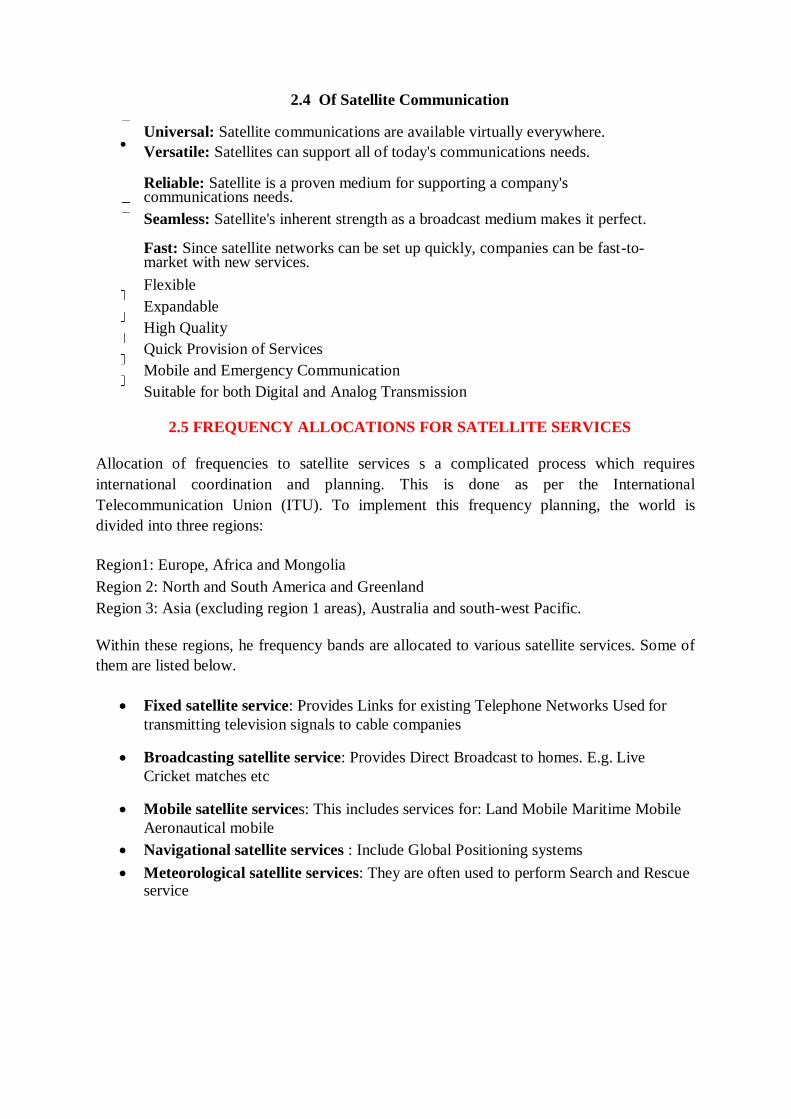
The Iridium system shown below has 66 satellites in six LEO orbits, each at an altitude of
750 km.
Iridium is designed to provide direct worldwide voice and data communication using
handheld terminals, a service similar to cellular telephony but on a global scale.
Advantages Of LEO
• A LEO satellite‘s proximity to earth compared to a GEO satellite gives it a better
signal strength and less of a time delay, which makes it better for point to point
communication.
• A LEO satellite‘s smaller area of coverage is less and waste of bandwidth.
Disadvantages Of LEO
• A network of LEO satellites is needed, which can be costly
• LEO satellites have to compensate for Doppler shifts cause by their relative
movement.
• Atmospheric drag effects LEO satellites, causing gradual orbital deterioration.
2.4 Of Satellite Communication
Universal: Satellite communications are available virtually everywhere.
Versatile: Satellites can support all of today's communications needs.
Reliable: Satellite is a proven medium for supporting a company's communications needs.
Seamless: Satellite's inherent strength as a broadcast medium makes it perfect.
Fast: Since satellite networks can be set up quickly, companies can be fast-to-market with new services.
Flexible
Expandable
High Quality
Quick Provision of Services
Mobile and Emergency Communication
Suitable for both Digital and Analog Transmission
2.5 FREQUENCY ALLOCATIONS FOR SATELLITE SERVICES
Allocation of frequencies to satellite services s a complicated process which requires
international coordination and planning. This is done as per the International
Telecommunication Union (ITU). To implement this frequency planning, the world is
divided into three regions:
Region1: Europe, Africa and Mongolia
Region 2: North and South America and Greenland
Region 3: Asia (excluding region 1 areas), Australia and south-west Pacific.
Within these regions, he frequency bands are allocated to various satellite services. Some of
them are listed below.
Fixed satellite service: Provides Links for existing Telephone Networks Used for
transmitting television signals to cable companies
Broadcasting satellite service: Provides Direct Broadcast to homes. E.g. Live
Cricket matches etc
Mobile satellite services: This includes services for: Land Mobile Maritime Mobile
Aeronautical mobile
Navigational satellite services : Include Global Positioning systems
Meteorological satellite services: They are often used to perform Search and Rescue service
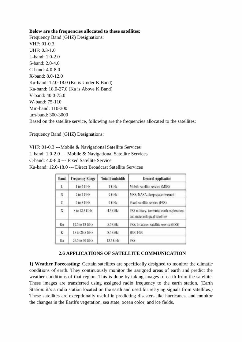
Below are the frequencies allocated to these satellites:
Frequency Band (GHZ) Designations:
VHF: 01-0.3
UHF: 0.3-1.0
L-band: 1.0-2.0
S-band: 2.0-4.0
C-band: 4.0-8.0
X-band: 8.0-12.0
Ku-band: 12.0-18.0 (Ku is Under K Band)
Ka-band: 18.0-27.0 (Ka is Above K Band)
V-band: 40.0-75.0
W-band: 75-110
Mm-band: 110-300
μm-band: 300-3000
Based on the satellite service, following are the frequencies allocated to the satellites:
Frequency Band (GHZ) Designations:
VHF: 01-0.3 ---Mobile & Navigational Satellite Services
L-band: 1.0-2.0 --- Mobile & Navigational Satellite Services
C-band: 4.0-8.0 --- Fixed Satellite Service
Ku-band: 12.0-18.0 --- Direct Broadcast Satellite Services
2.6 APPLICATIONS OF SATELLITE COMMUNICATION
1) Weather Forecasting: Certain satellites are specifically designed to monitor the climatic
conditions of earth. They continuously monitor the assigned areas of earth and predict the
weather conditions of that region. This is done by taking images of earth from the satellite.
These images are transferred using assigned radio frequency to the earth station. (Earth
Station: it‘s a radio station located on the earth and used for relaying signals from satellites.)
These satellites are exceptionally useful in predicting disasters like hurricanes, and monitor
the changes in the Earth's vegetation, sea state, ocean color, and ice fields.
2) Radio and TV Broadcast: These dedicated satellites are responsible for making 100s of
channels across the globe available for everyone. They are also responsible for broadcasting
live matches, news, world-wide radio services. These satellites require a 30-40 cm sized dish
to make these channels available globally.
3) Military Satellites: These satellites are often used for gathering intelligence, as a
communications satellite used for military purposes, or as a military weapon. A satellite by
itself is neither military nor civil. It is the kind of payload it carries that enables one to arrive
at a decision regarding its military or civilian character.
4) Navigation Satellites: The system allows for precise localization world-wide, and with
some additional techniques, the precision is in the range of some meters. Ships and aircraft
rely on GPS as an addition to traditional navigation systems. Many vehicles come with
installed GPS receivers. This system is also used, e.g., for fleet management of trucks or for
vehicle localization in case of theft.
5) Global Telephone: One of the first applications of satellites for communication was the
establishment of international telephone backbones. Instead of using cables it was sometimes
faster to launch a new satellite. But, fiber optic cables are still replacing satellite
communication across long distance as in fiber optic cable, light is used instead of radio
frequency, hence making the communication much faster (and of course, reducing the delay
caused due to the amount of distance a signal needs to travel before reaching the destination.).
Using satellites, to typically reach a distance approximately 10,000 kms away, the signal
needs to travel almost 72,000 kms, that is, sending data from ground to satellite and (mostly)
from satellite to another location on earth. This cause‘s substantial amount of delay and this
delay becomes more prominent for users during voice calls.
6) Connecting Remote Areas: Due to their geographical location many places all over the
world do not have direct wired connection to the telephone network or the internet (e.g.,
researchers on Antarctica) or because of the current state of the infrastructure of a country.
Here the satellite provides a complete coverage and (generally) there is one satellite always
present across a horizon.
7) Global Mobile Communication: The basic purpose of satellites for mobile
communication is to extend the area of coverage. Cellular phone systems, such as AMPS and
GSM (and their successors) do not cover all parts of a country. Areas that are not covered
usually have low population where it is too expensive to install a base station. With the
integration of satellite communication, however, the mobile phone can switch to satellites
offering world-wide connectivity to a customer. Satellites cover a certain area on the earth.
This area is termed as a „footprint‟ of that satellite. Within the footprint, communication with
that satellite is possible for mobile users. These users communicate using a Mobile-User-Link
(MUL). The base-stations communicate with satellites using a Gateway-Link (GWL).
Sometimes it becomes necessary for satellite to create a communication link between users
belonging to two different footprints. Here the satellites send signals to each other and this is
done using Inter-Satellite-Link (ISL).
2.7 FUTURE OF SATELLITE COMMUNICATIONS
Future communication satellites will have
• More onboard processing capabilities,
• More power, and
• Larger-aperture antennas that will enable satellites to handle more bandwidth.
• The demand for more bandwidth will ensure the long-term viability of the
commercial satellite industry well into the 21st century.
Conclusion:
By going through the above slides we came to know that satellite is mostly responsible for:
Telecommunication transmission
Reception of television signals
Whether forecasting
Which are very important in our daily life.
Nm /kg .
Chapter 3:ORBITAL MECHANICS AND LAUNCHERS
3.1 ORBITAL MECHANICS
To achieve a stable orbit around the earth, a spacecraft must first be beyond the bulk of the earth‘s atmosphere, i.e., in what is popularly called space.
According to Newton's law of motion F=ma. Where a = acceleration, F= force acting on the object and m= mass of the object. It helps us understand the motion of satellite in a stable orbit.(neglecting any drag or other perturbing forces).
(F=ma) states that the force acting on a body is equal to the mass of the body multiplied by the resulting acceleration of the body.
Thus, for a given force, the lighter the mass of the body, the higher the acceleration will be.
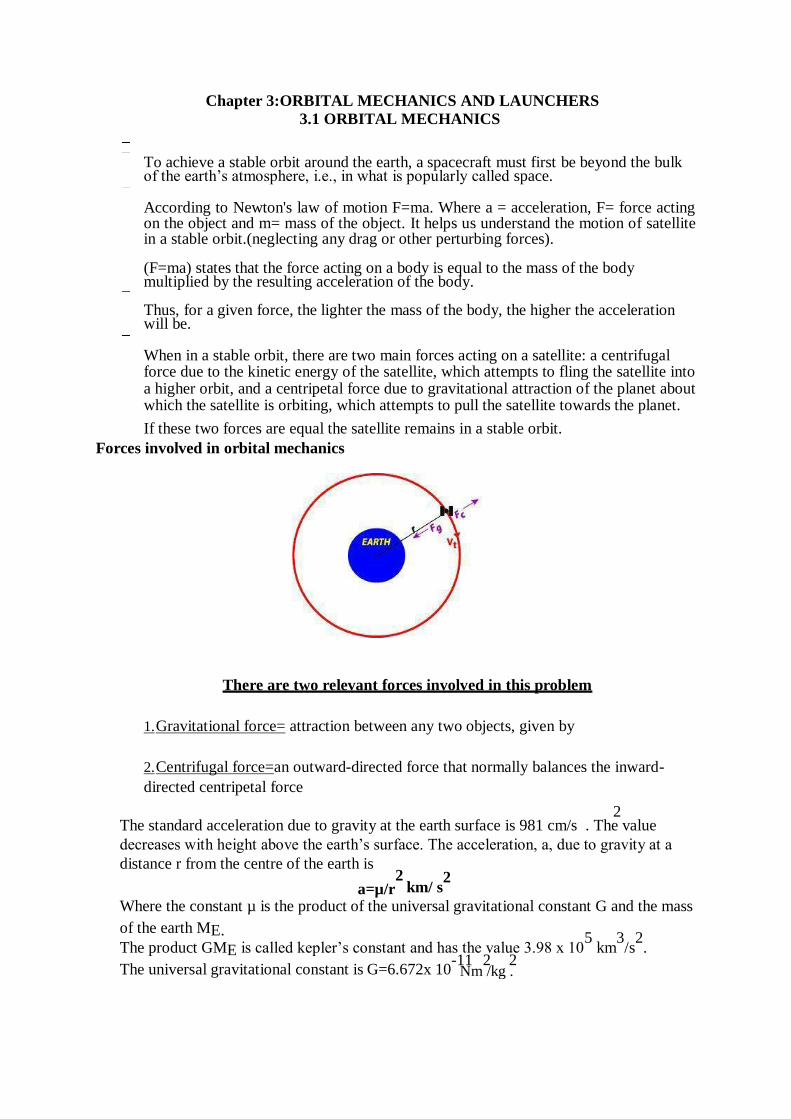
When in a stable orbit, there are two main forces acting on a satellite: a centrifugal force due to the kinetic energy of the satellite, which attempts to fling the satellite into a higher orbit, and a centripetal force due to gravitational attraction of the planet about which the satellite is orbiting, which attempts to pull the satellite towards the planet.
If these two forces are equal the satellite remains in a stable orbit.
Forces involved in orbital mechanics
There are two relevant forces involved in this problem
1. Gravitational force= attraction between any two objects, given by
2. Centrifugal force=an outward-directed force that normally balances the inward-
directed centripetal force
2 The standard acceleration due to gravity at the earth surface is 981 cm/s . The value
decreases with height above the earth‘s surface. The acceleration, a, due to gravity at a
distance r from the centre of the earth is 2
a=µ/r km/ s2
Where the constant µ is the product of the universal gravitational constant G and the mass
of the earth ME.
The product GME is called kepler‘s constant and has the value 3.98 x 10⁵
km3/s
2.
The universal gravitational constant is G=6.672x 10⁻¹¹ 2 2
The mass of the earth ME =5.97 x 1024
kg.
Since fore= mass x acceleration, the centripetal force acting on the satellite, Fin is given by 2
Fin= m x (µ/r ) 2
=m x (G ME /r )
In a similar fashion, the centrifugal acceleration is given by
a=v2
/r
Which will give the centrifugal force, Fout as
Fout=m
x(v2
If the forces of the satellite are balanced Fin=Fout 2
/r )
2
m x (µ/r )=m x(v /r ) Hence the velocity v of the satellite in a circular orbit is given by
1/2 v=(µ/r)
If the orbit is circular, the distance traveled by a satellite in one orbit around a planet is 2∏r ,
where r is the radius of the orbit from the satellite to the center of the planet. Since distance
divided by velocity equals time to travel the distance, the period of satellite‘s orbit, T, will be
T= (2∏r )/v = (2∏r )/[(µ/r)1/2
T=(2∏r 3/2
1/2
) Using standard mathematical procedures we can develop an equation for the radius of the
satellite‘s orbit, r, namely
3.2 Kepler’s Laws
Kepler‘s laws of planetary motion apply to any two bodies in space that interact through gravitation. The laws of motion are described through three fundamental principles.
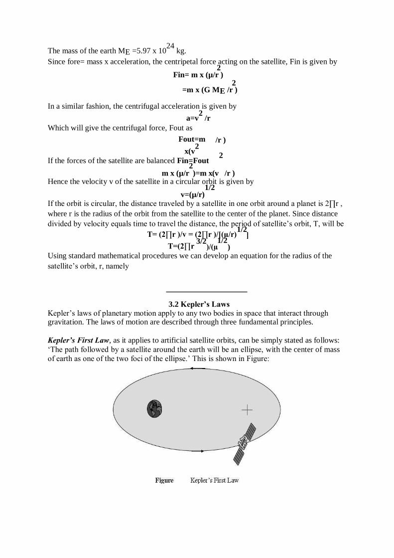
Kepler’s First Law, as it applies to artificial satellite orbits, can be simply stated as follows:
‗The path followed by a satellite around the earth will be an ellipse, with the center of mass
of earth as one of the two foci of the ellipse.‘ This is shown in Figure:
If no other forces are acting on the satellite, either intentionally by orbit control or unintentionally as in gravity forces from other bodies, the satellite will eventually settle in an elliptical orbit, with the earth as one of the foci of the ellipse. The ‗size‘ of the ellipse will
depend on satellite mass and its angular velocity.
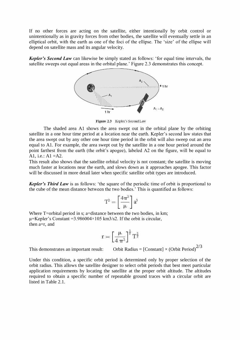
Kepler’s Second Law can likewise be simply stated as follows: ‗for equal time intervals, the satellite sweeps out equal areas in the orbital plane.‘ Figure 2.3 demonstrates this concept.
The shaded area A1 shows the area swept out in the orbital plane by the orbiting satellite in a one hour time period at a location near the earth. Kepler‘s second law states that
the area swept out by any other one hour time period in the orbit will also sweep out an area
equal to A1. For example, the area swept out by the satellite in a one hour period around the
point farthest from the earth (the orbit‘s apogee), labeled A2 on the figure, will be equal to A1, i.e.: A1 =A2.
This result also shows that the satellite orbital velocity is not constant; the satellite is moving
much faster at locations near the earth, and slows down as it approaches apogee. This factor
will be discussed in more detail later when specific satellite orbit types are introduced.
Kepler’s Third Law is as follows: ‗the square of the periodic time of orbit is proportional to the cube of the mean distance between the two bodies.‘ This is quantified as follows:
Where T=orbital period in s; a=distance between the two bodies, in km; µ=Kepler‘s Constant =3.986004×10⁵ km3/s2. If the orbit is circular,
then a=r, and
This demonstrates an important result: Orbit Radius = [Constant] × (Orbit Period)2/3
Under this condition, a specific orbit period is determined only by proper selection of the
orbit radius. This allows the satellite designer to select orbit periods that best meet particular
application requirements by locating the satellite at the proper orbit altitude. The altitudes required to obtain a specific number of repeatable ground traces with a circular orbit are
listed in Table 2.1.
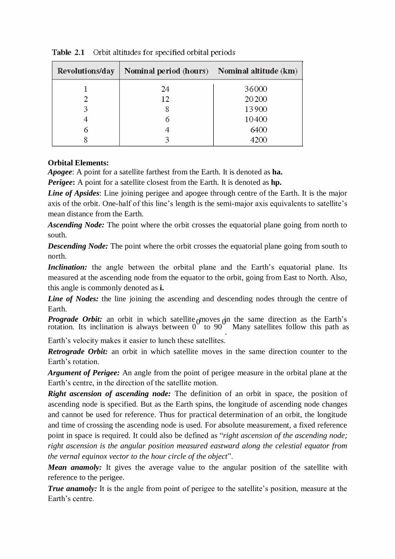
Orbital Elements:
Apogee: A point for a satellite farthest from the Earth. It is denoted as ha.
Perigee: A point for a satellite closest from the Earth. It is denoted as hp.
Line of Apsides: Line joining perigee and apogee through centre of the Earth. It is the major
axis of the orbit. One-half of this line‘s length is the semi-major axis equivalents to satellite‘s
mean distance from the Earth.
Ascending Node: The point where the orbit crosses the equatorial plane going from north to
south.
Descending Node: The point where the orbit crosses the equatorial plane going from south to
north.
Inclination: the angle between the orbital plane and the Earth‘s equatorial plane. Its
measured at the ascending node from the equator to the orbit, going from East to North. Also,
this angle is commonly denoted as i.
Line of Nodes: the line joining the ascending and descending nodes through the centre of
Earth.
Prograde Orbit: an orbit in which satellite moves in the same direction as the Earth‘s rotation. Its inclination is always between 0
0 to 90
0 Many satellites follow this path as
. Earth‘s velocity makes it easier to lunch these satellites.
Retrograde Orbit: an orbit in which satellite moves in the same direction counter to the
Earth‘s rotation.
Argument of Perigee: An angle from the point of perigee measure in the orbital plane at the
Earth‘s centre, in the direction of the satellite motion.
Right ascension of ascending node: The definition of an orbit in space, the position of
ascending node is specified. But as the Earth spins, the longitude of ascending node changes
and cannot be used for reference. Thus for practical determination of an orbit, the longitude
and time of crossing the ascending node is used. For absolute measurement, a fixed reference
point in space is required. It could also be defined as ―right ascension of the ascending node;
right ascension is the angular position measured eastward along the celestial equator from
the vernal equinox vector to the hour circle of the object‖.
Mean anamoly: It gives the average value to the angular position of the satellite with
reference to the perigee.
True anamoly: It is the angle from point of perigee to the satellite‘s position, measure at the
Earth‘s centre.
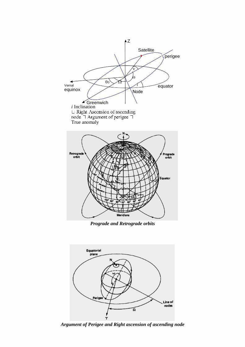
i Inclination
True anomaly
Prograde and Retrograde orbits
Argument of Perigee and Right ascension of ascending node
Z
Satellite
perigee
0
Vernal
equinox
equator
Greenwich
Orbital Elements Following are the 6 elements of the Keplerian Element set commonly
known as orbital elements.
Semi-Major axis (a)
Eccentricity (e)
They give the shape (of ellipse) to the satellite‘s orbit.
3. Mean anomaly (M0)
It denotes the position of a satellite in its orbit at a given reference time.
4. Argument of Perigee
It gives the rotation of the orbit‘s perigee point relative to the orbit‟s nodes in the earth‟s
equatorial plane.
Inclination
Right ascension of ascending node
They relate the orbital plane‘s position to the Earth. As the equatorial bulge causes a slow
variation in argument of perigee and right ascension of ascending node, and because other
perturbing forces may alter the orbital elements slightly, the values are specified for the
reference time or epoch.
3.3 LOOK ANGLE DETERMINATION
The look angles for the ground station antenna are Azimuth and Elevation angles. They are
required at the antenna so that it points directly at the satellite. Look angles are calculated by
considering the elliptical orbit. These angles change in order to track the satellite.
For geostationary orbit, these angels values does not change as the satellites are stationary
with respect to earth. Thus large earth stations are used for commercial communications,
these antennas beamwidth is very narrow and the tracking mechanism is required to
compensate for the movement of the satellite about the nominal geostationary position.
For home antennas, antenna beamwidth is quite broad and hence no tracking is essential. This
leads to a fixed position for these antennas.
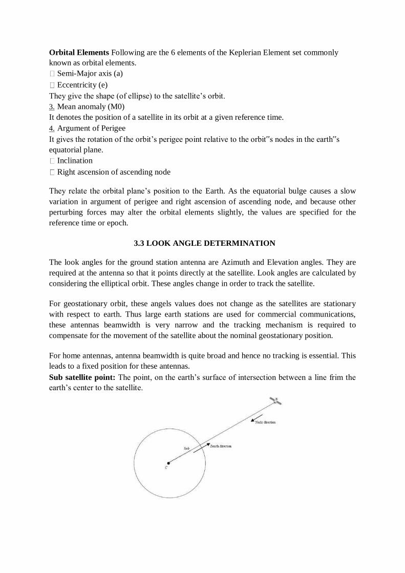
Sub satellite point: The point, on the earth‘s surface of intersection between a line frim the
earth‘s center to the satellite.
The following information is needed to determine the look angles of geostationary orbit.
Earth Station Latitude
Earth Station Longitude
Sub-Satellite Point‘s Longitude
ES: Position of Earth Station
SS: Sub-Satellite Point
S: Satellite
Range from ES to S
Angle to be determined
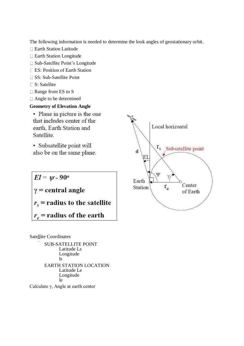
Geometry of Elevation Angle
Satellite Coordinates
SUB-SATELLITE POINT Latitude Ls Longitude ls
EARTH STATION LOCATION
Latitude Le Longitude le
Calculate γ, Angle at earth center
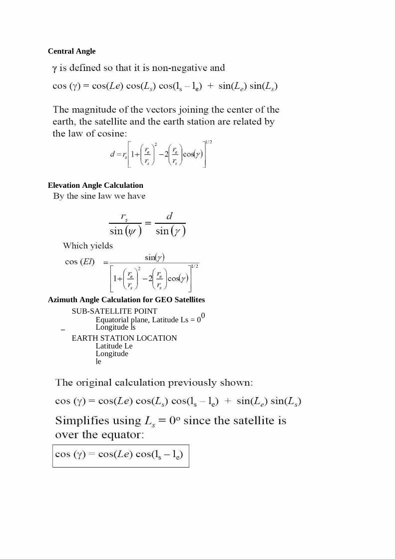
Central Angle
Elevation Angle Calculation
Azimuth Angle Calculation for GEO Satellites
SUB-SATELLITE POINT
Equatorial plane, Latitude Ls = 00
Longitude ls
EARTH STATION LOCATION Latitude Le Longitude le
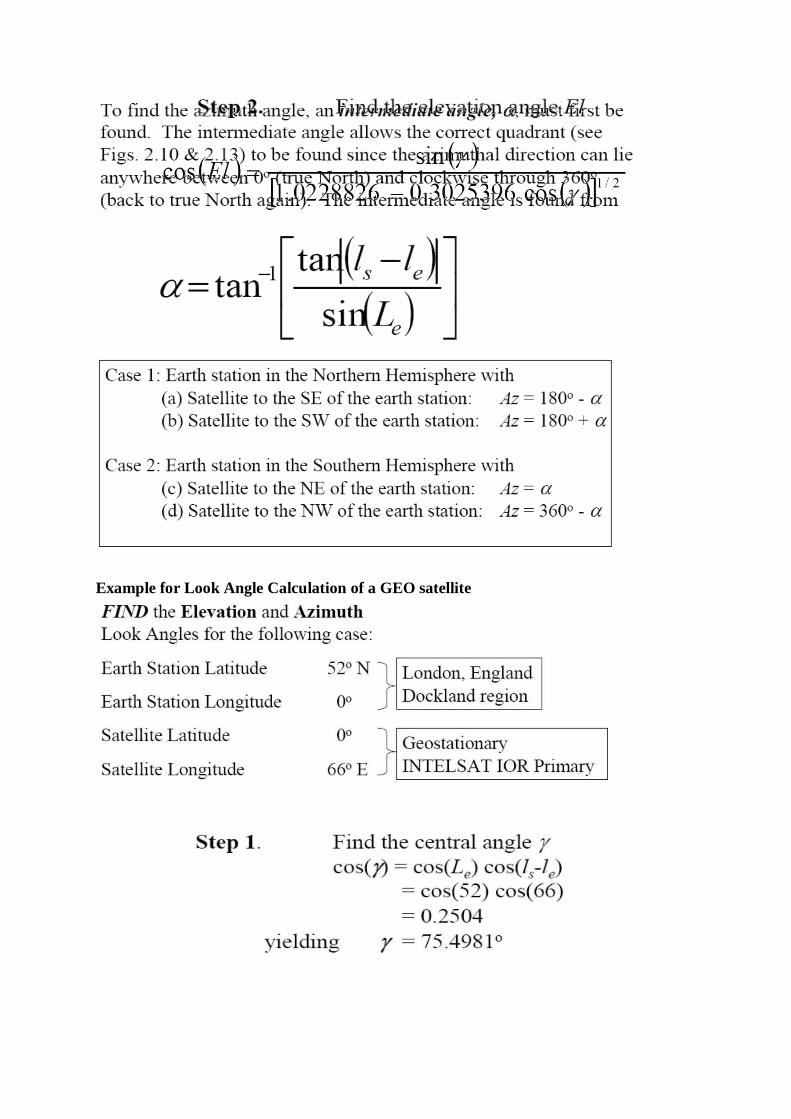
Example for Look Angle Calculation of a GEO satellite
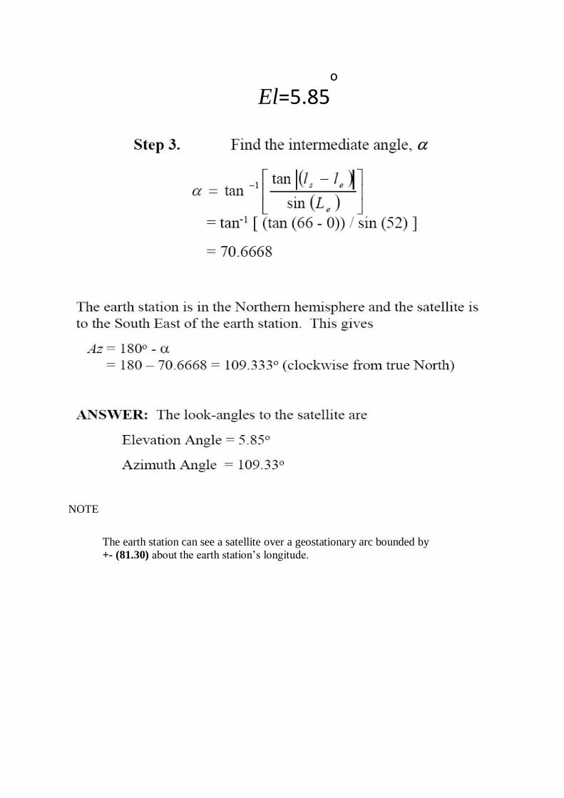
NOTE
The earth station can see a satellite over a geostationary arc bounded by
+- (81.30) about the earth station‘s longitude.
El=5.85
3.4 ORBITAL PERTURBATIONS
Theoretically, an orbit described by Kepler is ideal as Earth is considered to be a perfect sphere and the force acting around the Earth is the centrifugal force. This force is supposed to balance the gravitational pull of the earth.
In reality, other forces also play an important role and affect the motion of the satellite. These forces are the gravitational forces of Sun and Moon along with the atmospheric drag.
Effect of Sun and Moon is more pronounced on geostationary earth satellites where as the atmospheric drag effect is more pronounced for low earth orbit satellites.
As the shape of Earth is not a perfect sphere, it causes some variations in the path followed by the satellites around the primary. As the Earth is bulging from the equatorial belt, and keeping in mind that an orbit is not a physical entity, and it is the forces resulting from an oblate Earth which act on the satellite produce a change in the orbital parameters.
This causes the satellite to drift as a result of regression of the nodes and the latitude of the point of perigee (point closest to the Earth). This leads to rotation of the line of apsides. As the orbit itself is moving with respect to the Earth, the resultant changes are seen in the values of argument of perigee and right ascension of ascending node.
Due to the non-spherical shape of Earth, one more effect called as the ―Satellite Graveyard‖ is seen. The non-spherical shape leads to the small value of eccentricity at the equatorial plane. This causes a gravity gradient on GEO satellite and makes them drift to one of the two stable points which coincide with minor axis of the equatorial ellipse.
Working satellites are made to drift back to their position but out-of-service satellites are eventually drifted to these points, and making that point a Satellite Graveyard.
Atmospheric Drag
For Low Earth orbiting satellites, the effect of atmospheric drag is more pronounces. The impact of this drag is maximum at the point of perigee. Drag (pull towards the Earth) has an effect on velocity of Satellite (velocity reduces).
This causes the satellite to not reach the apogee height successive revolutions. This leads to a change in value of semi-major axis and eccentricity. Satellites in service are maneuvered by the earth station back to their original orbital position.
3.5 ORBIT DETERMINATION
Orbit determination requires that sufficient measurements be made to determine uniquely the
six orbital elements needed to calculate the future of the satellite, and hence calculate the
required changes that need to be made to the orbit to keep it within the nominal orbital
location. The control earth stations used to measure the angular position of the satellites also
carryout range measurements using unique time stamps in the telemetry stream or
communication carrier. These earth stations generally referred to as the TTC&M(telemetry
tracking command and monitoring) stations of the satellite network.
3.6 LAUNCHES AND LAUNCH VEHICLES
A satellite cannot be placed into a stable orbit unless two parameters that are uniquely
coupled together the velocity vector and the orbital height are simultaneously correct. There
is little point in orbiting the correct height and not having the appropriate velocity component
in the correct direction to achieve the desired orbit. A geostationary satellite for example
must be in an orbit at height 35,786.03km above the surface of the earth with an inclination
of zero degrees an ellipticity of zero, and a velocity of 3074.7m/s tangential to the earth in the
plane of the orbit, which is the earths equatorial plane. The further out from the earth the orbit
is greater the energy required from the launch vehicle to reach that orbit. In any earth satellite
launch, the largest fraction of the energy expanded by the rocket is used to accelerate the
vehicle from rest until it is about 20miles (32 km) above the earth.
To make the most efficient use of the fuel, it is common to shed excess mass from the
launcher as it moves upward on launch; this is called staging.
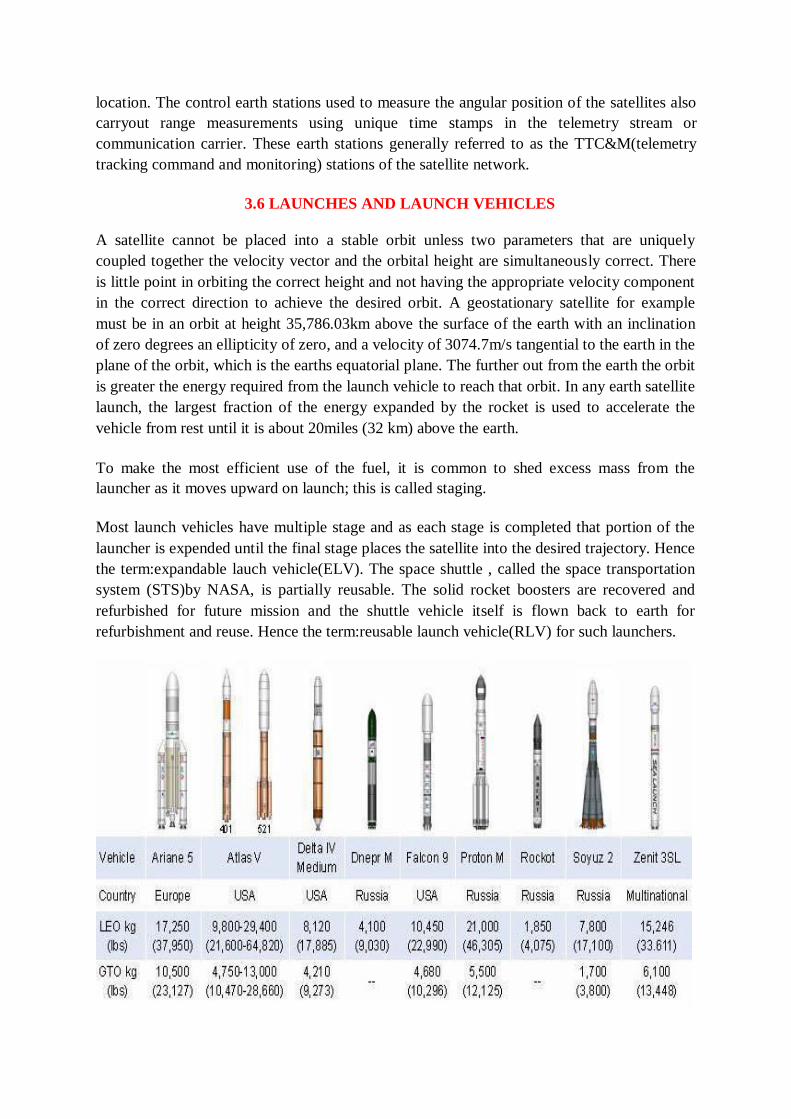
Most launch vehicles have multiple stage and as each stage is completed that portion of the
launcher is expended until the final stage places the satellite into the desired trajectory. Hence
the term:expandable lauch vehicle(ELV). The space shuttle , called the space transportation
system (STS)by NASA, is partially reusable. The solid rocket boosters are recovered and
refurbished for future mission and the shuttle vehicle itself is flown back to earth for
refurbishment and reuse. Hence the term:reusable launch vehicle(RLV) for such launchers.
Launch vehicle selection factor
Price/cost
Reliability-Recent launch success/failure history
Dependable launch schedule- Urgency of the customer
Performance
Spacecraft fit
Safety issues
Launch site location
Availability-launch site; vehicle; schedule;
Market conditions-what the market will bear
3.7 LAUNCHING ORBITS
Low Earth Orbiting satellites are directly injected into their orbits. This cannot be done incase
of GEOs as they have to be positioned 36,000kms above the Earth‟s surface. Launch vehicles
are hence used to set these satellites in their orbits. These vehicles are reusable. They are also known as „Space Transportation System‟ (STS).
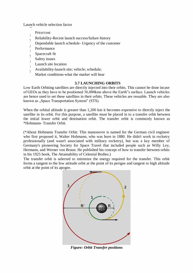
When the orbital altitude is greater than 1,200 km it becomes expensive to directly inject the
satellite in its orbit. For this purpose, a satellite must be placed in to a transfer orbit between the initial lower orbit and destination orbit. The transfer orbit is commonly known as
*Hohmann- Transfer Orbit.
(*About Hohmann Transfer Orbit: This manoeuvre is named for the German civil engineer
who first proposed it, Walter Hohmann, who was born in 1880. He didn't work in rocketry professionally (and wasn't associated with military rocketry), but was a key member of
Germany's pioneering Society for Space Travel that included people such as Willy Ley,
Hermann, and Werner von Braun. He published his concept of how to transfer between orbits
in his 1925 book, The Attainability of Celestial Bodies.)
The transfer orbit is selected to minimize the energy required for the transfer. This orbit forms a tangent to the low attitude orbit at the point of its perigee and tangent to high altitude orbit at the point of its apogee.
Figure: Orbit Transfer positions
The rocket injects the satellite with the required thrust** into the transfer orbit. With the STS,
the satellite carries a perigee kick motor*** which imparts the required thrust to inject the
satellite in its transfer orbit. Similarly, an apogee kick motor (AKM) is used to inject the
satellite in its destination orbit.
Generally it takes 1-2 months for the satellite to become fully functional. The Earth Station
performs the Telemetry Tracking and Command**** function to control the satellite transits
and functionalities.
(**Thrust: It is a reaction force described quantitatively by Newton's second and third laws.
When a system expels or accelerates mass in one direction the accelerated mass will cause a
force of equal magnitude but opposite direction on that system.)
(***Kick Motor refers to a rocket motor that is regularly employed on artificial satellites
destined for a geostationary orbit. As the vast majority of geostationary satellite launches are
carried out from spaceports at a significant distance away from Earth's equator, the carrier
rocket would only be able to launch the satellite into an elliptical orbit of maximum apogee
35,784-kilometres and with a non-zero inclination approximately equal to the latitude of the
launch site.) (****TT&C: it‟s a sub-system where the functions performed by the satellite
control network to maintain health and status, measure specific mission parameters and
processing over time a sequence of these measurement to refine parameter knowledge, and
transmit mission commands to the satellite. Detailed study of TT&C in the upcoming units.)
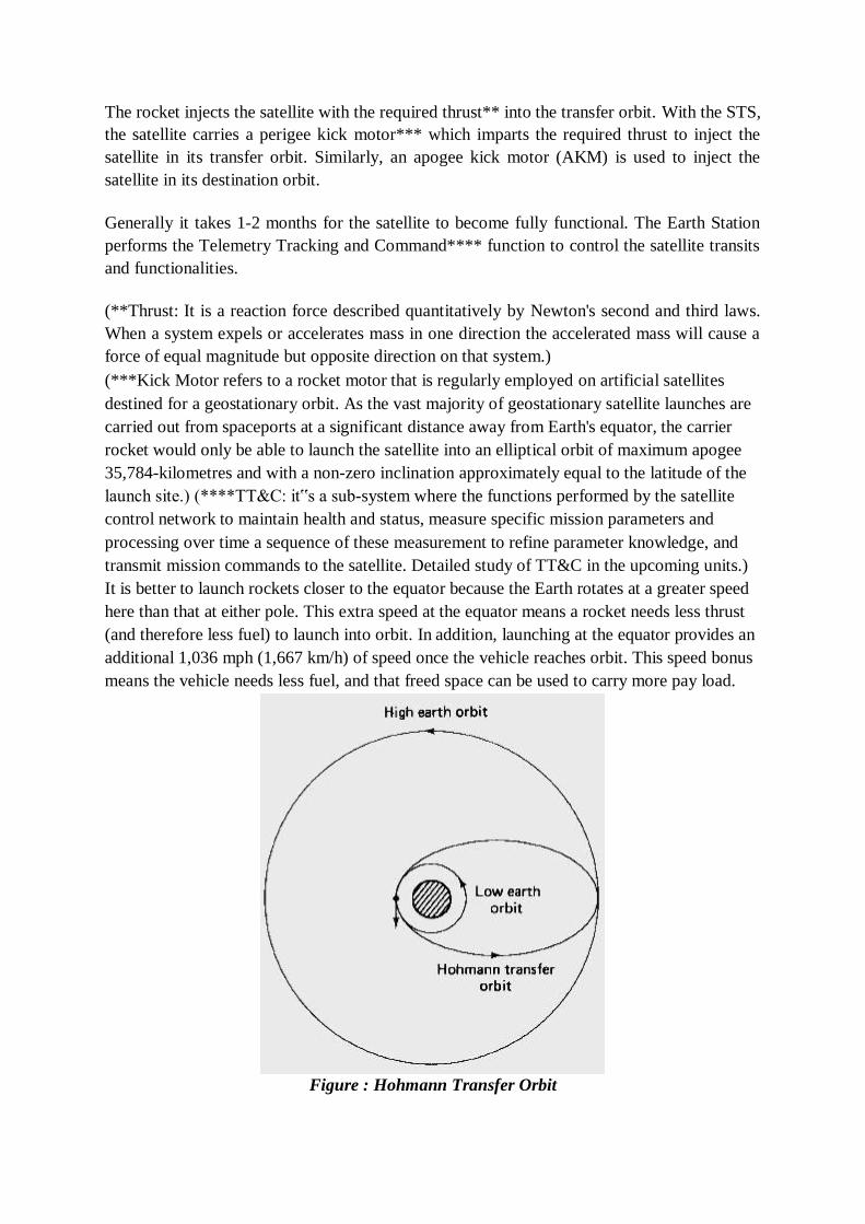
It is better to launch rockets closer to the equator because the Earth rotates at a greater speed
here than that at either pole. This extra speed at the equator means a rocket needs less thrust
(and therefore less fuel) to launch into orbit. In addition, launching at the equator provides an
additional 1,036 mph (1,667 km/h) of speed once the vehicle reaches orbit. This speed bonus
means the vehicle needs less fuel, and that freed space can be used to carry more pay load.
Figure : Hohmann Transfer Orbit
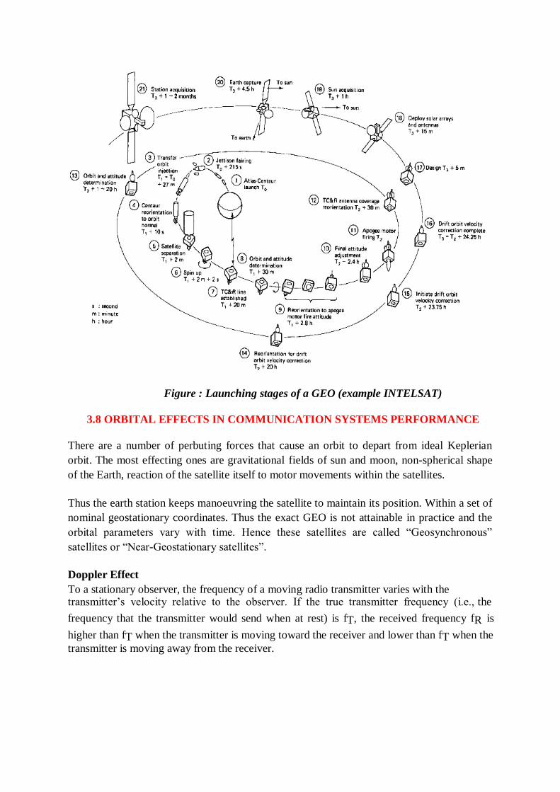
Figure : Launching stages of a GEO (example INTELSAT)
3.8 ORBITAL EFFECTS IN COMMUNICATION SYSTEMS PERFORMANCE
There are a number of perbuting forces that cause an orbit to depart from ideal Keplerian
orbit. The most effecting ones are gravitational fields of sun and moon, non-spherical shape
of the Earth, reaction of the satellite itself to motor movements within the satellites.
Thus the earth station keeps manoeuvring the satellite to maintain its position. Within a set of
nominal geostationary coordinates. Thus the exact GEO is not attainable in practice and the
orbital parameters vary with time. Hence these satellites are called ―Geosynchronous‖
satellites or ―Near-Geostationary satellites‖.
Doppler Effect
To a stationary observer, the frequency of a moving radio transmitter varies with the transmitter‘s velocity relative to the observer. If the true transmitter frequency (i.e., the
frequency that the transmitter would send when at rest) is fT, the received frequency fR is
higher than fT when the transmitter is moving toward the receiver and lower than fT when the
transmitter is moving away from the receiver.
Range variations
Even with the best station keeping systems available for geostationary satellites, the position
of a satellite with respect to earth exhibits a cyclic daily variation. The variation in position
will lead to a variation in range between the satellite and user terminals. If time division
multiple access(TDMA) is being used, careful attention must be paid to the timing of the
frames within the TDMA bursts so that the individual user frames arrive at the satellite in the
correct sequence and at the correct time.
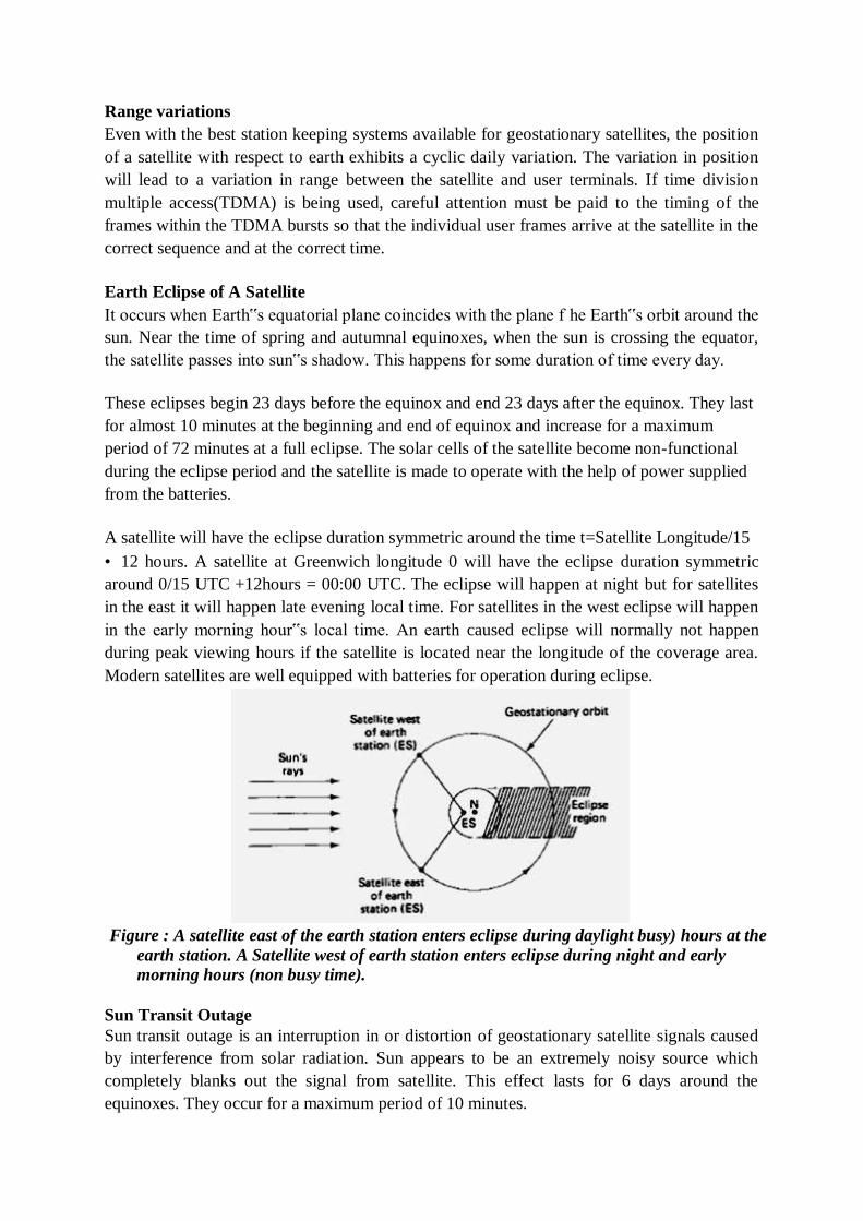
Earth Eclipse of A Satellite
It occurs when Earth‟s equatorial plane coincides with the plane f he Earth‟s orbit around the
sun. Near the time of spring and autumnal equinoxes, when the sun is crossing the equator,
the satellite passes into sun‟s shadow. This happens for some duration of time every day.
These eclipses begin 23 days before the equinox and end 23 days after the equinox. They last
for almost 10 minutes at the beginning and end of equinox and increase for a maximum
period of 72 minutes at a full eclipse. The solar cells of the satellite become non-functional
during the eclipse period and the satellite is made to operate with the help of power supplied
from the batteries.
A satellite will have the eclipse duration symmetric around the time t=Satellite Longitude/15
• 12 hours. A satellite at Greenwich longitude 0 will have the eclipse duration symmetric
around 0/15 UTC +12hours = 00:00 UTC. The eclipse will happen at night but for satellites
in the east it will happen late evening local time. For satellites in the west eclipse will happen
in the early morning hour‟s local time. An earth caused eclipse will normally not happen
during peak viewing hours if the satellite is located near the longitude of the coverage area.
Modern satellites are well equipped with batteries for operation during eclipse.
Figure : A satellite east of the earth station enters eclipse during daylight busy) hours at the
earth station. A Satellite west of earth station enters eclipse during night and early
morning hours (non busy time).
Sun Transit Outage
Sun transit outage is an interruption in or distortion of geostationary satellite signals caused
by interference from solar radiation. Sun appears to be an extremely noisy source which
completely blanks out the signal from satellite. This effect lasts for 6 days around the
equinoxes. They occur for a maximum period of 10 minutes.
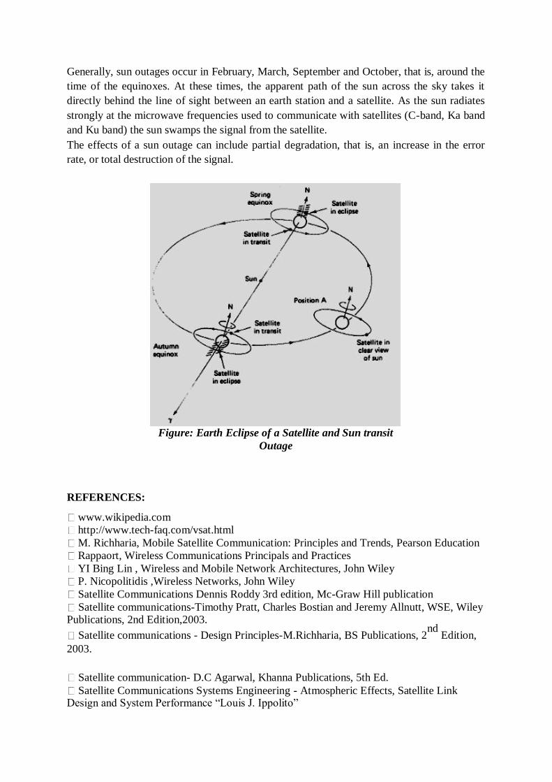
Generally, sun outages occur in February, March, September and October, that is, around the
time of the equinoxes. At these times, the apparent path of the sun across the sky takes it
directly behind the line of sight between an earth station and a satellite. As the sun radiates
strongly at the microwave frequencies used to communicate with satellites (C-band, Ka band
and Ku band) the sun swamps the signal from the satellite.
The effects of a sun outage can include partial degradation, that is, an increase in the error
rate, or total destruction of the signal.
Figure: Earth Eclipse of a Satellite and Sun transit
Outage
REFERENCES:
www.wikipedia.com
http://www.tech-faq.com/vsat.html
M. Richharia, Mobile Satellite Communication: Principles and Trends, Pearson Education
Rappaort, Wireless Communications Principals and Practices
YI Bing Lin , Wireless and Mobile Network Architectures, John Wiley
P. Nicopolitidis ,Wireless Networks, John Wiley
Satellite Communications Dennis Roddy 3rd edition, Mc-Graw Hill publication
Satellite communications-Timothy Pratt, Charles Bostian and Jeremy Allnutt, WSE, Wiley Publications, 2nd Edition,2003.
Satellite communications - Design Principles-M.Richharia, BS Publications, 2nd
Edition,
2003.
Satellite communication- D.C Agarwal, Khanna Publications, 5th Ed.
Satellite Communications Systems Engineering - Atmospheric Effects, Satellite Link Design and System Performance ―Louis J. Ippolito‖

WEBLINKS:
1. http://en.wikipedia.org/wiki/Communications_satellite#Applications
Chapter 4:SATELLITE SUBSYSTEMS
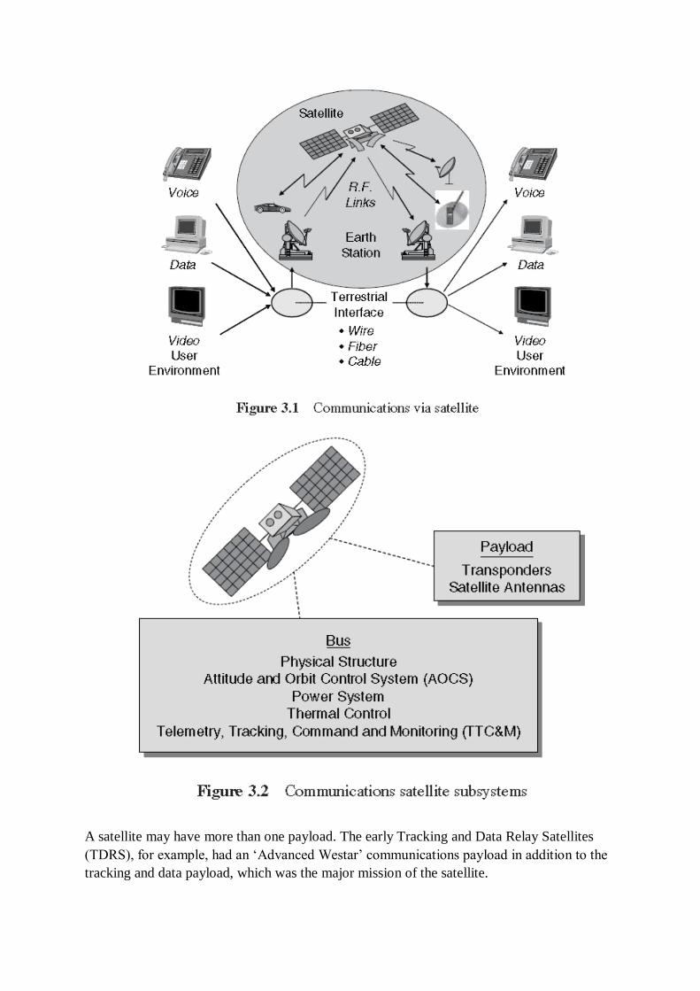
An operating communications satellite system consists of several elements or segments,
ranging from an orbital configuration of space components to ground based components and
network elements. The particular application of the satellite system, for example fixed
satellite service, mobile service, or broadcast service, will determine the specific elements of
the system. A generic satellite system, applicable to most satellite applications, can be
described by the elements shown in Figure 3.1.
The basic system consists of a satellite (or satellites) in space, relaying information between
two or more users through ground terminals and the satellite. The information relayed may be
voice, data, video, or a combination of the three. The user information may require
transmission via terrestrial means to connect with the ground terminal. The satellite is
controlled from the ground through a satellite control facility, often called the master control
center (MCC), which provides tracking, telemetry, command, and monitoring functions for
the system.
The space segment of the satellite system consists of the orbiting satellite (or satellites) and
the ground satellite control facilities necessary to keep the satellites operational. The
ground segment, or earth segment, of the satellite system consists of the transmit and
receive earth stations and the associated equipment to interface with the user network.
Ground segment elements are unique to the type of communications satellite application,
such as fixed service, mobile service, broadcast service, or satellite broadband, and will be
covered in later chapters where the specific applications are discussed. The space segment
equipment carried aboard the satellite can be classified under two functional areas: the bus
and the payload, as shown in Figure 3.2.
• Bus The bus refers to the basic satellite structure itself and the subsystems that support the
satellite. The bus subsystems are: the physical structure, power subsystem, attitude and orbital
control subsystem, thermal control subsystem, and command and telemetry subsystem.
Payload The payload on a satellite is the equipment that provides the service or services
intended for the satellite. A communications satellite payload consists of the communications
equipment that provides the relay link between the up- and downlinks from the ground. The
communications payload can be further divided into the transponder and the antenna
subsystems.
A satellite may have more than one payload. The early Tracking and Data Relay Satellites
(TDRS), for example, had an ‗Advanced Westar‘ communications payload in addition to the
tracking and data payload, which was the major mission of the satellite.
4.1 ATTITUDE AND ORBIT CONTROL SYSTEM
Satellite Bus
The basic characteristics of each of the bus subsystems are described in the
following subsections.
Physical Structure
The physical structure of the satellite provides a ‗home‘ for all the components of the
satellite.
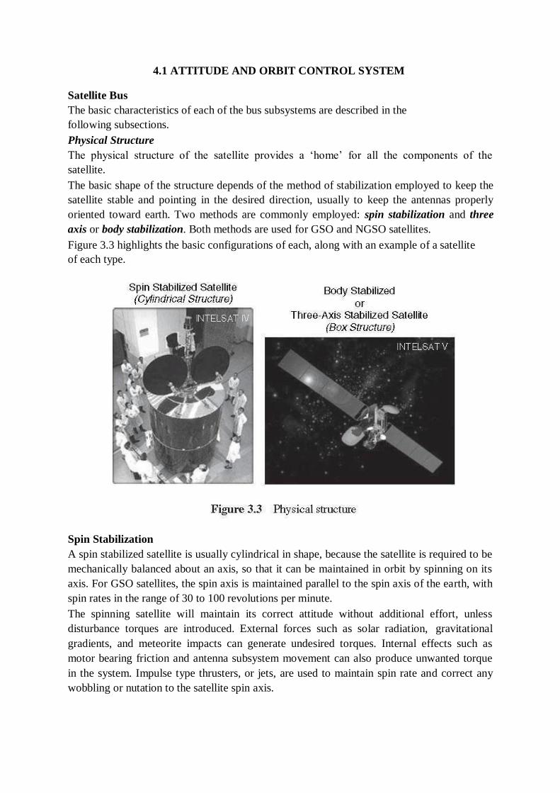
The basic shape of the structure depends of the method of stabilization employed to keep the
satellite stable and pointing in the desired direction, usually to keep the antennas properly
oriented toward earth. Two methods are commonly employed: spin stabilization and three
axis or body stabilization. Both methods are used for GSO and NGSO satellites.
Figure 3.3 highlights the basic configurations of each, along with an example of a satellite
of each type.
Spin Stabilization
A spin stabilized satellite is usually cylindrical in shape, because the satellite is required to be
mechanically balanced about an axis, so that it can be maintained in orbit by spinning on its
axis. For GSO satellites, the spin axis is maintained parallel to the spin axis of the earth, with
spin rates in the range of 30 to 100 revolutions per minute.
The spinning satellite will maintain its correct attitude without additional effort, unless
disturbance torques are introduced. External forces such as solar radiation, gravitational
gradients, and meteorite impacts can generate undesired torques. Internal effects such as
motor bearing friction and antenna subsystem movement can also produce unwanted torque
in the system. Impulse type thrusters, or jets, are used to maintain spin rate and correct any
wobbling or nutation to the satellite spin axis.
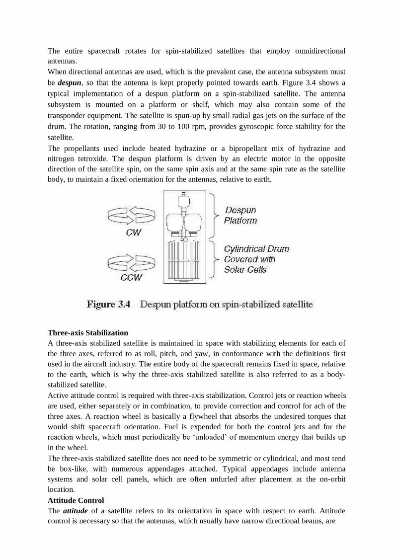
The entire spacecraft rotates for spin-stabilized satellites that employ omnidirectional
antennas.
When directional antennas are used, which is the prevalent case, the antenna subsystem must
be despun, so that the antenna is kept properly pointed towards earth. Figure 3.4 shows a
typical implementation of a despun platform on a spin-stabilized satellite. The antenna
subsystem is mounted on a platform or shelf, which may also contain some of the
transponder equipment. The satellite is spun-up by small radial gas jets on the surface of the
drum. The rotation, ranging from 30 to 100 rpm, provides gyroscopic force stability for the
satellite.
The propellants used include heated hydrazine or a bipropellant mix of hydrazine and
nitrogen tetroxide. The despun platform is driven by an electric motor in the opposite
direction of the satellite spin, on the same spin axis and at the same spin rate as the satellite
body, to maintain a fixed orientation for the antennas, relative to earth.
Three-axis Stabilization
A three-axis stabilized satellite is maintained in space with stabilizing elements for each of
the three axes, referred to as roll, pitch, and yaw, in conformance with the definitions first
used in the aircraft industry. The entire body of the spacecraft remains fixed in space, relative
to the earth, which is why the three-axis stabilized satellite is also referred to as a body-
stabilized satellite.
Active attitude control is required with three-axis stabilization. Control jets or reaction wheels
are used, either separately or in combination, to provide correction and control for ach of the
three axes. A reaction wheel is basically a flywheel that absorbs the undesired torques that
would shift spacecraft orientation. Fuel is expended for both the control jets and for the
reaction wheels, which must periodically be ‗unloaded‘ of momentum energy that builds up
in the wheel.
The three-axis stabilized satellite does not need to be symmetric or cylindrical, and most tend
be box-like, with numerous appendages attached. Typical appendages include antenna
systems and solar cell panels, which are often unfurled after placement at the on-orbit
location.
Attitude Control
The attitude of a satellite refers to its orientation in space with respect to earth. Attitude
control is necessary so that the antennas, which usually have narrow directional beams, are
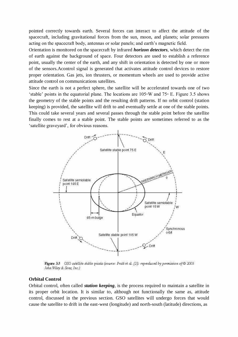
pointed correctly towards earth. Several forces can interact to affect the attitude of the
spacecraft, including gravitational forces from the sun, moon, and planets; solar pressures
acting on the spacecraft body, antennas or solar panels; and earth‘s magnetic field.
Orientation is monitored on the spacecraft by infrared horizon detectors, which detect the rim
of earth against the background of space. Four detectors are used to establish a reference
point, usually the center of the earth, and any shift in orientation is detected by one or more
of the sensors.Acontrol signal is generated that activates attitude control devices to restore
proper orientation. Gas jets, ion thrusters, or momentum wheels are used to provide active
attitude control on communications satellites.
Since the earth is not a perfect sphere, the satellite will be accelerated towards one of two
‗stable‘ points in the equatorial plane. The locations are 105◦W and 75◦ E. Figure 3.5 shows
the geometry of the stable points and the resulting drift patterns. If no orbit control (station
keeping) is provided, the satellite will drift to and eventually settle at one of the stable points.
This could take several years and several passes through the stable point before the satellite
finally comes to rest at a stable point. The stable points are sometimes referred to as the
‗satellite graveyard‘, for obvious reasons.
Orbital Control
Orbital control, often called station keeping, is the process required to maintain a satellite in
its proper orbit location. It is similar to, although not functionally the same as, attitude
control, discussed in the previous section. GSO satellites will undergo forces that would
cause the satellite to drift in the east-west (longitude) and north-south (latitude) directions, as
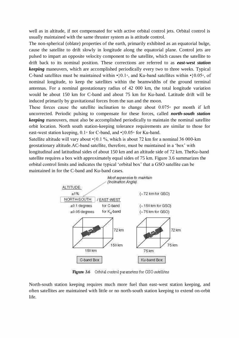
well as in altitude, if not compensated for with active orbital control jets. Orbital control is
usually maintained with the same thruster system as is attitude control.
The non-spherical (oblate) properties of the earth, primarily exhibited as an equatorial bulge,
cause the satellite to drift slowly in longitude along the equatorial plane. Control jets are
pulsed to impart an opposite velocity component to the satellite, which causes the satellite to
drift back to its nominal position. These corrections are referred to as east-west station
keeping maneuvers, which are accomplished periodically every two to three weeks. Typical
C-band satellites must be maintained within •}0.1◦, and Ku-band satellites within •}0.05◦, of
nominal longitude, to keep the satellites within the beamwidths of the ground terminal
antennas. For a nominal geostationary radius of 42 000 km, the total longitude variation
would be about 150 km for C-band and about 75 km for Ku-band. Latitude drift will be
induced primarily by gravitational forces from the sun and the moon.
These forces cause the satellite inclination to change about 0.075◦ per month if left
uncorrected. Periodic pulsing to compensate for these forces, called north-south station
keeping maneuvers, must also be accomplished periodically to maintain the nominal satellite
orbit location. North south station-keeping tolerance requirements are similar to those for
east-west station keeping, 0.1◦ for C-band, and •}0.05◦ for Ku-band.
Satellite altitude will vary about •}0.1 %, which is about 72 km for a nominal 36 000-km
geostationary altitude.AC-band satellite, therefore, must be maintained in a ‗box‘ with
longitudinal and latitudinal sides of about 150 km and an altitude side of 72 km. TheKu-band
satellite requires a box with approximately equal sides of 75 km. Figure 3.6 summarizes the
orbital control limits and indicates the typical ‗orbital box‘ that a GSO satellite can be
maintained in for the C-band and Ku-band cases.
North-south station keeping requires much more fuel than east-west station keeping, and
often satellites are maintained with little or no north-south station keeping to extend on-orbit
life.
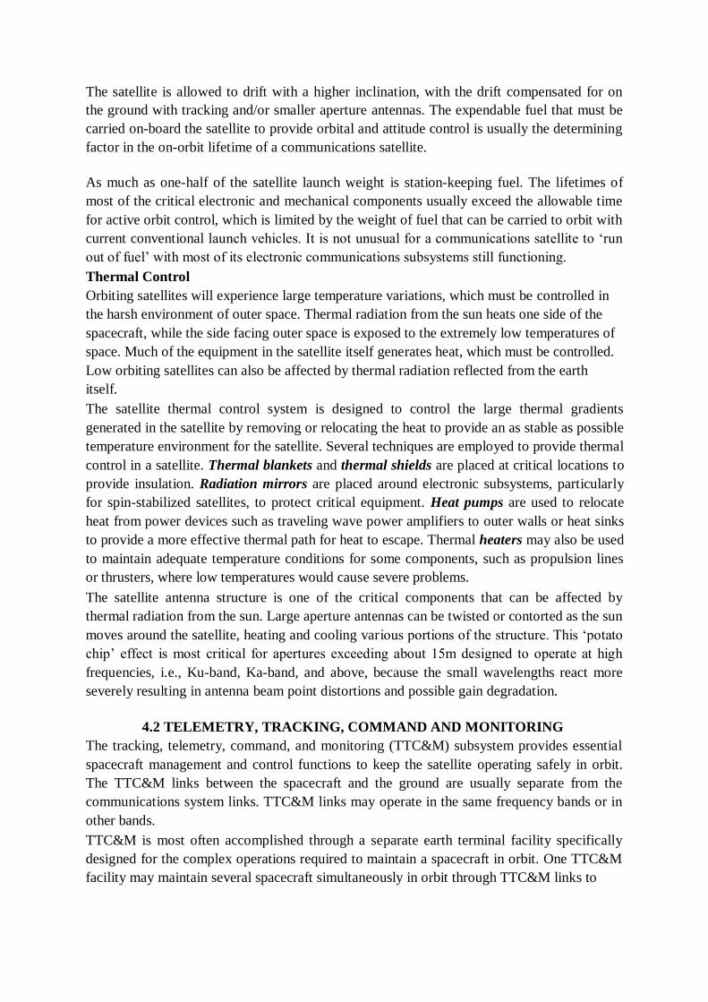
The satellite is allowed to drift with a higher inclination, with the drift compensated for on
the ground with tracking and/or smaller aperture antennas. The expendable fuel that must be
carried on-board the satellite to provide orbital and attitude control is usually the determining
factor in the on-orbit lifetime of a communications satellite.
As much as one-half of the satellite launch weight is station-keeping fuel. The lifetimes of
most of the critical electronic and mechanical components usually exceed the allowable time
for active orbit control, which is limited by the weight of fuel that can be carried to orbit with
current conventional launch vehicles. It is not unusual for a communications satellite to ‗run
out of fuel‘ with most of its electronic communications subsystems still functioning.
Thermal Control
Orbiting satellites will experience large temperature variations, which must be controlled in
the harsh environment of outer space. Thermal radiation from the sun heats one side of the
spacecraft, while the side facing outer space is exposed to the extremely low temperatures of
space. Much of the equipment in the satellite itself generates heat, which must be controlled.
Low orbiting satellites can also be affected by thermal radiation reflected from the earth
itself.
The satellite thermal control system is designed to control the large thermal gradients
generated in the satellite by removing or relocating the heat to provide an as stable as possible
temperature environment for the satellite. Several techniques are employed to provide thermal
control in a satellite. Thermal blankets and thermal shields are placed at critical locations to
provide insulation. Radiation mirrors are placed around electronic subsystems, particularly
for spin-stabilized satellites, to protect critical equipment. Heat pumps are used to relocate
heat from power devices such as traveling wave power amplifiers to outer walls or heat sinks
to provide a more effective thermal path for heat to escape. Thermal heaters may also be used
to maintain adequate temperature conditions for some components, such as propulsion lines
or thrusters, where low temperatures would cause severe problems.
The satellite antenna structure is one of the critical components that can be affected by
thermal radiation from the sun. Large aperture antennas can be twisted or contorted as the sun
moves around the satellite, heating and cooling various portions of the structure. This ‗potato
chip‘ effect is most critical for apertures exceeding about 15m designed to operate at high
frequencies, i.e., Ku-band, Ka-band, and above, because the small wavelengths react more
severely resulting in antenna beam point distortions and possible gain degradation.
4.2 TELEMETRY, TRACKING, COMMAND AND MONITORING
The tracking, telemetry, command, and monitoring (TTC&M) subsystem provides essential
spacecraft management and control functions to keep the satellite operating safely in orbit.
The TTC&M links between the spacecraft and the ground are usually separate from the
communications system links. TTC&M links may operate in the same frequency bands or in
other bands.
TTC&M is most often accomplished through a separate earth terminal facility specifically
designed for the complex operations required to maintain a spacecraft in orbit. One TTC&M
facility may maintain several spacecraft simultaneously in orbit through TTC&M links to
each vehicle. Figure 3.7 shows the typical TTC&M functional elements for the satellite and
ground facility for a communications satellite application.
The satellite TTC&M subsystems comprise the antenna, command receiver, tracking and
telemetry transmitter, and possibly tracking sensors. Telemetry data are received from the
other subsystems of the spacecraft, such as the payload, power, attitude control, and thermal
control. Command data are relayed from the command receiver to other subsystems to
control such parameters as antenna pointing, transponder modes of operation, battery and
solar cell changes, etc.
The elements on the ground include the TTC&M antenna, telemetry receiver, command
transmitter, tracking subsystem, and associated processing and analysis functions. Satellite
control and monitoring is accomplished through monitors and keyboard interface. Major
operations of TTC&M may be automated, with minimal human interface required.
Tracking refers to the determination of the current orbit, position, and movement of the
spacecraft. The tracking function is accomplished by a number of techniques, usually
involving satellite beacon signals, which are received at the satellite TTC&M earth station.
The Doppler shift of the beacon (or the telemetry carrier) is monitored to determine the rate
at which the range is changing (the range rate). Angular measurements from one or more
earth terminals can be used to determine spacecraft location. The range can be determined by
observing the time delay of a pulse or sequence of pulses transmitted from the satellite.
Acceleration and velocity sensors on the satellite can be used to monitor orbital location and
changes in orbital location.
The telemetry function involves the collection of data from sensors on-board the spacecraft
and the relay of this information to the ground. The telemetered data include such parameters
as voltage and current conditions in the power subsystem, temperature of critical subsystems,
status of switches and relays in the communications and antenna subsystems, fuel tank
pressures, and attitude control sensor status. A typical communications satellite telemetry link
could involve over 100 channels of sensor information, usually in digital form, but
occasionally in analog form for diagnostic evaluations. The telemetry carrier modulation is
typically frequency or phase shift keying (FSK or PSK), with the telemetry channels
transmitted in a time division multiplex (TDM) format. Telemetry channel data rates are low,
usually only a few kbps.
Command is the complementary function to telemetry. The command system relays specific
control and operations information from the ground to the spacecraft, often in response to
telemetry information received from the spacecraft. Parameters involved in typical command
links include changes and corrections in attitude control and orbital control;
• antenna pointing and control;
• transponder mode of operation;
• battery voltage control.
The command system is used during launch to control the firing of the boost motor, deploy
appendages such as solar panels and antenna reflectors, and ‗spin-up‘ a spin-stabilized
spacecraft body. Security is an important factor in the command system for a communications
satellite. The structure of the command system must contain safeguards against intentional or
unintentional signals corrupting the command link, or unauthorized commands from being
transmitted and accepted by the spacecraft. Command links are nearly always encrypted with
a secure code format to maintain the health and safety of the satellite. The command
procedure also involves multiple transmissions to the spacecraft, to assure the validity and
correct reception of the command, before the execute instruction is transmitted. Telemetry
and command during the launch and transfer orbit phases usually requires a backup TTC&M
system, since the main TTC&M system may be inoperable because the antenna is not
deployed, or the spacecraft attitude is not proper for transmission to earth. The backup system
usually operates with an omnidirectional antenna, at UHF or S-band, with sufficient margin
to allow operation in the most adverse conditions. The backup system could also be used if
the main TTC&M system fails on orbit.
4.3 POWER SYSTEMS
The electrical power for operating equipment on a communications satellite is obtained
primarily from solar cells, which convert incident sunlight into electrical energy. The
radiation on a satellite from the sun has an intensity averaging about 1.4 kW/m2. Solar cells
operate at an efficiency of 20–25% at beginning of life (BOL), and can degrade to 5–10% at
end of life (EOL), usually considered to be 15 years. Because of this, large numbers of cells,
connected in serial-parallel arrays, are required to support the communications satellite
electronic systems, which often require more than one to two kilowatts of prime power to
function. The spin-stabilized satellite usually has cylindrical panels, which may be extended
after deployment to provide additional exposure area. A cylindrical spin-stabilized satellite
must carry a larger number of solar cells than an equivalent three-axis stabilized satellite,
because only about one-third of the cells are exposed to the sun at any one time.
The three-axis stabilized satellite configuration allows for better utilization of solar cell area,
because the cells can be arranged in flat panels, or sails, which can be rotated to maintain
normal exposure to the sun – levels up to 10kW are attainable with rotating panels. All
spacecraft must also carry storage batteries to provide power during launch and during eclipse
periods when sun blockage occurs. Eclipses occur for a GSO satellite twice a year, around the
spring and fall equinoxes, when earth‘s shadow passes across the spacecraft. Daily eclipses
start about 23 days before the equinox, and end the same number of days after. The daily
eclipse duration increases a few minutes each day to about a 70-minute peak on equinox day,
then decreases a similar amount each day following the peak. Sealed nickel cadmium (Ni-Cd)
batteries are most often used for satellite battery systems. They have good reliability and long
life, and do not outgas when in a charging cycle. Nickel-hydrogen (NiH2) batteries, which
provide a significant improvement in power-to-weight ratio, are also used. A power
conditioning unit is also included in the power subsystem, for the control of battery charging
and for power regulation and monitoring.
The power generating and control systems on a communications satellite account for a large
part of its weight, often 10 to 20% of total dry weight.
4.4 COMMUNICATION SUBSYSTEM
Satellite Payload
The next two sections discuss the key elements of the payload portion of the space segment,
specifically for communications satellite systems: the transponder and antenna subsystems.
Transponder
The transponder in a communications satellite is the series of components that provides the
communications channel, or link, between the uplink signal received at the uplink antenna,
and the downlink signal transmitted by the downlink antenna. A typical communications
satellite will contain several transponders, and some of the equipment may be common to
more than one transponder.
Each transponder generally operates in a different frequency band, with the allocated
frequency spectrum band divided into slots, with a specified center frequency and operating
bandwidth. The C-band FSS service allocation, for example, is 500MHz wide. A typical
design would accommodate 12 transponders, each with a bandwidth of 36 MHz, with guard
bands of 4MHz between each.Atypical commercial communications satellite today can have
24 to 48 transponders, operating in the C-band, Ku-band, or Ka-bands. The number of
transponders can be doubled by the use of polarization frequency reuse, where two carriers
at the same frequency, but with orthogonal polarization, are used. Both linear polarization
(horizontal and vertical sense) and circular polarization (right-hand and left-hand sense) have
been used. Additional frequency reuse may be achieved through spatial separation of the
signals, in the form of narrow spot beams, which allow the reuse of the same frequency
carrier for physically separate locations on the earth. Polarization reuse and spot beams can
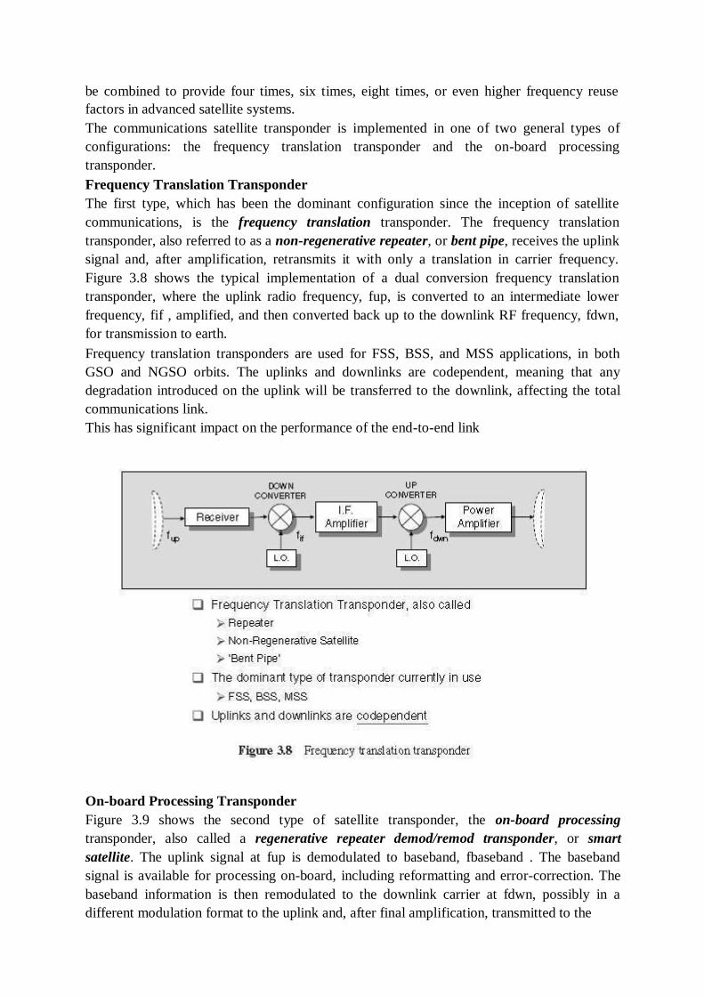
be combined to provide four times, six times, eight times, or even higher frequency reuse
factors in advanced satellite systems.
The communications satellite transponder is implemented in one of two general types of
configurations: the frequency translation transponder and the on-board processing
transponder.
Frequency Translation Transponder
The first type, which has been the dominant configuration since the inception of satellite
communications, is the frequency translation transponder. The frequency translation
transponder, also referred to as a non-regenerative repeater, or bent pipe, receives the uplink
signal and, after amplification, retransmits it with only a translation in carrier frequency.
Figure 3.8 shows the typical implementation of a dual conversion frequency translation
transponder, where the uplink radio frequency, fup, is converted to an intermediate lower
frequency, fif , amplified, and then converted back up to the downlink RF frequency, fdwn,
for transmission to earth.
Frequency translation transponders are used for FSS, BSS, and MSS applications, in both
GSO and NGSO orbits. The uplinks and downlinks are codependent, meaning that any
degradation introduced on the uplink will be transferred to the downlink, affecting the total
communications link.
This has significant impact on the performance of the end-to-end link
On-board Processing Transponder
Figure 3.9 shows the second type of satellite transponder, the on-board processing
transponder, also called a regenerative repeater demod/remod transponder, or smart
satellite. The uplink signal at fup is demodulated to baseband, fbaseband . The baseband
signal is available for processing on-board, including reformatting and error-correction. The
baseband information is then remodulated to the downlink carrier at fdwn, possibly in a
different modulation format to the uplink and, after final amplification, transmitted to the
ground. The demodulation/remodulation process removes uplink noise and interference from
the downlink, while allowing additional on-board processing to be accomplished. Thus the
uplinks and downlinks are independent with respect to evaluation of overall link
performance, unlike the frequency translation transponder where uplink degradations are
codependent, as discussed earlier.
On-board processing satellites tend to be more complex and expensive than frequency
translation satellites; however, they offer significant performance advantages, particularly for
small terminal users or for large diverse networks. The performance of the on-board
processing satellite‘s composite link is discussed further in Chapter 9.
Traveling wave tube amplifiers (TWTAs) or solid state amplifiers (SSPAs) are used to
provide the final output power required for each transponder channel. The TWTA is a slow
wave structure device, which operates in a vacuum envelope, and requires permanent magnet
focusing and high voltage DC power supply support systems. The major advantage of the
TWTA is its wide bandwidth capability at microwave frequencies. TWTAs for space
applications can operate to well above 30 GHz, with output powers of 150 watts or more, and
RF bandwidths exceeding 1 GHz. SSPAs are used when power requirements in the 2–20 watt
region are required. SSPAs operate with slightly better power efficiency than the TWTA,
however both are nonlinear devices, which directly impacts system performance, as we shall
see when RF link performance is discussed in later chapters.
Other devices may be included in the basic transponder configurations of Figures 3.8 and 3.9,
including band pass filters, switches, input multiplexers, switch matrices, and output
multiplexers. Each device must be considered when evaluating the signal losses and system
performance of the space segment of the satellite network.
4.5 SATELLITE ANTENNA
Antennas
The antenna systems on the spacecraft are used for transmitting and receiving the RF signals
that comprise the space links of the communications channels. The antenna system is a
critical part of the satellite communications system, because it is the essential element in
increasing the strength of the transmitted or received signal to allow amplification,
processing, and eventual retransmission.
The most important parameters that define the performance of an antenna are antenna gain,
antenna beamwidth, and antenna sidelobes. The gain defines the increase in strength achieved
in concentrating the radio wave energy, either in transmission or reception, by the antenna
system.
The antenna gain is usually expressed in dBi, decibels above an isotropic antenna, which is
an antenna that radiates uniformly in all directions. The beamwidth is usually expressed as
the half-power beamwidth or the 3-dB beamwidth, which is a measure of the angle over
which maximum gain occurs. The sidelobes define the amount of gain in the off-axis
directions.
Most satellite communications applications require an antenna to be highly directional (high
gain, narrow beamwidth) with negligibly small sidelobes.
The common types of antennas used in satellite systems are the linear dipole, the horn
antenna, the parabolic reflector, and the array antenna. The linear dipole antenna is an
isotropic radiator that radiates uniformly in all directions. Four or more dipole antennas are
placed on the spacecraft to obtain a nearly omni-directional pattern. Dipole antennas are used
primarily at VHF and UHF for tracking, telemetry, and command links. Dipole antennas are
also important during launch operations, where the spacecraft attitude has not yet been
established, and for satellites that operate without attitude control or body stabilization
(particularly for LEO systems).
Horn antennas are used at frequencies from about 4 GHz and up, when relatively wide
beams are required, such as global coverage from a GSO satellite. A horn is a flared section
of waveguide that provides gains of up to about 20 dBi, with beamwidths of 10◦ or higher. If
higher gains or narrower bandwidths are required, a reflector or array antenna must be used.
The most often used antenna for satellite systems, particularly for those operating above
10 GHz, is the parabolic reflector antenna. Parabolic reflector antennas are usually
illuminated by one or more horn antenna feeds at the focus of the paroboloid. Parabolic
reflectors offer a much higher gain than that achievable by the horn antenna alone. Gains of
25 dB and higher, with beamwidths of 1◦ or less, are achievable with parabolic reflector
antennas operating in the C, Ku, or Ka bands. Narrow beam antennas usually require physical
pointing mechanisms (gimbals) on the spacecraft to point the beam in the desired direction.
There is increasing interest in the use of array antennas for satellite communications
applications.
A steerable, focused beam can be formed by combining the radiation from several small
elements made up of dipoles, helices, or horns. Beam forming can be achieved by
electronically phase shifting the signal at each element. Proper selection of the phase
characteristics between the elements allows the direction and beamwidth to be controlled,
without physical movement of the antenna system. The array antenna gain increases with the
square of the number of elements. Gains and beamwidths comparable to those available from
parabolic reflector antennas can be achieved with array antennas.
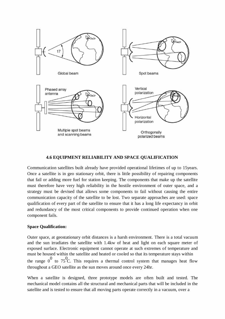
C
4.6 EQUIPMENT RELIABILITY AND SPACE QUALIFICATION
Communication satellites built already have provided operational lifetimes of up to 15years.
Once a satellite is in geo stationary orbit, there is little possibility of repairing components
that fail or adding more fuel for station keeping. The components that make up the satellite
must therefore have very high reliability in the hostile environment of outer space, and a
strategy must be devised that allows some components to fail without causing the entire
communication capacity of the satellite to be lost. Two separate approaches are used: space
qualification of every part of the satellite to ensure that it has a long life expectancy in orbit
and redundancy of the most critical components to provide continued operation when one
component fails.
Space Qualification:
Outer space, at geostationary orbit distances is a harsh environment. There is a total vacuum
and the sun irradiates the satellite with 1.4kw of heat and light on each square meter of
exposed surface. Electronic equipment cannot operate at such extremes of temperature and
must be housed within the satellite and heated or cooled so that its temperature stays within
the range 00
to 750
. This requires a thermal control system that manages heat flow
throughout a GEO satellite as the sun moves around once every 24hr.
When a satellite is designed, three prototype models are often built and tested. The
mechanical model contains all the structural and mechanical parts that will be included in the
satellite and is tested to ensure that all moving parts operate correctly in a vacuum, over a

wide temperature range. The thermal model contains all the electronics packages and other
components that must be maintained at correct temperature. The electrical model contains all
electronic parts of the satellite and is tested for correct electrical performance under total
vacuum and a wide range of temperatures.
Many of the electronic and mechanical components that are used in satellite are known to
have limited life times, or a finite probability of failure. If failure of one of these components
will jeopardize the mission or reduce the communication capacity of the satellite, a backup,
or redundant, unit will provided. The design of the system must be such that when one unit
fails, the backup can automatically take over or be switched into operation by a command
from the ground.
Reliability
Reliability is counted by considering the proper working of satellites critical components.
Reliability could be improved by making the critical components redundant. Components
with a limited lifetime such as travelling wave tube amplifier etc should be made redundant.
Travelling Wave Tube Amplifier (TWTA): travelling wave tube amplifiers have applications
in both receiver and transmitter systems, and come in all shapes and sizes, but they all consist
of three basic parts-the tube, the tube mount (which includes the beam focussing magnets)
and the power supply.
The main attraction of these devices is their very high gain (30-60 dB), linear characteristics
and 1-2 octave bandwidth. They are quite widely used professionally, but are still rather
scarce in amateur circles. This article describes a little of the theory of twts, and explains how
to use them, in the hope that more amateurs may be able to acquire and use these fascinating
components.
When used as receiver RF amplifiers they are characterized by high gain, low noise figure
and wide bandwidth, and are known as low noise amplifiers (LNAS). These usually come
with tube, mount and power supply in one integral unit, with no external adjustments to
make-just input socket, output socket and mains supply connections. A typical LNA has an
octave bandwidth (eg 2-4 GHz), 30 dB gain, 8 dB noise figure, and a saturated power output
of 10 mW, within a volume of 2 in by 2 in by 10 in.
Transmitter TWTAs are naturally somewhat bulkier, and often have the poweror supplies as
a separate unit. Medium-power tubes have outputs of up to about 10 W, while high-power
tubes deliver several hundred watts. Such tubes have gains of the order of 30 or 40 dB, and
bandwidths of up to an octave.
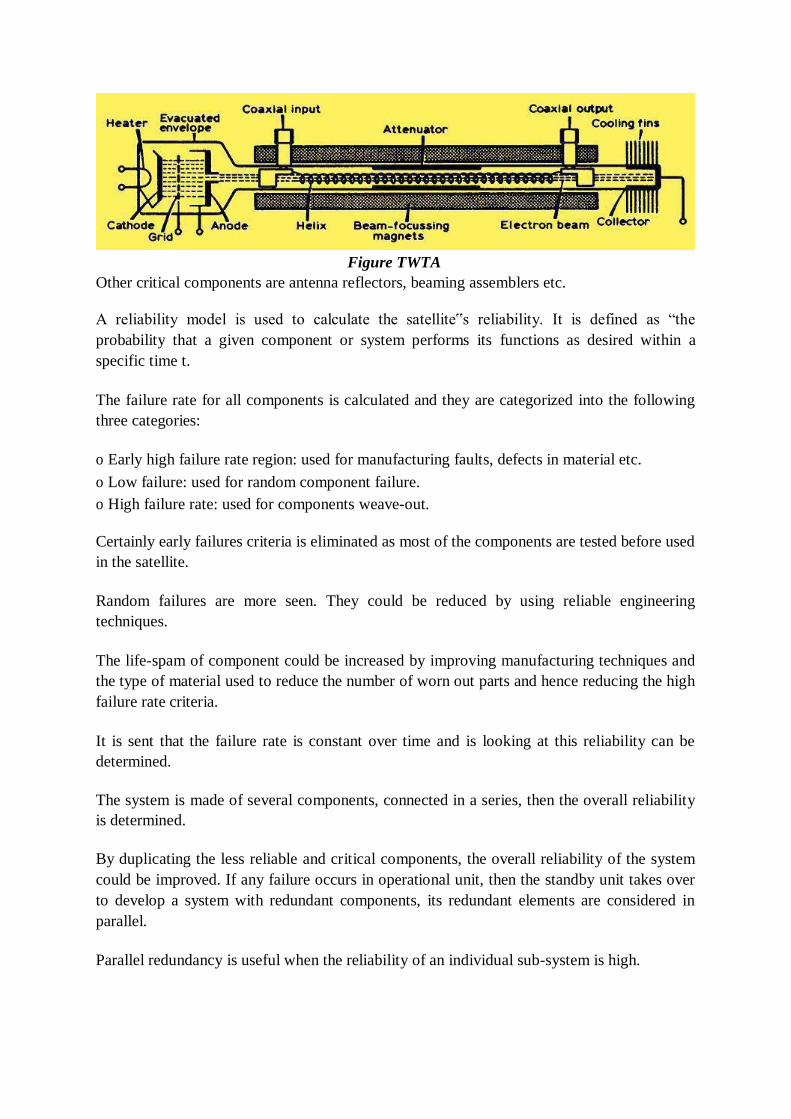
Figure TWTA
Other critical components are antenna reflectors, beaming assemblers etc.
A reliability model is used to calculate the satellite‟s reliability. It is defined as ―the
probability that a given component or system performs its functions as desired within a
specific time t.
The failure rate for all components is calculated and they are categorized into the following
three categories:
o Early high failure rate region: used for manufacturing faults, defects in material etc.
o Low failure: used for random component failure.
o High failure rate: used for components weave-out.
Certainly early failures criteria is eliminated as most of the components are tested before used
in the satellite.
Random failures are more seen. They could be reduced by using reliable engineering
techniques.
The life-spam of component could be increased by improving manufacturing techniques and
the type of material used to reduce the number of worn out parts and hence reducing the high
failure rate criteria.
It is sent that the failure rate is constant over time and is looking at this reliability can be
determined.
The system is made of several components, connected in a series, then the overall reliability
is determined.
By duplicating the less reliable and critical components, the overall reliability of the system
could be improved. If any failure occurs in operational unit, then the standby unit takes over
to develop a system with redundant components, its redundant elements are considered in
parallel.
Parallel redundancy is useful when the reliability of an individual sub-system is high.
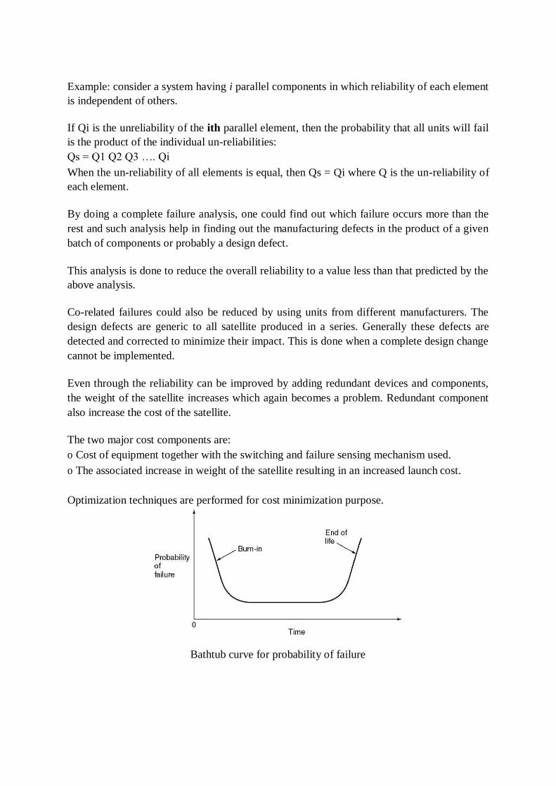
Example: consider a system having i parallel components in which reliability of each element
is independent of others.
If Qi is the unreliability of the ith parallel element, then the probability that all units will fail
is the product of the individual un-reliabilities:
Qs = Q1 Q2 Q3 …. Qi
When the un-reliability of all elements is equal, then Qs = Qi where Q is the un-reliability of
each element.
By doing a complete failure analysis, one could find out which failure occurs more than the
rest and such analysis help in finding out the manufacturing defects in the product of a given
batch of components or probably a design defect.
This analysis is done to reduce the overall reliability to a value less than that predicted by the
above analysis.
Co-related failures could also be reduced by using units from different manufacturers. The
design defects are generic to all satellite produced in a series. Generally these defects are
detected and corrected to minimize their impact. This is done when a complete design change
cannot be implemented.
Even through the reliability can be improved by adding redundant devices and components,
the weight of the satellite increases which again becomes a problem. Redundant component
also increase the cost of the satellite.
The two major cost components are:
o Cost of equipment together with the switching and failure sensing mechanism used.
o The associated increase in weight of the satellite resulting in an increased launch cost.
Optimization techniques are performed for cost minimization purpose.
Bathtub curve for probability of failure
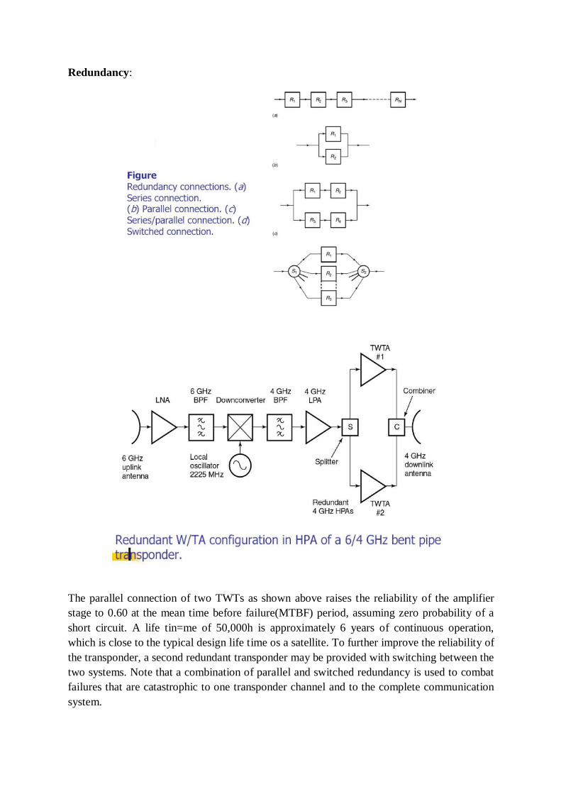
Redundancy:
The parallel connection of two TWTs as shown above raises the reliability of the amplifier
stage to 0.60 at the mean time before failure(MTBF) period, assuming zero probability of a
short circuit. A life tin=me of 50,000h is approximately 6 years of continuous operation,
which is close to the typical design life time os a satellite. To further improve the reliability of
the transponder, a second redundant transponder may be provided with switching between the
two systems. Note that a combination of parallel and switched redundancy is used to combat
failures that are catastrophic to one transponder channel and to the complete communication
system.

References
1. www.wikipedia.com
2. http://www.tech-faq.com/vsat.html
3. M. Richharia, Mobile Satellite Communication: Principles and Trends, Pearson Education
4. Rappaort, Wireless Communications Principals and Practices
5. YI Bing Lin , Wireless and Mobile Network Architectures, John Wiley
6. P. Nicopolitidis ,Wireless Networks, John Wiley
7. Satellite Communications Dennis Roddy 3rd edition, Mc-Graw Hill publication
8. Satellite communications-Timothy Pratt, Charles Bostian and Jeremy Allnutt, WSE, Wiley Publications, 2nd Edition,2003.
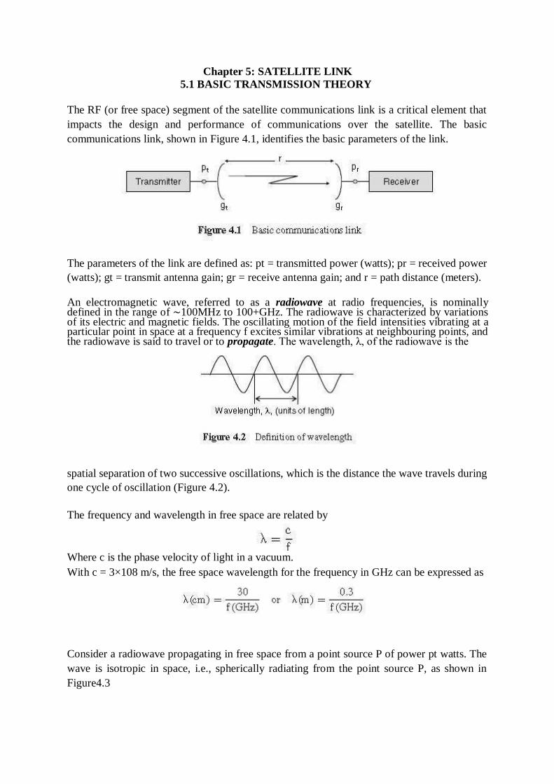
Chapter 5: SATELLITE LINK
5.1 BASIC TRANSMISSION THEORY
The RF (or free space) segment of the satellite communications link is a critical element that
impacts the design and performance of communications over the satellite. The basic
communications link, shown in Figure 4.1, identifies the basic parameters of the link.
The parameters of the link are defined as: pt = transmitted power (watts); pr = received power
(watts); gt = transmit antenna gain; gr = receive antenna gain; and r = path distance (meters).
An electromagnetic wave, referred to as a radiowave at radio frequencies, is nominally defined in the range of ∼100MHz to 100+GHz. The radiowave is characterized by variations of its electric and magnetic fields. The oscillating motion of the field intensities vibrating at a particular point in space at a frequency f excites similar vibrations at neighbouring points, and the radiowave is said to travel or to propagate. The wavelength, λ, of the radiowave is the
spatial separation of two successive oscillations, which is the distance the wave travels during
one cycle of oscillation (Figure 4.2).
The frequency and wavelength in free space are related by
Where c is the phase velocity of light in a vacuum.
With c = 3×10⁸ m/s, the free space wavelength for the frequency in GHz can be expressed as
Consider a radiowave propagating in free space from a point source P of power pt watts. The
wave is isotropic in space, i.e., spherically radiating from the point source P, as shown in
Figure4.3
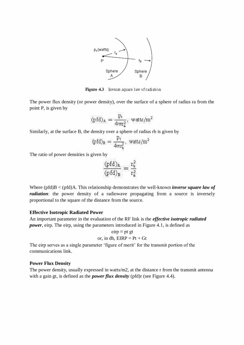
The power flux density (or power density), over the surface of a sphere of radius ra from the
point P, is given by
Similarly, at the surface B, the density over a sphere of radius rb is given by
The ratio of power densities is given by
Where (pfd)B < (pfd)A. This relationship demonstrates the well-known inverse square law of
radiation: the power density of a radiowave propagating from a source is inversely
proportional to the square of the distance from the source.
Effective Isotropic Radiated Power
An important parameter in the evaluation of the RF link is the effective isotropic radiated
power, eirp. The eirp, using the parameters introduced in Figure 4.1, is defined as
eirp ≡ pt gt
or, in db, EIRP = Pt + Gt
The eirp serves as a single parameter ‗figure of merit‘ for the transmit portion of the
communications link.
Power Flux Density
The power density, usually expressed in watts/m2, at the distance r from the transmit antenna
with a gain gt, is defined as the power flux density (pfd)r (see Figure 4.4).
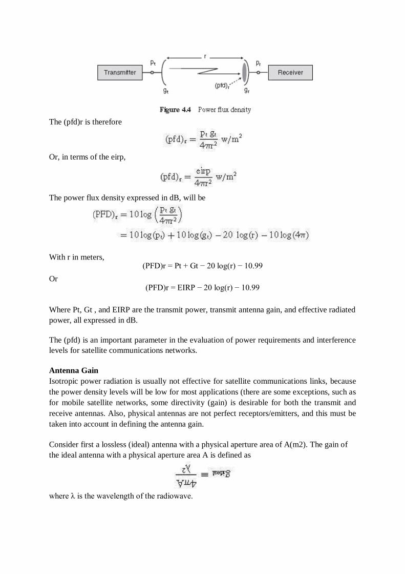
The (pfd)r is therefore
Or, in terms of the eirp,
The power flux density expressed in dB, will be
With r in meters,
Or
(PFD)r = Pt + Gt − 20 log(r) − 10.99
(PFD)r = EIRP − 20 log(r) − 10.99
Where Pt, Gt , and EIRP are the transmit power, transmit antenna gain, and effective radiated
power, all expressed in dB.
The (pfd) is an important parameter in the evaluation of power requirements and interference
levels for satellite communications networks.
Antenna Gain
Isotropic power radiation is usually not effective for satellite communications links, because
the power density levels will be low for most applications (there are some exceptions, such as
for mobile satellite networks, some directivity (gain) is desirable for both the transmit and
receive antennas. Also, physical antennas are not perfect receptors/emitters, and this must be
taken into account in defining the antenna gain.
Consider first a lossless (ideal) antenna with a physical aperture area of A(m2). The gain of
the ideal antenna with a physical aperture area A is defined as
where λ is the wavelength of the radiowave.
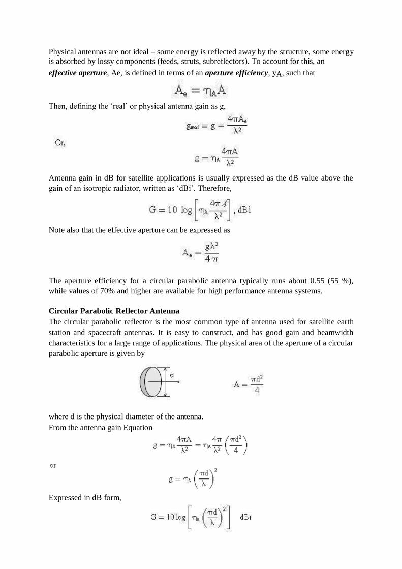
Physical antennas are not ideal – some energy is reflected away by the structure, some energy
is absorbed by lossy components (feeds, struts, subreflectors). To account for this, an
effective aperture, Ae, is defined in terms of an aperture efficiency, yA, such that
Then, defining the ‗real‘ or physical antenna gain as g,
Antenna gain in dB for satellite applications is usually expressed as the dB value above the
gain of an isotropic radiator, written as ‗dBi‘. Therefore,
Note also that the effective aperture can be expressed as
The aperture efficiency for a circular parabolic antenna typically runs about 0.55 (55 %),
while values of 70% and higher are available for high performance antenna systems.
Circular Parabolic Reflector Antenna
The circular parabolic reflector is the most common type of antenna used for satellite earth
station and spacecraft antennas. It is easy to construct, and has good gain and beamwidth
characteristics for a large range of applications. The physical area of the aperture of a circular
parabolic aperture is given by
where d is the physical diameter of the antenna.
From the antenna gain Equation
Expressed in dB form,
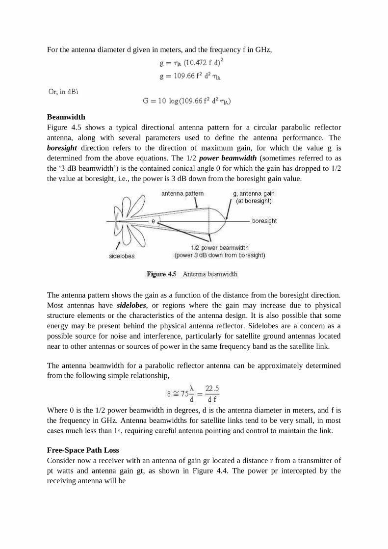
For the antenna diameter d given in meters, and the frequency f in GHz,
Beamwidth
Figure 4.5 shows a typical directional antenna pattern for a circular parabolic reflector
antenna, along with several parameters used to define the antenna performance. The
boresight direction refers to the direction of maximum gain, for which the value g is
determined from the above equations. The 1/2 power beamwidth (sometimes referred to as
the ‗3 dB beamwidth‘) is the contained conical angle 0 for which the gain has dropped to 1/2
the value at boresight, i.e., the power is 3 dB down from the boresight gain value.
The antenna pattern shows the gain as a function of the distance from the boresight direction.
Most antennas have sidelobes, or regions where the gain may increase due to physical
structure elements or the characteristics of the antenna design. It is also possible that some
energy may be present behind the physical antenna reflector. Sidelobes are a concern as a
possible source for noise and interference, particularly for satellite ground antennas located
near to other antennas or sources of power in the same frequency band as the satellite link.
The antenna beamwidth for a parabolic reflector antenna can be approximately determined
from the following simple relationship,
Where 0 is the 1/2 power beamwidth in degrees, d is the antenna diameter in meters, and f is
the frequency in GHz. Antenna beamwidths for satellite links tend to be very small, in most
cases much less than 1◦, requiring careful antenna pointing and control to maintain the link.
Free-Space Path Loss
Consider now a receiver with an antenna of gain gr located a distance r from a transmitter of
pt watts and antenna gain gt, as shown in Figure 4.4. The power pr intercepted by the
receiving antenna will be
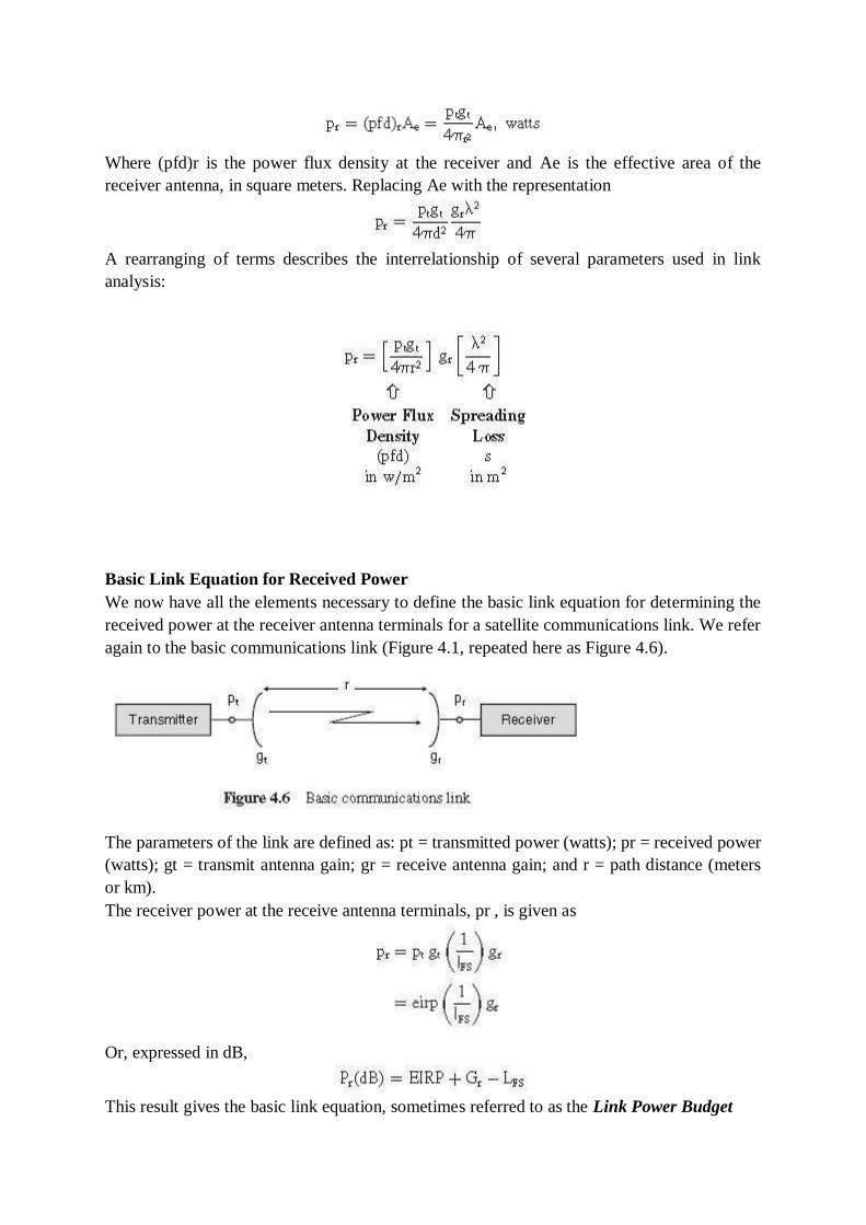
Where (pfd)r is the power flux density at the receiver and Ae is the effective area of the
receiver antenna, in square meters. Replacing Ae with the representation
A rearranging of terms describes the interrelationship of several parameters used in link
analysis:
Basic Link Equation for Received Power
We now have all the elements necessary to define the basic link equation for determining the
received power at the receiver antenna terminals for a satellite communications link. We refer
again to the basic communications link (Figure 4.1, repeated here as Figure 4.6).
The parameters of the link are defined as: pt = transmitted power (watts); pr = received power
(watts); gt = transmit antenna gain; gr = receive antenna gain; and r = path distance (meters
or km).
The receiver power at the receive antenna terminals, pr , is given as
Or, expressed in dB,
This result gives the basic link equation, sometimes referred to as the Link Power Budget
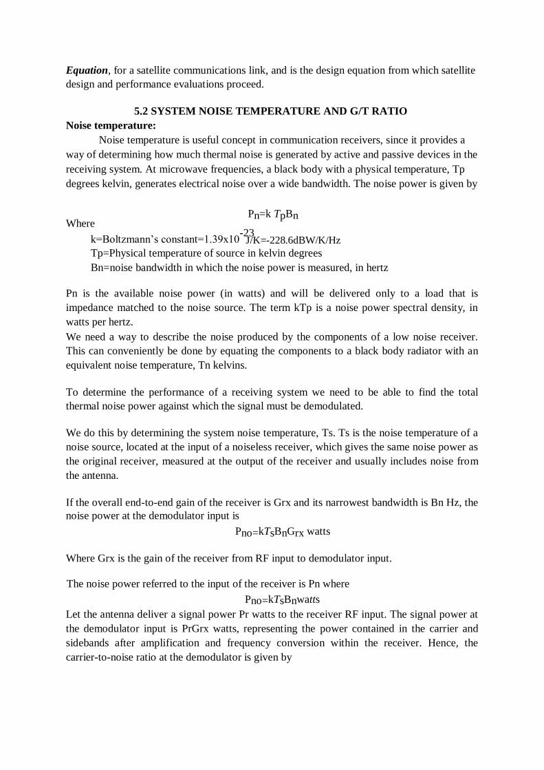
Equation, for a satellite communications link, and is the design equation from which satellite
design and performance evaluations proceed.
5.2 SYSTEM NOISE TEMPERATURE AND G/T RATIO
Noise temperature:
Noise temperature is useful concept in communication receivers, since it provides a
way of determining how much thermal noise is generated by active and passive devices in the
receiving system. At microwave frequencies, a black body with a physical temperature, Tp
degrees kelvin, generates electrical noise over a wide bandwidth. The noise power is given by
Where Pn=k TpBn
k=Boltzmann‘s constant=1.39x10⁻²³
Tp=Physical temperature of source in kelvin degrees
Bn=noise bandwidth in which the noise power is measured, in hertz
Pn is the available noise power (in watts) and will be delivered only to a load that is
impedance matched to the noise source. The term kTp is a noise power spectral density, in
watts per hertz.
We need a way to describe the noise produced by the components of a low noise receiver.
This can conveniently be done by equating the components to a black body radiator with an
equivalent noise temperature, Tn kelvins.
To determine the performance of a receiving system we need to be able to find the total
thermal noise power against which the signal must be demodulated.
We do this by determining the system noise temperature, Ts. Ts is the noise temperature of a
noise source, located at the input of a noiseless receiver, which gives the same noise power as
the original receiver, measured at the output of the receiver and usually includes noise from
the antenna.
If the overall end-to-end gain of the receiver is Grx and its narrowest bandwidth is Bn Hz, the
noise power at the demodulator input is
Pno=kTsBnGrx watts
Where Grx is the gain of the receiver from RF input to demodulator input.
The noise power referred to the input of the receiver is Pn where
Pno=kTsBnwatts
Let the antenna deliver a signal power Pr watts to the receiver RF input. The signal power at
the demodulator input is PrGrx watts, representing the power contained in the carrier and
sidebands after amplification and frequency conversion within the receiver. Hence, the
carrier-to-noise ratio at the demodulator is given by
J/K=-228.6dBW/K/Hz
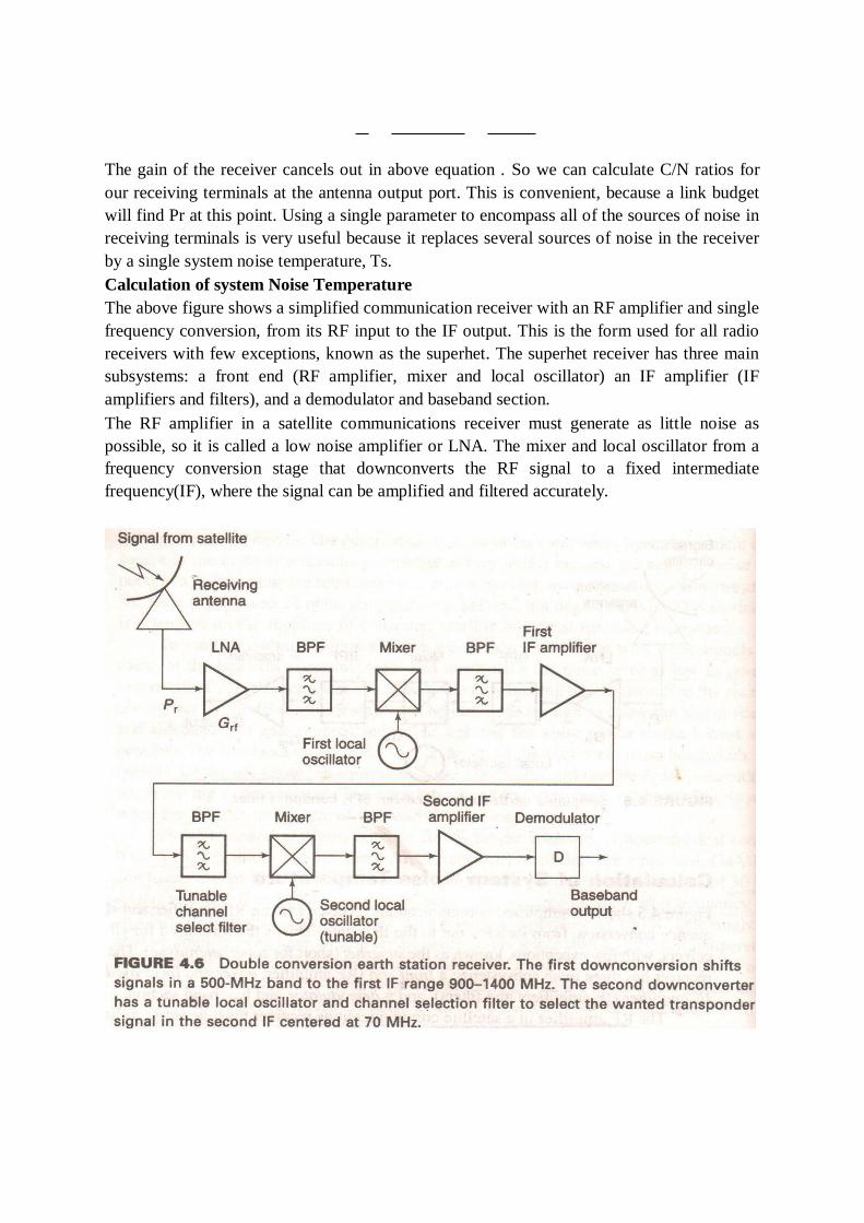
The gain of the receiver cancels out in above equation . So we can calculate C/N ratios for
our receiving terminals at the antenna output port. This is convenient, because a link budget
will find Pr at this point. Using a single parameter to encompass all of the sources of noise in
receiving terminals is very useful because it replaces several sources of noise in the receiver
by a single system noise temperature, Ts.
Calculation of system Noise Temperature
The above figure shows a simplified communication receiver with an RF amplifier and single
frequency conversion, from its RF input to the IF output. This is the form used for all radio
receivers with few exceptions, known as the superhet. The superhet receiver has three main
subsystems: a front end (RF amplifier, mixer and local oscillator) an IF amplifier (IF
amplifiers and filters), and a demodulator and baseband section.
The RF amplifier in a satellite communications receiver must generate as little noise as
possible, so it is called a low noise amplifier or LNA. The mixer and local oscillator from a
frequency conversion stage that downconverts the RF signal to a fixed intermediate
frequency(IF), where the signal can be amplified and filtered accurately.
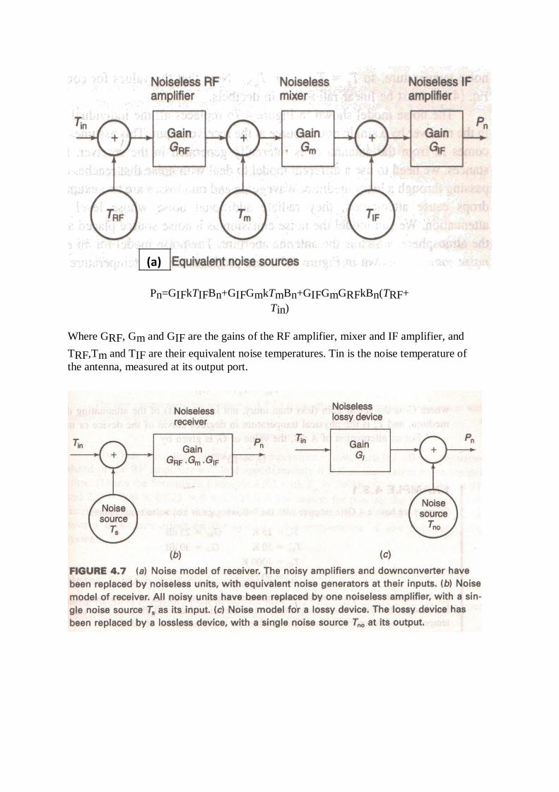
Pn=GIFkTIFBn+GIFGmkTmBn+GIFGmGRFkBn(TRF+
Tin)
Where GRF, Gm and GIF are the gains of the RF amplifier, mixer and IF amplifier, and
TRF,Tm and TIF are their equivalent noise temperatures. Tin is the noise temperature of
the antenna, measured at its output port.
(a)
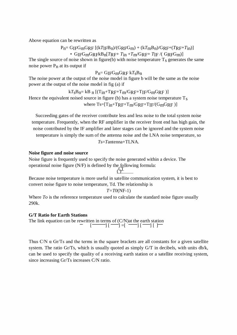
Above equation can be rewritten as
Pn= GIFGmGRF [(kTIFBn)/(GRFGm) + (kTmBn)/GRF+(TRF+Tin)]
• GIFGmGRFkBn[TRF+ Tin +Tm/GRF+ TIF /( GRFGm)]
The single source of noise shown in figure(b) with noise temperature Ts generates the same
noise power Pn at its output if
Pn= GIFGmGRF kTsBn
The noise power at the output of the noise model in figure b will be the same as the noise
power at the output of the noise model in fig (a) if
kTsBn= kB n [(Tin+TRF+Tm/GRF+TIF/GmGRF )]
Hence the equivalent noised source in figure (b) has a system noise temperature Ts
where Ts=[Tin+TRF+Tm/GRF+TIF/(GmGRF )]
Succeeding gates of the receiver contribute less and less noise to the total system noise
temperature. Frequently, when the RF amplifier in the receiver front end has high gain, the
noise contributed by the IF amplifier and later stages can be ignored and the system noise
temperature is simply the sum of the antenna noise and the LNA noise temperature, so
Ts=Tantenna+TLNA.
Noise figure and noise source
Noise figure is frequently used to specify the noise generated within a device. The
operational noise figure (N/F) is defined by the following formula: ( )
( )
Because noise temperature is more useful in satellite communication system, it is best to
convert noise figure to noise temperature, Td. The relationship is
T=T0(NF-1)
Where To is the reference temperature used to calculate the standard noise figure usually
290k.
G/T Ratio for Earth Stations
The link equation can be rewritten in terms of (C/N)at the earth station [ ] [ ] =[ ] [ ] [ ]
Thus C/N α Gr/Ts and the terms in the square brackets are all constants for a given satellite
system. The ratio Gr/Ts, which is usually quoted as simply G/T in decibels, with units db/k,
can be used to specify the quality of a receiving earth station or a satellite receiving system,
since increasing Gr/Ts increases C/N ratio.
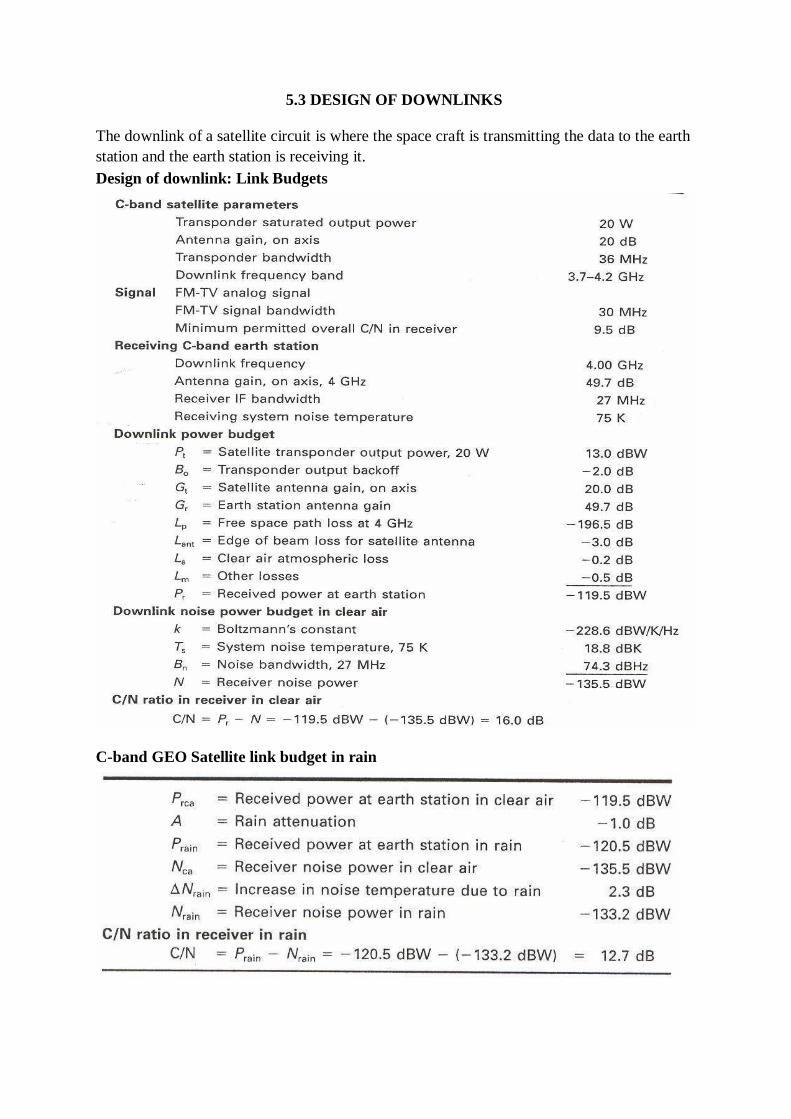
5.3 DESIGN OF DOWNLINKS
The downlink of a satellite circuit is where the space craft is transmitting the data to the earth
station and the earth station is receiving it.
Design of downlink: Link Budgets
C-band GEO Satellite link budget in rain
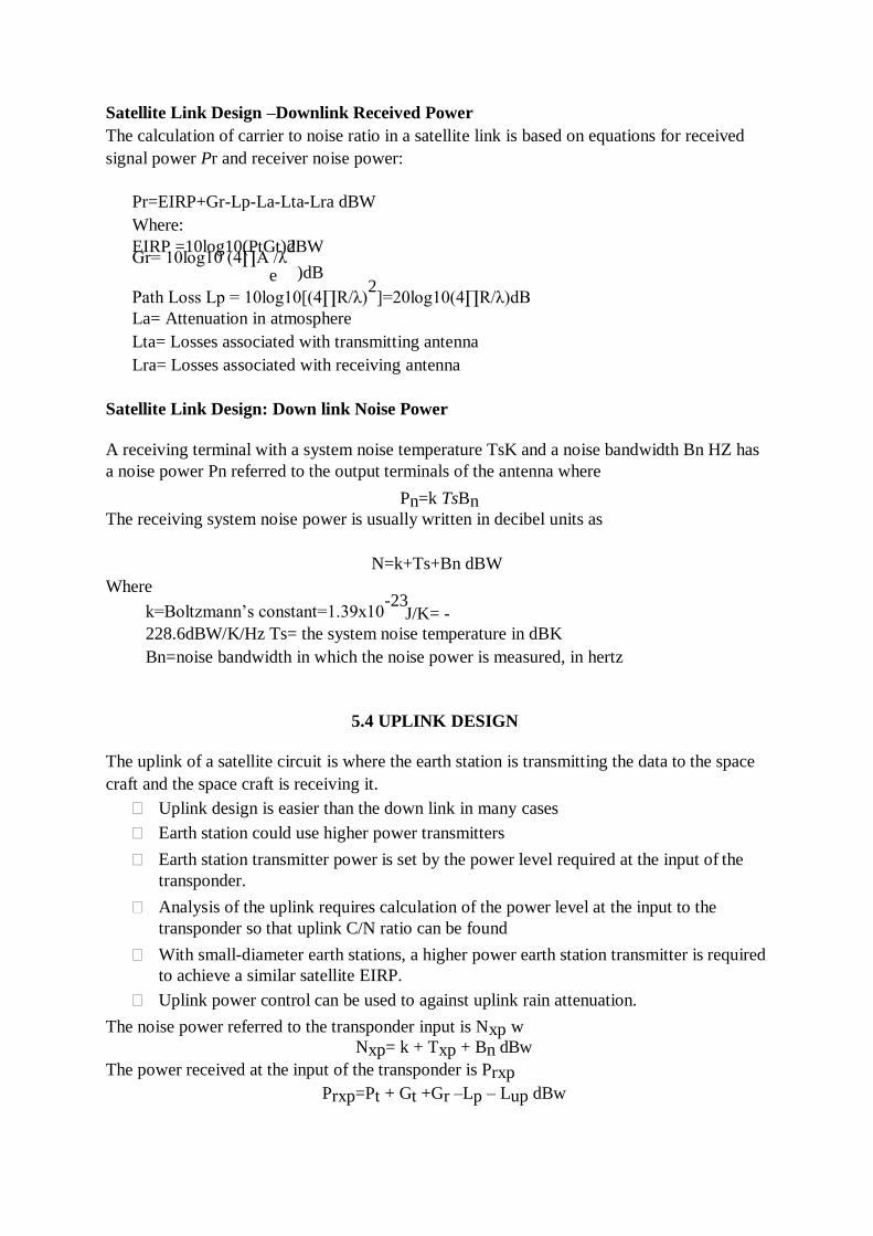
Satellite Link Design –Downlink Received Power
The calculation of carrier to noise ratio in a satellite link is based on equations for received
signal power Pr and receiver noise power:
Pr=EIRP+Gr-Lp-La-Lta-Lra dBW
Where:
EIRP =10log10(PtGt)dBW Gr= 10log10 (4∏A /λ
2
e )dB
Path Loss Lp = 10log10[(4∏R/λ)2]=20log10(4∏R/λ)dB
La= Attenuation in atmosphere
Lta= Losses associated with transmitting antenna
Lra= Losses associated with receiving antenna
Satellite Link Design: Down link Noise Power
A receiving terminal with a system noise temperature TsK and a noise bandwidth Bn HZ has
a noise power Pn referred to the output terminals of the antenna where
Pn=k TsBn
The receiving system noise power is usually written in decibel units as
N=k+Ts+Bn dBW
Where
k=Boltzmann‘s constant=1.39x10⁻²³
228.6dBW/K/Hz Ts= the system noise temperature in dBK
Bn=noise bandwidth in which the noise power is measured, in hertz
5.4 UPLINK DESIGN
The uplink of a satellite circuit is where the earth station is transmitting the data to the space
craft and the space craft is receiving it.
Uplink design is easier than the down link in many cases
Earth station could use higher power transmitters
Earth station transmitter power is set by the power level required at the input of the
transponder.
Analysis of the uplink requires calculation of the power level at the input to the
transponder so that uplink C/N ratio can be found
With small-diameter earth stations, a higher power earth station transmitter is required
to achieve a similar satellite EIRP.
Uplink power control can be used to against uplink rain attenuation.
The noise power referred to the transponder input is Nxp w
Nxp= k + Txp + Bn dBw
The power received at the input of the transponder is Prxp
Prxp=Pt + Gt +Gr –Lp – Lup dBw
J/K= -
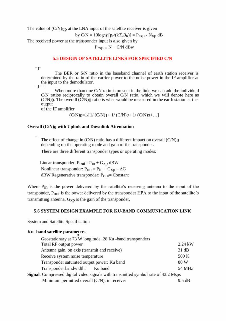
The value of (C/N)up at the LNA input of the satellite receiver is given
by C/N = 10log10[pr/(kTsBn)] = Prxp - Nxp dB
The received power at the transponder input is also given by
Prxp = N + C/N dBw
5.5 DESIGN OF SATELLITE LINKS FOR SPECIFIED C/N
The BER or S/N ratio in the baseband channel of earth station receiver is determined by the ratio of the carrier power to the noise power in the IF amplifier at the input to the demodulator.
When more than one C/N ratio is present in the link, we can add the individual
C/N ratios reciprocally to obtain overall C/N ratio, which we will denote here as (C/N)0. The overall (C/N)0 ratio is what would be measured in the earth station at the output of the IF amplifier
(C/N)0=1/[1/ (C/N)1+ 1/ (C/N)2+ 1/ (C/N)3+…]
Overall (C/N)0 with Uplink and Downlink Attenuation
The effect of change in (C/N) ratio has a different impact on overall (C/N)0 depending on the operating mode and gain of the transponder.
There are three different transponder types or operating modes:
Linear transponder: Pout= Pin + Gxp dBW
Nonlinear transponder: Pout= Pin + Gxp – ∆G
dBW Regenerative transponder: Pout= Constant
Where Pin is the power delivered by the satellite‘s receiving antenna to the input of the
transponder, Pout is the power delivered by the transponder HPA to the input of the satellite‘s
transmitting antenna, Gxp is the gain of the transponder.
5.6 SYSTEM DESIGN EXAMPLE FOR KU-BAND COMMUNICATION LINK
System and Satellite Specification
Ku -band satellite parameters
o Geostationary at 73 W longitude. 28 Ku -band transponders
Total RF output power 2.24 kW
Antenna gain, on axis (transmit and receive) 31 dB
Receive system noise temperature 500 K
Transponder saturated output power: Ku band 80 W
Transponder bandwidth: Ku band 54 MHz
Signal: Compressed digital video signals with transmitted symbol rate of 43.2 Msps
Minimum permitted overall (C/N), in receiver 9.5 dB
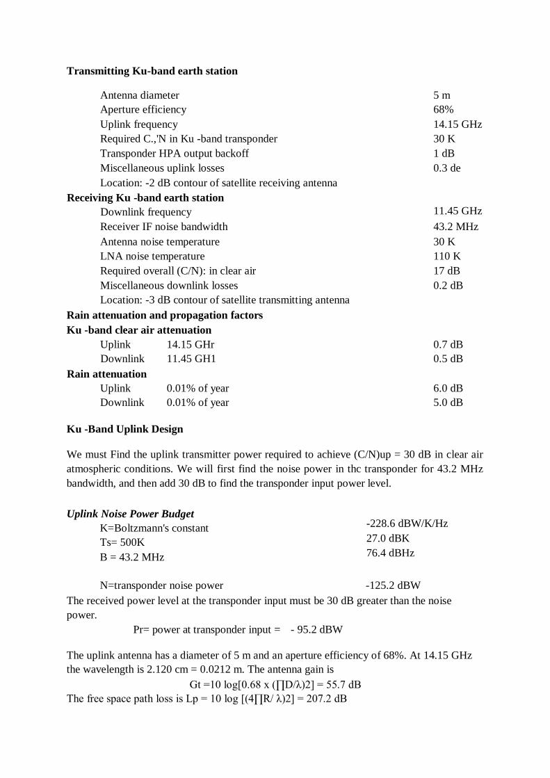
Transmitting Ku-band earth station
Antenna diameter 5 m
Aperture efficiency 68%
Uplink frequency 14.15 GHz
Required C.,'N in Ku -band transponder 30 K
Transponder HPA output backoff 1 dB
Miscellaneous uplink losses 0.3 de
Location: -2 dB contour of satellite receiving antenna
Receiving Ku -band earth station
Downlink frequency
11.45 GHz
Receiver IF noise bandwidth 43.2 MHz
Antenna noise temperature 30 K
LNA noise temperature 110 K
Required overall (C/N): in clear air 17 dB
Miscellaneous downlink losses 0.2 dB
Location: -3 dB contour of satellite transmitting antenna
Rain attenuation and propagation factors
Ku -band clear air attenuation
Uplink
Downlink
Rain attenuation
14.15 GHr
11.45 GH1
0.7 dB
0.5 dB
Uplink 0.01% of year 6.0 dB
Downlink 0.01% of year 5.0 dB
Ku -Band Uplink Design
We must Find the uplink transmitter power required to achieve (C/N)up = 30 dB in clear air
atmospheric conditions. We will first find the noise power in thc transponder for 43.2 MHz
bandwidth, and then add 30 dB to find the transponder input power level.
Uplink Noise Power Budget
K=Boltzmann's constant
Ts= 500K
B = 43.2 MHz
-228.6 dBW/K/Hz
27.0 dBK
76.4 dBHz
N=transponder noise power -125.2 dBW
The received power level at the transponder input must be 30 dB greater than the noise
power.
Pr= power at transponder input = - 95.2 dBW
The uplink antenna has a diameter of 5 m and an aperture efficiency of 68%. At 14.15 GHz
the wavelength is 2.120 cm = 0.0212 m. The antenna gain is
Gt =10 log[0.68 x (∏D/λ)2] = 55.7 dB
The free space path loss is Lp = 10 log [(4∏R/ λ)2] = 207.2 dB
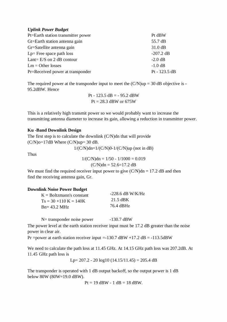
Uplink Power Budget Pt=Earth station transmitter power Pt dBW
Gt=Earth station antenna gain 55.7 dB
Gr=Satellite antenna gain 31.0 dB
Lp= Free space path loss -207.2 dB
Lant= E/S on 2 dB contour -2.0 dB
Lm = Other losses -1.0 dB
Pr=Received power at transponder Pt - 123.5 dB
The required power at the transponder input to meet the (C/N)up = 30 dB objective is -
95.2dBW. Hence
Pt - 123.5 dB = - 95.2 dBW
Pt = 28.3 dBW or 675W
This is a relatively high transmit power so we would probably want to increase the
transmitting antenna diameter to increase its gain, allowing a reduction in transmitter power.
Ku -Band Downlink Design
The first step is to calculate the downlink (C/N)dn that will provide
(C/N)o=17dB Where (C/N)up= 30 dB.
1/(C/N)dn=1/(C/N)0-1/(C/N)up (not in dB)
Thus
1/(C/N)dn = 1/50 - 1/1000 = 0.019
(C/N)dn = 52.6=17.2 dB
We must find the required receiver input power to give (C/N)dn = 17.2 dB and then
find the receiving antenna gain, Gr.
Downlink Noise Power Budget
K = Boltzmann's constant
Ts = 30 +110 K = 140K
Bn= 43.2 MHz
-228.6 dB W/K/Hz
21.5 dBK
76.4 dBHz
N= transponder noise power -130.7 dBW
The power level at the earth station receiver input must be 17.2 dB greater than the noise
power in clear air.
Pr =power at earth station receiver input =-130.7 dBW +17.2 dB = -113.5dBW
We need to calculate the path loss at 11.45 GHz. At 14.15 GHz path loss was 207.2dB. At
11.45 GHz path loss is
Lp= 207.2 - 20 log10 (14.15/11.45) = 205.4 dB
The transponder is operated with 1 dB output backoff, so the output power is 1 dB
below 80W (80W=19.0 dBW).
Pt = 19 dBW - 1 dB = 18 dBW.
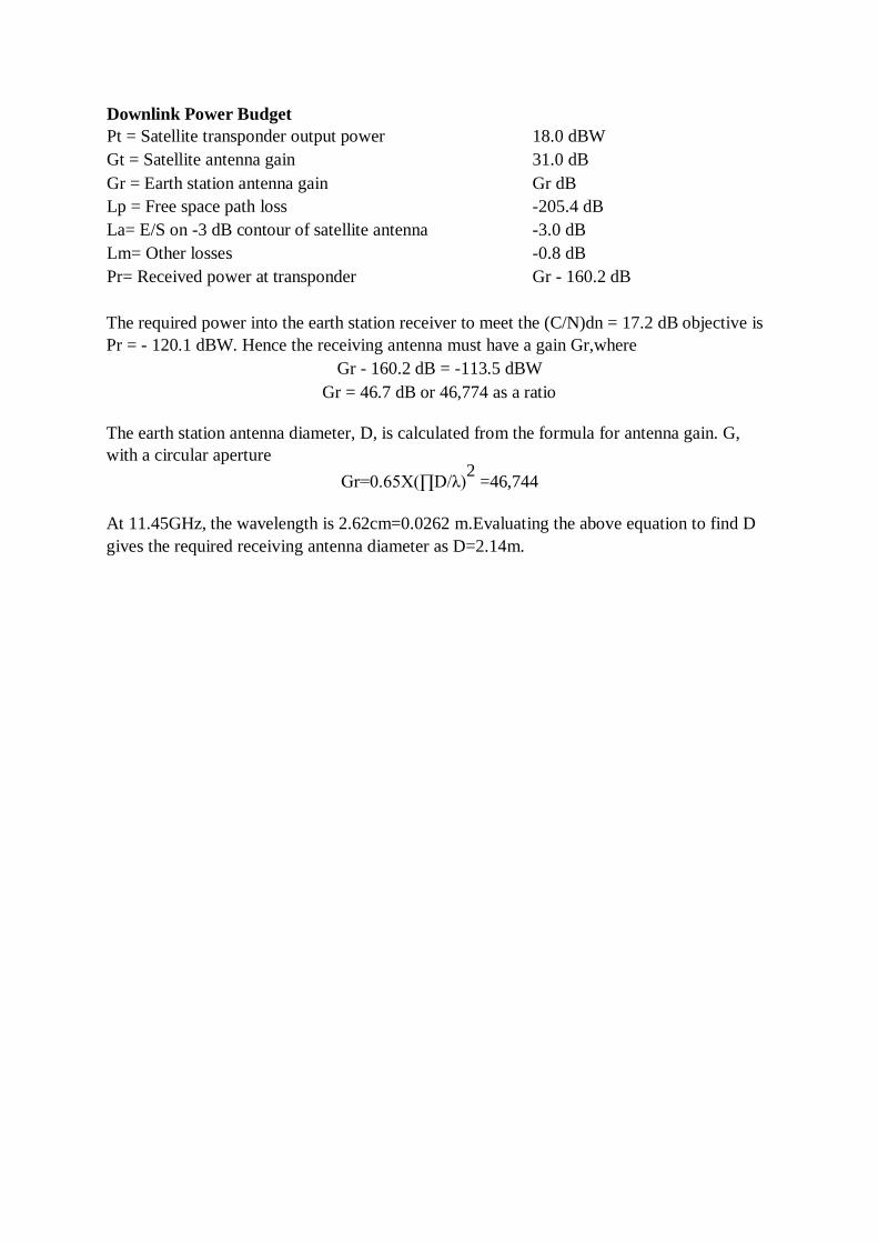
Downlink Power Budget Pt = Satellite transponder output power 18.0 dBW
Gt = Satellite antenna gain 31.0 dB
Gr = Earth station antenna gain Gr dB
Lp = Free space path loss -205.4 dB
La= E/S on -3 dB contour of satellite antenna -3.0 dB
Lm= Other losses -0.8 dB
Pr= Received power at transponder Gr - 160.2 dB
The required power into the earth station receiver to meet the (C/N)dn = 17.2 dB objective is
Pr = - 120.1 dBW. Hence the receiving antenna must have a gain Gr,where
Gr - 160.2 dB = -113.5 dBW
Gr = 46.7 dB or 46,774 as a ratio
The earth station antenna diameter, D, is calculated from the formula for antenna gain. G,
with a circular aperture
Gr=0.65X(∏D/λ)2
=46,744
At 11.45GHz, the wavelength is 2.62cm=0.0262 m.Evaluating the above equation to find D
gives the required receiving antenna diameter as D=2.14m.
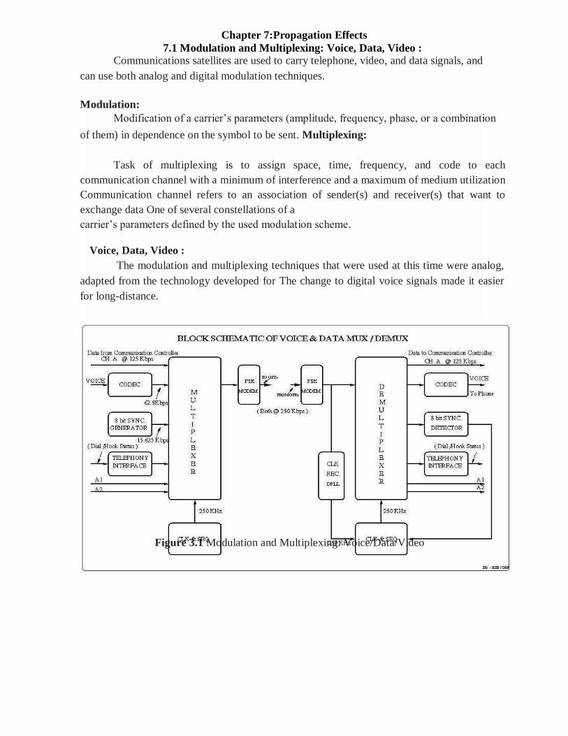
Chapter 7:Propagation Effects
7.1 Modulation and Multiplexing: Voice, Data, Video :
Communications satellites are used to carry telephone, video, and data signals, and
can use both analog and digital modulation techniques.
Modulation:
Modification of a carrier‘s parameters (amplitude, frequency, phase, or a combination
of them) in dependence on the symbol to be sent. Multiplexing:
Task of multiplexing is to assign space, time, frequency, and code to each
communication channel with a minimum of interference and a maximum of medium utilization
Communication channel refers to an association of sender(s) and receiver(s) that want to
exchange data One of several constellations of a
carrier‘s parameters defined by the used modulation scheme.
Voice, Data, Video :
The modulation and multiplexing techniques that were used at this time were analog,
adapted from the technology developed for The change to digital voice signals made it easier
for long-distance.
Figure 3.1 Modulation and Multiplexing: Voice/Data/Video
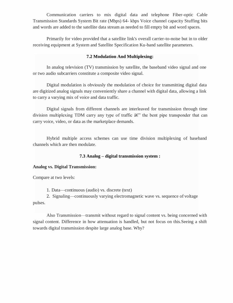
Communication carriers to mix digital data and telephone Fiber-optic Cable
Transmission Standards System Bit rate (Mbps) 64- kbps Voice channel capacity Stuffing bits
and words are added to the satellite data stream as needed to fill empty bit and word spaces.
Primarily for video provided that a satellite link's overall carrier-to-noise but in to older
receiving equipment at System and Satellite Specification Ku-band satellite parameters.
7.2 Modulation And Multiplexing:
In analog television (TV) transmission by satellite, the baseband video signal and one
or two audio subcarriers constitute a composite video signal.
Digital modulation is obviously the modulation of choice for transmitting digital data
are digitized analog signals may conveniently share a channel with digital data, allowing a link
to carry a varying mix of voice and data traffic.
Digital signals from different channels are interleaved for transmission through time
division multiplexing TDM carry any type of traffic â€‖ the bent pipe transponder that can
carry voice, video, or data as the marketplace demands.
Hybrid multiple access schemes can use time division multiplexing of baseband
channels which are then modulate.
7.3 Analog – digital transmission system :
Analog vs. Digital Transmission:
Compare at two levels:
1. Data—continuous (audio) vs. discrete (text)
2. Signaling—continuously varying electromagnetic wave vs. sequence of voltage
pulses.
Also Transmission—transmit without regard to signal content vs. being concerned with
signal content. Difference in how attenuation is handled, but not focus on this.Seeing a shift
towards digital transmission despite large analog base. Why?
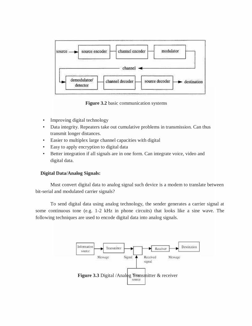
Figure 3.2 basic communication systems
• Improving digital technology
• Data integrity. Repeaters take out cumulative problems in transmission. Can thus
transmit longer distances.
• Easier to multiplex large channel capacities with digital
• Easy to apply encryption to digital data
• Better integration if all signals are in one form. Can integrate voice, video and
digital data.
Digital Data/Analog Signals:
Must convert digital data to analog signal such device is a modem to translate between
bit-serial and modulated carrier signals?
To send digital data using analog technology, the sender generates a carrier signal at
some continuous tone (e.g. 1-2 kHz in phone circuits) that looks like a sine wave. The
following techniques are used to encode digital data into analog signals.
Figure 3.3 Digital /Analog Transmitter & receiver
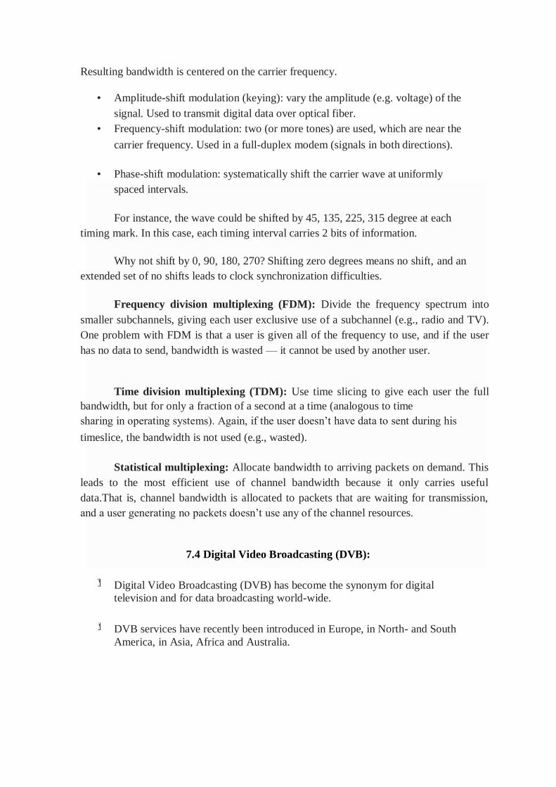
Resulting bandwidth is centered on the carrier frequency.
• Amplitude-shift modulation (keying): vary the amplitude (e.g. voltage) of the
signal. Used to transmit digital data over optical fiber.
• Frequency-shift modulation: two (or more tones) are used, which are near the
carrier frequency. Used in a full-duplex modem (signals in both directions).
• Phase-shift modulation: systematically shift the carrier wave at uniformly
spaced intervals.
For instance, the wave could be shifted by 45, 135, 225, 315 degree at each
timing mark. In this case, each timing interval carries 2 bits of information.
Why not shift by 0, 90, 180, 270? Shifting zero degrees means no shift, and an
extended set of no shifts leads to clock synchronization difficulties.
Frequency division multiplexing (FDM): Divide the frequency spectrum into
smaller subchannels, giving each user exclusive use of a subchannel (e.g., radio and TV).
One problem with FDM is that a user is given all of the frequency to use, and if the user
has no data to send, bandwidth is wasted — it cannot be used by another user.
Time division multiplexing (TDM): Use time slicing to give each user the full
bandwidth, but for only a fraction of a second at a time (analogous to time
sharing in operating systems). Again, if the user doesn‘t have data to sent during his
timeslice, the bandwidth is not used (e.g., wasted).
Statistical multiplexing: Allocate bandwidth to arriving packets on demand. This
leads to the most efficient use of channel bandwidth because it only carries useful
data.That is, channel bandwidth is allocated to packets that are waiting for transmission,
and a user generating no packets doesn‘t use any of the channel resources.
7.4 Digital Video Broadcasting (DVB):
Digital Video Broadcasting (DVB) has become the synonym for digital
television and for data broadcasting world-wide.
DVB services have recently been introduced in Europe, in North- and South
America, in Asia, Africa and Australia.
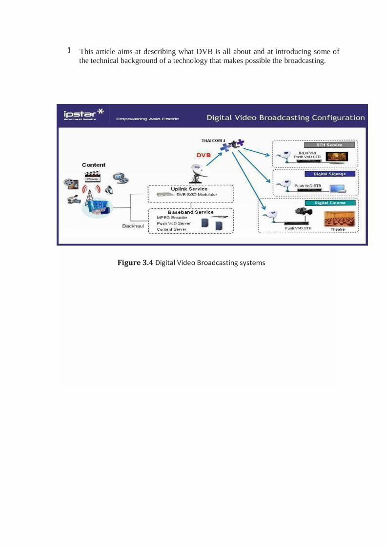
This article aims at describing what DVB is all about and at introducing some of
the technical background of a technology that makes possible the broadcasting.
Figure 3.4 Digital Video Broadcasting systems
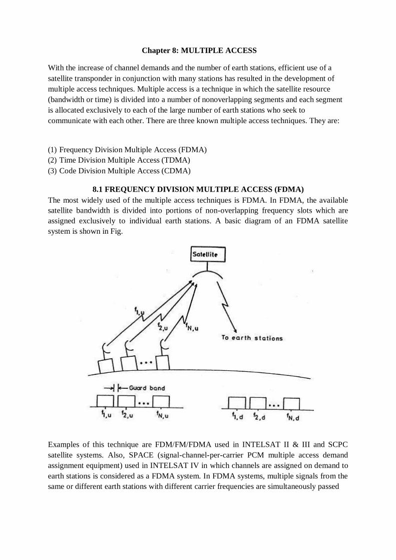
Chapter 8: MULTIPLE ACCESS
With the increase of channel demands and the number of earth stations, efficient use of a
satellite transponder in conjunction with many stations has resulted in the development of
multiple access techniques. Multiple access is a technique in which the satellite resource
(bandwidth or time) is divided into a number of nonoverlapping segments and each segment
is allocated exclusively to each of the large number of earth stations who seek to
communicate with each other. There are three known multiple access techniques. They are:
(1) Frequency Division Multiple Access (FDMA)
(2) Time Division Multiple Access (TDMA)
(3) Code Division Multiple Access (CDMA)
8.1 FREQUENCY DIVISION MULTIPLE ACCESS (FDMA)
The most widely used of the multiple access techniques is FDMA. In FDMA, the available
satellite bandwidth is divided into portions of non-overlapping frequency slots which are
assigned exclusively to individual earth stations. A basic diagram of an FDMA satellite
system is shown in Fig.
Examples of this technique are FDM/FM/FDMA used in INTELSAT II & III and SCPC
satellite systems. Also, SPACE (signal-channel-per-carrier PCM multiple access demand
assignment equipment) used in INTELSAT IV in which channels are assigned on demand to
earth stations is considered as a FDMA system. In FDMA systems, multiple signals from the
same or different earth stations with different carrier frequencies are simultaneously passed
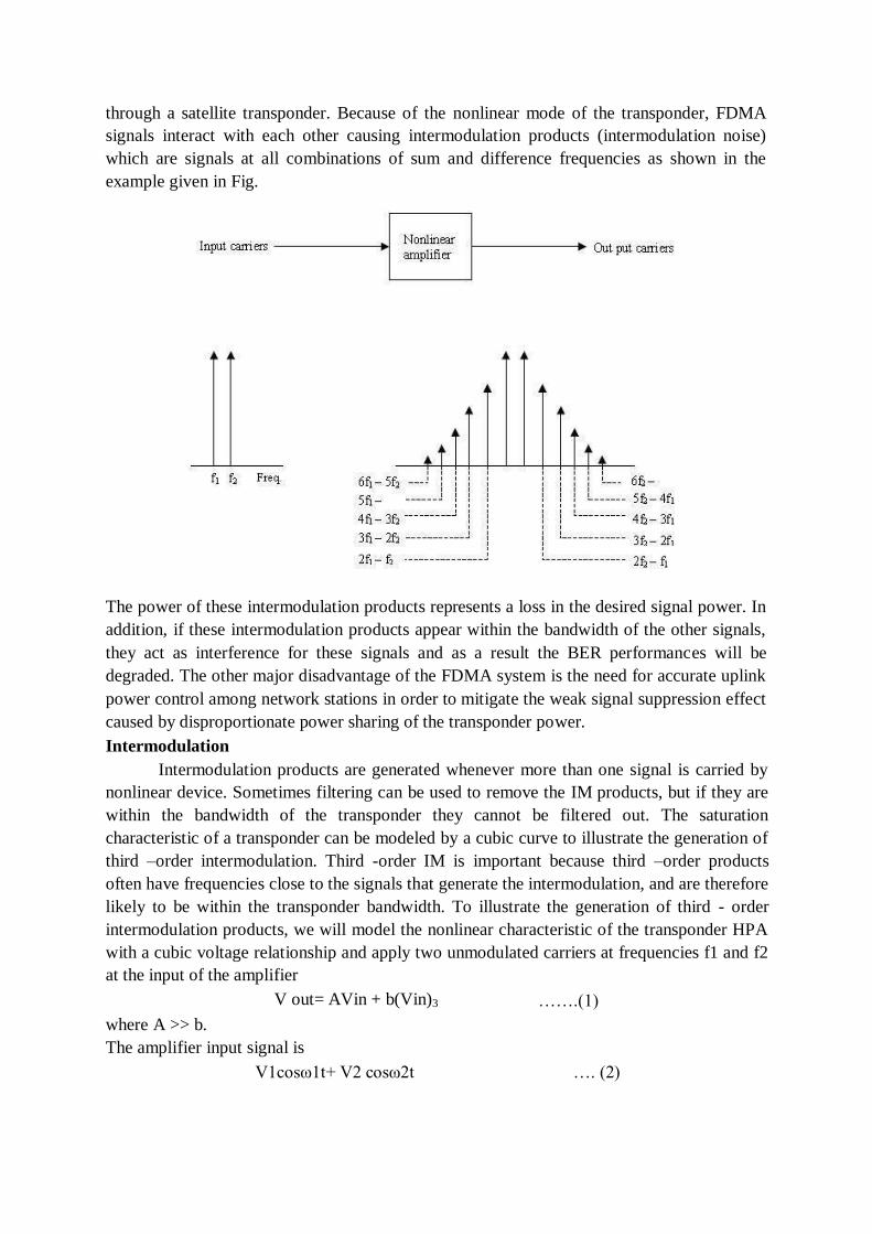
through a satellite transponder. Because of the nonlinear mode of the transponder, FDMA
signals interact with each other causing intermodulation products (intermodulation noise)
which are signals at all combinations of sum and difference frequencies as shown in the
example given in Fig.
The power of these intermodulation products represents a loss in the desired signal power. In
addition, if these intermodulation products appear within the bandwidth of the other signals,
they act as interference for these signals and as a result the BER performances will be
degraded. The other major disadvantage of the FDMA system is the need for accurate uplink
power control among network stations in order to mitigate the weak signal suppression effect
caused by disproportionate power sharing of the transponder power.
Intermodulation
Intermodulation products are generated whenever more than one signal is carried by
nonlinear device. Sometimes filtering can be used to remove the IM products, but if they are
within the bandwidth of the transponder they cannot be filtered out. The saturation
characteristic of a transponder can be modeled by a cubic curve to illustrate the generation of
third –order intermodulation. Third -order IM is important because third –order products
often have frequencies close to the signals that generate the intermodulation, and are therefore
likely to be within the transponder bandwidth. To illustrate the generation of third - order
intermodulation products, we will model the nonlinear characteristic of the transponder HPA
with a cubic voltage relationship and apply two unmodulated carriers at frequencies f1 and f2
at the input of the amplifier
V out= AVin + b(Vin)3 …….(1)
where A >> b.
The amplifier input signal is
V1cosω1t+ V2 cosω2t …. (2)
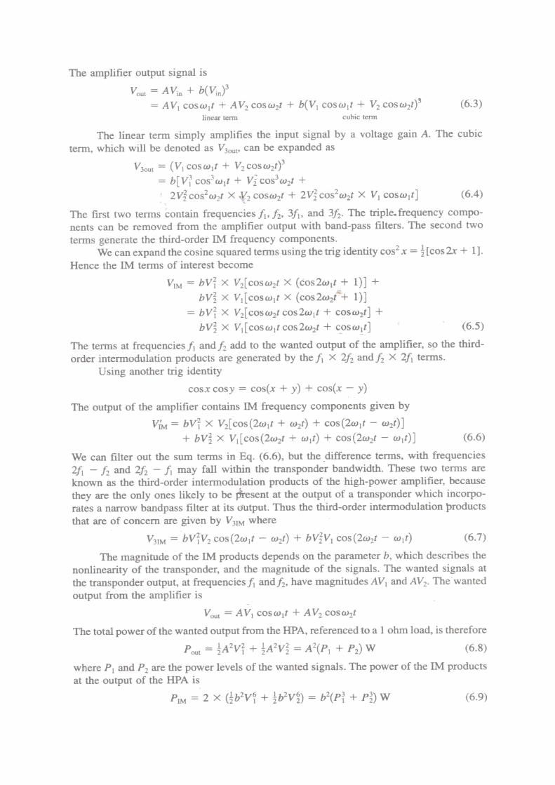
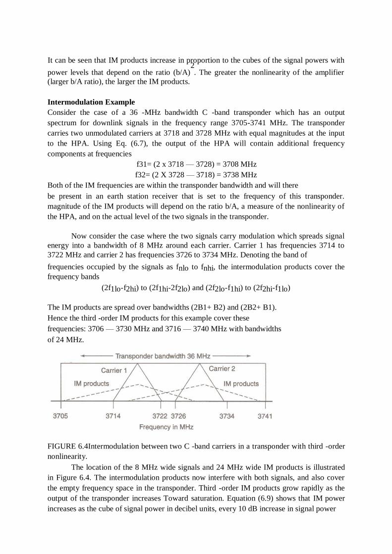
It can be seen that IM products increase in proportion to the cubes of the signal powers with 2
power levels that depend on the ratio (b/A) . The greater the nonlinearity of the amplifier
(larger b/A ratio), the larger the IM products.
Intermodulation Example
Consider the case of a 36 -MHz bandwidth C -band transponder which has an output
spectrum for downlink signals in the frequency range 3705-3741 MHz. The transponder
carries two unmodulated carriers at 3718 and 3728 MHz with equal magnitudes at the input
to the HPA. Using Eq. (6.7), the output of the HPA will contain additional frequency
components at frequencies
f31= (2 x 3718 — 3728) = 3708 MHz
f32= (2 X 3728 — 3718) = 3738 MHz
Both of the IM frequencies are within the transponder bandwidth and will there
be present in an earth station receiver that is set to the frequency of this transponder.
magnitude of the IM products will depend on the ratio b/A, a measure of the nonlinearity of
the HPA, and on the actual level of the two signals in the transponder.
Now consider the case where the two signals carry modulation which spreads signal
energy into a bandwidth of 8 MHz around each carrier. Carrier 1 has frequencies 3714 to
3722 MHz and carrier 2 has frequencies 3726 to 3734 MHz. Denoting the band of
frequencies occupied by the signals as fnlo to fnhi, the intermodulation products cover the
frequency bands
(2f1lo-f2hi) to (2f1hi-2f2lo) and (2f2lo-f1hi) to (2f2hi-f1lo)
The IM products are spread over bandwidths (2B1+ B2) and (2B2+ B1).
Hence the third -order IM products for this example cover these
frequencies: 3706 — 3730 MHz and 3716 — 3740 MHz with bandwidths
of 24 MHz.
FIGURE 6.4Intermodulation between two C -band carriers in a transponder with third -order
nonlinearity.
The location of the 8 MHz wide signals and 24 MHz wide IM products is illustrated
in Figure 6.4. The intermodulation products now interfere with both signals, and also cover
the empty frequency space in the transponder. Third -order IM products grow rapidly as the
output of the transponder increases Toward saturation. Equation (6.9) shows that IM power
increases as the cube of signal power in decibel units, every 10 dB increase in signal power
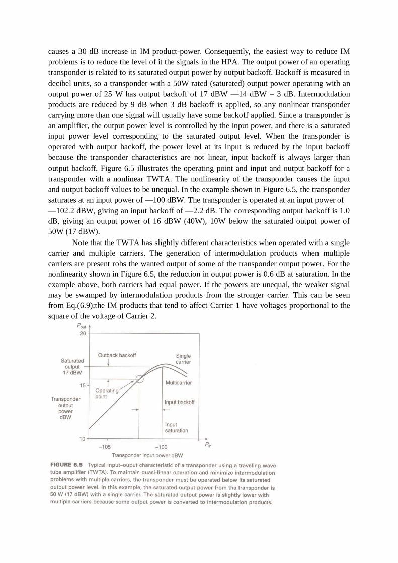
causes a 30 dB increase in IM product-power. Consequently, the easiest way to reduce IM
problems is to reduce the level of it the signals in the HPA. The output power of an operating
transponder is related to its saturated output power by output backoff. Backoff is measured in
decibel units, so a transponder with a 50W rated (saturated) output power operating with an
output power of 25 W has output backoff of 17 dBW —14 dBW = 3 dB. Intermodulation
products are reduced by 9 dB when 3 dB backoff is applied, so any nonlinear transponder
carrying more than one signal will usually have some backoff applied. Since a transponder is
an amplifier, the output power level is controlled by the input power, and there is a saturated
input power level corresponding to the saturated output level. When the transponder is
operated with output backoff, the power level at its input is reduced by the input backoff
because the transponder characteristics are not linear, input backoff is always larger than
output backoff. Figure 6.5 illustrates the operating point and input and output backoff for a
transponder with a nonlinear TWTA. The nonlinearity of the transponder causes the input
and output backoff values to be unequal. In the example shown in Figure 6.5, the transponder
saturates at an input power of —100 dBW. The transponder is operated at an input power of
—102.2 dBW, giving an input backoff of —2.2 dB. The corresponding output backoff is 1.0
dB, giving an output power of 16 dBW (40W), 10W below the saturated output power of
50W (17 dBW).
Note that the TWTA has slightly different characteristics when operated with a single
carrier and multiple carriers. The generation of intermodulation products when multiple
carriers are present robs the wanted output of some of the transponder output power. For the
nonlinearity shown in Figure 6.5, the reduction in output power is 0.6 dB at saturation. In the
example above, both carriers had equal power. If the powers are unequal, the weaker signal
may be swamped by intermodulation products from the stronger carrier. This can be seen
from Eq.(6.9);the IM products that tend to affect Carrier 1 have voltages proportional to the
square of the voltage of Carrier 2.
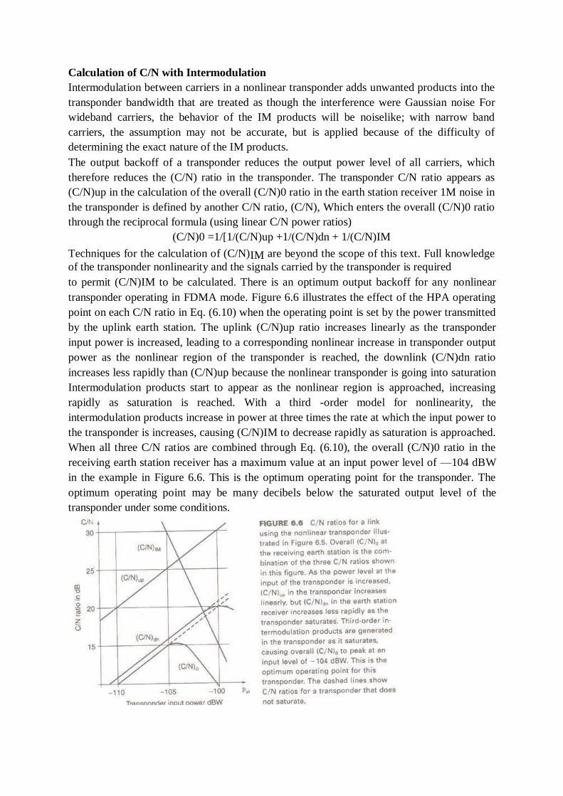
Calculation of C/N with Intermodulation
Intermodulation between carriers in a nonlinear transponder adds unwanted products into the
transponder bandwidth that are treated as though the interference were Gaussian noise For
wideband carriers, the behavior of the IM products will be noiselike; with narrow band
carriers, the assumption may not be accurate, but is applied because of the difficulty of
determining the exact nature of the IM products.
The output backoff of a transponder reduces the output power level of all carriers, which
therefore reduces the (C/N) ratio in the transponder. The transponder C/N ratio appears as
(C/N)up in the calculation of the overall (C/N)0 ratio in the earth station receiver 1M noise in
the transponder is defined by another C/N ratio, (C/N), Which enters the overall (C/N)0 ratio
through the reciprocal formula (using linear C/N power ratios)
(C/N)0 =1/[1/(C/N)up +1/(C/N)dn + 1/(C/N)IM
Techniques for the calculation of (C/N)IM are beyond the scope of this text. Full knowledge
of the transponder nonlinearity and the signals carried by the transponder is required
to permit (C/N)IM to be calculated. There is an optimum output backoff for any nonlinear
transponder operating in FDMA mode. Figure 6.6 illustrates the effect of the HPA operating
point on each C/N ratio in Eq. (6.10) when the operating point is set by the power transmitted
by the uplink earth station. The uplink (C/N)up ratio increases linearly as the transponder
input power is increased, leading to a corresponding nonlinear increase in transponder output
power as the nonlinear region of the transponder is reached, the downlink (C/N)dn ratio
increases less rapidly than (C/N)up because the nonlinear transponder is going into saturation
Intermodulation products start to appear as the nonlinear region is approached, increasing
rapidly as saturation is reached. With a third -order model for nonlinearity, the
intermodulation products increase in power at three times the rate at which the input power to
the transponder is increases, causing (C/N)IM to decrease rapidly as saturation is approached.
When all three C/N ratios are combined through Eq. (6.10), the overall (C/N)0 ratio in the
receiving earth station receiver has a maximum value at an input power level of —104 dBW
in the example in Figure 6.6. This is the optimum operating point for the transponder. The
optimum operating point may be many decibels below the saturated output level of the
transponder under some conditions.
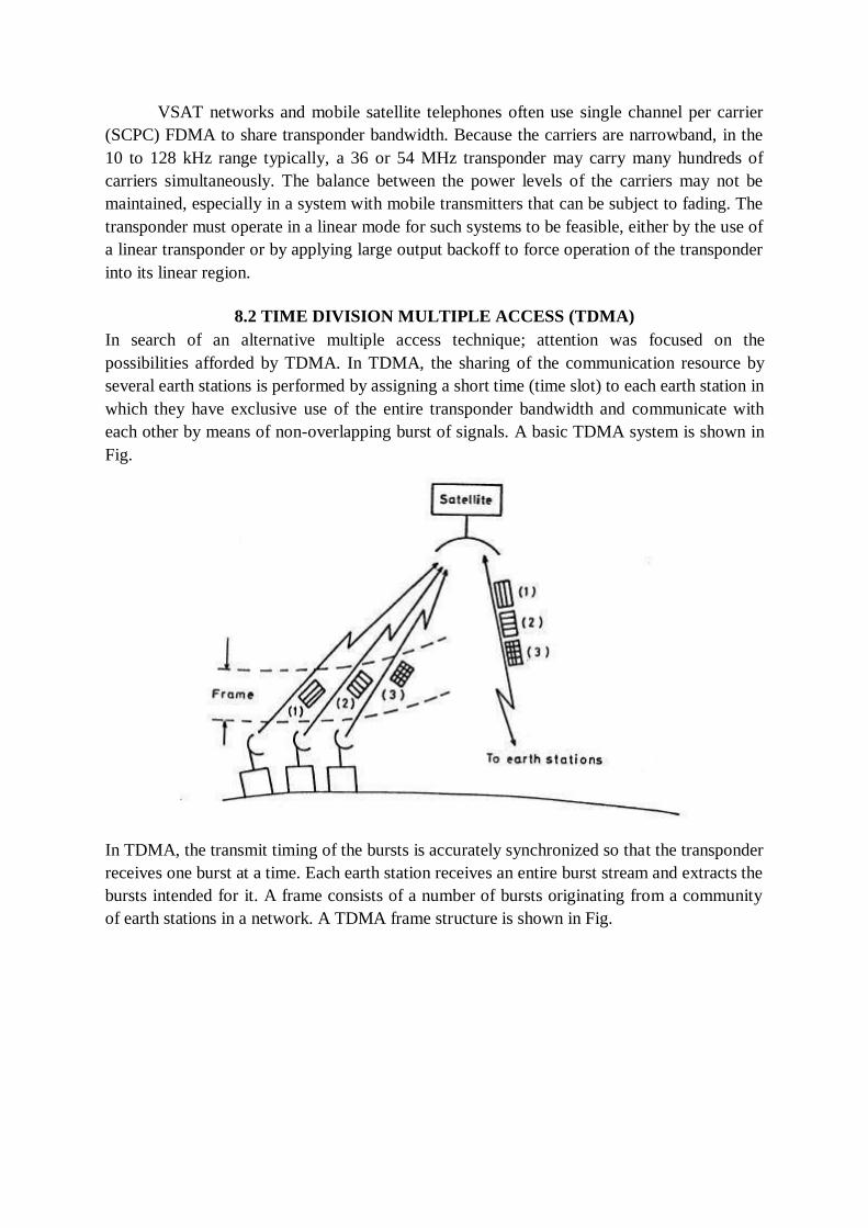
VSAT networks and mobile satellite telephones often use single channel per carrier
(SCPC) FDMA to share transponder bandwidth. Because the carriers are narrowband, in the
10 to 128 kHz range typically, a 36 or 54 MHz transponder may carry many hundreds of
carriers simultaneously. The balance between the power levels of the carriers may not be
maintained, especially in a system with mobile transmitters that can be subject to fading. The
transponder must operate in a linear mode for such systems to be feasible, either by the use of
a linear transponder or by applying large output backoff to force operation of the transponder
into its linear region.
8.2 TIME DIVISION MULTIPLE ACCESS (TDMA)
In search of an alternative multiple access technique; attention was focused on the
possibilities afforded by TDMA. In TDMA, the sharing of the communication resource by
several earth stations is performed by assigning a short time (time slot) to each earth station in
which they have exclusive use of the entire transponder bandwidth and communicate with
each other by means of non-overlapping burst of signals. A basic TDMA system is shown in
Fig.
In TDMA, the transmit timing of the bursts is accurately synchronized so that the transponder
receives one burst at a time. Each earth station receives an entire burst stream and extracts the
bursts intended for it. A frame consists of a number of bursts originating from a community
of earth stations in a network. A TDMA frame structure is shown in Fig.
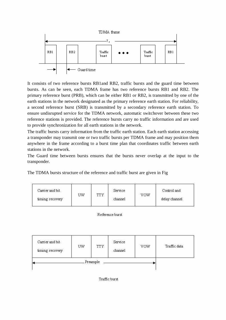
It consists of two reference bursts RB1and RB2, traffic bursts and the guard time between
bursts. As can be seen, each TDMA frame has two reference bursts RB1 and RB2. The
primary reference burst (PRB), which can be either RB1 or RB2, is transmitted by one of the
earth stations in the network designated as the primary reference earth station. For reliability,
a second reference burst (SRB) is transmitted by a secondary reference earth station. To
ensure undisrupted service for the TDMA network, automatic switchover between these two
reference stations is provided. The reference bursts carry no traffic information and are used
to provide synchronization for all earth stations in the network.
The traffic bursts carry information from the traffic earth station. Each earth station accessing
a transponder may transmit one or two traffic bursts per TDMA frame and may position them
anywhere in the frame according to a burst time plan that coordinates traffic between earth
stations in the network.
The Guard time between bursts ensures that the bursts never overlap at the input to the
transponder.
The TDMA bursts structure of the reference and traffic burst are given in Fig
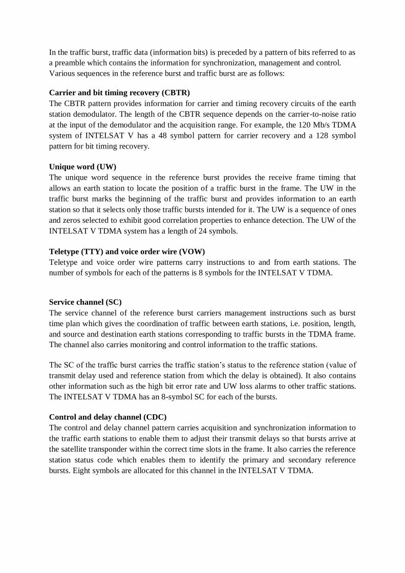
In the traffic burst, traffic data (information bits) is preceded by a pattern of bits referred to as
a preamble which contains the information for synchronization, management and control.
Various sequences in the reference burst and traffic burst are as follows:
Carrier and bit timing recovery (CBTR)
The CBTR pattern provides information for carrier and timing recovery circuits of the earth
station demodulator. The length of the CBTR sequence depends on the carrier-to-noise ratio
at the input of the demodulator and the acquisition range. For example, the 120 Mb/s TDMA
system of INTELSAT V has a 48 symbol pattern for carrier recovery and a 128 symbol
pattern for bit timing recovery.
Unique word (UW)
The unique word sequence in the reference burst provides the receive frame timing that
allows an earth station to locate the position of a traffic burst in the frame. The UW in the
traffic burst marks the beginning of the traffic burst and provides information to an earth
station so that it selects only those traffic bursts intended for it. The UW is a sequence of ones
and zeros selected to exhibit good correlation properties to enhance detection. The UW of the
INTELSAT V TDMA system has a length of 24 symbols.
Teletype (TTY) and voice order wire (VOW)
Teletype and voice order wire patterns carry instructions to and from earth stations. The
number of symbols for each of the patterns is 8 symbols for the INTELSAT V TDMA.
Service channel (SC)
The service channel of the reference burst carriers management instructions such as burst
time plan which gives the coordination of traffic between earth stations, i.e. position, length,
and source and destination earth stations corresponding to traffic bursts in the TDMA frame.
The channel also carries monitoring and control information to the traffic stations.
The SC of the traffic burst carries the traffic station‘s status to the reference station (value of
transmit delay used and reference station from which the delay is obtained). It also contains
other information such as the high bit error rate and UW loss alarms to other traffic stations.
The INTELSAT V TDMA has an 8-symbol SC for each of the bursts.
Control and delay channel (CDC)
The control and delay channel pattern carries acquisition and synchronization information to
the traffic earth stations to enable them to adjust their transmit delays so that bursts arrive at
the satellite transponder within the correct time slots in the frame. It also carries the reference
station status code which enables them to identify the primary and secondary reference
bursts. Eight symbols are allocated for this channel in the INTELSAT V TDMA.
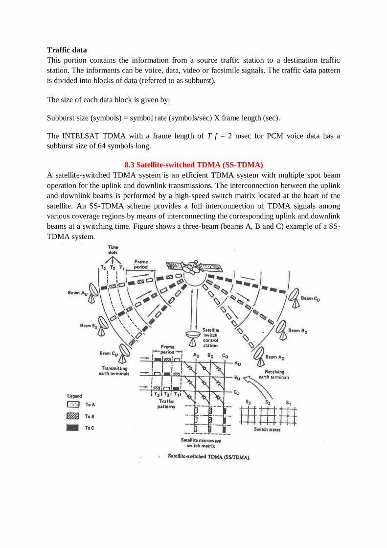
Traffic data
This portion contains the information from a source traffic station to a destination traffic
station. The informants can be voice, data, video or facsimile signals. The traffic data pattern
is divided into blocks of data (referred to as subburst).
The size of each data block is given by:
Subburst size (symbols) = symbol rate (symbols/sec) X frame length (sec).
The INTELSAT TDMA with a frame length of T f = 2 msec for PCM voice data has a
subburst size of 64 symbols long.
8.3 Satellite-switched TDMA (SS-TDMA)
A satellite-switched TDMA system is an efficient TDMA system with multiple spot beam
operation for the uplink and downlink transmissions. The interconnection between the uplink
and downlink beams is performed by a high-speed switch matrix located at the heart of the
satellite. An SS-TDMA scheme provides a full interconnection of TDMA signals among
various coverage regions by means of interconnecting the corresponding uplink and downlink
beams at a switching time. Figure shows a three-beam (beams A, B and C) example of a SS-
TDMA system.
The switch matrix is configured in a crossbar design in which only a single row is connected
to a single column at a time. In this figure, three different traffic patterns during time slot
intervals T1, T2 and T3, with three different switch states s1, s2 and s3 are also shown. The
switching sequence is programmed via a ground control so that states can be changed from
time to time. The advantages of SS-TDMA systems over TDMA systems are:
(1) The possibility of frequency re-use by spot-beam spatial discrimination, i.e. the same
frequency band can be spatially re-used many times. Hence, a considerable increase in
satellite capacity can be made.
(2) The use of a narrow antenna beam which provides a high gain for the coverage region.
Hence, a power saving can be obtained in both the uplink and downlink. An SS-TDMA
scheme has been planned for INTELSAT VI and Olympus satellites.
Satellite Switched TDMA
One advantage that TDMA has when used with a baseband processing transponder is satellite
switched TDMA. Instead of using a single antenna beam to maintain continuous
communication with its entire coverage zone, the satellite has a number of narrow antenna
beams that -can be used sequentially to cover the zone. A narrow antenna beam has a high
gain than a broad beam, which increases the satellite EIRP and therefore increases the
capacity of the downlink. Uplink signals received by the satellite are demodulated to recover
the bit streams, which are structured as a sequence of packets addressed to different receiving
earth stations. The satellite creates TDMA frames of data that contain packets addressed to
specific earth stations, and switches its transmit beam to the direction of the receiving earth
station as the packets are transmitted. Note that control of the TDMA network timing could
now be on board the satellite, rather than at a master earth station.
8.4 ONBOARD PROCESSING
The discussion of multiple access so far has assumed the use of a bent pipe transponder.
which simply amplifies a signal received from earth and retransmits it back to earth at a
different frequency. The advantage of a bent pipe transponder is flexibility. The transponder
can be used for any combination of signals that will fit within its bandwidth. The
disadvantage of the bent pipe transponder is that it is not well suited to uplinks from small
earth stations, especially uplinks operating in Ka band. Consider a link between a same
transmitting earth station and a large hub station via a bent pipe GEO satellite transponder.
There will usually be a small rain fade margin on the uplink from the transmitting station
because of its low EIRP. When rain affects the uplink, the C/N ratio in the transponder will
fall. The overall C/N ratio in the hub station receiver cannot be greater than the C/N ratio in
the transponder, so the bit error rate at the hub station will increase quickly as rain affects the
uplink. The only available solution is to use forward error correction coding on the link,
which lowers the data throughput but is actually needed for less than 5% of the time. The
problem of uplink attenuation in rain is most severe for 30/20 GHz uplinks with small
margins. Outages are likely to be frequent unless a large rain fade margin is included- in the
uplink power budget. Onboard processing or a baseband processing transponder can
overcome this problem by separating the uplink and downlink signals and their C/N ratios.
The baseband processing transponder can also have different modulation schemes on the
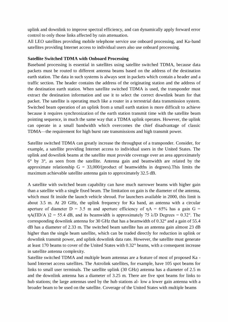
uplink and downlink to improve spectral efficiency, and can dynamically apply forward error
control to only those links affected by rain attenuation.
All LEO satellites providing mobile telephone service use onboard processing, and Ka-band
satellites providing Internet access to individual users also use onboard processing.
Satellite Switched TDMA with Onboard Processing
Baseband processing is essential in satellites using satellite switched TDMA, because data
packets must be routed to different antenna beams based on the address of the destination
earth station. The data in such systems is always sent in packets which contain a header and a
traffic section. The header contains the address of the originating station and the address of
the destination earth station. When satellite switched TDMA is used, the transponder must
extract the destination information and use it to select the correct downlink beam for that
packet. The satellite is operating much like a router in a terrestrial data transmission system.
Switched beam operation of an uplink from a small earth station is more difficult to achieve
because it requires synchronization of the earth station transmit time with the satellite beam
pointing sequence, in much the same way that a TDMA uplink operates. However, the uplink
can operate in a small bandwidth which overcomes the chief disadvantage of classic
TDMA—the requirement for high burst rate transmissions and high transmit power.
Satellite switched TDMA can greatly increase the throughput of a transponder. Consider, for
example, a satellite providing Internet access to individual users in the United States. The
uplink and downlink beams at the satellite must provide coverage over an area approximately
6° by 3°, as seen from the satellite. Antenna gain and beamwidth are related by the
approximate relationship G = 33,000/(product of beamwidths in degrees).This limits the
maximum achievable satellite antenna gain to approximately 32.5 dB.
A satellite with switched beam capability can have much narrower beams with higher gain
than a satellite with a single fixed beam. The limitation on gain is the diameter of the antenna,
which must fit inside the launch vehicle shroud. For launchers available in 2000, this limit is
about 3.5 m. At 20 GHz, the uplink frequency for Ka band, an antenna with a circular
aperture of diameter D = 3.5 m and aperture efficiency of ηA = 65% has a gain G =
ηA(ΠD/A )2 = 55.4 dB, and its beamwidth is approximately 75 λ/D Degrees = 0.32°. The
corresponding downlink antenna for 30 GHz that has a beamwidth of 0.32° and a gain of 55.4
dB has a diameter of 2.33 m. The switched beam satellite has an antenna gain almost 23 dB
higher than the single beam satellite, which can be traded directly for reduction in uplink or
downlink transmit power, and uplink downlink data rate. However, the satellite must generate
at least 170 beams to cover of the United States with 0.32° beams, with a consequent increase
in satellite antenna complexity.
Satellite switched TDMA and multiple beam antennas are a feature of most of proposed Ka -
band Internet access satellites. The Astrolink satellites, for example, have 105 spot beams for
links to small user terminals. The satellite uplink (30 GHz) antenna has a diameter of 2.5 m
and the downlink antenna has a diameter of 3.25 m. There are five spot beams for links to
hub stations; the large antennas used by the hub stations al- low a lower gain antenna with a
broader beam to be used on the satellite. Coverage of the United States with multiple beams
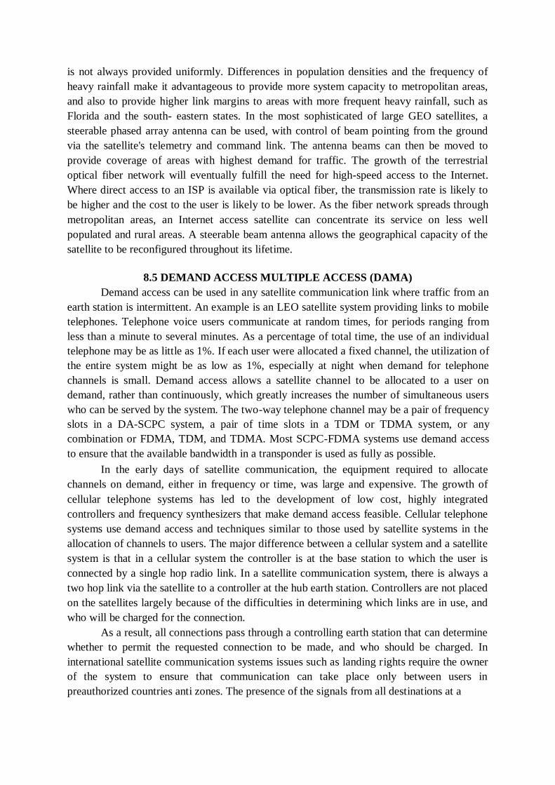
is not always provided uniformly. Differences in population densities and the frequency of
heavy rainfall make it advantageous to provide more system capacity to metropolitan areas,
and also to provide higher link margins to areas with more frequent heavy rainfall, such as
Florida and the south- eastern states. In the most sophisticated of large GEO satellites, a
steerable phased array antenna can be used, with control of beam pointing from the ground
via the satellite's telemetry and command link. The antenna beams can then be moved to
provide coverage of areas with highest demand for traffic. The growth of the terrestrial
optical fiber network will eventually fulfill the need for high-speed access to the Internet.
Where direct access to an ISP is available via optical fiber, the transmission rate is likely to
be higher and the cost to the user is likely to be lower. As the fiber network spreads through
metropolitan areas, an Internet access satellite can concentrate its service on less well
populated and rural areas. A steerable beam antenna allows the geographical capacity of the
satellite to be reconfigured throughout its lifetime.
8.5 DEMAND ACCESS MULTIPLE ACCESS (DAMA)
Demand access can be used in any satellite communication link where traffic from an
earth station is intermittent. An example is an LEO satellite system providing links to mobile
telephones. Telephone voice users communicate at random times, for periods ranging from
less than a minute to several minutes. As a percentage of total time, the use of an individual
telephone may be as little as 1%. If each user were allocated a fixed channel, the utilization of
the entire system might be as low as 1%, especially at night when demand for telephone
channels is small. Demand access allows a satellite channel to be allocated to a user on
demand, rather than continuously, which greatly increases the number of simultaneous users
who can be served by the system. The two-way telephone channel may be a pair of frequency
slots in a DA-SCPC system, a pair of time slots in a TDM or TDMA system, or any
combination or FDMA, TDM, and TDMA. Most SCPC-FDMA systems use demand access
to ensure that the available bandwidth in a transponder is used as fully as possible.
In the early days of satellite communication, the equipment required to allocate
channels on demand, either in frequency or time, was large and expensive. The growth of
cellular telephone systems has led to the development of low cost, highly integrated
controllers and frequency synthesizers that make demand access feasible. Cellular telephone
systems use demand access and techniques similar to those used by satellite systems in the
allocation of channels to users. The major difference between a cellular system and a satellite
system is that in a cellular system the controller is at the base station to which the user is
connected by a single hop radio link. In a satellite communication system, there is always a
two hop link via the satellite to a controller at the hub earth station. Controllers are not placed
on the satellites largely because of the difficulties in determining which links are in use, and
who will be charged for the connection.
As a result, all connections pass through a controlling earth station that can determine
whether to permit the requested connection to be made, and who should be charged. In
international satellite communication systems issues such as landing rights require the owner
of the system to ensure that communication can take place only between users in
preauthorized countries anti zones. The presence of the signals from all destinations at a
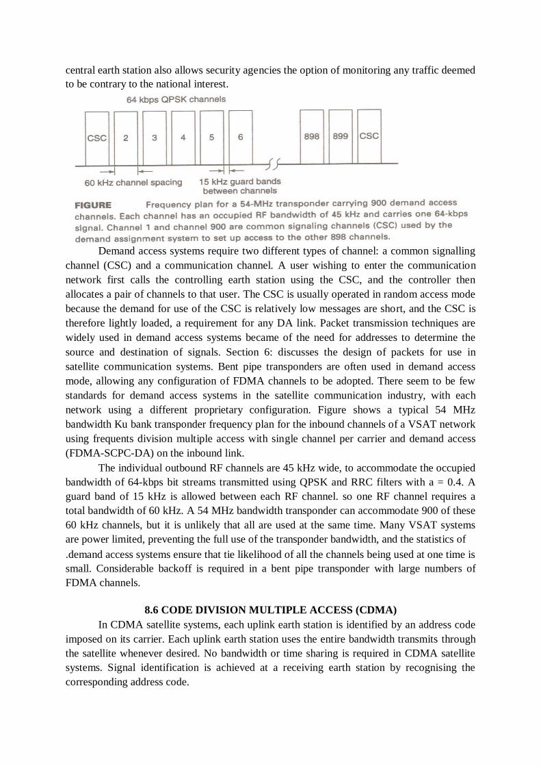
central earth station also allows security agencies the option of monitoring any traffic deemed
to be contrary to the national interest.
Demand access systems require two different types of channel: a common signalling
channel (CSC) and a communication channel. A user wishing to enter the communication
network first calls the controlling earth station using the CSC, and the controller then
allocates a pair of channels to that user. The CSC is usually operated in random access mode
because the demand for use of the CSC is relatively low messages are short, and the CSC is
therefore lightly loaded, a requirement for any DA link. Packet transmission techniques are
widely used in demand access systems became of the need for addresses to determine the
source and destination of signals. Section 6: discusses the design of packets for use in
satellite communication systems. Bent pipe transponders are often used in demand access
mode, allowing any configuration of FDMA channels to be adopted. There seem to be few
standards for demand access systems in the satellite communication industry, with each
network using a different proprietary configuration. Figure shows a typical 54 MHz
bandwidth Ku bank transponder frequency plan for the inbound channels of a VSAT network
using frequents division multiple access with single channel per carrier and demand access
(FDMA-SCPC-DA) on the inbound link.
The individual outbound RF channels are 45 kHz wide, to accommodate the occupied
bandwidth of 64-kbps bit streams transmitted using QPSK and RRC filters with a = 0.4. A
guard band of 15 kHz is allowed between each RF channel. so one RF channel requires a
total bandwidth of 60 kHz. A 54 MHz bandwidth transponder can accommodate 900 of these
60 kHz channels, but it is unlikely that all are used at the same time. Many VSAT systems
are power limited, preventing the full use of the transponder bandwidth, and the statistics of
.demand access systems ensure that tie likelihood of all the channels being used at one time is
small. Considerable backoff is required in a bent pipe transponder with large numbers of
FDMA channels.
8.6 CODE DIVISION MULTIPLE ACCESS (CDMA)
In CDMA satellite systems, each uplink earth station is identified by an address code
imposed on its carrier. Each uplink earth station uses the entire bandwidth transmits through
the satellite whenever desired. No bandwidth or time sharing is required in CDMA satellite
systems. Signal identification is achieved at a receiving earth station by recognising the
corresponding address code.
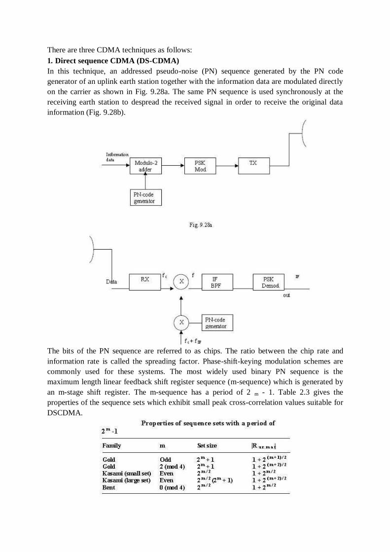
There are three CDMA techniques as follows:
1. Direct sequence CDMA (DS-CDMA)
In this technique, an addressed pseudo-noise (PN) sequence generated by the PN code
generator of an uplink earth station together with the information data are modulated directly
on the carrier as shown in Fig. 9.28a. The same PN sequence is used synchronously at the
receiving earth station to despread the received signal in order to receive the original data
information (Fig. 9.28b).
The bits of the PN sequence are referred to as chips. The ratio between the chip rate and
information rate is called the spreading factor. Phase-shift-keying modulation schemes are
commonly used for these systems. The most widely used binary PN sequence is the
maximum length linear feedback shift register sequence (m-sequence) which is generated by
an m-stage shift register. The m-sequence has a period of 2 m - 1. Table 2.3 gives the
properties of the sequence sets which exhibit small peak cross-correlation values suitable for
DSCDMA.
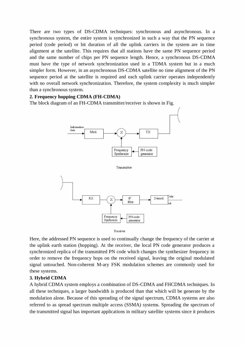
There are two types of DS-CDMA techniques: synchronous and asynchronous. In a
synchronous system, the entire system is synchronized in such a way that the PN sequence
period (code period) or bit duration of all the uplink carriers in the system are in time
alignment at the satellite. This requires that all stations have the same PN sequence period
and the same number of chips per PN sequence length. Hence, a synchronous DS-CDMA
must have the type of network synchronization used in a TDMA system but in a much
simpler form. However, in an asynchronous DS-CDMA satellite no time alignment of the PN
sequence period at the satellite is required and each uplink carrier operates independently
with no overall network synchronization. Therefore, the system complexity is much simpler
than a synchronous system.
2. Frequency hopping CDMA (FH-CDMA)
The block diagram of an FH-CDMA transmitter/receiver is shown in Fig.
Here, the addressed PN sequence is used to continually change the frequency of the carrier at
the uplink earth station (hopping). At the receiver, the local PN code generator produces a
synchronized replica of the transmitted PN code which changes the synthesizer frequency in
order to remove the frequency hops on the received signal, leaving the original modulated
signal untouched. Non-coherent M-ary FSK modulation schemes are commonly used for
these systems.
3. Hybrid CDMA
A hybrid CDMA system employs a combination of DS-CDMA and FHCDMA techniques. In
all these techniques, a larger bandwidth is produced than that which will be generate by the
modulation alone. Because of this spreading of the signal spectrum, CDMA systems are also
referred to as spread spectrum multiple access (SSMA) systems. Spreading the spectrum of
the transmitted signal has important applications in military satellite systems since it produces
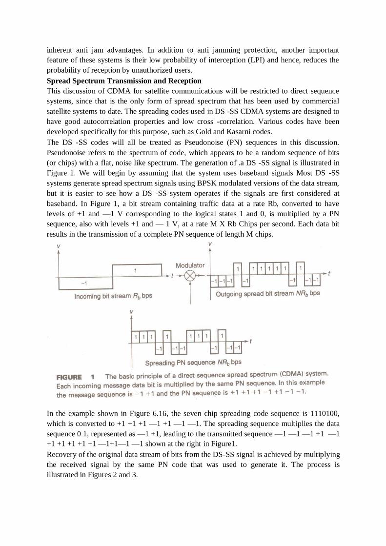
inherent anti jam advantages. In addition to anti jamming protection, another important
feature of these systems is their low probability of interception (LPI) and hence, reduces the
probability of reception by unauthorized users.
Spread Spectrum Transmission and Reception
This discussion of CDMA for satellite communications will be restricted to direct sequence
systems, since that is the only form of spread spectrum that has been used by commercial
satellite systems to date. The spreading codes used in DS -SS CDMA systems are designed to
have good autocorrelation properties and low cross -correlation. Various codes have been
developed specifically for this purpose, such as Gold and Kasarni codes.
The DS -SS codes will all be treated as Pseudonoise (PN) sequences in this discussion.
Pseudonoise refers to the spectrum of code, which appears to be a random sequence of bits
(or chips) with a flat, noise like spectrum. The generation of .a DS -SS signal is illustrated in
Figure 1. We will begin by assuming that the system uses baseband signals Most DS -SS
systems generate spread spectrum signals using BPSK modulated versions of the data stream,
but it is easier to see how a DS -SS system operates if the signals are first considered at
baseband. In Figure 1, a bit stream containing traffic data at a rate Rb, converted to have
levels of +1 and —1 V corresponding to the logical states 1 and 0, is multiplied by a PN
sequence, also with levels +1 and — 1 V, at a rate M X Rb Chips per second. Each data bit
results in the transmission of a complete PN sequence of length M chips.
In the example shown in Figure 6.16, the seven chip spreading code sequence is 1110100,
which is converted to +1 +1 +1 —1 +1 —1 —1. The spreading sequence multiplies the data
sequence 0 1, represented as —1 +1, leading to the transmitted sequence —1 —1 —1 +1 —1
+1 +1 +1 +1 +1 —1+1—1 —1 shown at the right in Figure1.
Recovery of the original data stream of bits from the DS-SS signal is achieved by multiplying
the received signal by the same PN code that was used to generate it. The process is
illustrated in Figures 2 and 3.
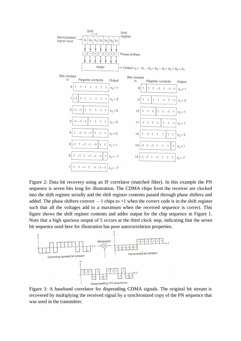
Figure 2: Data bit recovery using an IF correlator (matched filter). In this example the PN
sequence is seven bits long for illustration. The CDMA chips from the receiver are clocked
into the shift register serially and the shift register contents passed through phase shifters and
added. The phase shifters convert —1 chips to +1 when the correct code is in the shift register
such that all the voltages add to a maximum when the received sequence is correct. This
figure shows the shift register contents and adder output for the chip sequence in Figure 1.
Note that a high spurious output of 5 occurs at the third clock step, indicating that the seven
bit sequence used here for illustration has poor autocorrelation properties.
Figure 3: A baseband correlator for dispreading CDMA signals. The original bit stream is
recovered by multiplying the received signal by a synchronized copy of the PN sequence that
was used in the transmitter.

TEXT BOOKS:
1. Satellite communications-Timothy Pratt, Charles Bostian and Jeremy Allnutt,
WSE, Wiley Publications, 2nd
Edition,2003. 2. Satellite communications Engineering-Wilbur L.Pritchard, Robert A Nelson
and Henri G.Suyderhoud, 2nd
Edition, Pearson Publications, 2003. REFERENCES:
1. Satellite communications - Design Principles-M.Richharia, BS Publications, 2nd
Edition,
2003.
Chapter 9: EARTH STATION TECHNOLOGY
9.1 INTRODUCTION
Earth station is a vital element in any satellite communication network. The function of an
earth station is to receive information from or transmit information to, the satellite network in
the most cost-effective and reliable manner while retaining the desired signal quality. The
design of earth station configuration depends upon many factors and its location. But it is
fundamentally governed by its location which are listed below,
• In land
• On a ship at sea
• Onboard aircraft
The factors are
• Type of services
• Frequency bands used
• Function of the transmitter
• Function of the receiver
• Antenna characteristics
EARTH STATION CONFIGURATION
Any earth station consists of four major subsystems
• Transmitter
• Receiver
• Antenna
• Tracking equipment
Two other important subsystems are
• Terrestrial interface equipment
• Power supply.
The earth station depends on the following parameters
• Transmitter power
• Choice of frequency
• Gain of antenna
• Antenna efficiency
• Antenna pointing accuracy
• Noise temperature
• Local conditions such as wind, weather etc,
• Polarization
• Propagation losses
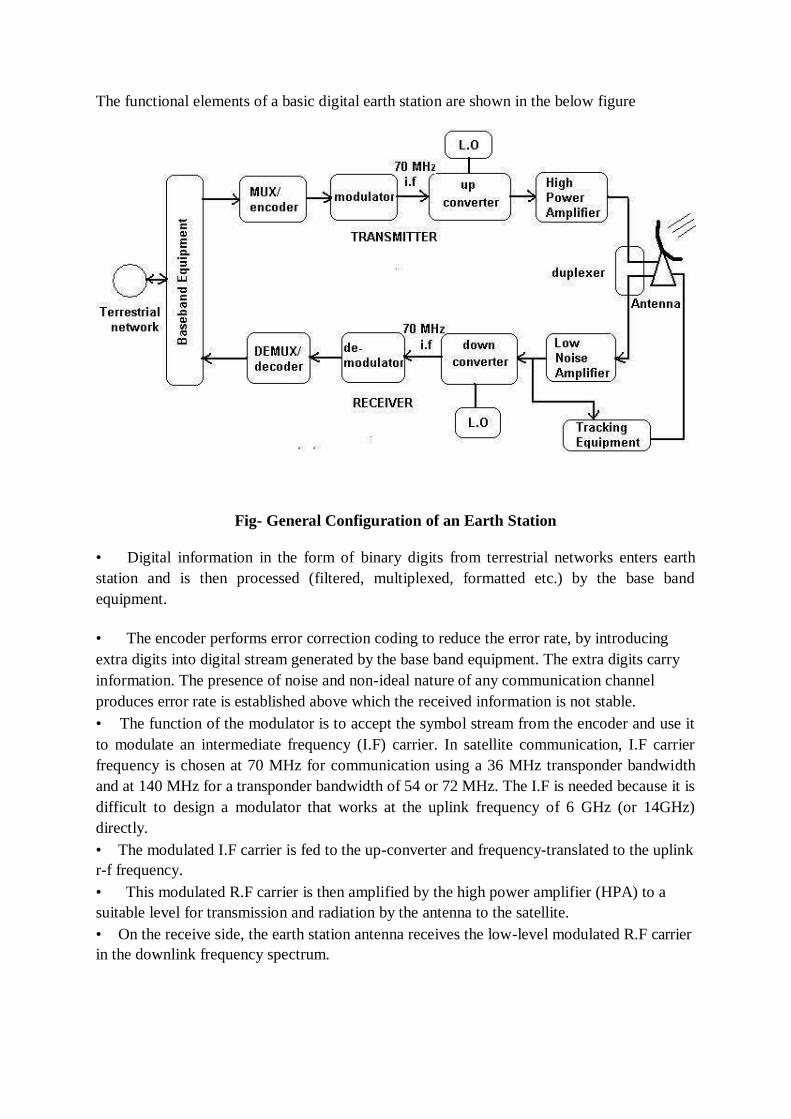
The functional elements of a basic digital earth station are shown in the below figure
Fig- General Configuration of an Earth Station
• Digital information in the form of binary digits from terrestrial networks enters earth
station and is then processed (filtered, multiplexed, formatted etc.) by the base band
equipment.
• The encoder performs error correction coding to reduce the error rate, by introducing
extra digits into digital stream generated by the base band equipment. The extra digits carry
information. The presence of noise and non-ideal nature of any communication channel
produces error rate is established above which the received information is not stable.
• The function of the modulator is to accept the symbol stream from the encoder and use it
to modulate an intermediate frequency (I.F) carrier. In satellite communication, I.F carrier
frequency is chosen at 70 MHz for communication using a 36 MHz transponder bandwidth
and at 140 MHz for a transponder bandwidth of 54 or 72 MHz. The I.F is needed because it is
difficult to design a modulator that works at the uplink frequency of 6 GHz (or 14GHz)
directly.
• The modulated I.F carrier is fed to the up-converter and frequency-translated to the uplink
r-f frequency.
• This modulated R.F carrier is then amplified by the high power amplifier (HPA) to a
suitable level for transmission and radiation by the antenna to the satellite.
• On the receive side, the earth station antenna receives the low-level modulated R.F carrier
in the downlink frequency spectrum.
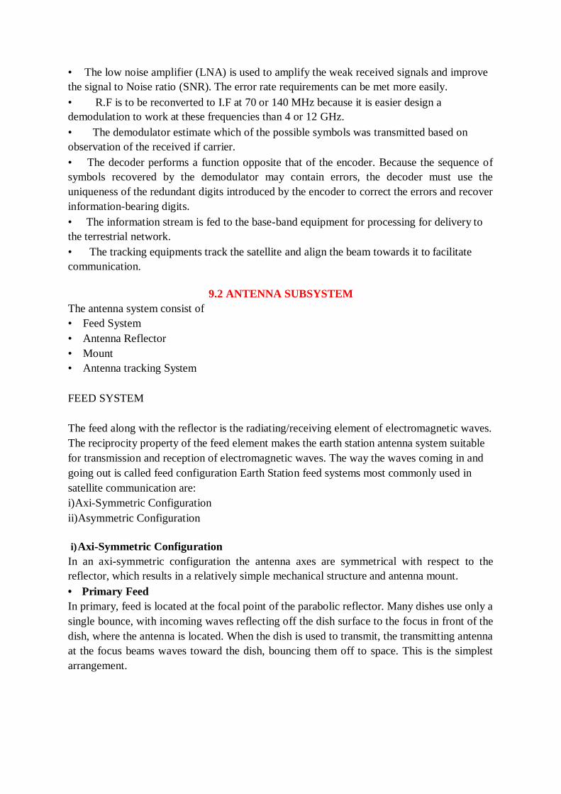
• The low noise amplifier (LNA) is used to amplify the weak received signals and improve
the signal to Noise ratio (SNR). The error rate requirements can be met more easily.
• R.F is to be reconverted to I.F at 70 or 140 MHz because it is easier design a
demodulation to work at these frequencies than 4 or 12 GHz.
• The demodulator estimate which of the possible symbols was transmitted based on
observation of the received if carrier.
• The decoder performs a function opposite that of the encoder. Because the sequence of
symbols recovered by the demodulator may contain errors, the decoder must use the
uniqueness of the redundant digits introduced by the encoder to correct the errors and recover
information-bearing digits.
• The information stream is fed to the base-band equipment for processing for delivery to
the terrestrial network.
• The tracking equipments track the satellite and align the beam towards it to facilitate
communication.
9.2 ANTENNA SUBSYSTEM
The antenna system consist of
• Feed System
• Antenna Reflector
• Mount
• Antenna tracking System
FEED SYSTEM
The feed along with the reflector is the radiating/receiving element of electromagnetic waves.
The reciprocity property of the feed element makes the earth station antenna system suitable
for transmission and reception of electromagnetic waves. The way the waves coming in and
going out is called feed configuration Earth Station feed systems most commonly used in
satellite communication are:
i)Axi-Symmetric Configuration
ii)Asymmetric Configuration
i) Axi-Symmetric Configuration
In an axi-symmetric configuration the antenna axes are symmetrical with respect to the
reflector, which results in a relatively simple mechanical structure and antenna mount.
• Primary Feed
In primary, feed is located at the focal point of the parabolic reflector. Many dishes use only a
single bounce, with incoming waves reflecting off the dish surface to the focus in front of the
dish, where the antenna is located. When the dish is used to transmit, the transmitting antenna
at the focus beams waves toward the dish, bouncing them off to space. This is the simplest
arrangement.
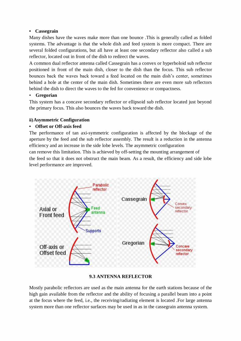
• Cassegrain
Many dishes have the waves make more than one bounce .This is generally called as folded
systems. The advantage is that the whole dish and feed system is more compact. There are
several folded configurations, but all have at least one secondary reflector also called a sub
reflector, located out in front of the dish to redirect the waves.
A common dual reflector antenna called Cassegrain has a convex or hyperboloid sub reflector
positioned in front of the main dish, closer to the dish than the focus. This sub reflector
bounces back the waves back toward a feed located on the main dish‘s center, sometimes
behind a hole at the center of the main dish. Sometimes there are even more sub reflectors
behind the dish to direct the waves to the fed for convenience or compactness.
• Gregorian
This system has a concave secondary reflector or ellipsoid sub reflector located just beyond
the primary focus. This also bounces the waves back toward the dish.
ii) Asymmetric Configuration
• Offset or Off-axis feed
The performance of tan axi-symmetric configuration is affected by the blockage of the
aperture by the feed and the sub reflector assembly. The result is a reduction in the antenna
efficiency and an increase in the side lobe levels. The asymmetric configuration
can remove this limitation. This is achieved by off-setting the mounting arrangement of
the feed so that it does not obstruct the main beam. As a result, the efficiency and side lobe
level performance are improved.
9.3 ANTENNA REFLECTOR
Mostly parabolic reflectors are used as the main antenna for the earth stations because of the
high gain available from the reflector and the ability of focusing a parallel beam into a point
at the focus where the feed, i.e., the receiving/radiating element is located .For large antenna
system more than one reflector surfaces may be used in as in the cassegrain antenna system.
Earth stations are also classified on the basis of services for example:
1.Two way TV ,Telephony and data
2. Two way TV
3.TV receive only and two way telephony and data
4.Two way data
From the classifications it is obvious that the technology of earth station will vary
considerably on the performance and the service requirements of earth station.
For mechanical design of parabolic reflector the following parameters are required to be
considered:
• Size of the reflector
• Focal Length /diameter ratio
• RMS error of main and sub reflector
• Pointing and tracking accuracies
• Speed and acceleration
• Type of mount
• Coverage Requirement
• Wind Speed
The size of the reflector depends on transmit and receive gain requirement and
beamwidth of the antenna. Gain is directly proportional to the antenna diameter whereas the
beamwidth is inversely proportional to the antenna diameter .for high inclination angle of the
satellite, the tracking of the earth station becomes necessary when the beamwidth is too
narrow.
The gain of the antenna is given by
Gain= (η4ΠAeff)/ λ2
Where Aeff is the aperture
λ is wave length
η is efficiency of antenna system
For a parabolic antenna with circular aperture diameter D, the gain of the antenna is :
Gain= (η4Π/ λ2)( ΠD
2
= η (ΠD/ λ)2
The overall efficiency of the antenna is the net product of various factors such as
1. Cross Polarization
2. Spill over
3. Diffraction
4. Blockage
5. Surface accuracy
6. Phase error
7. Illumination
/4)
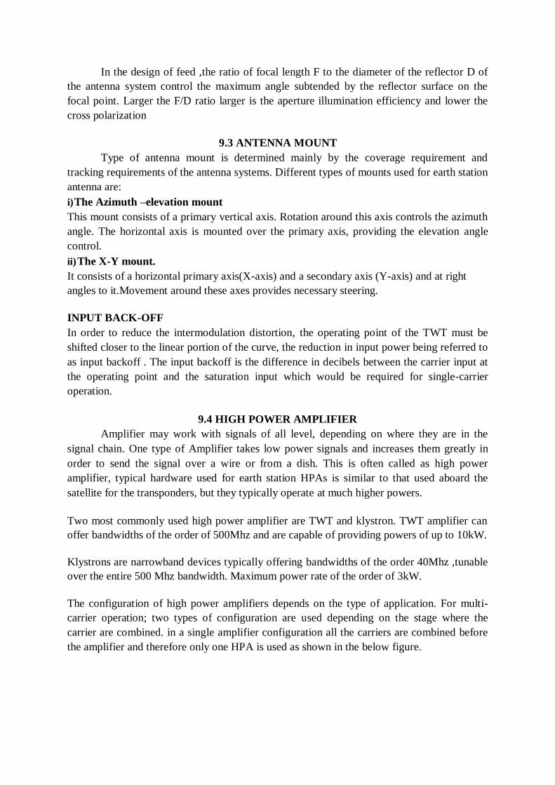
In the design of feed ,the ratio of focal length F to the diameter of the reflector D of
the antenna system control the maximum angle subtended by the reflector surface on the
focal point. Larger the F/D ratio larger is the aperture illumination efficiency and lower the
cross polarization
9.3 ANTENNA MOUNT
Type of antenna mount is determined mainly by the coverage requirement and
tracking requirements of the antenna systems. Different types of mounts used for earth station
antenna are:
i) The Azimuth –elevation mount
This mount consists of a primary vertical axis. Rotation around this axis controls the azimuth
angle. The horizontal axis is mounted over the primary axis, providing the elevation angle
control.
ii) The X-Y mount.
It consists of a horizontal primary axis(X-axis) and a secondary axis (Y-axis) and at right
angles to it.Movement around these axes provides necessary steering.
INPUT BACK-OFF
In order to reduce the intermodulation distortion, the operating point of the TWT must be
shifted closer to the linear portion of the curve, the reduction in input power being referred to
as input backoff . The input backoff is the difference in decibels between the carrier input at
the operating point and the saturation input which would be required for single-carrier
operation.
9.4 HIGH POWER AMPLIFIER
Amplifier may work with signals of all level, depending on where they are in the
signal chain. One type of Amplifier takes low power signals and increases them greatly in
order to send the signal over a wire or from a dish. This is often called as high power
amplifier, typical hardware used for earth station HPAs is similar to that used aboard the
satellite for the transponders, but they typically operate at much higher powers.
Two most commonly used high power amplifier are TWT and klystron. TWT amplifier can
offer bandwidths of the order of 500Mhz and are capable of providing powers of up to 10kW.
Klystrons are narrowband devices typically offering bandwidths of the order 40Mhz ,tunable
over the entire 500 Mhz bandwidth. Maximum power rate of the order of 3kW.
The configuration of high power amplifiers depends on the type of application. For multi-
carrier operation; two types of configuration are used depending on the stage where the
carrier are combined. in a single amplifier configuration all the carriers are combined before
the amplifier and therefore only one HPA is used as shown in the below figure.
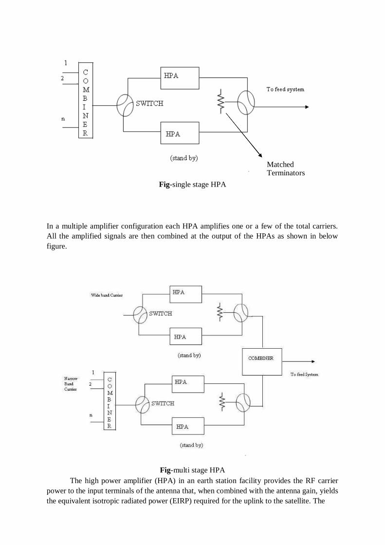
Fig-single stage HPA
In a multiple amplifier configuration each HPA amplifies one or a few of the total carriers.
All the amplified signals are then combined at the output of the HPAs as shown in below
figure.
Fig-multi stage HPA
The high power amplifier (HPA) in an earth station facility provides the RF carrier
power to the input terminals of the antenna that, when combined with the antenna gain, yields
the equivalent isotropic radiated power (EIRP) required for the uplink to the satellite. The
Matched Terminators
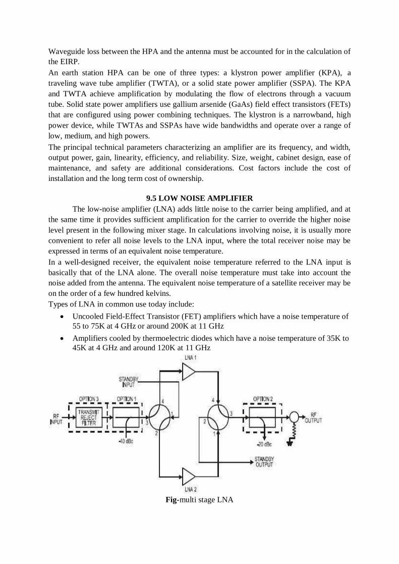
Waveguide loss between the HPA and the antenna must be accounted for in the calculation of
the EIRP.
An earth station HPA can be one of three types: a klystron power amplifier (KPA), a
traveling wave tube amplifier (TWTA), or a solid state power amplifier (SSPA). The KPA
and TWTA achieve amplification by modulating the flow of electrons through a vacuum
tube. Solid state power amplifiers use gallium arsenide (GaAs) field effect transistors (FETs)
that are configured using power combining techniques. The klystron is a narrowband, high
power device, while TWTAs and SSPAs have wide bandwidths and operate over a range of
low, medium, and high powers.
The principal technical parameters characterizing an amplifier are its frequency, and width,
output power, gain, linearity, efficiency, and reliability. Size, weight, cabinet design, ease of
maintenance, and safety are additional considerations. Cost factors include the cost of
installation and the long term cost of ownership.
9.5 LOW NOISE AMPLIFIER
The low-noise amplifier (LNA) adds little noise to the carrier being amplified, and at
the same time it provides sufficient amplification for the carrier to override the higher noise
level present in the following mixer stage. In calculations involving noise, it is usually more
convenient to refer all noise levels to the LNA input, where the total receiver noise may be
expressed in terms of an equivalent noise temperature.
In a well-designed receiver, the equivalent noise temperature referred to the LNA input is
basically that of the LNA alone. The overall noise temperature must take into account the
noise added from the antenna. The equivalent noise temperature of a satellite receiver may be
on the order of a few hundred kelvins.
Types of LNA in common use today include:
Uncooled Field-Effect Transistor (FET) amplifiers which have a noise temperature of
55 to 75K at 4 GHz or around 200K at 11 GHz
Amplifiers cooled by thermoelectric diodes which have a noise temperature of 35K to
45K at 4 GHz and around 120K at 11 GHz
Fig-multi stage LNA
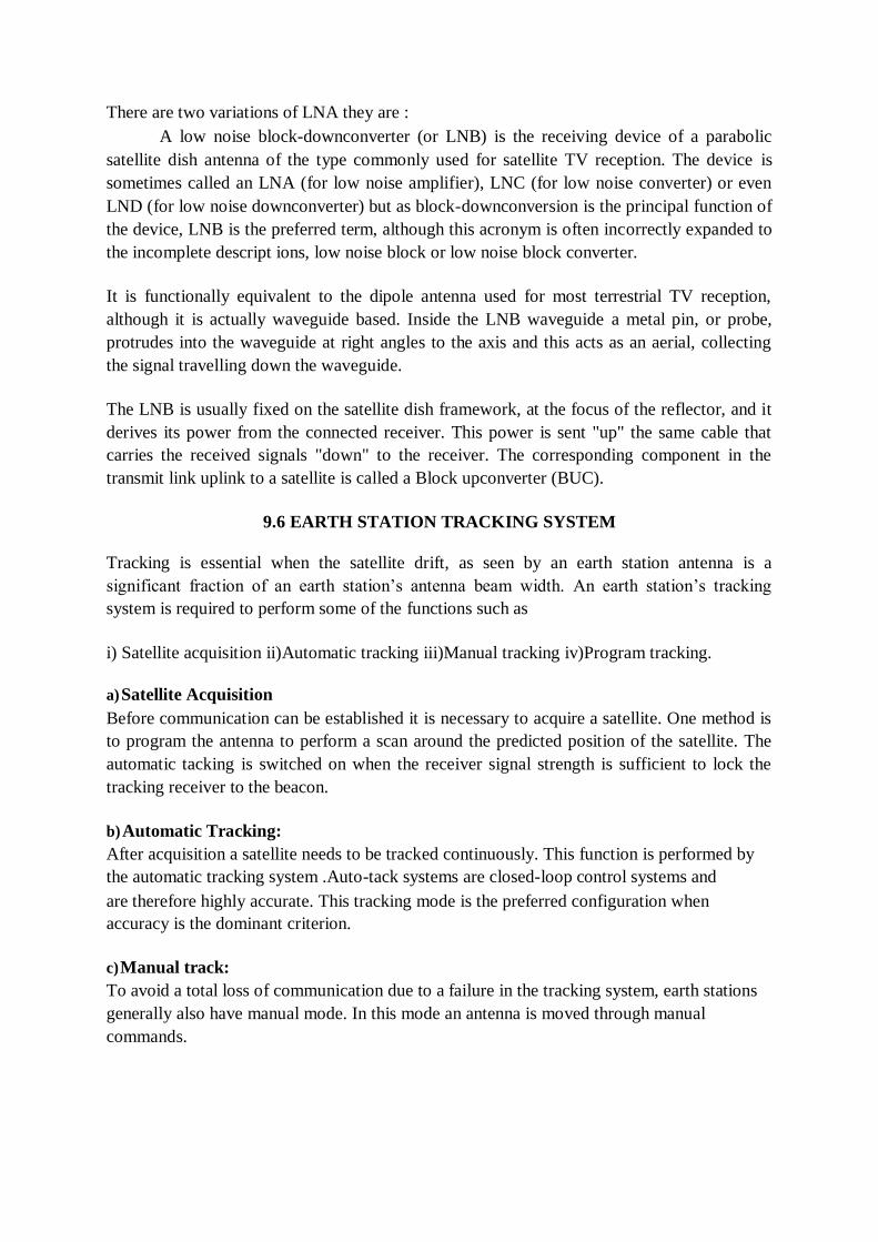
There are two variations of LNA they are :
A low noise block-downconverter (or LNB) is the receiving device of a parabolic
satellite dish antenna of the type commonly used for satellite TV reception. The device is
sometimes called an LNA (for low noise amplifier), LNC (for low noise converter) or even
LND (for low noise downconverter) but as block-downconversion is the principal function of
the device, LNB is the preferred term, although this acronym is often incorrectly expanded to
the incomplete descript ions, low noise block or low noise block converter.
It is functionally equivalent to the dipole antenna used for most terrestrial TV reception,
although it is actually waveguide based. Inside the LNB waveguide a metal pin, or probe,
protrudes into the waveguide at right angles to the axis and this acts as an aerial, collecting
the signal travelling down the waveguide.
The LNB is usually fixed on the satellite dish framework, at the focus of the reflector, and it
derives its power from the connected receiver. This power is sent "up" the same cable that
carries the received signals "down" to the receiver. The corresponding component in the
transmit link uplink to a satellite is called a Block upconverter (BUC).
9.6 EARTH STATION TRACKING SYSTEM
Tracking is essential when the satellite drift, as seen by an earth station antenna is a
significant fraction of an earth station‘s antenna beam width. An earth station‘s tracking
system is required to perform some of the functions such as
i) Satellite acquisition ii)Automatic tracking iii)Manual tracking iv)Program tracking.
a) Satellite Acquisition
Before communication can be established it is necessary to acquire a satellite. One method is
to program the antenna to perform a scan around the predicted position of the satellite. The
automatic tacking is switched on when the receiver signal strength is sufficient to lock the
tracking receiver to the beacon.
b) Automatic Tracking:
After acquisition a satellite needs to be tracked continuously. This function is performed by
the automatic tracking system .Auto-tack systems are closed-loop control systems and
are therefore highly accurate. This tracking mode is the preferred configuration when
accuracy is the dominant criterion.
c) Manual track:
To avoid a total loss of communication due to a failure in the tracking system, earth stations
generally also have manual mode. In this mode an antenna is moved through manual
commands.
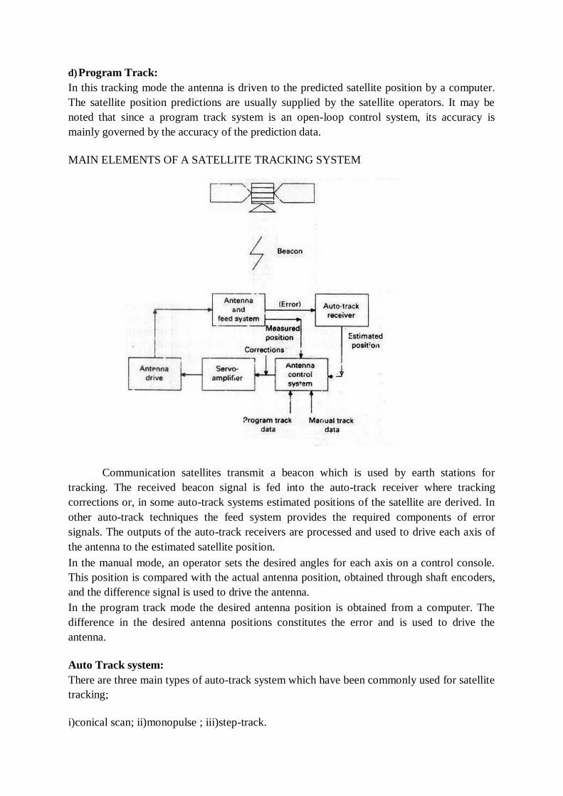
d) Program Track:
In this tracking mode the antenna is driven to the predicted satellite position by a computer.
The satellite position predictions are usually supplied by the satellite operators. It may be
noted that since a program track system is an open-loop control system, its accuracy is
mainly governed by the accuracy of the prediction data.
MAIN ELEMENTS OF A SATELLITE TRACKING SYSTEM
Communication satellites transmit a beacon which is used by earth stations for
tracking. The received beacon signal is fed into the auto-track receiver where tracking
corrections or, in some auto-track systems estimated positions of the satellite are derived. In
other auto-track techniques the feed system provides the required components of error
signals. The outputs of the auto-track receivers are processed and used to drive each axis of
the antenna to the estimated satellite position.
In the manual mode, an operator sets the desired angles for each axis on a control console.
This position is compared with the actual antenna position, obtained through shaft encoders,
and the difference signal is used to drive the antenna.
In the program track mode the desired antenna position is obtained from a computer. The
difference in the desired antenna positions constitutes the error and is used to drive the
antenna.
Auto Track system:
There are three main types of auto-track system which have been commonly used for satellite
tracking;
i)conical scan; ii)monopulse ; iii)step-track.
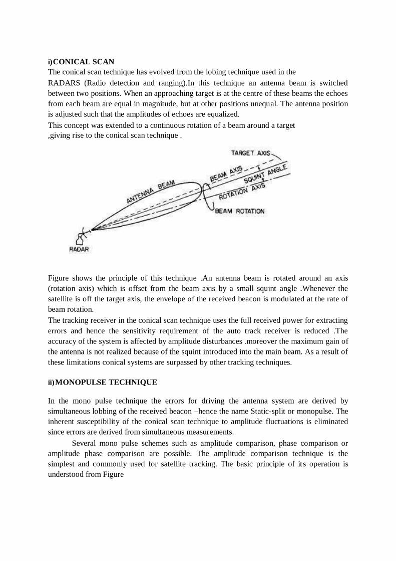
i) CONICAL SCAN
The conical scan technique has evolved from the lobing technique used in the
RADARS (Radio detection and ranging).In this technique an antenna beam is switched
between two positions. When an approaching target is at the centre of these beams the echoes
from each beam are equal in magnitude, but at other positions unequal. The antenna position
is adjusted such that the amplitudes of echoes are equalized.
This concept was extended to a continuous rotation of a beam around a target
,giving rise to the conical scan technique .
Figure shows the principle of this technique .An antenna beam is rotated around an axis
(rotation axis) which is offset from the beam axis by a small squint angle .Whenever the
satellite is off the target axis, the envelope of the received beacon is modulated at the rate of
beam rotation.
The tracking receiver in the conical scan technique uses the full received power for extracting
errors and hence the sensitivity requirement of the auto track receiver is reduced .The
accuracy of the system is affected by amplitude disturbances .moreover the maximum gain of
the antenna is not realized because of the squint introduced into the main beam. As a result of
these limitations conical systems are surpassed by other tracking techniques.
ii) MONOPULSE TECHNIQUE
In the mono pulse technique the errors for driving the antenna system are derived by
simultaneous lobbing of the received beacon –hence the name Static-split or monopulse. The
inherent susceptibility of the conical scan technique to amplitude fluctuations is eliminated
since errors are derived from simultaneous measurements.
Several mono pulse schemes such as amplitude comparison, phase comparison or
amplitude phase comparison are possible. The amplitude comparison technique is the
simplest and commonly used for satellite tracking. The basic principle of its operation is
understood from Figure
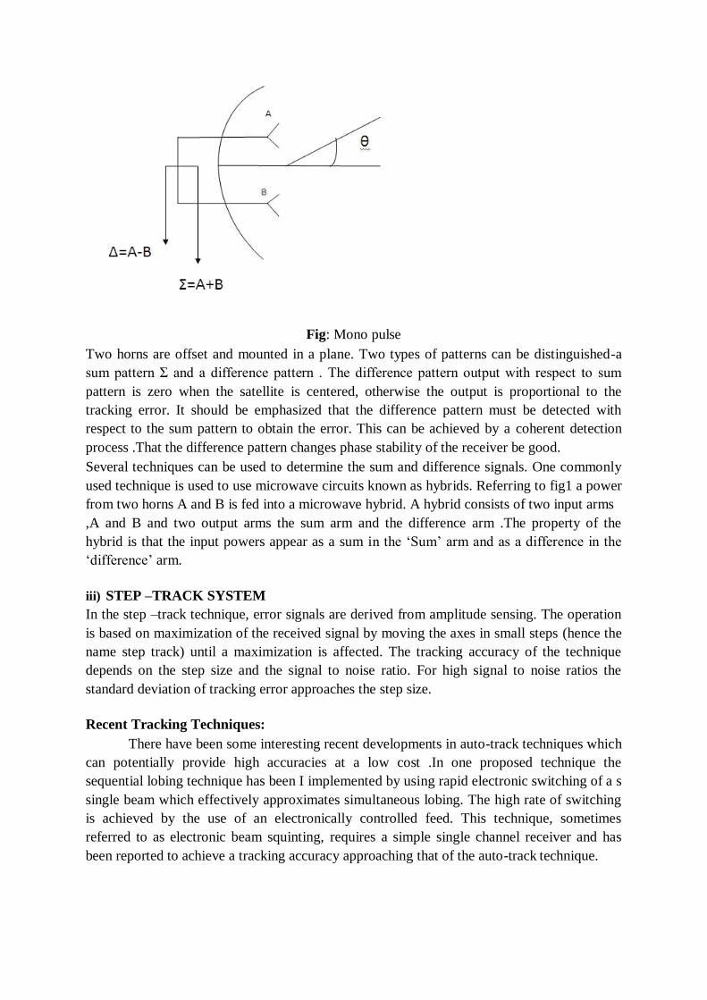
Fig: Mono pulse
Two horns are offset and mounted in a plane. Two types of patterns can be distinguished-a
sum pattern Σ and a difference pattern . The difference pattern output with respect to sum
pattern is zero when the satellite is centered, otherwise the output is proportional to the
tracking error. It should be emphasized that the difference pattern must be detected with
respect to the sum pattern to obtain the error. This can be achieved by a coherent detection
process .That the difference pattern changes phase stability of the receiver be good.
Several techniques can be used to determine the sum and difference signals. One commonly
used technique is used to use microwave circuits known as hybrids. Referring to fig1 a power
from two horns A and B is fed into a microwave hybrid. A hybrid consists of two input arms
,A and B and two output arms the sum arm and the difference arm .The property of the
hybrid is that the input powers appear as a sum in the ‗Sum‘ arm and as a difference in the
‗difference‘ arm.
iii) STEP –TRACK SYSTEM
In the step –track technique, error signals are derived from amplitude sensing. The operation
is based on maximization of the received signal by moving the axes in small steps (hence the
name step track) until a maximization is affected. The tracking accuracy of the technique
depends on the step size and the signal to noise ratio. For high signal to noise ratios the
standard deviation of tracking error approaches the step size.
Recent Tracking Techniques:
There have been some interesting recent developments in auto-track techniques which
can potentially provide high accuracies at a low cost .In one proposed technique the
sequential lobing technique has been I implemented by using rapid electronic switching of a s
single beam which effectively approximates simultaneous lobing. The high rate of switching
is achieved by the use of an electronically controlled feed. This technique, sometimes
referred to as electronic beam squinting, requires a simple single channel receiver and has
been reported to achieve a tracking accuracy approaching that of the auto-track technique.
9.7 TERRESTRIAL INTERFACE:
The terrestrial interface comprises a wide variety of equipment. At one extreme, when the
terminal is a mobile or receive -only station, there may be no terrestrial interface equipment
at all. The operating devices, such as TV receivers, telephones, data sets, and so on, are used
right at the earth station. At the other extreme, we find the interface equipment necessary in a
large commercial satellite system for fixed service. In such cases, hundreds of telephone
channels, together with data and video, are brought to the station by microwave and cable
systems using either frequency- or time -division terrestrial multiplex methods. The signals
must be changed from those formats into formats suitable for satellite transmission. In an
easy case, frequency –division multiplex groups and supergroups, as brought in from
terrestrial transmission facilities, can be transmitted directly or with simple translation in
baseband frequency from the satellite after modulation and up -conversion, but in many cases
it is necessary to reformat extensively for terrestrial circuits. Individual telephone channels,
for instance, May all be transmitted on the same carrier, which is received by many earth
stations in the network. The return channels for particular conversation circuits will be
coming in on various carrier frequencies, depending on their source, and they must be tagged
and put together with the corresponding outgoing circuit to make up a terrestrial circuit. This
can be a complex process. The presence of video and data complicates matters further.
If the satellite transmission is single channel per carrier, it is necessary to bring each
terrestrial carrier down to baseband before remodulation. The interfaces between terrestrial
time –division and satellite frequency –division systems, and vice versa, are complicated and
can be accomplished in a variety of ways. Television video signals must often be separated
from order wire channels, program sound channels, cueing channels, and so on, and then
matched up again at the proper point.
Usually, in the systems engineering and programming planning phase it is only necessary to
be alert to the problems and possibilities, the detailed design can be saved until later in the
program.
9.8 PRIMARY POWER
Primary power systems vary from plain battery- or solar -cell -operated remote transmitters
for data gathering to huge, combined commercial power and diesel generator systems for
large stations. Most transmit and receive earth stations require some kind of "no -break"
power system, that is emergency power to continue the communications during commercial
power outages.
Such power outages are frequent, even in highly organized industrial areas, if for no reason
other than thunderstorms. The no –break transition derives its name from the necessity to
make the change over from one power system to another without any interruption in service.
Almost all systems today use batteries to effect this transition. Some systems have been
devised in which motor generators store enough energy in flywheels to permit a smooth
mechanical transition.
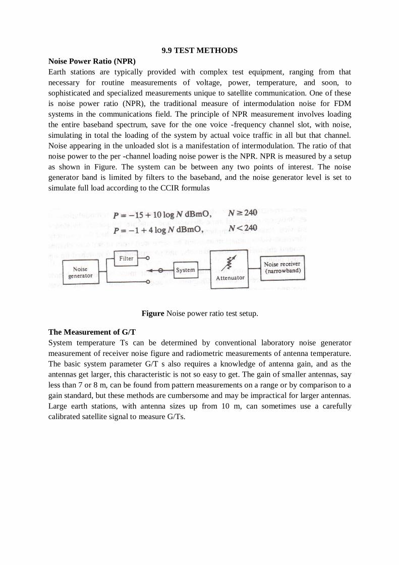
9.9 TEST METHODS
Noise Power Ratio (NPR)
Earth stations are typically provided with complex test equipment, ranging from that
necessary for routine measurements of voltage, power, temperature, and soon, to
sophisticated and specialized measurements unique to satellite communication. One of these
is noise power ratio (NPR), the traditional measure of intermodulation noise for FDM
systems in the communications field. The principle of NPR measurement involves loading
the entire baseband spectrum, save for the one voice -frequency channel slot, with noise,
simulating in total the loading of the system by actual voice traffic in all but that channel.
Noise appearing in the unloaded slot is a manifestation of intermodulation. The ratio of that
noise power to the per -channel loading noise power is the NPR. NPR is measured by a setup
as shown in Figure. The system can be between any two points of interest. The noise
generator band is limited by filters to the baseband, and the noise generator level is set to
simulate full load according to the CCIR formulas
Figure Noise power ratio test setup.
The Measurement of G/T
System temperature Ts can be determined by conventional laboratory noise generator
measurement of receiver noise figure and radiometric measurements of antenna temperature.
The basic system parameter G/T s also requires a knowledge of antenna gain, and as the
antennas get larger, this characteristic is not so easy to get. The gain of smaller antennas, say
less than 7 or 8 m, can be found from pattern measurements on a range or by comparison to a
gain standard, but these methods are cumbersome and may be impractical for larger antennas.
Large earth stations, with antenna sizes up from 10 m, can sometimes use a carefully
calibrated satellite signal to measure G/Ts.
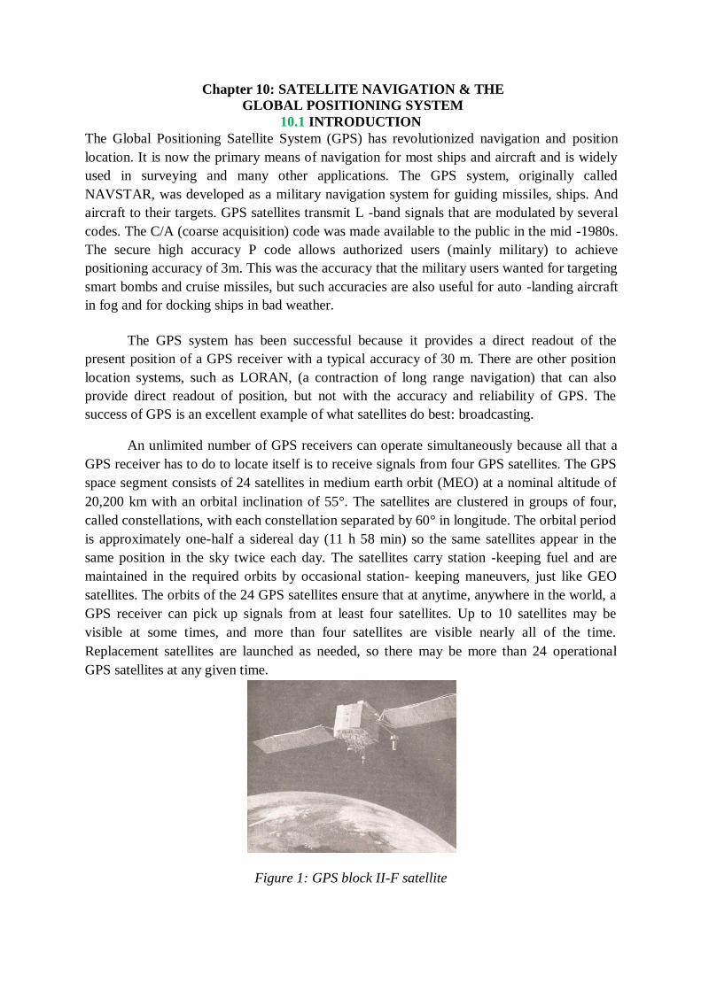
Chapter 10: SATELLITE NAVIGATION & THE
GLOBAL POSITIONING SYSTEM
10.1 INTRODUCTION
The Global Positioning Satellite System (GPS) has revolutionized navigation and position
location. It is now the primary means of navigation for most ships and aircraft and is widely
used in surveying and many other applications. The GPS system, originally called
NAVSTAR, was developed as a military navigation system for guiding missiles, ships. And
aircraft to their targets. GPS satellites transmit L -band signals that are modulated by several
codes. The C/A (coarse acquisition) code was made available to the public in the mid -1980s.
The secure high accuracy P code allows authorized users (mainly military) to achieve
positioning accuracy of 3m. This was the accuracy that the military users wanted for targeting
smart bombs and cruise missiles, but such accuracies are also useful for auto -landing aircraft
in fog and for docking ships in bad weather.
The GPS system has been successful because it provides a direct readout of the
present position of a GPS receiver with a typical accuracy of 30 m. There are other position
location systems, such as LORAN, (a contraction of long range navigation) that can also
provide direct readout of position, but not with the accuracy and reliability of GPS. The
success of GPS is an excellent example of what satellites do best: broadcasting.
An unlimited number of GPS receivers can operate simultaneously because all that a
GPS receiver has to do to locate itself is to receive signals from four GPS satellites. The GPS
space segment consists of 24 satellites in medium earth orbit (MEO) at a nominal altitude of
20,200 km with an orbital inclination of 55°. The satellites are clustered in groups of four,
called constellations, with each constellation separated by 60° in longitude. The orbital period
is approximately one-half a sidereal day (11 h 58 min) so the same satellites appear in the
same position in the sky twice each day. The satellites carry station -keeping fuel and are
maintained in the required orbits by occasional station- keeping maneuvers, just like GEO
satellites. The orbits of the 24 GPS satellites ensure that at anytime, anywhere in the world, a
GPS receiver can pick up signals from at least four satellites. Up to 10 satellites may be
visible at some times, and more than four satellites are visible nearly all of the time.
Replacement satellites are launched as needed, so there may be more than 24 operational
GPS satellites at any given time.
Figure 1: GPS block II-F satellite
Figure.1 shows a GPS satellite. The satellites weigh 1877 kg at launch and have a design
lifetime of 10 years. In 2000, there were 30 GPS satellites in orbit, some of which it were
spares. Because GPS is an integral part of the defence of the United States, spare GPS
satellites are kept in orbit and more spares are ready for immediate launch. The GPS system
is operated by the U.S. Air Force from the GPS master control station (MCS) at Falcon Air
Force Base in Colorado Springs, Colorado. The MCS and a series of subsidiary control
stations around the globe continuously monitor all GPS satellites as they come into view and
determine the orbit of each satellite. The MCS and other stations calculate ephemeris data for
each satellite, atomic clock error, and numerous other parameters needed for the navigation
message.
The data are then transmitted to the satellite using a secure S -band link and used to update
onboard data. There are five GPS monitor stations located in Hawaii, Colorado Springs,
Ascension Island in the Atlantic Ocean, Diego Garcia in the Indian Ocean and Kwajalein in
the Pacific Ocean'. The monitor stations have precise cesium time standards and make
continuous measurements of range to all visible satellites. These measurements are
performed every 1.5 s, and used to provide updates for the navigation messages.
The position of a GPS receiver is found by trilateration, which is one of the simplest and
most accurate methods of locating an unknown position. In trilateration, the distance of the
unknown point from three known points is measured. The intersection of the arcs
corresponding to three distances defines the unknown point relative to the known points,
since three measurements can be used to solve three equations to give the latitude, longitude,
and elevation of the receiver. The distance between a transmitter and a receiver can be found
by measuring the time it takes for a pulse of RF energy to travel between the two. The
distance is calculated using the velocity of electromagnetic waves in free space, which is
assumed to be equal the velocity of light, c, with c = 299,792,458 m/s. Time can be measured
electronically more accurately than any other parameter by the use of atomic clocks, and this
is how the GPS position location system can achieve a measurement accuracy of 1 m in a
distance of 20,000 km. To achieve a position location accuracy of 1 m, timing measurements
must have an accuracy better than 3 ns. This is possible with modern digital circuitry and a
great deal of averaging.
Each satellite carries several high accuracy atomic clocks and radiates a sequence of
bits that starts at a precisely known time. A GPS receiver contains a clock that is
synchronized in turn to the clock on each satellite that it is receiving. The receiver measures
the time delay of the arrival of the bit sequence, which is proportional to the distance between
the satellite and the GPS receiver. When the distance of a GPS receiver from three satellites
has been measured, the remaining piece of information that is required is the position of each
satellite. This is calculated in the GPS receiver using the ephemeris for the satellite orbits that
are broadcast by each satellite in its navigation message. Since the time at which the
transmitted bit sequence started is known at the receiver, the position of the satellite at that
time can be calculated from its orbital data. Making the calculation for four satellites provides
the receiver with sufficient information to determine its position with very good accuracy.
Four satellites, rather than three, are needed because the clock in the receiver is not inherently
accurate enough. The fourth distance measurement provides information from which clock
errors in the receiver can be corrected and the receiver clock synchronized to GPS time with
an accuracy better than 100 ns.
GPS satellites transmit two signals at different frequencies, known as L1 and L2. The
L2 signal is modulated with a 10.23 Mbps pseudorandom (PN) bit sequence called the P code
that is used by military positioning systems. The P code is transmitted in an encrypted form
known as the Y code, which restricts the use of the P code to authorized users.
The L1 frequency carrier is modulated by a 1.023 Mbps PN sequence called the C/A
code that is available for public use, and also carries the P code as a quadrature modulation.
The higher bit rate of the P code provides better measurement accuracy than the 1.023 Mbps
C/A code. C/A stands for coarse acquisition and P stands for precise.
GPS systems using the secure Y code require the C/A code as an intermediate step in making
distance measurements with high accuracy. The accuracy of C/A code receivers was
deliberately degraded some of the time by a process called selective availability(SA). SA
causes variations in the C/A code satellite transmissions that result in less accurate calculation
of position. SA was discontinued in May 2000, but can be reinstituted if the President of the
United States declares a National Emergency. The GPS system provides two categories of
service. The precise positioning service (PPS) receivers track both P code and C/A code on
L1 and L2 frequencies. The PPS is used mainly by military users, since the P code is
encrypted into the Y code before transmission and requires decryption equipment in the
receiver. Standard positioning service (S PS) receivers track the C/A code on L1. This is the
service that is used by the general public. The P(Y) and C/A codes transmitted by each
satellite create direct sequence spread spectrum signals which occupy the same frequency
bands. Both the C/A codes and the P codes are publicly available, but the P code cannot be
recovered in a GPS receiver without a knowledge of the Y code decryption algorithm. In this
discussion we will concentrate on the C/A code and its use in position location.
The former USSR built and operated a global navigation system that is very similar to GPS,
known in the West as Glonass for global navigation satellite system. Almost everything about
Glonass is similar to GPS except the multiple access technique. Glonass uses FDMA, with a
different transmit frequency at each satellite. The equivalents of the P code and C/A code can
be transmitted by Glonass satellites in RF bandwidths of 20 kHz and 2 kHz, so 100 satellites
can be accommodated in a bandwidth of 2 MHz. An FDMA receiver with 100 channels is
simpler than a CDMA receiver. A frequency synthesizer that can be tuned to the unique
frequency of each satellite is required, rather than the digital correlators that recover the GPS
signals in a CDMA receiver.
The European Union is considering building a similar satellite navigation system called
Galileo, scheduled for operation by 2008, to provide precise navigation signals without
dependence on the United States.
10.2 RADIO AND SATELLITE NAVIGATION
Prior to the development of radio, navigation was by compass and landmarks on land, and by
the sun and stars at sea. Neither technique provides high accuracy, and shipwrecks mused by
inaccurate navigation and foggy weather were a common occurrence. On land, people often
got lost in wilderness areas (and still do). Pilots of light aircraft, relying solely on a map and
landmarks, would get lost and run out of fuel before they found some- where to land. With a
GPS receiver and a map, it is impossible to get lost. GPS receivers we very popular with
airplane pilots, owners of sea -going boats, and wilderness hikers. The development of
aircraft that could fly above the clouds, and particularly the building of large numbers of
bomber aircraft in the 1930s, made radio navigation essential Military thinking after WWI,
and during WWII, placed high reliance on the ability bomber aircraft to win a war by
destroying the weapon manufacturing capability of the my. During WWII, the allies sent
1000 bomber aircraft at a time to targets in Germany, causing immense destruction to many
cities. The philosophy of mass destruction continued after WWII with the development of
nuclear bombs, intercontinental ballistic missiles (ICBMs), and cruise missiles. However,
bomber aircraft, ICBMs, and cruise missiles must their targets, so accurate navigation is an
essential part of each of these weapon sys- This demand for accurate targeting of airborne
weapons led to the development of However, the majority of GPS users are now civilian, and
the worldwide market for equipment is projected to be worth $25 B by 2005.
Commercial aircraft fly on federal airways using VOR (VHF omni range) beacons. airways
are 8 miles wide to allow for the angular accuracy of VOR measurements, which is better
than 4°. GPS will eventually replace VOR navigation, allowing aircraft to directly from point
of origin to destination, but the system of VCR beacons in the ted States is likely to remain
for many years as a backup to GPS.
GPS can provide a single navigation system with better accuracy and reliability than earlier
radio navigation aids. It can provide navigation of aircraft directly between air-instead of
indirectly via airways, while providing absolute position readout of latitude and longitude.
Differential GPS can be used instead of ILS to provide the required straight line in the sky for
an instrument approach to a runway, and can be linked to an pilot to provide automatic
landing of aircraft in zero visibility conditions. Ships can safely navigate and dock in
treacherous waters in bad weather by using differential GPS. Eventually, GPS will replace all
other means of navigation, although some may be retained as backup systems in case of
failure of the GPS receiver(s) or jamming of the signals.
GPS was preceded by an earlier satellite navigation system called Transit, built for U.S. Navy
for ship navigation, which achieved much lower accuracy and became obsolete when GPS
was introduced. Transit satellites were in low earth orbits and the system used the Doppler
shift observed at the receiver when a beacon signal was transmitted by the satellite. Because
of the high velocity of LEO satellites—about 7.5 km/s— their signals are significantly shifted
up in frequency when the satellite appears over the horizon with a component of velocity
toward the receiver. The Doppler shift falls to zero as the satellite passes the observer, and
then becomes negative as the satellite flies away.
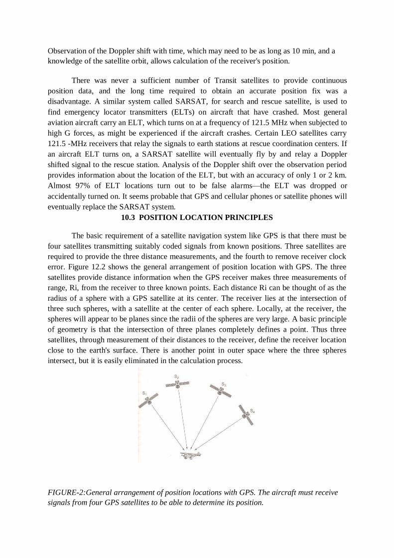
Observation of the Doppler shift with time, which may need to be as long as 10 min, and a
knowledge of the satellite orbit, allows calculation of the receiver's position.
There was never a sufficient number of Transit satellites to provide continuous
position data, and the long time required to obtain an accurate position fix was a
disadvantage. A similar system called SARSAT, for search and rescue satellite, is used to
find emergency locator transmitters (ELTs) on aircraft that have crashed. Most general
aviation aircraft carry an ELT, which turns on at a frequency of 121.5 MHz when subjected to
high G forces, as might be experienced if the aircraft crashes. Certain LEO satellites carry
121.5 -MHz receivers that relay the signals to earth stations at rescue coordination centers. If
an aircraft ELT turns on, a SARSAT satellite will eventually fly by and relay a Doppler
shifted signal to the rescue station. Analysis of the Doppler shift over the observation period
provides information about the location of the ELT, but with an accuracy of only 1 or 2 km.
Almost 97% of ELT locations turn out to be false alarms—the ELT was dropped or
accidentally turned on. It seems probable that GPS and cellular phones or satellite phones will
eventually replace the SARSAT system.
10.3 POSITION LOCATION PRINCIPLES
The basic requirement of a satellite navigation system like GPS is that there must be
four satellites transmitting suitably coded signals from known positions. Three satellites are
required to provide the three distance measurements, and the fourth to remove receiver clock
error. Figure 12.2 shows the general arrangement of position location with GPS. The three
satellites provide distance information when the GPS receiver makes three measurements of
range, Ri, from the receiver to three known points. Each distance Ri can be thought of as the
radius of a sphere with a GPS satellite at its center. The receiver lies at the intersection of
three such spheres, with a satellite at the center of each sphere. Locally, at the receiver, the
spheres will appear to be planes since the radii of the spheres are very large. A basic principle
of geometry is that the intersection of three planes completely defines a point. Thus three
satellites, through measurement of their distances to the receiver, define the receiver location
close to the earth's surface. There is another point in outer space where the three spheres
intersect, but it is easily eliminated in the calculation process.
FIGURE-2:General arrangement of position locations with GPS. The aircraft must receive
signals from four GPS satellites to be able to determine its position.
Although the principles by which GPS locates a receiver are very simple, requiring
only the accurate Measurement of three ranges to three satellites implementing the
measurement with the required accuracy is quite complex. We will look first at the way in
which range is measured in a GPS receiver and then consider how to make the
measurements. Range is calculated from the time delay incurred by the satellite signal in
traveling from the satellite to the GPS receiver, using the known velocity of EM waves in
free space. To measure the time delay, we must know the precise instant at which the signal
was transmitted, and we must have a clock in the receiver that is synchronized to the clock on
the satellite.
GPS satellites each carry four atomic clocks which are calibrated against time standards in
the GPS control stations around the world. The result is GPS time, a time standard that is
available in every GPS satellite. The accuracy of an atomic clock is typically 1 part in 1011.
However, it is too expensive to include an atomic clock in most GPS receivers, so a standard
crystal oscillator with an accuracy of 1 in 105 or 1 in 106 is used instead. The receiver clock
is allowed to have an offset relative to the GPS satellite clocks, so when a time delay
measurement is made, the measurement will have an error caused by the clock offset.
For example, suppose the receiver clock has an offset of 10ms relative to GPS time. All
distance measurements will then have an error of 3000 km. Clearly, we must have a way to
remove the time error from the receiver clock before we can make accurate position
measurements. C/A code receivers can synchronize their internal clocks to GPS time within
170 ns, corresponding to a distance measurement uncertainty of 50m.Repeated measurements
and integration improve the position location error to well below 50 m.
It is surprisingly easy to remove the clock error, and this removal is one of the
strengths of GPS. All that is needed is a time measurement from a fourth satellite. We need
three time measurements to define the location of the receiver in the three unknown
coordinates x, y, and z. When we add a fourth time measurement we can solve the basic
position location equations for a fourth unknown, the receiver clock offset error τ. Thus the
four unknowns in the calculation of the location of the receiver are x, y, z, and τ.
Position Location in GPS
First, we will define the coordinates of the GPS receiver and the GPS satellites in a
rectangular coordinate system with its origin at the center of the earth. This is called the earth
centered earth fixed (ECEF) coordinate system, and is part of the WGS-84 description of the
earth. WGS-84 is an internationally agreed description of the earth's shape and parameters,
derived from observations in many countries 4. GPS receivers use the WGS-84 parameters to
calculate the orbits of the GPS satellites with the accuracy required for precise measurement
of the range to the satellites. The Z-axis of the coordinate system is directed through the
earth's North Pole and the X-and Y-axes are in the equatorial plane. The X-axis passes
through the Greenwich meridian—the line of zero longitude on the earth's surface, and the Y-
axis passes through the 90° east meridian. The ECEF coordinate system rotates with the
earth. The receiver coordinates are (Ux, Uy, Uz),and the four satellites have coordinates
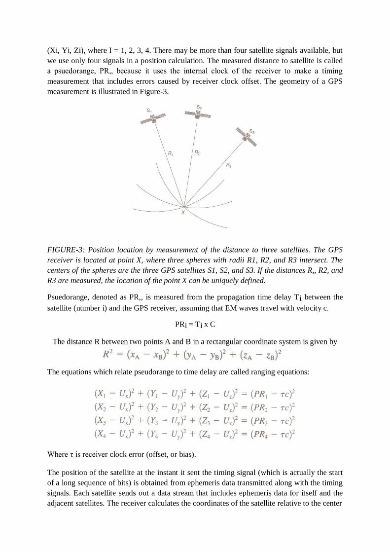
(Xi, Yi, Zi), where I = 1, 2, 3, 4. There may be more than four satellite signals available, but
we use only four signals in a position calculation. The measured distance to satellite is called
a psuedorange, PR„ because it uses the internal clock of the receiver to make a timing
measurement that includes errors caused by receiver clock offset. The geometry of a GPS
measurement is illustrated in Figure-3.
FIGURE-3: Position location by measurement of the distance to three satellites. The GPS
receiver is located at point X, where three spheres with radii R1, R2, and R3 intersect. The
centers of the spheres are the three GPS satellites S1, S2, and S3. If the distances R,, R2, and
R3 are measured, the location of the point X can be uniquely defined.
Psuedorange, denoted as PR,, is measured from the propagation time delay Ti between the
satellite (number i) and the GPS receiver, assuming that EM waves travel with velocity c.
PRi = Ti x C
The distance R between two points A and B in a rectangular coordinate system is given by
The equations which relate pseudorange to time delay are called ranging equations:
Where τ is receiver clock error (offset, or bias).
The position of the satellite at the instant it sent the timing signal (which is actually the start
of a long sequence of bits) is obtained from ephemeris data transmitted along with the timing
signals. Each satellite sends out a data stream that includes ephemeris data for itself and the
adjacent satellites. The receiver calculates the coordinates of the satellite relative to the center
of the earth, (XiYi,Zi), and then solves the four ranging equations for the four unknowns
using standard numerical techniques for the solution of nonlinear simultaneous equations.
(The equations are nonlinear because of the squared terms.)
The four unknowns are the location of the GPS receiver, (Ux,Uy,Uz), relative to the center of
the earth and the clock offset τ –called clock bias in GPS terminology. The receiver position
is then referenced to the surface of the earth, and can be displayed in latitude, longitude, and
elevation. Typical accuracy for a low-cost GPS receiver using the GPS C/A code is 30 m
defined as a 2DRMS error. The term DRMS means the distance root mean square error of the
measured position relative to the true position of the receiver. If the measurement errors are
Gaussian distributed, as is often the case. 68% of the measured position results will be within
a distance of 1DRMS from the true location and 95% of the results will be within 2DRMS of
the true location. Accuracy in GPS measurements is usually defined in terms of 2DRMS, in
the horizontal or vertical plane.
In practice, the error surface that encloses 68 or 95% of all measurements is not a circle but
an ellipse, and the error in any dimension is affected by several dilution of precision (DOP)
factors. DOP is discussed later in this chapter. The U.S. Department of Defense has the
ability to degrade the position measurement accuracy of C/A code receivers by applying
selective availability (SA). SA exists to allow the accuracy of C/A code receivers to be
degraded in the event of a national emergency (i.e., enemy action) affecting the United States
and was applied to the C/A signals most of the time until May2000. SA was switched off on
May 1, 2000, and will not be used again unless the security of the United States is threatened.
With SA off, the' accuracy of GPS position measurements with the C/A code increased
dramatically, particularly in the vertical dimension. Variation in elevation readout of a typical
C/A code receiver with SA on could be as large as 200 m. With SA off, the variation may be
as small as 10 m.
Selective availability and atmospheric propagation effects (tropospheric and ionospheric) all
cause errors in the timing measurements made by a GPS receiver, leading to position location
errors. The atmosphere and the ionosphere introduce timing errors because the propagation
velocity of the GPS signals deviates from the assumed free space value. The errors can be
largely removed if a number of GPS reference stations are built at precisely known locations.
The stations observe the GPS signals and compute the current error in position as calculated
from GPS data. This information can then be broadcast to all GPS users as a set of
corrections to be applied to GPS measurements. The system is called a wide area
augmentation system(WAAS).
A network of 24 WAAS stations built in North America for the U.S. Federal Aviation
Administration (FAA) provides aircraft with improved position measurement accuracy.
Using WAAS, accuracies of a few meters can be obtained with C/A code receivers. In the
event of a national emergency, WAAS would be switched off to prevent enemies using GPS
for accurate targeting of weapons. WAAS also includes an integrity monitoring system to
ensure that the GPS signals used by aircraft do not contain errors which could cause false
readings. WAAS is required to send a warning of possible errors within 5.6 s if a problem is
detected with any GPS satellite signal.
Similarly, a single reference station at a known location—for example, an airport— can
determine the local measurement error in GPS and broadcast this information to GPS users so
that greater accuracy can be obtained with a C/A code receiver. This is one (simple) form of
differential GPS (DGPS). More complex forms of differential GPS use a reference station
which transmits the signals received from each GPS satellite so that phase comparisons can
be made by the receiver. With lengthy integration times and a sophisticated phase comparison
receiver, differential GPS accuracies of 1 cm can be obtained. With DGPS, the receiver
computes its position relative to the reference station rather than in latitude and longitude.
Differential GPS is used when a vehicle needs to be positioned accurately with respect to a
fixed point, such as an aircraft with respect to a runway or a ship with respect to a berth.
GPS Time
The clock bias value T which is found as part of the position location calculation process can
be added to the GPS receiver clock time to yield a time measurement that is synchronized to
the GPS time standard. The crystal oscillator used in the GPS receiver is highly stable over a
period of a few seconds, but will have a frequency which changes with temperature and with
time. Temperature changes cause the quartz crystal that is the frequency determining element
of a crystal oscillator to expand or contract, and this changes the oscillator frequency.
Crystals also age, which causes the frequency to change with time. The changes are very
small, but sufficient to cause errors in the clock time at the receiver when the clock is not
synchronized to a satellite. Calculating the clock bias by solving ranging equations allows the
receiver clock time to be updated every second or two so that the GPS receiver time readout
is identical to GPS time.
Every GPS receiver is automatically synchronized to every other GPS receiver any- where in
the world through GPS time. This makes every GPS receiver a super clock, which knows
time more accurately than any other time standard. Prior to the widespread use of GPS
receivers, standard time transmissions were broadcast by the U.S. National Institute of
Science and Technology (NIST, formerly the Bureau of Standards). The broadcasts were
made in the HF (shortwave) band, and could be received throughout the United States.
However, the HF signals propagate over long distance by reflection from the ionosphere,
which introduces an uncertain delay into the time of arrival of the signal. The time standard
provided by GPS is typically accurate to better than 170 ns, and has been used to synchronize
electric power generators across the United States, for scientific applications that require
synchronized clocks in different locations, and as a long-term frequency standard.
The time standard on board each GPS satellite consists of two cesium clocks plus two
rubidium clocks (atomic clocks). An atomic clock uses the fundamental resonance of the
cesium or rubidium molecule as a frequency reference to lock a crystal oscillator. In the GPS
satellites, the master oscillator is at 10.23 MHz; all code rates, the Li, and the L2 RF
frequencies are multiples or submultiples of 10.23 MHz. The atomic clocks are updated by
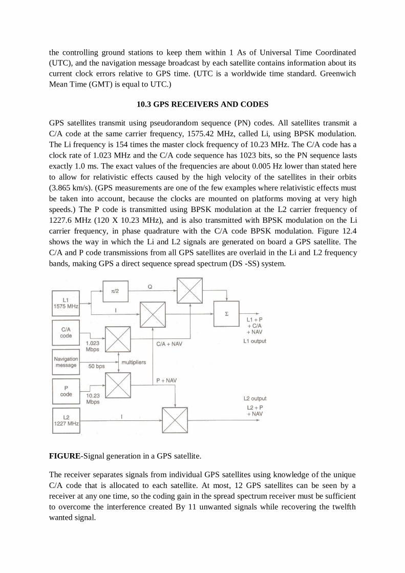
the controlling ground stations to keep them within 1 As of Universal Time Coordinated
(UTC), and the navigation message broadcast by each satellite contains information about its
current clock errors relative to GPS time. (UTC is a worldwide time standard. Greenwich
Mean Time (GMT) is equal to UTC.)
10.3 GPS RECEIVERS AND CODES
GPS satellites transmit using pseudorandom sequence (PN) codes. All satellites transmit a
C/A code at the same carrier frequency, 1575.42 MHz, called Li, using BPSK modulation.
The Li frequency is 154 times the master clock frequency of 10.23 MHz. The C/A code has a
clock rate of 1.023 MHz and the C/A code sequence has 1023 bits, so the PN sequence lasts
exactly 1.0 ms. The exact values of the frequencies are about 0.005 Hz lower than stated here
to allow for relativistic effects caused by the high velocity of the satellites in their orbits
(3.865 km/s). (GPS measurements are one of the few examples where relativistic effects must
be taken into account, because the clocks are mounted on platforms moving at very high
speeds.) The P code is transmitted using BPSK modulation at the L2 carrier frequency of
1227.6 MHz (120 X 10.23 MHz), and is also transmitted with BPSK modulation on the Li
carrier frequency, in phase quadrature with the C/A code BPSK modulation. Figure 12.4
shows the way in which the Li and L2 signals are generated on board a GPS satellite. The
C/A and P code transmissions from all GPS satellites are overlaid in the Li and L2 frequency
bands, making GPS a direct sequence spread spectrum (DS -SS) system.
FIGURE-Signal generation in a GPS satellite.
The receiver separates signals from individual GPS satellites using knowledge of the unique
C/A code that is allocated to each satellite. At most, 12 GPS satellites can be seen by a
receiver at any one time, so the coding gain in the spread spectrum receiver must be sufficient
to overcome the interference created By 11 unwanted signals while recovering the twelfth
wanted signal.
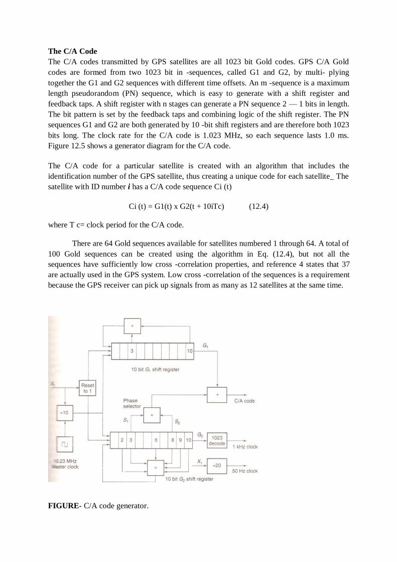
The C/A Code
The C/A codes transmitted by GPS satellites are all 1023 bit Gold codes. GPS C/A Gold
codes are formed from two 1023 bit in -sequences, called G1 and G2, by multi- plying
together the G1 and G2 sequences with different time offsets. An m -sequence is a maximum
length pseudorandom (PN) sequence, which is easy to generate with a shift register and
feedback taps. A shift register with n stages can generate a PN sequence 2 — 1 bits in length.
The bit pattern is set by the feedback taps and combining logic of the shift register. The PN
sequences G1 and G2 are both generated by 10 -bit shift registers and are therefore both 1023
bits long. The clock rate for the C/A code is 1.023 MHz, so each sequence lasts 1.0 ms.
Figure 12.5 shows a generator diagram for the C/A code.
The C/A code for a particular satellite is created with an algorithm that includes the
identification number of the GPS satellite, thus creating a unique code for each satellite_ The
satellite with ID number i has a C/A code sequence Ci (t)
Ci (t) = G1(t) x G2(t + 10iTc) (12.4)
where T c= clock period for the C/A code.
There are 64 Gold sequences available for satellites numbered 1 through 64. A total of
100 Gold sequences can be created using the algorithm in Eq. (12.4), but not all the
sequences have sufficiently low cross -correlation properties, and reference 4 states that 37
are actually used in the GPS system. Low cross -correlation of the sequences is a requirement
because the GPS receiver can pick up signals from as many as 12 satellites at the same time.
FIGURE- C/A code generator.

A correlator in the receiver looks for one of the sequences and must reject all other sequences
that are present. Two C/A code sequences with zero cross -correlation would achieve a
rejection ratio of 1023, but the 64 available C/A code sequences will not all have zero cross -
correlation. The selected group of 37 are the sequences with the lowest levels of cross -
correlation among the available set of 100 Gold code sequences. They also have low
autocorrelation time sidelobes, another requirement of direct sequence spread spectrum
systems.
The C/A code sequence length of 1.000 ms gives range ambiguity of 300 km, since 8
the code travels at a velocity of approximately 3 x 10 m/s and therefore has a length in space 5
of 3x10 m. The entire C/A code sequence repeats in space every 300 km, leading to
ambiguity of position only if the GPS receiver is in outer space, The ambiguity easily
resolved if the receiver knows roughly where it is; just knowing that the receiver is located
close to the earth's surface is usually sufficient. The user can enter the approximate location
of the GPS receiver when it is first switched on to help resolve any ambiguities quickly.
The above figure shows a simplified block diagram of a C/A code GPS receiver. The
antenna is typically a circularly polarized patch antenna with an LNA mounted on the printed
circuit board. A conventional superhet receiver is used to generate an IF signal in a
bandwidth of about 2 MHz, which is sampled using / and Q sampling techniques and
processed digitally. The digital portion of the receiver includes a C/A code generator, a
correlator, and a microprocessor that makes the timing measurements and calculates the
receiver's position. Most GPS receivers make use of a 12 -channel IC chip set that can be
purchased for about $25.00 (Year 2000 prices).
FIGURE -Simplified GPS receiver.
10.4 SATELLITE SIGNAL ACQUISITION
The GPS receiver must find the starting time of the unique C/A code for each of four
satellites. This is done by correlating the received signal with stored C/A codes, as in any
direct sequence spread spectrum system. (See Chapter 6 for details of this process.) Usually,
the receiver will automatically select the four strongest signals and correlate to those. If the
geometry of the strongest satellites is poor, that is, the satellites are close together and have
pseudoranges that are nearly equal, the receiver may also use several weaker signals. If the
receiver is making a cold start, with no information about the current position of GPS
satellites, or its own location, it must search all 37 possible C/A codes until it can correlate
with one. Once correlation is obtained, the data stream (called the navigation message) from
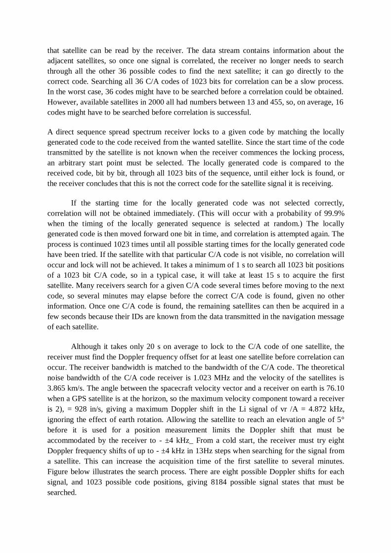
that satellite can be read by the receiver. The data stream contains information about the
adjacent satellites, so once one signal is correlated, the receiver no longer needs to search
through all the other 36 possible codes to find the next satellite; it can go directly to the
correct code. Searching all 36 C/A codes of 1023 bits for correlation can be a slow process.
In the worst case, 36 codes might have to be searched before a correlation could be obtained.
However, available satellites in 2000 all had numbers between 13 and 455, so, on average, 16
codes might have to be searched before correlation is successful.
A direct sequence spread spectrum receiver locks to a given code by matching the locally
generated code to the code received from the wanted satellite. Since the start time of the code
transmitted by the satellite is not known when the receiver commences the locking process,
an arbitrary start point must be selected. The locally generated code is compared to the
received code, bit by bit, through all 1023 bits of the sequence, until either lock is found, or
the receiver concludes that this is not the correct code for the satellite signal it is receiving.
If the starting time for the locally generated code was not selected correctly,
correlation will not be obtained immediately. (This will occur with a probability of 99.9%
when the timing of the locally generated sequence is selected at random.) The locally
generated code is then moved forward one bit in time, and correlation is attempted again. The
process is continued 1023 times until all possible starting times for the locally generated code
have been tried. If the satellite with that particular C/A code is not visible, no correlation will
occur and lock will not be achieved. It takes a minimum of 1 s to search all 1023 bit positions
of a 1023 bit C/A code, so in a typical case, it will take at least 15 s to acquire the first
satellite. Many receivers search for a given C/A code several times before moving to the next
code, so several minutes may elapse before the correct C/A code is found, given no other
information. Once one C/A code is found, the remaining satellites can then be acquired in a
few seconds because their IDs are known from the data transmitted in the navigation message
of each satellite.
Although it takes only 20 s on average to lock to the C/A code of one satellite, the
receiver must find the Doppler frequency offset for at least one satellite before correlation can
occur. The receiver bandwidth is matched to the bandwidth of the C/A code. The theoretical
noise bandwidth of the C/A code receiver is 1.023 MHz and the velocity of the satellites is
3.865 km/s. The angle between the spacecraft velocity vector and a receiver on earth is 76.10
when a GPS satellite is at the horizon, so the maximum velocity component toward a receiver
is 2), = 928 in/s, giving a maximum Doppler shift in the Li signal of vr /A = 4.872 kHz,
ignoring the effect of earth rotation. Allowing the satellite to reach an elevation angle of 5°
before it is used for a position measurement limits the Doppler shift that must be
accommodated by the receiver to - ±4 kHz_ From a cold start, the receiver must try eight
Doppler frequency shifts of up to - ±4 kHz in 13Hz steps when searching for the signal from
a satellite. This can increase the acquisition time of the first satellite to several minutes.
Figure below illustrates the search process. There are eight possible Doppler shifts for each
signal, and 1023 possible code positions, giving 8184 possible signal states that must be
searched.
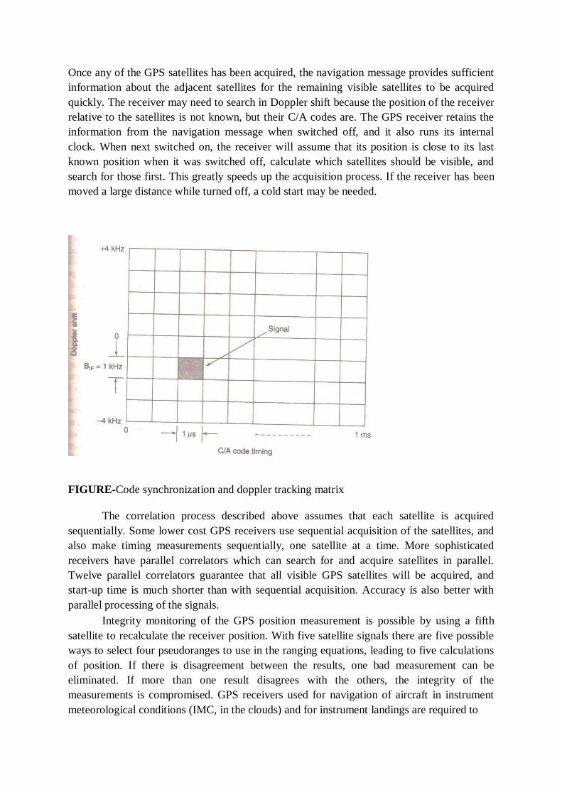
Once any of the GPS satellites has been acquired, the navigation message provides sufficient
information about the adjacent satellites for the remaining visible satellites to be acquired
quickly. The receiver may need to search in Doppler shift because the position of the receiver
relative to the satellites is not known, but their C/A codes are. The GPS receiver retains the
information from the navigation message when switched off, and it also runs its internal
clock. When next switched on, the receiver will assume that its position is close to its last
known position when it was switched off, calculate which satellites should be visible, and
search for those first. This greatly speeds up the acquisition process. If the receiver has been
moved a large distance while turned off, a cold start may be needed.
FIGURE-Code synchronization and doppler tracking matrix
The correlation process described above assumes that each satellite is acquired
sequentially. Some lower cost GPS receivers use sequential acquisition of the satellites, and
also make timing measurements sequentially, one satellite at a time. More sophisticated
receivers have parallel correlators which can search for and acquire satellites in parallel.
Twelve parallel correlators guarantee that all visible GPS satellites will be acquired, and
start-up time is much shorter than with sequential acquisition. Accuracy is also better with
parallel processing of the signals.
Integrity monitoring of the GPS position measurement is possible by using a fifth
satellite to recalculate the receiver position. With five satellite signals there are five possible
ways to select four pseudoranges to use in the ranging equations, leading to five calculations
of position. If there is disagreement between the results, one bad measurement can be
eliminated. If more than one result disagrees with the others, the integrity of the
measurements is compromised. GPS receivers used for navigation of aircraft in instrument
meteorological conditions (IMC, in the clouds) and for instrument landings are required to
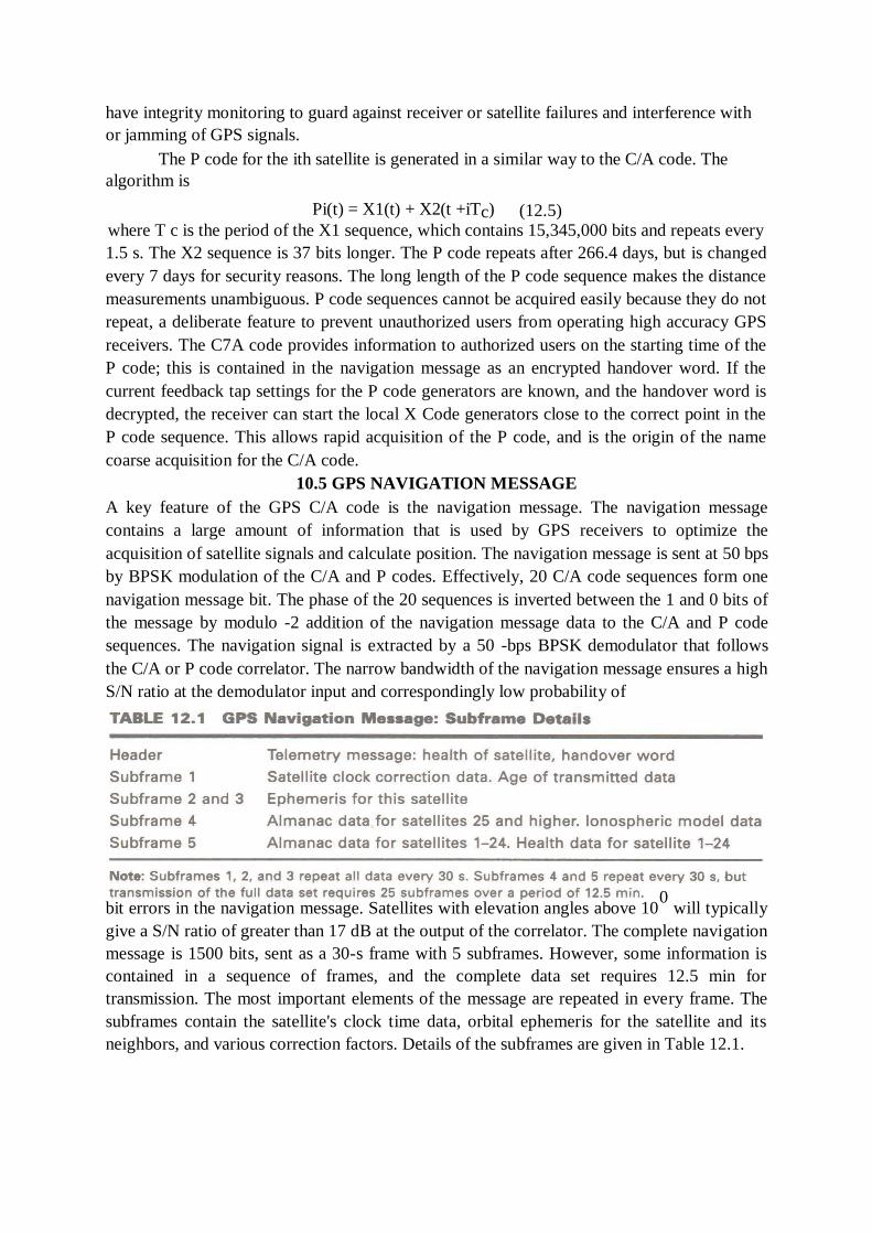
have integrity monitoring to guard against receiver or satellite failures and interference with
or jamming of GPS signals.
The P code for the ith satellite is generated in a similar way to the C/A code. The
algorithm is
Pi(t) = X1(t) + X2(t +iTc) (12.5) where T c is the period of the X1 sequence, which contains 15,345,000 bits and repeats every
1.5 s. The X2 sequence is 37 bits longer. The P code repeats after 266.4 days, but is changed
every 7 days for security reasons. The long length of the P code sequence makes the distance
measurements unambiguous. P code sequences cannot be acquired easily because they do not
repeat, a deliberate feature to prevent unauthorized users from operating high accuracy GPS
receivers. The C7A code provides information to authorized users on the starting time of the
P code; this is contained in the navigation message as an encrypted handover word. If the
current feedback tap settings for the P code generators are known, and the handover word is
decrypted, the receiver can start the local X Code generators close to the correct point in the
P code sequence. This allows rapid acquisition of the P code, and is the origin of the name
coarse acquisition for the C/A code.
10.5 GPS NAVIGATION MESSAGE
A key feature of the GPS C/A code is the navigation message. The navigation message
contains a large amount of information that is used by GPS receivers to optimize the
acquisition of satellite signals and calculate position. The navigation message is sent at 50 bps
by BPSK modulation of the C/A and P codes. Effectively, 20 C/A code sequences form one
navigation message bit. The phase of the 20 sequences is inverted between the 1 and 0 bits of
the message by modulo -2 addition of the navigation message data to the C/A and P code
sequences. The navigation signal is extracted by a 50 -bps BPSK demodulator that follows
the C/A or P code correlator. The narrow bandwidth of the navigation message ensures a high
S/N ratio at the demodulator input and correspondingly low probability of
bit errors in the navigation message. Satellites with elevation angles above 100
will typically
give a S/N ratio of greater than 17 dB at the output of the correlator. The complete navigation
message is 1500 bits, sent as a 30-s frame with 5 subframes. However, some information is
contained in a sequence of frames, and the complete data set requires 12.5 min for
transmission. The most important elements of the message are repeated in every frame. The
subframes contain the satellite's clock time data, orbital ephemeris for the satellite and its
neighbors, and various correction factors. Details of the subframes are given in Table 12.1.
The calculation of position in a GPS receiver requires very accurate knowledge of the
location of the satellite at the time that the measurements of pseudoranges are made. If the
pseudorange is measured to an accuracy of 2.4 m, we must know the satellite position to an
even greater accuracy, and that requires very accurate calculation of the GPS satellite orbits.
By comparison, the orbit of a communication satellite does not need to be known to the same
level of accuracy. As described in Chapter 2, the GPS system uses modified WGS-84 data to
define the earth's radius, Kepler's constant, and the earth's rotational rate. Data on the speed of
EM waves is taken from the International Astronomical Union. The WGS-84 data set also
includes a very detailed description of the earth's gravitational field, which is essential for
precise location of the satellites in their orbits. All of these parameters and corrections are
stored in every GPS receiver, and used in calculating position.
10.6 GPS SIGNAL LEVELS
GPS receiver antennas have low gain because they must be omnidirectional. We will assume
a worst -case gain of G = 0 dB, corresponding to an isotropic antenna. In practice, G> 0 dB in
many directions, but may fall to 0 dB in some directions. The omnidirectional antenna picks
up radiated noise from the environment, making the antenna temperature close to 273 K.
LNA temperatures can be as low as 25 K, so a system noise temperature of 273 K will be
used as a typical value. Typical GPS antennas are circularly polarized patches or quadrafilar
helices that have carefully shaped patterns that cut off quickly below 10° elevation to
minimize noise pick up from the ground. The LNA is mounted directly below or behind the
antenna to avoid the increase in noise temperature caused by lossy antenna cables.
GPS satellites have an array of helical antennas that provide gain toward the earth,
and 10 W transmitters, leading to EIRP values in the range 19 to 27 dBW. The C/A code
transmitted by the satellite is a direct sequence spread spectrum signal, so the C/N ratio in the
C/A code's RF bandwidth will be less than 0 dB. This is typical of systems that use direct
sequence spread spectrum signals. The low C/N ratio of the spread spectrum signal is
converted to a usable S/N by correlation of the code sequences, which adds a despreading
(processing) gain to the C/N ratio. The theoretical processing gain of a direct sequence spread
spectrum signal is equal to the ratio of the chip rate to the bit rate in the spreading sequence,
but losses in the correlation process always make practical gains a little lower. For the C/A
code transmitted at 1.023 Mbps and a 1 -ms correlation time, the theoretical processing gain
is 1023, or 30.1 dB. The corresponding processing gain for the P code is 40.1 dB.
The GPS receiver can pick up signals from up to 10 satellites at the same time. The
RF energy from the satellite spread spectrum transmissions adds to the noise in the receiver
as an interference term, I. For simplicity, in the following analysis we will assume that there
are 10 GPS satellites visible, that there are 9 interfering satellites generating random signals
(noise) out of which the receiver must extract the 10th signal, and that all the received signals
are of equal strength. The signals from interfering satellites are treated as random noise
because the Gold codes that they transmit have very low cross –correlation with the code
from the wanted satellite. Noise has zero cross -correlation with the wanted signal, and the
Gold codes used by GPS satellites are chosen because they closely approximate noise.

Nine interfering GPS satellites represents a worst case; in practice the number of
visible satellites varies between four and ten, and the signal strengths also vary depending on
the elevation angle of the satellite and the antenna pattern at the receiver. The worst case is
actually when a weak signal from a satellite at a low elevation angle must be extracted from
stronger signals from satellites at higher elevation angles. GPS receivers automatically select
the strongest signals for processing so that the worst case can be avoided, but if the sky is
partially blocked by obstructions, a weak signal may have to be used.
10.7 TIMING ACCURACY
The position location process requires an accurate measurement of the time of arrival of the
code sequence at the receiver. The output of the C/A code correlator is a 1 kts wide pulse that
repeats every millisecond. The accuracy with which a timing measurement can be made on a
single pulse is given by the approximate
Where St is the rms timing error, Bn, is the noise bandwidth of the RF channel, and S/N ratio
is the signal-to-noise power ratio (not in dB) for the pulse in the noise bandwidth Bn.
The S/N ratio after the correlator is
S/N = C/N + Gp — losses (12.8)
Where Gp is the correlator processing gain. For the C/A code Gp = 1023 = 30.1 dB and
S/N = —19.3 + 30.1 dB — losses
= 11.7 dB — losses
If we assume the specification value for S/N of 11.7 dB and losses of 1.7 dB, S/N = 10 dB, a
power ratio of 10. The theoretical noise bandwidth of the correlator is = 1 MHz (IF noise
bandwidth) so
A typical GPS receiver will update the display no more than twice a second, so the pulses
from the correlator can be averaged over a period of half a second, which will decrease the
rms error by V500 = 22.4 to an rms value of 14 ns, assuming randomly distributed errors.
The 14 ns rms timing error translates to an rms distance error of 4.2 m. However, four
distance measurements are needed to obtain a position measurement, so with no other errors
accounted for, the basic position measurement accuracy of the C/A code receiver is about 8.4
m (4.2 x Vi) measured as an rms value. A higher C/N ratio in the receiver will improve the
accuracy, but other errors, discussed later in Section 12.10, will lower the accuracy.
The accuracy achieved by commercial C/A code GPS receivers was better than
expected by the designers of the GPS system. Military strategists became concerned that C/A
code GPS receivers could be used to target weapons against the United States with
considerable accuracy. The U.S. Department of Defense (DOD) introduces selective
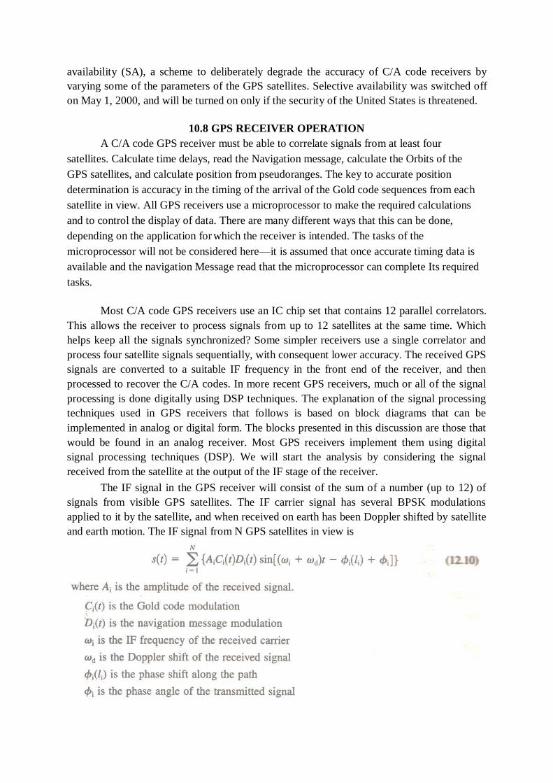
availability (SA), a scheme to deliberately degrade the accuracy of C/A code receivers by
varying some of the parameters of the GPS satellites. Selective availability was switched off
on May 1, 2000, and will be turned on only if the security of the United States is threatened.
10.8 GPS RECEIVER OPERATION
A C/A code GPS receiver must be able to correlate signals from at least four
satellites. Calculate time delays, read the Navigation message, calculate the Orbits of the
GPS satellites, and calculate position from pseudoranges. The key to accurate position
determination is accuracy in the timing of the arrival of the Gold code sequences from each
satellite in view. All GPS receivers use a microprocessor to make the required calculations
and to control the display of data. There are many different ways that this can be done,
depending on the application for which the receiver is intended. The tasks of the
microprocessor will not be considered here—it is assumed that once accurate timing data is
available and the navigation Message read that the microprocessor can complete Its required
tasks.
Most C/A code GPS receivers use an IC chip set that contains 12 parallel correlators.
This allows the receiver to process signals from up to 12 satellites at the same time. Which
helps keep all the signals synchronized? Some simpler receivers use a single correlator and
process four satellite signals sequentially, with consequent lower accuracy. The received GPS
signals are converted to a suitable IF frequency in the front end of the receiver, and then
processed to recover the C/A codes. In more recent GPS receivers, much or all of the signal
processing is done digitally using DSP techniques. The explanation of the signal processing
techniques used in GPS receivers that follows is based on block diagrams that can be
implemented in analog or digital form. The blocks presented in this discussion are those that
would be found in an analog receiver. Most GPS receivers implement them using digital
signal processing techniques (DSP). We will start the analysis by considering the signal
received from the satellite at the output of the IF stage of the receiver.
The IF signal in the GPS receiver will consist of the sum of a number (up to 12) of
signals from visible GPS satellites. The IF carrier signal has several BPSK modulations
applied to it by the satellite, and when received on earth has been Doppler shifted by satellite
and earth motion. The IF signal from N GPS satellites in view is
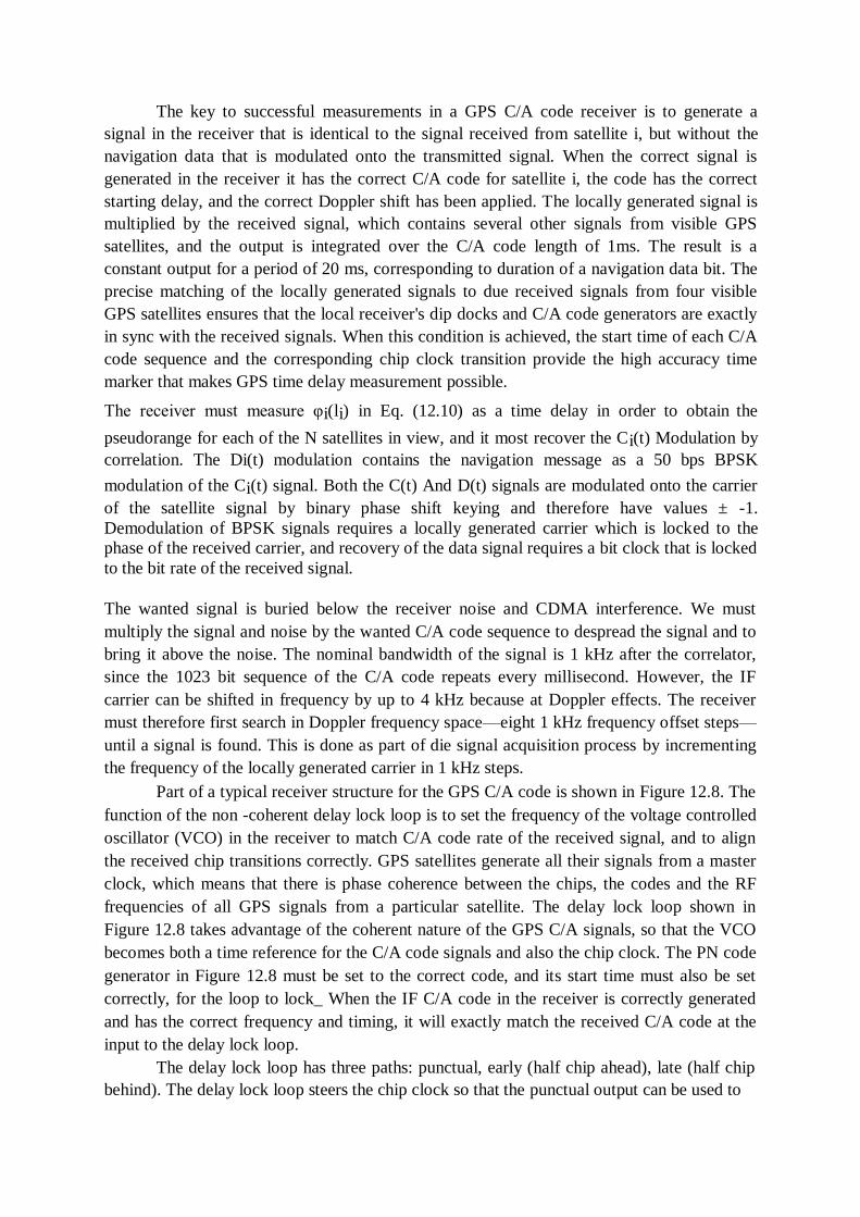
The key to successful measurements in a GPS C/A code receiver is to generate a
signal in the receiver that is identical to the signal received from satellite i, but without the
navigation data that is modulated onto the transmitted signal. When the correct signal is
generated in the receiver it has the correct C/A code for satellite i, the code has the correct
starting delay, and the correct Doppler shift has been applied. The locally generated signal is
multiplied by the received signal, which contains several other signals from visible GPS
satellites, and the output is integrated over the C/A code length of 1ms. The result is a
constant output for a period of 20 ms, corresponding to duration of a navigation data bit. The
precise matching of the locally generated signals to due received signals from four visible
GPS satellites ensures that the local receiver's dip docks and C/A code generators are exactly
in sync with the received signals. When this condition is achieved, the start time of each C/A
code sequence and the corresponding chip clock transition provide the high accuracy time
marker that makes GPS time delay measurement possible.
The receiver must measure φi(li) in Eq. (12.10) as a time delay in order to obtain the
pseudorange for each of the N satellites in view, and it most recover the Ci(t) Modulation by
correlation. The Di(t) modulation contains the navigation message as a 50 bps BPSK
modulation of the Ci(t) signal. Both the C(t) And D(t) signals are modulated onto the carrier
of the satellite signal by binary phase shift keying and therefore have values ± -1.
Demodulation of BPSK signals requires a locally generated carrier which is locked to the
phase of the received carrier, and recovery of the data signal requires a bit clock that is locked
to the bit rate of the received signal.
The wanted signal is buried below the receiver noise and CDMA interference. We must
multiply the signal and noise by the wanted C/A code sequence to despread the signal and to
bring it above the noise. The nominal bandwidth of the signal is 1 kHz after the correlator,
since the 1023 bit sequence of the C/A code repeats every millisecond. However, the IF
carrier can be shifted in frequency by up to 4 kHz because at Doppler effects. The receiver
must therefore first search in Doppler frequency space—eight 1 kHz frequency offset steps—
until a signal is found. This is done as part of die signal acquisition process by incrementing
the frequency of the locally generated carrier in 1 kHz steps.
Part of a typical receiver structure for the GPS C/A code is shown in Figure 12.8. The
function of the non -coherent delay lock loop is to set the frequency of the voltage controlled
oscillator (VCO) in the receiver to match C/A code rate of the received signal, and to align
the received chip transitions correctly. GPS satellites generate all their signals from a master
clock, which means that there is phase coherence between the chips, the codes and the RF
frequencies of all GPS signals from a particular satellite. The delay lock loop shown in
Figure 12.8 takes advantage of the coherent nature of the GPS C/A signals, so that the VCO
becomes both a time reference for the C/A code signals and also the chip clock. The PN code
generator in Figure 12.8 must be set to the correct code, and its start time must also be set
correctly, for the loop to lock_ When the IF C/A code in the receiver is correctly generated
and has the correct frequency and timing, it will exactly match the received C/A code at the
input to the delay lock loop.
The delay lock loop has three paths: punctual, early (half chip ahead), late (half chip
behind). The delay lock loop steers the chip clock so that the punctual output can be used to
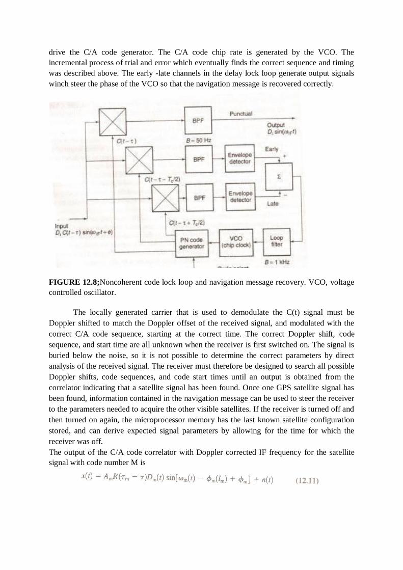
drive the C/A code generator. The C/A code chip rate is generated by the VCO. The
incremental process of trial and error which eventually finds the correct sequence and timing
was described above. The early -late channels in the delay lock loop generate output signals
winch steer the phase of the VCO so that the navigation message is recovered correctly.
FIGURE 12.8;Noncoherent code lock loop and navigation message recovery. VCO, voltage
controlled oscillator.
The locally generated carrier that is used to demodulate the C(t) signal must be
Doppler shifted to match the Doppler offset of the received signal, and modulated with the
correct C/A code sequence, starting at the correct time. The correct Doppler shift, code
sequence, and start time are all unknown when the receiver is first switched on. The signal is
buried below the noise, so it is not possible to determine the correct parameters by direct
analysis of the received signal. The receiver must therefore be designed to search all possible
Doppler shifts, code sequences, and code start times until an output is obtained from the
correlator indicating that a satellite signal has been found. Once one GPS satellite signal has
been found, information contained in the navigation message can be used to steer the receiver
to the parameters needed to acquire the other visible satellites. If the receiver is turned off and
then turned on again, the microprocessor memory has the last known satellite configuration
stored, and can derive expected signal parameters by allowing for the time for which the
receiver was off.
The output of the C/A code correlator with Doppler corrected IF frequency for the satellite
signal with code number M is
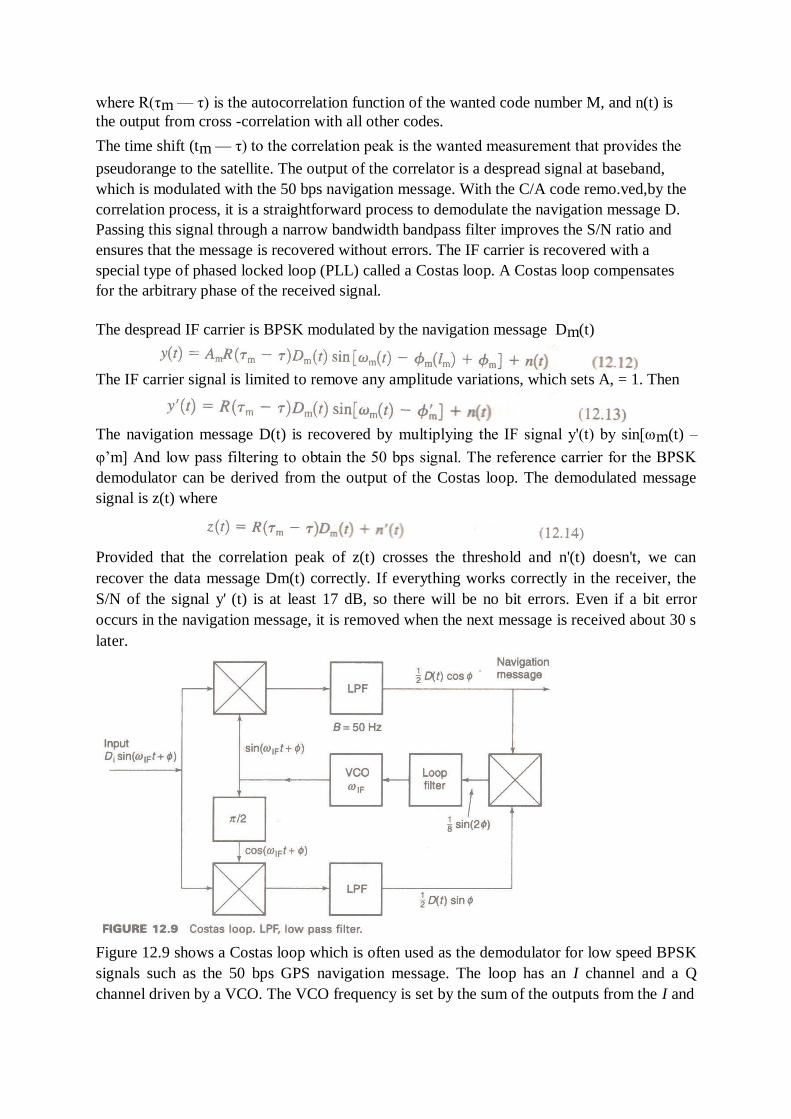
where R(τm — τ) is the autocorrelation function of the wanted code number M, and n(t) is
the output from cross -correlation with all other codes.
The time shift (tm — τ) to the correlation peak is the wanted measurement that provides the
pseudorange to the satellite. The output of the correlator is a despread signal at baseband,
which is modulated with the 50 bps navigation message. With the C/A code remo.ved,by the
correlation process, it is a straightforward process to demodulate the navigation message D.
Passing this signal through a narrow bandwidth bandpass filter improves the S/N ratio and
ensures that the message is recovered without errors. The IF carrier is recovered with a
special type of phased locked loop (PLL) called a Costas loop. A Costas loop compensates
for the arbitrary phase of the received signal.
The despread IF carrier is BPSK modulated by the navigation message Dm(t)
The IF carrier signal is limited to remove any amplitude variations, which sets A, = 1. Then
The navigation message D(t) is recovered by multiplying the IF signal y'(t) by sin[ωm(t) –
φ‘m] And low pass filtering to obtain the 50 bps signal. The reference carrier for the BPSK
demodulator can be derived from the output of the Costas loop. The demodulated message
signal is z(t) where
Provided that the correlation peak of z(t) crosses the threshold and n'(t) doesn't, we can
recover the data message Dm(t) correctly. If everything works correctly in the receiver, the
S/N of the signal y' (t) is at least 17 dB, so there will be no bit errors. Even if a bit error
occurs in the navigation message, it is removed when the next message is received about 30 s
later.
Figure 12.9 shows a Costas loop which is often used as the demodulator for low speed BPSK
signals such as the 50 bps GPS navigation message. The loop has an I channel and a Q
channel driven by a VCO. The VCO frequency is set by the sum of the outputs from the I and
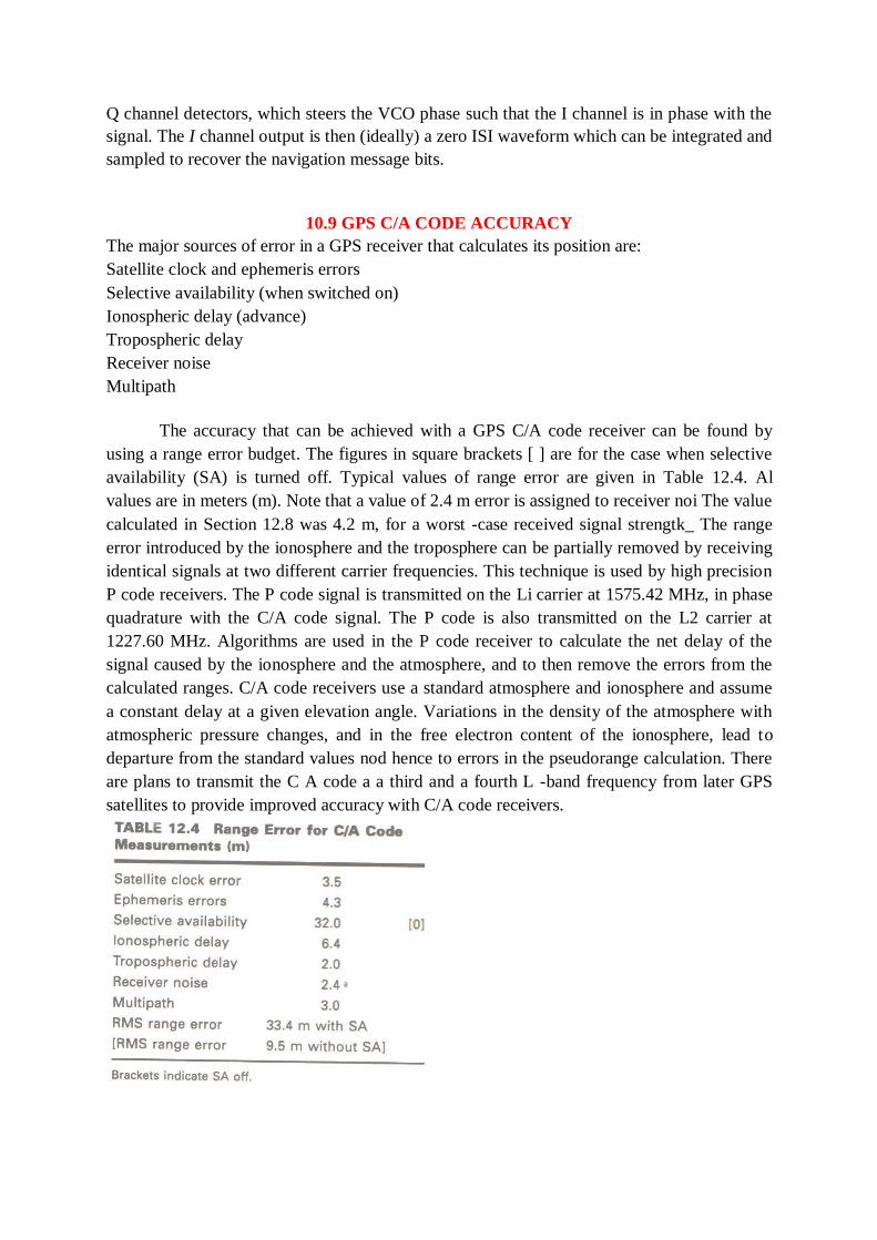
Q channel detectors, which steers the VCO phase such that the I channel is in phase with the
signal. The I channel output is then (ideally) a zero ISI waveform which can be integrated and
sampled to recover the navigation message bits.
10.9 GPS C/A CODE ACCURACY
The major sources of error in a GPS receiver that calculates its position are:
Satellite clock and ephemeris errors
Selective availability (when switched on)
Ionospheric delay (advance)
Tropospheric delay
Receiver noise
Multipath
The accuracy that can be achieved with a GPS C/A code receiver can be found by
using a range error budget. The figures in square brackets [ ] are for the case when selective
availability (SA) is turned off. Typical values of range error are given in Table 12.4. Al
values are in meters (m). Note that a value of 2.4 m error is assigned to receiver noi The value
calculated in Section 12.8 was 4.2 m, for a worst -case received signal strengtk_ The range
error introduced by the ionosphere and the troposphere can be partially removed by receiving
identical signals at two different carrier frequencies. This technique is used by high precision
P code receivers. The P code signal is transmitted on the Li carrier at 1575.42 MHz, in phase
quadrature with the C/A code signal. The P code is also transmitted on the L2 carrier at
1227.60 MHz. Algorithms are used in the P code receiver to calculate the net delay of the
signal caused by the ionosphere and the atmosphere, and to then remove the errors from the
calculated ranges. C/A code receivers use a standard atmosphere and ionosphere and assume
a constant delay at a given elevation angle. Variations in the density of the atmosphere with
atmospheric pressure changes, and in the free electron content of the ionosphere, lead to
departure from the standard values nod hence to errors in the pseudorange calculation. There
are plans to transmit the C A code a a third and a fourth L -band frequency from later GPS
satellites to provide improved accuracy with C/A code receivers.
The range error shown in Table 12.4 is for one satellite—earth path, for the pseudo-
range that is calculated from the timing measurements using the receiver clock_ However,
four pseudorange measurements are needed to make a position determination. Thus the
position location output of the GPS receiver combines four path errors, which are not
necessarily equal because of the geometry of the satellites in the sky and the different signal
strengths at the receiver input. Receiver position is calculated in (x, y, z) coordinates, and the
errors in x, y, and z depend on the elevation angle of satellites, the satellite geometry, and the
other parameters in the error budget. The calculated position will have different levels of
error in the x, y, and z directions. To account for these differences several dilution of
precision factors (DOP) are defined. A DOP factor multiplies the basic position measurement
error to give a larger error caused by the particular DOP effect.
Dilution of Precision: HDOP, VDOP, and GDOP
Horizontal dilution of precision is one of the most important DOP factors for most
GPS users. It provides an error metric for the x and y directions, in the horizontal plane. A
typical HDOP value is 1.5, and it is often the smallest of the DOPs. Horizontal measurement
error for a C/A code receiver is typically 14.3 m with SA off ( 1DR_MS) and 50 m with SA
on (1DRMS). GPS practice uses 2DRMS as the quantifier for accuracy in position
determination giving a 2DRMS accuracy of 28.6m with SA off_ The 2DRMS accuracy
figure means that 95% of all measurements yield a position within 28.6 m of the true location
of the GPS receiver, in this example.
There are many DOP factors in GPS. The more important ones are horizontal dilution of
precision, HDOP, vertical dilution of precision, VDOR and geometric dilution of precision,
GDOP. Other DOPs include position dilution of precision, PDOP, and time dilution of
precision, TDOP. In general, VDOP and GDOP are most likely to degrade the accuracy of
GPS position measurements. VDOP accounts for loss of accuracy in the vertical direction
caused by the angles at which the satellites being used for the position measurement are seen
in the sky. If the satellites are all close to the horizon, the angles between the satellites and the
receiver are all similar and VDOP can be large. In the worst possible case, if all the satellites
were at the horizon, it would be impossible to make an accurate measurement in the vertical
direction. A change in range to at least one satellite must occur when the receiver is moved,
otherwise the receiver cannot detect that change. If all the satellites are at the horizon, no
range change occurs for vertical movement of the receiver and consequently vertical accuracy
is very poor. Similarly, if all the satellites were clustered directly overhead, HDOP would be
large. VDOP is important in aircraft position measurements, where height above the ground
is a critical factor, especially when landing. C/A code receivers suffer from significant VDOP
and cannot provide sufficient vertical accuracy for automated landing of aircraft. C/A code
GPS receivers cannot guarantee sufficient vertical accuracy unless operated in a differential
GPS mode. The GPS satellites are configured in orbit to minimize the probability that a DOP
can become large, by arranging the orbits to provide clusters of four satellites with suitable
spacings in the sky. However, if the receiver's view of the sky is restricted, for example, by
buildings, the geometry for the position calculation may not be ideal and GDOP can become
large. This causes all the other DOP values to increase. Aircraft, and ships at sea always have
a clear view of the sky, but automobiles often do not. C/A code receivers may revert to two-
dimensional measurements (x and y) using three satellites when the sky is obstructed.
10.10 DIFFERENTIAL GPS
The accuracy of GPS measurements can be increased considerably by using
differential GPS (DGPS) techniques. There are several forms of DGPS, all of which are
intended to increase the accuracy of a basic GPS position measurement, and to remove the
effects of selective availability. A second, fixed, GPS receiver at a reference station is always
required in a differential GPS system. In the simplest forms of DGPS, a second GPS receiver
at a known position continuously calculates its position using the GPS C/A code. The
calculated (x,y, z) location is compared to the known location of the station and the
differences in x, y, and z are sent by a radio telemetry link to the first GPS receiver. The
accuracy of the C/A code position measurement can be increased from 100 m to about 10 m,
with SA in effect, but this technique works well only if the two stations are close together and
use the same four satellites for the position calculation.
In a more sophisticated form of differential GPS, the monitoring station at a known
location measures the error in pseudorange to each satellite that is visible at its location, and
telemeters the error values to users in that area. This allows other GPS users to select which
satellites they want to observe, and extends the area over which the DGPS system can
operate. The accuracy of a C/A code measurement can be increased to 5 m for receivers
within 10 km of the reference station and to 10 m for receivers within 500 km of the
reference station.
The most accurate forms of differential GPS use the relative phase of the many signals
in the GPS transmissions to increase the accuracy of the timing measurements. Suppose that
you could count the number of cycles of the 1575 MHz Li carrier wave between a satellite
and a GPS receiver, and that the GPS satellites are stationary for the length of time it takes to
make the count at two separate locations. The wavelength of the L1 carrier is 0.19043 m, so
movement of the receiver by 0.01 m directly away from the satellite would change the phase
angle of the received wave by 18.9°. If the total number of cycles between the satellite and
the receiver is known, and fractional cycles are measured with a phase resolution of 20°, the
true distance to the satellite can be found to 0.01 m accuracy. In principle, measurements
which compare the phase angle of the received Li carriers from several GPS satellites could
therefore be used to detect receiver movements at the centimeter level. This is called
differential phase or kinematic DGPS.
The obvious difficulty is that we cannot count the number of cycles of the Li carrier between
the satellite and the receiver. However, we can make phase measurements and time of arrival
comparisons for various GPS signals at two different locations and resolve motion between
the two locations. If one of the receivers is a fixed reference station, it is then possible to
locate the second GPS receiver very accurately with respect to that fixed location. This
technique is valuable in land surveying, for example, where a reference station can be set up
at a known location, such as the corner of a plot of land, and the position of the plot boundary
relative to that point can be measured. The same technique can be used to find the position of
an aircraft relative to an airport runway so that a precision approach path can be established.
The difficulty with DGPS phase comparison measurements is that the L1 carrier has cycles
which repeat every 0.19043 m, and one cycle is identical to the next. This creates range
ambiguity which must be resolved by reference to the wavelengths of other signals. The
10.23 MHz P code transmission of the Li carrier has a P code chip length 1 in space of
29.326 m, which is 154 cycles of the Li carrier. The ambiguity of the carrier waveform can be
resolved within the 29.326 m length of a P code chip by comparison of the time of arrival of a
particular cycle of the Li carrier with the time since the start of the P code chip. Similar
ambiguity resolution for the 29-m P code chips is possible using the length of the C/A code
chip and the C/A code sequence. The length of a C/A code chip at 1.023 MHz is 293.255 m,
and the length of a C/A code sequence is 293.255 km.
When ambiguity resolution is applied using all of these waveforms, very small
movements of the receiver can be detected and ambiguity out to 293 km can be removed.
Aircraft flight paths have been tracked to an accuracy of 2 cm over distances of tens of
kilometres using phase comparison DGPS techniques.
This explanation of kinematic differential GPS is oversimplified, because the satellites
are moving and measurements over a considerable Time are required to resolve ambiguity to
the centimeter level. The P code can be used for real-time differential measurements without
knowledge of P code itself, because only a comparison of the time of arrival of the code bits
is required. Selective availability is not applied to the P code, so differential measurements
made with the P code cannot be affected by SA. In the Wide Area Augmentation System
(WAAS) developed by the FAA for aircraft Flying in North America, 24 WAAS receive
stations continuously monitor their position as calculated from the C/A codes of all visible
satellites in the GPS system. The stations also use the P code transmissions to make accurate
differential measurements of the pseudorange to each visible satellite. The actual position of
the WAAS stations is known very accurately from prior survey data, so each WAAS station
can calculate the error in the pseudorange to each visible satellite. The 24 WAAS stations
send their data to a central station with an uplink to a GEO satellite. The central station
validates the data, combines all the information, and sends a sequence of pseudorange
correction data to all GPS users via the satellite. The central station also determines whether
any of the data is in error, and sends a warning signal called an integrity message to instruct
aircraft not to use the GPS system, or a particular satellite, because the data are not reliable.
This is an essential part of the FAA strategy for using GPS as the primary means of aircraft
navigation. If the aircraft is relying on GPS information alone to determine its position, that
information must have a very high reliability.
The WAAS GEO satellite transmits signals which are in a similar format to the L1
signals transmitted by a GPS satellite. A conventional GPS receiver with suitable software
can extract the pseudorange error values from the WAAS satellite transmission and obtain
markedly improved accuracy in its position determination. Thus no hardware changes are
needed to convert a GPS receiver to use WAAS data. The GEO satellite can also be used to
augment GPS satellites for position measurements, since it radiates the same signal format.
The calculation of pseudorange error from the P code sequence, rather than (x,y,z) position
data error from the C/A code, significantly increases the accuracy of the WAAS DGPS
system.
Eventually, it seems probable that local area augmentation systems (LAAS) Using
differential GPS will be established at many airports to replace or augment existing ILS
precision approach systems. Advanced LAAS DGPS systems have been demonstrated to
achieve better than 1-m accuracy in three dimensions, with update rates sufficiently fait to
control a passenger aircraft. This is sufficient to allow DGPS position data to be coupled to
the aircraft autopilot so that blind landings can be made automatically in zero visibility
conditions. Several demonstrations of autoland using DGPS were made in the late 1990s
using Boeing 737 and 757 aircraft.
Aircraft used by overnight delivery companies will likely be fitted with GPS big landing
systems first, since cargo aircraft are subject to fewer restrictions than passenger aircraft and
overnight delivery is subject to delays when airports are closed by low viability weather.
Typically, a good autoland system fitted to a large aircraft can achieve more consistent
landings than a skilled pilot, so autoland may eventually become as comma for landings as
autopilot use is for en route operation. Weather may eventually be less of a factor in causing
delays to passenger aircraft arrivals and departures.
TEXT BOOKS:
1. Satellite communications-Timothy Pratt, Charles Bostian and Jeremy Allnutt, WSE,
Wiley Publications, 2nd
Edition,2003. 2. Satellite communications Engineering-Wilbur L.Pritchard, Robert A Nelson and
Henri G.Suyderhoud, 2nd
Edition, Pearson Publications, 2003. REFERENCES:
1. Satellite communications - Design Principles-M.Richharia, BS Publications, 2nd
Edition, 2003.

Chapter 11: SATELLITE APPLICATIONS
11.1 INTELSAT Series:
INTELSAT stands for International Telecommunications Satellite. The
organization was created in 1964 and currently has over 140 member countries and more than
40 investing entities (see http://www.intelsat.com/ for more details).
In July 2001 INTELSAT became a private company and in May 2002 the company
began providing end-to-end solutions through a network of teleports, leased fiber, and points of
presence (PoPs) around the globe.
Starting with the Early Bird satellite in 1965, a succes- sion of satellites has been
launched at intervals of a few years. Figure 1.1 illustrates the evolution of some of the
INTELSAT satellites. As the figure shows, the capacity, in terms of number of voice channels,
increased dramatically with each succeeding launch, as well as the design lifetime.
These satellites are in geostationary orbit, meaning that they appear to be stationary in
relation to the earth. At this point it may be noted that geosta-tionary satellites orbit in the
earth‘s equatorial plane and their position is specified by their longitude.
For international traffic, INTELSAT covers three main regions—the Atlantic Ocean
Region (AOR), the Indian Ocean Region (IOR), and the Pacific Ocean Region (POR) and what
is termed Intelsat America’s Region.
For the ocean regions the satellites are positioned in geostationary orbit above the
particular ocean, where they provide a transoceanic telecommunications
route. For example, INTELSAT satellite 905 is positioned at 335.5° east longitude. The
INTELSAT VII-VII/A series was launched over a period from October
1993 to June 1996. The construction is similar to that for the V and VA/VB series, shown in
Fig. in that the VII series has solar sails rather than a cylindrical body.
The VII series was planned for service in the POR and also for some of the less
demanding services in the AOR. The antenna beam coverage is appropriate for that of the
POR. Figure 1.3 shows the antenna beam footprints for the C-band hemispheric cover- age and
zone coverage, as well as the spot beam coverage possible with the Ku-band antennas (Lilly,
1990; Sachdev et al., 1990). When used
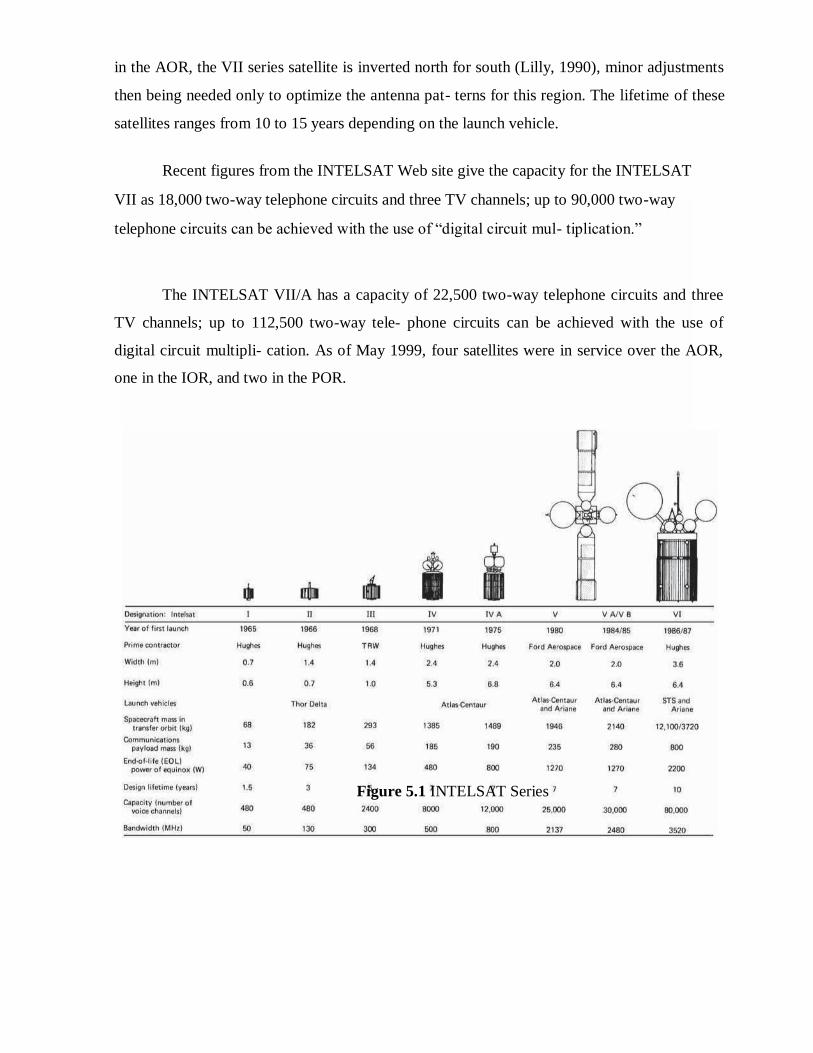
in the AOR, the VII series satellite is inverted north for south (Lilly, 1990), minor adjustments
then being needed only to optimize the antenna pat- terns for this region. The lifetime of these
satellites ranges from 10 to 15 years depending on the launch vehicle.
Recent figures from the INTELSAT Web site give the capacity for the INTELSAT
VII as 18,000 two-way telephone circuits and three TV channels; up to 90,000 two-way
telephone circuits can be achieved with the use of ―digital circuit mul- tiplication.‖
The INTELSAT VII/A has a capacity of 22,500 two-way telephone circuits and three
TV channels; up to 112,500 two-way tele- phone circuits can be achieved with the use of
digital circuit multipli- cation. As of May 1999, four satellites were in service over the AOR,
one in the IOR, and two in the POR.
Figure 5.1 INTELSAT Series

The INTELSAT VIII-VII/A series of satellites was launched over the period
February 1997 to June 1998. Satellites in this series have similar capacity as the VII/A series,
and the lifetime is 14 to 17 years.
It is standard practice to have a spare satellite in orbit on high- reliability routes (which
can carry preemptible traffic) and to have a ground spare in case of launch failure.
Thus the cost for large international schemes can be high; for example, series IX,
described later, represents a total investment of approximately $1 billion.
11.2 INSAT:
INSAT or the Indian National Satellite System is a series of multipurpose geo-
stationary satellites launched by ISRO to satisfy the telecommunications, broadcasting,
meteorology, and search and rescue
operations.
Commissioned in 1983, INSAT is the largest domestic communication system in the Asia Pacific Region. It is a joint venture of the Department of Space, Department of Telecommunications, India Meteorological Department,
Figure 5.2 Region of glob
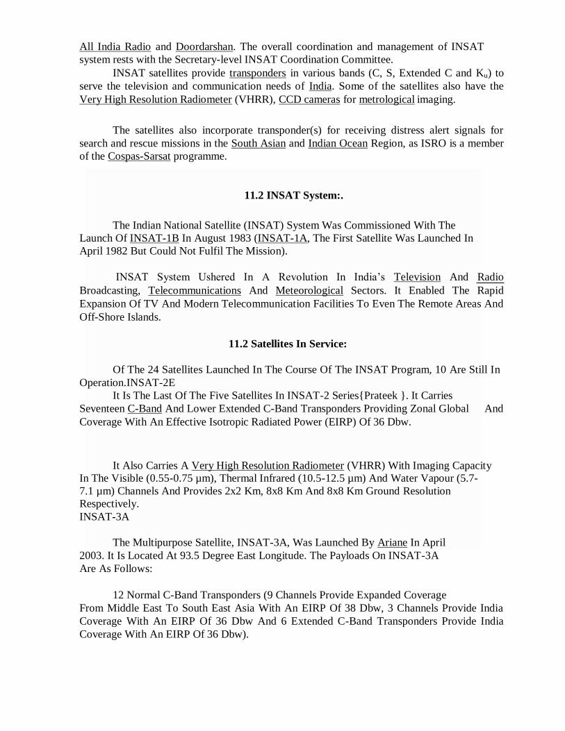
All India Radio and Doordarshan. The overall coordination and management of INSAT
system rests with the Secretary-level INSAT Coordination Committee.
INSAT satellites provide transponders in various bands (C, S, Extended C and Ku) to
serve the television and communication needs of India. Some of the satellites also have the
Very High Resolution Radiometer (VHRR), CCD cameras for metrological imaging.
The satellites also incorporate transponder(s) for receiving distress alert signals for
search and rescue missions in the South Asian and Indian Ocean Region, as ISRO is a member
of the Cospas-Sarsat programme.
11.2 INSAT System:.
The Indian National Satellite (INSAT) System Was Commissioned With The
Launch Of INSAT-1B In August 1983 (INSAT-1A, The First Satellite Was Launched In
April 1982 But Could Not Fulfil The Mission).
INSAT System Ushered In A Revolution In India‘s Television And Radio
Broadcasting, Telecommunications And Meteorological Sectors. It Enabled The Rapid
Expansion Of TV And Modern Telecommunication Facilities To Even The Remote Areas And
Off-Shore Islands.
11.2 Satellites In Service:
Of The 24 Satellites Launched In The Course Of The INSAT Program, 10 Are Still In
Operation.INSAT-2E
It Is The Last Of The Five Satellites In INSAT-2 Series{Prateek }. It Carries
Seventeen C-Band And Lower Extended C-Band Transponders Providing Zonal Global
Coverage With An Effective Isotropic Radiated Power (EIRP) Of 36 Dbw.
And
It Also Carries A Very High Resolution Radiometer (VHRR) With Imaging Capacity
In The Visible (0.55-0.75 µm), Thermal Infrared (10.5-12.5 µm) And Water Vapour (5.7-
7.1 µm) Channels And Provides 2x2 Km, 8x8 Km And 8x8 Km Ground Resolution
Respectively.
INSAT-3A
The Multipurpose Satellite, INSAT-3A, Was Launched By Ariane In April
2003. It Is Located At 93.5 Degree East Longitude. The Payloads On INSAT-3A
Are As Follows:
12 Normal C-Band Transponders (9 Channels Provide Expanded Coverage
From Middle East To South East Asia With An EIRP Of 38 Dbw, 3 Channels Provide India
Coverage With An EIRP Of 36 Dbw And 6 Extended C-Band Transponders Provide India
Coverage With An EIRP Of 36 Dbw).

A CCD Camera Provides 1x1 Km Ground Resolution, In The Visible (0.63 - µm),
Near Infrared (0.77-0.86 µm) And Shortwave Infrared (1.55-1.70
µm) Bands.
INSAT-3D
Launched In July 2013, INSAT-3D Is Positioned At 82 Degree East Longitude.
INSAT-3D Payloads Include Imager, Sounder, Data Relay Transponder And Search & Rescue
Transponder. All The Transponders Provide Coverage Over Large Part Of The Indian Ocean
Region Covering India, Bangladesh, Bhutan,Maldives, Nepal, Seychelles, Sri Lanka And
Tanzania For Rendering Distress Alert Services
INSAT-3E
Launched In September 2003, INSAT-3E Is Positioned At 55 Degree
East
Longitude And Carries 24 Normal C-Band Transponders Provide An Edge Of Coverage EIRP
Of 37 Dbw Over India And 12 Extended C-Band Transponders Provide An Edge Of Coverage
EIRP Of 38 Dbw Over India.
KALPANA-1
KALPANA-1 Is An Exclusive Meteorological Satellite Launched By PSLV In
September 2002. It Carries Very High Resolution Radiometer And DRT Payloads To Provide
Meteorological Services. It Is Located At 74 Degree East Longitude. Its First Name Was
METSAT. It Was Later Renamed As KALPANA-1 To Commemorate Kalpana Chawla.
Edusat
Configured For Audio-Visual Medium Employing Digital Interactive Classroom
Lessons And Multimedia Content, EDUSAT Was Launched By GSLV In September 2004. Its
Transponders And Their Ground Coverage Are Specially Configured To Cater To The
Educational Requirements.
GSAT-2
Launched By The Second Flight Of GSLV In May 2003, GSAT-2 Is Located At 48
Degree East Longitude And Carries Four Normal C-Band Transponders To Provide 36 Dbw
EIRP With India Coverage, Two Ku Band Transponders With 42 Dbw EIRP Over India And
An MSS Payload Similar To Those On INSAT-3B And INSAT-3C.
INSAT-4 Series:
Figure 5.3 INSAT 4A
INSAT-4A is positioned at 83 degree East longitude along with INSAT-2E and
INSAT-3B. It carries 12 Ku band 36 MHz bandwidth transponders employing 140 W TWTAs
to provide an EIRP of 52 dBW at the edge of coverage polygon with footprint covering Indian
main land and 12 C-band 36 MHz bandwidth transponders provide an EIRP of 39 dBW at the
edge of coverage with expanded radiation patterns encompassing Indian geographical
boundary, area beyond India in southeast and northwest regions.[8] Tata Sky, a joint venture
between the TATA Group and STAR uses INSAT-4A for distributing their DTH service.
INSAT-
4A
INSAT-
4B
Glitch In INSAT 4B
China-Stuxnet Connection
INSAT-4CR
GSAT-8 / INSAT-4G
GSAT-12 /GSAT-10
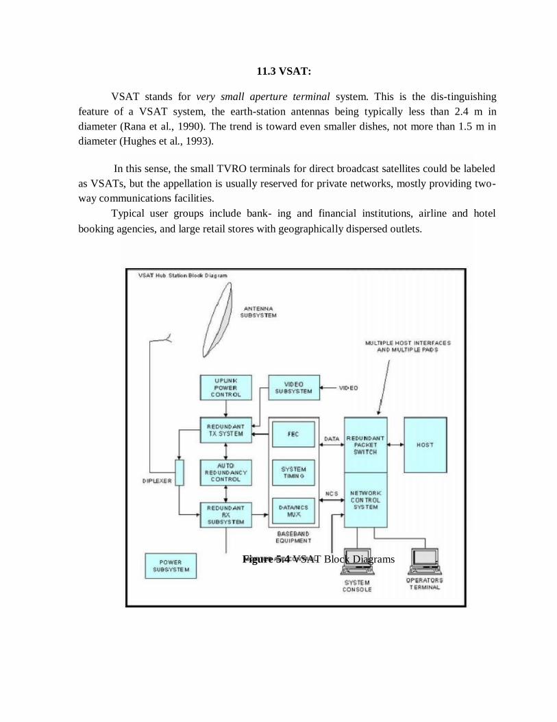
11.3 VSAT:
VSAT stands for very small aperture terminal system. This is the dis-tinguishing
feature of a VSAT system, the earth-station antennas being typically less than 2.4 m in
diameter (Rana et al., 1990). The trend is toward even smaller dishes, not more than 1.5 m in
diameter (Hughes et al., 1993).
In this sense, the small TVRO terminals for direct broadcast satellites could be labeled
as VSATs, but the appellation is usually reserved for private networks, mostly providing two-
way communications facilities.
Typical user groups include bank- ing and financial institutions, airline and hotel
booking agencies, and large retail stores with geographically dispersed outlets.
Figure 5.4 VSAT Block Diagrams
11.4 VSAT network :
The basic structure of a VSAT network consists of a hub station which provides a
broadcast facility to all the VSATs in the network and the VSATs themselves which access the
satellite in some form of multiple- access mode.
The hub station is operated by the service provider, and it may be shared among a
number of users, but of course, each user organ- ization has exclusive access to its own VSAT
network.
Time division mul- tiplex is the normal downlink mode of transmission from hub to the
VSATs, and the transmission can be broadcast for reception by all the VSATs in a network, or
address coding can be used to direct messages to selected VSATs.
A form of demand assigned multiple access (DAMA) is employed in some systems in
which channel capacity is assigned in response to the fluctuating demands of the VSATs in the
network.
Most VSAT systems operate in the Ku band, although there are some C-band systems
in existence (Rana et al., 1990).
Applications:
Supermarket shops (tills, ATM machines, stock sale updates and stock
ordering).
Chemist shops - Shoppers Drug Mart - Pharmaprix. Broadband direct to the
home. e.g. Downloading MP3 audio to audio players.
Broadband direct small business, office etc, sharing local use with many PCs.
Internet access from on board ship Cruise ships with internet cafes,
commercial shipping communications.
11.5 Mobile satellite services:
GSM:
Services and Architecture:
If your work involves (or is likely to involve) some form of wireless public
communications, you are likely to encounter the GSM standards. Initially developed to support
a standardized approach to digital cellular communications in Europe, the "Global System for
Mobile Communications" (GSM) protocols are rapidly being adopted to the next generation of
wireless telecommunications systems.
In the US, its main competition appears to be the cellular TDMA systems based on
the IS-54 standards. Since the GSM systems consist of a wide range of
components, standards, and protocols.
The GSM and its companion standard DCS1800 (for the UK, where the 900 MHz
frequencies are not available for GSM) have been developed over the last decade to allow
cellular communications systems to move beyond the limitations posed by the older analog
systems.
Analog system capacities are being stressed with more users that can be effectively
supported by the available frequency allocations. Compatibility between types of systems had
been limited, if non-existent.
By using digital encoding techniques, more users can share the same frequencies than had
been available in the analog systems. As compared to the digital cellular systems in the US
(CDMA [IS-95] and TDMA [IS-54]), the GSM market has had impressive success.
Estimates of the numbers of telephones run from 7.5 million GSM phones to .5 million
IS54 phones to .3 million for IS95.
GSM has gained in acceptance from its initial beginnings in Europe to other parts of the
world including Australia, New Zealand, countries in the Middle East and the far east. Beyond
its use in cellular frequencies (900 MHz for GSM, 1800 MHz for DCS1800), portions of the
GSM signaling protocols are finding their way into the newly developing PCS and LEO
Satellite communications systems.
While the frequencies and link characteristics of these systems differ from the standard
GSM air interface, all of these systems must deal with users roaming from one cell (or satellite
beam) to another, and bridge services to public communication networks including the Public
Switched Telephone Network (PSTN), and public data networks (PDN).
The GSM architecture includes several subsystems:
The Mobile Station (MS) -- These digital telephones include vehicle, portable and
hand-held terminals. A device called the Subscriber Identity
Module (SIM) that is basically a smart-card provides custom information about users such
as the services they've subscribed to and their identification in the network
The Base Station Sub-System (BSS) -- The BSS is the collection of devices that
support the switching networks radio interface. Major components of the BSS include the Base
Transceiver Station (BTS) that consists of the radio modems and antenna equipment.
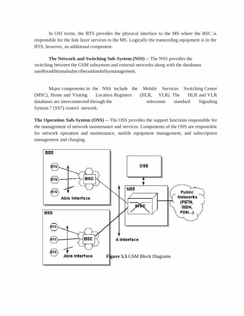
In OSI terms, the BTS provides the physical interface to the MS where the BSC is
responsible for the link layer services to the MS. Logically the transcoding equipment is in the
BTS, however, an additional component.
The Network and Switching Sub-System (NSS) -- The NSS provides the
switching between the GSM subsystem and external networks along with the databases
usedforadditionalsubscriberandmobilitymanagement.
Major components in the NSS include the Mobile Services Switching Center
(MSC), Home and Visiting Location Registers (HLR, VLR). The HLR and VLR
databases are interconnected through the telecomm standard Signaling
System 7 (SS7) control network.
The Operation Sub-System (OSS) -- The OSS provides the support functions responsible for
the management of network maintenance and services. Components of the OSS are responsible
for network operation and maintenance, mobile equipment management, and subscription
management and charging.
Figure 5.5 GSM Block Diagrams
Several channels are used in the air interface:
FCCH - the frequency correction channel - provides frequency synchronization
information in a burst
SCH - Synchronization Channel - shortly following the FCCH burst (8 bits later),
provides a reference to all slots on a given frequency
PAGCH - Paging and Access Grant Channel used for the transmission of paging
information requesting the setup of a call to a MS.
RACH - Random Access Channel - an inbound channel used by the MS to
request connections from the ground network. Since this is used for the
first access attempt by users of the network, a random access scheme is
used to aid in avoiding collisions.
CBCH - Cell Broadcast Channel - used for infrequent transmission of broadcasts by
the ground network.
BCCH - Broadcast Control Channel - provides access status information to the MS.
The information provided on this channel is used by the MS to determine whether or
not to request a transition to a new cell
FACCH - Fast Associated Control Channel for the control of handovers
TCH/F - Traffic Channel, Full Rate for speech at 13 kbps or data at 12, 6, or 3.6
kbps
TCH/H - Traffic Channel, Half Rate for speech at 7 kbps, or data at 6 or 3.6 kbps
Mobility Management:
One of the major features used in all classes of GSM networks (cellular, PCS and
Satellite) is the ability to support roaming users. Through the control signaling network, the
MSCs interact to locate and connect to users throughout the network.
"Location Registers" are included in the MSC databases to assist in the role of
determining how, and whether connections are to be made to roaming users. Each user of a
GSM MS is assigned a Home Location Register (HLR) that is used to contain the user's
location and subscribed services.
Difficulties facing the operators can include;
a. Remote/Rural Areas. To service remote areas, it is often economically unfeasible to
provide backhaul facilities (BTS to BSC) via terrestrial lines (fiber/microwave).
b. Time to deploy. Terrestrial build-outs can take years to plan and
implement.
c. Areas of ‗minor‘ interest. These can include small isolated centers such as
tourist resorts, islands, mines, oil exploration sites, hydro-electric facilities.
d. Temporary Coverage. Special events, even in urban areas, can overload the
existing infrastructure.
GSM service security:
GSM was designed with a moderate level of service security. GSM uses several
cryptographic algorithms for security. The A5/1, A5/2, and A5/3 stream ciphers are used
for ensuring over-the-air voice privacy.
GSM uses General Packet Radio Service (GPRS) for data transmissions like browsing
the web. The most commonly deployed GPRS ciphers were publicly broken in 2011The
researchers revealed flaws in the commonly used GEA/1.
Global Positioning System (GPS) :
The Global Positioning System (GPS) is a satellite based navigation system that can be
used to locate positions anywhere on earth. Designed and operated by the U.S.
Department of Defense, it consists of satellites, control and
monitor stations, and receivers. GPS receivers take information transmitted from
the satellites and uses triangulation to calculate a user‘s exact location.
GPS is used on incidents in a variety of ways, such as:
To determine position locations; for example, you need to radio a
helicopter pilot the coordinates of your position location so the pilot can pick you up.
To navigate from one location to another; for example, you need to travel from a lookout
to the fire perimeter.
To create digitized maps; for example, you are assigned to plot the fire perimeter and
hot spots.
To determine distance between two points or how far you are from another
location.
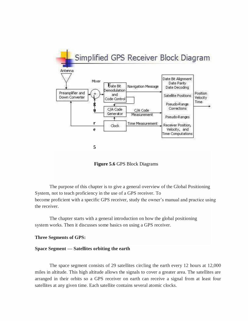
F
i
g
u
r
e
5
Figure 5.6 GPS Block Diagrams
The purpose of this chapter is to give a general overview of the Global Positioning
System, not to teach proficiency in the use of a GPS receiver. To
become proficient with a specific GPS receiver, study the owner‘s manual and practice using
the receiver.
The chapter starts with a general introduction on how the global positioning
system works. Then it discusses some basics on using a GPS receiver.
Three Segments of GPS:
Space Segment — Satellites orbiting the earth
The space segment consists of 29 satellites circling the earth every 12 hours at 12,000
miles in altitude. This high altitude allows the signals to cover a greater area. The satellites are
arranged in their orbits so a GPS receiver on earth can receive a signal from at least four
satellites at any given time. Each satellite contains several atomic clocks.

Control Segment — The control and monitoring stations
The control segment tracks the satellites and then provides them with corrected orbital
and time information. The control segment consists of five unmanned monitor stations and one
Master Control Station. The five unmanned stations monitor GPS satellite signals and then
send that information to the Master Control Station where anomalies are corrected and sent
back to the GPS satellites through ground antennas.
User Segment — The GPS receivers owned by civilians and military
The user segment consists of the users and their GPS receivers. The number of
simultaneous users is limitless.
How GPS Determines a Position:
The GPS receiver uses the following information to determine a position.
Precise location of satellites
When a GPS receiver is first turned on, it downloads orbit information from all the
satellites called an almanac. This process, the first time, can take as long as 12 minutes; but
once this information is downloaded, it is stored in the receiver‘s memory for future use.
Distance from each satellite
The GPS receiver calculates the distance from each satellite to the receiver by using the
distance formula: distance = velocity x time. The receiver already knows the velocity, which is
the speed of a radio wave or 186,000 miles per second (the speed of light).
Triangulation to determine position
The receiver determines position by using triangulation. When it receives signals from at
least three satellites the receiver should be able to calculate its approximate position (a 2D
position). The receiver needs at least four or more satellites to calculate a more accurate 3D
position.
Using a GPS Receiver :
There are several different models and types of GPS receivers. Refer to the owner‘s manual
for your GPS Receiver and practice using it to become proficient
When working on an incident with a GPS receiver it is important to:
Always have a compass and a map.
Have a GPS download cable.
Have extra batteries.
Know memory capacity of the GPS receiver to prevent loss of data,
decrease in accuracy of data,or other problems.
Use an external antennae whenever possible, especially under tree canopy,
in canyons, or while flying or driving.
Set up GPS receiver according to incident or agency standard regulation;
coordinate system.
Take notes that describe what you are saving in the receiver.
INMARSAT:
Inmarsat-Indian Maritime SATellite is still the sole IMO-mandated provider of
satellite communications for the GMDSS.
Availability for GMDSS is a minimum of 99.9%
Inmarsat has constantly and consistently exceeded this figure & Independently
audited by IMSO and reported on to IMO.
Now Inmarsat commercial services use the same satellites and network &Inmarsat A
closes at midnight on 31 December 2007 Agreed by IMO – MSC/Circ.1076. Successful
closure programme almost concluded Overseen throughout by IMSO.
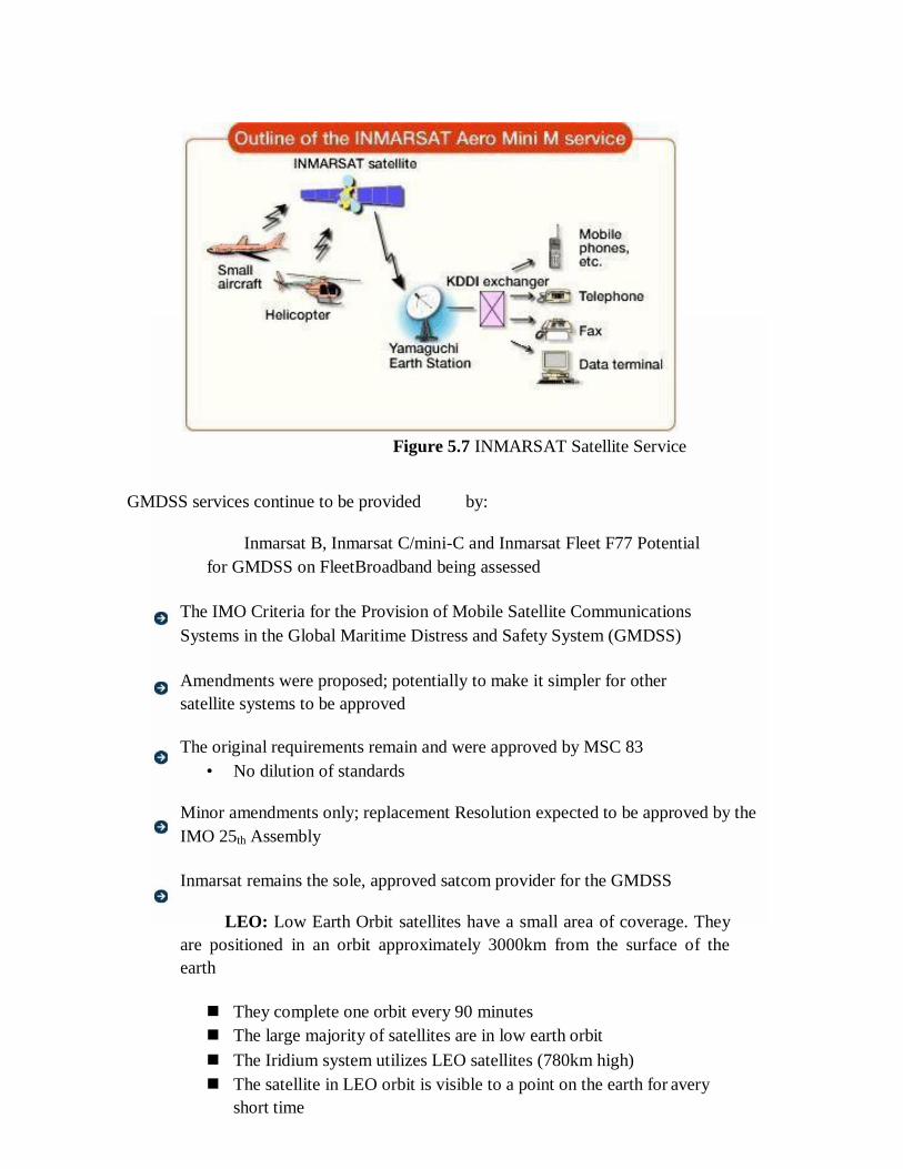
Figure 5.7 INMARSAT Satellite Service
GMDSS services continue to be provided by:
Inmarsat B, Inmarsat C/mini-C and Inmarsat Fleet F77 Potential
for GMDSS on FleetBroadband being assessed
The IMO Criteria for the Provision of Mobile Satellite Communications
Systems in the Global Maritime Distress and Safety System (GMDSS)
Amendments were proposed; potentially to make it simpler for other
satellite systems to be approved
The original requirements remain and were approved by MSC 83
• No dilution of standards
Minor amendments only; replacement Resolution expected to be approved by the
IMO 25th Assembly
Inmarsat remains the sole, approved satcom provider for the GMDSS
LEO: Low Earth Orbit satellites have a small area of coverage. They
are positioned in an orbit approximately 3000km from the surface of the
earth
They complete one orbit every 90 minutes
The large majority of satellites are in low earth orbit
The Iridium system utilizes LEO satellites (780km high)
The satellite in LEO orbit is visible to a point on the earth for avery
short time
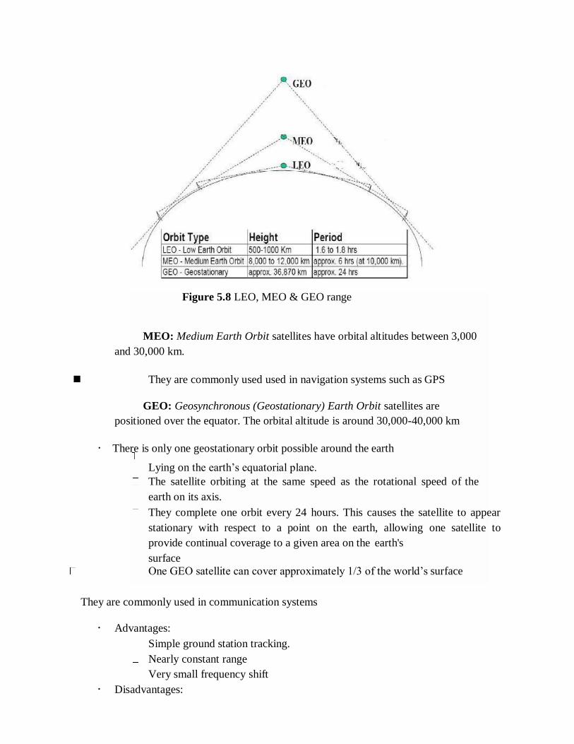
Figure 5.8 LEO, MEO & GEO range
MEO: Medium Earth Orbit satellites have orbital altitudes between 3,000
and 30,000 km.
They are commonly used used in navigation systems such as GPS
GEO: Geosynchronous (Geostationary) Earth Orbit satellites are
positioned over the equator. The orbital altitude is around 30,000-40,000 km
There is only one geostationary orbit possible around the earth
Lying on the earth‘s equatorial plane.
The satellite orbiting at the same speed as the rotational speed of the
earth on its axis.
They complete one orbit every 24 hours. This causes the satellite to appear
stationary with respect to a point on the earth, allowing one satellite to
provide continual coverage to a given area on the earth's
surface
One GEO satellite can cover approximately 1/3 of the world‘s surface
They are commonly used in communication systems
Advantages:
Simple ground station tracking.
Nearly constant range
Very small frequency shift
Disadvantages:
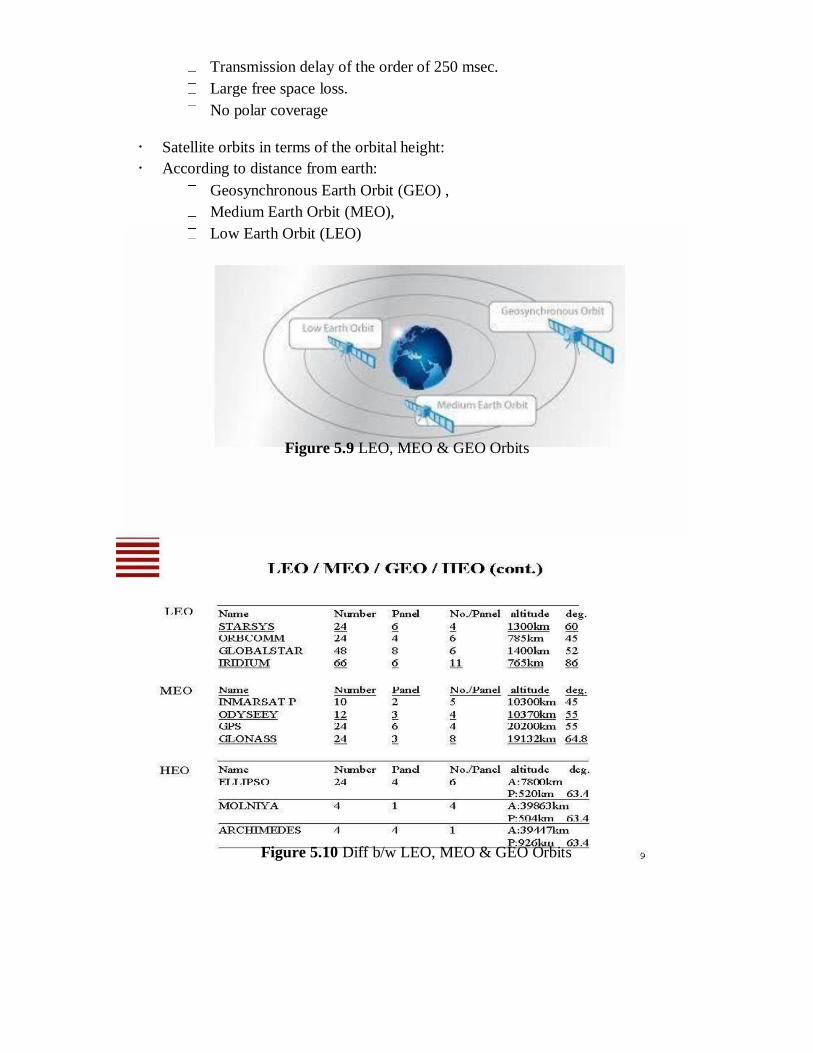
Transmission delay of the order of 250 msec.
Large free space loss.
No polar coverage
Satellite orbits in terms of the orbital height:
According to distance from earth:
Geosynchronous Earth Orbit (GEO) ,
Medium Earth Orbit (MEO),
Low Earth Orbit (LEO)
Figure 5.9 LEO, MEO & GEO Orbits
Figure 5.10 Diff b/w LEO, MEO & GEO Orbits
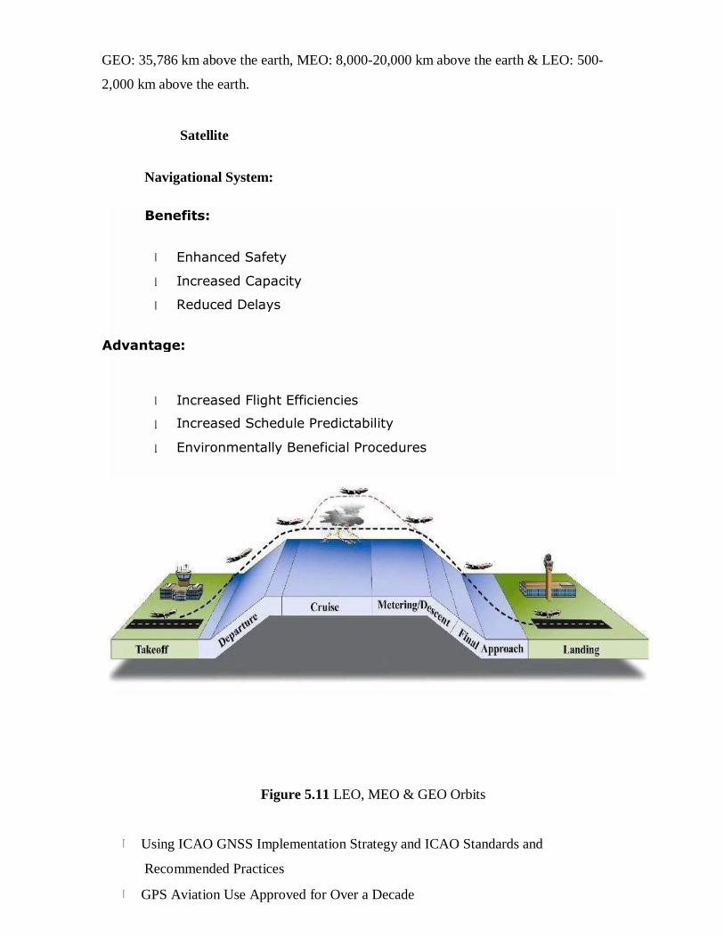
GEO: 35,786 km above the earth, MEO: 8,000-20,000 km above the earth & LEO: 500-
2,000 km above the earth.
Satellite
Navigational System:
Figure 5.11 LEO, MEO & GEO Orbits
Using ICAO GNSS Implementation Strategy and ICAO Standards and
Recommended Practices
GPS Aviation Use Approved for Over a Decade
Benefits:
Enhanced Safety
Increased Capacity
Reduced Delays
Advantage:
Increased Flight Efficiencies
Increased Schedule Predictability
Environmentally Beneficial Procedures

– Aircraft Based Augmentation Systems (ABAS) – (e.g. RAIM)
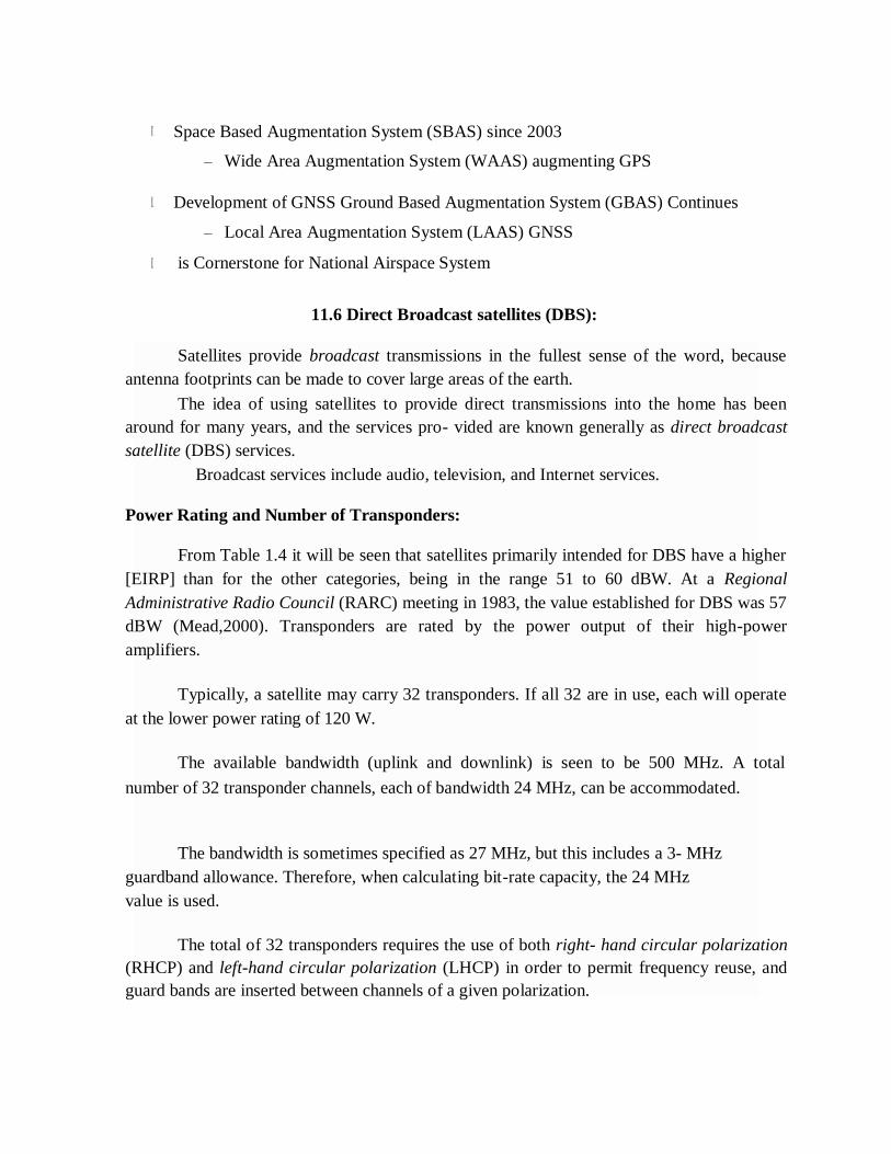
Space Based Augmentation System (SBAS) since 2003
– Wide Area Augmentation System (WAAS) augmenting GPS
Development of GNSS Ground Based Augmentation System (GBAS) Continues
– Local Area Augmentation System (LAAS) GNSS
is Cornerstone for National Airspace System
11.6 Direct Broadcast satellites (DBS):
Satellites provide broadcast transmissions in the fullest sense of the word, because
antenna footprints can be made to cover large areas of the earth.
The idea of using satellites to provide direct transmissions into the home has been
around for many years, and the services pro- vided are known generally as direct broadcast
satellite (DBS) services.
Broadcast services include audio, television, and Internet services.
Power Rating and Number of Transponders:
From Table 1.4 it will be seen that satellites primarily intended for DBS have a higher
[EIRP] than for the other categories, being in the range 51 to 60 dBW. At a Regional
Administrative Radio Council (RARC) meeting in 1983, the value established for DBS was 57
dBW (Mead,2000). Transponders are rated by the power output of their high-power
amplifiers.
Typically, a satellite may carry 32 transponders. If all 32 are in use, each will operate
at the lower power rating of 120 W.
The available bandwidth (uplink and downlink) is seen to be 500 MHz. A total
number of 32 transponder channels, each of bandwidth 24 MHz, can be accommodated.
The bandwidth is sometimes specified as 27 MHz, but this includes a 3- MHz
guardband allowance. Therefore, when calculating bit-rate capacity, the 24 MHz
value is used.
The total of 32 transponders requires the use of both right- hand circular polarization
(RHCP) and left-hand circular polarization (LHCP) in order to permit frequency reuse, and
guard bands are inserted between channels of a given polarization.
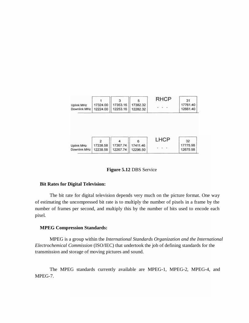
Figure 5.12 DBS Service
Bit Rates for Digital Television:
The bit rate for digital television depends very much on the picture format. One way
of estimating the uncompressed bit rate is to multiply the number of pixels in a frame by the
number of frames per second, and multiply this by the number of bits used to encode each
pixel.
MPEG Compression Standards:
MPEG is a group within the International Standards Organization and the International
Electrochemical Commission (ISO/IEC) that undertook the job of defining standards for the
transmission and storage of moving pictures and sound.
The MPEG standards currently available are MPEG-1, MPEG-2, MPEG-4, and
MPEG-7.
11.7 Direct to home Broadcast (DTH):
DTH stands for Direct-To-Home television. DTH is defined as the reception of
satellite programmes with a personal dish in an individual home.
DTH Broadcasting to home TV receivers take place in the ku band(12
GHz). This service is known as Direct To Home service.
DTH services were first proposed in India in 1996.
Finally in 2000, DTH was allowed.
The new policy requires all operators to set up earth stations in India
within 12 months of getting a license. DTH licenses in India will cost
$2.14 million and will be valid for 10 years.
Working principal of DTH is the satellite communication. Broadcaster modulates the
received signal and transmit it to the satellite in KU Band and from satellite one can receive
signal by dish and set top box.
DTH Block Diagram:
A DTH network consists of a broadcasting centre, satellites, encoders,
multiplexers, modulators and DTH receivers
The encoder converts the audio, video and data signals into the digital
format and the multiplexer mixes these signals.
It is used to provide the DTH service in high populated area A Multi Switch is
basically a box that contains signal splitters and A/B switches. A outputs of group of DTH
LNBs are connected to the A and B inputs of the Multi Switch.
Figure 5.13 DTH Service
Advantage:
DTH also offers digital quality signals which do not degrade the picture or sound
quality.
It also offers interactive channels and program guides with customers having the
choice to block out programming which they consider undesirable
One of the great advantages of the cable industry has been the ability to provide
local channels, but this handicap has been overcome by many DTH providers using
other local channels or local feeds.
The other advantage of DTH is the availability of satellite broadcast in
rural and semi-urban areas where cable is difficult to install.
11.8 Digital audio broadcast (DAB):
DAB Project is an industry-led consortium of over 300 companies
The DAB Project was launched on 10th September, 1993
In 1995 it was basically finished and became operational
There are several sub-standards of the DAB standard
o DAB-S (Satellite) – using QPSK – 40 Mb/s
o DAB-T (Terrestrial) – using QAM – 50 Mb/s
o DAB-C (Cable) – using OFDM – 24 Mb/s
These three sub-standards basically differ only in the specifications to physical
representation, modulation, transmission and reception of the signal.
the
The DAB stream consists of a series of fixed length packets which make up a
Transport Stream (TS). The packets support ‗streams‘ or ‗data sections‘.
Streams carry higher layer packets derived from an MPEG stream & Data
sections are blocks of data carrying signaling and control data.
DAB is actually a support mechanism for MPEG.& One MPEG stream needing higher
instantaneous data can ‗steal‘ capacity from another with spare capacity.
11.9 Worldspace services:
WorldSpace (Nasdaq: WRSP) is the world's only global media and entertainment
company positioned to offer a satellite radio experience to consumers in more than 130
countries with five billion people, driving 300 million cars. WorldSpace delivers the latest
tunes, trends and information from around the world and around the corner.
WorldSpace subscribers benefit from a unique combination of local programming,
original WorldSpace content and content from leading brands around the globe, including
the BBC, CNN, Virgin Radio, NDTV and RFI.
WorldSpace's satellites cover two-thirds of the globe with six beams.
Each beam is capable of delivering up to 80 channels of high quality digital audio and
multimedia programming directly to WorldSpace Satellite Radios anytime and virtually
anywhere in its coverage area. WorldSpace is a pioneer of satellite-based digital radio
services (DARS) and was instrumental in the development of the technology infrastructure
used today by XM Satellite Radio. For more information, visit Business Television (BTV)
- Adaptations for Education:
Business television (BTV) is the production and distribution, via satellite, of video
programs for closed user group audiences. It often has two-way audio interaction component
made through a simple telephone line. It is being used by many industries including brokerage
firms, pizza houses, car dealers and delivery services.
BTV is an increasingly popular method of information delivery for corporations and
institutions. Private networks, account for about 70 percent of all BTV networks. It is
estimated that by the mid-1990s BTV has the potential to grow to a $1.6 billion market in
North America with more and more Fortune 1,000 companies getting involved.
Institution updates, news, training, meetings and other events can be broadcast live to
multiple locations. The expertise of the best instructors can be delivered to thousands of
people without requiring trainers to go to the site. Information can be disseminated to all
employees at once, not just a few at a time. Delivery to the workplace at low cost provides the
access to training that has been denied lower level employees. It may be the key to re-training
America's work force.
Television has been used to deliver training and information within businesses for
more than 40 years. Its recent growth began with the introduction
of the video cassette in the early 1970s. Even though most programming is produced for
video cassette distribution, business is using BTV to provide efficient delivery of specialized
programs via satellite.
The advent of smaller receiving stations - called very small aperture terminals
(VSATs) has made private communication networks much more economical to operate. BTV
has a number of tangible benefits, such as reducing travel, immediate delivery of time-critical
messages, and eliminating cassette duplication and distribution hassles.
The programming on BTV networks is extremely cost-effective compared to seminar
fees and downtime for travel. It is an excellent way to get solid and current information very
fast. Some people prefer to attend seminars and conferences where they can read, see, hear
and ask questions in person. BTV provides yet another piece of the education menu and is
another way to provide professional development.
A key advantage is that its format allows viewers to interact with presenters by
telephone, enabling viewers to become a part of the program. The satellite effectively places
people in the same room, so that sales personnel in the field can learn about new products at
the same time.
Speed of transmission may well be the competitive edge which some firms need as
they introduce new products and services. BTV enables employees in many locations to focus
on common problems or issues that might develop into crises without quick communication
and resolution.
BTV networks transmit information every business day on a broad range of topics,
and provide instructional courses on various products, market trends, selling and motivation.
Networks give subscribers the tools to apply the information they have to real world
situations.
11.10 GRAMSAT:
ISRO has come up with the concept of dedicated GRAMSAT satellites, keeping in
mind the urgent need to eradicate illiteracy in the rural belt which is necessary for the all
round development of the nation.
This Gramsat satellite is carrying six to eight high powered C-band transponders,
which together with video compression techniques can disseminate regional and
cultural specific audio-visual programmes of relevance in each of the regional languages through
rebroadcast mode on an ordinary TV set.
The high power in C-band has enabled even remote area viewers outside the reach of
the TV transmitters to receive programmers of their choice in a direct reception mode with a
simple .dish antenna.
The salient features of GRAMSAT projects are:
i. Its communications networks are at the state level connecting the state capital to
districts, blocks and enabling a reach to villages.
ii. It is also providing computer connectivity data broadcasting, TV-broadcasting
facilities having applications like e- governance, development information, teleconferencing,
helping disaster management.
iii. Providing rural-education broadcasting.
However, the Gramsat projects have an appropriate combination of following
activities.
(i) Interactive training at district and block levels employing suitable
configuration
(ii) Broadcasting services for rural development
(iii) Computer interconnectivity and data exchange services
(iv) Tele-health and tele-medicine services.
Specialized services:
5.16.1 Satellite-email services:
The addition of Internet Access enables Astrium to act as an Internet Service Provider
(ISP) capable of offering Inmarsat users a tailor-made Internet connection.
With Internet services added to our range of terrestrial networks, you will no longer
need to subscribe to a third party for Internet access (available for Inmarsat A, B, M, mini-M,
Fleet, GAN, Regional BGAN & SWIFT networks).
We treat Internet in the same way as the other terrestrial networks we provide, and
thus offer unrestricted access to this service. There is no time-consuming log-on procedure, as
users are not required to submit a user-ID or password.
Description of E-mail Service:
Astrium's E-Mail service allows Inmarsat users to send and receive e-mail directly
through the Internet without accessing a public telephone network.
Features and Benefits
No need to configure an e-mail client to access a Astrium e-mail account
Service optimized for use with low bandwidth Inmarsat terminals
Filter e-mail by previewing the Inbox and deleting any unwanted e-mails
prior to downloading
No surcharge or monthly subscription fees
Service billed according to standard airtime prices for Inmarsat service
used
5.16.2 Video Conferencing (medium resolution):
Video conferencing technology can be used to provide the same full, two-way
interactivity of satellite broadcast at much lower cost. For Multi-Site meetings, video
conferencing uses bridging systems to connect each site to the others.
It is possible to configure a video conference bridge to show all sites at the same
time on a projection screen or monitor. Or, as is more typical, a bridge can show just the
site from which a person is speaking or making a presentation.
The technology that makes interactive video conferencing possible, compresses
video and audio signals, thus creating an image quality lower than that of satellite
broadcasts.
5.16.3. Satellite Internet access:
Satellite Internet access is Internet access provided through communications
satellites. Modern satellite Internet service is typically provided to users through
geostationary satellites that can offer high data speeds, with newer satellites using Ka band
to achieve downstream data speeds up to 50 Mbps.
Satellite Internet generally relies on three primary components: a satellite in
geostationary orbit (sometimes referred to as a geosynchronous Earth orbit, or GEO), a
number of ground stations known as gateways that relay Internet data to and from

the satellite via radio waves (microwave), and a VSAT (very-small- aperture terminal) dish
antenna with a transceiver, located at the subscriber's premises.
Other components of a satellite Internet system include a modem at the user end
which links the user's network with the transceiver, and a centralized network operations
center (NOC) for monitoring the entire system.