nieco mpb94 manualnieco.com/wp-content/uploads/2016/02/jf63-2-gas-us-en-01...service agent has been...
TRANSCRIPT

WARN ING :Improper installation, adjustment, alteration, maintenance can cause property damage, injury, or death.Read the installation, operating and maintenance instructions thoroughly before installing or servicingthis equipment.
FOR YOUR SAFETY:Do not store or use gasoline or other flammable vapors or liquids in the vicinity of this or any otherappliance.
APPROVALS:
IMPORTANT: RETAIN THIS MANUAL IN A SAFE PLACE FOR FUTURE REFERENCE
Broiler area must be kept free of combustible materials, and the flow of combustion and ventilation airmust not be obstructed. Operating personnel must not perform any maintenance or repair functions. Contact your Nieco Authorized Dealer.
Model JF63 GasOwner’s Manual
BroilVection™

2
Table of ConTenTs
a. General Information . . . . . . . . . . . . . . . . . . . . . . . . . . . . . . . . . . . . . . . . . . .3A.1 Description . . . . . . . . . . . . . . . . . . . . . . . . . . . . . . . . . . . . . . . . . . . . .3A.2 Warranty Information . . . . . . . . . . . . . . . . . . . . . . . . . . . . . . . . . . . . .3A.3 Service/Technical Assistance . . . . . . . . . . . . . . . . . . . . . . . . . . . . . . .4A.4 Safety Information . . . . . . . . . . . . . . . . . . . . . . . . . . . . . . . . . . . . . . .4
b. Machine Installation . . . . . . . . . . . . . . . . . . . . . . . . . . . . . . . . . . . . . . . . . . .6B.1 Pre-Installation . . . . . . . . . . . . . . . . . . . . . . . . . . . . . . . . . . . . . . . . . .6B.2 Mounting . . . . . . . . . . . . . . . . . . . . . . . . . . . . . . . . . . . . . . . . . . . . . .6B.3 Leveling . . . . . . . . . . . . . . . . . . . . . . . . . . . . . . . . . . . . . . . . . . . . . . .6B.4 Hood Requirements . . . . . . . . . . . . . . . . . . . . . . . . . . . . . . . . . . . . . .6B.5 Clearance . . . . . . . . . . . . . . . . . . . . . . . . . . . . . . . . . . . . . . . . . . . . . .6B.6 Gas Connection . . . . . . . . . . . . . . . . . . . . . . . . . . . . . . . . . . . . . . . . .7B.7 Flexible Gas Line Installation . . . . . . . . . . . . . . . . . . . . . . . . . . . . . . .7B.8 Restraining Device . . . . . . . . . . . . . . . . . . . . . . . . . . . . . . . . . . . . . . .8B.9 Electrical Connection . . . . . . . . . . . . . . . . . . . . . . . . . . . . . . . . . . . . .8B.10 Pre-Operation Check . . . . . . . . . . . . . . . . . . . . . . . . . . . . . . . . . . . . .8
C. operation . . . . . . . . . . . . . . . . . . . . . . . . . . . . . . . . . . . . . . . . . . . . . . . . . . . .9C.1 Controls and Indicators . . . . . . . . . . . . . . . . . . . . . . . . . . . . . . . . . . .9C.2 Step-by-Step Lighting Procedure . . . . . . . . . . . . . . . . . . . . . . . . . . .10C.3 Shutdown Procedure . . . . . . . . . . . . . . . . . . . . . . . . . . . . . . . . . . . .11C.4 Control Operation . . . . . . . . . . . . . . . . . . . . . . . . . . . . . . . . . . . . . . .12
D. assembly/Disassembly and Cleaning . . . . . . . . . . . . . . . . . . . . . . . . . . . .13
e. Troubleshooting Guide . . . . . . . . . . . . . . . . . . . . . . . . . . . . . . . . . . . . . . . .27
f. Parts location Drawings . . . . . . . . . . . . . . . . . . . . . . . . . . . . . . . . . . . . . .28
G. Parts Replacement list . . . . . . . . . . . . . . . . . . . . . . . . . . . . . . . . . . . . . . . .32
H. Wiring Diagrams . . . . . . . . . . . . . . . . . . . . . . . . . . . . . . . . . . . . . . . . . . . . .35
I. specifications . . . . . . . . . . . . . . . . . . . . . . . . . . . . . . . . . . . . . . . . . . . . . . .39
Nieco Corporation - Model JF63G
3
a. GeneRal InfoRMaTIon
a.1 Description
The Nieco® Model JF63G automatic broiler features high release convection burners, Patent pendingBroilVection™ air system that uses waste heat to greatly reduce energy needs, easy cleaning and a simpleand intuitive control package to help eliminate broiling problems and provide the operator with even greatercontrol over the broiling environment.
This manual provides the safety, installation and operating procedures for the Nieco Automatic BroilerModel JF63. We recommend that all information contained in this manual be read prior to installing and operating the broiler.
a.2 Warranty Information
Please read the full text of the limited Warranty in this manual.
If the unit arrives damaged, contact the carrier immediately and file a damage claim with them. Save allpacking materials when filing a claim. Freight damage claims are the responsibility of the purchaser andaRe noT covered under warranty.
The warranty does not extend to:
• Damages caused in shipment or damage as a result of improper use.• Installation of electrical service.• Normal maintenance as outlined in this manual.• Malfunction resulting from improper maintenance not in accordance with the steps contained in
this manual and any applicable training.• Damage caused by abuse or careless handling outside of the normal operating procedures
contained in this manual.• Damage from moisture into electrical components.• Damage from tampering with or removal of any safety device.
IMPoRTanT! Keep these instructions for future reference. If the unit changes ownership,
be sure this manual accompanies the equipment.
IMPoRTanT
The nieco Corporation reserves the right to change specifications and product design in accordance with the general terms and conditions outlined in the bURGeR KInG®/Vendor
agreement. such revisions do not entitle the buyer to corresponding changes, improvements, additions or replacements for previously purchased equipment.
Nieco Corporation - Model JF63G
4
a.3 service/Technical assistance
If you experience any problems with the installation or operation of your broiler, contact your localAuthorized Nieco Distributor.
Fill in the information bellow and have it handy when calling your authorized service agency for assistance.The serial number is on the broiler rating plate on the back of the unit.
Purchased from:
Date of Purchase:
Model No.:
Serial No.:
For the name of your local Authorized Nieco Distributor, please call (800) 821-2141.
Use only genuine Nieco replacement parts in your broiler. Use of replacement parts other than those sup-plied by Authorized Nieco Distributors and Service Agencies will void the warranty and may significantlyalter the performance of your broiler. The use of non-Nieco parts is capable of affecting these criteria, andmay affect broiler performance, parts longevity and food safety. Your local Authorized Nieco Distributor andService Agent has been factory trained and has a complete supply of parts for your Nieco AutomaticBroiler.
You may contact the factory direct at +1-707-284-7100 if you have trouble locating your local NiecoDistributor.
a.4 Important safety Information
Throughout this manual, you will find the following safety words and symbols that signify important safetyissues with regards to operating or maintaining the equipment:
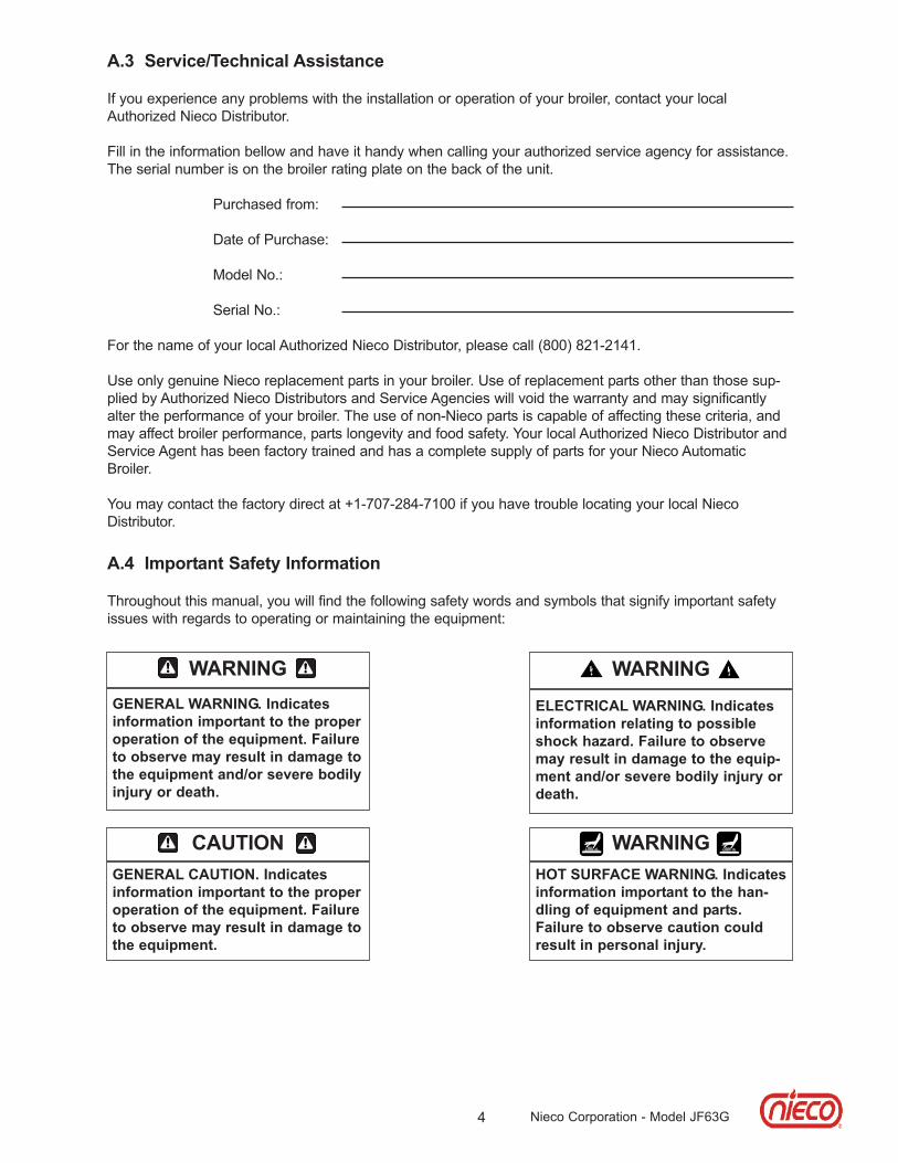
WaRnInGGeneRal WaRnInG. Indicatesinformation important to the properoperation of the equipment. failureto observe may result in damage tothe equipment and/or severe bodilyinjury or death.
WaRnInGeleCTRICal WaRnInG. Indicatesinformation relating to possibleshock hazard. failure to observemay result in damage to the equip-ment and/or severe bodily injury ordeath.
CaUTIonGeneRal CaUTIon. Indicatesinformation important to the properoperation of the equipment. failureto observe may result in damage tothe equipment.
WaRnInGHoT sURfaCe WaRnInG. Indicatesinformation important to the han-dling of equipment and parts.failure to observe caution couldresult in personal injury.
Nieco Corporation - Model JF63G

5
a.4 Important safety Information (Continued.)
In addition to the warnings and cautions in this manual, use the following guidelines for safe operation ofyour Nieco Automatic Broiler:
• Read and follow all instructions before using this equipment.• Install or locate broiler only for its intended use as described in this manual. • Do not operate this equipment if it has a damaged cord or plug, if it is not working properly or if it
has been otherwise damaged.• This equipment should only be serviced by authorized personnel. Contact your local Nieco
Distributor for adjustment or repair.• Use only genuine Nieco replacement parts for your broiler. Failure to do so will void the warranty
and may significantly alter the performance of your broiler. The use of non-Nieco parts is capable of affecting these criteria, and may affect broiler performance, parts longevity and food safety.
The following warnings and cautions appear throughout the manual and should be carefullyobserved:
• Turn the broiler off, close the main gas valve, and disconnect the plug before performing any service, maintenance or cleaning on the broiler.
• always allow the broiler to fully cool before performing any service, maintenance or cleaning. failure to wait for the broiler to cool fully may result in personal injury.
• The procedures in this manual may include reference to the use of chemical products. The nieco Corporation does not endorse the use of any particular cleaning/degreasing agent. Use only those chemicals that are approved for use in your kitchen.
• The broiler should be grounded according to local electrical codes to prevent the possibility of electrical shock. It requires a grounded receptacle with separate electrical lines, protected by fuses or circuit breakers of the proper rating.
• all electrical connections must be in accordance with local electrical codes and any other applicable codes.
• The use of adequate ventilation (as rated in this manual) with this broiler is mandatory. failure to adequately ventilate this unit and provide safe operating distances (as specified in this manual) is a fire safety hazard. follow the instructions for emergency broiler shutdown in the event of an emergency.
• no attempt should be made to operate this appliance in the event of a power failure.
WaRnInG eleCTRICal sHoCK HaZaRD. faIlURe To folloW THese InsTRUCTIons CoUlDResUlT In seRIoUs InJURY oR DeaTH:
_ electrical ground is required on this appliance._ Check with a qualified electrician if you are in doubt as to whether the appliance is properly
grounded._ Do not use water on or near the control box for risk of serious injury or death due to
electrical shock.
WaRnInG, HIGH TeMPeRaTURes WITH HoT sURfaCes. faIlURe To folloW THese PRoCe-DURes CoUlD ResUlT In seRIoUs InJURY:
_ Do not attempt to clean, disassemble or perform maintenance on this broiler until it is fully cooled as per the instructions contained in this manual.
Nieco Corporation - Model JF63G

6 Nieco Corporation - Model JF63G
b. InsTallaTIonb.1 Pre-InstallationUncrate the broiler and inspect for shipping damage. Remove the tape securing the machine parts, andinstall the parts in their proper location. If there are obvious or concealed damages to any part of thebroiler, please contact your freight carrier. The factory warranty does not cover freight damage.
b.2 MountingFollow the mounting instructions if this function is not performed by the installer.
b.3 levelingThe grease drain system is based on a gravity-flow design. Therefore, it is extremely important that thebroiler be placed on a level surface.
b.4 Hood RequirementsThis appliance must be installed under a ventilation hood of adequate size. Do not obstruct the flow ofcombustion and ventilation air. An adequate air supply must be available for safe and proper operation.
For installations in the Commonwealth of Massachusetts the following shall apply: Venting shall be incompliance with NFPA Section 10.3.5.2 for the Model JF93.
b.5 ClearanceKeep appliance area free from combustibles.
To facilitate disassembly and service of the unit a minimum of 24” (610 mm) should be allowed on thecontrol panel (feed end) of the broiler.
ReQUIReD for installation near combustible walls and construction
ReQUIReD for installa-tion near non-com-bustible walls and construction
ReCoMMenDeD byNieco for proper disas-sembly and service
Back of broiler
Sides of broiler
Front of broiler(Feed end)
ReQUIReD anD ReCoMMenDeD CleaRanCes
12” (305 mm) 0” (0 mm)
0” (0 mm)
24” (610 mm)
0” (0 mm)
0” (0 mm)
0” (0 mm)
12” (305 mm)
12” (305 mm)
7
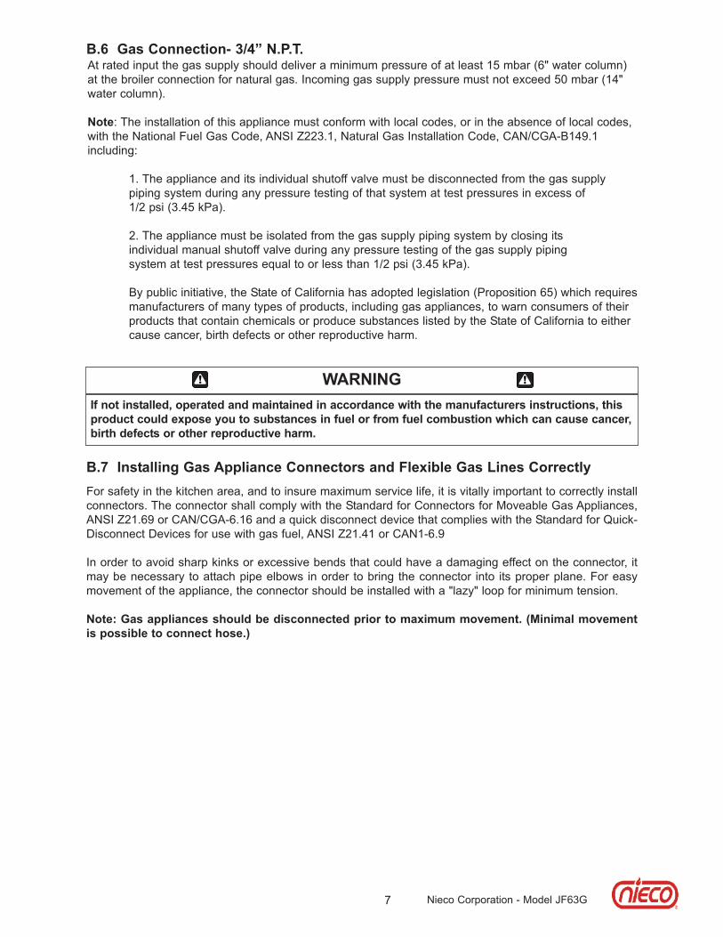
b.6 Gas Connection- 3/4” n.P.T. At rated input the gas supply should deliver a minimum pressure of at least 15 mbar (6" water column)at the broiler connection for natural gas. Incoming gas supply pressure must not exceed 50 mbar (14"water column).
note: The installation of this appliance must conform with local codes, or in the absence of local codes,with the National Fuel Gas Code, ANSI Z223.1, Natural Gas Installation Code, CAN/CGA-B149.1 including:
1. The appliance and its individual shutoff valve must be disconnected from the gas supply piping system during any pressure testing of that system at test pressures in excess of 1/2 psi (3.45 kPa).
2. The appliance must be isolated from the gas supply piping system by closing its individual manual shutoff valve during any pressure testing of the gas supply piping system at test pressures equal to or less than 1/2 psi (3.45 kPa).
By public initiative, the State of California has adopted legislation (Proposition 65) which requiresmanufacturers of many types of products, including gas appliances, to warn consumers of theirproducts that contain chemicals or produce substances listed by the State of California to eithercause cancer, birth defects or other reproductive harm.
Nieco Corporation - Model JF63G
For safety in the kitchen area, and to insure maximum service life, it is vitally important to correctly installconnectors. The connector shall comply with the Standard for Connectors for Moveable Gas Appliances,ANSI Z21.69 or CAN/CGA-6.16 and a quick disconnect device that complies with the Standard for Quick-Disconnect Devices for use with gas fuel, ANSI Z21.41 or CAN1-6.9
In order to avoid sharp kinks or excessive bends that could have a damaging effect on the connector, itmay be necessary to attach pipe elbows in order to bring the connector into its proper plane. For easymovement of the appliance, the connector should be installed with a "lazy" loop for minimum tension.
note: Gas appliances should be disconnected prior to maximum movement. (Minimal movementis possible to connect hose.)
b.7 Installing Gas appliance Connectors and flexible Gas lines Correctly
WaRnInGIf not installed, operated and maintained in accordance with the manufacturers instructions, thisproduct could expose you to substances in fuel or from fuel combustion which can cause cancer,birth defects or other reproductive harm.

8 Nieco Corporation - Model JF63G
b.9 electrical Connection Power requirements are stated on the unit nameplate and must be connected accordingly. This appli-ance, when installed must be electrically grounded in accordance with local codes, or in the absence oflocal codes, with the National Electrical Code, ANSI/NFPA 70, or the Canadian Electrical Code, CSAC22.2, as applicable. Before starting broiler, tighten all electrical connections in control box. An electricalwiring diagram can be found inside the control box.
note: Disconnect power before servicing.
b.10 Pre-operation CheckBe sure that all parts are installed in the proper location:
� Ventilation is turned on� Broiler is plugged in� Gas line is connected
b.8 Restraining Device Installation and UseThis high strength restrainer is to be used with all moveable (castered) appliances. It fully complies withAmerican Gas Association requirements. References: Z21.69, Z83.11, and Z21.41 with current revisions.Installation is quick and positive. In Canada, device is in accordance with CAN 1-6.9-M70 QuickDisconnect Devices for use with gas fuel, and CAN 1-6.10-88 metal connectors for gas appliances.Correct length for any appliance is simply a matter of loosening two adjuster clips (1) and re-tightening.(3" to 6" shorter than appliance connector is desired length.) Restrainer is made of heavy duty steelcable, with a strong scissor hood (2) at one end, and an equally strong spring hook (3) at the other.Cotter pin (4) is supplied to secure the installation. For proper attachment to the broiler, use the suppliedhardware to attach the device to the holes in the shear plate of the broiler stand. noTe: If disconnection of the restraint is necessary, reconnect the restraint after the appliancehas been returned to its originally installed position.

9 Nieco Corporation - Model JF63G
C. oPeRaTIon
C.1 Controls and IndicatorslefT sIDe
1. Belt Speed Control (P/N 13727-B) - Used to set the broil time on the meat belt.
2. Temperature Control (P/N 19076) - Helps keep the broiler temperature stable when the broiler is under heavy load.
1
2
on THe baCK of THe bRoIleR
1. Belt reverse buttons. Pres and hold these buttons to reverse the direction of the belt to help free a belt jam.
2. Shaft cleaning tool. Use this tool on the drive and idler shafts to scrape them clean.
1
2
1
RIGHT sIDe
3. Main Power Switch..
4.. Power Indicator Light.5. Ignition Failure Light.
4
35

10
C.2 lighting Procedures
1. Broiler is centered under hood and plugged in
2. Gas valve is open when handle is in line (parallel to) the pipe
3. Turn ventilation system on
The JF63G is equipped with automatic ignition. When the broiler is turned on, a hot surface ignitor turns on 5 secondsbefore the flow of gas. Gas then flows to all of the burners. If the burners are not lit within 10 seconds, the control willreset and try again for 10 seconds. This occurs 3 times. If the broiler does not light after the third attempt, the ignitionfailure light will flash and the main on/off switch must be cycled to repeat the procedure. If this still doesn’t light thebroiler, see the MANUAL IGNITION instructions.
WaRnInGTHe VenTIlaTIon sYsTeM MUsTbe on aT all TIMes DURInGbRoIleR oPeRaTIon. oPeRaT-InG bRoIleR WITHoUT PRoPeR VenTIlaTIon Is a seVeRe fIReHaZaRD.
noRMal IGnITIon
PRe-lIGHTInG PRePaRaTIon
Nieco Corporation - Model JF63G
1. Turn the MaIn PoWeR sWITCH on. 1.
2.2. Allow broiler to heat for 45 minutes before cooking.

11
C.2 lighting Procedures (Continued.)
ManUal IGnITIon
Nieco Corporation - Model JF63G
1. Allow the broiler to run free of any product for 10 minutes.This will burn the chain clean.
2. Close the maingas valve and allow the broiler to run without gas for 10 minutes.
3. Turn off the Main Power switch.
4. Wait for the broiler to cool.
C.3 shutdown Procedures
PlanneD sHUTDoWn
2. Close the MaIn Gas ValVe
Valve is closedwhen it is perpendi-cular to pipe.
eMeRGenCY sHUTDoWn1. Turn off the
MaIn PoWeR sWITCH.
Your Nieco Automatic Broiler is designed to automatically stop gas flow to the broiler in the event of power failure, gaspressure loss or any other related incident. No attempt to operate this appliance should be made in the event of a powerfailure.
CaUTIonIn a prominent location, postinstructions to be followed in theevent the user smells gas. Thisinformation shall be obtained byconsulting your local gas supplier.
CaUTIon
foR YoUR safeTY: Do not storeor use gasoline or other flammablevapors or liquids in the vicinity ofthis or any other appliance.
CaUTIon
foR YoUR safeTY: In the event ofa prolonged power failure, noattempt should be made to operatethis appliance.
1. Remove the return slide. Turn the MaIn PoWeRsWITCH on. Hold a lighter/match to the first upper burneron the discharge end until the burner lights. Once the firstburner is lit, verify that all burners have ignited.
12 Nieco Corporation - Model JF93G
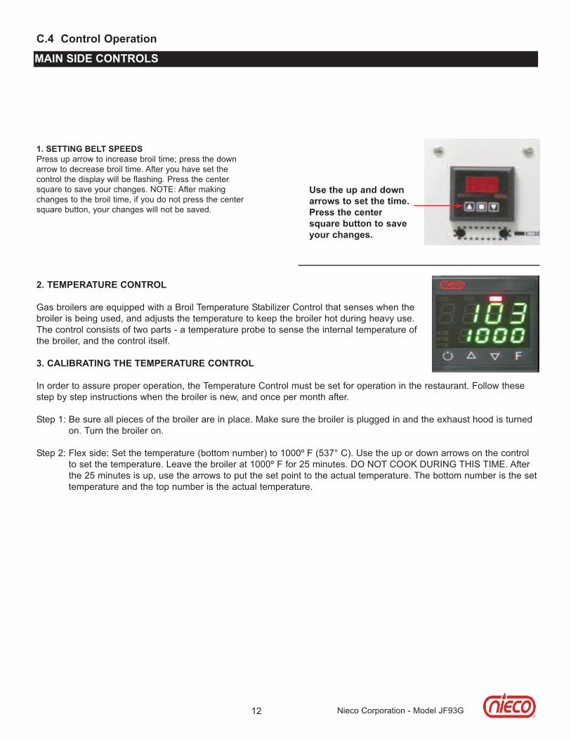
2. TeMPeRaTURe ConTRol
Gas broilers are equipped with a Broil Temperature Stabilizer Control that senses when thebroiler is being used, and adjusts the temperature to keep the broiler hot during heavy use.The control consists of two parts - a temperature probe to sense the internal temperature ofthe broiler, and the control itself.
3. CalIbRaTInG THe TeMPeRaTURe ConTRol
In order to assure proper operation, the Temperature Control must be set for operation in the restaurant. Follow thesestep by step instructions when the broiler is new, and once per month after.
Step 1: Be sure all pieces of the broiler are in place. Make sure the broiler is plugged in and the exhaust hood is turnedon. Turn the broiler on.
Step 2: Flex side: Set the temperature (bottom number) to 1000º F (537° C). Use the up or down arrows on the controlto set the temperature. Leave the broiler at 1000º F for 25 minutes. DO NOT COOK DURING THIS TIME. Afterthe 25 minutes is up, use the arrows to put the set point to the actual temperature. The bottom number is the settemperature and the top number is the actual temperature.
C.4 Control operation
MaIn sIDe ConTRols
1. seTTInG belT sPeeDsPress up arrow to increase broil time; press the downarrow to decrease broil time. After you have set thecontrol the display will be flashing. Press the centersquare to save your changes. NOTE: After makingchanges to the broil time, if you do not press the centersquare button, your changes will not be saved.
Use the up and downarrows to set the time.Press the centersquare button to saveyour changes.

13
D. CleanInG anD DIsasseMblYTurn broiler off and close the main gas valve. Disconnect the power supply to the broiler before cleaning orservicing. If this broiler is connected using a restraint, and disconnection of the restraint is necessary for clean-ing or moving the broiler, the restraint must be reconnected after the broiler has been returned to its originallyinstalled position. allow to cool for 30 minutes prior to cleaning/disassembly. leave the ventilation system onduring cooling. Use only approved cleaning, degreasing and sanitizing solutions.
all PaRTs aRe CleaneD on a DaIlY basIs Unless oTHeRWIse noTeD
follow the steps for proper disassembly. Reverse the order for reassembly.
CaUTIon
follow the Disassembly andReassembly steps to ensure properoperation of the broiler. failure todo so may result in operationalproblems.
WaRnInGbRoIleR PaRTs aRe HoT. DonoT aTTeMPT To DIsasseMbleTHe bRoIleR UnTIl IT Is fUllYCool. faIlURe To folloW THIsInsTRUCTIon MaY ResUlT InseVeRe InJURY.
WaRnInG
leaVe THe VenTIlaTIon HooDon DURInG CoolInG. faIlUReTo Do so CoUlD Pose a fIResafeTY HaZaRD.
Nieco Corporation - Model JF63G
How to read the cleaning section
The location of the part.
Pull each meat guide out slightly from the bottom,then lift off.
W ash, rinse, and sanitize in the 3-compartmentsink.
Meat Guides
Feed End
Tools
Instructions
3-Compartment Sink
Clean: Every 4 hours
1.
2.
Scrub Pad
When to clean the part.
Picture of the part to beremoved and cleaned.
How to remove andclean the parts.
The tools neededto clean the part
The name of the part to be

14 Nieco Corporation - Model JF63G
Instructions
1. Allow the broiler to run free of product for 10minutes before turning it off. This allows anyresidue to burn off the chains.Shut the broiler off and let it cool for 30minutes before disassembly and cleaning.Close the main gas valve and unplug thebroiler before cleaning.Always leave the ventilation hood on during the30 minute cool down period.Use only approved cleaning solutions.Allow parts to air dry after cleaning.
Cleaning the Broiler
3-Compartment Sink
No-Scratch Pad Scrub Pad Towel
HeatResistantGloves
Degreaser
Soft BristleBrush
Small OrificeBrush Shaft Cleaning
Tool
Tools Needed
1.
2.
This “Stop” sign shows a step in the procedurethat must be followed exactly or personalsafety could be affected.This warning symbol shows a step in theprocedure that must be followed exactly orbroiler performance could be affected.This “puzzle” symbol shows a step in thereassembly procedure that must be followed.
3.
4.
5.
!
Important SymbolsSTOP 6.
Large OrificeBrush
1. Lift the meat guides up and off the feeder.2. Wash, rinse, and sanitize in the 3-compartmentsink.
Meat Guides
Feed EndTools
Instructions
3-Compartment Sink
Clean: Every 4 hours
Scrub Pad

15 Nieco Corporation - Model JF63G
1. Slide the feeder cover towards you until itcomes off.2. Wash, rinse, and sanitize in the 3-compartmentsink.
Feeder Cover
Feed EndTools
Instructions
3-Compartment Sink
Clean: Every 4 hours
Scrub Pad
1. Pull the release pin.2. Lift push bar feeder bases up and off.3. Wash, rinse, and sanitize in the 3-compartmentsink.DO NOT lift the feeder base by the feeder bar orthe chains. This will damage the feeder base.REASSEMBLY: Pull the release pin and placefeeder base in position.
Push Bar Feeder Base (2)
Feed EndTools
Instructions
3-Compartment Sink
Clean: Every 4 hours
!
Scrub Pad

16 Nieco Corporation - Model JF63G
1. Pull the release pin.2. Lift wire belt feeder base up and off.3. Wash, rinse, and sanitize in the 3-compartmentsink.DO NOT lift the feeder base by the wire belt. Thiswill damage the feeder base.REASSEMBLY: Pull the release pin and placefeeder base in position.
Wire Belt Feeder Base (If equipped)
Feed EndTools
Instructions
3-Compartment Sink
Clean: Every 4 hours
!
Scrub Pad
1. Lift and remove.2. Wash, rinse, and sanitize in the 3-compartmentsink.REASSEMBLY: Hang feeder housing on brackets.
Feeder Housing
Feed EndTools
Instructions
3-Compartment Sink
Clean: Daily
Scrub Pad
17 Nieco Corporation - Model JF63G
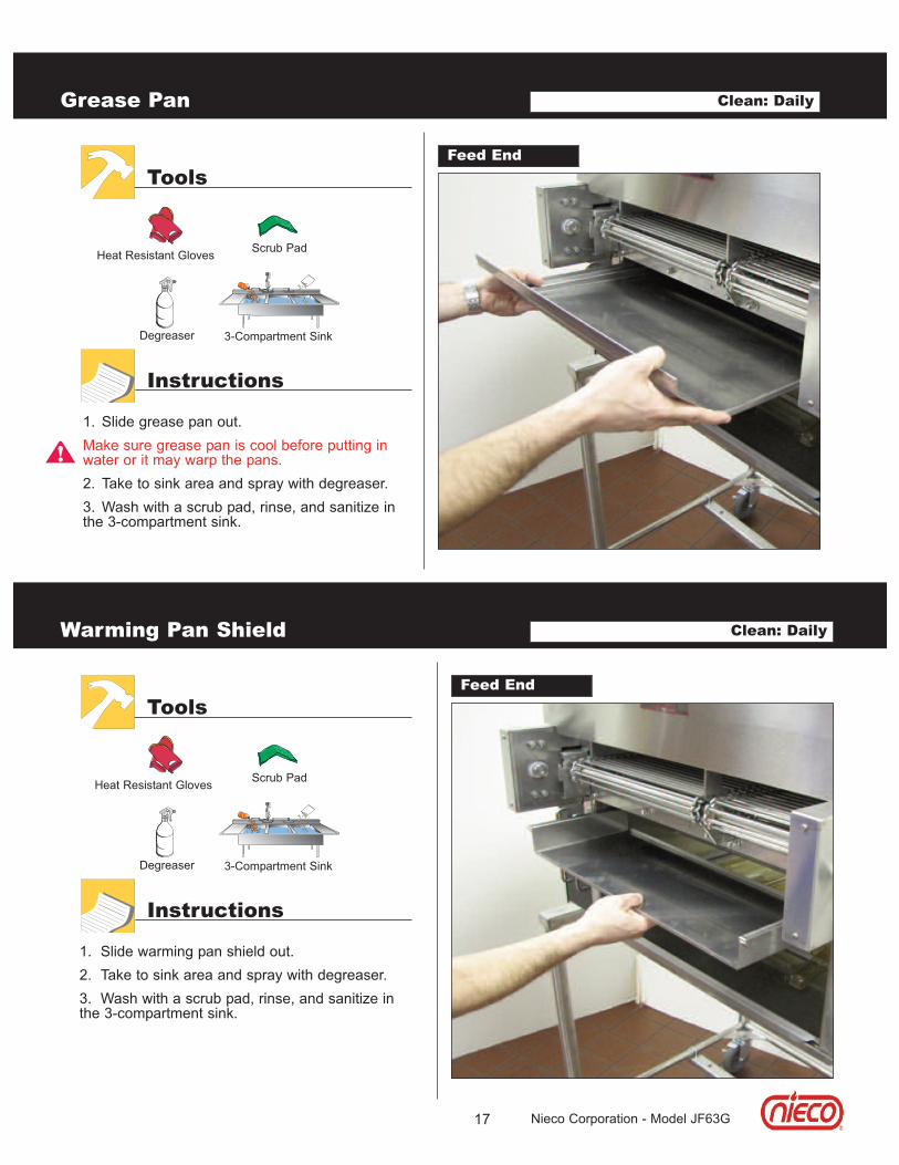
1. Slide grease pan out.Make sure grease pan is cool before putting inwater or it may warp the pans.2. Take to sink area and spray with degreaser. 3. Wash with a scrub pad, rinse, and sanitize inthe 3-compartment sink.
Grease Pan
Feed EndTools
Instructions
Clean: Daily
3-Compartment Sink
Scrub PadHeat Resistant Gloves
Degreaser
!
1. Slide warming pan shield out.2. Take to sink area and spray with degreaser. 3. Wash with a scrub pad, rinse, and sanitize inthe 3-compartment sink.
Warming Pan Shield
Feed EndTools
Instructions
Clean: Daily
3-Compartment Sink
Scrub PadHeat Resistant Gloves
Degreaser

18 Nieco Corporation - Model JF63G
1. Lift and slide bracket out.2. Take to sink area and spray with degreaser. 3. Wash with a scrub pad, rinse, and sanitize inthe 3-compartment sink.
Holding Pan Bracket
Feed EndTools
Instructions
Clean: Daily
3-Compartment Sink
Scrub PadHeat Resistant Gloves
Degreaser
1. Slide crumb tray out.2. Take to sink area and spray with degreaser. 3. Wash with a scrub pad, rinse, and sanitize inthe 3-compartment sink.
Crumb Tray
Feed EndTools
Instructions
Clean: Daily
3-Compartment Sink
Scrub PadHeat Resistant Gloves
Degreaser

19 Nieco Corporation - Model JF63G
1. Clean product holding area while still warm.2. Wring out a soapy towel and wash productholding area.3. Wring out a sanitized towel and wipe product holding area.
Product Holding Area
Feed EndTools
Instructions
Soapy Towel
Clean: Daily
Sanitized Towel
1. Lift up and off.2. Take to sink area and spray with degreaser. 3. Wash, rinse, and sanitize in the 3-compartmentsink.
Discharge Heat Shield
Discharge EndTools
Instructions
Clean: Daily
3-Compartment Sink
Scrub PadHeat Resistant Gloves
Degreaser
20 Nieco Corporation - Model JF63G
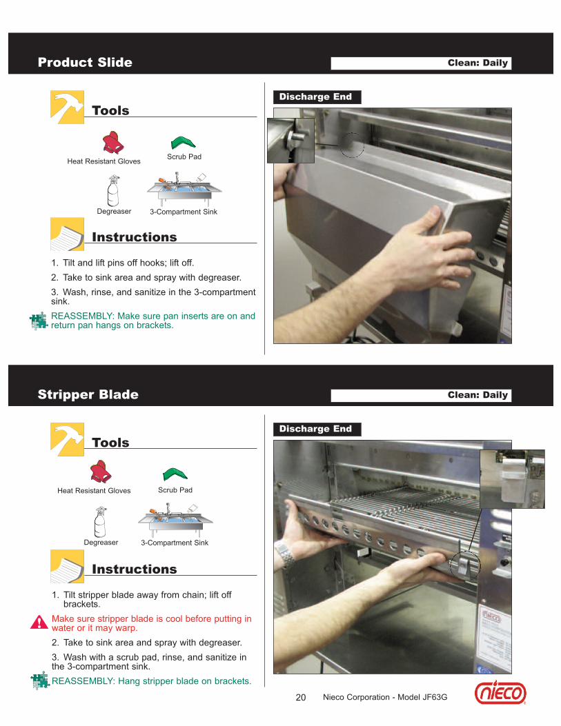
1. Tilt and lift pins off hooks; lift off.2. Take to sink area and spray with degreaser. 3. Wash, rinse, and sanitize in the 3-compartmentsink.REASSEMBLY: Make sure pan inserts are on andreturn pan hangs on brackets.
Product Slide
Discharge EndTools
Instructions
Clean: Daily
3-Compartment Sink
Scrub PadHeat Resistant Gloves
Degreaser
1. Tilt stripper blade away from chain; lift off brackets.
Make sure stripper blade is cool before putting inwater or it may warp.2. Take to sink area and spray with degreaser.3. Wash with a scrub pad, rinse, and sanitize inthe 3-compartment sink. REASSEMBLY: Hang stripper blade on brackets.
Stripper Blade
Discharge EndTools
Instructions
Clean: Daily
3-Compartment Sink
Scrub PadHeat Resistant Gloves
Degreaser
!
21 Nieco Corporation - Model JF63G
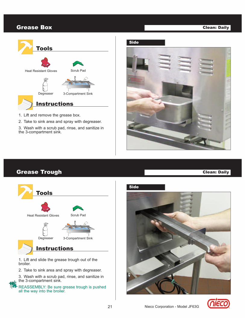
1. Lift and remove the grease box.2. Take to sink area and spray with degreaser.3. Wash with a scrub pad, rinse, and sanitize inthe 3-compartment sink.
Grease Box
SideTools
Instructions
Clean: Daily
3-Compartment Sink
Scrub PadHeat Resistant Gloves
Degreaser
1. Lift and slide the grease trough out of thebroiler.2. Take to sink area and spray with degreaser.3. Wash with a scrub pad, rinse, and sanitize inthe 3-compartment sink. REASSEMBLY: Be sure grease trough is pushedall the way into the broiler.
Grease Trough
SideTools
Instructions
Clean: Daily
3-Compartment Sink
Scrub PadHeat Resistant Gloves
Degreaser

22 Nieco Corporation - Model JF63G
3-Compartment Sink
1. Lift the burner latch.2. Slide burner out.3. Take to the 3-compartment sink and scrub witha scrub pad or nylon brush.4. If necessary, use a stiff toothbrush to clean anyclogged burner holes.REASSEMBLY: Be sure the holes on the burnerare facing up.Burner must be completely dry beforereassembly. Dry with a paper towel.
Lower Burner
SideTools
Instructions
Clean: Daily
Heat Resistant GlovesScrub Pad
!
EXTREMELY HOT! Be careful not to burn yourself. 1. Grasp handle and lift Incendalyst™ off toremove from chimney.2. SOAK IN WARM WATER FOR 1 HOUR. RINSEWITH WATER ONLY. NEVER USE ANYCHEMICALS ON THE CATALYST.3. Lay flat to drain water and let air dry overnight.4. Make sure Incendalyst™ is dry before puttingback on broiler.
Incendalyst™
TopTools
Instructions
Heat Resistant Gloves
Clean: Daily
CAUTION: Extremely Hot

23 Nieco Corporation - Model JF63G
EXTREMELY HOT! Be careful not to burnyourself. 1. Lift Incendalyst™ chimney up and off.2. Take to sink area and spray with degreaser.3. Wash with a scrub pad, rinse, and sanitize inthe 3-compartment sink.
Incendalyst™ Chimney
TopTools
Instructions
Clean: Daily
3-Compartment Sink
Scrub PadHeat Resistant Gloves
Degreaser
CAUTION: Extremely Hot
EXTREMELY HOT! Be careful not to burnyourself. 1. Lift upper heat shield up and off.2. Take to sink area and spray with degreaser.3. Wash with a scrub pad, rinse, and sanitize inthe 3-compartment sink.
Upper Heat Shield
TopTools
Instructions
Clean: Daily
3-Compartment Sink
Scrub PadHeat Resistant Gloves
Degreaser
CAUTION: Extremely Hot
FRONT
ReasseMblY: be sure that thearrows on the Upper Heat shieldpoint towards the rear of broiler.
24 Nieco Corporation - Model JF63G
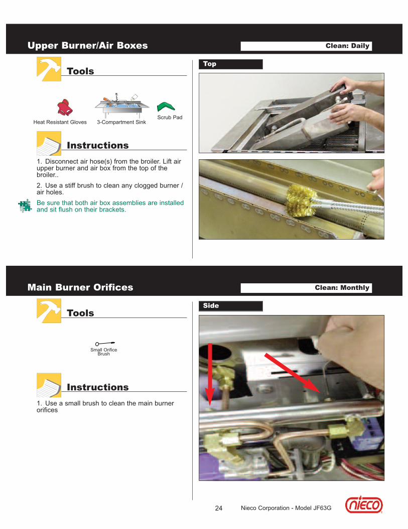
1. Disconnect air hose(s) from the broiler. Lift airupper burner and air box from the top of thebroiler..2. Use a stiff brush to clean any clogged burner /air holes.Be sure that both air box assemblies are installedand sit flush on their brackets.
Upper Burner/Air Boxes
TopTools
Instructions
Clean: Daily
3-Compartment SinkScrub Pad
Heat Resistant Gloves
1. Use a small brush to clean the main burnerorifices
Main Burner Orifices
SideTools
Instructions
Clean: Monthly
Small OrificeBrush
25 Nieco Corporation - Model JF63G
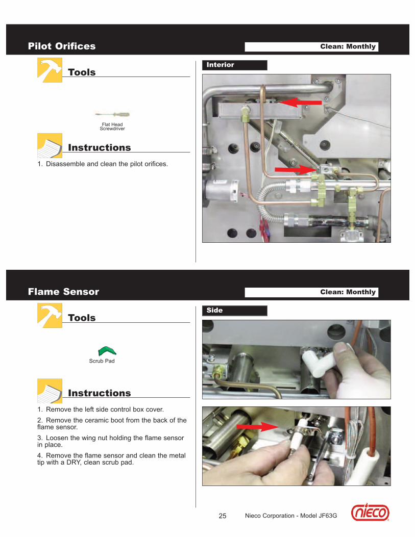
1. Disassemble and clean the pilot orifices.
Pilot Orifices
InteriorTools
Instructions
Clean: Monthly
Flat HeadScrewdriver
1. Remove the left side control box cover.2. Remove the ceramic boot from the back of theflame sensor.3. Loosen the wing nut holding the flame sensorin place.4. Remove the flame sensor and clean the metaltip with a DRY, clean scrub pad.
Flame Sensor
SideTools
Instructions
Clean: Monthly
Scrub Pad
26 Nieco Corporation - Model JF63G
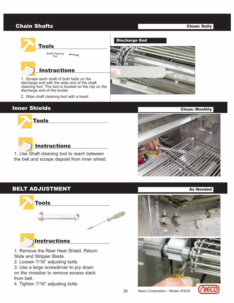
1. Scrape each shaft of both belts on thedischarge end with the wide end of the shaftcleaning tool. The tool is located on the clip on thedischarge end of the broiler.2. Wipe shaft cleaning tool with a towel.
Chain Shafts
Discharge EndTools
Instructions
Clean: Daily
Shaft CleaningTool
BELT ADJUSTMENT As Needed
Tools
Instructions
1. Remove the Rear Heat Shield, ReturnSlide and Stripper Blade.2. Loosen 7/16” adjusting bolts.3. Use a large screwdriver to pry downon the crossbar to remove excess slackfrom belt.4. Tighten 7/16” adjusting bolts.
Inner Shields
Tools
Instructions1. Use Shaft cleaning tool to reach betweenthe belt and scrape deposit from inner shield.
Clean: Monthly

e. TRoUblesHooTInG
27
always verify that the broiler is properly assembled, the hood is on, gas valve open and broiler is plugged in.
Nieco Corporation - Model JF63G
No power to broiler when the switch is turned on.
Broiler has power, but the burners do not light.
Red light blinking on left control box.
Hot surface ignitor does not heat.
Power is on, broiler is lit, but the conveyor belts are notturning.
Feeder belt not moving.
Feeder jams.
Burgers sticking to slide or stripper blade.
CooKInG PRobleMsBurgers under or over cooked.
Excessive flaming in broiler.
Check: Broiler is plugged in.Ventilation hood is on.Circuit Breaker on wall panel is on.
Check: Ventilation hood is on.Gas line is properly plugged in.Manual gas valve (if equipped) is on.Burners are installed properly.Burners are clean and dry.Flame sensor wire connection.
Follow manual lighting instructions.
Check the items above for burners not lighting.Turn power off and on again to reset ignition.Follow manual lighting instructions.
Check for loose wires connecting the hot surface igni-tor.Follow manual lighting instructions.
Check for a jam in the conveyor belt. Check the stripperblade and the flame arrestors to make sure they areinstalled properly.
Make sure the feeder is assembled properly.Check for jam.Make sure the drive pin is engaged.
Make sure the burgers are not frozen together.
Clean the slide and stripper blade very thoroughly. Check cookout temperature (undercooking).
Adjust conveyor belt speed.Clean burners and orifices.
Clean the catalyst if equipped.Check the hood for proper operation.Check product for overcooking.

28 Nieco Corporation - Model JF63G
f. PaRTs loCaTIon DRaWInGs
P/N
253
35
P/N
228
40
P/N
241
93
HO
OD
AIR
BO
X ,
FRO
NT
RE
TUR
N S
LID
E
AIR
BO
X, R
EA
R
HO
TEL
PAN
SLU
DG
E T
RAY
HE
AT R
EFL
EC
TOR
, UP
PE
R
HE
AT S
HIE
LD R
EA
R
STR
IPP
ER
BLA
DE
LOW
ER
BU
RN
ER
P/N
228
98
P/N
233
36
P/N
254
89
P/N
212
04
P/N
212
02
P/N
219
92

29 Nieco Corporation - Model JF63G
f. PaRTs loCaTIon DRaWInGsP
/N 2
1201
P/N
226
34
GR
EA
SE
PA
N, S
LOP
ED
HE
AT S
HIE
LD, F
RO
NT
FEE
DE
R C
OV
ER
HE
AT S
HIE
LD, H
OLD
ING
PA
N
EN
CLO
SU
RE
, DU
AL
BE
LT
P/N
242
11
P/N
221
56
P/N
219
98
30 Nieco Corporation - Model JF63G
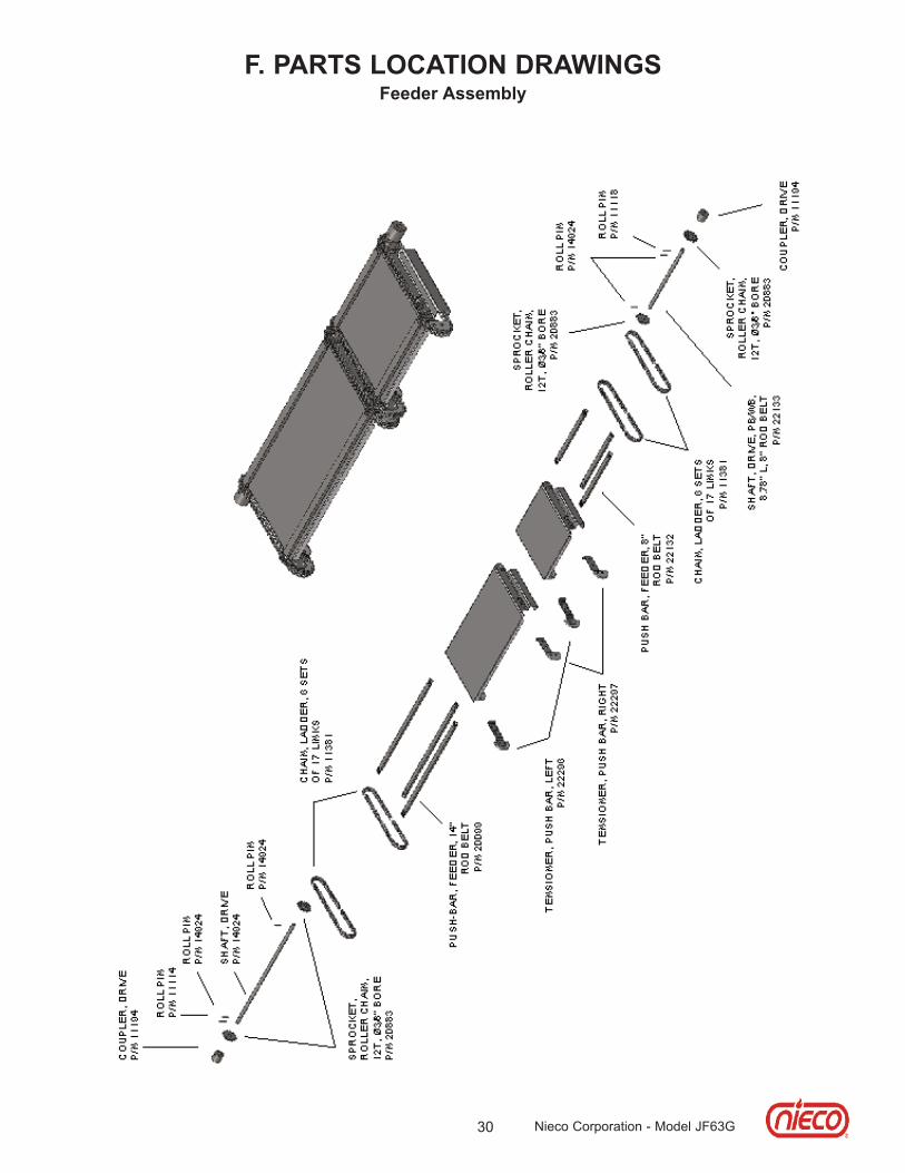
f. PaRTs loCaTIon DRaWInGsfeeder assembly

31 Nieco Corporation - Model JF63G
f. PaRTs loCaTIon DRaWInGsClutch assembly
BE
AR
ING
, S
HO
UL
DE
R
WA
SH
ER
, L
AR
GE
,
FE
ED
ER
DR
IVE
P/N
14
89
6
SP
RO
CK
ET
, C
LU
TC
HE
D,
13
T,
BE
LL
EV
ILL
E S
PR
ING
P/N
14
90
0

32 Nieco Corporation - Model JF63G
G. PaRTs RePlaCeMenT lIsT
PaRT no DesCRIPTIon
aIR boX CoMPonenTs20909 CONNECTOR, FLEX, ؾ" X 16" - ASSY25335 HEAT REFLECTOR, UPPER20903 RESTRICTOR, AIR BLOWER, 1/4" BORE,JF25489 AIR BOX, FRONT, 21.38", JF - WLDMT24193 AIR BOX/BURNER, REAR, 21.38", JF - WLDMT19764 HEATER HOSE, ¾ ID X 2"18447 BLOWER, HIGH PRESSURE, 24VDC, 2 WIRE20705 BURNER, DOUBLE FULL, Ø1" X 26.19" - WLDMT
Gas bURneR CoMPonenTs18152 ORIFICE, 1/8-27, FLAT TIP, #52 NAT2182 ORIFICE, PILOT (3225) NAT2047 ORIFICE, PILOT TOWN GAS(5232) NAT2022 ORIFICE, BURNER, #44 NAT22930 ZIP TUBE PILOT ORIFICE #70 NAT20826 ZIP TUBE, 8.44" LONG, JF - WLDMT18160 ORIFICE, 1/8-27, FLAT TIP, #60 LP17276 ORIFICE, PILOT, (4214) LP23481 ORIFICE, ZIP TUBE, #78 LP2065 ORIFICE, BURNER, #54 LP2049-A1 SPRING, RV48, 5 - 12", LP2023 ORIFICE, PILOT, UPPER (4212) LP2179 PILOT BURNER (LOWER)2180 PILOT BURNER (UPPER)17185 SENSOR, FLAME, SLOTTED18861 THERMOCOUPLE PROBE 1.88 TYPE J 48" LEADS10291 IGNITOR HOT SURFACE, 24V2049-A REGULATOR 3/412741 SOLENOID VALVE 24 VAC, 1/4 COMP. FITTING19054 SOLENOID VALVE, 1/2 NPT, 24 VAC21316 VALVE MODULATING, 24V,1/2

33 Nieco Corporation - Model JF63G
G. PaRTs RePlaCeMenT lIsT
belT DRIVe sYsTeM & beaRInGs6027 #35 DRIVE CHAIN6048 MASTER LINK Assy6047 TEFLON BEARING, DRIVE SHAFT6049 TEFLON BEARING, IDLER20786 GEAR MOTOR, DC, BRUSHLESS, REVERSE SHAFT
17899 SPROCKET, DRIVE MOTOR11081 IDLER SPROCKET20786 GEAR MOTOR, DC, BRUSHLESS, REVERSE SHAFT
20774 BEARING, ALUM/BRZ, Ø5/8" SHAFT X 1.19" WIDE17899 SPROCKET, DRIVE MOTOR11081 IDLER SPROCKET6049 TEFLON BEARING, IDLER6048 MASTER LINK Assy6047 TEFLON BEARING, DRIVE SHAFT, 3/4" SHAFT6046 TEFLON BEARING, DRIVE SHAFT, 1 1/4" SHAFT6027 #35 DRIVE CHAIN
eleCTRICal eleMenTs & ConTRols22959 ELEMENT - 25.68", 750W, 120V, Ø.4319076 CONROL,MODULATING VALVE,24V16921 CONTROL, IGNITION, 24V17201 LIGHT, IGNITION LOCK-OUT, LED4402 GREEN INDICATOR LIGHT13727-B MOTOR CONTROL 13579 SWITCH, MOTOR REVERSING22929 TRANSFORMER, 100-115-230VAC x 18-24VAC16034 CONTROL TRANSFORMER15480 MAIN ON/OFF SWITCH12725 BRIDGE RECTIFIER17173 RAIL, POWER CONNECTION, 1ø, 10MM - ASSY

G. PaRTs RePlaCeMenT lIsT
sHeeT MeTal PaRTs22840 HOOD, CHIMNEY, 23"22633 GREASE PAN21204 TRAY, SLUDGE, GREASE21230 TRAY, GREASE DRIP22898 GREASE BOX 4" DEEP21202 HEAT SHIELD, REAR21201 HEAT SHIELD, FEEDER22634 HEAT SHIELD, HOLDING PAN,23336 SLIDE, SHORT, 23" FRAME,22156 COVER, MULTI FEEDER, 23" FRAME22135 STRIPPER BLADE 14" and 8" belt21992 STRIPPER BLADE, FIXED, 12" & 10" BELT, JF22007 FRAME, 1/2" TO 1" PATTY, 8" BELT - ASSY22003 FRAME, 1/2" TO 1" PATTY, 14" BELT - ASSY22162 FRAME, 1/2" TO 1" PATTY - 10" BELT - ASSY22119 FRAME, 1/2" TO 1" PATTY, 12" BELT, JF - ASSY
DUal belT feeDeR11608 Black Knob - Clutch Assembly15882 Complete Clutch Assembly (1 for each Feeder Assy.)20884 DRIVE ASSY W/CLUTCH,21998 ENCLOSURE22129 DRIVE UNIT, PUSH BAR, 14"22134 DRIVE UNIT, PUSH BAR, 8"22137 DRIVE UNIT, WB, 8" BELT, JF, RIGHT - ASSY22144 DRIVE UNIT, WB, 14" BELT, JF, LEFT - ASSY21984 DRIVE UNIT, PB, 10" BELT, RH, 23" FRAME - ASSY21288 DRIVE UNIT, PB, 12'' BELT, LH, 23" FRAME - ASSY22128 DRIVE UNIT, WB, 12" BELT, JF, LEFT - ASSY21984 DRIVE UNIT, PB, 10" BELT, RH, 23" FRAME - ASSY22009 DRIVE UNIT, WB, 10" BELT, JF, RIGHT - ASSY22156 COVER,FEEDER22297 TENSIONER ASSY. PTFE, LEFT22296 TENSIONER ASSY. PTFE, RIGHT22132 PUSH BAR,FEEDER, 8"11381 CHAIN, LADDER, 13 GA20099 PUSH BAR,FEEDER, 14"6121 ROD BELT, 7 GA, 5/8" PITCH, 8" WIDE6036 ROD BELT, 7 GA., 5/8" PITCH, 14" WIDE6123 ROD BELT, 7 GA., 5/8" PITCH, 12" WIDE6034 ROD BELT, 7 GA., 5/8" PITCH, 10" WIDE
MIsCellaneoUs20860 INCENDALYST, 15.19" X 16" X 1.5", 29 CPI23307 CLEANING BRUSH, JF23265 TOOL, COMBO CLEANING23433 SHIM, LEVELING, 12 GA, BROILER STAND
34 Nieco Corporation - Model JF63G

35 Nieco Corporation - Model JF63G
H. WIRInG DIaGRaMs115V Wiring
12
4 653217 8 9 10 11
PRISECTr
ansf
orme
r P/
N 22
929
Remo
te LED
P/N
1720
1
+
-~
~
notc
hBridge
Rec
tifier
P/N
1272
5
Main Power
Switch
P/N
1548
0
High Pressure BlowerP/N 18447
B #12
W #12
W
B
B
WRR
Tan #18 TGGT
Tan #18 TGGT
GPur
G
Pur
R
B
B
Pur
Pur Br
RB
To Multi Pro
duct
Contr
olWG
W
Moto
r Ca
ble
M otor Reverse SwitchP/N 13579
R
B
B
24VDC +
24VDC -
24VAC
24VAC
B
B
R-Bl
To Ignition
Module
21
2223
33
28
26
25
24
3635
12
3
14
13
12
986
5
4
20
1918
16 15
17
B #12
W #1212
34
W
B
5
67
7B
Pur
G98
B
W10W
12
13
14
RB
B
G19
Pur17
G
18
G
16
20 B
21
B
B
22
R
25
R 26
R29
R30
B24
33
34
35 36
RB
Motor
P/N
2078
6Ca
ble
P/N
1816
8
F1F2
Fuseholders (2)P/N 4405-31
Fuse F1 .25A P/N 4621-0025F2 2A P/N 4621-02
Warm
ing Elem
ent 2
30V
JF92
P/N x
xxxx
JF93
P/N 2
2509
JF94
P/N x
xxxx
Gree
n Light
P/N
4402
115V
Ver
sion
Ground Block
Right Side
Contr
ol B
ox
Powe
r Co
rd not s
upplie
d
Term
inal B
lock
(2)
P/N
4405-1
6Gr
ound B
lock
P/N
4405-1
8
6162
Tran
sfor
mer
P/N160
34
Note
: For
115
oper
ation
The
blue
and bro
wn
wire
s ar
e not us
ed.
Conduit to lef
t co
ntro
l box
28R-
Bl29
30
B-W
2315
Br B R
6162
6665
Ther
moco
uple
P/N
1886
1
R-WW
To Tem
pera
ture
Contro
lPa
ge 1 of
2
Ground BlockP/N 18688
Terminal Blocks (3)P/N 18616
Right Side
Contr
ol B
ox
L1N
+
-~
~
notc
hBridge
Rec
tifier
P/N
1272
5
Br
Pur
70
70
71
71
Br
Pur
18VD
C24
VDC
1
23
8
76
54
Belt Spe
ed C
ontr
olP/N
1372
7-B
Sock
et B
ase
P/N
4136
Contro
l Se
ttings
:B
= 36
C = 41
0TLL
= 1:00
THH
= 7:
00DI
R L or
R
R27
27
R
G
34
REV.
DESC
RIPT
ION
DATE
BYA
Initi
al Re
leas
e3-
May
-11
PBB
Corre
cted
Mot
or P/
N; Re
vised
mod
. valv
e wiri
ng19
-May
-11
PBC
Corre
cted
Fuse
hold
er P/
N; C
orre
cted
1603
419
-May
-11
PB tr
ansfo
rmer
wiri
ng; A
dded
grou
nd to
1905
4 sol
. valv
eD
Tran
sform
er 21
642 w
as 10
529
29-M
ar-1
2KK
ETe
rmin
al bl
ock 4
405-
16 &
-18 w
ere 1
8871
& 18
873
19-Ju
n-12
KKF
Tran
sform
er 22
929 w
as 21
642
17-Se
p-12
CSG
Corre
cted
2292
9 Tra
nsfo
rmer
wiri
ng24
-Sep-
12CS
HCo
rrect
ed no
te fo
r tra
nsfo
rmer
10
-Oct
-12
CSJ
Adde
d tra
cer w
ires
15-Ju
l-13
KK
B11
B11
W10
Br Bl
B-W
19Ma
y11
JModel
Rev.
This
doc
umen
t is
the
pro
pert
y of
Nie
co
Corp
orat
ion.
Rep
ordu
ctio
n or
rel
ease
wit
hout
ex
pres
s pe
rmis
sion
is
proh
ibit
ed
Wiri
ng D
iagr
amDwg No.
Drawn
Date
PBJF
62G;
JF62-2G
; JF
63G
JF63-2
G; J
F64G;
JF64-2
G19
117

36 Nieco Corporation - Model JF63G
H. WIRInG DIaGRaMs115V Wiring
1
23
8
76
54
Belt Speed Contr
olP/N 13
727-
BSock
et B
ase
P/N 41
36
Control Se
ttings
:B = 36
C =
410
TLL =
1:00
THH =
7:00
DIR L or R
S1 S2L1 L2 W MV1
GND
LEDFC
Ignition Module
P/N 16
921
24VA
CDC
Signal+ -
Hot Surf
ace Ignitor
P/N 10
291
Motor Re
vers
e Switch
P/N 13
579
24VA
C
BlY
BrG
Br
Br
Or
W
W
G
B
RB
B
W
B
Tan
B
B
Tan
4039
3837
41
42 43
54
53
52
51
50
4948
47 46
4544
56
55
B38
41 Bl
Br40
39 Br
B
R
47 Y
46
G
4544
42
43
49
51
G
G
Or
Motor
P/N 20
786
Cable
P/N 18
168
50B
Flam
e Se
nsor
P/N 17
185
Sensor Wire
P/N 18
052
Main Gas
Solenoid Valve
P/N 19
054
Modulating Gas
Valve
P/N 21
316
Pilot Shutoff
Solenoid Valve
P/N 12
741
DIP sw
itch
es
must
be
set for
prop
er ope
rati
on.
Switch
1 and 2
on
, an
d 3
off.
1 2 3Ground Block
P/N 18
688
Left
Side
Contro
l Bo
x
Term
inal Block
s (3)
P/N 18
686
Use
.250
" Spade
Connec
tors
G/Y
57
57
1 2 3 4 5
137 8 9 10
14
6
1112
W (+)
R (-
)
B
R
3231
Temper
atur
e Co
ntrol
P/N 19
076
R
61 62B R
1523 30
29
3029
15 23B-WBr
R
28
28
3231
5455
48
67
G/Y
W
WB
R-Bl
To Rem
ote LED
On Right Contr
ol Box
6162
WR-W
6665
6665
R-W
WR RBr B-W
R-Bl
3752
53
Ther
mocouple
P/N 18
861
19MA
Y11
JMo
del
Rev.
This document is the property of Nieco
Corporation. Reproduction or release without
express permission is prohibited
Wiring Diagram
Dwg No
.Dr
awn
Date
PB19
117
Page 2 of 2
24VD
C+
24VA
C
24VD
C-
67
onof
f
LED
Butt
on #
2Low Ga
s Ad
just
ment
Butt
on #
1Hi
gh Gas
Adjus
tmen
t
Conduit
G W B R
R
B
JF62G;
JF62-2G
; JF
63G
JF63-2
G; J
F64G
; JF64-2
G

37 Nieco Corporation - Model JF63G
H. WIRInG DIaGRaMs230V Wiring
12
4 653217 8 9 10 11
PRISEC
Transf
orme
r P/
N 22
929
Remo
te LED
P/N
1720
1
+
-~
~
notc
hBridge
Rec
tifier
P/N
1272
5
Main Power
Switch
P/N
1548
0
High Pressure BlowerP/N 18447
B #12
W #12
W
B
B
W
W
RR
B Br
Bl
Tan #18 TGGT
Tan #18 TGGT
GPur
G
Pur
R
B
B
Pur
Pur Br
RB
To Multi Pro
duct
Contr
olWG
W
Motor
Cable
M otor Reverse SwitchP/N 13579
R
B
B
24VDC +
24VDC -
24VAC
24VAC
B
B
R-Bl
To Ignition
Module
21
2223
33
28
26
25
24
3635
12
3
14
13
12
11
10
986
5
4
20
1618
19 15
17
B #12
W #1212
34
W
B
5
67
7B
Pur
G98
B
W10
Bl
W
1112
13
14
RB
B
G
19
Pur
17
G
18
G
16
20 B
21
B
B
22
R
25
R
26
R29
R30
B
24
33
34
35 36
RB
Motor
P/N
2078
6Ca
ble
P/N
1816
8
F1F2
Fuseholders (2)P/N 4405-31
Fuse F1 .25A P/N 4621-0025F2 2A P/N 4621-02
Warm
ing Elem
ent 230
VJF
92 P/N x
xxxx
JF
93 P/N 2
2509
JF94
P/N x
xxxx
Gree
n Light
P/N
4402
220/23
0V Ver
sion
Ground Block
Right Side
Contr
ol B
ox
Powe
r Co
rd not s
upplie
d
Term
inal
Block
(2)
P/N
4405
-16
Ground B
lock
P/N
4405
-18
6162
Tran
sfor
mer
P/N160
34
Note:
For
230
oper
ation
The blac
k an
d br
own
wire
s ar
e co
nnec
ted.
Conduit to lef
t co
ntro
l box
28R-
Bl29
30
B-W
2315
Br B R
6162
6665
Ther
moco
uple
P/N
1886
1
R-WW
To Tem
pera
ture
Contro
lPa
ge 1 o
f 2
Ground BlockP/N 18688
Terminal Blocks (3)P/N 18616
Right Side
Contr
ol B
ox
L1N
R
+
-~
~
notc
hBridge
Rec
tifier
P/N
1272
5
Br
Pur
70
70
71
71
Br
Pur
18VD
C24
VDC
19Ma
y11
FMo
del
Rev.
This
doc
umen
t is
the
pro
pert
y of
Nie
co
Corp
orat
ion.
Rep
ordu
ctio
n or
rel
ease
wit
hout
ex
pres
s pe
rmis
sion
is
proh
ibit
ed
Wiri
ng D
iagr
amDw
g No
.Dr
awn
Date
PBJF62
G; J
F62-2G
JF63
G; J
F63-2G
1911
8
1
23
8
76
54
Belt Spe
ed C
ontr
olP/N
1372
7-B
Sock
et B
ase
P/N
4136
Contro
l Se
ttings
:B
= 36
C = 41
0TLL = 1:
00TH
H = 7:
00DI
R L or
R
R27
27
R
G
34
REV.
DESCRIPT
ION
DATE
BYA
Init
ial Re
leas
e3-
May-11
PBB
Correct
ed M
otor P/N; Re
vised 19-May-11
PBValve
wir
ing
CRe
vise b
lock
s &
remove
pwr cord
30-May-12
KKD
Correct
ed w
armin
g e
lement p
art #
7-Ju
n-1
KKE
Replace
d 15161-B w/ 13727-
B &
4136
17-Se
p-1
KKRe
move
d 1X 18447, 18093, 18092
FAd
ded t
racer w
ires
15-Ju
l-13
KK
B-W
R-W
W

38 Nieco Corporation - Model JF63G
H. WIRInG DIaGRaMs230V Wiring
1
23
8
76
54
Belt Speed Contr
olP/N 13
727-
BSock
et Bas
eP/N 41
36
Control Se
ttings
:B =
36C
= 41
0TLL = 1:
00THH
= 7:
00DIR L or
RS1 S2L1 L2 W MV1
GND
LEDFC
Ignition Module
P/N
1692
1
24VA
CDC
Signal+ -
Hot Surf
ace Ignitor
P/N 10
291
Motor Re
vers
e Switch
P/N 13
579
24VA
C
BlY
BrG
Br
Br
Or
W
W
G
B
RB
B
W
B
Tan
B
B
Tan
4039
3837
41
42 43
54
53
52
51
50
4948
47 46
4544
56
55
B38
41 Bl
Br40
39 Br
B
R
47 Y
46
G
4544
42
43
49
51
G
G
Or
Motor
P/N 20
786
Cable
P/N 18
168
50B
Flam
e Se
nsor
P/N 17
185
Sensor Wire
P/N 18
052
Main Gas
Solenoid Valve
P/N 19
054
Modulating Gas
Valve
P/N 21
316
Pilot Shutoff
Solenoid Valve
P/N 12
741
DIP switches
must
be se
t for
proper operation.
Switch 1 a
nd 2
on, and
3 off.
1 2 3Ground Block
P/N 18
688
Left
Side
Contro
l Bo
x
Term
inal Block
s (3
)P/N 18
686
Use
.250"
Spade
Connec
tors
G/Y
57
57
1 2 3 4 5
137 8 9 10
14
6
1112
W (+)
R (-)
B
R
3231
Temper
atur
e Co
ntrol
P/N 19
076
R
61 62B R
1523 30
29
3029
15 23B-WBr
B
28
28
3231
5455
48
67
G/Y
W
WB
R-Bl
To R
emote LED
On Right C
ontr
ol Box
6162
WR-W
6665
6665
R-W
WR RBr B-W
R-Bl
3752
53
Ther
mocouple
P/N 18
861
19MA
Y11
FModel
Rev.
This d
ocument is
the prope
rty of Nie
co
Corp
oration.
Reproduct
ion or rel
ease witho
ut
express pe
rmission i
s prohibit
ed
Wiring Diagram
Dwg No.
Drawn
Date
PB19
118
Page 2 o
f 2
24VD
C+
24VA
C
24VD
C-
67
onoff
LED
Button #
2Low Gas Adjust
ment
Button #
1High Gas
Adjustm
ent
Conduit
JF62
G; J
F62-
2GJF
63G; J
F63-
2G
R B

39
CaUTIon
all electrical connections must bein accordance with local electricalcodes and any other applicablecodes.
CaUTIon
Do not operate the broiler at gaspressures other than those statedhere. Doing so will affect the opera-tion of your broiler.
Nieco Corporation - Model JF63G
I. sPeCIfICaTIons
AUTOMATIC BROILERModel JF63
DIMENSIONS INCH MMLength 39.03 991Height 27.14 689Width 34.73 882
ENERGYGas connection 3/4” N.P.T.Electrical connection (specify exact voltage)
115V 1A or 220V 1A
Natural/LP Gas Operating UsageAverage usage::
BTU/hr 58,000
WEIGHT LBS KGBroiler 400 181
mm
L 991H 689W 882
E
181 Kg
! ' ' ' ' ' ' '

nieco Corporation 7950 Cameron Drive Windsor, CA 95492 (707) 284-7100 Office • (707) 284-7430 Faxwww.nieco.com • e-mail: [email protected] in the USA © 2012 Nieco CorporationAll Rights Reserved P/N
Revision History:
Date Notes REV5-13-2011 Released A8-19-2011 General Updates B2-29-2012 Updated wiring diagram C4-2-2012 Updated wiring diagram D4-12-2012 Added to cleaning section E4-20-2012 Added to cleaning section F3-26-2013 Added cleaning between the belts, belt adjustment, updated calibration. G7-1-2014 General updates H1-4-2016 Cleaning intervals, new temp controller, new logo. I