nieco model mpb94 owners manual
TRANSCRIPT

WARN ING :Improper installation, adjustment, alteration, maintenance can cause property damage, injury, ordeath. Read the installation, operating and maintenance instructions thoroughly before installingor servicing this equipment.
FOR YOUR SAFETY:Do not store or use gasoline or other flammable vapors or liquids in the vicinity of this or anyother appliance.
APPROVALS:
IMPORTANT: RETAIN THIS MANUAL IN A SAFE PLACE FOR FUTURE REFERENCE
Revised 3/18/2008
Broiler area must be kept free of combustible materials, and the flow of combustion and ventilationair must not be obstructed. Operating personnel must not perform any maintenance or repairfunctions. Contact your Nieco Authorized Dealer.
Model MPB94Owner’s Manual

3
TABLE OF CONTENTS
A. General Information . . . . . . . . . . . . . . . . . . . . . . . . . . . . . . . . . . . . . . . . . . .4A.1 Description . . . . . . . . . . . . . . . . . . . . . . . . . . . . . . . . . . . . . . . . . . . . .4A.2 Warranty Information . . . . . . . . . . . . . . . . . . . . . . . . . . . . . . . . . . . . .4A.3 Service/Technical Assistance . . . . . . . . . . . . . . . . . . . . . . . . . . . . . . .5A.4 Safety Information . . . . . . . . . . . . . . . . . . . . . . . . . . . . . . . . . . . . . . .5
B. Machine Installation . . . . . . . . . . . . . . . . . . . . . . . . . . . . . . . . . . . . . . . . . . .7B.1 Pre-Installation . . . . . . . . . . . . . . . . . . . . . . . . . . . . . . . . . . . . . . . . . .7B.2 Mounting . . . . . . . . . . . . . . . . . . . . . . . . . . . . . . . . . . . . . . . . . . . . . .7B.3 Leveling . . . . . . . . . . . . . . . . . . . . . . . . . . . . . . . . . . . . . . . . . . . . . . .7B.4 Hood Requirements . . . . . . . . . . . . . . . . . . . . . . . . . . . . . . . . . . . . . .7B.5 Clearance . . . . . . . . . . . . . . . . . . . . . . . . . . . . . . . . . . . . . . . . . . . . . .7B.6 Gas Connection . . . . . . . . . . . . . . . . . . . . . . . . . . . . . . . . . . . . . . . . .8B.7 Flexible Gas Line Installation . . . . . . . . . . . . . . . . . . . . . . . . . . . . . . .8B.8 Restraining Device . . . . . . . . . . . . . . . . . . . . . . . . . . . . . . . . . . . . . . .9B.9 Electrical Connection . . . . . . . . . . . . . . . . . . . . . . . . . . . . . . . . . . . . .9B.10 Pre-Operation Check . . . . . . . . . . . . . . . . . . . . . . . . . . . . . . . . . . . . .9
C. Operation . . . . . . . . . . . . . . . . . . . . . . . . . . . . . . . . . . . . . . . . . . . . . . . . . . .10C.1 Controls and Indicators . . . . . . . . . . . . . . . . . . . . . . . . . . . . . . . . . .10C.2 Step-by-Step Lighting Procedure . . . . . . . . . . . . . . . . . . . . . . . . . . .13C.3 Shutdown Procedure . . . . . . . . . . . . . . . . . . . . . . . . . . . . . . . . . . . .14C.4 Control Operation . . . . . . . . . . . . . . . . . . . . . . . . . . . . . . . . . . . . . . .15
D. Assembly/Disassembly and Cleaning . . . . . . . . . . . . . . . . . . . . . . . . . . . .19
E. Troubleshooting Guide . . . . . . . . . . . . . . . . . . . . . . . . . . . . . . . . . . . . . . . .32
F. Parts Location Drawings . . . . . . . . . . . . . . . . . . . . . . . . . . . . . . . . . . . . . .33
G. Replacement Parts List . . . . . . . . . . . . . . . . . . . . . . . . . . . . . . . . . . . . . . . .35
H. Wiring Diagram . . . . . . . . . . . . . . . . . . . . . . . . . . . . . . . . . . . . . . . . . . . . . .38
I. Specifications . . . . . . . . . . . . . . . . . . . . . . . . . . . . . . . . . . . . . . . . . . . . . . .40
J. Warranty Information . . . . . . . . . . . . . . . . . . . . . . . . . . . . . . . . . . . . . . . . .41
Nieco Corporation - Model MPB94
4
A. GENERAL INFORMATION
A.1 Description
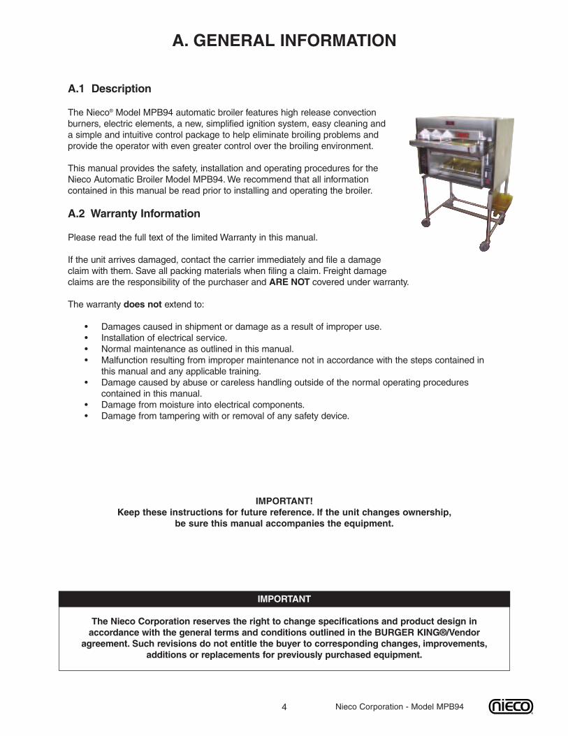
The Nieco® Model MPB94 automatic broiler features high release convectionburners, electric elements, a new, simplified ignition system, easy cleaning anda simple and intuitive control package to help eliminate broiling problems andprovide the operator with even greater control over the broiling environment.
This manual provides the safety, installation and operating procedures for theNieco Automatic Broiler Model MPB94.We recommend that all informationcontained in this manual be read prior to installing and operating the broiler.
A.2 Warranty Information
Please read the full text of the limited Warranty in this manual.
If the unit arrives damaged, contact the carrier immediately and file a damageclaim with them. Save all packing materials when filing a claim. Freight damageclaims are the responsibility of the purchaser and ARE NOT covered under warranty.
The warranty does not extend to:
• Damages caused in shipment or damage as a result of improper use.• Installation of electrical service.• Normal maintenance as outlined in this manual.• Malfunction resulting from improper maintenance not in accordance with the steps contained in
this manual and any applicable training.• Damage caused by abuse or careless handling outside of the normal operating procedures
contained in this manual.• Damage from moisture into electrical components.• Damage from tampering with or removal of any safety device.
IMPORTANT!Keep these instructions for future reference. If the unit changes ownership,
be sure this manual accompanies the equipment.
IMPORTANT
The Nieco Corporation reserves the right to change specifications and product design inaccordance with the general terms and conditions outlined in the BURGER KING®/Vendoragreement. Such revisions do not entitle the buyer to corresponding changes, improvements,
additions or replacements for previously purchased equipment.
Nieco Corporation - Model MPB94
5
A.3 Service/Technical Assistance
If you experience any problems with the installation or operation of your broiler, contact your localAuthorized Nieco Distributor.
Fill in the information bellow and have it handy when calling your authorized service agency for assistance.The serial number is on the broiler rating plate on the side of the unit.
Purchased from:
Date of Purchase:
Model No.:
Serial No.:
For the name of your local Authorized Nieco Distributor, please call (800) 821-2141.
Use only genuine Nieco replacement parts in your broiler. Use of replacement parts other than those sup-plied by Authorized Nieco Distributors and Service Agencies will void the warranty and may significantlyalter the performance of your broiler. Nieco and the Burger King Corporation have worked together to cre-ate a set of standards for broiler performance, food quality and food safety. The use of non-Nieco parts iscapable of affecting these criteria, and may affect broiler performance, parts longevity and food safety.Yourlocal Authorized Nieco Distributor and Service Agent has been factory trained and has a complete supplyof parts for your Nieco Automatic Broiler.
You may contact the factory direct at (707) 284-7100 if you have trouble locating your local NiecoDistributor.
A.4 Important Safety Information
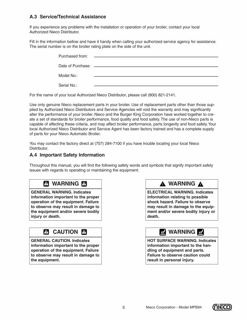
Throughout this manual, you will find the following safety words and symbols that signify important safetyissues with regards to operating or maintaining the equipment:
WARNINGGENERAL WARNING. Indicatesinformation important to the properoperation of the equipment. Failureto observe may result in damage tothe equipment and/or severe bodilyinjury or death.
WARNINGELECTRICAL WARNING. Indicatesinformation relating to possibleshock hazard. Failure to observemay result in damage to the equip-ment and/or severe bodily injury ordeath.
CAUTIONGENERAL CAUTION. Indicatesinformation important to the properoperation of the equipment. Failureto observe may result in damage tothe equipment.
WARNINGHOT SURFACE WARNING. Indicatesinformation important to the han-dling of equipment and parts.Failure to observe caution couldresult in personal injury.
Nieco Corporation - Model MPB94
6
A.4 Important Safety Information (Continued.)
In addition to the warnings and cautions in this manual, use the following guidelines for safe operation ofyour Nieco Automatic Broiler:
• Read and follow all instructions before using this equipment.• Install or locate broiler only for its intended use as described in this manual.• Do not operate this equipment if it has a damaged cord or plug, if it is not working properly or if it
has been otherwise damaged.• This equipment should only be serviced by authorized personnel. Contact your local Nieco
Distributor for adjustment or repair.• Use only genuine Nieco replacement parts for your broiler. Failure to do so will void the warranty
and may significantly alter the performance of your broiler. Nieco and the Burger KingCorporation have worked together to create a set of standards for broiler performance, food qualityand food safety. The use of non-Nieco parts is capable of affecting these criteria, and may affectbroiler performance, parts longevity and food safety.
The following warnings and cautions appear throughout the manual and should be carefullyobserved:
• Turn the broiler off, close the main gas valve, and disconnect the plug beforeperforming any service, maintenance or cleaning on the broiler.
• Always allow the broiler to fully cool before performing any service, maintenance orcleaning. Failure to wait for the broiler to cool fully may result in personal injury.
• The procedures in this manual may include reference to the use of chemical products.TheNieco Corporation does not endorse the use of any particular cleaning/degreasing agent.Use only those chemicals that are approved for use in the BURGER KING® SYSTEM.
• The broiler should be grounded according to local electrical codes to prevent thepossibility of electrical shock. It requires a grounded receptacle with separate electricallines, protected by fuses or circuit breakers of the proper rating.
• All electrical connections must be in accordance with local electrical codes and any otherapplicable codes.
• The use of adequate ventilation (as rated in this manual) with this broiler is mandatory.Failure to adequately ventilate this unit and provide safe operating distances (as specifiedin this manual) is a fire safety hazard. Follow the instructions for emergency broilershutdown in the event of an emergency.
• No attempt should be made to operate this appliance in the event of a power failure.
WARNING ELECTRICAL SHOCK HAZARD. FAILURETO FOLLOWTHESE INSTRUCTIONS COULDRESULT IN SERIOUS INJURY OR DEATH:
_ Electrical ground is required on this appliance._ Check with a qualified electrician if you are in doubt as to whether the appliance is properly
grounded._ Do not use water on or near the control box for risk of serious injury or death due to
electrical shock.
WARNING, HIGH TEMPERATURESWITH HOT SURFACES. FAILURETO FOLLOWTHESE PROCE-DURES COULD RESULT IN SERIOUS INJURY:
_ Do not attempt to clean, disassemble or perform maintenance on this broiler until it is fullycooled as per the instructions contained in this manual.
Nieco Corporation - Model MPB94
7 Nieco Corporation - Model MPB94
B. INSTALLATIONB.1 Pre-InstallationUncrate the broiler and inspect for shipping damage. Remove the tape securing the machine parts, andinstall the parts in their proper location. If there are obvious or concealed damages to any part of thebroiler, please contact your freight carrier. The factory warranty does not cover freight damage.
B.2 MountingFollow the mounting instructions if this function is not performed by the installer.
B.3 LevelingThe grease drain system is based on a gravity-flow design. Therefore, it is extremely important that thebroiler be placed on a level surface.
B.4 Hood RequirementsThis appliance must be installed under a ventilation hood of adequate size and the following minimumcapacity:
Model Minimum SCFM Recommended SCFMMPB94 700 1000
Do not obstruct the flow of combustion and ventilation air. An adequate air supply must be available forsafe and proper operation.
For installations in the Commonwealth of Massachusetts the following shall apply: Venting shall be incompliance with NFPA Section 10.3.5.2 for the Model MPB94.
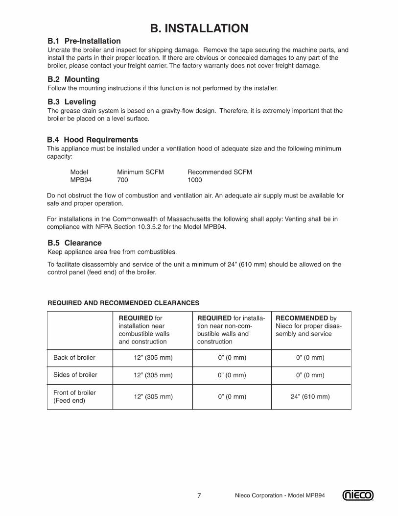
B.5 ClearanceKeep appliance area free from combustibles.
To facilitate disassembly and service of the unit a minimum of 24” (610 mm) should be allowed on thecontrol panel (feed end) of the broiler.
REQUIRED forinstallation nearcombustible wallsand construction
REQUIRED for installa-tion near non-com-bustible walls andconstruction
RECOMMENDED byNieco for proper disas-sembly and service
Back of broiler
Sides of broiler
Front of broiler(Feed end)
REQUIRED AND RECOMMENDED CLEARANCES
12” (305 mm) 0” (0 mm)
0” (0 mm)
24” (610 mm)
0” (0 mm)
0” (0 mm)
0” (0 mm)
12” (305 mm)
12” (305 mm)
8
B.6 Gas Connection- 3/4” N.P.T.At rated input the gas supply should deliver a minimum pressure of at least 15 mbar (6" water column)at the broiler connection for natural gas. Incoming gas supply pressure must not exceed 50 mbar (14"water column).
Note: The installation of this appliance must conform with local codes, or in the absence of local codes,with the National Fuel Gas Code, ANSI Z223.1, Natural Gas Installation Code, CAN/CGA-B149.1including:
1. The appliance and its individual shutoff valve must be disconnected from the gas supplypiping system during any pressure testing of that system at test pressures in excess of1/2 psi (3.45 kPa).
2. The appliance must be isolated from the gas supply piping system by closing itsindividual manual shutoff valve during any pressure testing of the gas supply pipingsystem at test pressures equal to or less than 1/2 psi (3.45 kPa).
By public initiative, the State of California has adopted legislation (Proposition 65) which requiresmanufacturers of many types of products, including gas appliances, to warn consumers of theirproducts that contain chemicals or produce substances listed by the State of California to eithercause cancer, birth defects or other reproductive harm.
Nieco Corporation - Model MPB94
For safety in the kitchen area, and to insure maximum service life, it is vitally important to correctly installconnectors. The connector shall comply with the Standard for Connectors for Moveable Gas Appliances,ANSI Z21.69 or CAN/CGA-6.16 and a quick disconnect device that complies with the Standard for Quick-Disconnect Devices for use with gas fuel, ANSI Z21.41 or CAN1-6.9
In order to avoid sharp kinks or excessive bends that could have a damaging effect on the connector, itmay be necessary to attach pipe elbows in order to bring the connector into its proper plane. For easymovement of the appliance, the connector should be installed with a "lazy" loop for minimum tension.
Note: Gas appliances should be disconnected prior to maximum movement. (Minimal movement ispossible to connect hose.)
B.7 Installing Gas Appliance Connectors and Flexible Gas Lines Correctly
WARNINGIf not installed, operated and maintained in accordance with the manufacturers instructions, thisproduct could expose you to substances in fuel or from fuel combustion which can cause cancer,birth defects or other reproductive harm.
9 Nieco Corporation - Model MPB94
B.9 Electrical ConnectionPower requirements are stated on the unit nameplate and must be connected accordingly. This appli-ance, when installed must be electrically grounded in accordance with local codes, or in the absence oflocal codes, with the National Electrical Code, ANSI/NFPA 70, or the Canadian Electrical Code, CSAC22.2, as applicable. Before starting broiler, tighten all electrical connections in control box. An electricalwiring diagram can be found inside the control box.
Note: Disconnect power before servicing.
B.10 Pre-Operation CheckBe sure that all parts are installed in the proper location:
� Ventilation is turned on� Broiler is plugged in� Gas line is connected
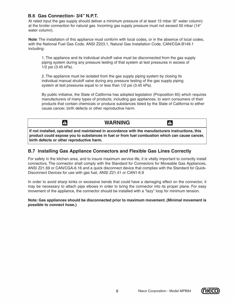
B.8 Restraining Device Installation and UseThis high strength restrainer is to be used with all moveable (castered) appliances. It fully complies withAmerican Gas Association requirements. References: Z21.69, Z83.11, and Z21.41 with current revisions.Installation is quick and positive. In Canada, device is in accordance with CAN 1-6.9-M70 QuickDisconnect Devices for use with gas fuel, and CAN 1-6.10-88 metal connectors for gas appliances.Correct length for any appliance is simply a matter of loosening two adjuster clips (1) and re-tightening.(3" to 6" shorter than appliance connector is desired length.) Restrainer is made of heavy duty steelcable, with a strong scissor hood (2) at one end, and an equally strong spring hook (3) at the other.Cotter pin (4) is supplied to secure the installation. For proper attachment to the broiler, use the suppliedhardware to attach the device to the holes in the shear plate of the broiler stand.
NOTE: If disconnection of the restraint is necessary, reconnect the restraint after the appliance
has been returned to its originally installed position.
10
C. OPERATION
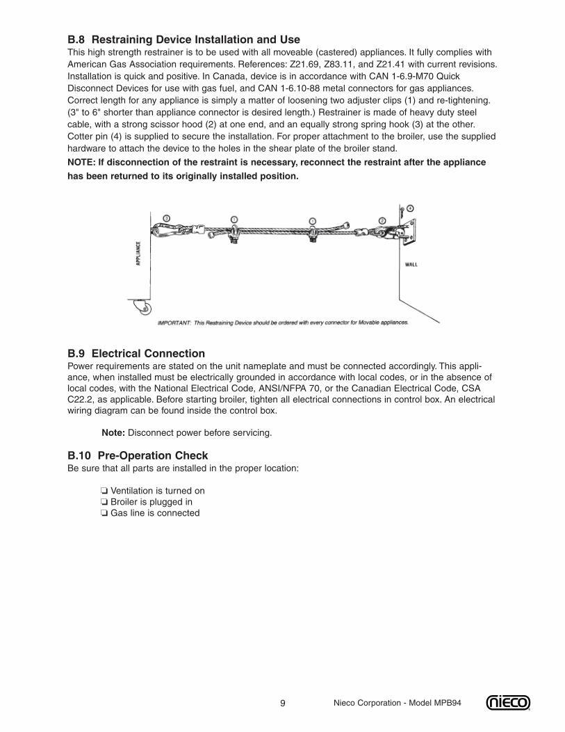
C.1 Controls and Indicators for broilers not equipped with the Energy Management System(EMS)
ON THE MAIN SIDEIgnition Failure LightP/N 17201
Belt Speed ControlP/N 13727
Load Sensing ControlP/N 13570-B
On/Off Indicator LightP/N 4100
Main On/Off SwitchP/N 15480
ON THE FLEX SIDE
Multi Product ControlP/N 15161
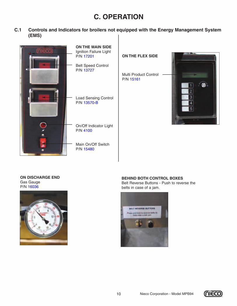
ON DISCHARGE ENDGas GaugeP/N 16036
BEHIND BOTH CONTROL BOXESBelt Reverse Buttons - Push to reverse thebelts in case of a jam.
Nieco Corporation - Model MPB94
11 Nieco Corporation - Model MPB94
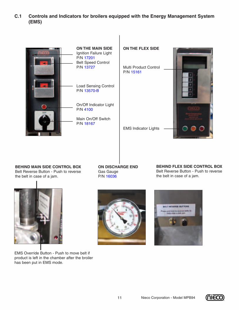
C.1 Controls and Indicators for broilers equipped with the Energy Management System(EMS)
ON THE MAIN SIDEIgnition Failure LightP/N 17201Belt Speed ControlP/N 13727
Load Sensing ControlP/N 13570-B
On/Off Indicator LightP/N 4100
Main On/Off SwitchP/N 18167
ON THE FLEX SIDE
Multi Product ControlP/N 15161
EMS Indicator Lights
ON DISCHARGE ENDGas GaugeP/N 16036
BEHIND FLEX SIDE CONTROL BOXBelt Reverse Button - Push to reversethe belt in case of a jam.
BEHIND MAIN SIDE CONTROL BOXBelt Reverse Button - Push to reversethe belt in case of a jam.
EMS Override Button - Push to move belt ifproduct is left in the chamber after the broilerhas been put in EMS mode.
12
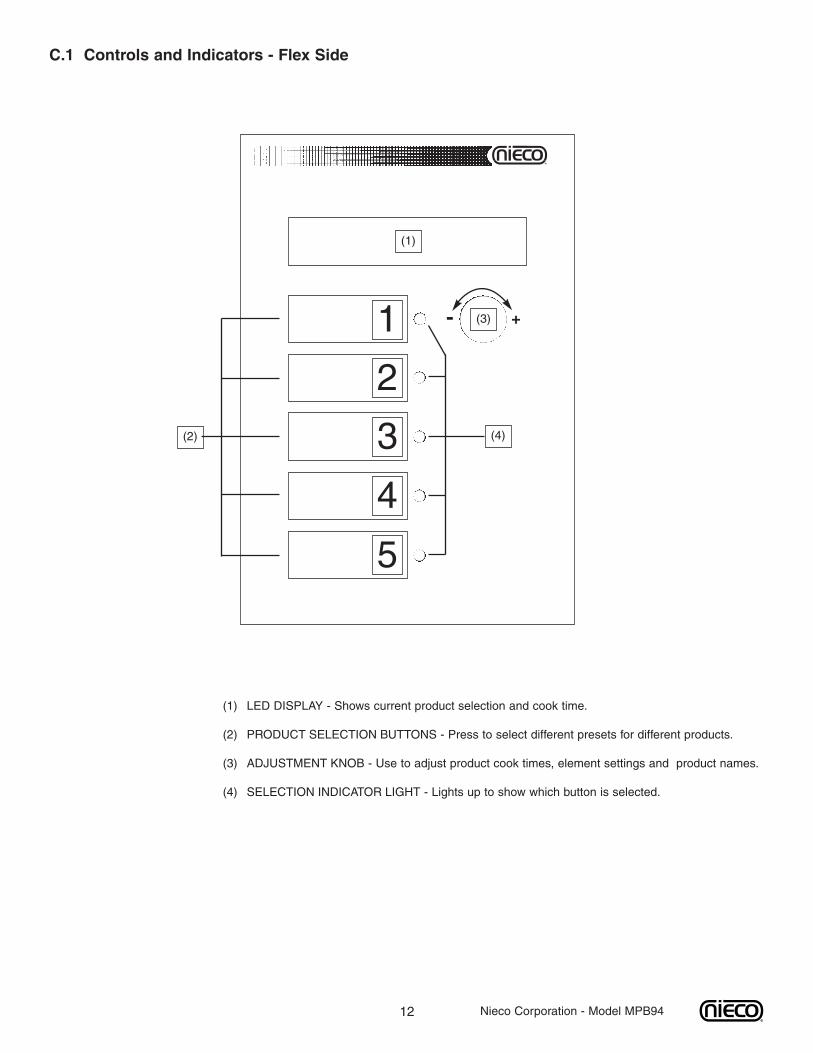
C.1 Controls and Indicators - Flex Side
(1) LED DISPLAY - Shows current product selection and cook time.
(2) PRODUCT SELECTION BUTTONS - Press to select different presets for different products.
(3) ADJUSTMENT KNOB - Use to adjust product cook times, element settings and product names.
(4) SELECTION INDICATOR LIGHT - Lights up to show which button is selected.
1
2
3
4
5
- +
(1)
(2) (4)
(3)
Nieco Corporation - Model MPB94
13
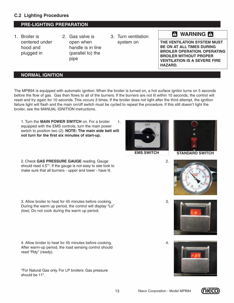
C.2 Lighting Procedures
1. Broiler iscentered underhood andplugged in
2. Gas valve isopen whenhandle is in line(parallel to) thepipe
3. Turn ventilationsystem on
The MPB94 is equipped with automatic ignition. When the broiler is turned on, a hot surface ignitor turns on 5 secondsbefore the flow of gas. Gas then flows to all of the burners. If the burners are not lit within 10 seconds, the control willreset and try again for 10 seconds. This occurs 3 times. If the broiler does not light after the third attempt, the ignitionfailure light will flash and the main on/off switch must be cycled to repeat the procedure. If this still doesn’t light thebroiler, see the MANUAL IGNITION instructions.
WARNINGTHE VENTILATION SYSTEM MUSTBE ON AT ALL TIMES DURINGBROILER OPERATION. OPERATINGBROILERWITHOUT PROPERVENTILATION IS A SEVERE FIREHAZARD.
NORMAL IGNITION
PRE-LIGHTING PREPARATION
Nieco Corporation - Model MPB94
1. Turn the MAIN POWER SWITCH on. For a broilerequipped with the EMS controls, turn the main powerswitch to position two (2). NOTE: The main side belt willnot turn for the first six minutes of start-up.
1.
EMS SWITCH STANDARD SWITCH
2.
3.
4.
2. Check GAS PRESSURE GAUGE reading. Gaugeshould read 4.5”*. If the gauge is not easy to see look tomake sure that all burners - upper and lower - have lit.
3. Allow broiler to heat for 45 minutes before cooking.During the warm up period, the control will display “Lo”(low). Do not cook during the warm up period.
4. Allow broiler to heat for 45 minutes before cooking.After warm-up period, the load sensing control shouldread “Rdy” (ready).
*For Natural Gas only. For LP broilers: Gas pressureshould be 11”.
14
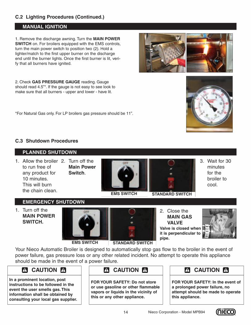
C.2 Lighting Procedures (Continued.)
MANUAL IGNITION
Nieco Corporation - Model MPB94
1. Allow the broilerto run free ofany product for10 minutes.This will burnthe chain clean.
2. Turn off theMain PowerSwitch.
3. Wait for 30minutesfor thebroiler tocool.
C.3 Shutdown Procedures
PLANNED SHUTDOWN
2. Close theMAIN GASVALVE
Valve is closed whenit is perpendicular topipe.
EMERGENCY SHUTDOWN
1. Turn off theMAIN POWERSWITCH.
Your Nieco Automatic Broiler is designed to automatically stop gas flow to the broiler in the event ofpower failure, gas pressure loss or any other related incident. No attempt to operate this applianceshould be made in the event of a power failure.
CAUTION
In a prominent location, postinstructions to be followed in theevent the user smells gas. Thisinformation shall be obtained byconsulting your local gas supplier.
CAUTION
FORYOUR SAFETY: Do not storeor use gasoline or other flammablevapors or liquids in the vicinity ofthis or any other appliance.
CAUTION
FORYOUR SAFETY: In the event ofa prolonged power failure, noattempt should be made to operatethis appliance.
1. Remove the discharge awning. Turn the MAIN POWERSWITCH on. For broilers equipped with the EMS controls,turn the main power switch to position two (2). Hold alighter/match to the first upper burner on the dischargeend until the burner lights. Once the first burner is lit, veri-fy that all burners have ignited.
2. Check GAS PRESSURE GAUGE reading. Gaugeshould read 4.5”*. If the gauge is not easy to see look tomake sure that all burners - upper and lower - have lit.
*For Natural Gas only. For LP broilers gas pressure should be 11”.
EMS SWITCH STANDARD SWITCH
EMS SWITCH STANDARD SWITCH

15
C.4 Control Operation
IMPORTANT: THIS BROILER IS SHIPPED WITH FACTORY PRESETS THAT MUST BE CHANGED.If this is the initial start-up for your broiler, ALL control settings must be made according to BURGER KING® specifications. Follow thesteps outlined for calibration, changing preset times and setting the flex chamber element heat settings to properly set up this broiler.
Nieco Corporation - Model MPB94
MAIN SIDE CONTROLS
- +
2:301. SETTING BELT SPEEDSLift cover, press and turn the belt speedcontrol knob to the desired speed setting.
2. LOAD SENSING CONTROLHow it works:The load sensing control will display“Rdy” (ready) when the broiler is ready tocook on.
3. AUTOMATIC CALIBRATIONA. Before turning the broiler on, pressand hold the load sensing control knobin.
B. Turn the main power switch on andcontinue to hold the load sensing controlknob in for 5 seconds.
C. After 5 seconds, release the knob. Thecontrol will display a countdown of 60minutes. After the countdown, the controlwill display “Rdy” (ready), and the broilerwill be calibrated.
IMPORTANT: DO NOT COOK DURINGTHE 60 MINUTE COUNTDOWN!
Press and hold for5 seconds
Automaticcalibration
- +
�A
- +
- +
60
Rdy
�B
C
Display will show60 minutecountdown
16 Nieco Corporation - Model MPB94
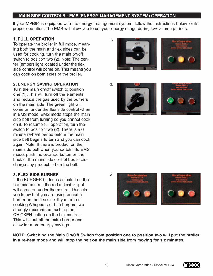
MAIN SIDE CONTROLS - EMS (ENERGY MANAGEMENT SYSTEM) OPERATION
1. FULL OPERATIONTo operate the broiler in full mode, mean-ing both the main and flex sides can beused for cooking, turn the main on/offswitch to position two (2). Note: The cen-ter (amber) light located under the flexside control will come on. This means youcan cook on both sides of the broiler.
2. ENERGY SAVING OPERATIONTurn the main on/off switch to positionone (1). This will turn off the elementsand reduce the gas used by the burnerson the main side. The green light willcome on under the flex side control whenin EMS mode. EMS mode stops the mainside belt from turning so you cannot cookon it. To resume full operation, turn theswitch to position two (2). There is a 6minute re-heat period before the mainside belt begins to turn and you can cookagain. Note: If there is product on themain side belt when you switch into EMSmode, push the override button on theback of the main side control box to dis-charge any product left on the belt.
3. FLEX SIDE BURNERIf the BURGER button is selected on theflex side control, the red indicator lightwill come on under the control. This letsyou know that you are using an extraburner on the flex side. If you are notcooking Whoppers or hamburgers, westrongly recommend pushing theCHICKEN button on the flex control.This will shut off the extra burner andallow for more energy savings.
NOTE: Switching the Main On/Off Switch from position one to position two will put the broilerin a re-heat mode and will stop the belt on the main side from moving for six minutes.
If your MPB94 is equipped with the energy management system, follow the instructions below for itsproper operation. The EMS will allow you to cut your energy usage during low volume periods.
1.
2.
3.
17 Nieco Corporation - Model MPB94
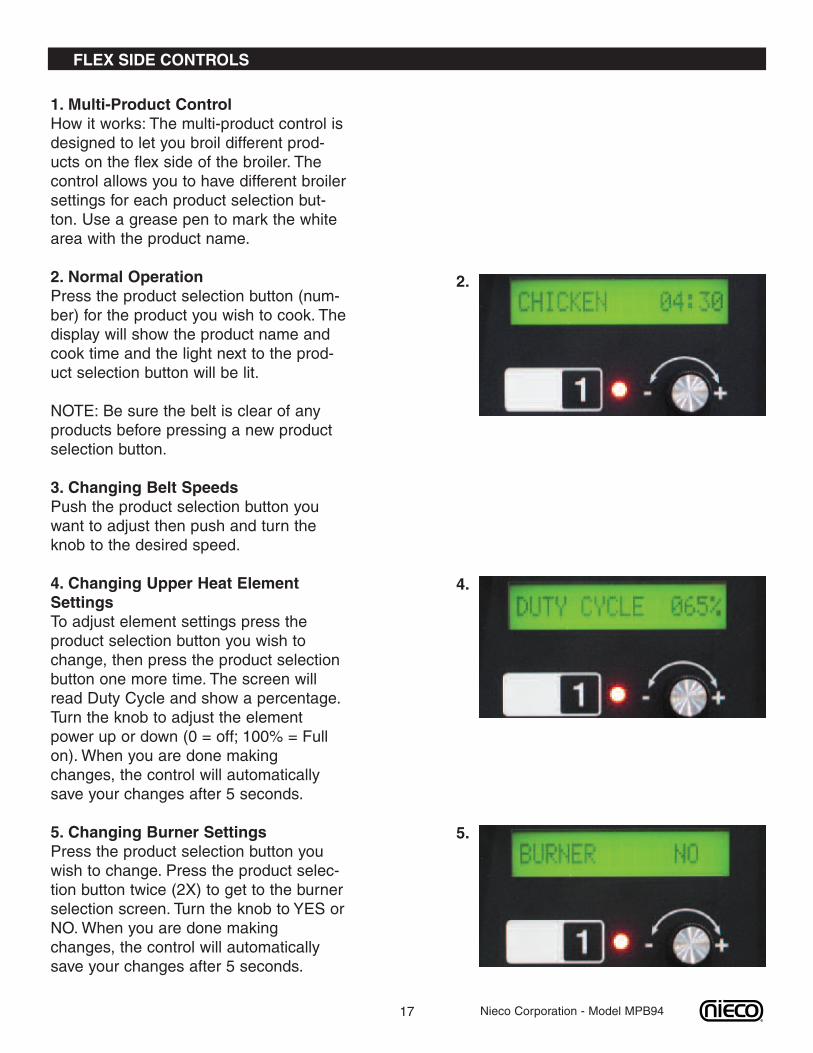
FLEX SIDE CONTROLS
1. Multi-Product ControlHow it works: The multi-product control isdesigned to let you broil different prod-ucts on the flex side of the broiler. Thecontrol allows you to have different broilersettings for each product selection but-ton. Use a grease pen to mark the whitearea with the product name.
2. Normal OperationPress the product selection button (num-ber) for the product you wish to cook. Thedisplay will show the product name andcook time and the light next to the prod-uct selection button will be lit.
NOTE: Be sure the belt is clear of anyproducts before pressing a new productselection button.
3. Changing Belt SpeedsPush the product selection button youwant to adjust then push and turn theknob to the desired speed.
4. Changing Upper Heat ElementSettingsTo adjust element settings press theproduct selection button you wish tochange, then press the product selectionbutton one more time. The screen willread Duty Cycle and show a percentage.Turn the knob to adjust the elementpower up or down (0 = off; 100% = Fullon). When you are done makingchanges, the control will automaticallysave your changes after 5 seconds.
5. Changing Burner SettingsPress the product selection button youwish to change. Press the product selec-tion button twice (2X) to get to the burnerselection screen. Turn the knob to YES orNO.When you are done makingchanges, the control will automaticallysave your changes after 5 seconds.
2.
4.
5.

18 Nieco Corporation - Model MPB94
FLEX SIDE CONTROLS
6. Changing Product NamesPush the product selection button whichyou want to make a name to. Press andhold the KNOB in for 15 seconds. Thecontrol will enter the edit name screen forthat button. Turn the knob to change thecharacters. Press the knob once to moveto the next character until you are fin-ished editing the product name for thatbutton (10 character limit). Press andhold the PRODUCT SELECTION BUT-TON for 5 seconds to save the changesand return to normal operation.
7. Factory PresetsThe MPB94 uses the following factorypresets for the Multi-Product Control:
ProductSelection Button
Product Name Cook Time Duty Cycle Burner Yes/No
1 Chicken 5:00 100% NO
2 Steakhouse 2:40 100% YES
3 Product 3 7:00 50% NO
4 Product 4 7:00 50% NO
5 Burger 2:15 100% YES
6
19
D. CLEANING AND DISASSEMBLYTurn broiler off and close the main gas valve. Disconnect the power supply to the broiler before cleaning orservicing. If this broiler is connected using a restraint, and disconnection of the restraint is necessary for clean-ing or moving the broiler, the restraint must be reconnected after the broiler has been returned to its originallyinstalled position. Allow to cool for 30 minutes prior to cleaning/disassembly. Leave the ventilation system onduring cooling. Use only approved cleaning, degreasing and sanitizing solutions.
ALL PARTS ARE CLEANED ON A DAILY BASIS UNLESS OTHERWISE NOTED
Follow the steps for proper disassembly. Reverse the order for reassembly.
CAUTION
Follow the Disassembly andReassembly steps to ensure properoperation of the broiler. Failure todo so may result in operationalproblems.
WARNINGBROILER PARTS ARE HOT. DONOT ATTEMPT TO DISASSEMBLETHE BROILER UNTIL IT IS FULLYCOOL. FAILURE TO FOLLOWTHISINSTRUCTION MAY RESULT INSEVERE INJURY.
WARNING
LEAVE THE VENTILATION HOODON DURING COOLING. FAILURE TODO SO COULD POSE A FIRESAFETY HAZARD.
Nieco Corporation - Model MPB94
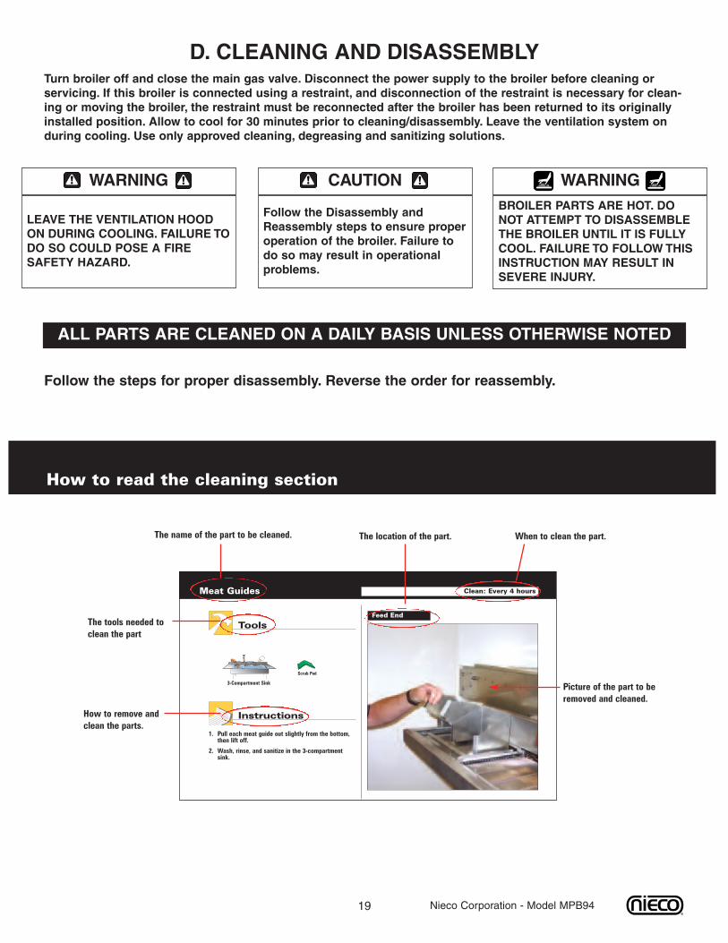
How to read the cleaning section
The location of the part.
Pull each meat guide out slightly from the bottom,then lift off.
Wash, rinse, and sanitize in the 3-compartmentsink.
Meat Guides
Feed End
Tools
Instructions
3-Compartment Sink
Clean: Every 4 hours
1.
2.
Scrub Pad
When to clean the part.
Picture of the part to beremoved and cleaned.
How to remove andclean the parts.
The tools needed toclean the part
The name of the part to be cleaned.
20 Nieco Corporation - Model MPB94
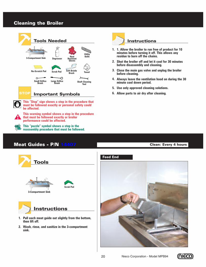
Instructions
1. Allow the broiler to run free of product for 10minutes before turning it off. This allows anyresidue to burn off the chains.
Shut the broiler off and let it cool for 30 minutesbefore disassembly and cleaning.
Close the main gas valve and unplug the broilerbefore cleaning.
Always leave the ventilation hood on during the 30minute cool down period.
Use only approved cleaning solutions.
Allow parts to air dry after cleaning.
Cleaning the Broiler
3-Compartment Sink
No-Scratch Pad Scrub Pad Towel
HeatResistantGloves
Degreaser
Soft BristleBrush
UtilityKnife
Small OrificeBrush Shaft Cleaning
Tool
Tools Needed
1.
2.
This “Stop” sign shows a step in the procedure thatmust be followed exactly or personal safety couldbe affected.
This warning symbol shows a step in the procedurethat must be followed exactly or broilerperformance could be affected.
This “puzzle” symbol shows a step in thereassembly procedure that must be followed.
3.
4.
5.
!
Important SymbolsSTOP 6.
Large OrificeBrush
Pull each meat guide out slightly from the bottom,then lift off.
Wash, rinse, and sanitize in the 3-compartmentsink.
Meat Guides - P/N 14407
Feed End
Tools
Instructions
3-Compartment Sink
Clean: Every 4 hours
1.
2.
Scrub Pad
21 Nieco Corporation - Model MPB94
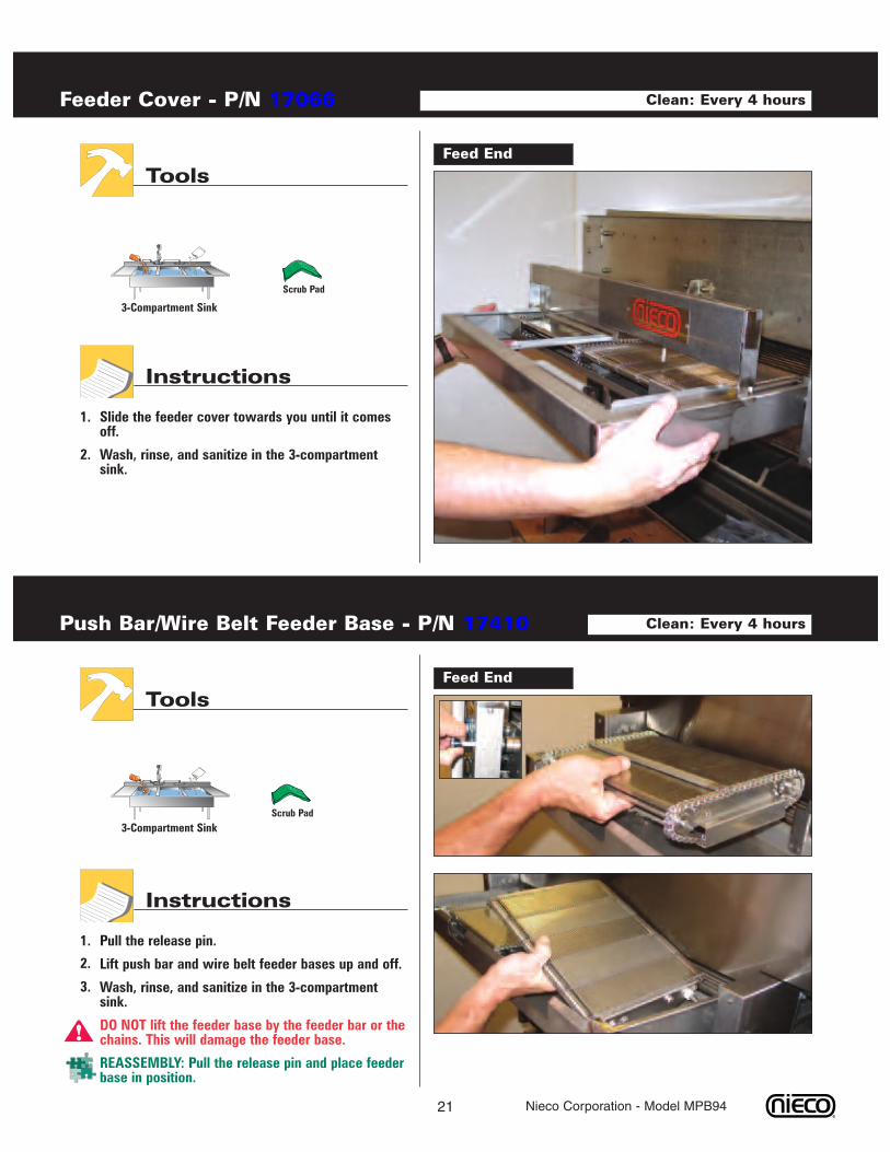
Slide the feeder cover towards you until it comesoff.
Wash, rinse, and sanitize in the 3-compartmentsink.
Feeder Cover - P/N 17066
Feed End
Tools
Instructions
3-Compartment Sink
Clean: Every 4 hours
1.
2.
Pull the release pin.
Lift push bar and wire belt feeder bases up and off.
Wash, rinse, and sanitize in the 3-compartmentsink.
DO NOT lift the feeder base by the feeder bar or thechains. This will damage the feeder base.
REASSEMBLY: Pull the release pin and place feederbase in position.
Push Bar/Wire Belt Feeder Base - P/N 17410
Feed End
Tools
Instructions
3-Compartment Sink
Clean: Every 4 hours
1.
2.
3.
!
Scrub Pad
Scrub Pad
22 Nieco Corporation - Model MPB94
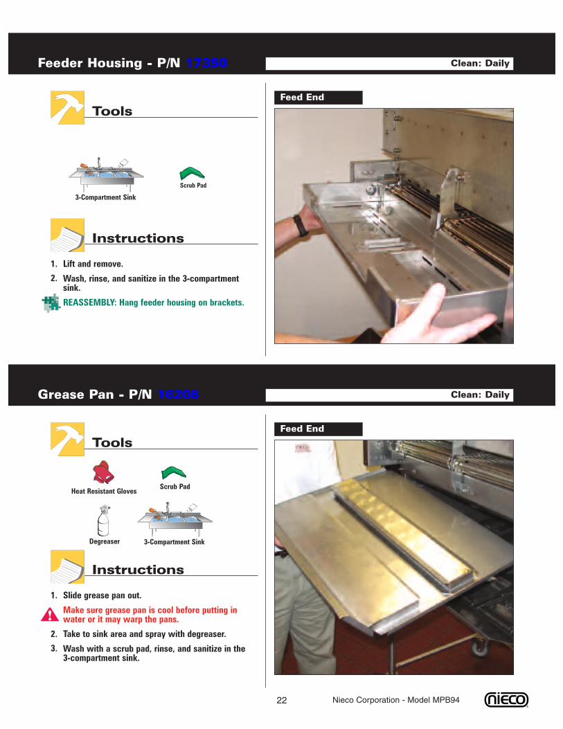
Lift and remove.
Wash, rinse, and sanitize in the 3-compartmentsink.
REASSEMBLY: Hang feeder housing on brackets.
Feeder Housing - P/N 17350
Feed End
Tools
Instructions
3-Compartment Sink
Clean: Daily
1.
2.
Slide grease pan out.
Make sure grease pan is cool before putting inwater or it may warp the pans.
Take to sink area and spray with degreaser.
Wash with a scrub pad, rinse, and sanitize in the3-compartment sink.
Grease Pan - P/N 16208
Feed End
Tools
Instructions
Clean: Daily
3-Compartment Sink
Scrub PadHeat Resistant Gloves
Degreaser
1.
2.
3.
!
Scrub Pad
23 Nieco Corporation - Model MPB94
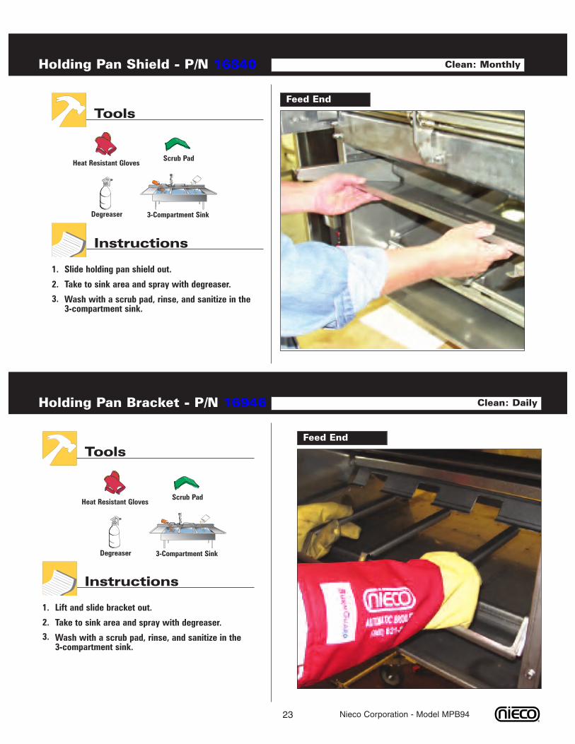
Slide holding pan shield out.
Take to sink area and spray with degreaser.
Wash with a scrub pad, rinse, and sanitize in the3-compartment sink.
Holding Pan Shield - P/N 16840
Feed End
Tools
Instructions
Clean: Monthly
3-Compartment Sink
Scrub PadHeat Resistant Gloves
Degreaser
1.
2.
3.
Lift and slide bracket out.
Take to sink area and spray with degreaser.
Wash with a scrub pad, rinse, and sanitize in the3-compartment sink.
Holding Pan Bracket - P/N 16946
Feed End
Tools
Instructions
Clean: Daily
1.
2.
3.
3-Compartment Sink
Scrub PadHeat Resistant Gloves
Degreaser
24 Nieco Corporation - Model MPB94
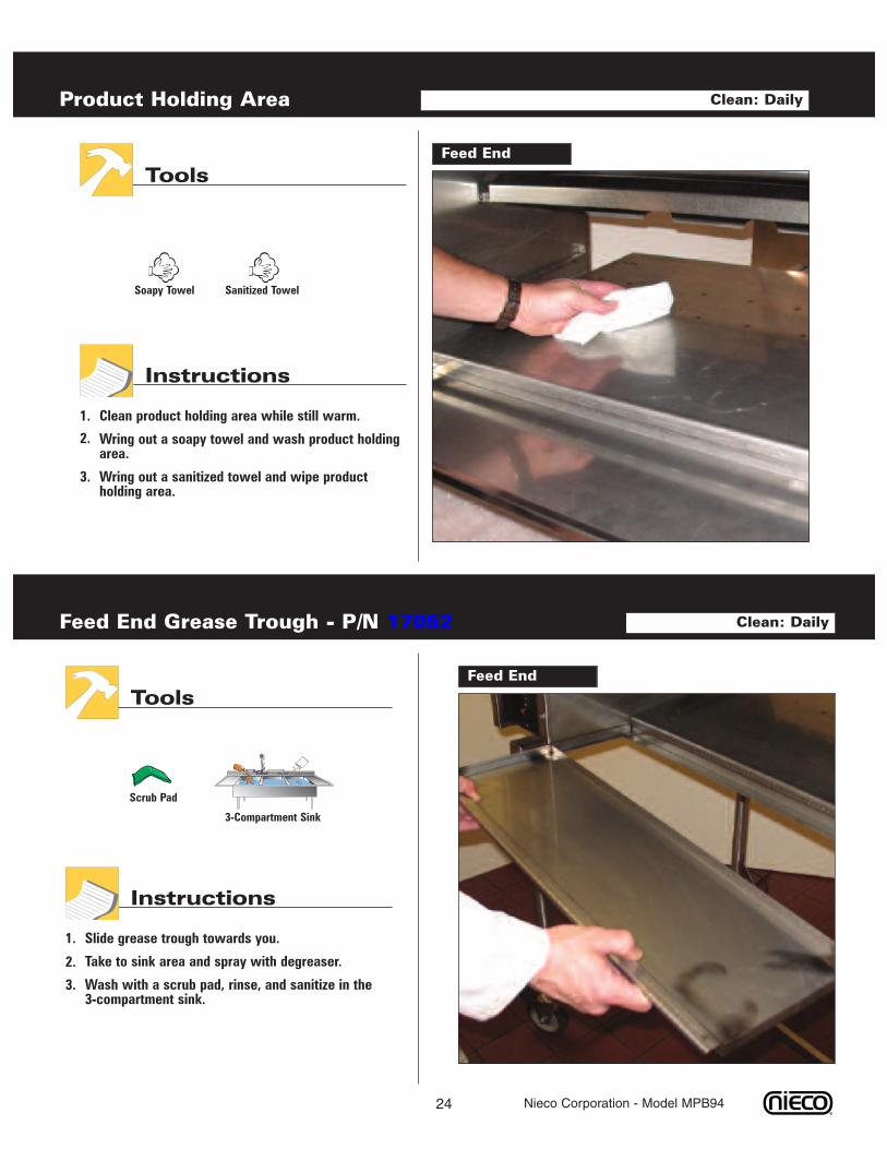
Clean product holding area while still warm.
Wring out a soapy towel and wash product holdingarea.
Wring out a sanitized towel and wipe productholding area.
Product Holding Area
Feed End
Tools
Instructions
Soapy Towel
Clean: Daily
1.
2.
3.
Sanitized Towel
Slide grease trough towards you.
Take to sink area and spray with degreaser.
Wash with a scrub pad, rinse, and sanitize in the3-compartment sink.
Feed End Grease Trough - P/N 17052
Feed End
Tools
Instructions
Clean: Daily
1.
2.
3.
3-Compartment Sink
Scrub Pad
25 Nieco Corporation - Model MPB94
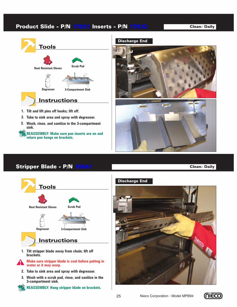
Tilt and lift pins off hooks; lift off.
Take to sink area and spray with degreaser.
Wash, rinse, and sanitize in the 3-compartmentsink.
REASSEMBLY: Make sure pan inserts are on andreturn pan hangs on brackets.
Product Slide - P/N 17031 Inserts - P/N 17032
Discharge End
Tools
Instructions
Clean: Daily
1.
2.
3.
3-Compartment Sink
Scrub PadHeat Resistant Gloves
Degreaser
Tilt stripper blade away from chain; lift offbrackets.
Make sure stripper blade is cool before putting inwater or it may warp.
Take to sink area and spray with degreaser.
Wash with a scrub pad, rinse, and sanitize in the3-compartment sink.
REASSEMBLY: Hang stripper blade on brackets.
Stripper Blade - P/N 15661
Discharge End
Tools
Instructions
Clean: Daily
3-Compartment Sink
Scrub PadHeat Resistant Gloves
Degreaser
1.
2.
3.
!
26 Nieco Corporation - Model MPB94
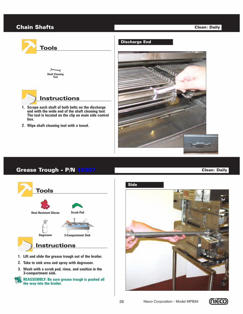
Scrape each shaft of both belts on the dischargeend with the wide end of the shaft cleaning tool.The tool is located on the clip on main side controlbox.
Wipe shaft cleaning tool with a towel.
Chain Shafts
Discharge End
Tools
Instructions
Clean: Daily
1.
2.
Shaft CleaningTool
Lift and slide the grease trough out of the broiler.
Take to sink area and spray with degreaser.
Wash with a scrub pad, rinse, and sanitize in the3-compartment sink.
REASSEMBLY: Be sure grease trough is pushed allthe way into the broiler.
Grease Trough - P/N 16307
Side
Tools
Instructions
Clean: Daily
1.
2.
3.
3-Compartment Sink
Scrub PadHeat Resistant Gloves
Degreaser
27 Nieco Corporation - Model MPB94
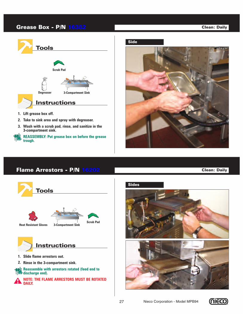
Lift grease box off.
Take to sink area and spray with degreaser.
Wash with a scrub pad, rinse, and sanitize in the3-compartment sink.
REASSEMBLY: Put grease box on before the greasetrough.
Grease Box - P/N 16382
Side
Tools
Instructions
Clean: Daily
1.
3-Compartment Sink
Scrub Pad
Degreaser
2.
3.
2.
Slide flame arrestors out.
Rinse in the 3-compartment sink.
Reassemble with arrestors rotated (feed end todischarge end).
NOTE: THE FLAME ARRESTORS MUST BE ROTATEDDAILY.
Flame Arrestors - P/N 16202
Sides
Tools
Instructions
Clean: Daily
1.
3-Compartment SinkScrub Pad
Heat Resistant Gloves
!
28 Nieco Corporation - Model MPB94
3-Compartment Sink
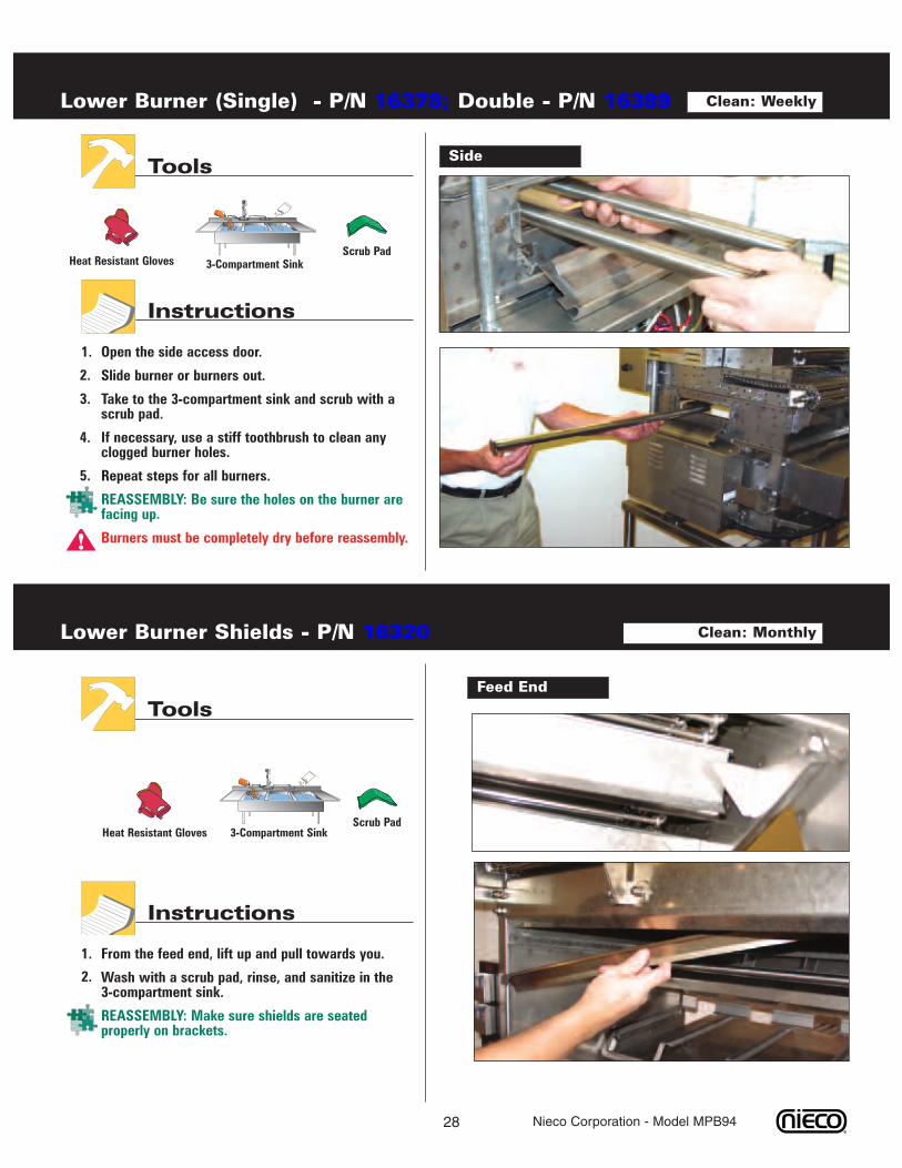
Open the side access door.
Slide burner or burners out.
Take to the 3-compartment sink and scrub with ascrub pad.
If necessary, use a stiff toothbrush to clean anyclogged burner holes.
Repeat steps for all burners.
REASSEMBLY: Be sure the holes on the burner arefacing up.
Burners must be completely dry before reassembly.
Lower Burner (Single) - P/N 16378; Double - P/N 16389
SideTools
Instructions
Clean: Weekly
Heat Resistant Gloves
1.
2.
3.
4.
5.
Scrub Pad
!
From the feed end, lift up and pull towards you.
Wash with a scrub pad, rinse, and sanitize in the3-compartment sink.
REASSEMBLY: Make sure shields are seatedproperly on brackets.
Lower Burner Shields - P/N 16320
Feed End
Tools
Instructions
3-Compartment SinkScrub Pad
Clean: Monthly
Heat Resistant Gloves
1.
2.
29 Nieco Corporation - Model MPB94
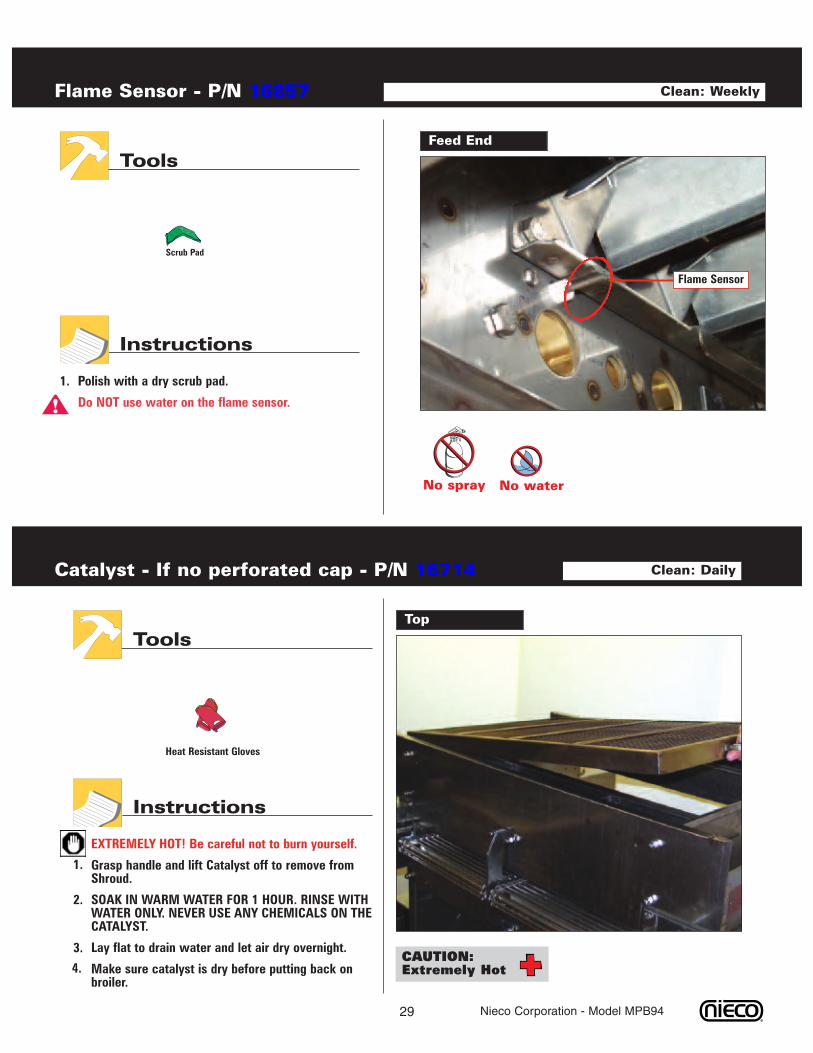
Polish with a dry scrub pad.
Do NOT use water on the flame sensor.
Flame Sensor - P/N 16857
Feed End
Tools
Instructions
Clean: Weekly
1.
Flame Sensor
No spray No water
!
Scrub Pad
EXTREMELY HOT! Be careful not to burn yourself.
Grasp handle and lift Catalyst off to remove fromShroud.
SOAK IN WARM WATER FOR 1 HOUR. RINSE WITHWATER ONLY. NEVER USE ANY CHEMICALS ON THECATALYST.
Lay flat to drain water and let air dry overnight.
Make sure catalyst is dry before putting back onbroiler.
Catalyst - If no perforated cap - P/N 16714
Top
Tools
Instructions
Heat Resistant Gloves
Clean: Daily
CAUTION:Extremely Hot
1.
2.
3.
4.
30 Nieco Corporation - Model MPB94
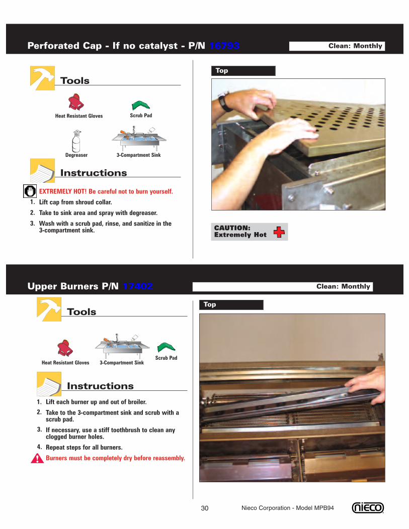
EXTREMELY HOT! Be careful not to burn yourself.
Lift cap from shroud collar.
Take to sink area and spray with degreaser.
Wash with a scrub pad, rinse, and sanitize in the3-compartment sink.
Perforated Cap - If no catalyst - P/N 16793
Top
Tools
Instructions
Clean: Monthly
3-Compartment Sink
Scrub PadHeat Resistant Gloves
Degreaser
1.
CAUTION:Extremely Hot
2.
3.
Lift each burner up and out of broiler.
Take to the 3-compartment sink and scrub with ascrub pad.
If necessary, use a stiff toothbrush to clean anyclogged burner holes.
Repeat steps for all burners.
Burners must be completely dry before reassembly.
Upper Burners P/N 17402
TopTools
Instructions
Clean: Monthly
1.
2.
3.
4.
!
3-Compartment SinkScrub Pad
Heat Resistant Gloves
31 Nieco Corporation - Model MPB94
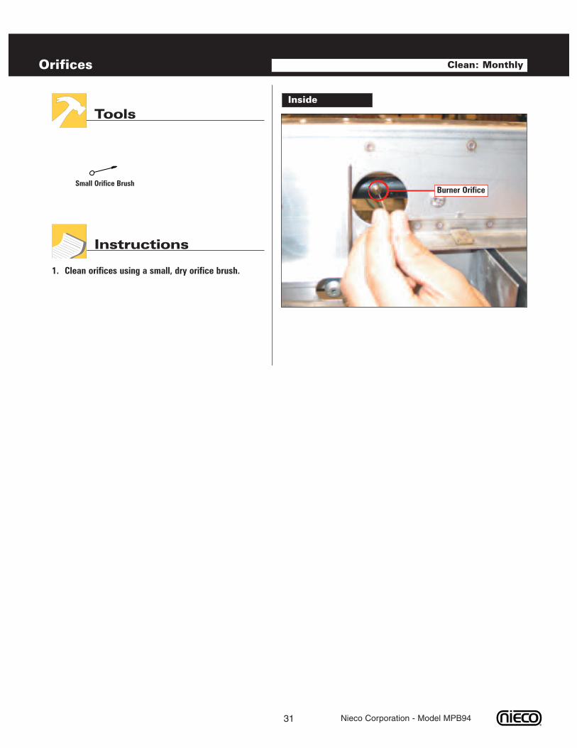
Clean orifices using a small, dry orifice brush.
Orifices
Inside
Tools
Instructions
Small Orifice Brush
Clean: Monthly
1.
Burner Orifice
E. TROUBLESHOOTING
32
Always verify that the broiler is properly assembled, the hood is on, gas valve open and broiler is plugged in.
Nieco Corporation - Model MPB94
No power to broiler when the switch is turned on.
Broiler has power, but the burners do not light.
Red light blinking on left control box.
Hot surface ignitor does not heat.
Power is on, broiler is lit, but the conveyor belts are notturning.
Load Sensing Control (LSC) stays in “Lo” even thoughthe broiler is warmed up.
Feeder belt not moving.
Feeder jams.
Burgers sticking to slide or stripper blade.
COOKING PROBLEMSBurgers under or over cooked.
Excessive flaming in broiler.
Check: Broiler is plugged in.Ventilation hood is on.Circuit Breaker on wall panel is on.
Check: Ventilation hood is on.Gas line is properly plugged in.Manual gas valve (if equipped) is on.Burners are installed properly.Burners are clean and dry.Flame sensor wire connection.
Follow manual lighting instructions.
Check the items above for burners not lighting.Turn power off and on again to reset ignition.Follow manual lighting instructions.
Check for loose wires connecting the hot surface ignitor.Follow manual lighting instructions.
Check for a jam in the conveyor belt. Check the stripperblade and the flame arrestors to make sure they areinstalled properly.
Lower the set point by holding in the knob for 5seconds, then setting the set point to match the actualtemperature. Refer to the calibration instructions in thismanual.
Make sure the feeder is assembled properly.Check for jam.Make sure the drive pin is engaged.
Make sure the burgers are not frozen together.
Clean the slide and stripper blade very thoroughly.Check cookout temperature (undercooking).
Main side: adjust conveyor belt speed.Flex side: adjust conveyor speed, duty cycle, and burnersettings.Clean burners and orifices.
Clean or rotate the flame arrestors,Clean the catalyst if equipped.Check the hood for proper operation.Check product for overcooking.
33 Nieco Corporation - Model MPB94
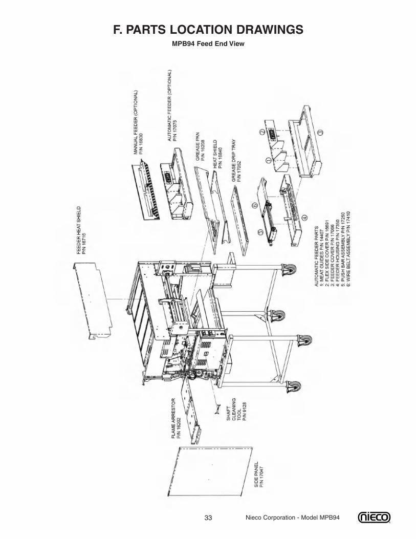
F. PARTS LOCATION DRAWINGSMPB94 Feed End View
34 Nieco Corporation - Model MPB94
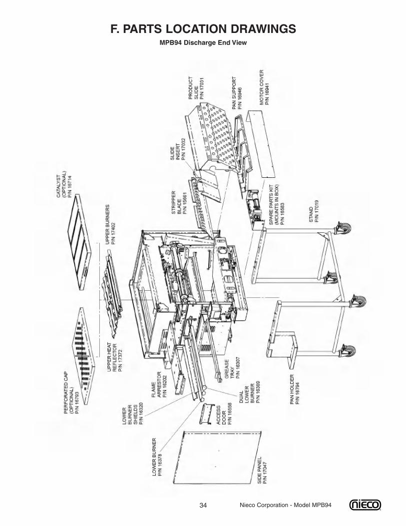
F. PARTS LOCATION DRAWINGSMPB94 Discharge End View
35 Nieco Corporation - Model MPB94
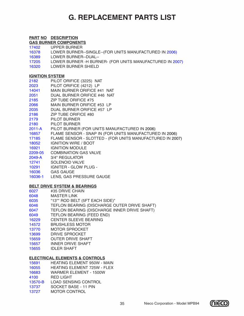
G. REPLACEMENT PARTS LIST
PART NO DESCRIPTIONGAS BURNER COMPONENTS17402 UPPER BURNER16378 LOWER BURNER--SINGLE--(FOR UNITS MANUFACTURED IN 2006)16389 LOWER BURNER--DUAL--17205 LOWER BURNER -H BURNER- (FOR UNITS MANUFACTURED IN 2007)16320 LOWER BURNER SHIELD
IGNITION SYSTEM218220231404120512185206620352186217921802011-A168571718518052169212209-052049-A12741102911603616036-1
PILOT ORIFICE (3225) NATPILOT ORIFICE (4212) LPMAIN BURNER ORIFICE #41 NATDUAL BURNER ORIFICE #46 NATZIP TUBE ORIFICE #75MAIN BURNER ORIFICE #53 LPDUAL BURNER ORIFICE #57 LPZIP TUBE ORIFICE #80PILOT BURNERPILOT BURNERPILOT BURNER (FOR UNITS MANUFACTURED IN 2006)FLAME SENSOR - SNAP IN (FOR UNITS MANUFACTURED IN 2006) FLAME SENSOR - SLOTTED - (FOR UNITS MANUFACTURED IN 2007) IGNITION WIRE / BOOTIGNITION MODULECOMBINATION GAS VALVE3/4" REGULATORSOLENOID VALVEIGNITER - GLOW PLUG -GAS GAUGELENS, GAS PRESSURE GAUGE
BELT DRIVE SYSTEM & BEARINGS6027 #35 DRIVE CHAIN6048 MASTER LINK6035 "13"" ROD BELT (5FT EACH SIDE)"6046 TEFLON BEARING (DISCHARGE OUTER DRIVE SHAFT)6047 TEFLON BEARING (DISCHARGE INNER DRIVE SHAFT)6049 TEFLON BEARING (FEED END)16229 CENTER SLEEVE BEARING14572 BRUSHLESS MOTOR13770 MOTOR SPROCKET13699 DRIVE SPROCKET15659 OUTER DRIVE SHAFT15657 INNER DRIVE SHAFT15655 IDLER SHAFT
ELECTRICAL ELEMENTS & CONTROLS15691 HEATING ELEMENT 950W - MAIN16055 HEATING ELEMENT 725W - FLEX16683 WARMER ELEMENT - 1500W4100 RED LIGHT13570-B LOAD SENSING CONTROL13737 SOCKET BASE - 11 PIN13727 MOTOR CONTROL
36 Nieco Corporation - Model MPB94
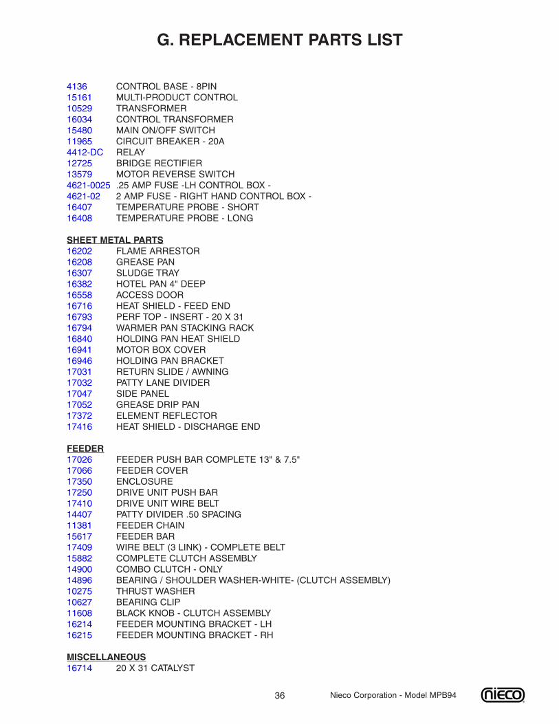
4136 CONTROL BASE - 8PIN15161 MULTI-PRODUCT CONTROL10529 TRANSFORMER16034 CONTROL TRANSFORMER15480 MAIN ON/OFF SWITCH11965 CIRCUIT BREAKER - 20A4412-DC RELAY12725 BRIDGE RECTIFIER13579 MOTOR REVERSE SWITCH4621-0025 .25 AMP FUSE -LH CONTROL BOX -4621-02 2 AMP FUSE - RIGHT HAND CONTROL BOX -16407 TEMPERATURE PROBE - SHORT16408 TEMPERATURE PROBE - LONG
SHEET METAL PARTS16202 FLAME ARRESTOR16208 GREASE PAN16307 SLUDGE TRAY16382 HOTEL PAN 4" DEEP16558 ACCESS DOOR16716 HEAT SHIELD - FEED END16793 PERF TOP - INSERT - 20 X 3116794 WARMER PAN STACKING RACK16840 HOLDING PAN HEAT SHIELD16941 MOTOR BOX COVER16946 HOLDING PAN BRACKET17031 RETURN SLIDE / AWNING17032 PATTY LANE DIVIDER17047 SIDE PANEL17052 GREASE DRIP PAN17372 ELEMENT REFLECTOR17416 HEAT SHIELD - DISCHARGE END
FEEDER17026 FEEDER PUSH BAR COMPLETE 13" & 7.5"17066 FEEDER COVER17350 ENCLOSURE17250 DRIVE UNIT PUSH BAR17410 DRIVE UNIT WIRE BELT14407 PATTY DIVIDER .50 SPACING11381 FEEDER CHAIN15617 FEEDER BAR17409 WIRE BELT (3 LINK) - COMPLETE BELT15882 COMPLETE CLUTCH ASSEMBLY14900 COMBO CLUTCH - ONLY14896 BEARING / SHOULDER WASHER-WHITE- (CLUTCH ASSEMBLY)10275 THRUST WASHER10627 BEARING CLIP11608 BLACK KNOB - CLUTCH ASSEMBLY16214 FEEDER MOUNTING BRACKET - LH16215 FEEDER MOUNTING BRACKET - RH
MISCELLANEOUS16714 20 X 31 CATALYST
G. REPLACEMENT PARTS LIST
37 Nieco Corporation - Model MPB94
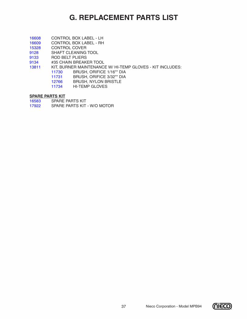
16608 CONTROL BOX LABEL - LH16609 CONTROL BOX LABEL - RH15328 CONTROL COVER9128 SHAFT CLEANING TOOL9133 ROD BELT PLIERS9134 #35 CHAIN BREAKER TOOL13811 KIT, BURNER MAINTENANCE W/ HI-TEMP GLOVES - KIT INCLUDES:
11730 BRUSH, ORIFICE 1/16"" DIA11731 BRUSH, ORIFICE 3/32"" DIA12766 BRUSH, NYLON BRISTLE11734 HI-TEMP GLOVES
SPARE PARTS KIT16583 SPARE PARTS KIT17922 SPARE PARTS KIT - W/O MOTOR
G. REPLACEMENT PARTS LIST
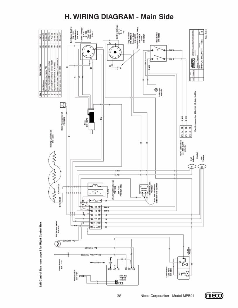
38
H.WIRING DIAGRAM - Main Side
Nieco Corporation - Model MPB94
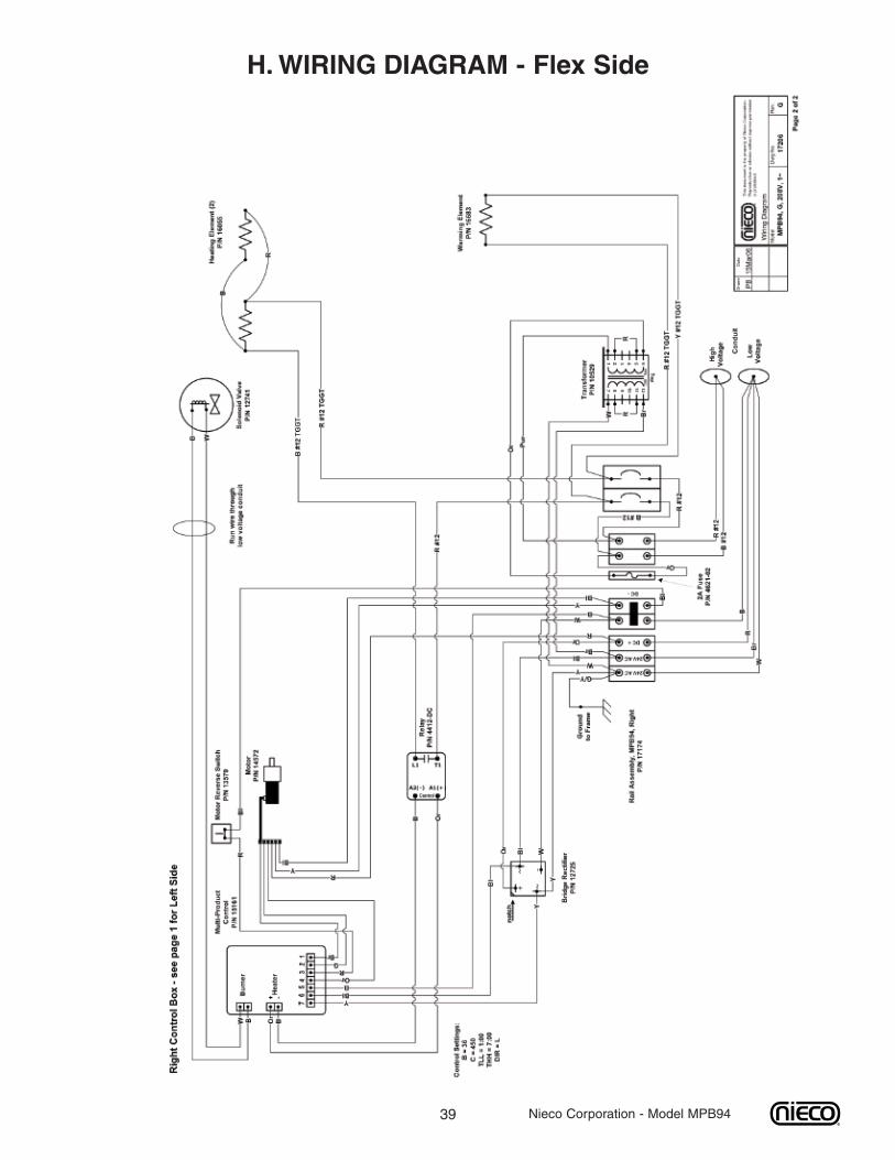
39 Nieco Corporation - Model MPB94
H.WIRING DIAGRAM - Flex Side
40
CAUTION
All electrical connections must bein accordance with local electricalcodes and any other applicablecodes.
CAUTION
Do not operate the broiler at gaspressures other than those statedhere. Doing so will affect the opera-tion of your broiler.
Nieco Corporation - Model MPB94
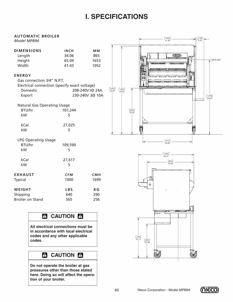
I. SPECIFICATIONS
AUTOMATIC BROILERModel MPB94
DIMENSIONS INCH MMLength 34.06 865Height 65.09 1653Width 41.43 1052
ENERGYGas connection 3/4” N.P.T.Electrical connection (specify exact voltage)Domestic 208-240V IØ 24AExport 230-240V 3Ø 10A
Natural Gas Operating UsageBTU/hr 107,244kW 5
kCal 27,025kW 5
LPG Operating UsageBTU/hr 109,590kW 5
kCal 27,617kW 5
EXHAUST CFM CMHTypical 1000 1699
WEIGHT LBS KGShipping 640 290Broiler on Stand 565 256
54.251378
33.58853
162563.9665.09
1653
BROIL BELT
1
41.431052
5.90150
35.82910
24.5862429.15
740
40.571030
34.06865
T
41 Nieco Corporation - Model MPB94
This warranty is effective for all Nieco Broilers shipped after November 1, 2005
Your new Nieco Automatic Broiler is guaranteed against original defects in manufacture of machine and compo-nent parts for one year. This one-year guarantee is subject to certain conditions and limitations as listed below.This warranty time begins when your machine is started up by your Nieco Distributor or authorized NiecoService Agent. If you do not receive a startup service, your warranty will begin either on the date you return theNieco warranty card that is shipped with your machine, or 30 days after shipment of the machine from the Niecofactory.
Generally, your guarantee provides replacement of all parts, which fail due to defects in manufacture for oneyear after startup of the machine. Parts which fail will be replaced by the Nieco distributor or Service Center inyour area who did the startup service. If the part is a customer installed component, the part will be sent you toreplace the defective part on your machine. If the part is one listed below, your Service Center will provide thelabor to replace it, subject to certain conditions. The parts that will be replaced are generally parts that requireservice level installation, calibration or adjustment. The parts that will be replaced are listed in appendix A. Theyare listed by broiler model.
If your broiler has a manufacturing defect that requires service labor to repair, those repairs will be performed byyour startup Nieco Service Center or Distributor. Those repairs will be performed subject to certain conditions asmentioned in the parts replacement section.
Nieco guarantees the correct mechanical operation of the equipment at the time of startup of the machine by anauthorized Nieco servicer. Nieco makes no warranty, expressed or implied of broiling effect or of exact capacityas subjective judgments, product variations and or customer caused machine conditions beyond Nieco’s abilityto predict or control may alter the broiling performance of the machine. Both Burger King Corporation and Niecohave extensively tested Nieco broilers prior to Burger King Corporations approval of Nieco broilers for BurgerKing products and restaurants.
Nieco specifically does not warrant or guarantee or provide compensation for any lost production, lost product,lost labor or lost sales or other consequential damages that may occur as a result of equipment malfunction orfailure. This disclaimer of liability for consequential damages applies whether the cause of malfunction or failureis otherwise covered by our warranty or not. In any event, Nieco’s liability shall be limited to replacement of theequipment or return of the equipment and refund of the original purchase price.
When you purchased your Nieco broiler, startup service was included in the purchase price if you are located ina territory covered by a Nieco Distributor or Service Center. This startup service is not delivery or installation orhookup. The startup service is to verify the correct mechanical operation and broiling performance of themachine, make any necessary adjustments and calibrations and provide answers to any machine questionsabout operations, cleaning, assembly or re-assembly. The startup service is not a training service. However,your servicer will provide all information that they can about the machine. The servicing Distributor or ServiceCenter will provide all warranty and after sales service and parts to you.
Validation of warranty is required by startup of your machine by an authorized Nieco Service Center orDistributor. This validation may be done directly with the factory if the startup is done by the customer or by anon-Nieco servicer. Nieco does not provide startup compensation to non-Nieco servicers. Nieco does valida-tion automatically on receipt of the startup report from your servicer. We strongly recommend you assure valida-tion by returning the warranty card shipped with the machine and register your machine for Nieco’s parts andservice due notification system. If an authorized Nieco servicer did not perform a startup, receipt of the warrantycard will validate the warranty. If a startup is not performed and submitted to the factory, the warranty period willstart 30 days from the date the machine was shipped from the factory.
This warranty is valid for North America and most other countries. Mandated warranties in some countries mayvary due to specific warranty laws, requirements or commercial practices or customs in these various countries.Check with the country Nieco Distributor for variations from this basic Nieco warranty.
J.WARRANTY INFORMATION
42 Nieco Corporation - Model MPB94
The Nieco warranty does not cover the following:
1. Ordinary wear and tear, deterioration or damage.2. Defects in parts or performance caused by improper cleaning, maintenance or adjustment.3. Adjustments and re-calibrations are not covered by warranty except when a part needing such isreplaced under warranty by a Nieco servicer.4. Misuse or improper cleaning or assembly of the broiler and its components.5. External causes of defective performance. This includes gas and electrical supply and hookup partsand all exhaust components and exhaust adjustment.6. Machines that have been improperly repaired by non-Nieco servicers.7. Machines with parts installed which Nieco does not approve or supply. Approved parts are availablefrom your Nieco Service Center, Distributor or otherwise authorized Nieco parts seller. No other partshave been tested or approved by Nieco or Burger King Corporation and no other parts have beenapproved as a component of the broiler by approval agencies including, NSF, CSA, CE, SVGW andAGA. Burger King Corporation patents certain parts. These patented components are available throughthe Nieco supply system.8. Burning components after six months of service. These burning components include gas burners ofall types, protective shields, reverberators, electric elements, pilot lights, thermocouples, or gasorifices of any type. Note however that this warranty does not apply to parts that are damaged ordestroyed due to normal service or improper or non-cleaning.
Warranty items, labor or parts, are available only from your Nieco Service Center or Distributor who started upyour machine unless other arrangements as described below are made with Nieco. Some parts suppliers, whilean authorized Nieco parts supplier, are not an authorized warranty center or warranty parts supplier.
Labor warranty is subject to these limitations:
1. Labor warranty work is to be performed during regular working hours. Off-hour labor may be subjectto additional charge by the servicer.2. One-hour travel in each direction to the restaurant from the servicer’s place of business is included.
Restaurants in more distant or remote locations may be charged additional travel time or overnight accommoda-tion, if necessary.
Your Nieco Service Center or Distributor will make warranty decisions. Nieco has provided our servicers withguidelines for warranty work and standards for repair time. If your Nieco servicer rejects your warranty claim,you are required to pay the servicer even though you dispute the charge. To dispute any warranty decision, firstcontact the Service Center or Distributor principals. If you are not satisfied, contact your Nieco RegionalManager or the Nieco Service Manager or any Nieco Customer Service administrator. Nieco will immediatelyinvestigate your claim and make a warranty decision. If you are still not satisfied, appeal your claim to RSI or BKSupply Management who will jointly investigate with Nieco management and make a final decision. If you havepaid your servicer and your claim is honored, your money will be refunded. You are responsible for paying theservicer when due, however, regardless of the status of any claim.
If you are supplied warranty parts without warranty labor, Nieco or your warranty parts supplier may require theparts to be returned to the factory as a condition of receiving the warranty parts. This is particularly true of highvalue important components as motors and controls, or any parts showing a pattern of failure. If required, Niecowill pay the return freight cost and give instructions via your servicer on how to return the parts. Warranty partswill be shipped by your Distributor or Service Center from their parts center by the least expensive means. If yourequire more immediate shipment, your service parts supplier may charge additional for this expedited freightservice.
If you have qualified maintenance employees or wish to use a qualified non-Nieco agency for warranty laborservice otherwise covered under this Nieco warranty, you or your servicer may apply to your Nieco RegionalManager for certification as an alternate Nieco servicer. Such servicer shall be solely responsible to the usingcustomer for all actions and liabilities. If the Nieco Regional Manager qualifies such servicer, Nieco will payscheduled warranty allowances to the customer for warranty work performed by these alternative servicers. Thispayment will not include any travel time. Nieco will provide this schedule and limitations when the servicer isqualified and accepted.
43 Nieco Corporation - Model MPB94
This warranty is valid for North America and most other countries. Mandated warranties in some countries mayvary due to specific warranty laws, requirements or commercial practices or customs in these various countries.Check with the country Nieco Distributor for variations from this basic Nieco warranty.
The parts schedules listed by models are those parts that are warranted by Nieco. If the part requires servicereplacement, your Nieco Servicer will do it, within the terms of this warranty. If your restaurant requires addition-al service or travel time, your Servicer will make an extra charge for those services or distances.
If the part is a user replacement part, you will be sent the part as described in this warranty. Your servicer willnot install it as part of their warranty service.
Nieco P/N Ignition and Gas System
2177 Regulator, RV47L, 1/2"2209-05 Combination Gas Valve 3/4, 24VDC10291 Hot Surface Igniter, 24V (Glow Plug)12741 Solenoid Valve, 24VAC 1/4" Compression Fitting16407 Thermocouple Probe, Short, 5.5"16408 Thermocouple Probe, Long, 11.63"16921 Ignition Module, 24V
Electric Elements
15691 Element, 220V, 950W16055 Element, 220V, 725W15650 Warmer Element, 220V, 900W
Drive Motor and Electrical Components
4412-DC Relay (input 3-32VDC, output 240V/25A)10529 Transformer, 240VAC input, 24VAC output11965 Holding Cabinet Circuit Breaker12725 Bridge Rectifier13579 Motor Reverse Switch13727 Speed Control Base13570-B Load Sensing Control Base14572 Brushless Motor15161 Multi-Product Speed Control15480 Main Switch, Panel Mount Rocker, 50 amp
Feeders
14900 Engagement Pin Assembly

Nieco Corporation7950 Cameron DriveWindsor, CA 95492(707) 284-7100 Office • (707) 284-7430 Faxwww.nieco.com • e-mail: [email protected] in the USA © 2005 Nieco CorporationReorder # 9999-99203