nia annual report 2016/17 - sp energy networks · nia distribution annual report 2016/17 page 7...
TRANSCRIPT

NIA Annual Report 2016/17
NIA Distribution Annual Report 2016/17
Page 2
SP Energy Networks (SPEN) is committed to delivering the Transmission Grid of the future through our licensed business SP Transmission (SPT).
This is our fourth Network Innovation Allowance (NIA) Annual Transmission Report and is an overview of on-going Transmission related projects being undertaken, and those initiated, during the regulatory year 2016/2017.
Following SPEN’s success of our Network Innovation Competition (NIC) Phoenix – System Security and Synchronous Compensators proposal in 2016 we are now looking to apply learning from relevant supporting NIA projects in the delivery of this NIC project. Our portfolio of NIC projects (VISOR, FITNESS and Phoenix), together with our portfolio of NIA projects gives us a globally leading position on transmission innovation.
A major focus of our innovation activity centres around black start and ensuring security of supply as the transmission network continues to become ever more dynamic. VISOR is revolutionising the real-time monitoring of the GB transmission system to provide GB-wide real-time visibility of dynamic behaviours, enhance resilience and increase energy efficiencies and capacities. The improved system visualisation will also help protect against catastrophic events that could result in a complete or partial blackout of the GB system. VISOR can also help restore the system in the event of a blackout.
Phoenix will provide the GB transmission system with an economical replacement for the stability and security of supply previously offered by large conventional synchronous generators. Phoenix does not only cover technology innovation but also commercial innovation. As part of Phoenix, we are collaborating closely with the Transmission System Operator. We will develop and demonstrate a commercial framework to financially incentivise the relevant ancillary services. The project will also make regulatory recommendations to enable future roll-out.
In response to Ofgem’s 2017 NIC, SPEN invited third parties, for the first time, to submit applications. These applications were requested to address the key challenges that our transmission network faces now, or will face in the future.
We continue to seek innovative opportunities to improve the way our network operates to provide continual benefits to our customers and to accommodate greater future penetrations of low carbon technologies.
Our innovation focus remains firmly centred on our customers and stakeholders, who shape both our Transmission Innovation Strategy and innovation project portfolio that could help toward the successful delivery of RIIO-T1. Given the challenges and opportunities facing our energy system this emphasises the need for a stable regulatory framework to fund effective and efficient innovation activities through RIIO-T2.
Similarly to our third party challenge for innovation ideas under NIC, SPEN welcomes third parties to submit innovative ideas for potential NIA projects.
Colin Taylor Director of Engineering Services
ForewordColin Taylor (Director of Engineering Services)

NIA Distribution Annual Report 2016/17
Page 3Contents
Foreword 2
Executive Summary 5
Part 1 – Introduction1 Introduction 6
Part 2 – Progress Summary2.1 NIA SPT 1303 IEC 61850 Integration of
Substation Protection and Control - Test Facility 8
2.1.1 NIA SPT 1303 Project Progress 9
2.2 NIA 1504 Managing Uncertainty in Future Load Related Investment 10
2.2.1 NIA SPT 1504 Project Progress 10
2.3 NIA 1505 Trial of Open Innovation in Utilities Sector 11
2.3.1 NIA SPT 1505 Project Progress 11
2.4 NIA 1506 Development of a Standard 33kV Damped Harmonic Filter Design 13
2.4.1 NIA SPT 1506 Project Progress 13
2.5 NIA 1507 Modelling of Static and Dynamic Loads 15
2.5.1 NIA SPT 1507 Project Progress 15
2.6 NIA SPT 1601 Power 2 Tower: Stage 1 17
2.6.1 NIA SPT 1601 Project Progress 17
2.7 NIA SPT 1602 UAV Platform Development for Automated Asset Condition Diagnosis 18
2.7.1 NIA SPT 1602 Project Progress 19
2.8 NIA SPT 1603 Trialling Long-Lasting Tower Paints 20
2.8.1 NIA SPT 1603 Project Progress 20
2.9 NIA SPT 1604 Introduction of Environmentally Friendly Alternatives to SF6 22
2.9.1 NIA SPT 1604 Project Progress 22
2.10 NIA SPT 1605 Cable Diagnostics for HVDC Cables 23
2.10.1 NIA SPT 1605 Project Progress 23
2.11 NIA SPT 1606 Reuse of Existing Concrete Assets 24
2.11.1 NIA SPT 1606 Project Progress 24
2.12 NIA SPT 1607 Non-Intrusive Assessment Techniques for Tower Foundations 25
2.12.1 NIA SPT 1607 Project Progress 25
2.13 NIA SPT 1608 Reducing Energy Losses from Transmission Substations 26
2.13.1 NIA SPT 1608 Project Progress 26
2.14 NIA SPT 1609 The Planning Data Exchange System between Network Licensees to Enable a Smarter Grid 27
2.14.1 NIA SPT 1609 Project Progress 27
2.15 NIA SPT 1610 Innovative Approach for Transmission Harmonic Issues 28
2.15.1 NIA SPT 1610 Project Progress 28
Part 3 – Collaborative NIA Projects Led By Other Transmission Companies3.1 NGET 0088 Transformer Research Consortium 29
3.1.1 NIA NGET0088 Project Progress 29
3.2 NIA NGET 0105 Enhanced Weather Modelling for Dynamic Line Ratings 30
3.2.1 NIA NGET 0105 Project Progress 30
Part 4 – NIA Activities Linked to SPT Innovation Strategy4 NIA Activities Linked to SPT Innovation Strategy 31
4.1.1 SPT NIA Project Mapping with Innovation Strategy 35
Part 5 – Areas of Significant New Learning 5.1 Project Learning: NIA SPT 1303 IEC 61850
Integration of Substation Protection and Control - Test Facility 36
5.2 Project Learning: NIA 1504 Managing Uncertainty in Future Load Related Investment 36
5.3 Project Learning: NIA 1505 Trial of Open Innovation in Utilities Sector 36
5.4 Project Learning: NIA 1506 Development of a Standard 33kV Damped Harmonic Filter Design 36
5.5 Project Learning: NIA 1507 Modelling of Static and Dynamic Loads 37
5.6 Project Learning: NIA SPT 1601 Power 2 Tower: Stage 1 37
5.7 Project Learning: NIA SPT 1602 UAV Platform Development for Automated Asset Condition
Diagnosis 37
5.8 Project Learning: NIA SPT 1603 Trialling Long-Lasting Tower Paints 38

NIA Distribution Annual Report 2016/17
Page 4Contents
5.9 Project Learning: NIA SPT 1604 Introduction of Environmentally Friendly Alternatives to SF6 38
5.10 Project Learning: NIA SPT 1605 Cable Diagnostics for HVDC Cables 38
5.11 Project Learning: NIA SPT 1606 Reuse of Existing Concrete Assets 38
5.12 Project Learning: NIA SPT 1607 Non-Intrusive Assessment Techniques for Tower Foundations 38
5.13 Project Learning: NIA SPT 1608 Reducing Energy Losses from Transmission Substations 39
5.14 Project Learning: NIA SPT 1609 The Planning Data Exchange System between Network Licensees to Enable a Smarter Grid 39
5.1 Project Learning: NIA SPT 1610 Innovative Approach for Transmission Harmonic Issues 39
5.2 Project Learning: NIA NGET 0088 Transformer Research Consortium 40
5.3 Project Learning: NIA NGET 0105 Enhanced Weather Modelling for Dynamic Line Ratings 40

NIA Distribution Annual Report 2016/17
Page 5
Our fourth Network Innovation Allowance (NIA) Annual Transmission Report has been compiled in accordance with Ofgem’s Electricity Network Innovation Allowance Governance Document which sets out the regulation, governance and administration of the Electricity NIA. This fourth NIA Annual Statement presents an overview of the projects we have initialised during the regulatory year 2016/2017 and an update on those projects reported during 2015/2016 which are still active.
The progress of each project aligns with the five innovation objectives set out in our Transmission Innovation Statement:
• Innovation meeting the needs of stakeholders;
• Innovation opportunities are identified in a timely manner, which will benefit these stakeholders;
• Innovation is managed in an efficient and proactive manner;
• A balanced portfolio of innovation is pursed which includes commercial, process and technology innovation; and
• The outcome of innovation activity is adopted by the wider business to ensure that customers benefit at the earliest opportunity whilst minimising the risk to the integrity of the network.
Our NIA innovation project portfolio will continue to be shaped by on-going stakeholder engagement, both internal and external, with a view to maintaining a balanced portfolio that will address not just the near/medium term transmission issues, during the current price control period (RIIO-T1), but also those anticipated as longer term requirements (beyond 2021).
In addition to funding smaller projects, we will continue to utilise NIA Transmission funding, where appropriate, to prepare for future Network Innovation Competition (NIC) submissions.
In addition, we will aim to maximise knowledge transfer with other licensees and facilitate useful outcomes into Business as Usual at the earliest opportunity.
Executive Summary

NIA Distribution Annual Report 2016/17
Page 6
SP Transmission has obligations to meet the Special Condition 3H (The Network Innovation Allowance) of the Electricity Transmission Licence, which was introduced as one of the key innovation proposals for the RIIO-T1 (Revenue = Incentives + Innovation + Outputs, 2013-2021) model for price control. The purpose of the NIA is to encourage Network Licensees to innovate to address issues associated with the development of their networks.
NIA is to provide a consistent level of funding to Network Licensees to allow them to carry out smaller innovative projects for two purposes:
• To fund smaller projects which meet the criteria set out in this Governance Document; and
• To fund the preparation of submissions to the Network Innovation Competition (NIC) which meet the criteria set out in the NIC Governance Document.
From that point of view, NIA plays an important and integrated role in uplifting the technology readiness levels (TRL), preparing for flagship demonstrations at national level and knowledge sharing.
It is acknowledged that the transmission network will experience unprecedented change in response to realising the low carbon ambitions for the UK. In order to meet the associated challenges innovative techniques, technologies and processes will be required to develop the transmission network. This is recognised by the fact that Innovation is a key element of the new RIIO - T1 model for price controls with the introduction of the NIA.
This report presents SPT’s NIA activities during the fourth year of its introduction, summarises progress made against objectives and highlights areas of significant new learning.
Developments in our transmission network over recent years have fundamentally been driven by an ongoing process of stakeholder engagement. SPT has identified a number of key themes as a result of our ongoing stakeholder engagement which are the principal drivers behind our innovation strategy.
Following a comprehensive stakeholder mapping activity, which formed part of our Transmission Innovation Strategy, the key outputs from subsequent stakeholder engagement to date have been:
Part 1 - Introduction
• Communicating with stakeholders to understand their needs and expectations more effectively;
• The connection of customers (demand and generation) onto the network to deliver sustainable low carbon energy through fair, clear and accessible processes;
• Maintain security of supplies and maximise long term value for end-users through improved network availability and reliability processes; and
• Minimise the environmental impact of our operations.
SPT recognise that consideration needs to be given to not only the RIIO-T1 period and stakeholder’s immediate needs, but also how we address the longer term issues which the transmission network may face. This is being addressed through a balanced portfolio of innovation projects where we are considering some of the longer term issues which may involve technology and techniques at a lower technology readiness level as well as immediate challenges to be faced over the next decade. This consideration is detailed within the report along with details of how our NIA activities link to SPT’s innovation strategy.

NIA Distribution Annual Report 2016/17
Page 7
During the reporting year 1st April 16 to 31st March 17 SP Transmission registered the following seven NIA projects:
1) NIA SPT 1604 Introduction of environmentally friendly alternatives to SF6
2) NIA SPT 1605 Cable diagnostics for HVDC cables
3) NIA SPT 1606 Reuse of existing concrete assets
4) NIA SPT 1607 Non-Intrusive Assessment Techniques for Tower Foundations
5) NIA SPT 1608 Reducing Energy Losses from Transmission Substations
6) NIA SPT 1609 The Planning Data Exchange System between Network Licensees to Enable a Smarter Grid
7) NIA SPT 1610 Innovative Approach for Transmission Harmonic Issues
The following sections provide a short overview of each active NIA project and summarises the progress that SPT has made on them. Further details on SP Energy Networks Innovation activities can be found on SPEN’s website (http://www.spenergynetworks.co.uk/pages/innovation.asp) and on the ENA Learning Portal (http://www.smarternetworks.org). Key learning associated with these projects is summarised in Part 5.
Part 2 - Progress Summary

NIA Distribution Annual Report 2016/17
Page 8
The IEC 61850 standard is intended to provide a standardised framework for the implementation of communication-based Substation Automation Systems (SAS). The principal benefits of employing the IEC 61850 approach are to achieve:
• Reduced engineering through re-usable designs
• Reduced time and cost for assembly and wiring
• Reduced site wiring and installation
• Increased off-line testing resulting in faster commissioning and reduced outage durations
Early experiences of attempting to engineer an IEC61850 compliant multi-vendor substation using the various files and software tools from each vendor led to unsatisfactory conclusions:
• It was difficult to achieve interoperability between devices from different vendors as each vendor has implemented the IEC 61850 standard according to its own designs. No two vendors implement the same functions to the same extent.
• The engineering process was complex and time consuming. It required extensive work to create the Intelligent Engineering Device (IED) configuration files and an expert knowledge of the underlying format of IEC 61850 configurations.
To further our knowledge experience and understanding of a GB compliant IEC 61850 process and related compliant IED’s, we intend to create an IEC 61850 test facility in Cambuslang that would not only create a "station bus" simulation substation but also allow the pilot of the new IEC 60870-101 communication protocol to our Operational Control Centre (OCC). This facility would provide the following benefits:
• Allow the testing of multiple IEC 61850 IED's from different vendors, remote terminal units (RTU’s) and fault recorders for compatibility and operational adequacy.
• Enable the risk free trial of the new IEC 60870-5-101 communication protocol and its support tools (the replacement of the existing Mk2A protocol).
• Allow the testing and programming of IED's before installation reducing outage time and streamlining work on site.
• Future proofing: if the IEC 61850 standard ever changes/progresses, this centre will be able to prove compatibility with future versions.
• Reduced support costs as SPEN would provide first line support for this system (i.e. reduced costly third party support).
The main project objectives area as follows:
• Prove the interoperability of all the IEDs and their performance in the SAS architecture proposed by SP Transmission.
• Prove communication between the test facility and the OCC using IEC 60870-5-101 (create a substation “Cambuslang”) and prove all required functionality from the OCC (including support tools).
• Thoroughly test compatibility of any new IED to be installed onto the network.
• Understand and document any issues faced and resolved from the above activities.
• Share all knowledge gained.
Part 2 - Progress Summary2.1 NIA SPT 1303 IEC 61850 Integration of Substation Protectionand Control - Test Facility

NIA Distribution Annual Report 2016/17
Page 9
2.1.1 NIA SPT 1303 Project Progress
Our objectives were:
1) Prove the interoperability of all the IEDs and their performance in the SAS architecture proposed by ScottishPower.
Progress: We have evaluated IED interoperability and have now installed the first IEC61850 132kV protection scheme solution at Windyhill substation. The substation is now live and on the system.
2) Prove communication between the test facility and the OCC using IEC 60870-5-101 (create a substation “Cambuslang”) and prove all required functionality from our Operational Control Centre OCC (including support tools).
Progress: We have proved that we can communicate with the OCC using the IEC 60870-5-101 protocol.
3) Thoroughly test compatibility of any new IED to be installed onto the network.
Progress: For our NIC FITNESS project, which will involve utilising new types of IED, we plan to evaluate these new devices in the test facility.
4) Understand and document any issues faced and resolved from the above four activities.
Progress: As we encounter issues we have recorded them and how they were resolved. As this scheme is completely new to us we have adopted an exceptionally cautious approach to testing IEDs. Protection testing is always thorough however when an issue has arisen and the resolution involved modifying relay configurations the IED has been completely retested. As confidence and understanding grows in the solution complete retesting may be deemed unnecessary.
5) Share all knowledge gained.
Progress: We have provided IEC61850 training and plan to roll out further training. The objective being to address knowledge shortfall and build a good IEC61850 understanding.
This project is now complete.
Part 2 - Progress Summary

NIA Distribution Annual Report 2016/17
Page 10
Uncertainty in relation to future demand and wind and PV generation output is already becoming a matter of concern in electricity network planning. Expected uptake of heat pumps, electric vehicles and other low-carbon technologies (LCT) will further increase uncertainty.
This project will develop and demonstrate (in prototype form) methods to use simulation techniques to examine a large range of ‘scenarios’ of future demand and generation development and output. This will be done by sampling from suitable statistical models of these and other external factors such as time-of-day and weather. The sampling approach will be designed to give a coherent picture of future network use, considering both traditional load and generation, and the uptake and behaviour of new technologies. The resulting scenarios will then be simulated and analysed individually to evaluate network performance metrics such as of power flows, constraint violations and reliability statistics. This large-scale sampling and analysis approach will result in a statistically representative database of network operating states and external conditions.
Methods to statistically interpret and interrogate this database will then be developed to identify the nature, location and factors underlying the most likely constraint violations and performance degradations, and to identify priority locations and trigger points (in terms of load growth, LCT uptake, etc.) for the deployment of interventions to solve anticipated problems.
The project analysis will focus on one grid supply point in the ScottishPower Transmission area.
2.2.1 NIA SPT 1504 Project Progress
Sampling methods to draw coherent time series of network operating points from historical records of electrical demand and selected low-carbon technology behavior have been created, and methods developed to modify these time series to reflect future changes in underlying demand and LCT deployment. These series have been used to develop a simulation infrastructure capable of efficiently analyzing the significant resulting body of sampled network states, and a corresponding database of network scenarios and results.
Models of smartgrid interventions which might be considered as alternatives to traditional network reinforcement have been developed and integration of these models with the simulation and analysis infrastructure has been demonstrated.
Part 2 - Progress Summary2.2 NIA 1504 Managing Uncertainty in Future Load RelatedInvestment
Appropriate consideration has been given to the design of straightforward interfaces and data structures to facilitate extension to represent new network technologies as they are identified as being of interest.
Work has commenced on methods to generate new representative time series of demand and LCT behavior based on statistical models of historical observations. These time series will take account of statistical relationships between geographically diverse locations of a technology and between different technologies and a common underlying influence such as weather conditions.

NIA Distribution Annual Report 2016/17
Page 11
The Open Innovation (OI) model is being developed to bring together the company challenges and the innovators. It has been shown that the most innovative and game-changing ideas can come from outside the sector. In addition, it can be time and resource challenging to develop and deliver suitable projects within the business.
Scottish Enterprise awarded SP Energy Networks with funded to promote contracts with Scottish SME’s by the implementation of Open Innovation. SP Energy Networks works together with Subsea 7, Weir and Doosan Babcock to share the advances done in Open Innovation inside each during the duration of the programme.
Open Innovation programme aims to evolve the concept of innovation in the companies working on this programme. Innovation usually means focus on inside research and development to develop new technologies or processes to create new products to improve the current market or to open new markets for the company.
Open innovation changes this paradigm, involving the acquisition, licensing and use of technologies developed outside the company to solve the challenges, as well as the spin-off of technologies developed inside the company that are not used or may have applications in a different industry.
Open Innovation programmes aims to increase the number of SMEs working together with SP Energy Networks to expand and spread the talent.
2.3.1 NIA SPT 1505 Project Progress
The project has focussed on the Stage 2 (18 months) – Delivery Phase, with a continual revision of the Planning and Approving work. This is the second progress report and covers the period of the Open Innovation programme delivery from April 2016 to March 2017, “the reporting period”.
The Project Delivery Team (PDT) has undertaken the following activities during this reporting period:
Study and search of related to Open Innovation programmes that could be implemented in SPEN.
As part of the Scottish Enterprise Cohort of companies, SPEN has been an active member both in sharing information on the direction for Open Innovation and learning how best to roll-out the model.
Search of specific partner for helping with the development of crowdsourced challenges. We have selected two partners, one to support and develop the Challenge creation process; and the second one is to take that challenge to the extended solver community. These are currently going through the approvals process.
Multiple workshops have taken place with a wide range of end users from operational to specific skill sets; these have been warmly received with a growing appetite for innovation. The frequency of these events has been at least one per quarter.
Hatch-A-challenge Process.
The internal Hatch-Challenge process steps and the internal infographic for information gathering.
Understand the use of internal communication tools, and improve their use. Our internal Yammer posts have kept the wider audience updated on the progress to date, sharing the experience but also identifying potential OI champions.
Prepare internal knowledge dissemination events for the employees of the company. This has been included in Learning Lunch Sessions.
Part 2 - Progress Summary2.3 NIA 1505 Trial of Open Innovation in Utilities Sector
Challenge request Publish Gather
Innovation tech board
Iop 3 Lauch outside
Review responses Trial BAU
Hatch a challenge

NIA Distribution Annual Report 2016/17
Page 12
SPEN’s stand at the Venturefest Scotland Event, which is a pathway for learning about Open Innovation, and how SPEN can work with the Solver Community. This is planned again for September 2017, where SPEN will run a panel workshop covering engagement with SME’s.
Venturefest Scotland – The SPEN Open Innovation Stand at the Glasgow Science Centre building.
Part 2 - Progress Summary2.3 NIA 1505 Trial of Open Innovation in Utilities Sector
The Open Innovation Programme has identified key challenges that are being addressed, but more importantly the knowledge obtained in the first year will provide the legacy foundations for increased staff engagement, more sharing of knowledge and a wider take up of SME’s who had untapped skill sets.

NIA Distribution Annual Report 2016/17
Page 13
SPEN evaluates the compliance of connection applications (Generator and Load) with respect to industry standards utilising Engineering Recommendations (ERs). A number of problems related to harmonic voltage compliance are frequently encountered by SPEN:
• An increasing number of power electronic converter driven generators are being connected via long cable circuits. This type of connection often leads to resonant conditions that result in amplification of existing background harmonic voltage distortion. This effect is often compounded by extensive windfarm cabling.
• At the time when a connection offer is made, not enough information is available about the cable circuit, the windfarm layout or the characteristics of future adjacent connections to make an assessment of the harmonic performance of the network.
• A large number of network outages, demand conditions and possible future network changes have to be considered when establishing mitigation measures. This makes design of suitable harmonic filters difficult, requiring extensive harmonic studies.
To deal with these issues, the feasibility of developing a standard harmonic filter design was investigated in this project. This project demonstrates whether it is possible to design a harmonic filter building block that can be widely deployed in different network conditions. It is recognised that such a standard filter design would not be optimal for each application. However, if successful, it is anticipated that the cost and efficiency penalties associated with a standard harmonic filter will be eliminated by the following advantages:
• Extensive filter design studies and measurement (or estimation) of background harmonics will not be required on a site by site basis. A standard filter design can easily be incorporated in transmission connection offer timescales.
• Harmonic filter requirements can be estimated early in a project, reducing the risk of noncompliance to SPEN and developers and hence eliminating business risks.
• The risks and confidentiality problems associated with analysing the harmonic performance of neighbouring or interacting connections are reduced.
Part 2 - Progress Summary2.4 NIA 1506 Development of a Standard 33kV Damped Harmonic Filter Design
The project will be carried out in two stages:
Stage I: the feasibility of a standard harmonic filter “building block” that can be deployed to mitigate increased harmonic voltages that are primarily due to amplification of background harmonics.
Stage II: If Stage I is successful, develop a detailed filter design and a component-level specification of the filter.
2.4.1 NIA SPT 1506 Project Progress
The project has progressed in Stage I and Stage II as planned and we aim to complete the project by May 2017 in line with the project registration. The following progress has been made:
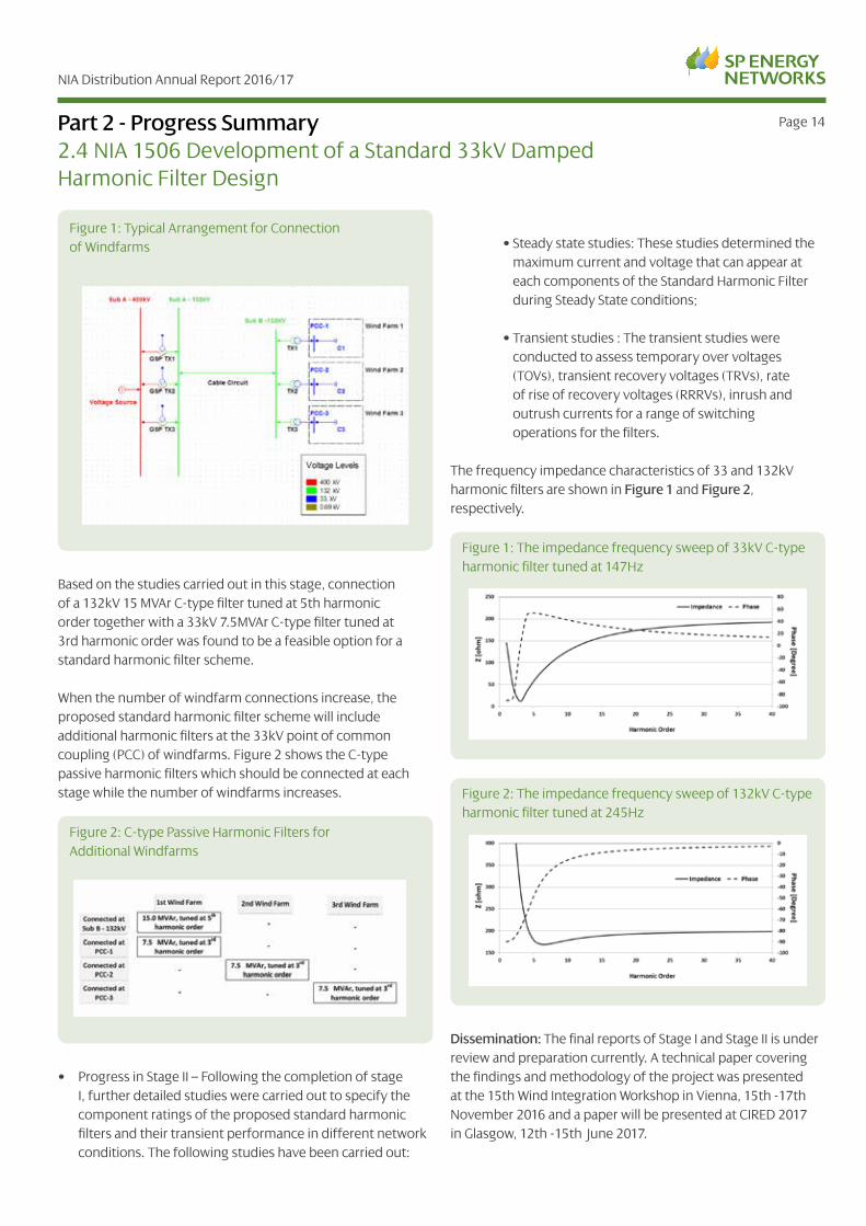
• Completion of Stage I – A methodology was developed in Stage I to identify a fit-for-purpose standard damped harmonic filter scheme for a network representing a typical arrangement for connection of windfarms, see Figure 1. The proposed methodology was applied on an extensive range of network scenarios and a standard harmonic filter scheme was proposed.
NIA Distribution Annual Report 2016/17
Page 14
Based on the studies carried out in this stage, connection of a 132kV 15 MVAr C-type filter tuned at 5th harmonic order together with a 33kV 7.5MVAr C-type filter tuned at 3rd harmonic order was found to be a feasible option for a standard harmonic filter scheme.
When the number of windfarm connections increase, the proposed standard harmonic filter scheme will include additional harmonic filters at the 33kV point of common coupling (PCC) of windfarms. Figure 2 shows the C-type passive harmonic filters which should be connected at each stage while the number of windfarms increases.
• Progress in Stage II – Following the completion of stage I, further detailed studies were carried out to specify the component ratings of the proposed standard harmonic filters and their transient performance in different network conditions. The following studies have been carried out:
Part 2 - Progress Summary2.4 NIA 1506 Development of a Standard 33kV Damped Harmonic Filter Design
• Steady state studies: These studies determined the maximum current and voltage that can appear at each components of the Standard Harmonic Filter during Steady State conditions;
• Transient studies : The transient studies were conducted to assess temporary over voltages (TOVs), transient recovery voltages (TRVs), rate of rise of recovery voltages (RRRVs), inrush and outrush currents for a range of switching operations for the filters.
The frequency impedance characteristics of 33 and 132kV harmonic filters are shown in Figure 1 and Figure 2, respectively.
Dissemination: The final reports of Stage I and Stage II is under review and preparation currently. A technical paper covering the findings and methodology of the project was presented at the 15th Wind Integration Workshop in Vienna, 15th -17th November 2016 and a paper will be presented at CIRED 2017 in Glasgow, 12th -15th June 2017.
Figure 1: Typical Arrangement for Connection of Windfarms
Figure 2: C-type Passive Harmonic Filters for Additional Windfarms
Figure 1: The impedance frequency sweep of 33kV C-type harmonic filter tuned at 147Hz
Figure 2: The impedance frequency sweep of 132kV C-type harmonic filter tuned at 245Hz

NIA Distribution Annual Report 2016/17
Page 15
The ultimate goal of this project is to improve the understanding of behaviour of load centres and evaluate the existing load models used in the system studies performed by SPEN. It is expected that by achieving this, the accuracy/effectiveness of network planning and operation tools will be improved by:
• gaining a better understanding of load behaviour
• improving understanding of existing load models
• creating new methods for the estimation of load model parameters
• demonstrating a methodology for estimation of load model parameters using different load models
• assessing the interaction between different load types and the main grid.
Accurate load models can support improved decision making when considering the required system expansion. It is expected that the exploitation of the existing assets can be improved, potentially deferring network reinforcement and influencing fundamental network design principles. Last but not least, a detailed understanding of demand behaviour is a prerequisite for integration of system operation actions at distribution and transmission levels.
In order for the project to deliver these benefits, the investigators from The University of Manchester are
Part 2 - Progress Summary2.5 NIA 1507 Modelling of Static and Dynamic Loads
proposing an approach for the estimation of the unknown load parameters of generic aggregated load models based on measurements recorded from the distribution/transmission system. This approach would first be demonstrated using detailed simulated studies in DIgSILENT PowerFactory. It is assumed that the research will also include processing of laboratory data records, which will be used to validate the quality of conclusions obtained through simulation studies.
2.5.1 NIA SPT 1507 Project Progress
The work planned for this project has been undertaken as planned. First, an assessment about an optimal architecture of a flexible data acquisition and processing platform (short platform), capable of estimating dynamic load model parameters based on real substation data, has been undertaken. The aspects of the speed of data acquisition and the reliability of communication channels are investigated, too. The role of the abovementioned platform is to concentrate Phasor Measurement Units (PMU) data from the network in an existing Phasor Data Concentrator (OpenPDC). To allow a fast data concentration and further processing the existing OpenPDC has been modified, so that a smooth data transfer from the data concentrator to the processing and visualisation units was achieved. This has enabled further development of new applications needed for advanced characterisation of load behaviour.
As a result of the assessment of optimal platform architecture, the solution presented in Figure 5 below has proposed.
Figure 5 Optimal Platform Architecture
Matlab
Router
Sensor (PMU)
Substation
Disturbance files
GIgSILENT
Visualization
VPN server
Event detection
PDC
Virtual PMU
Disturbance Database
Load modeling
Java EE7 application

NIA Distribution Annual Report 2016/17
Page 16
As it can be observed from the above Figure, the connection between PMUs and the PDC is established over a VPN connection (VPN Server in Figure above). This has been achieved using a proxy router. After the data reaches the PDC building block, connection with the Java EE7 application is established over fast access data buffers. The Java EE7 application runs the event detection algorithm on the phasor measurements received by the PDC. If a relevant disturbance (here a voltage drop) is detected, then the corresponding measurement samples are saved within a disturbance database, depicted as the green hexagonal block in Figure. Simultaneously and in a separate execution thread, the load model parameter estimation algorithm developed in Year 1 of the project is triggered, with the detected disturbance as its input. Two of the most important data channels within the Java EE7 application are represented by Matlab generated synthetic signals and dynamic power system simulations within DIgSILENT. It is expected that these two data sources will be extensively used during platform testing. As it can be observed, next to the visualisation application, two major applications, a) Event detection and b) Load Modelling, i.e. estimation of unknown load model parameters, are developed.
The above platform developed is now ready for processing realistic data, as well as for its customisation to achieve optimal outcome for its users.
Part 2 - Progress Summary

NIA Distribution Annual Report 2016/17
Page 17
There are many requirements for monitoring along the length of, or at specific points on, overhead lines – examples include dynamic line rating, partial discharge measurement on tower based cable sealing ends and fault location. However, the provision of 230 Vac single phase supplies to individual towers to power the monitoring equipment is problematic and unlikely to yield economically viable solutions. This collaboration with Elimpus is the first of a proposed three stage development of a monitoring system that can be used along the length of a transmission line, comprising of towermounted, wirelessly communicating monitoring platforms which are powered by energy harvesting from the immediate environs of the transmission tower.
The monitoring system solution would be such that measurements made from one tower can be wirelessly transmitted to the next tower and so on until the data reaches an access point, such as a substation or a fibre optic cable joint. Hence, the tower-mounted hardware (TMH) units will have three functions:
1) Power management
2) Local monitoring
3) Store and forward node for adjacent TMH units comprising the system.
This project is based on the following design assumptions:
• The tower mounted hardware will be non-invasive, not requiring any outage for installation.
• The TMH unit will be bolted to the tower steel-work and will be lightweight to facilitate rapid deployment.
• The TMH design will be based on commercially available, power-efficient components that will be designed for operation under all weather conditions commonly encountered on OHL routes.
• TMH unit design life-expectancy > 10 years.
• No periodic maintenance of the TMH units will be required.
• The data output of the monitoring system will be compatible with SP’s business systems.
2.6.1 NIA SPT 1601 Project Progress
The electrical methodology for the energy harvesting has been designed and successfully prototyped on the bench. The next stage is to mount these options on to the site pylon towers. These units will be monitored by a remote battery powered unit that will record the energy levels collected over several weeks. This will provide the initial result for the feasibility in an energy source based on the 3 options.
The physical arrangements of the energy harvesting sensors have been discussed with Scottish Power and the designs will be updated to fit the pylon towers selected for use.
Part 2 - Progress Summary2.6 NIA SPT 1601 Power 2 Tower: Stage 1

NIA Distribution Annual Report 2016/17
Page 18
Unmanned Aerial Vehicles (UAVs) technology is developing rapidly and is already being use by some Transmission Network Operators for overhead lines inspections. With a decreasing deployment cost and the possibility of incorporating relevant sensors which meet the weight restrictions for drone carriage and are cost effective, UAVs are becoming an alternative to current inspection process.
Inspections carried out by UAVs will be able to access components and areas not accessible by helicopters, reduce the number of crews sent to inspect areas of difficult access, and reduce the personnel climbing towers for taking a closer look at the components. Eventually, this will lead to a reduction of the inspection and maintenance cost, as well as the reduction of the risk, risk of failure and risk associate to personnel climbing the transmission towers.
The project focuses on the selection and deployment of innovative sensors on UAVs to improve diagnosis within the inspection process, and on the capture and initial processing of data coming from those sensors. Although a number of UAVs are equipped with different sensor technology, at present there is no bespoke solution available for overhead lines and transmission towers surveys designed for the purpose of automatic diagnostic of the degradation of their components. Research at the Power Networks Demonstration Centre (PNDC) and University of Strathclyde has already been undertaken in this area, and will set the basis for the development of the automatic diagnostic capability of the UAV.
The project constitutes a first step towards a Business As Usual (BAU) solution where UAVs will be able diagnose a number of problems and broadcast information in real time during the inspection process of overhead lines.
Part 2 - Progress Summary2.7 NIA SPT 1602 UAV Platform Development for Automated Asset Condition Diagnosis

NIA Distribution Annual Report 2016/17
Page 19Part 2 - Progress Summary
2.7.1 NIA SPT 1602 Project Progress
This project is now complete
The project was divided in the following stages, as described below:
1) Procurement stage:
Sensors suitability evaluated and weight/power requirements considered in the creation of a platform rig which can be attached to and powered by the SME (EagleiSystems) UAV.
During this stage an RGB and a thermal camera to be deployed on a commercially available drone were selected. The identified sensors met UAV weight restrictions, and provided high resolution images. The selected sensors were,
• Visual sensor Matrix Vision BlueCougar 10 Megapixel GigE connectivity
• Thermal sensor Xenics GOBI uncooled Long-wave Infrared (LWIR) sensor - GigE connectivity
2) Sensor testing: Laboratory testing of sensor system as a whole.
During this stage the integration at hardware level of visual and thermal imaging, and development of an analysis algorithm which can run in real-time on the drone hardware platform was carried out. A storage solution to keep relevant data and archive it so that it is easily identifiable and searchable after an inspection run was developed.
3) Evaluation of drone upgrade:
During this stage the power connections were set up, and enclosure for the sensors was, and a field tests was carried out.
4) Energised field trials at the Power Networks Demonstration Centre (PNDC):
A few tests were performed at PNDC network with the aim of identifying potential issues when operating UAVs near high voltage lines. No major issues were found.
5) De-energised field trials at Scottish Power Energy Networks (SPEN) Transmission sites:
Two trials at Dealain House and Carruthmuir respectively took placed. The aim was to evaluate the performance in observing difficult-to-access components like insulators and feedthroughs .
6) Energised field trial at SPEN Transmission sites:
A test at Carruthmuir overhead line was carried out to evaluate the performance in observing difficult-to-access components like insulators and feedthroughs and issues when operating UAVs near high voltage lines.
7) Evaluation of the information captured by the UAV:
This stage focused in comparing acquired data against information captured by current inspections at SPEN.
8) Project Report: Detailed project findings delivered and suggestions for future phases.
The final report of the project has been delivered.
9) Project Dissemination Meeting.
A meeting has taken placed to disseminate the findings of the project.

NIA Distribution Annual Report 2016/17
Page 20Part 2 - Progress Summary2.8 NIA SPT 1603 Trialling Long-Lasting Tower Paints
SPEN’s transmission towers require to be painted on an on-going basis to protect the steelwork from adverse environmental impact. For non-corroded steelwork, a two coat paint system or, on occasion, a single coat paint system is applied. The current policy of once every 12 years is based on known paint technology at the time of implementing the policy. The formulation being used has been essentially fixed for a good number of years and there are now a range of coatings available which purport to be able to provide 25 years or more of protection.
Before these could be applied or any potential change to coating practice made, it is necessary to evaluate their performance against the needs of the industry and with relevance to the surface preparation achievable in practice and typical application environment.
It is recognised that significant financial and system access benefits could be realised through the modification of the current policy to longer painting cycles based upon the application of a more enduring paint treatment and consequently SPEN is seeking longer-life alternatives.
This project will test a range of candidate coating systems to identify which are suitable for application to UK electricity pylons, what the repainting interval should be for these new coatings and what the relative cost of adoption would be.
An evaluation report will rate the performance of each coating system as regards the practical and laboratory tests carried out. It will assess the costs of each coating system relative to the
control (present-specification coating) by conducting a life-cycle assessment and rate each coating on metrics to include ease of application. Finally, it will recommend the coating system best meeting the requirements and whether any additional work is necessary before wide-scale adoption.
2.8.1 NIA SPT 1603 Project Progress
The scope of this project is to undertake laboratory tests and practical trial applications of six proposed new coatings on a sample of pylons, sufficient to measure the suitability and performance of the coatings in this UK application. Additional testing will also be carried out such that successful coatings can be adopted quickly into Business as Usual application.
Stage 1 Completed
Engage with the coating suppliers to ensure that each coating is applied to the samples according to the recommended instructions.
A trial circuit for the practical paint application on 14 towers has been identified in the Manweb area.
Stage 2 Specify Laboratory Tests and Practical Tests
Laboratory tests to estimate longevity and supplementary tests if necessary to meet ‘Electricity Company Approved’ status have been undertaken.

NIA Distribution Annual Report 2016/17
Page 21Part 2 - Progress Summary
Manufacturer Coating layer Product name 1-pack / 2-pack
Coating type
Jotun Paints (Europe) Ltd
Base Jotamastic Smartpack 2 Surface tolerant, high solids, high build amine cured epoxy mastic coating.Intermediate Jotamastic Smartpack 2
Top Jotamastic 87 GF 2Polyamine cured epoxy mastic coating reinforced with glass flakes.
Chugoki Paints B.V.
Base Epscon Zinc HB-2 2Combination of metallic zinc, epoxy resin and hardener.
Intermediate Thermo Shadan Primer 2 Water-based polyamide curing epoxy primer.
Top Thermo Shadan 1 Water-based fluorine resin.
MCDuff ZingaBase Zinga/Zingasolv 5% 2
Cold-applied liquid galvanising.Top Zinga/Zingasolv 5% 2
Induron Proctective Coatings
BaseInduramastic (H-1217 and Q-1217)
2 Surface tolerant high build epoxy.
TopInduramastic (H-8107 and Q4-8107)
2 High build surface tolerant aluminium filled epoxy.
3MBase Skotchkate MCU 125 1 Moisture-cured polyurethane aluminium.
Top Skotchkate UV 662 1 Moisture-triggered polyurethane.
Spencer Coatings Ltd (Trail)
Base Bondon 115 EG601/702 2 High build epoxy containing aluminium.
Top Bondon 112 EE600/702 2 High build epoxy containing MIO Pigment.
Spencer Coatings Ltd (Control)
Base YP644 1 Urethane alkyd resin with non-texic pigments, fillers zinc phosphate and MIO.
Top YF149 1 Urethane alkyd pigment with MIO.

NIA Distribution Annual Report 2016/17
Page 22Part 2 - Progress Summary2.9 NIA SPT 1604 Introduction of Environmentally Friendly Alternatives to SF6
SP Transmission Limited (SPT) have implemented a project to reinforce the 400kV and 275kV substations at Kilmarnock South to facilitate the planned amount of renewable generation capacity contracted to be connected to the transmission system in South West Scotland. A new 400kV double busbar Gas Insulated Substation (GIS) will be provided and built with a footprint designed to accommodate a total of 15 bays with an initial provision of 3 bays equipped with 400kV GIS switchgear. The employment of GIS offers benefits over AIS such as reduced space requirements (10% of AIS at 400kV) high reliability, improved safety, long service, reduced maintenance requirements, and low life cycle costs.
The main disadvantage of GIS is the use of large quantities of SF6. SF6 is an excellent insulator, and is widely used in the electrical industry in high-voltage air or gas insulated switchgear, but it is a greenhouse gas with an extremely significant impact on global warming. It is one of the six gasses listed in the 1997 Kyoto Protocol designed to lower greenhouse gas emissions worldwide.
As part of the RIIO T1 Business Plan, SPT aspires to identify measures to improve overall business carbon footprint where appropriate. SPT manage their SF6 inventory in accordance with industry good practice, but until recently, there was no alternative to SF6 that featured equivalent switching and voltage-withstand capabilities.
A number of companies are looking to develop environmentally friendly SF6 alternatives. GE Grid Solutions are one company who is leading this field and can now offer a revolutionary SF6-free solution, g3 which has been jointly developed with 3MTM, a leader in environmentally sustainable solutions. g3 has 98% less impact on global warming than SF6. With performances comparable to SF6, it is a suitable technology for the development of today’s new generation of clean high voltage equipment. GE Grid Solutions has been contracted to install the new 400kV GIS switchgear including a Gas Insulated Busbar (GIB) at Kilmarnock South and has confirmed that one 400kV (GIB) can be installed with g3 as part of an innovation pilot.
2.9.1 NIA SPT 1604 Project Progress
SPEN have placed orders with GE to supply one section of 400kV GIB to be filled with g3 gas as a green replacement for SF6. This will reduce the total amount of SF6 gas used at site from 9.8 tonnes to 7.7 tonnes corresponding to a saving of approximately 46,000 tonnes of CO2.
Work has started on site to build the GIS installation and the GIS switchgear is expected to be delivered to site in early 2018.

NIA Distribution Annual Report 2016/17
Page 23Part 2 - Progress Summary2.10 NIA SPT 1605 Cable Diagnostics for HVDC Cables
The application of HVDC cables over long distances is on the increase and it is becoming clear that the ageing characteristics of the insulation in such cables are not well understood. As this is a project to obtain better understanding, the method is one of understanding what is currently known about the ageing characteristics and then to consider what else needs to be done to address the knowledge gap. From the gaps in the knowledge identified through the review, a systematic and logical experimental work plan will be developed to understand partial discharges in HVDC cable systems. The work plan will be based on laboratory experimentation as well as computer simulation (where appropriate) to allow a better understanding of how partial discharges are generated in a HVDC cable system and the mechanism responsible.
The new knowledge generated from this research will inform subsequent innovation activities that are expected to lead to improved asset management techniques with benefits including the following: -
• Asset replacement before failure.
• Reduced number of faults.
• Targeted investment on cables that are in greatest need of replacement.
2.10.1 NIA SPT 1605 Project Progress
A 6-month interim review was conducted by Strathclyde university and a short report was submitted. The scope of research was modified from partial discharge detection of HVDC cables to the electric field grading material used for cable insulation and accessories.
In order to realise a nonlinear resistive stress control, some researchers had added microrvaristors into polymer. From that, it was decided to focus research on nanocomposites doped insulation materials used for HVDC cables.

NIA Distribution Annual Report 2016/17
Page 24Part 2 - Progress Summary2.11 NIA SPT 1606 Reuse of Existing Concrete Assets
There is a very large asset base of concrete structures within ScottishPower that are approaching or have potentially reached the end of their service life. Current practice within ScottishPower is to demolish these concrete structures and replace them with new steel structures.
It has been identified that alternative methods are available that can possibly extend the lifespan of the existing structures. Where it is identified within the concept design that certain existing structures can be reused then ScottishPower want to investigate the viability of this. To realise the potential benefit of this, ScottishPower wants to review current practice and identify a methodology that is more sustainable, requires less outage time to construct and is more economical.
The aim of this project is to create an assessment process and specification to determine whether these existing concrete assets are suitable for reuse. This project will develop a methodology to determine the assessment criteria, reuse, strengthening and repair process. The methodology will then be used to implement the recommendations from the design assessment which will be collated through the design reporting stage. This will allow recommendations to be implemented within each asset replacement programme to allow existing concrete assets to be re-furbished as appropriate. It is anticipated that this approach will allow ScottishPower and the wider industry to achieve cost and time savings on major construction projects which in turn will provide increased network resilience by reducing outage requirements. The reuse of these structures will also support ScottishPower's sustainable development policy.
2.11.1 NIA SPT 1606 Project Progress
The draft methodology report is being finalised. An issue regarding the data quality for the assessment process, which was not foreseen, has arisen (see Part 5.11 on Project Learning). This has led to an additional section being added to the report which will consider the risk that this adds.
The sites have been identified for testing and data for these sites has been collected ready for the assessment stage.

NIA Distribution Annual Report 2016/17
Page 25Part 2 - Progress Summary2.12 NIA SPT 1607 Non-Intrusive Assessment Techniques for Tower Foundations
The tower structures that make up the transmission overhead line network can be extended with good maintenance and strategic replacement of steelwork. Will it is easy to observe and identify the corrosion level of the steelwork on a lattice tower evaluating the condition of the steelwork and concrete where buried is very difficult. The current approach for evaluating the condition of existing tower foundations involves excavating around the foundations so they can be visually inspected. This excavation increases the complexity, cost and environmental impact of the inspection. The foundations are subject to targeted assessment during, or before major works; every tension and angle tower is assessed as well as a sample 20% of suspension tower foundations. Due to the intensive labour and time effort involved, it is normal practice to intrusively inspect only a sample of towers.
This project will measure the suitability and performance of two non-intrusive approaches, vibration and ground penetrating radar, both separately and in combination in determining the condition of buried tower structures.
The scope of this project is to undertake laboratory tests and practical trial applications on a sample of transmission towers to provide validation and quantification of the potential benefits of the techniques under consideration.
2.12.1 NIA SPT 1607 Project Progress
The V route is a 132kV overhead line double circuit line which runs between Galashiels, Hawick, and Gretna/Harker. This line is being modernised as part of RIIO-T1 and was identified as a suitable site for this project as the BaU work included ground investigation and intrusive foundation works to determine the condition of the existing foundations. A 132kV line was chosen to maximise project benefits as any learning would be transferrable to SPM. The V Route survey works are ongoing at the time of writing this update.
Prior to the commencement of surveys, research was undertaken to identify a suitable Ground Penetrating Radar (GPR) device. A range of products are available on the market, each of which has its respective advantages and disadvantages. A suitable ground penetrating radar for Non- Intrusive Assessment Techniques for Tower Foundations requires the following:
• Ability to penetrate depths of three to four meters
• As fine a resolution as possible to detect irregularities in foundations
• Rugged and able to be used on off-road and difficult terrain
• Weather resistant
A number of devices were researched and tested, with a view to sourcing a unit that best filled the project’s criteria. In order to achieve reasonable penetrating depths, a low radar frequency was required. However, fine resolution requires a high radar frequency. As GPRs need to be designed to meet safe operating requirements, there is no scope to increase the power of high frequency signals to remove this trade off. A number of GPRs either increase signal bandwidth or include two transmitters operating at different frequencies to counter this trade-off. The latter option was found to be preferable in this scenario as it allows for the detection of deeper buried foundations, while more shallow foundations can be interpreted in greater resolution. A GPR unit was sourced that is waterproof, suitable for difficult ground conditions and also capable of transmitting two frequencies.

NIA Distribution Annual Report 2016/17
Page 26Part 2 - Progress Summary2.13 NIA SPT 1608 Reducing Energy Losses from Transmission Substations
At present, substation energy consumption is uncontrolled and unmonitored. Energy is consumed for a number of processes (e.g. heating, battery charging or dehumidifying) to ensure network resilience and ensure the security of the electricity network. Typically, the supply for Grid substations comes from the secondary windings on 33kV neutral earthing transformers, and is unmetered. As such, substation demand is not monitored or accounted for while it contributes to the SPEN transmission losses.
This project will initially aim to establish, through audits and metering, the baseline level of energy usage of a number of trial substations in the SP Transmission licence area, and then use the collected data to model the performance of the substation buildings. These data models will allow opportunities for energy efficiency to be identified, then enable the development for a plan for substation energy efficiency.
2.13.1 NIA SPT 1608 Project Progress
The scope of works and the Collaboration Agreement with Edinburgh Napier University has been finalised.

NIA Distribution Annual Report 2016/17
Page 27Part 2 - Progress Summary2.14 NIA SPT 1609 The Planning Data Exchange System betweenNetwork Licensees to Enable a Smarter Grid
DNOs and National Grid have a long track record of successful interaction in operational planning and investment planning coordination. However, the expected uptake of low carbon technologies and the advent of the Smart Grid will impact on the required level of interaction between the DNO and the System Operator (SO) in the future.
Greater interaction will be necessary as distributed energy resources (DER) become increasingly required to provide not just energy but whole-system services as well. For example, embedded generation, demand response and energy storage, along with distribution system services can contribute to system balancing. To achieve this, “full coordination across the SO/DSO boundary” will be required.
Presently, operational and planning information is transferred between the DNOs and SO in accordance with Grid Code requirements. For example, DNOs provide “Week 24” network planning data to National Grid annually and in return, National Grid supplies “Week 42” data, which is a network-equivalent data model for fault level assessments.
The “Week 24 Authorised Network Model” is an official snapshot in time of the distribution network and sets the baseline for all subsequent data exchange. This model includes all the detailed network data, including topology, connectivity, electrical parameters, and all embedded generation up to 1MW. It also contains the long-term (i.e. >12 months) demand and generation forecasts.
The existing method of information collection and submission between the DNO and SO is highly dependent on key personnel extracting data from a number of different systems manually. Furthermore, the analysis of the data is undertaken in uniform manner without taking into account the characteristics of the DNO region. This process is not sustainable when the requirement for more frequent transfers of a richer set of information is taken into consideration.
A holistic approach is required to clarify the existing and future roles of DNO, TO and SO in an involving (but also changing at accelerated pace) energy sector. This project is aiming to provide a tool to facilitate such a transition.
2.14.1 NIA SPT 1609 Project Progress
Discussions are on-going with the GB System Operator (SO) and Distribution Licensees regarding the project scope.

NIA Distribution Annual Report 2016/17
Page 28Part 2 - Progress Summary2.15 NIA SPT 1610 Innovative Approach for Transmission Harmonic Issues
This is the second stage of a project looking at harmonic filters on the transmission network. This follows on from a feasibility study (NIA_SPT_1506) which looked at the optimisation of the location and size of harmonic filters across a section of the network in a coordinated manner. Harmonic Filtering has been previously looked after by individual developers, and this project will make a good contribution so that customers can made reduced investment to safeguard the quality and standards of electricity supply.
SPEN is currently developing an extensive network in South West Scotland for the connection of a number of windfarms. The harmonic performance of this network has to be evaluated with the aim of:
1) Developing a coordinated, efficient and cost-effective harmonic filtering solution.
2) Setting harmonic emission limits for each windfarm.
3) Substantially reducing the risk of harmonic non-compliance for both SPEN and windfarm developers.
The extensive use of cables in the transmission and windfarm networks indicates a risk of lower order harmonic resonances in the network. It is expected that the high resulting voltage gain factors will dictate the installation of a number of harmonic filters, even if the background harmonics in the existing network are within acceptable limits and the harmonic emissions from the windfarms are low. An optimised harmonic filtering solution may require installation of filters on the transmission network and/or the windfarm connection points.
2.15.1 NIA SPT 1610 Project Progress
The SPEN PowerFactory network model including the cable, transformers, overhead lines and lumped MV windfarm collector network models were analysed to ascertain the suitability for the harmonics studies to be carried out as part of the project. The proposed network to 2025/26 is very complex, so detailed optimization of the number and types of contingencies to be studied was carried out. All the nodes in the network were assessed to optimize the most relevant 275 kV, 132 kV, 33 kV and 11 kV nodes to be monitored as part of the harmonics studies. Additionally, a verification process and high level analysis of the 275 kV background harmonics supplied by SPEN for use in the harmonics studies was carried out.

NIA Distribution Annual Report 2016/17
Page 29Part 3 - Collaborative NIA Projects Led By Other Transmission Companies 3.1 NGET 0088 Transformer Research Consortium
This project was started in April 2013 and is scheduled to last four and a half years. This research project being undertaken by the University of Manchester builds on initial work undertaken assessing ester based alternatives to conventional insulating oil and seeks to enhance understanding of transformer health and the key variables that can lead to premature failure. The research focuses on ageing indicators, partial discharge diagnostic, dissolved gas and thermal analysis.
While this project is being undertaken at laboratory scale consideration is being given to system application issues. The outcome of this project is expected to inform asset management policies with the aim of optimising operational and capital expenditure.
It is believed that the work packages will provide outcomes that can realistically be deployed in short to medium term timescales that will allow SPEN asset managers to benefit from new test methods and data collection techniques that will directly contribute towards the transformer asset decision making. This development of transformer specifications that include online monitoring and condition data collection techniques that reduce maintenance costs and provide more accurate condition assessment information.
The ongoing research into alternative fluids should give the required confidence for the deployment of these fluids at higher voltage levels. This will provide network operators with a solution that has environmental and fire safety attributes that traditional mineral oil does not have.
3.1.1 NIA NGET0088 Project Progress
This project has been registered as a joint project by National Grid (NIA_NGET0088), and therefore they will provide a progress summary in their NIA Annual Report 16/17 consequently; no project progress has been included in this report. However, we, as an active partner of the project, will outline our New Learning for this project in Part 5.

NIA Distribution Annual Report 2016/17
Page 30Part 3 - Collaborative NIA Projects Led By Other Transmission Companies 3.2 NIA NGET 0105 Enhanced Weather Modelling for Dynamic Line Ratings
Dynamic Line Rating (DLR) schemes have the potential to release significant network headroom on circuits supplying renewable generation that can be controlled by Active Network Management (ANM) schemes. Whilst the same DLR uplifts are present on the network’s main interconnector circuits, the headroom cannot be as readily exploited as there is less correlation between the required power transfer capacity and the ambient conditions under which significant uplifts can be achieved; nor is there a single controllable load to be coupled with an ANM scheme to avoid excursions on the network. As a result of this, the exploitation of DLRs on the main interconnector circuits will be reliant on Control Engineers to manage the network loads and keep them in line with the available DLR uplift. However, to effectively do this without risking excursions on the network the Control Engineers will need to have confidence that the DLR will be available for a prolonged period of time, and this depends on accurate forecasting of dynamic ratings. At present the main focus of DLR schemes developed has been on the generation of an instantaneous value as opposed to a forecasted value several hours into the future.
This project makes use of an advanced spatial/temporal model developed within the Electronic and Electrical Engineering Department at Strathclyde University, and supported by SPT. In the enhancement of the methods for forecasting of dynamic ratings, Strathclyde University will use the available weather data from existing meteorological stations and hourly meteorological data from other sites across the UK to which Strathclyde University has access. The forecasting will be applied to the estimation of wind speed and directions in the vicinity of key overhead line spans for the purpose of calculating dynamic overhead line ratings. The model will also be applied to air temperature forecasting as it is the combination of wind speed and air temperature that determines overhead line cooling and subsequent maximum current carrying capacity.
The success criteria is the application of spatial interpolation techniques to determine forecasts at regular intervals along an overhead line and the use of wind speed, wind direction and air temperature forecasting to determine local overhead line cooling rates.
Other success criteria will be the provision of an estimate of uncertainty associated with the forecast so that the system operator can make appropriate judgements with respect to management of risk and the necessity for preventive actions.
3.2.1 NIA NGET 0105 Project Progress
This project has been registered as a joint project by National Grid, and therefore they will provide a progress summary in their NIA Annual Report 16/17 consequently; no project progress has been included in this report. However, we, as an active partner of the project, will outline our New Learning for this project in Part 5.

NIA Distribution Annual Report 2016/17
Page 31Part 4 - NIA Activities Linked to SPT Innovation Strategy
It is recognised that innovation cannot be a prescribed by rigid process but must stimulate creativity and new ideas. However, to ensure good governance, SPT has applied an over-arching framework to ensure that it is managed efficiently and delivers the benefits without constraining creativity.
The five innovation objectives within SPT are:
1. Innovation meeting the needs of stakeholders;
2. Innovation opportunities are identified in a timely manner, which will benefit these stakeholders;
3. Innovation is managed in an efficient and proactive manner;
4. A balanced portfolio of innovation is pursed which includes commercial, process and technology innovation. Our activity has a relevant focus on developments at different technology and commercial readiness levels to which balances radical with incremental innovation; and
5. The outcome of innovation activity is adopted by the wider business to ensure that customers benefit at the earliest opportunity whilst minimising the risk to the integrity of the network.
Figure 6 outlines the general R&D management structure within SPT.

NIA Distribution Annual Report 2016/17
Page 32Part 4 - NIA Activities Linked to SPT Innovation Strategy
As part of our long term innovation strategy, stakeholder engagement will be central to ensuring that our innovation plans are meeting customer’s expectations. The involvement of stakeholders is also a vital source of ideas for innovation –
particularly the academic community, equipment suppliers and other network operators (DNOs and TOs).
Figure 7 illustrates the NIA development process at SPT.
NIA Distribution Annual Report 2016/17
Page 33Part 4 - NIA Activities Linked to SPT Innovation Strategy
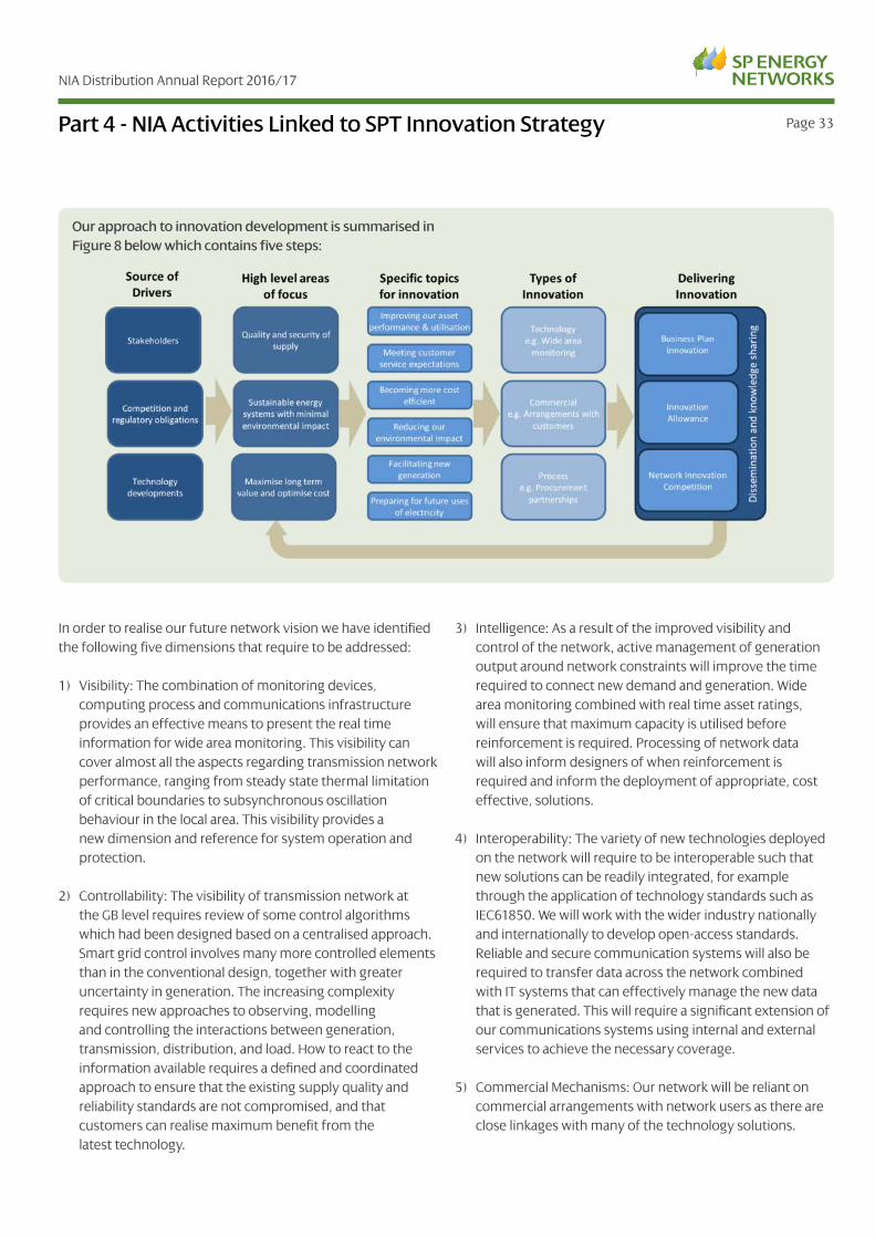
Our approach to innovation development is summarised in Figure 8 below which contains five steps:
In order to realise our future network vision we have identified the following five dimensions that require to be addressed:
1) Visibility: The combination of monitoring devices, computing process and communications infrastructure provides an effective means to present the real time information for wide area monitoring. This visibility can cover almost all the aspects regarding transmission network performance, ranging from steady state thermal limitation of critical boundaries to subsynchronous oscillation behaviour in the local area. This visibility provides a new dimension and reference for system operation and protection.
2) Controllability: The visibility of transmission network at the GB level requires review of some control algorithms which had been designed based on a centralised approach. Smart grid control involves many more controlled elements than in the conventional design, together with greater uncertainty in generation. The increasing complexity requires new approaches to observing, modelling and controlling the interactions between generation, transmission, distribution, and load. How to react to the information available requires a defined and coordinated approach to ensure that the existing supply quality and reliability standards are not compromised, and that customers can realise maximum benefit from the latest technology.
3) Intelligence: As a result of the improved visibility and control of the network, active management of generation output around network constraints will improve the time required to connect new demand and generation. Wide area monitoring combined with real time asset ratings, will ensure that maximum capacity is utilised before reinforcement is required. Processing of network data will also inform designers of when reinforcement is required and inform the deployment of appropriate, cost effective, solutions.
4) Interoperability: The variety of new technologies deployed on the network will require to be interoperable such that new solutions can be readily integrated, for example through the application of technology standards such as IEC61850. We will work with the wider industry nationally and internationally to develop open-access standards. Reliable and secure communication systems will also be required to transfer data across the network combined with IT systems that can effectively manage the new data that is generated. This will require a significant extension of our communications systems using internal and external services to achieve the necessary coverage.
5) Commercial Mechanisms: Our network will be reliant on commercial arrangements with network users as there are close linkages with many of the technology solutions.
NIA Distribution Annual Report 2016/17
Page 34Part 4 - NIA Activities Linked to SPT Innovation Strategy
To achieve these five dimensions, we consider three different ways in which we invest in the network. These investments can be described as follows:
Enablers: This includes smart-ready asset replacement and other investments which create a robust foundation and enabler for the smart grid applications. These are considered as “no regrets” investments which can be deployed in a top-down manner and are an essential component of the network. Having the enabling technology in place will allow us to flex between different future scenarios. Typical enablers are Remote Terminal Units for SCADA with expansion capability and the installation of additional network monitoring.
Applications: This is the implementation of a solution which has an immediate application to directly address an output within RIIO-T1 such as meeting load growth, facilitating new customer connections or improving quality of service. Where we have proposed a smart application, a cost benefit analysis (CBA) will be undertaken as in most cases a comparison with a traditional solution can be made. Typical applications are real time thermal ratings, intelligent voltage control or active network management.
Future Proofing: Where a positive business case exists, we will identify where additional enabling technologies are considered to be of long term benefit to customers, although not necessarily required in the short term. This category is also regarded as top-down investment as it is required to further enable other applications in the longer term. Future proofing investments are also subject to a CBA to ensure that they are efficient investments for the customer. Typical future proofing includes oversizing conductors for future load requirements and switchgear being pre-wired for sensors and automation.
The variety of new technology and commercial arrangements deployed on the network are vital to meeting the future requirements of our customers in a responsive and cost-effective way. However, it will be through the effective management and stewardship of the existing asset base that we will ensure value for money and that a sustainable network solution is delivered.

NIA Distribution Annual Report 2016/17
Page 35Part 4 - NIA Activities Linked to SPT Innovation Strategy4.1 SPT NIA Project Mapping with Innovation Strategy
Network InvestmentFigure 7 Nia project mapped to
SPT innovation strategy
Specific dimension
Enabler Application Future proofing Visibility Controllability Intelligence InteroperabilityCommercial mechanism
NIA 1303: IEC61850 Integration of substation protection and control:
test facility
NIA 1504:Managing uncertainty in future load
related investment
NIA 1505: Trial of open innovation in utilities sector
NIA 1506: Development of a standard 33kV damped
harmonic filter design
NIA 1507: modelling of static and dynamic loads
NIA 1601: Power 2 tower: stage 1
NIA 1602: UAV platform development for automated
asset condition diagnosis
NIA 1603: Trailing long-lasting tower paints
NIA SPT 1604: Introduction of environmentally friendly
alternative to SF6
NIA SPT 1605: Cable diagnostics for HVDC cables
NIA SPT 1606: Reuse of existing concrete assets
Nia SPT 1607: Non-intructive assessment techniques for
tower foundations
NIA SPT 1608: Reducing energy losses from
transmission substations
NIA SPT 1609: The planning data exchange system between
network licences to enable a smarter grid
NIA SPT 1610: Innovative approach for transmission
harmonic issues
NIA NGET 0105: Transformer research consortium
NIA NGET 0105: Enhanced weather modelling for
dynamic line rating

NIA Distribution Annual Report 2016/17
Page 36
The following identifies area of learning on a project by project basis:
5.1 Project Learning: NIA SPT 1303 IEC 61850 Integration of Substation Protection and Control - Test Facility
We have installed an IEC61850 protection and control scheme solution at Windyhill 132kV substation. The substation is now on the system. The test facility proved its worth when we discovered we had to upgrade firmware in GE IEDs due to a robooting issue, which was a cause for concern. We proved that the firmware upgrade resolved the issue and we also proved that the settings remained unaltered post firmware upgrade. Proving the firmware upgrade on site would be extremely difficult as the substation is live and on the system. We were able to prove that the firmware upgrade had no effect the IEDs and settings by extensive testing in the lab. We hope to reduce on site testing time on future projects by performing tests in the lab on new IEDs. The NIC FITNESS project will be a full 275kV IEC61850 ghost system. We propose to use the test facility to prove the interoperability etc. of the new IEDs associated with our FITNESS project.
5.2 Project Learning: NIA 1504 Managing Uncertainty in Future Load Related Investment
Methods for the statistical representation of LCT behavior – by decomposing the complex overall behavior into a series of relatively simple models which describe behavior at different timescales – appear to show promise for the generation of new representative time series to represent future behavior, or behavior at different locations in a network.
5.3 Project Learning: NIA 1505 Trial of Open Innovation in Utilities Sector
A learning point is that each business area should have the freedom to determine what is the most suitable solution rather than a one size fits all; and also that time taken to determine the scope and the business requirement is crucial.
Challenge generation: - with a need to focus on technology scouting to determine what has gone before and what can be developed
Time taken for business change in the disruptive phase should not be underestimated, as organisations have been run on a “Lean” structure with limited headroom for Innovation deployment.
The collective innovation strategy should be companywide and encompass the strategy and direction of the Company.
5.4 Project Learning: NIA 1506 Development of a Standard 33kV Damped Harmonic Filter Design
Based on the studies carried out, the areas of new learning and recommendations are as follows:
• The desktop studies showed that application of a damped standard harmonic filter for connection of multiple windfarms through a typical radial arrangement is feasible.
• The sensitivity analysis on the proposed standard harmonic filter scheme showed that larger background permissible voltage distortions in the 5th and 7th harmonic orders can be accommodated by the standard harmonic scheme if the capacity (MVAr) of the proposed 132kV harmonic filter increases.
• In addition to a surge arrester connected at the harmonic filter terminal, our lightening impulse studies showed that a surge arrester needs to be connected across a parallel resistor in the harmonic filter to bring the transient over voltages to within the permissible limits.
• Following the successful completion of Stage I and Stage II of this project, further work can be recommended as follows:
1) Re-evaluate the performance of standard harmonic filter when the harmonic emission injection from windfarms is considered;
2) Engage with potential suppliers to refine any design required and also determine the possible costs of manufacturing of the standard harmonic filters based on the component ratings determined in Stage II;
3) Manufactured, test and install the standard harmonic filter on one of the sites and monitor the performance of the filter pre-installation and post installation for a period of time. That will allow any refinement to the design if required.
Part 5 - Areas of Significant New Learning

NIA Distribution Annual Report 2016/17
Page 37
5.5 Project Learning: NIA 1507 Modelling of Static and Dynamic Loads
Key learning points are provided below:
• Different architecture for collection of PMU data can be used. The proposed architecture, called “flexible data acquisition and processing platform” offers a broad range of opportunities and through its flexible design options for using both real-time PMU data streams from actual substations, as well as from Matlab/DiGSILENT environment, through dynamic simulation of a power system
• The well-known OpenPDC, used world-wide as a Phasor Data Concentrator, has limitations which do not allow it to be used for real-time data visualization, posing a need for its modification.
• A new OpenPDC, obtained through modifications of its functionality enables real-time data visualization and creation of new Wide Area Monitoring, Protection and Control (WAMPAC) applications.
• Integration of data obtained from OpenPDC through a real-time platform compatible to the Java EE7 enterprise standards offers a full flexibility and easy integration of WAMPAC applications.
• Developed applications a) Event detection and b) Estimation of unknown load model parameters integrated into the platform perform as expected using Matlab obtained signals.
• A need for creation of communication channels to real-time operated PMUs installed in actual substations will open new opportunities and mechanisms for obtaining the information about behavior of load centers in Scottish Power.
5.6 Project Learning: NIA SPT 1601 Power 2 Tower: Stage 1
Initial scoping studies identified three main technologies (electric field, Aeolian vibration and earth wire current) as potential energy sources on a transmission tower.
Installation work for the three main options has highlighted a possible problem for the electric field option. ScottishPower
Transmission operations have raised safety concerns when fitting this sensor, and have insisted that it can only happen on a de-energised line. The vibration and current options are allowable on an energized line. Alternative sites may be needed for the electric field option.
5.7 Project Learning: NIA SPT 1602 UAV Platform Development for Automated Asset Condition Diagnosis
The project has identified commercial sensors that meet UAV weight restrictions and the standards for providing high resolution images of overhead line components. The sensor system comprising the RGB and the thermal camera as well as storage solution, is lightweight and fits to pre-existing UAVs with minimal modifications.
The images coming from both sensors can be combined in an open source development framework which allows future development and upgradeability without vendor lock in. Additionally, edge detection and hot-spot detection has been achieved. Furthermore, Wi-Fi transmission of these processed images for diagnosis, with annotated video recording of the images, demonstrate a unique capability which can augment the current inspection processes.
A major objective of the field trials was to establish if an UAV is stable and safely controllable near high-voltage transmission lines, and both live trials at Carruthmuir indicated that this is definitely possible, when the UAV flight controller is programmed to ignore any magnetometer measurement distortion and rely on GPS readings. The cameras and computer functioned well at a distance of 5 metres from 400 kV live conductors, therefore the platform can be declared to have met the main development objectives to show that the inspection route is viable and further development is potentially useful.
Finally, the project has investigated not only thermal and RGB cameras but also other sensors that could be deployed on the UAV at a later stage, such as UV and hyperspectral cameras.
Part 5 - Areas of Significant New Learning

NIA Distribution Annual Report 2016/17
Page 38
5.8 Project Learning: NIA SPT 1603 Trialling Long-Lasting Tower Paints
The scope for development was increased as it became clear that there was a strong business case for additional testing to ensure that the actual tests produce results that can be measured and of benefit to the DNO standards.
The scope for parameters to test is relatively wide, for example the location of the Towers, Salt level in the local atmosphere; the type of construction of the Tower; the method of application of the paint coats; the ease of mixing on site. A decision was made to limit the number of parameters to enable a direct comparison to be made.
This project looked at paint that was already in the market from suppliers; there is a case for working with paint developers for paints that have not reached the open market.
Paint application technology can develop faster than the paint coatings; which means that costs and time for the application phase could, potentially, be reduced.
5.9 Project Learning: NIA SPT 1604 Introduction of Environmentally Friendly Alternatives to SF6
The project at Kilmarnock South 400kV has allowed SPEN to understand the practical challenges of using alternative gases in a GIS installation. This has included:
• Determination of the correct Personal Protective Equipment to be utilised when handing new g3
• Appropriate same handling and safety rules that are required to be applied in case of arced g3 gas.
• Use of gas sensors and on-line continuous gas monitoring equipment for g3 gas
• Correct tools and instruments for checking gas leaks and routine measurement of gas quality
• Use of different filling device compared to SF6 in order to ensure a correct filling of the GIB
5.10 Project Learning: NIA SPT 1605 Cable Diagnostics for HVDC Cables
The chemistry department at Strathclyde University is to produce nanocomposite thin films in their laboratory. The insulation materials will be PE and PP. XLPE is widely used for both HVAC and HVDC cables at present and PP is a potential insulation for cable which has higher melting temperature and can be easily recycled. If PP can provide a better or just equivalent electrical performance, then PP could be used to replace XLPE in the future. Further adding nanoparticles into the insulation material, the space charge can be suppressed, which is considered as the main hazard for HVDC cables.
5.11 Project Learning: NIA SPT 1606 Reuse of Existing Concrete Assets
The project is still in the initial development of the methodology stage and the majority of learning is expected to appear towards the end of the project. However during consultation with Mott MacDonald an issue that came up was the collection of data for the assessment stage. Over time the site records and structure drawings have been transferred to microfilm. This has reduced the quality of the drawings of the structures making it difficult to see the overall dimensions and in particular the reinforcement details. Whilst collecting site data it has been found that quality of data has been varied with some sites providing better quality information than others. With gaps in the information this increases the risk as assumptions may need to be made which could lead to wrong conclusions being drawn. To mitigate this risk a risk matrix will be introduced to account for gaps in on-site data which will provide a decision tree approach for a person to consider when deciding the approach to take.
5.12 Project Learning: NIA SPT 1607 Non-Intrusive Assessment Techniques for Tower Foundations
Survey works have resulted in numerous alterations to the predicted methodology in order to adapt to ground and weather conditions. The presence of heavy wind and rain required changes to the mapping out of vibration measurements on the tower legs, while penetration depth and detection capabilities are affected by saturated soil. Furthermore, ground conditions at times required a change to the GPR grid scanning methodology. The modelling of vibration techniques through operating deflection shapes analysis and finite element analysis and the examination of GPR
Part 5 - Areas of Significant New Learning

NIA Distribution Annual Report 2016/17
Page 39
data will commence following the completion of survey works. The results of the project will then be compared with the BaU outcomes of the intrusive foundation works.
Stakeholder engagement has identified potential additional benefits from this project as the technology could be deployed to detect water ingress between the steel work and concrete of a foundation.
5.13 Project Learning: NIA SPT 1608 Reducing Energy Losses from Transmission Substations
There is no learning to report at this early stage of the project.
5.14 Project Learning: NIA SPT 1609 The Planning Data Exchange System between Network Licensees to Enable a Smarter Grid
There is no learning to report at this early stage of the project.
5.1 Project Learning: NIA SPT 1610 Innovative Approach for Transmission Harmonic Issues
An assessment was made on the impact of using lumped parameter models instead of more detailed windfarm MV collector networks. This involved some initial screening studies and comparisons between the frequency dependent impedance characteristics of both approaches to the MV model.
Some software script in Digsilent PowerFactory’s proprietary language (dpl) was written to automatically run harmonics studies and simulations under various contingencies and system conditions. This software will be used as the basis for the main analysis in the project.
Following optimization of the contingencies in the 2025/2026 cases; the network elements that had the biggest impact on harmonic distortion on the network were identified, and the reasons why were studied and verified against expectations.
Part 5 - Areas of Significant New Learning
Need image

NIA Distribution Annual Report 2016/17
Page 40
5.2 Project Learning: NIA NGET 0088 Transformer Research Consortium
Please refer to National Grid Electricity Transmission’s NIA Annual Report 16/17 for any details of areas of significant new learning on this collaboration project.
5.3 Project Learning: NIA NGET 0105 Enhanced Weather Modelling for Dynamic Line Ratings
Please refer to National Grid’s NIA Annual Report 16/17 for details of areas of any significant new learning on this collaboration project.
At the start of the project, the network licensees and their project partner were not aware of any established methods for forecasting of Dynamic Line Ratings (DLR). The development of a forecasting method was therefore the main aim, and has been achieved, not just on terms of a ‘point’ forecast but a probabilistic forecast that allows a system operator to take a conservative approach by choosing a value with a low probability of the actual rating being lower than it. However, the method has been demonstrated mathematically but only for a 30 minute forecast horizon. This still promises to provide value but not as much as over longer time horizons. Further work would be required to develop and test that. One particular challenge in doing so is that, under quite low wind conditions, the rating is highly sensitive to small variations in wind speed meaning that, with a conservative rating policy, the DLR is unlikely to give much enhancement over the static rating when using forecasts over longer time horizons. On the other hand, the static rating itself is not without risk.
Part 5 - Areas of Significant New Learning