nexus communicator 2.0 log database structure table names 6.1.3 remarks 6.1.4 fields definitions ......
TRANSCRIPT

Nexus Communicator 2.0
Log Database Structure
Revision 1.20 October 18, 2001
Doc # E107-7-10-120
e
Electro Industries/GaugeTech
1800 Shames Drive Westbury, New York 11590
Tel: 516-334-0870 Fax: 516-338-4741 Email: [email protected] Website: www.electroind.com
"The World Leader in Power Monitoring"
e Electro Industries/GaugeTech Doc # E107-7-10-120
Nexus Communicator Log Database Structure Revision 1.20 Published by: Electro Industries/GaugeTech 1800 Shames Drive Westbury, NY 11590 All rights reserved. No part of this publication may be reproduced or transmitted in any form or by any means, electronic or mechanical, including photocopying, recording, or information storage or retrieval systems or any future forms of duplication, for any purpose other than the purchaser’s use, without the expressed written permission of Electro Industries/GaugeTech. © 2001 Electro Industries/GaugeTech Printed in the United States of America.

e Electro Industries/GaugeTech Doc # E107-7-10-120
Customer Service and Support Customer support is available 9:00 am to 4:30 pm, eastern standard time, Monday through Friday. Please have the model, serial number and a detailed problem description available. If the problem concerns a particular reading, please have all meter readings available. When returning any merchandise to EIG, a return authorization number is required. For customer or technical assistance, repair or calibration, phone 516-334-0870 or fax 516-338-4741. Product Warranty Electro Industries/GaugeTech warrants all products to be free from defects in material and workmanship for a period of four years from the date of shipment. During the warranty period, we will, at our option, either repair or replace any product that proves to be defective. To exercise this warranty, fax or call our customer-service department. You will receive prompt assistance and return instructions. Send the instrument, transportation prepaid, to EIG at 1800 Shames Drive, Westbury, NY 11590. Repairs will be made and the instrument will be returned. Limitation of Warranty This warranty does not apply to defects resulting from unauthorized modification, misuse, or use for any reason other than electrical power monitoring. OUR PRODUCTS ARE NOT TO BE USED FOR PRIMARY OVER-CURRENT PROTECTION. ANY PROTECTION FEATURE IN OUR PRODUCTS IS TO BE USED FOR ALARM OR SECONDARY PROTECTION ONLY. THIS WARRANTY IS IN LIEU OF ALL OTHER WARRANTIES, EXPRESSED OR IMPLIED, INCLUDING ANY IMPLIED WARRANTY OF MERCHANTABILITY OR FITNESS FOR A PARTICULAR PURPOSE. ELECTRO INDUSTRIES/GAUGETECH SHALL NOT BE LIABLE FOR ANY INDIRECT, SPECIAL OR CONSEQUENTIAL DAMAGES ARISING FROM ANY AUTHORIZED OR UNAUTHORIZED USE OF ANY ELECTRO INDUSTRIES/GAUGETECH PRODUCT. LIABILITY SHALL BE LIMITED TO THE ORIGINAL COST OF THE PRODUCT SOLD. Statement of Calibration Our instruments are inspected and tested in accordance with specifications published by Electro Industries/GaugeTech. The accuracy and a calibration of our instruments are traceable to the National Institute of Standards and Technology through equipment that is calibrated at planned intervals by comparison to certified standards. Disclaimer The information presented in this publication has been carefully checked for reliability; however, no responsibility is assumed for inaccuracies. The information contained in this document is subject to change without notice.

Electro Industries/GaugeTech Doc #: E107-7-10-120 1
TABLE OF CONTENTS 1.0 Introduction 1 2.0 Database files 1
2.1 EIGData.DB 2.1.1 (Meter Name).DB
2.2 EIGNameList.DB 2.3 LogViewTempQuery.DB
2.3.1 yyyy_mm_dd_hh_nn_ss.TempQuery
3.0 Log database overview 2
3.1 Data entry process 3.2 Data display process
4.0 Data entry process 2 5.0 Data retrieve process 3
5.1 Data retrieve using Log Viewer program
5.2 General procedures on how to retrieve log data out of the database file
6.0 Database definitions 7
6.1 EIGData.DB 6.1.1 Tables overview 6.1.2 Table names 6.1.3 Remarks 6.1.4 Fields definitions
6.2 EIGNameList.DB 6.2.1 Tables overview 6.2.2 Tables 6.2.3 Remarks 6.2.4 How to obtain the data point text label from a data ID 6.2.5 Fields definitions
6.3 LogViewTempQuery.DB 6.3.1 Tables overview 6.3.2 Tables 6.3.3 Fields definitions

Electro Industries/GaugeTech Doc #: E107-7-10-120 2
Figures Figure 1 Data Entry Process
Figure 2 Data Display Process Figure 3 Data Process for EIGData.DB Figure 4 Data Process for LogViewTempQuery.DB Figure 5 EIGData.DBTables Figure 6 EIGNameList.DB Figure 7 LogViewTempQuery.DB
Appendices Appendix A EIGData.DB Fields Definition Appendix B EIGNameList.DB Fields Definition Appendix C LogViewTempQuery.DB Fields Definition Appendix D EIGData.DB Fields Relationships
Electro Industries/GaugeTech Doc #: E107-7-10-120 1
1.0 Introduction
The purpose of this document is to describe the structure of the databases used to store data by the Nexus Communicator software package. The database structures described below are templates, which contain characteristics of devices to be polled, and the types of data available. One database template file (EIGData.DB) is used to create a database per device in which all the historical data is stored. By default, this database uses the meter name as its file name to identify its origin. Although this paper is intended to describe how to access data from the meter database, it also contains a description of the Log Converter and Log Viewer programs and their associated databases. The Log Converter is used to translate the actual downloaded binary data into the database file for the Log Viewer to display. It should be noted that the database is not specific to any individual device. To add a new device, the appropriate entries for that device (data type, protocol, etc.) should be added to the EIGNameList.DB file. A driver program can then be written to download and translate data from the new device into the standard database format for reviewing. Current parameters for Electro Industries’ Nexus device are defined.
2.0 Database files
There are three database files for the software package. All are in the Microsoft Access 97 format. Their file extensions are DB.
2.1 EIGData.DB
Location: \[Windows system folder]. For Win95/98, it is in \System. For NT4, it is in \System32.
Description: This is the template database file to be duplicated for each device to store its data (converted from binary data format into this database format by Log Converter program).
2.1.1 (Meter Name).DB Location (default): \Electro Industries\Nexus Communicator\Retrieved Logs Description: This is the duplicated database for each device to store its logged data where
(Meter Name) is the designated meter name for that device.
2.2 EIGNameList.DB
Location: \[Windows system folder]. For Win95/98, it is in \System. For NT4, it is in \System32.
Description: This database serves as a lookup file for the Log Converter and the Log Viewer programs. It has the readings’ text names and unique IDs for each device’s reading property, data type definitions and more.

Electro Industries/GaugeTech Doc #: E107-7-10-120 2
2.3 LogViewTempQuery.DB
Location: \Electro Industries\LogViewer\Resource Description: This is the template database file for the Log Viewer program. It's duplicated
every time the Log Viewer program starts. Its structure is similar to the EIGData.DB file.
2.3.1 yyyy_mm_dd_hh_nn_ss.TempQuery Location: \Electro Industries\LogViewer\TempQuery Description: This is the run time version of the LogViewTempQuery.DB file. It is generated
every time the Log Viewer program starts. This file name is constructed with the year, month, date, hour, minute and second values. It stores the temporary query data generated by the Log Viewer program.
3.0 Log database overview
3.1 Data entry process
Before the data stored in the device can be presented to the end user, it must be downloaded, converted to readable values and stored in the database. Figure_1 shows that process using the Nexus Communicator software package.
3.2 Data display process
The data stored in the database can be presented to the end user for analysis. Figure_2 shows that process using the Nexus Communicator software package.
4.0 Data entry process
All Nexus devices must be assigned a unique device name before any logs can be downloaded. A binary *.nbl file is generated after the Nexus Communicator downloads any log from the Nexus device. If the device has a name such as UserA_Meter1, the file name will be automatically assigned as UserA_Meter1.nbl. If the device does not have a name, the Nexus Communicator software will ask the user to enter a file name.
If the download is successful, Nexus Communicator will make a back up copy of the binary file with the name in this format: file name – yyyy_mm_dd_hh_mm_ss.nbl. This back up file has a read only file attribute and is generated for debugging purpose only.
The Log Converter program is automatically started by Nexus Communicator immediately after a successful download. The Log Converter program is given the command to convert the downloaded binary file into a database format.
During the conversion process, two database files are needed.
1) EIGNameList.DB 2) EIGData.DB The first database serves as a data point lookup table. From the downloaded log file, we can obtain each data’s pointer and index number. From the DeviceProtocol_y_z table for the corresponding device and protocol, we can obtain each data point’s global unique ID and its property such as data type, PTCT ratio and full-scale value. All this information will be supplied to the converter program to calculate the final primary number for each data point.

Electro Industries/GaugeTech Doc #: E107-7-10-120 3
The second database is the device data template file. If the converter program did not find a device database file in the designated path for that device, a new device database file will be generated by duplicating the template file. Otherwise, all converted data will be stored in the existing file.
At the end of conversion, a process summary will be appended to a log file in the application file’s Converter Activity Logs folder with the name Log_yyyy_mm.Txt. If there are conversion processes in every month, there will be a log file for each month. If the process is successful, the source binary file will be deleted. Otherwise, it will not be deleted. The backup file will not be touched unless done manually by the user.
For the details of the conversion process, see the Figure_3.
5.0 Data retrieve process
5.1 Data retrieve using Log Viewer program
Figure_4 shows the details of the data retrieve process using Log Viewer program. 5.2 General procedures on how to retrieve log data out of the database file
5.2.1 Identify the database file and its location. Usually the file name is the device’s name. But the user should always check the [HardwareName] field in the [DeviceInformation] table. Also, make sure the EIGNamelist.DB is present.
5.2.2 Decide what type of log you want to retrieve. Here is the list:
a) Snapshots – Snapshot data includes regular interval snapshots logged in log 1 and log 2 plus limit type snapshots.
To retrieve data, you need to define a time range (start time and end time) and what data points you want to retrieve. All available snapshot data point IDs in the database are listed in the [DataPoints] table. To obtain the text name, you need to break up the data ID into its data group ID and its sub group ID. From these two numbers, you can run 2 queries to find the text name in the EIGNamelist.DB file (see notes on EIGNamelist.DB.)
Next, go to [AllhistoricalLogs] table, and run a query on all the dates within your time range. If any date is missing in that table, then go to the next day to see if the date exists. If a date is found, then check the hour table status in [Hour_x] field where x is the hour index from 0 to 23. If the hour table status is True that means there is data in that table. If the hour table status is False, there will not be any data table for that hour on that date. Once a date is found and the hour table status is True, you can obtain the data table ID and the time stamp table ID from this record. The ID is constructed with the [LogTablesIndex] value (y) and the hour index (0 to 23) value (z). The corresponding data table name is [HistLog_y_z] and the time stamp table name is [HistlogTimeIndex_y_z]. Here, you can run a joint query on these two tables based on your query criteria: the time range, data points, and snapshot types.
To complete the query process, you must search for data and time stamps for all the dates within your time range and all the hours within those dates.

Electro Industries/GaugeTech Doc #: E107-7-10-120 4
a(1) Displaying demand readings in the Log Viewer Displaying demand readings in Log Viewer is a sub set of retrieving snapshot data. The data points are preselected. They are in 4 groups, with a total of 12 data points. The names and data IDs are Instantaneous VA 20617 Instantaneous VAR 20621 Instantaneous W 20625 Thermal Average VA 21017 Thermal Average VAR 21021 Thermal Average W 21025 Sliding Window Average VA 21203 Sliding Window Average VAR 21204 Sliding Window Average W 21205 Fixed Window Average VA 26003 Fixed Window Average VAR 26004 Fixed Window Average W 26005 b) Limits To retrieve data, you need to define a time range (start time and end time). Then go to the [AllLimitsLogs] table and run a query on the dates between your time range. If any date is missing in that table, go to the next day to see if that date exists. If a date is found, then you have to check its data table status in [Htable] field. If the data table status is True, there is data in the table. If the data table status is False, then there is no data for that date. Once a date is found and the data table status is True, you can obtain the data table ID from this record. The ID is constructed with the [LogTablesIndex] value (y). The corresponding data table name is [LimitsLog_y]. Here, you can run a query on this table based on your query criteria: the time range, data points.
To complete the query process, you must search for all the dates within your time range and their limit data.
To obtain the text name for a data point, see the notes on EIGNamelist.DB.
b(1) Limit settings Limit settings for each limit record in the limit data table can be retrieved in the following steps:
b(1)a In the [LimitsLog_y] table for a limit record, obtain the [Linkindex] field
value, the [DataID] field value and the [Index] field value. b(2)a With these values as the criteria, run a query in the [LimitsLogDataItem]
table to get the limit settings for that limit record.
b(2) Limits snapshots To retrieve the Limit snapshot data, follow the steps for Snapshots. The search criteria for the data type value in the [TypeID] field should be 4.
c) Waveforms To retrieve waveform data, you need to define a time range (start time and end time). Then go to [AllWaveformLogs] table, and run a query on all the dates within your time range. If any date is missing in that table, then go to the next day to see if that date exists. If a date is found, then check its data table status in the [Htable] field. If the data table status is True, there is data in that table. If the data table status is False, there is no data for that date. Once a date is found and the data table status is True, you can obtain the

Electro Industries/GaugeTech Doc #: E107-7-10-120 5
data table ID from this record. The ID is constructed with the [LogTablesIndex] value (y). The corresponding data table name is [WaveformLog_y]. Here, you can run a query on this table based on your query criteria: time range, waveform conditions.
To complete the query process, you must search for all the dates with in your time range and their waveform data
c(1) Waveform settings Waveform settings for each waveform record in the waveform data table can be retrieved using the following steps:
c(1)a In the [Waveformlog_y] table for a waveform record, obtain the [Index]
field value. c(1)b With the value as the criteria, run a query in the [PQWaveLogDataItem]
table. You then get the waveform settings for that waveform record.
d) Power Quality To retrieve PQ data, you need to define a time range (start time and end time). Then, go to [AllPQLogs] table, and run a query for all the dates within your time range. If any date is missing in that table, go to the next day to see if that date exists. If a date is found, then check its data table status in [Htable] field. If the data table status is True, there is data in that table. If the data table status is False, there is no data for that date. Once a date is found and the data table status is True, you can obtain the data table ID from this record. The ID is constructed with the [LogTablesIndex] value (y). The corresponding data table name is [PQLog_y]. Here, you can run a query on this table based on your query criteria: time range, PQ conditions.
To complete the query process, you must search for all the dates within your time range and their waveform data
d(1) PQ & waveform settings PQ setting for each PQ record in the PQ data table can be retrieved using the following steps:
d(1)a In the [PQlog_y] table for a PQ record, obtain the [Index] field value. d(1)b With the value as the criteria, run a query in the [PQWaveLogDataItem]
table. You then get the waveform setting for that waveform record.
d(2) Waveforms If there are waveform records associated with a PQ record, the value for [WaveformLink] field in the [PQlog_y] table should be True. To obtain the waveform data, follow the steps below for retrieving waveform data. Some additional criteria should be used.
d(2)a Obtain the [SWNumber], [EWNumber], [Index] from the PQ record. d(2)b Find the waveform data using the retrieve waveform data steps.
Electro Industries/GaugeTech Doc #: E107-7-10-120 6
Additional criteria are: • The time stamp for the waveform should be close or in the range of the PQ
record’s time stamp. • The [Index] value for the PQ record should be equal to the [Index] value for
waveform record. • The waveform’s [OrigWNumber] should be in the range of PQ’s
[SWnumber] and [EWNumber] values.
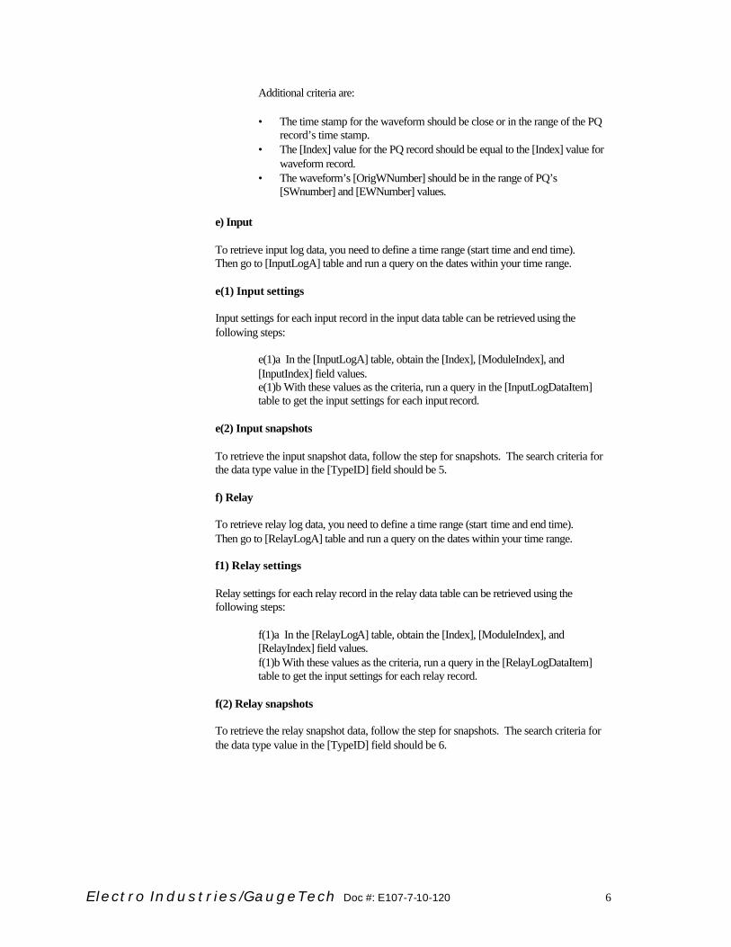
e) Input To retrieve input log data, you need to define a time range (start time and end time). Then go to [InputLogA] table and run a query on the dates within your time range.
e(1) Input settings Input settings for each input record in the input data table can be retrieved using the following steps:
e(1)a In the [InputLogA] table, obtain the [Index], [ModuleIndex], and [InputIndex] field values. e(1)b With these values as the criteria, run a query in the [InputLogDataItem] table to get the input settings for each input record.
e(2) Input snapshots To retrieve the input snapshot data, follow the step for snapshots. The search criteria for the data type value in the [TypeID] field should be 5.
f) Relay To retrieve relay log data, you need to define a time range (start time and end time). Then go to [RelayLogA] table and run a query on the dates within your time range.
f1) Relay settings Relay settings for each relay record in the relay data table can be retrieved using the following steps:
f(1)a In the [RelayLogA] table, obtain the [Index], [ModuleIndex], and [RelayIndex] field values. f(1)b With these values as the criteria, run a query in the [RelayLogDataItem] table to get the input settings for each relay record.
f(2) Relay snapshots To retrieve the relay snapshot data, follow the step for snapshots. The search criteria for the data type value in the [TypeID] field should be 6.

Electro Industries/GaugeTech Doc #: E107-7-10-120 7
6.0 Database definitions
6.1 EIGData.DB
6.1.1 Tables overview Figure_5 shows the tables in the EIGData.DB file, grouped by their function.
6.1.2 Table names Below is the list of all tables in the EIGData.DB file with their table names and descriptions.
Table Name Description * AllEnergyDemandLogs * N/A * AllFlickerLogs * N/A AllHistoricalLogs One record per day for all snapshot log data. AllInputLogs One record per day for all input log data. AllLimitsLogs One record per day for all limit log data. AllLogs One record for every download file been converted. AllPQLogs One record per day for all PQ log data. AllProfiles Device’s profiles at the time of download. AllRelayLogs One record per day for all relay log data. AllWaveformLogs One record per day for all waveform data. DataPoints Available data point Ids stored in all HistLog_xxx sub tables. DeviceInformation Device’s name, address, ID, serial number. * EDLogTmp * N/A * EDTimeIndexTmp * N/A FullScales Device’s full scale values HistLogTimeIndexTmp Template table for snapshot log data. Stores date/time stamps and snapshot type
information. Duplicates for every hour. Duplicated table name is HistLogTimeIndex_yyy_zz, where yyy is the date index from AllHistoricalLogs table and zz is the hour index. Works in pairs with HistLog_yyy_zz table.
HistLogTmp Template table for snapshot log data. Stores primary values and data point IDs. Duplicates for every hour. Duplicated table name is HistLog_yyy_zz, where yyy is the date index from AllHistoricalLogs table and zz is the hour index. Works in pairs with HistLogTime_yyy_zz table.
ID_TABLE This file’s version and description information InputLogA Input log data table. InputLogDataItem Input log settings. LastTimeStamps The last record’s date/time information of each log. Used for partial download in Nexus
Communicator’s download. LimitsLogDataItem Limit log settings LimitsLogTmp Template table for limit log data. Duplicated for each day. Duplicated table name is
LimitsLog_yyy where yyy is the date index from AllLimitsLogs table. PQLogTmp Template table for PQ log data. Duplicated for each day. Duplicated table name is
PQLog_yyy where yyy is the date index from AllPQLogs table. PQWaveLogDataItem PQ/Waveform log settings RelayLogA Relay log data table. RelayLogDataItem Relay log settings. WaveformLogTmp Template table for waveform log data. Duplicated for each day. Duplicated table name is
Waveformlog_yyy where yyy is the date index from AllWaveformLogs table.

Electro Industries/GaugeTech Doc #: E107-7-10-120 8
6.1.3 Remarks
The data file will hold data for one device only. The user should take care of the collection of database files, to make sure the proper file name is assigned and no duplicates exist. To use with Nexus Communicator software, the Nexus device must be assigned and programmed with a unique device name. Then, the software will use that name as the default file name. Almost all data values are in primary form.
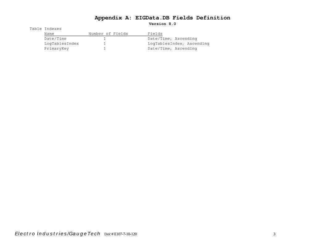
6.1.4 Fields definitions See Appendix A for EIGData.DB file's fields definitions.
6.2 EIGNameList.DB
6.2.1 Tables overview Figure_6 shows the tables in the EIGNameList.DB file, grouped by their function.
6.2.2 Tables Below is the list of all tables in the EIGNameList.DB file with their table names and descriptions.
Table Name Description DataTypes Data type IDs, names, number of bytes, … DeviceProtocol_3_1 Detailed table for EIG Nexus 1250 meter with Modbus RTU protocol.
Contains available data points ID, pointers, indexes, and more data points properties
DeviceProtocolTemplate_3_1 Template data and protocol table for EIG Nexus 1250 meter with Modbus RTU protocol
Devices A list of device IDs and names DevicesAndProtocols Devices and protocol IDs and indexes. ID_Table Information about this file: name, version, … Protocols A list of protocols Type_100 Sub group data for group 100, Device Information. Type_103 Sub group data for group 103, 1 Cycle Type_108 Sub group data for group 108, Max.Thrm.Avg. Type_112 Sub group data for group 112, Energy. Type_113 Sub group data for group 113, Demand. Type_114 Sub group data for group 114, Harm.Mag. Va Type_129 Sub group data for group 129, Phase Angles Type_130 Sub group data for group 130, Fixed Window Avg. Type_131 Sub group data for group 131, Coincident Thrm. Avg. Types Data points group names, IDs, reference table indexes, … TypeTemplate Template table for sub group data points table. Will be created if necessary.
New table name will be Type_xxx where xxx is the data group ID.

Electro Industries/GaugeTech Doc #: E107-7-10-120 9
6.2.3 Remarks
a) All available devices, protocols and data types must be registered to their associated tables.
b) All data IDs are grouped in the Types table. Each group consists of 200 points. The
current starting group ID is 100. The current starting number for data ID is 20000 (200 x 100). Thereafter, every 200 indexes are reserved for any data group.
c) The ReferenceID field in the Types table is for the sub group table’s ID which stores
data point labels of the 200 points within that group (Ex: Type_xxx). A new sub group table must be created if it is necessary. Each sub group table can be referenced to multiple data groups if they use the same labels.
d) DeviceProtocol_y_z is created for one device at one protocol. The template table
DeviceProtocolTemplate_y_z table should be created first. To avoid duplications and indexing conflict, an entry should be made to the DeviceAndProtocols table for every device with one protocol only. These sets of table should be custom designed for the particular device with one protocol. It will serve as the look up table or translate table between the predefined data ID names and the device’s native data name.
6.2.4 How to obtain the data point text label from a data ID
a) Divide the data ID by 200, obtain the integer part only, this is the data group ID. b) Get the modulus of data ID and 200 (divide two numbers and return only the
remainder). This is the sub data ID.
c) Go to Types table. Find the data group ID, text label and its reference ID xxx. d) Go to sub data table Type_xxx, find the sub data ID and its text label.
e) Combine the two text labels, this will be the final text label for the data point.
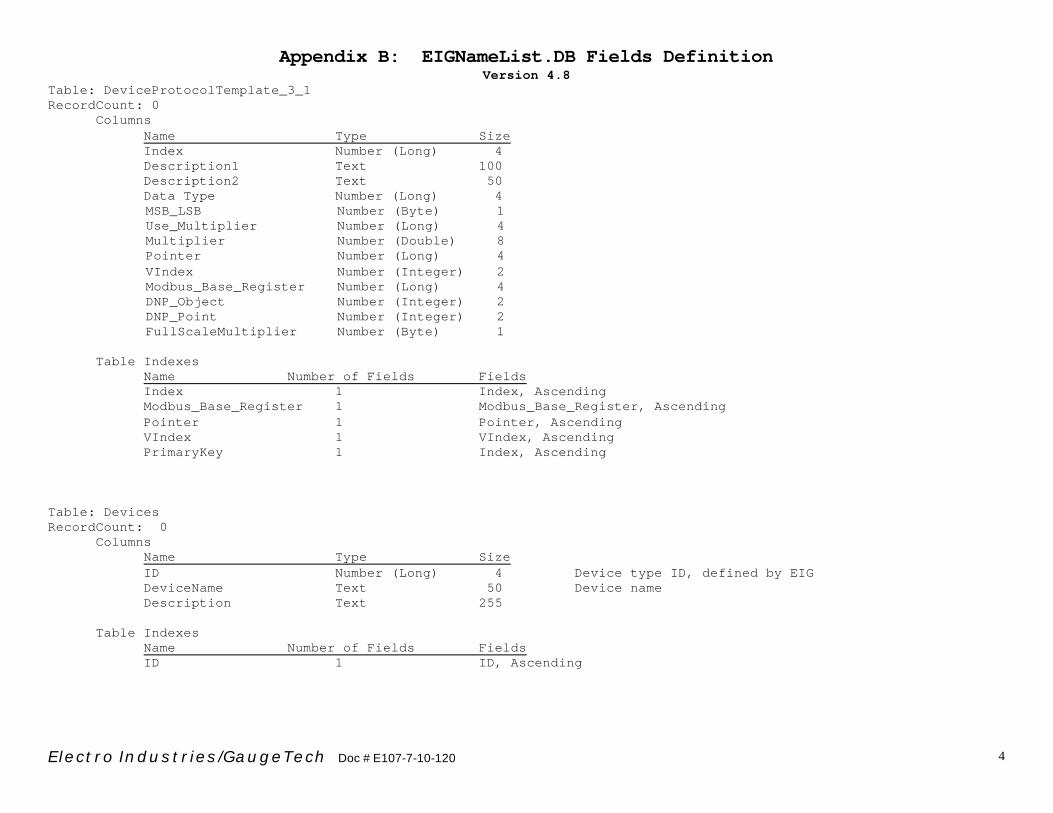
6.2.5 Fields definitions See Appendix B for EIGNameList.DB file’s fields’ definitions.

Electro Industries/GaugeTech Doc #: E107-7-10-120 10
6.3 LogViewTempQuery.DB
6.3.1 Tables overview Figure_7 shows the tables in the LogViewTempQuery.DB file, grouped by function.
6.3.2 Tables Below is a list of all tables in the LogViewTempQuery.DB file with the table names and descriptions.
Table Name Description
AllQueries All query indexes table. Every query must be registered here to obtain a unique query ID.
FullScalesTmp Template table for full scale values. Duplicated for every sub query. Duplicated table name is FullScales_yyy_zz, where yyy is the query index from AllQueries table and zz is the sub query index from HistsubQuery_yy table
HistLogTmp Template table for snapshot log data. Duplicated for every sub query. Duplicated table name is HistLog_yyy_zz where yyy is the query index from AllQueries table and zz is the sub query index from HistSubQuery_yyy table.
HistSubQueryTmp Template table for sub query information of every query. Duplicated for every query. Duplicated table name is HistSubQuery_yyy, where yyy is the query index from AllQueries table. It contains all sub queries indexes for this query.
HlogTimeIndexTmp Template table for snapshot log data. Duplicated for every query. Reusable for its sub queries. It contains sub query’s date/time stamps.
ID_TABLE Information about this database file, version, name, … InputLogATmp Template Table for input log data. InputLogDataItemTmp Template table for input settings. * LimitsLogDataItemTmp * N/A LimitsLogTmp Template table for limit log data. Duplicated for every sub query. Duplicate table
name is LimitsLog_yyy_zz, where yyy is the query index from AllQueries and zz is the sub query index from HistSubQuery_yyy table.
LogDevicesTmp Template table for devices’ information. Duplicated for every query. Duplicated table name is LogDevices_yyy, where yyy is the query index from AllQueries. It contains devices’ name, type, ID, …
* PowerGraphTmp * N/A * PQLogDataItemTmp * N/A PQLogTmp Template table for PQ log data. Duplicated for every sub query.
Duplicated table name is PQLog_yyy_zz, where yyy is query index from AllQueries, and zz is the sub query index from HistSubQuery_yyy table.
PQWaveLogDataItemTmp Template table for PQ and waveform log data. Duplicated for every sub query. Duplicated table name is PQWaveLogDataItem_yyy_zz, where yyy is the query index from AllQueries and zz is the sub query from HistSubQuery_yyy table. It contains the PQ’s and waveform’s settings.
RelayLogATmp Template Table for relay log data. RelayLogADataItemTmp Template Table for relay settings. TagNamesTmp Template table duplicated for every sub query. Duplicated table name is
TagNames_yyy_zz, where yyy is the query index form AllQueries table and zz is the sub query index from HistSubQuery_yyy table. It is mainly used with querying limit log data.
WaveformLogTmp Template table for waveform log data. Duplicated for every sub query. Duplicated table name is Waveformlog_yyy_zz, where yyy is the query index from AllQueries table and zz is the sub query index from HistSubQuery_yyy table.
6.3.3 Fields definitions
See Appendix C for LogViewTempQuery.DB file’s fields definitions.

EIG Nexus Communicator Log Database Files Overview(Data Entry Process)
Nexus CommunicatorSoftware
1) Download log datafrom Nexus device andsave it as binary file(*.NBL).
Nexus Downloaded File(*.NBL)
1) Nexus log file inbinary format.
EIG Log ConverterSoftware
1) Convert Nexusdownloaded file (*NBL)into database file (*DB).2) Delete the sourceNBL file, if conversion issuccessful.
EIG Database File(*.DB)
1) One file per device.
EIGNameList.DB1) Data points look upfile.
EIGData.DB1) Template data file.
Figure_1

EIG Nexus Communicator Log Database Files Overview(Data Display Process)
EIG Database File (*.DB)1) One file per device.
EIG Log Viewer Software
yyyy_mm_dd_hh_nn_ss.TempQuery1) Log Viewer's run time database file.
EIGNameList.DB1) Data points look up file.
LogViewTempQuery.DB1) Log Viewer's templatedatabase file.
Figure_2

Data Process for EIGData.DB
Log converter: convert a binary data file (.nbl) with snapshot,limit, waveform and PQ logs.
AllLogs1) Add one entry for this convert process.2) Obtain unique download index.
AllProfiles1) If it's new profile orprofile changed sincelast update, add newentry.2) Otherwise, do notupdate.
FullScales1) Add new entry forfull scales.
DeviceInformation1) Update device'sinformation.
Start Process Data
AllHistoricalLogs1) Add one entry foreach date.2) Obtain the index (yyy)for each date.3) Update the hour field.If data falls in that hourof that date, obtain thehour index (zz).
AllLimitsLogs1) Add one entry foreach date.2) Obtain the date index(yyy).3) Add entry toLimitsLogDataItem tablewith the download index.
PQWaveLogDataItem1) Add PQ and waveform setup information to thistable with the download index.
AllWaveformLogs1) Add one entry foreach date.2) Obtain the date index(yyy).
AllPQLogs1) Add one entry foreach date.2) Obtain the dateindex (yyy).
HistLog_yyy_zzHistLogTimeIndex_yyy_
zz1) Create these tables, ifthey do not exist. Thesetables are for every hourof every date, if datafalls in that time range.2) Add data.3) UpdateAllHistoricalLogs' totalnumber of records.
LimitsLog_yyy1) Create this table if itdoes not exist.2) Process snapshot logdata, if it exists. (FollowALLHistoricalLogs andHistLog_yyy_zz tablespath).
WaveformLog_yyy1) Create this table, if itdoes not exist.2) Add waveform data.
PQLog_yyy1) Create this tableif it does not exist.2) Add PQ data.
DataPoints1) Obtain the data pointsID from HistLog_yyy_zztable.2) Update this table.
LastTimeStamps1) When each log is finished processing, update this table for log type.
Figure_3

Data Process for LogViewTempQuery.DB(yyyy_mm_dd_hh_nn_ss.TempQuery)
Log Viewer Starts1) Create a new temp query file,yyyy_mm_dd_hh_nn_ss.TempQuery.
AllQueries1) Add entry for every query. Obtain query index - yyy.2) Create data table from template tables based on query type.
Create Supporting Tables1) HistSubQuery_yyy.2) LogDevices_yyy.
Snapshot Group1) Create HistLog_yyy_zz table.2) Create HLogTimeIndex_yyy.3) Update HistSubQuery_yyy and get new sub query index - zz.
Limit Group1) Create LimitsLog_yyy_zz table.2) Update HistSubQuery_yyy and get new sub query index - zz.3) Go to snapshot group to get snapshot records.4) Create TagNames_yyy_zz table.5) Create FullScales_yyy_zz table.
Waveform Group1) Create WaveformLog_yyy_zz.2) Update HistSubQuery_yyy and get new sub query index - zz.3) Create FullScales_yyy_zz table.
PQ Group1) Create PQLog_yyy_zz.2) Update HistSubQuery_yyy and get new sub query index - zz.3) Go to Waveform Group to get waveform records.4) Create FullScales_yyy_zz table.
PQWaveLogDataItem_yyy_zz1) Obtain PQ and Waveform
settings.
Figure_4

EIGData.DB Tables
Template Table Group
1) Snapshot log group: a) HistLogTmp b) HistLogTimeIndexTmp
2) Limit log group: a) LimitsLogTmp
3) Waveform log group: a) WaveformLogTmp
4) PQ log group: a) PQLogTmp
Duplicated Tables
yyy: date indexzz: hour index
1) Snapshot log group:a) HistLog_yyy_zzb) HistLogTimeIndex_yyy_zz
2) Limit log group:a) LimitsLog_yyy
3) Waveform log group:a) WaveformLog_yyy
4) PQ log group:a) PQLog_yyy
Master Table Group
1) AllLogs2) AllProfiles3) DataPoints4) DeviceInformation5) FullScales6) ID_Table7) LastTimeStamps8) InputLogA9) InputLogDataItem10) RelayLogA11)RelayLogDataItem
Index Table Group
1) AllHistoricalLogs2) AllLimitsLogs3) AllWaveformLogs4) AllPQLogs5) AllInputLogs6) AllRelayLogs
Device Setting Table Group
1) LimitsLogDataItem2) PQWaveLogDataItem
Figure_5

EIGNameList.DB
Master Table Group
1) Data Types2) Devices3)DevicesAndProtocols4) ID_Table5) Protocols6) Types
Data Type Table Group
1) Type_1002) Type_1033) Type_1084) Type_1125) Type_1136) Type_1147) Type_1298) Type_1309) Type_131
Template Temple Group
1) Type Template2) DeviceProtocolTemplate_3_1
Detailed Data PointsTable Group
1) DeviceProtocol_3_1
Figure_6

LogViewTempQuery.DB
Master Table Group
1) AllQueries2) ID_Table
Duplicated Table Group
yyy: Query index from AllQuerieszz: Sub Query index fromHistSubQuery_yyy
1) Sub query indexes group: a) HistSubQuery_yyy
2) Device information group: a) LogDevices_yyy
3) Full scales group: a) FullScales_yyy_zz
4) Tag names group: a) TagNames_yyy_zz
5) Snapshot log group: a) HistLog_yyy_zz b) HLogTimeIndex_yyy
6) Limit log group: a) LimitsLog_yyy_zz
7) Waveform log group: a) WaveformLog_yyy_zz
8) PQ log group: a) PQLog_yyy_zz
9) PQ & waveform setting group: a) PQWaveLogDataItem_yyy_zz
10) Input log group: a) InputLogA_yyy_zz b) InputLogDataItem_yyy_zz
11) Relay log group: a) RelayLogA_yyy_zz b) RelayLogDataItem_yyy_zz
Template Table Group
1) Sub Query indexes group: a) HisSubQueryTmp
2) Device Information group: a) LogDevicesTmp
3) Full scales group: a) FullScalesTemp
4) Tag names group: a) TagNamesTmp
5) Snapshot log group: a) HistLogTmp b) HLogTimeIndexTmp
6) Limit log group: a) LimitsLogTmp
7) Waveform log group: a) WaveformLogTmp
8) PQLogTmp: a) PQLogTmp
9) PQ & waveform setting group: a) PQWaveLogDataItemTmp
10) Input log group: a) InputLogATmp b) InputLogDataItemTmp
11) Relay log group: a) RelayLogATmp b) RelayLogDataItemTmp
Figure_7

Appendix A: EIGData.DB Fields Definition Version 8.0
Electro Industries/GaugeTech Doc # E107-7-10-120 1
Table: AllEnergyDemandLogs Table: AllFlickerLogs Table: AllInputLogs Table: AllHistoricalLogs Table: AllLimitsLogs Table: AllLogs Table: AllPQLogs Table: AllProfiles Table: AllRelayLogs Table: AllWaveformLogs Table: DataPoints Table: DeviceInformation Table: EDLogTmp Table: EDTimeIndexTmp Table: FullScales Table: HistLogTimeIndexTmp Table: HistLogTmp Table: ID_TABLE Table: LastTimeStamps Table: LimitsLogDataItem Table: LimitsLogTmp Table: PQLogTmp Table: PQWaveLogDataItem Table: WaveformLogTmp

Appendix A: EIGData.DB Fields Definition Version 8.0
Electro Industries/GaugeTech Doc # E107-7-10-120 2
Table: AllEnergyDemandLogs RecordCount: 0
Columns Name Type Size
LogTablesIndex Number (Long) 4 Sub data table ID Date/Time Date/Time 8
HTable Yes/No 1 Sub data table available status Recs Number (Long) 4 Number of records for that date
Table Indexes Name Number of Fields Fields
Date/Time 1 Date/Time, Ascending LogTablesIndex 1 LogTablesIndex, Ascending
PrimaryKey 1 Date/Time, Ascending Table: AllFlickerLogs RecordCount: 0
Columns Name Type Size LogTablesIndex Number (Long) 4 Sub data table ID Date/Time Date/Time 8
HTable Yes/No 1 Sub data table available status Recs Number (Long) 4 Number of records for that date
Table Indexes Name Number of Fields Fields
Date/Time 1 Date/Time, Ascending LogTablesIndex 1 LogTablesIndex, Ascending
PrimaryKey 1 Date/Time, Ascending Table: AllInputLogs RecordCount: 0
Columns Name Type Size LogTablesIndex Number (Long) 4 Sub data table ID Date/Time Date/Time 8
HTable Yes/No 1 Sub data table available status Recs Number (Long) 4 Number of records for that date
Appendix A: EIGData.DB Fields Definition Version 8.0
Electro Industries/GaugeTech Doc # E107-7-10-120 3
Table Indexes Name Number of Fields Fields
Date/Time 1 Date/Time, Ascending LogTablesIndex 1 LogTablesIndex, Ascending
PrimaryKey 1 Date/Time, Ascending

Appendix A: EIGData.DB Fields Definition Version 8.0
Electro Industries/GaugeTech Doc # E107-7-10-120 4
Table: AllHistoricalLogs RecordCount: 0
Columns Name Type Size
LogTablesIndex Number (Long) 4 Sub data table ID Date/Time Date/Time 8 Hour_0 Yes/No 1 Sub data table available status Hour 0 to 23
Hour_1 Yes/No 1 Hour_2 Yes/No 1
Hour_3 Yes/No 1 Hour_4 Yes/No 1
Hour_5 Yes/No 1 Hour_6 Yes/No 1
Hour_7 Yes/No 1 Hour_8 Yes/No 1
Hour_9 Yes/No 1 Hour_10 Yes/No 1
Hour_11 Yes/No 1 Hour_12 Yes/No 1 Hour_13 Yes/No 1 Hour_14 Yes/No 1
Hour_15 Yes/No 1 Hour_16 Yes/No 1
Hour_17 Yes/No 1 Hour_18 Yes/No 1
Hour_19 Yes/No 1 Hour_20 Yes/No 1
Hour_21 Yes/No 1 Hour_22 Yes/No 1
Hour_23 Yes/No 1 Recs_0 Number (Long) 4 Number of records for the hour Hour 0 to 23
Recs_1 Number (Long) 4 Recs_2 Number (Long) 4
Recs_3 Number (Long) 4 Recs_4 Number (Long) 4 Recs_5 Number (Long) 4 Recs_6 Number (Long) 4
Recs_7 Number (Long) 4

Appendix A: EIGData.DB Fields Definition Version 8.0
Electro Industries/GaugeTech Doc # E107-7-10-120 5
Recs_8 Number (Long) 4 Recs_9 Number (Long) 4
Recs_10 Number (Long) 4 Recs_11 Number (Long) 4
Recs_12 Number (Long) 4 Recs_13 Number (Long) 4
Recs_14 Number (Long) 4 Recs_15 Number (Long) 4
Recs_16 Number (Long) 4 Recs_17 Number (Long) 4
Recs_18 Number (Long) 4 Recs_19 Number (Long) 4
Recs_20 Number (Long) 4 Recs_21 Number (Long) 4
Recs_22 Number (Long) 4 Recs_23 Number (Long) 4
Table Indexes
Name Number of Fields Fields Date/Time 1 Date/Time, Ascending
LogTablesIndex 1 LogTablesIndex, Ascending PrimaryKey 1 Date/Time, Ascending
Table: AllLimitsLogs RecordCount: 0
Columns Name Type Size LogTablesIndex Number (Long) 4 Sub data table ID Date/Time Date/Time 8
HTable Yes/No 1 Sub data table available status Recs Number (Long) 4 Number of records for that date
Table Indexes Name Number of Fields Fields
Date/Time 1 Date/Time, Ascending LogTablesIndex 1 LogTablesIndex, Ascending
PrimaryKey 1 Date/Time, Ascending Table: AllLogs

Appendix A: EIGData.DB Fields Definition Version 8.0
Electro Industries/GaugeTech Doc # E107-7-10-120 6
RecordCount: 0 Columns
Name Type Size Index Number (Long) 4 Download index
EntryDate/Time Date/Time 8 LogOptionID1 Number (Long) 4 Value is the sum of these values:
a1) No data available = 0 a2) Programming File = 1 a3) Historical Log Profile = 2 a4) Event Log Profile = 4 a5) Waveform Log Profile = 8 a6) Programming Block = 16 a7) Historical Log = 32 a8) Log 1 = 64 a9) Log 2 = 128 a10) Energy/Demand Log = 256 a11) Limit Log = 512 a12) Input Log = 1024 a13) Relay Log = 2048 a14) Flicker Log = 4096 a15) Waveform Log = 8192 a16) Power Quality Log = 16384
LogOptionID2 Number (Long) 4 Reserved LogOptionName Memo - Log option text names
ProFileIndex Number (Long) 4 ProFileIndex in the AllProfiles table LogConverterVersion Text 255 Log Converter version number, format: v#.#.# where # is the numerical value. LogConverterInfo Text 255 Log converter description. DownloadSoftwareInfo Text 255
FirmwareInfo1 Text 255 FirmwareInfo2 Text 255 FirmwareInfo3 Text 255 FirmwareInfo4 Text 255 FirmwareInfo5 Text 255
Table Indexes
Name Number of Fields Fields Table Indexes EntryDate/Time 1 EntryDate/Time, Ascending
Index 1 Index, Ascending PrimaryKey 1 Index, Ascending

Appendix A: EIGData.DB Fields Definition Version 8.0
Electro Industries/GaugeTech Doc # E107-7-10-120 7
Table: AllPQLogs RecordCount: 0
Columns Name Type Size LogTablesIndex Number (Long) 4 Sub data table ID Date/Time Date/Time 8
HTable Yes/No 1 Sub data table available status Recs Number (Long) 4 Number of records for that date
Table Indexes Name Number of Fields Fields
Date/Time 1 Date/Time, Ascending LogTablesIndex 1 LogTablesIndex, Ascending
PrimaryKey 1 Date/Time, Ascending Table: AllProfiles RecordCount: 0 Columns
Name Type Size ProfileIndex Number (Long) 4 Profile entry index Date/Time Date/Time 8 Profile modification date/time
ms Number (Integer) 2 Millisecond DTmode Number (Integer) 2 Date/time mode, reserved
Profile Memo - Binary value of device’s programming setup information.
Table Indexes Name Number of Fields Fields Date/Time 1 Date/Time, Ascending
PrimaryKey 1 ProfileIndex, Ascending ProfileIndex 1 ProfileIndex, Ascending Table: AllRelayLogs RecordCount: 0
Columns Name Type Size LogTablesIndex Number (Long) 4 Sub data table ID Date/Time Date/Time 8
HTable Yes/No 1 Sub data table available status

Appendix A: EIGData.DB Fields Definition Version 8.0
Electro Industries/GaugeTech Doc # E107-7-10-120 8
Recs Number (Long) 4 Number of records for that date
Table Indexes Name Number of Fields Fields Index 1 LogTablesIndex, Ascending
PrimaryKey 1 Date/Time, Ascending Table: AllWaveformLogs RecordCount: 0
Columns Name Type Size LogTablesIndex Number (Long) 4 Sub data table ID Date/Time Date/Time 8
HTable Yes/No 1 Sub data table available status Recs Number (Long) 4 Number of records for that date
Table Indexes Name Number of Fields Fields
Date/Time 1 Date/Time, Ascending LogTablesIndex 1 LogTablesIndex, Ascending
PrimaryKey 1 Date/Time, Ascending Table: DataPoints RecordCount: 0
Columns Name Type Size
DataID Number (Long) 4 Data points ID, defined in EIGNameList.DB
Table Indexes Name Number of Fields Fields DataID 1 DataID, Ascending
PrimaryKey 1 DataID, Ascending Table: DeviceInformation RecordCount: 0
Columns

Appendix A: EIGData.DB Fields Definition Version 8.0
Electro Industries/GaugeTech Doc # E107-7-10-120 9
Name Type Size DeviceTypeID Number (Long) 4 Device ID, defined in EIGNameList.DB DeviceType Text 50 Device name in text Address Number (Long) 4 HardwareID Text 255 For Nexus, it is factory pre assigned ID HardwareName Text 255 For Nexus, it is user assigned name TimeZone Text 10 HardwareTypeName Text 255 Device’s native hardware name, such as
“0107 Nexus 1250” Table: EDLogTmp Table is reserved RecordCount: 0
Columns Name Type Size
Date/TimeIndex Number (Long) 4 DataID Number (Long) 4 Value Text 30
Table Indexes Name Number of Fields Fields DataID 1 DataID, Ascending Date/TimeIndex 1 Date/TimeIndex, Ascending Table: EDTimeIndexTmp Table is reserved RecordCount: 0
Columns Name Type Size Date/TimeIndex Number (Long) 4
Date/Time Date/Time 8 ms Number (Integer) 2 DTmode Number (Integer) 2

Appendix A: EIGData.DB Fields Definition Version 8.0
Electro Industries/GaugeTech Doc # E107-7-10-120 10
Table Indexes
Name Number of Fields Fields Date/TimeIndex 1 Date/TimeIndex, Ascending Table: FullScales RecordCount: 0
Columns Name Type Size Index Number (Long) 4 Download index PTCT_Ratio1 Text 255 CT ratio PTCT_Ratio2 Text 255 CT aux ratio
PTCT_Ratio3 Text 255 PT ratio PTCT_Ratio4 Text 255 PT aux ratio FullScale1 Text 50 I a,b,c FullScale2 Text 50 I n FullScale3 Text 50 V an, bn, cn FullScale4 Text 50 V aux FullScale5 Text 50 V ab, bc, ca FullScale6 Text 50 Power-phase FullScale7 Text 50 Power-total FullScale8 Text 50 Frequency
Table Indexes Name Number of Fields Fields Index 1 Index, Ascending
PrimaryKey 1 Index, Ascending Table: HistLogTimeIndexTmp RecordCount: 0
Columns Name Type Size Date/TimeIndex Number (Long) 4 Timestamp index
Date/Time Date/Time 8 ms Number (Integer) 2 Milliseconds DTmode Number (Integer) 2 Date/Time mode
TypeID Number (Integer) 2 a1) Log 1 snapshots = 2 a2) Log 2 snapshots = 3 a3) Limit snapshots = 4

Appendix A: EIGData.DB Fields Definition Version 8.0
Electro Industries/GaugeTech Doc # E107-7-10-120 11
a4) Waveform snapshots = 8
Table Indexes Name Number of Fields Fields
Date/TimeIndex 1 Date/TimeIndex, Ascending Date/TimeIndex 1 Date/TimeIndex, Ascending PrimaryKey 1 Date/TimeIndex, Ascending Table: HistLogTmp RecordCount: 0
Columns Name Type Size
Date/TimeIndex Number (Long) 4 Timestamp index in the HistLogTimeIndexTmp table DataID Number (Long) 4 Data point ID Value Number (Double) 8 Data value in primary format
Table Indexes Name Number of Fields Fields DataID 1 DataID, Ascending Date/TimeIndex 1 Date/TimeIndex, Ascending Table: ID_TABLE RecordCount: 1
Columns Name Type Size
Name Text 50 Reserved Version Number (Double) 8 Database version KeyName Text 50 Reserved Note Text 255 Table: LastTimeStamps RecordCount: 0
Columns Name Type Size
LogID Number (Long) 4 a1) Profile = 0 a2) Log 1 = 1

Appendix A: EIGData.DB Fields Definition Version 8.0
Electro Industries/GaugeTech Doc # E107-7-10-120 12
a3) Log 2 = 2 a4) Limits = 3 a5) Limit snapshots = 4 a6) Waveform trigger = 10 a7) Waveform sample = 12 a8) PQ = 13
LogName Text 10 LastDateTime Date/Time 8 Last record date/Time. For profile, it is last modified date/time. Lastms Number (Integer) 2 Last record millisecond time LastDTmode Number (Integer) 2 Last record date/time mode
LastRecNum Number (Long) 4 Last Record number. For profile, it is the check sum Value.
LastRecOffSet Number (Long) 4 Reserved
Table Indexes Name Number of Fields Fields
PrimaryKey 1 LogID, Ascending Table: LimitsLogDataItem RecordCount: 0
Columns Name Type Size
LinkIndex Number (Long) 4 Refrence number Index Number (Long) 4 Download index DataID Number (Long) 4 Data point ID DataIndex Number (Integer) 2 Data point position number, reserved LimitID Number (Long) 4 1=Above, 2=Below LSet Number (Double) 8 Limit set value LSAB Text 255 Above or Below LSet% Number (Double) 8 Limit set % of full scale
Table Indexes Name Number of Fields Fields
DataID 1 DataID, Ascending DataIndex 1 DataIndex, Ascending Index 1 Index, Ascending
LimitID 1 LimitID, Ascending LinkIndex 1 LinkIndex, Ascending

Appendix A: EIGData.DB Fields Definition Version 8.0
Electro Industries/GaugeTech Doc # E107-7-10-120 13
Table: LimitsLogTmp RecordCount: 0
Columns Name Type Size
LinkIndex Number (Long) 4 LinkIndex in table LimitsLogDataItem StartDate/Time Date/Time 8 Startms Number (Integer) 2 Start millisecond SDTMode Number (Integer) 2 Start date/time mode EndDate/Time Date/Time 8 Endms Number (Integer) 2 End millisecond EDTMode Number (Integer) 2 End date/time mode LState Text 8 Limit conditions: Above or Below Duration Number (Double) 8 Duration is in seconds LValue Number (Double) 8 Snapshot value
DescriptionCode Number (Integer) 2 a1) Above = 1 a2) Below = 2 a3) Normal = 0 a4) Start Point = -1 a5) End Point = -2
Index Number (Long) 4 Download index DataID Number (Long) 4
Table Indexes Name Number of Fields Fields
DataID 1 DataID, Ascending EndDate/Time 1 EndDate/Time, Ascending LinkIndex 1 LinkIndex, Ascending StartDate/Time 1 StartDate/Time, Ascending Table: PQLogTmp RecordCount: 0
Columns Name Type Size
StartDate/Time Date/Time 8 PQ’s start date/time Startms Number (Integer) 2 Start millisecond SDTMode Number (Integer) 2 Start date/time mode
SWNumber Number (Integer) 2 unadjusted waveform number which the start PQ point is in that waveform
Ssample Number (Integer) 2 unadjusted waveform sample point, which is the start PQ point

Appendix A: EIGData.DB Fields Definition Version 8.0
Electro Industries/GaugeTech Doc # E107-7-10-120 14
EndDate/Time Date/Time 8 PQ’s end date/time Endms Number (Integer) 2 End millisecond EDTMode Number (Integer) 2 End date/time mode
EWNumber Number (Integer) 2 unadjusted waveform number which the end PQ point is in that waveform
ESample Number (Integer) 2 unadjusted waveform sample point, which is theend PQ point
Index Number (Long) 4 download index Duration Number (Double) 8 calculated duration in milliseconds
ChannelID Number (Integer) 2 Van = 0 Vbn = 1 Vcn = 2 Vaux = 3 Ia = 4 Ib = 5 Ic = 6 Iaux = 7 In = 8 Vab = 9 Vbc = 10 Vca = 11 Input 1 = 12 Input 2 = 13 Input 3 = 14 Input 4 = 15 Input 5 = 16 Input 6 = 17 Input 7 = 18 Input 8 = 19
PQValue Number (Double) 8 the peak RMS value during the PQ event PQ% Number (Double) 8 PQvalue in percent of full-scale value ChannelName Text 16
ConditionCode Number (Integer) 2 Normal = 0 Surge = 1 Sag = 2 Start point = -1 End point = -2
ConditionName Text 16 WaveformLink Yes/No 1
Table Indexes

Appendix A: EIGData.DB Fields Definition Version 8.0
Electro Industries/GaugeTech Doc # E107-7-10-120 15
Name Number of Fields Fields Date/Time 1 StartDate/Time, Ascending
EndDate/Time 1 EndDate/Time, Ascending Index 1 Index, Ascending

Appendix A: EIGData.DB Fields Definition Version 8.0
Electro Industries/GaugeTech Doc # E107-7-10-120 16
Table: PQWaveLogDataItem RecordCount: 0
Columns Name Type Size
Index Number (Long) 4 Download index SampleRate Number (Integer) 2 CaptureNum Number (Integer) 2 Number of captures Mode Number (Integer) 2 Capture mode HSI Number (Integer) 2 HIS setting value C0_L1 Number (Double) 8 Limit 1 set values
Van = 0 Vbn = 1 Vcn = 2 Vaux = 3 Ia = 4 Ib = 5 Ic = 6 Iaux = 7 In = 8 Vab = 9 Vbc = 10 Vca = 11
C1_L1 Number (Double) 8 C2_L1 Number (Double) 8 C3_L1 Number (Double) 8 C4_L1 Number (Double) 8 C5_L1 Number (Double) 8 C6_L1 Number (Double) 8 C7_L1 Number (Double) 8 C8_L1 Number (Double) 8 C9_L1 Number (Double) 8 C10_L1 Number (Double) 8 C11_L1 Number (Double) 8 C0_L2 Number (Double) 8 Limit 2 set values C1_L2 Number (Double) 8 C2_L2 Number (Double) 8 C3_L2 Number (Double) 8 C4_L2 Number (Double) 8 C5_L2 Number (Double) 8 C6_L2 Number (Double) 8 C7 L2 Number (Double) 8

Appendix A: EIGData.DB Fields Definition Version 8.0
Electro Industries/GaugeTech Doc # E107-7-10-120 17
C8_L2 Number (Double) 8 C9_L2 Number (Double) 8 C10_L2 Number (Double) 8 C11_L2 Number (Double) 8 C0_L1SAB Text 8 Limit 1 set states: Above or Below C1_L1SAB Text 8 C2_L1SAB Text 8 C3_L1SAB Text 8 C4_L1SAB Text 8 C5_L1SAB Text 8 C6_L1SAB Text 8 C7_L1SAB Text 8 C8_L1SAB Text 8 C9_L1SAB Text 8 C10_L1SAB Text 8 C11_L1SAB Text 8 C0_L2SAB Text 8 Limit 2 set states: Above or Below C1_L2SAB Text 8 C2_L2SAB Text 8 C3_L2SAB Text 8 C4_L2SAB Text 8 C5_L2SAB Text 8 C6_L2SAB Text 8 C7_L2SAB Text 8 C8_L2SAB Text 8 C9_L2SAB Text 8 C10_L2SAB Text 8 C11_L2SAB Text 8
WaveEnables Number (Long) 4 Channel enables for waveform capture. Bit 0 is LSB. Values are:
Van, L1 = Bit 0 Van, L2 = Bit 1 Vbn, L1 = Bit 2 Vbn, L2 = Bit 3 Vcn, L1 = Bit 4 Vcn, L2 = Bit 5 Vaux, L1 = Bit 6 Vaux, L2 = Bit 7 Ia, L1 = Bit 8 Ia, L2 = Bit 9 Ib, L1 = Bit 10

Appendix A: EIGData.DB Fields Definition Version 8.0
Electro Industries/GaugeTech Doc # E107-7-10-120 18
Ib, L2 = Bit 11 Ic, L1 = Bit 12 Ic, L2 = Bit 13 Iaux, L1 = Bit 14 Iaux, L2 = Bit 15 In, L1 = Bit 16 In, L2 = Bit 17 Vab, L1 = Bit 18 Vab, L2 = Bit 19 Vbc, L1 = Bit 20 Vbc, L2 = Bit 21 Vca, L1 = Bit 22 Vca, L2 = Bit 23
WaveEnables_Input Number (Byte) 1 Input channels enables for waveform capture. Input 1 is bit 0, LSB, input 8 is bit 7, MSB.
PQEnables Number (Long) 4 Channel enables for PQ capture. Bit 0 is LSB. Values are the same as WaveEnables.
PQEnables_Input Number (Byte) 1 Input channels enables for PQ capture. Input 1 is bit 0, LSB, input 8 is bit 7, MSB.
HookUp Number (Long) 4 a1) Wye = 0 a2) Delta = 1 a3) 2 CTs = 2 a4) 2.5 elements = 3 a5) Grounded Delta= 4
RecordFormat Number (Long) 4 256 Sampling Rate: Volts = 0, current = 1 512 Sampling Rate: Volts a,b,c = 0-2 Current a,b,c,Iaux = 4-7 None = 3
RecordFormat is used for waveforms with 256 and 512 sampling rates. For 256 Sampling Rate: Volts = 0, the waveform will contain all 3 voltages and all 8 inputs data. Current = 1, the waveform will contain all 3 currents and data from all 8 inputs. For 512 Sampling Rate:

Appendix A: EIGData.DB Fields Definition Version 8.0
Electro Industries/GaugeTech Doc # E107-7-10-120 19
Volts a,b,c = 0,1,2 Current a,b,b,Iaux = 4,5,6,7 None = 3 The waveform will contain any single analog channel and data from all 8 inputs.
Table Indexes Name Number of Fields Fields
Index 1 Index, Ascending PrimaryKey 1 Index, Ascending

Appendix A: EIGData.DB Fields Definition Version 8.0
Electro Industries/GaugeTech Doc # E107-7-10-120 20
Table: WaveformLogTmp RecordCount: 0
Columns Name Type Size
Date/Time Date/Time 8 Date/time at the end of the triggering cycle ms Number (Integer) 2 Millisecond at the end of the triggering cycle DTMode Number (Integer) 2 Date/time mode at the end of the triggering cycle WaveformNumber Number (Integer) 2 Adjusted waveform number, starting at 1. TriggeredBy1 Text 255 Trigger description TriggeredBy2 Text 255 Trigger description
TriggerCode Number (Long) 4 What channel caused this waveform capture. Usually is the channel whose state was changed. Van, L1 = Bit 0 Van, L2 = Bit 1 Vbn, L1 = Bit 2 Vbn, L2 = Bit 3 Vcn, L1 = Bit 4 Vcn, L2 = Bit 5 Vaux, L1 = Bit 6 Vaux, L2 = Bit 7 Ia, L1 = Bit 8 Ia, L2 = Bit 9 Ib, L1 = Bit 10 Ib, L2 = Bit 11 Ic, L1 = Bit 12 Ic, L2 = Bit 13 Iaux, L1 = Bit 14 Iaux, L2 = Bit 15 In, L1 = Bit 16 In, L2 = Bit 17 Vab, L1 = Bit 18 Vab, L2 = Bit 19 Vbc, L1 = Bit 20 Vbc, L2 = Bit 21 Vca, L1 = Bit 22 Vca, L2 = Bit 23 Input 1 = Bit 24 Input 2 = Bit 25 Input 3 = Bit 26 Input 4 = Bit 27 Input 5 = Bit 28

Appendix A: EIGData.DB Fields Definition Version 8.0
Electro Industries/GaugeTech Doc # E107-7-10-120 21
Input 6 = Bit 29 Input 7 = Bit 30 Input 8 = Bit 31 * Bit value 1 = triggered. Bit value 0 = not triggered.
ConditionCode Number (Long) 4 conditions for all channels. Van, L1 = Bit 0 Van, L2 = Bit 1 Vbn, L1 = Bit 2 Vbn, L2 = Bit 3 Vcn, L1 = Bit 4 Vcn, L2 = Bit 5 Vaux, L1 = Bit 6 Vaux, L2 = Bit 7 Ia, L1 = Bit 8 Ia, L2 = Bit 9 Ib, L1 = Bit 10 Ib, L2 = Bit 11 Ic, L1 = Bit 12 Ic, L2 = Bit 13 Iaux, L1 = Bit 14 Iaux, L2 = Bit 15 In, L1 = Bit 16 In, L2 = Bit 17 Vab, L1 = Bit 18 Vab, L2 = Bit 19 Vbc, L1 = Bit 20 Vbc, L2 = Bit 21 Vca, L1 = Bit 22 Vca, L2 = Bit 23 * Bit value 1 = condition exceeded. Bit value 0 = condition not exceeded.
ConditionCode_Input Number (Integer) 2 Inputs conditions. Input 1 is bit 0 (LSB) and input 8 is bit 7 (MSB). State 1= 1 and state 0 = 0.
Index Number (Long) 4 Download index V0 Number (Double) 8 Van RMS V1 Number (Double) 8 Vbn RMS V2 Number (Double) 8 Vcn RMS V3 Number (Double) 8 Vaux RMS

Appendix A: EIGData.DB Fields Definition Version 8.0
Electro Industries/GaugeTech Doc # E107-7-10-120 22
V4 Number (Double) 8 Ia RMS V5 Number (Double) 8 Ib RMS V6 Number (Double) 8 Ic RMS V7 Number (Double) 8 Iaux RMS V8 Number (Double) 8 In RMS V9 Number (Double) 8 Vab RMS V10 Number (Double) 8 Vbc RMS V11 Number (Double) 8 Vca RMS WaveformTriggerNumber Number (Integer) 2 Triggered by a waveform with the same value in fields
WaveformNumber Contiguous Yes/No 1 CaptureSequence Number (Integer) 2 0=first,1 or more=additional to the first SampleInTriggerCyc Number (Integer) 2 Number of samples in the triggering cycle EndTriggerCycPT Number (Integer) 2 End point for the triggering cycle TimingPT Number (Integer) 2 Sample point with a timestampe value in Date/Time
field Sample0 Memo - SampleX: Holds the tab-delimited string of waveform
samples value, where X is: Van/ab = 0
Vbn/bc = 1 Vcn/ca = 2 Ia = 3 Ib = 4 Ic = 5 Iaux = 6 Input 1 to 8 = 7 to 14 • Special cases for delta mode and 2.5 elements mode:
Delta, 3CT: a) Recalculate Vab, bc, ca values.
Delta, 2CT: a) Recalculate Vab, bc, ca values. b) Ib should be re-calculated from Ib= -Ia-Ib.
2.5 element: a) Vb should be re-calculated from Vb= -Va-Vc
For waveform with 256 sampling rate, fields Sample0 and Sample1 hold the data for Channel 1, fields Sample2 and Sample3 for Channel 2, fields Sample4 and Sample5 for Channel 3. They can be either volts or current. Each field has 1024 samples. There is a total of 2048 samples per channel in a capture.

Appendix A: EIGData.DB Fields Definition Version 8.0
Electro Industries/GaugeTech Doc # E107-7-10-120 23
For waveform with 512 sampling rate, fields Sample0, Sample1, Sample2 and Sample3 hold the data for a single analog channel. Each field has 1024 samples. There is a total of 4096 samples per single channel in a capture. For waveform with 256 and 512 sampling rates, the user must reconstruct the data for a channel by concatenating the data in multiple fields. Data from Waveform Inputs for Input 1 to Input 8 are always in fields Sample7 to Sample14.
Sample1 Memo - Sample2 Memo - Sample3 Memo - Sample4 Memo - Sample5 Memo - Sample6 Memo - Sample7 Memo - Sample8 Memo - Sample9 Memo - Sample10 Memo - Sample11 Memo -
Sample12 Memo - Sample13 Memo - Sample14 Memo - WTDate/Time Date/Time 8 WTms Number (Integer) 2 WTDTmode Number (Integer) 2 OrigFirstSample Number (Long) 4 unadjusted first sample index with in the waveform
capture OrigFirstWave Number (Long) 4 unadjusted first waveform number OrigWNumber Number (Integer) 2 unadjusted waveform number WSDT Date/Time 8 calculated waveform start date/time WSms Number (Integer) 2 calculated waveform start millisecond WSDTmode Number (Long) 4 calculated waveform start date/time mode WEDT Date/Time 8 calculated waveform end date/Time WEms Number (Integer) 2 calculated waveform end millisecond WEDTmode Number (Integer) 2 calculated waveform end date/time mode WDuration Number (Double) 8 calculated waveform duration in milliseconds

Appendix A: EIGData.DB Fields Definition Version 8.0
Electro Industries/GaugeTech Doc # E107-7-10-120 24
Table Indexes
Name Number of Fields Fields Date/Time 1 Date/Time, Ascending ms 1 ms, Ascending Table: InputLogA Columns
Name Type Size
Index Number (Long) 4 Download index
DT1 Date/Time 8 Start date/time ms1 Number (Integer) 2 Start ms DT1mode Number (Integer) 2 Start date/time mode DT2 Date/Time 8 End date/time ms2 Number (Integer) 2 End ms DT2mode Number (Integer) 2 End date/time mode
ModuleIndex Number (Integer) 2 Input module index, 0 for internal input,
>0 for external intput modules InputIndex Number (Integer) 2 Input channel index, normaly is 1 to 8. Status Number (Byte) 1 Input status, 0 or 1. DescriptionCode Number (Integer) 2 0 for normal record, -1 for start point, -2 for end point. Duration Number (Double) 8 Input change duration in milliseconds. Table: InputLogDataItem Columns
Name Type Size
Index Number (Long) 4 Download index ModuleIndex Number (Integer) 2 Input module index, 0 for internal input, >0 for external input modules ModulePort Number (Byte) 1 External input module connected to Nexus’ port. ModuleAddress Number (Long) 4 Input module address. InputIndex Number (Integer) 2 Input channel index, normally is 1 to 8. ModuleLabel Text 20 Module label. InputLabel Text 20 Input channel label

Appendix A: EIGData.DB Fields Definition Version 8.0
Electro Industries/GaugeTech Doc # E107-7-10-120 25
TextLabel_0 Text 20 Description for state 0. TextLabel_1 Text 20 Description for state 1. NormalState Number (Integer) 2 Normal state, 0 or 1. InputFlip Number (Long) 4 0 = No Flip, 1 = Flipped. Table: RelayLogA Columns
Name Type Size Index Number (Long) 4 Download index ModuleIndex Number (Integer) 2 Module index RelayIndex Number (Integer) 2 Relay channel index DT1 Date/Time 8 Stage 1 (trigger) date/time ms1 Number (Integer) 2 Stage 1 (trigger) ms DT1mode Number (Integer) 2 Stage 1 (trigger) date/time mode DT2 Date/Time 8 Stage 2 (command) date/time ms2 Number (Integer) 2 Stage 2 (command) ms DT2mode Number (Integer) 2 Stage 2 (command) date/time mode DT3 Date/Time 8 Stage 3 (acknowledge) date/time ms3 Number (Integer) 2 Stage 3 (acknowledge) ms DT3mode Number (Integer) 2 Stage 3 (acknowledge) date/time DT1CK Number (Integer) 2 Stage 1 date/time status, -1=OK, 0=invalid. If value is 0, then Condition0, Condition1,
condition0Text, Condition1Text, InputInfo1x, InputStatus, and GateStatus will be invalid.
DT2CK Number (Integer) 2 Stage 2 date/time status DT3CK Number (Integer) 2 Stage 3 date/time status Duration12 Number (Double) 8 Duration between stage 1 and 2 in ms Duration23 Number (Double) 8 Duration between stage 2 and 3 in ms Duration13 Number (Double) 8 Duration between stage 1 and 3 in ms Condition0 Number (Integer) 2 Relay condition before stage 1 0 = De-energized 1 = Energized 2 = Locked, De-energized 3 = Locked, Energized Condition1 Number (Integer) 2 Relay condition at stage 1 Condition2 Number (Integer) 2 Relay condition at stage 2 Condition3 Number (Integer) 2 Relay condition at stage 3 Condition0Text Text 255 Relay condition description before stage 1 Condition1Text Text 255 Relay condition description at stage 1 Condition2Text Text 255 Relay condition description at stage 2

Appendix A: EIGData.DB Fields Definition Version 8.0
Electro Industries/GaugeTech Doc # E107-7-10-120 26
Condition3Text Text 255 Relay condition description at stage 3 InputInfo11 Text 25 Input value 1 for ElectroLogic at stage 1 InputInfo12 Text 25 Input value 2 for ElectroLogic at stage 1 InputInfo13 Text 25 Input value 3 for ElectroLogic at stage 1 InputInfo14 Text 25 Input value 4 for ElectroLogic at stage 1 InputInfo15 Text 25 Input value 5 for ElectroLogic at stage 1 InputInfo16 Text 25 Input value 6 for ElectroLogic at stage 1 InputInfo17 Text 25 Input value 7 for ElectroLogic at stage 1 InputInfo18 Text 25 Input value 8 for ElectroLogic at stage 1 InputStatus Number (Long) 4 Input status for ElectroLogic at stage 1, each bit indicates state 0 or 1 for each input. Bit 0 = input 1 Bit 1 = input 2 . . Bit 20= input 21 For Futura, Bit 21 = Phase Imb. Bit 22 = Phase Reversal GateStatus Number (Long) 4 Gate status for ElectroLogic at stage 1, each bit indicates state 0 or 1 for each gate. Bit 0 = gate A Bit 1 = gate B Bit 2 = gate C Bit 3 = gate D Bit 4 = gate E Bit 5 = gate F Bit 6 = gate G InputStatusB Number (Long) 4 Additional Input Status for Futura Bit 0 = Input 22 Bit 1 = Input 23 InputInfo19 Text 25 . InputInfo54 Text 25 For Futura, offset index by 10. (Inputs 19 through 54) See Logicstrxx in Table: RelayLogDataItem.

Appendix A: EIGData.DB Fields Definition Version 8.0
Electro Industries/GaugeTech Doc # E107-7-10-120 27
Table: RelayLogDataItem Columns
Name Type Size Index Number (Long) 4 Download index ModuleIndex Number (Integer) 2 Relay module index ModuleAddress Number (Long) 4 Relay module address ModuleLabel Text 20 Module label
ModulePort Number (Byte) 1 External relay module connected to Nexus’ port. ModuleSlot Number (Byte) 1 Module slot number.
RelayIndex Number (Integer) 2 Relay index. RelayLabel Text 20 Relay label SetDelay Number (Byte) 1 Set delay time in sec. ResetDelay Number (Byte) 1 Reset delay time in sec. LogicStr1 Text 255 ElectroLogic input 1 setting LogicStr2 Text 255 ElectroLogic input 2 setting LogicStr3 Text 255 ElectroLogic input 3 setting LogicStr4 Text 255 ElectroLogic input 4 setting LogicStr5 Text 255 ElectroLogic input 5 setting LogicStr6 Text 255 ElectroLogic input 6 setting LogicStr7 Text 255 ElectroLogic input 7 setting LogicStr8 Text 255 ElectroLogic input 8 setting LogicComb1 Number (Byte) 1 ElectroLogic gate A type Bit 4: negate combination (AND -> NAND) Bit 3-2: 00 = AND 01 = OR 10 = XOR 11 = Hysteresis Bit 1: 1 = invert gate input 2 Bit 0: 1 = invert gate input 1 LogicComb2 Number (Byte) 1 ElectroLogic gate B type LogicComb3 Number (Byte) 1 ElectroLogic gate C type LogicComb4 Number (Byte) 1 ElectroLogic gate D type LogicComb5 Number (Byte) 1 ElectroLogic gate E type LogicComb6 Number (Byte) 1 ElectroLogic gate F type LogicComb7 Number (Byte) 1 ElectroLogic gate G type LogicComb8 Number (Byte) 1 ElectroLogic gate H type TextLabel_0 Text 20 Relay state 0 description TextLabel_1 Text 20 Relay state 1 description

Appendix A: EIGData.DB Fields Definition Version 8.0
Electro Industries/GaugeTech Doc # E107-7-10-120 28
NormalState Number (Byte) 1 Relay normal state: 0 or 1 Logic1Type Number (Integer) 2 ElectroLogic input 1 Type 1 = Limit logic 2 = Inputs Logic2Type Number (Integer) 2 ElectroLogic input 2 Type Logic3Type Number (Integer) 2 ElectroLogic input 3 Type Logic4Type Number (Integer) 2 ElectroLogic input 4 Type Logic5Type Number (Integer) 2 ElectroLogic input 5 Type Logic6Type Number (Integer) 2 ElectroLogic input 6 Type Logic7Type Number (Integer) 2 ElectroLogic input 7 Type Logic8Type Number (Integer) 2 ElectroLogic input 8 Type Logic1ID Number (Long) 4 ElectroLogic input 1 data ID For Limit type: Global data ID # For Input type: Input channel # Logic2ID Number (Long) 4 ElectroLogic input 2 data ID Logic3ID Number (Long) 4 ElectroLogic input 3 data ID Logic4ID Number (Long) 4 ElectroLogic input 4 data ID Logic5ID Number (Long) 4 ElectroLogic input 5 data ID Logic6ID Number (Long) 4 ElectroLogic input 6 data ID Logic7ID Number (Long) 4 ElectroLogic input 7 data ID Logic8ID Number (Long) 4 ElectroLogic input 8 data ID LogicStr10 Text 255 For Futura, the order is: . Van, Vbn, Vcn, Vab, Vbc, Vca, Ia, Ib, Ic, In . W, VAR, VA, PF, Freq, THD-Va, THD-Vb, THD-Vc LogicStr44 Text 255 THD-Ia, THD-Ib, THD-Ic, 1-21 for Limit1
22-42 for Limit2 43 = Phase Imb. 44 = Phase Imb. Hysteresis Number (Long) 4 0 = Disabled, 1 = Enabled LogicControl Number (Long) 4 1 = Positive, -1 = Negative

Appendix B: EIGNameList.DB Fields Definition Version 4.8
Electro Industries/GaugeTech Doc # E107-7-10-120 1
Table: DataTypes Table: DeviceProtocol_3_1 Table: DeviceProtocolTemplate_3_1 Table: Devices Table: DevicesAndProtocols Table: Type_100 Table: Type_103 Table: Type_108 Table: Type_112 Table: Type_113 Table: Type_114 Table: Type_129 Table: Type_130 Table: Type_131 Table: Types Table: TypeTemplate

Appendix B: EIGNameList.DB Fields Definition Version 4.8
Electro Industries/GaugeTech Doc # E107-7-10-120 2
Table: DataTypes RecordCount: 23
Columns Name Type Size ID Number (Long) 4 Data type ID Bytes Number (Long) 4 Number of bytes UseFullScale Number (Long) 4 Use value in the next field: 0=No, 1=Yes DefaultFullScale Number (Double) 8 Unit Number (Double) 8 Additional multiplying factor Name Text 50 Description Text 255
Table Indexes Name Number of Fields Fields ID 1 ID, Ascending
Table: DeviceProtocol_3_1 For Nexus with Modbus protocol RecordCount: 2040 Columns Name Type Size
Index Number (Long) 4 Data ID number Description1 Text 100 Description2 Text 50 Data Type Number (Long) 4 Data type ID MSB_LSB Number (Byte) 1 0=N/A, 1=MSB, 2=LSB
Use_Multiplier Number (Long) 4 0=None, 1=CT Ratio, 2=CT Ratio AUX, 3=PT Ratio, 4=PT Ratio AUX, 5=PT and CT Ratio, 6=use value in next field, [Multiplier], reserved value from 10-49 for Analog Inputs in groups of 1x, 2x, 3x, 4x. Ex. 25 is for Module 2, Channel 6 (0 based).
Multiplier Number (Double) 8 Pointer Number (Long) 4 Nexus data pointer number VIndex Number (Integer) 2 Nexus data index number Modbus_Base_Register Number (Long) 4 Reserved DNP_Object Number (Integer) 2 Reserved DNP_Point Number (Integer) 2 Reserved
FullScaleMultiplier Number (Byte) 1 0=None, 1-I, 2-In, 3=Vp_n, 4=Vp_p, 5=Vaux, 6=Power_p, 7=Power_T, 8=Frequency

Appendix B: EIGNameList.DB Fields Definition Version 4.8
Electro Industries/GaugeTech Doc # E107-7-10-120 3
Table Indexes Name Number of Fields Fields Index 1 Index, Ascending
Modbus_Base_Register 1 Modbus_Base_Register, Ascending Pointer 1 Pointer, Ascending VIndex 1 VIndex, Ascending
Appendix B: EIGNameList.DB Fields Definition Version 4.8
Electro Industries/GaugeTech Doc # E107-7-10-120 4
Table: DeviceProtocolTemplate_3_1 RecordCount: 0
Columns Name Type Size
Index Number (Long) 4 Description1 Text 100 Description2 Text 50 Data Type Number (Long) 4
MSB_LSB Number (Byte) 1 Use_Multiplier Number (Long) 4 Multiplier Number (Double) 8 Pointer Number (Long) 4 VIndex Number (Integer) 2 Modbus_Base_Register Number (Long) 4 DNP_Object Number (Integer) 2 DNP_Point Number (Integer) 2 FullScaleMultiplier Number (Byte) 1
Table Indexes
Name Number of Fields Fields Index 1 Index, Ascending
Modbus_Base_Register 1 Modbus_Base_Register, Ascending Pointer 1 Pointer, Ascending VIndex 1 VIndex, Ascending
PrimaryKey 1 Index, Ascending Table: Devices RecordCount: 0 Columns Name Type Size
ID Number (Long) 4 Device type ID, defined by EIG DeviceName Text 50 Device name
Description Text 255
Table Indexes Name Number of Fields Fields ID 1 ID, Ascending

Appendix B: EIGNameList.DB Fields Definition Version 4.8
Electro Industries/GaugeTech Doc # E107-7-10-120 5
Table: DevicesAndProtocols RecordCount: 1 Columns Name Type Size
Index Number (Long) 4 Record entry number DevID Number (Long) 4 Device ID in table Devices, field ID ProtocolID Number (Long) 4 Protocol ID in table Protocols, field ID Description Text 255
Table Indexes Name Number of Fields Fields DevID 1 DevID, Ascending
Index 1 Index, Ascending ProtocolID 1 ProtocolID, Ascending
Table: ID_Table RecordCount: 1 Columns Name Type Size
Version Number (Double) 8 Database version number Date/Time Created Date/Time 8 Name Text 255 Description Text 255 Last Moification Date/Time By User Date/Time 8 Table: Protocols RecordCount: 0 Columns Name Type Size
ID Number (Long) 4 Protocol ID, defined by EIG Name Text 50 Protocol name Description Text 255
Table Indexes
Name Number of Fields Fields ID 1 ID, Ascending

Appendix B: EIGNameList.DB Fields Definition Version 4.8
Electro Industries/GaugeTech Doc # E107-7-10-120 6
Table: Type_100 RecordCount: 17 Columns Name Type Size
ID Number (Long) 4 Sub group data ID Name Text 50
Description Text 255
Table Indexes Name Number of Fields Fields ID 1 ID, Ascending
Table: Type_103 RecordCount: 38 Columns Name Type Size
ID Number (Long) 4 Sub group data ID Name Text 50 Description Text 255
Table Indexes Name Number of Fields Fields ID 1 ID, Ascending
Table: Type_108 RecordCount: 62 Columns Name Type Size
ID Number (Long) 4 Sub group data ID Name Text 50 Description Text 255 Table Indexes
Name Number of Fields Fields ID 1 ID, Ascending

Appendix B: EIGNameList.DB Fields Definition Version 4.8
Electro Industries/GaugeTech Doc # E107-7-10-120 7
Table: Type_112 RecordCount: 28 Columns Name Type Size
ID Number (Long) 4 Sub group data ID Name Text 50 Description Text 255
Table Indexes
Name Number of Fields Fields ID 1 ID, Ascending
Table: Type_113 RecordCount: 7 Columns Name Type Size
ID Number (Long) 4 Sub group data ID Name Text 50 Description Text 255
Table Indexes Name Number of Fields Fields ID 1 ID, Ascending
Table: Type_114 RecordCount: 129 Columns Name Type Size
ID Number (Long) 4 Sub group data ID Name Text 50 Description Text 255 Table Indexes
Name Number of Fields Fields ID 1 ID, Ascending

Appendix B: EIGNameList.DB Fields Definition Version 4.8
Electro Industries/GaugeTech Doc # E107-7-10-120 8
Table: Type_129 RecordCount: 12 Columns Name Type Size
ID Number (Long) 4 Sub group data ID Name Text 50 Description Text 255
Table Indexes
Name Number of Fields Fields ID 1 ID, Ascending
Table: Type_130 RecordCount: 33 Columns Name Type Size
ID Number (Long) 4 Sub group data ID Name Text 50
Description Text 255
Table Indexes Name Number of Fields Fields ID 1 ID, Ascending
Table: Type_131 RecordCount: 5 Columns Name Type Size
ID Number (Long) 4 Sub group data ID Name Text 50 Description Text 255
Table Indexes Name Number of Fields Fields ID 1 ID, Ascending

Appendix B: EIGNameList.DB Fields Definition Version 4.8
Electro Industries/GaugeTech Doc # E107-7-10-120 9
Table: Types RecordCount: 33
Columns Name Type Size
ID Number (Long) 4 Data group ID ReferenceID Number (Long) 4 Data group refrence ID Name Text 50 Data group name Description Text 255
BaseNumber Number (Long) 4 Reserved
Table Indexes Name Number of Fields Fields ID 1 ID, Ascending
ReferenceID 1 ReferenceID, Ascending
Table: TypeTemplate RecordCount: 1 Columns Name Type Size
ID Number (Long) 4 Sub group data ID Name Text 50 Description Text 255 Table Indexes
Name Number of Fields Fields ID 1 ID, Ascending

Appendix C: LogViewTempQuery.DB Fields Definition Version 8.0
Electro Industries/GaugeTech Doc # E107-7-10-120 1
Table: AllQueries Table: FullScalesTmp Table: HistLogTmp Table: HistSubQueryTmp Table: HLogTimeIndexTmp Table: ID_TABLE Table: LimitsLogDataItemTmp Table: LimitsLogTmp Table: LogDevicesTmp Table: PowerGraphTmp Table: PQLogDataItemTmp Table: PQLogTmp Table: PQWaveLogDataItemTmp Table: TagNamesTmp Table: WaveformLogTmp

Appendix C: LogViewTempQuery.DB Fields Definition Version 8.0
Electro Industries/GaugeTech Doc # E107-7-10-120 2
Table: AllQueries RecordCount: 0 Columns Name Type Size
QueryIndex Number (Long) 4 User query entry ID StartDate/Time Date/Time 8 Query start time EndDate/Time Date/Time 8 Query end time
QueryType Number (Long) 4 Reserved
Table Indexes Name Number of Fields Fields Index 1 QueryIndex, Ascending
PrimaryKey 1 QueryIndex, Ascending
Table: FullScalesTmp RecordCount: 0 Columns Name Type Size
Index Number (Long) 4 Device’s download index PTCT_Ratio1 Text 255 Same as in Appendix A PTCT_Ratio2 Text 255 PTCT_Ratio3 Text 255 PTCT_Ratio4 Text 255 FullScale1 Text 50 FullScale2 Text 50 FullScale3 Text 50 FullScale4 Text 50 FullScale5 Text 50 FullScale6 Text 50 FullScale7 Text 50 FullScale8 Text 50 DeviceIndex Number (Long) 4 DeviceIndex in LogDevicesTmp table

Appendix C: LogViewTempQuery.DB Fields Definition Version 8.0
Electro Industries/GaugeTech Doc # E107-7-10-120 3
Table: HistLogTmp RecordCount: 0
Columns Name Type Size
DeviceIndex Number (Long) 4 Query device index Date/Time Date/Time 8 ms Number (Integer) 2 Millisecond DTMode Number (Integer) 2 Date/time mode TypeID Number (Integer) 2 Snapshot ID DataID Number (Long) 4 Data point ID Value Number (Double) 8
Table Indexes Name Number of Fields Fields DataID 1 DataID, Ascending
Date/Time 1 Date/Time, Ascending DeviceIndex 1 DeviceIndex, Ascending
DTMode 1 DTMode, Ascending ms 1 ms, Ascending TypeID 1 TypeID, Ascending Table: HistSubQueryTmp RecordCount: 0
Columns Name Type Size
SubQIndex Number (Long) 4 Sub query index SDate/Time Date/Time 8 Sub query start date/time EDate/Time Date/Time 8 Sub query end date/time
Table Indexes Name Number of Fields Fields
PrimaryKey 1 SubQIndex, Ascending

Appendix C: LogViewTempQuery.DB Fields Definition Version 8.0
Electro Industries/GaugeTech Doc # E107-7-10-120 4
Table: HLogTimeIndexTmp RecordCount: 0
Columns Name Type Size
Date/TimeIndex Number (Long) 4 Timestampe index Date/Time Date/Time 8 ms Number (Integer) 2 Millisecond DTMode Number (Integer) 2 Date/time mode TypeID Number (Integer) 2 Snapshot type ID
Table Indexes Name Number of Fields Fields
Date/Time 1 Date/Time, Ascending Date/TimeIndex 1 Date/TimeIndex, Ascending Table: ID_TABLE RecordCount: 1
Columns Name Type Size
Name Text 50 Reserved Version Number (Double) 8 Database version KeyName Text 50 Reserved Note Text 255 Reserved

Appendix C: LogViewTempQuery.DB Fields Definition Version 8.0
Electro Industries/GaugeTech Doc # E107-7-10-120 5
Table: LimitsLogDataItemTmp RecordCount: 0
Columns Name Type Size
Index Number (Long) 4 Download index DataID Number (Long) 4 Data point ID DataIndex Number (Integer) 2 Data point position index LSet Number (Double) 8 Same as in Appendix A LSAB Text 8 LSet% Number (Double) 8 LimitID Number (Long) 4 DeviceIndex Number (Long) 4 Query device index
Table Indexes Name Number of Fields Fields DataID 1 DataID, Ascending
DataIndex 1 DataIndex, Ascending Index 1 Index, Ascending LimitID 1 LimitID, Ascending

Appendix C: LogViewTempQuery.DB Fields Definition Version 8.0
Electro Industries/GaugeTech Doc # E107-7-10-120 6
Table: LimitsLogTmp RecordCount: 0
Columns Name Type Size
DeviceIndex Number (Long) 4 Query device index StartDate/Time Date/Time 8 Same as in Appendix A Startms Number (Integer) 2 SDTMode Number (Integer) 2 EndDate/Time Date/Time 8
Endms Number (Integer) 2 EDTMode Number (Integer) 2 DataID Number (Long) 4 LState Text 255 LimitID Number (Long) 4 Duration Number (Double) 8 LValue Number (Double) 8 DescriptionCode Number (Integer) 2 LSet Number (Double) 8
LSAB Text 255 LSet% Number (Double) 8
Table Indexes Name Number of Fields Fields DataID 1 DataID, Ascending
EndDate/Time 1 EndDate/Time, Ascending LimitID 1 LimitID, Ascending StartDate/Time 1 StartDate/Time, Ascending

Appendix C: LogViewTempQuery.DB Fields Definition Version 8.0
Electro Industries/GaugeTech Doc # E107-7-10-120 7
Table: LogDevicesTmp RecordCount: 0
Columns Name Type Size
DeviceIndex Number (Long) 4 Query device index DeviceTypeID Number (Long) 4 Device type ID in EIGNamelist.DB DBPath Text 255 Device’s DB file path HardwareName Text 255 Device’s user assigned text name TimeZone Text 10 HardwareTypeName Text 255 Device’s native hardware name such as “0107 Nexus 1250”
Table Indexes Name Number of Fields Fields DeviceIndex 1 DeviceIndex, Ascending
Table: PowerGraphTmp RecordCount: 0
Columns Name Type Size
PGraphIndex Number (Long) 4 QueryDT Date/Time 8

Appendix C: LogViewTempQuery.DB Fields Definition Version 8.0
Electro Industries/GaugeTech Doc # E107-7-10-120 8
Table: PQLogDataItemTmp RecordCount: 0
Columns Name Type Size
Index Number (Long) 4 Device’s download index C0_L1 Number (Double) 8 Same as in Appendix A C1_L1 Number (Double) 8 C2_L1 Number (Double) 8 C3_L1 Number (Double) 8 C4_L1 Number (Double) 8 C5_L1 Number (Double) 8 C6_L1 Number (Double) 8 C7_L1 Number (Double) 8 C8_L1 Number (Double) 8 C9_L1 Number (Double) 8 C10_L1 Number (Double) 8 C11_L1 Number (Double) 8 C0_L2 Number (Double) 8 C1_L2 Number (Double) 8 C2_L2 Number (Double) 8 C3_L2 Number (Double) 8 C4_L2 Number (Double) 8 C5_L2 Number (Double) 8 C6_L2 Number (Double) 8 C7_L2 Number (Double) 8 C8_L2 Number (Double) 8 C9_L2 Number (Double) 8 C10_L2 Number (Double) 8 C11_L2 Number (Double) 8 C0_L1SAB Text 8 C1_L1SAB Text 8 C2_L1SAB Text 8 C3_L1SAB Text 8 C4_L1SAB Text 8 C5_L1SAB Text 8 C6_L1SAB Text 8 C7_L1SAB Text 8 C8_L1SAB Text 8 C9_L1SAB Text 8 C10_L1SAB Text 8 C11_L1SAB Text 8 C0_L2SAB Text 8 C1_L2SAB Text 8

Appendix C: LogViewTempQuery.DB Fields Definition Version 8.0
Electro Industries/GaugeTech Doc # E107-7-10-120 9
C2_L2SAB Text 8 C3_L2SAB Text 8
C4_L2SAB Text 8 C5_L2SAB Text 8 C6_L2SAB Text 8 C7_L2SAB Text 8 C8_L2SAB Text 8 C9_L2SAB Text 8 C10_L2SAB Text 8 C11_L2SAB Text 8 DeviceIndex Number (Long) 4 Query device index
Table Indexes Name Number of Fields Fields Index 1 Index, Ascending

Appendix C: LogViewTempQuery.DB Fields Definition Version 8.0
Electro Industries/GaugeTech Doc # E107-7-10-120 10
Table: PQLogTmp RecordCount: 0
Columns Name Type Size
DeviceIndex Number (Long) 4 Query device index StartDate/Time Date/Time 8 Same as in Appendix A Startms Number (Integer) 2 SDTMode Number (Integer) 2 SWNumber Number (Integer) 2 SSample Number (Integer) 2 EndDate/Time Date/Time 8 Endms Number (Integer) 2 EDTMode Number (Integer) 2 EWNumber Number (Integer) 2 ESample Number (Integer) 2 Index Number (Long) 4 Duration Number (Double) 8 ChannelID Number (Integer) 2 PQValue Number (Double) 8 PQ% Number (Double) 8 ChannelName Text 16 ConditionCode Number (Integer) 2 ConditionName Text 16 WaveformLink Yes/No 1 RecCounter Number (Long) 4 Reserved, Log Viewer run time counter
Table Indexes Name Number of Fields Fields Date/Time 1 StartDate/Time, Ascending
ms 1 Startms, Ascending PQsIndex 1 RecCounter, Ascending

Appendix C: LogViewTempQuery.DB Fields Definition Version 8.0
Electro Industries/GaugeTech Doc # E107-7-10-120 11
Table: PQWaveLogDataItemTmp RecordCount: 0
Columns Name Type Size
DeviceIndex Number (Long) 4 Query device index Index Number (Long) 4 Device’s download index SampleRate Number (Integer) 2 Same as in Appendix A CaptureNum Number (Integer) 2 Mode Number (Integer) 2 HSI Number (Integer) 2 C0_L1 Number (Double) 8 C1_L1 Number (Double) 8 C2_L1 Number (Double) 8 C3_L1 Number (Double) 8 C4_L1 Number (Double) 8 C5_L1 Number (Double) 8 C6_L1 Number (Double) 8 C7_L1 Number (Double) 8 C8_L1 Number (Double) 8 C9_L1 Number (Double) 8 C10_L1 Number (Double) 8 C11_L1 Number (Double) 8 C0_L2 Number (Double) 8 C1_L2 Number (Double) 8 C2_L2 Number (Double) 8 C3_L2 Number (Double) 8 C4_L2 Number (Double) 8 C5_L2 Number (Double) 8 C6_L2 Number (Double) 8 C7_L2 Number (Double) 8 C8_L2 Number (Double) 8 C9_L2 Number (Double) 8 C10_L2 Number (Double) 8 C11_L2 Number (Double) 8 C0_L1SAB Text 8 C1_L1SAB Text 8 C2_L1SAB Text 8 C3_L1SAB Text 8 C4_L1SAB Text 8 C5_L1SAB Text 8 C6_L1SAB Text 8 C7_L1SAB Text 8 C8_L1SAB Text 8

Appendix C: LogViewTempQuery.DB Fields Definition Version 8.0
Electro Industries/GaugeTech Doc # E107-7-10-120 12
C9_L1SAB Text 8 C10_L1SAB Text 8
C11_L1SAB Text 8 C0_L2SAB Text 8 C1_L2SAB Text 8 C2_L2SAB Text 8 C3_L2SAB Text 8 C4_L2SAB Text 8 C5_L2SAB Text 8 C6_L2SAB Text 8 C7_L2SAB Text 8 C8_L2SAB Text 8 C9_L2SAB Text 8 C10_L2SAB Text 8 C11_L2SAB Text 8 WaveEnables Number (Long) 4 WaveEnables_Input Number (Byte) 1 PQEnables Number (Long) 4 PQEnables_Input Number (Byte) 1 HookUp Number (Long) 4 RecordFormat Number (Long) 4 256 Sampling Rate: volts=0, current=1 512 Sampling Rate: volts a,b,c=0-2 current a,b,c=4-7
Table Indexes None=3 Name Number of Fields Fields Index 1 Index, Ascending
Table: TagNamesTmp RecordCount: 0
Columns Name Type Size
LogSource Number (Long) 4 Reserved DataID Number (Long) 4 Data point ID TextName Text 255 Dta point text name GridColIndex Number (Long) 4 Reserved PGColIndex Number (Long) 4 Reserved
Table Indexes Name Number of Fields Fields GDataID 1 DataID, Ascending

Appendix C: LogViewTempQuery.DB Fields Definition Version 8.0
Electro Industries/GaugeTech Doc # E107-7-10-120 13
Table: WaveformLogTmp RecordCount: 0
Columns Name Type Size
DeviceIndex Number (Long) 4 Query device index Index Number (Long) 4 Device’s download index Date/Time Date/Time 8 Same as in Appendix A ms Number (Integer) 2 DTMode Number (Integer) 2 WaveformNumber Number (Integer) 2 TriggeredBy1 Text 255 TriggeredBy2 Text 255 TriggerCode Number (Long) 4 ConditionCode Number (Long) 4 ConditionCode_Input Number (Integer) 2 V0 Number (Double) 8 V1 Number (Double) 8 V2 Number (Double) 8 V3 Number (Double) 8 V4 Number (Double) 8 V5 Number (Double) 8 V6 Number (Double) 8 V7 Number (Double) 8 V8 Number (Double) 8 V9 Number (Double) 8 V10 Number (Double) 8 V11 Number (Double) 8 WaveformTriggerNumber Number (Integer) 2 Contiguous Yes/No 1 CaptureSequence Number (Integer) 2 SampleInTriggerCyc Number (Integer) 2 EndTriggerCycPT Number (Integer) 2 TimingPT Number (Integer) 2 Sample0 Memo - Sample1 Memo - Sample2 Memo - Sample3 Memo - Sample4 Memo - Sample5 Memo - Sample6 Memo - Sample7 Memo - Sample8 Memo - Sample9 Memo -

Appendix C: LogViewTempQuery.DB Fields Definition Version 8.0
Electro Industries/GaugeTech Doc # E107-7-10-120 14
Sample10 Memo - Sample11 Memo -
Sample12 Memo - Sample13 Memo - Sample14 Memo - WTDate/Time Date/Time 8 WTms Number (Integer) 2 WTDTmode Number (Integer) 2 OrigFirstSample Number (Long) 4 OrigFirstWave Number (Long) 4 OrigWNumber Number (Integer) 2 WSDT Date/Time 8 WSms Number (Integer) 2 WSDTmode Number (Long) 4 WEDT Date/Time 8 WEms Number (Integer) 2 WEDTmode Number (Integer) 2 WDuration Number (Double) 8 RecCounter Number (Long) 4 Reserved, Log Viewer run time counter
Table Indexes Name Number of Fields Fields Date/Time 1 Date/Time, Ascending
ms 1 ms, Ascending OrigWNum 1 OrigWNumber, Ascending RecCounter 1 RecCounter, Ascending Table: InputLogATmp Columns
Name Type Size DeviceIndex Number (Long) 4 Index Number (Long) 4 DT1 Date/Time 8 ms1 Number (Integer) 2 DT1mode Number (Integer) 2 DT2 Date/Time 8 ms2 Number (Integer) 2 DT2mode Number (Integer) 2 ModuleIndex Number (Integer) 2 InputIndex Number (Integer) 2 Status Number (Byte) 1

Appendix C: LogViewTempQuery.DB Fields Definition Version 8.0
Electro Industries/GaugeTech Doc # E107-7-10-120 15
DescriptionCode Number (Integer) 2 Duration Number (Double) 8 GIndex Number (Long) 4 Table: InputLogDataItemTmp Columns
Name Type Size DeviceIndex Number (Long) 4 Index Number (Long) 4 ModuleIndex Number (Integer) 2 ModulePort Number (Byte) 1 ModuleAddress Number (Long) 4 InputIndex Number (Integer) 2 ModuleLabel Text 20 InputLabel Text 20 TextLabel_0 Text 20 TextLabel_1 Text 20 NormalState Number (Integer) 2 InputFlip Number (Long) 4 0 = No Flip, 1 = Flipped
Table: RelayLogATmp
Columns
Name Type Size DeviceIndex Number (Long) 4 Index Number (Long) 4 ModuleIndex Number (Integer) 2 RelayIndex Number (Integer) 2 DT1 Date/Time 8 ms1 Number (Integer) 2 DT1mode Number (Integer) 2 DT2 Date/Time 8 ms2 Number (Integer) 2 DT2mode Number (Integer) 2 DT3 Date/Time 8 ms3 Number (Integer) 2 DT3mode Number (Integer) 2 DT1CK Number (Integer) 2 DT2CK Number (Integer) 2 DT3CK Number (Integer) 2 Duration12 Number (Double) 8 Duration23 Number (Double) 8
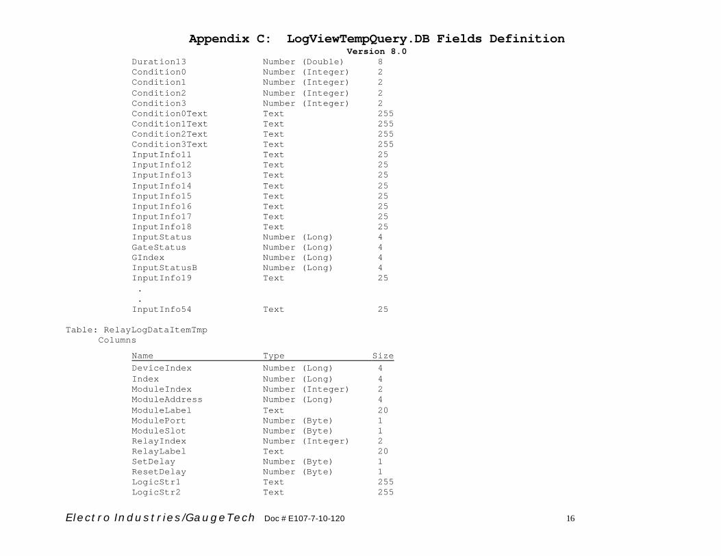
Appendix C: LogViewTempQuery.DB Fields Definition Version 8.0
Electro Industries/GaugeTech Doc # E107-7-10-120 16
Duration13 Number (Double) 8 Condition0 Number (Integer) 2 Condition1 Number (Integer) 2 Condition2 Number (Integer) 2 Condition3 Number (Integer) 2 Condition0Text Text 255 Condition1Text Text 255 Condition2Text Text 255 Condition3Text Text 255 InputInfo11 Text 25 InputInfo12 Text 25 InputInfo13 Text 25 InputInfo14 Text 25 InputInfo15 Text 25 InputInfo16 Text 25 InputInfo17 Text 25 InputInfo18 Text 25 InputStatus Number (Long) 4 GateStatus Number (Long) 4 GIndex Number (Long) 4 InputStatusB Number (Long) 4 InputInfo19 Text 25 . . InputInfo54 Text 25 Table: RelayLogDataItemTmp Columns
Name Type Size DeviceIndex Number (Long) 4 Index Number (Long) 4 ModuleIndex Number (Integer) 2 ModuleAddress Number (Long) 4 ModuleLabel Text 20 ModulePort Number (Byte) 1 ModuleSlot Number (Byte) 1 RelayIndex Number (Integer) 2 RelayLabel Text 20 SetDelay Number (Byte) 1 ResetDelay Number (Byte) 1 LogicStr1 Text 255 LogicStr2 Text 255
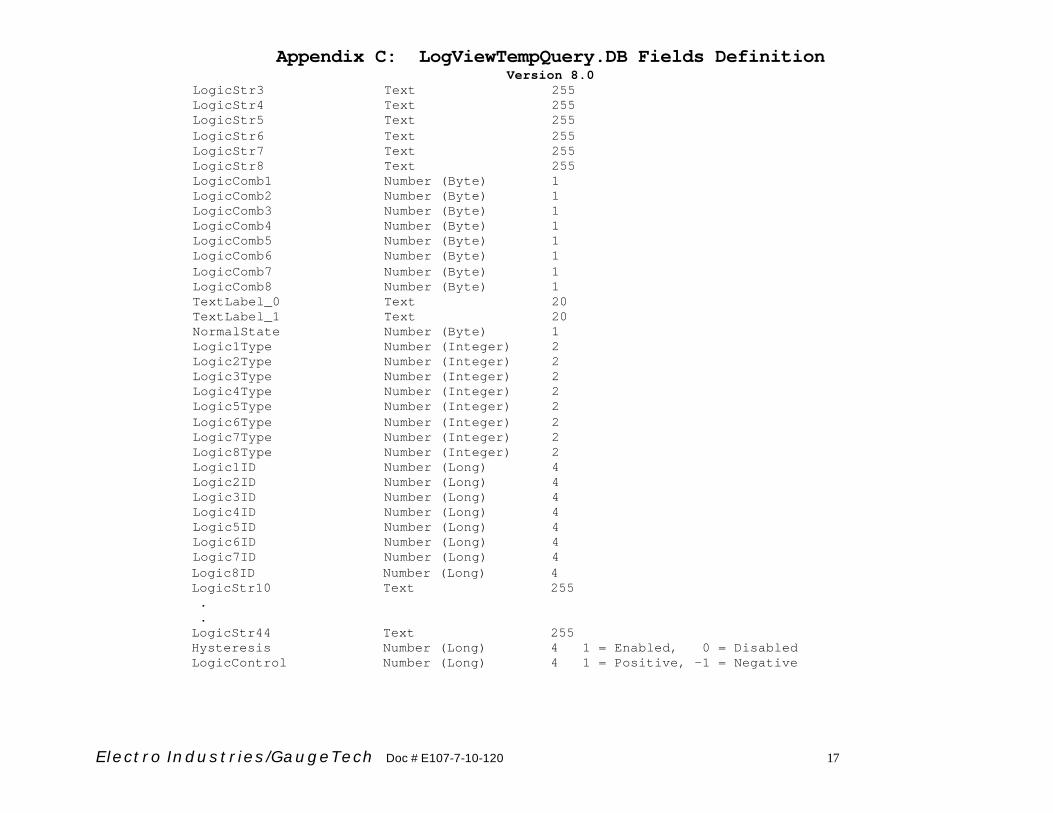
Appendix C: LogViewTempQuery.DB Fields Definition Version 8.0
Electro Industries/GaugeTech Doc # E107-7-10-120 17
LogicStr3 Text 255 LogicStr4 Text 255 LogicStr5 Text 255 LogicStr6 Text 255 LogicStr7 Text 255 LogicStr8 Text 255 LogicComb1 Number (Byte) 1 LogicComb2 Number (Byte) 1 LogicComb3 Number (Byte) 1 LogicComb4 Number (Byte) 1 LogicComb5 Number (Byte) 1 LogicComb6 Number (Byte) 1 LogicComb7 Number (Byte) 1 LogicComb8 Number (Byte) 1 TextLabel_0 Text 20 TextLabel_1 Text 20 NormalState Number (Byte) 1 Logic1Type Number (Integer) 2 Logic2Type Number (Integer) 2 Logic3Type Number (Integer) 2 Logic4Type Number (Integer) 2 Logic5Type Number (Integer) 2 Logic6Type Number (Integer) 2 Logic7Type Number (Integer) 2 Logic8Type Number (Integer) 2 Logic1ID Number (Long) 4 Logic2ID Number (Long) 4 Logic3ID Number (Long) 4 Logic4ID Number (Long) 4 Logic5ID Number (Long) 4 Logic6ID Number (Long) 4 Logic7ID Number (Long) 4 Logic8ID Number (Long) 4 LogicStr10 Text 255 . . LogicStr44 Text 255 Hysteresis Number (Long) 4 1 = Enabled, 0 = Disabled LogicControl Number (Long) 4 1 = Positive, -1 = Negative

Electro Industries/GaugeTech Doc # E107-7-10-120
Appendix D: EIGData.DB Fields Relationships Format: [Table Name]|(Field name) 1) General
a) Master download index: [AllLogs]|(Index), used by many other sub tables. [LimitsLogDataItem]|(Index) [PQWaveLogDataItem]|(Index) [FullScales]|(Index) [LimitsLog_y]|(Index) [PQLog_y]|(Index) [WaveformLog_y]|(Index)
b) Device profile index: [AllLogs]|(ProFileIndex) = [AllProfiles]|(ProFileIndex)
c) Available data points IDs for this device file: [DataPoints]|(DataID). Its corresponding text name can be obtained from EIGNamelist.DB file. Values are collected from all [HistLog_y_z] table’s (DataID) field.
2) Snapshots
a) Date Index (y): [AllHistoricalLogs]|(LogTablesIndex) b) Hour Index (z, 0 to 23): status field (Hour_x) in [AllHistoricalLogs]
table. If (Hour_x) is true, then the hour index (z) is set to that hour.
c) Sub data tables set: [HistLogTimeIndex_y_z] and [HistLog_y_z] d) [HistLogTimeIndex_y_z]|(Date/TimeIndex) =
[HistLog_y_z]|(Date/TimeIndex)
3) Limits a) Date Index (y): [AllLimitsLogs]|(LogTablesIndex) b) Sub data table: [LimitsLog_y] c) Limit settings: [LimitsLog_y]|(Index) = [LimitsLogDataItem]|(Index),
[LimitsLog_y]|(LinkIndex) =LimitsLogDataItem]|(LinkIndex),
[LimitsLog_y]|(DataID) = [LimitsLogDataItem]|(DataID).
4) PQs a) Date index (y): [AllPQLogs]|(LogTablesIndex) b) Sub data table: [PQLog_y] c) PQ setting: [PQLog_y]|(Index) = [PQWaveLogDataItem]|(Index)
Linked waveforms: If there are waveform records associated with a PQ record, the value for [WaveformLink] field in the [Pqlog_y] table should be True. To obtain the waveform data, follow the steps for retrieving waveform data. But some additional criteria should be used. C1) Find the waveform data using the retrieve waveform data steps. Additional criteria are: • [WaveformLog_y]|(Date/Time) should be in the range of
[PQLog_y]|(StartDate/Time) and [PQLog_y]|(EndDate/Time). • The [PQLog_y]|(Index) = [WaveformLog_y]|(Index). • [WaveformLog_y]|(OrigWNumber) should be in the range of
[PQLog_y]|(SWnumber) and [PQLog_y]|(EWnumber).
5) Waveforms: a) Date index (y): [AllWaveformLogs]|(LogTablesIndex) b) Sub date table: [WaveformLog_y] d) Waveform setting: [WaveformLog_y]|(Index) = [PQWaveLogDataItem]|(Index)