new instrumentation for pharmaceutical xrd/saxs
TRANSCRIPT
New Instrumentation For Pharmaceutical XRD/SAXS
Bob He
Director of Innovation & Business Development XRD2
Bruker AXS Inc.
This document was presented at PPXRD -Pharmaceutical Powder X-ray Diffraction Symposium
Sponsored by The International Centre for Diffraction Data
This presentation is provided by the International Centre for Diffraction Data in cooperation with the authors and presenters of the PPXRD symposia for the express purpose of educating the scientific community.
All copyrights for the presentation are retained by the original authors.
The ICDD has received permission from the authors to post this material on our website and make the material available for viewing. Usage is restricted for the purposes of education and scientific research.
ICDD Website - www.icdd.comPPXRD Website – www.icdd.com/ppxrd

2-D SAXS
• Typical size, size distribution
• Distance between particles
• Arrangement of nano-particles
• Texture of large structures
• Details about system (volume fraction degree of crystallinity)
• Porosity
• Shape and dimensions of nano-particles
• Strain
• …
July 1, 2011 2
2-D XRD/SAXS Which information can be extracted?
2-D WAXS (XRD)
• Texture
• Crystalline phases
• Strain
• Crystallinity
• Crystallite size
• Amorphous
• …
SAXS and WAXS are complementary analysis
methods that help better understanding samples
or processes, e.g.
• Arrangement of crystals in polymers – types
(spherulites, shish …)
• Density distribution between crystal and
amorphous zones
• Thermal stability and processability
• Deformation processes
2
What does one want in a (home lab) XRD/SAXS system?
• Source
– Highest flux desired to data collection time and deal with small sample volume, weak diffraction and low concentration
– Point focus preferred with area detector
• Optics and beam path
– Suitable to the applications
– Easy to switch between configurations
• Detector
– Must have high quantum efficiency
– Very low noise, photon-counting detector preferred
– Larger is better (to see the entire scattering pattern)
• Overall: high reliability, easy use and low maintenance
5/17/2012 3

Sources
5/17/2012 4
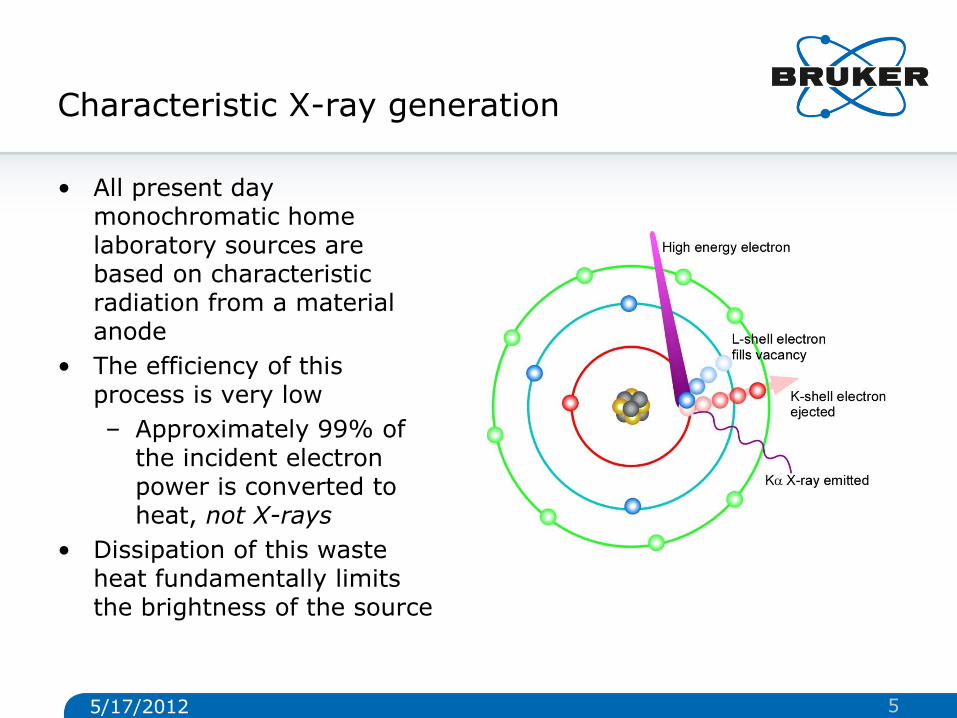
Characteristic X-ray generation
• All present day monochromatic home laboratory sources are based on characteristic radiation from a material anode
• The efficiency of this process is very low
– Approximately 99% of the incident electron power is converted to heat, not X-rays
• Dissipation of this waste heat fundamentally limits the brightness of the source
5/17/2012 5
How can one make a source brighter?
• Source performance is ultimately limited by anode melting
– There are three ways to improve performance
• Make the focus on the anode smaller
– Allows higher heat extraction efficiency
– Microfocus sources
• Rotate the anode faster
– Spreads the heat more efficiently
– Improved rotating anode
• Use a liquid metal anode
– Can’t melt (it is already molten!)
– Metal jet sources
5/17/2012 6
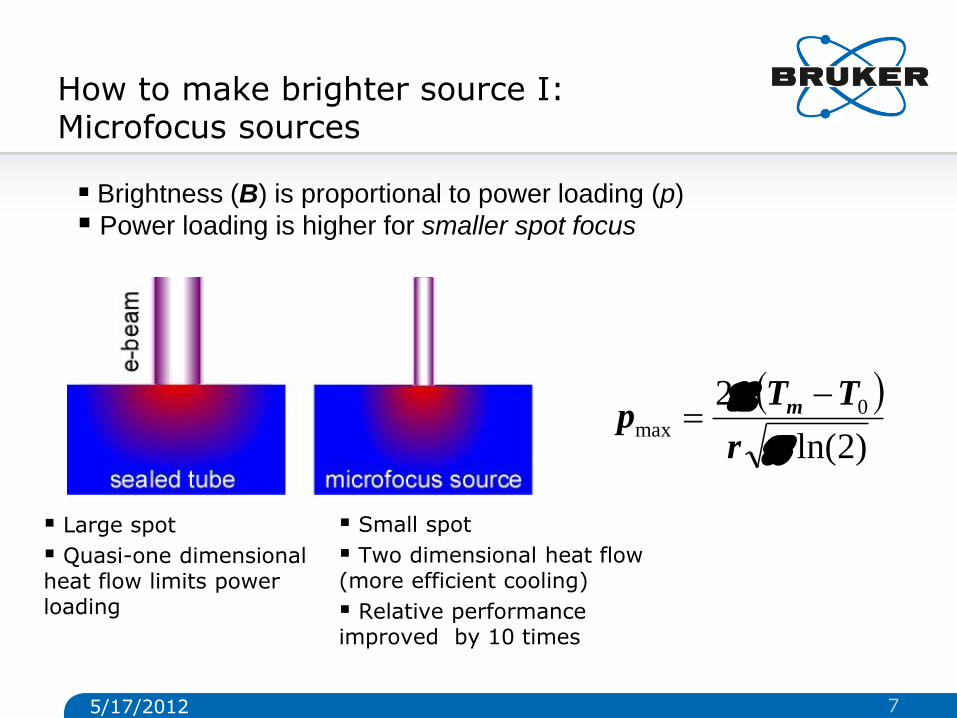
How to make brighter source I: Microfocus sources
Large spot
Quasi-one dimensional heat flow limits power loading
Small spot
Two dimensional heat flow (more efficient cooling)
Relative performance improved by 10 times
)2ln(
2 0max
r
TTp m
Brightness (B) is proportional to power loading (p)
Power loading is higher for smaller spot focus
5/17/2012 7
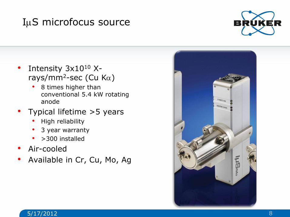
ImS microfocus source
• Intensity 3x10¹⁰ X-rays/mm2-sec (Cu Ka) • 8 times higher than
conventional 5.4 kW rotating anode
• Typical lifetime >5 years • High reliability
• 3 year warranty
• >300 installed
• Air-cooled
• Available in Cr, Cu, Mo, Ag
5/17/2012 8
17.05.2012
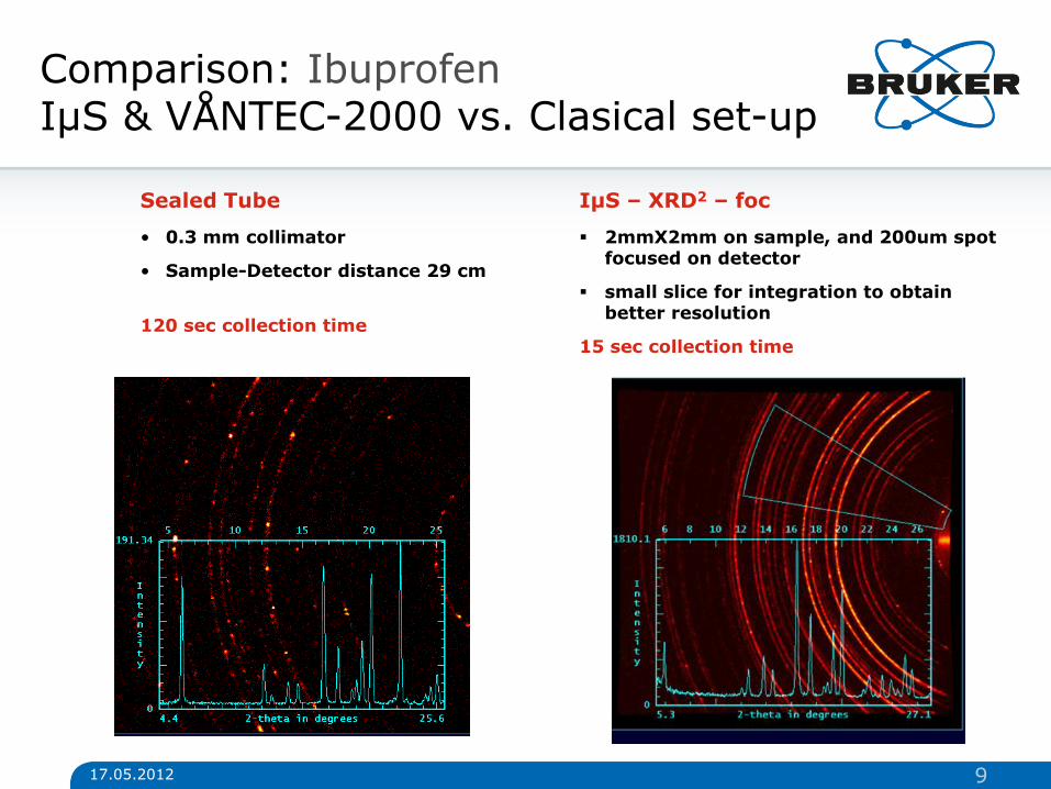
Comparison: Ibuprofen IµS & VÅNTEC-2000 vs. Clasical set-up
IµS – XRD2 – foc
2mmX2mm on sample, and 200um spot focused on detector
small slice for integration to obtain better resolution
15 sec collection time
Sealed Tube
• 0.3 mm collimator
• Sample-Detector distance 29 cm
120 sec collection time
9
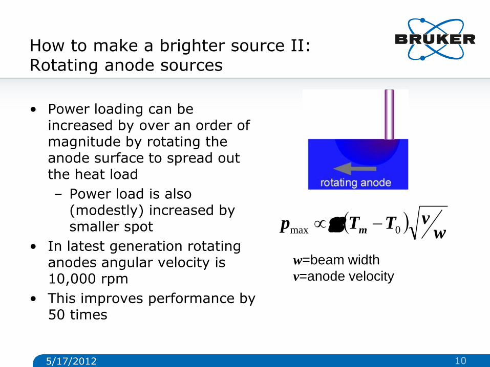
How to make a brighter source II: Rotating anode sources
• Power loading can be increased by over an order of magnitude by rotating the anode surface to spread out the heat load
– Power load is also (modestly) increased by smaller spot
• In latest generation rotating anodes angular velocity is 10,000 rpm
• This improves performance by 50 times
w
vTTp m 0max
w=beam width
v=anode velocity
5/17/2012 10
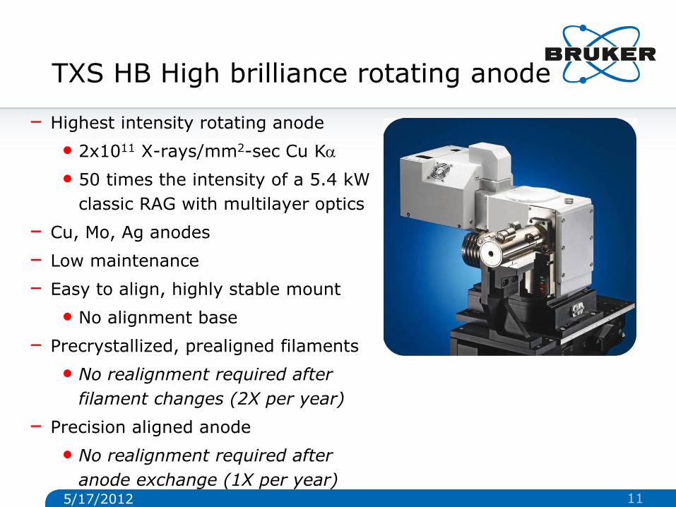
TXS HB High brilliance rotating anode
– Highest intensity rotating anode
• 2x10¹¹ X-rays/mm2-sec Cu Ka
• 50 times the intensity of a 5.4 kW
classic RAG with multilayer optics
– Cu, Mo, Ag anodes
– Low maintenance
– Easy to align, highly stable mount
• No alignment base
– Precrystallized, prealigned filaments
• No realignment required after
filament changes (2X per year)
– Precision aligned anode
• No realignment required after
anode exchange (1X per year)
5/17/2012 11
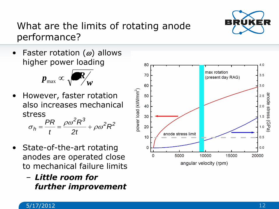
What are the limits of rotating anode performance?
• Faster rotation (w) allows higher power loading
• However, faster rotation also increases mechanical stress
• State-of-the-art rotating anodes are operated close to mechanical failure limits
– Little room for further improvement
2232
h Rt2
R
t
PRw
w
wRp wmax
5/17/2012 12
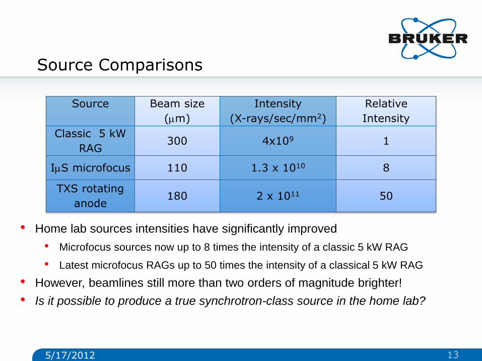
Source Comparisons
Source Beam size
(mm)
Intensity
(X-rays/sec/mm2)
Relative
Intensity
Classic 5 kW
RAG 300 4x10⁹ 1
ImS microfocus 110 1.3 x 10¹⁰ 8
TXS rotating
anode 180 2 x 10¹¹ 50
• Home lab sources intensities have significantly improved
• Microfocus sources now up to 8 times the intensity of a classic 5 kW RAG
• Latest microfocus RAGs up to 50 times the intensity of a classical 5 kW RAG
• However, beamlines still more than two orders of magnitude brighter!
• Is it possible to produce a true synchrotron-class source in the home lab?
5/17/2012 13
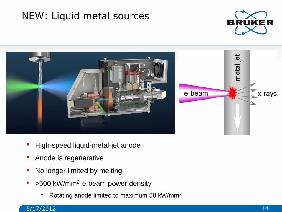
NEW: Liquid metal sources
• High-speed liquid-metal-jet anode
• Anode is regenerative
• No longer limited by melting
• >500 kW/mm2 e-beam power density
• Rotating anode limited to maximum 50 kW/mm2
5/17/2012 14
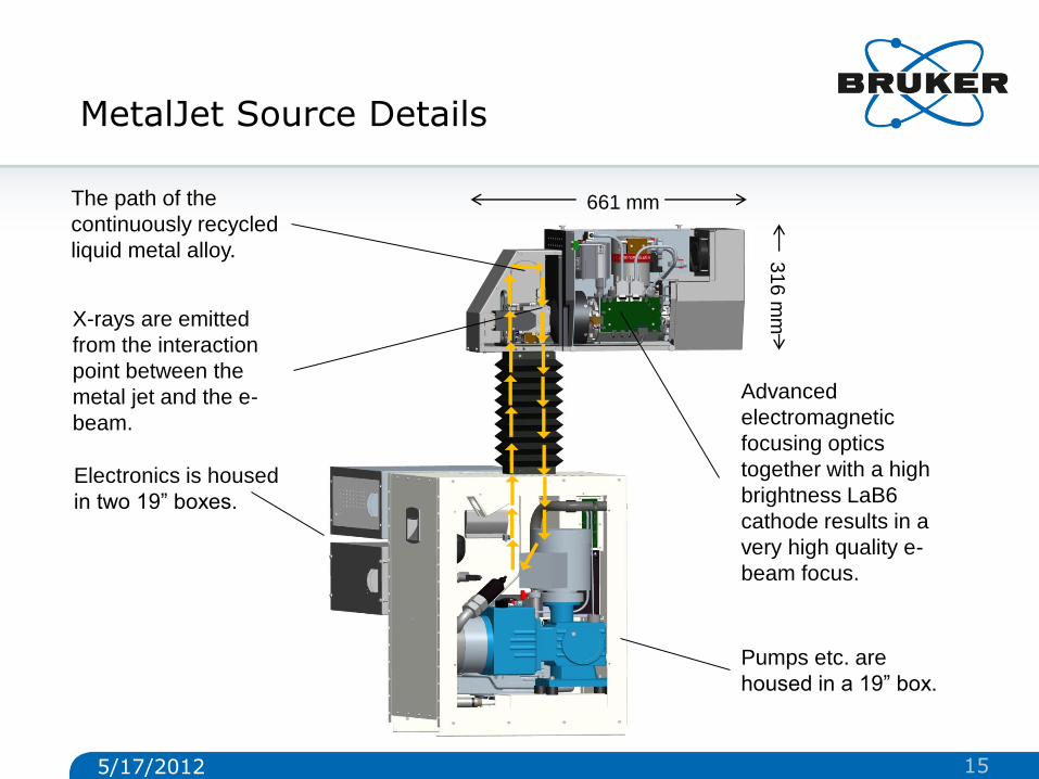
MetalJet Source Details
661 mm
31
6 m
m
Pumps etc. are
housed in a 19” box.
The path of the
continuously recycled
liquid metal alloy.
X-rays are emitted
from the interaction
point between the
metal jet and the e-
beam.
Electronics is housed
in two 19” boxes.
Advanced
electromagnetic
focusing optics
together with a high
brightness LaB6
cathode results in a
very high quality e-
beam focus.
5/17/2012 15
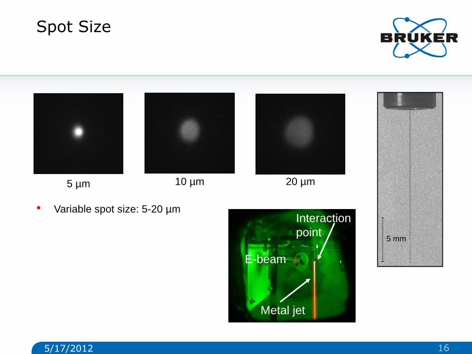
Spot Size
20 µm 10 µm 5 µm
• Variable spot size: 5-20 µm
E-beam
Interaction
point
Metal jet
5 mm
5/17/2012 16
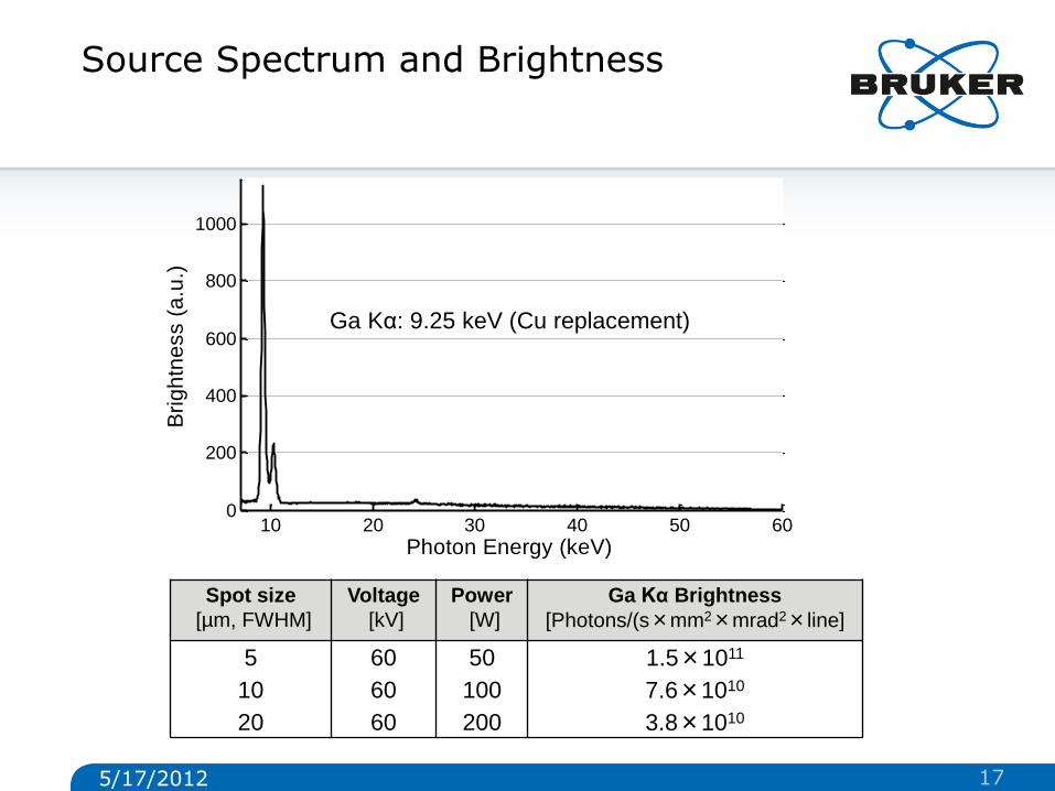
Source Spectrum and Brightness
Spot size
[µm, FWHM]
Voltage
[kV]
Power
[W]
Ga Kα Brightness
[Photons/(s×mm2×mrad2×line]
5 60 50 1.5×10¹¹
10 60 100 7.6×10¹⁰
20 60 200 3.8×10¹⁰
10 20 30 40 50 600
200
400
600
800
1000
Photon Energy (keV)
Bri
gh
tne
ss (
a.u
.)
Ga Kα: 9.25 keV (Cu replacement)
5/17/2012 17
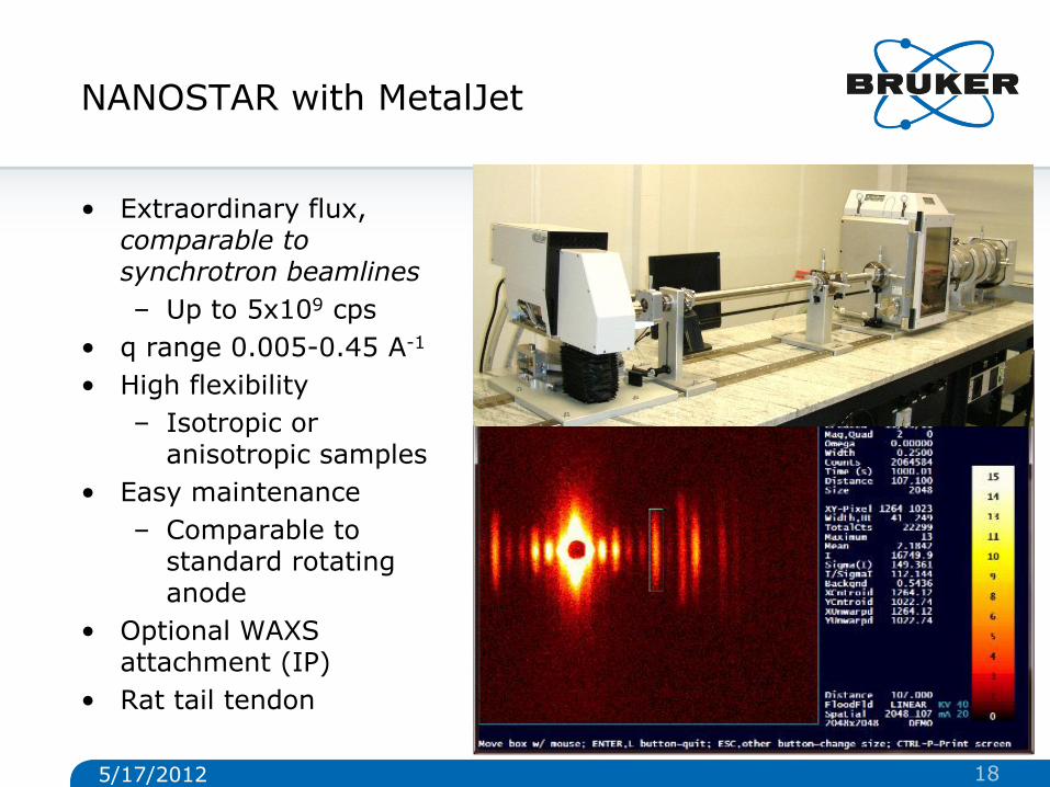
NANOSTAR with MetalJet
• Extraordinary flux, comparable to synchrotron beamlines
– Up to 5x10⁹ cps
• q range 0.005-0.45 A-1
• High flexibility
– Isotropic or anisotropic samples
• Easy maintenance
– Comparable to standard rotating anode
• Optional WAXS attachment (IP)
• Rat tail tendon
5/17/2012 18
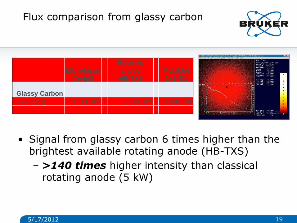
Flux comparison from glassy carbon
• Signal from glassy carbon 6 times higher than the brightest available rotating anode (HB-TXS)
– >140 times higher intensity than classical rotating anode (5 kW)
Microfocus
Cu-IµS
Rotating
anode
HB-TXS
MetalJet
JXS-D1
Glassy Carbon
Flux (cps) 1,50E+05 7,00E+05 4,00E+06
1 4.7 26.7
5/17/2012 19
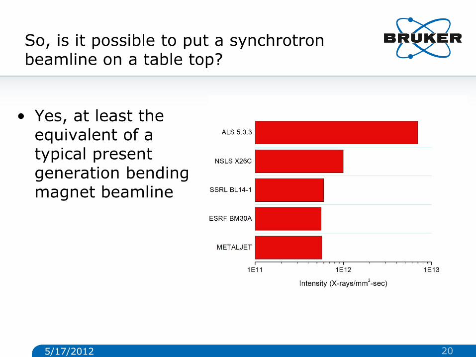
So, is it possible to put a synchrotron beamline on a table top?
• Yes, at least the equivalent of a typical present generation bending magnet beamline
5/17/2012 20
Optics and beam collimation
5/17/2012 21
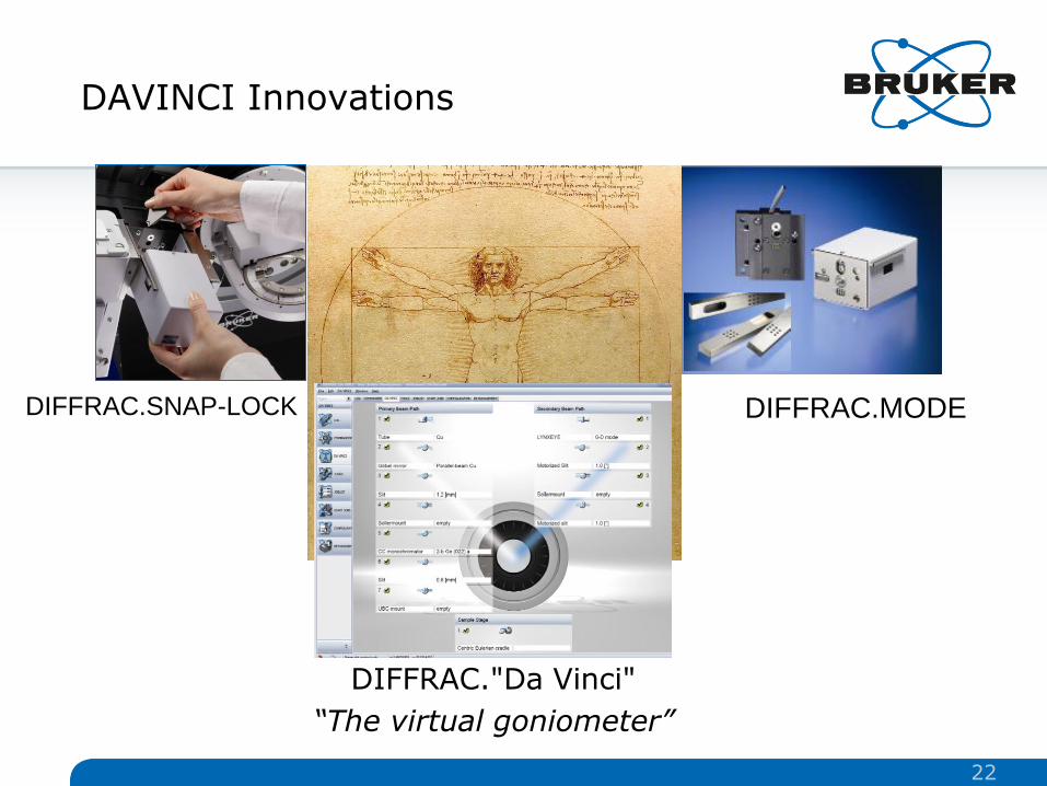
DAVINCI Innovations
DIFFRAC."Da Vinci"
“The virtual goniometer”
DIFFRAC.MODE DIFFRAC.SNAP-LOCK
22
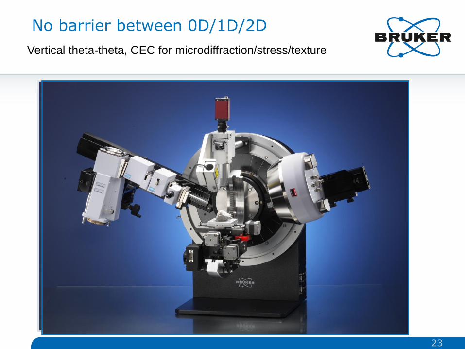
No barrier between 0D/1D/2D
Vertical theta-theta, CEC for microdiffraction/stress/texture
23
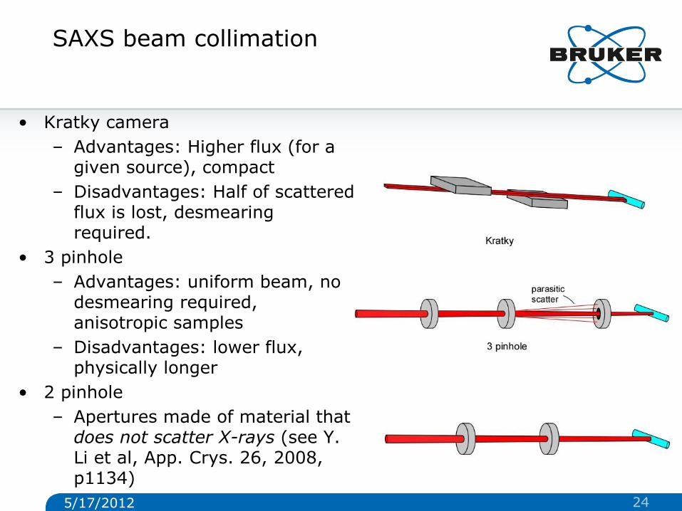
SAXS beam collimation
• Kratky camera
– Advantages: Higher flux (for a given source), compact
– Disadvantages: Half of scattered flux is lost, desmearing required.
• 3 pinhole
– Advantages: uniform beam, no desmearing required, anisotropic samples
– Disadvantages: lower flux, physically longer
• 2 pinhole
– Apertures made of material that does not scatter X-rays (see Y. Li et al, App. Crys. 26, 2008, p1134)
5/17/2012 24
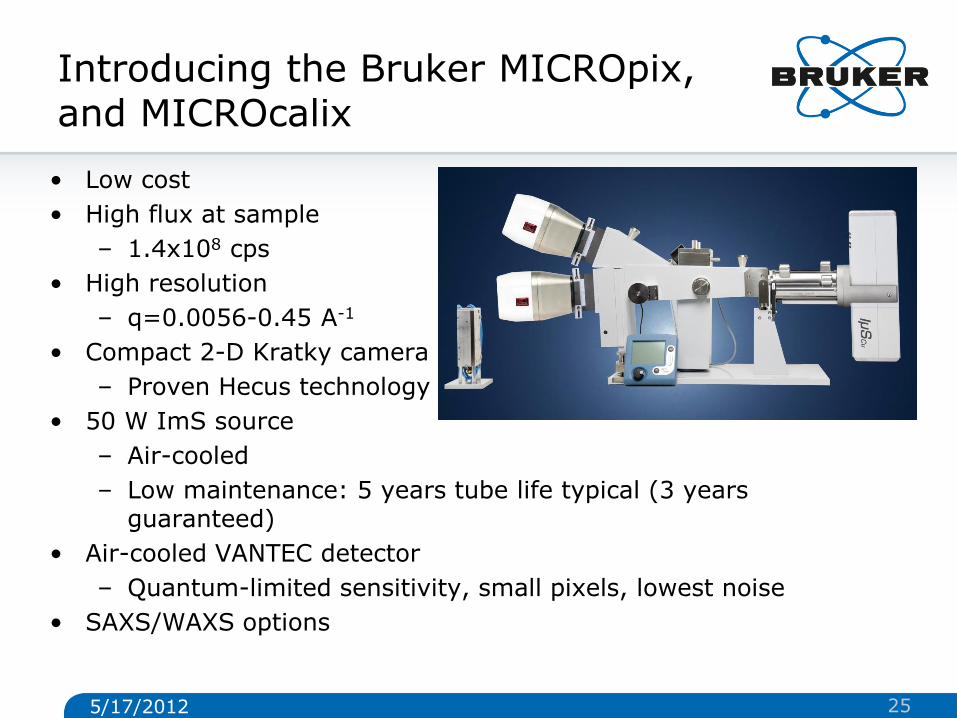
Introducing the Bruker MICROpix, and MICROcalix
• Low cost
• High flux at sample
– 1.4x10⁸ cps
• High resolution
– q=0.0056-0.45 A-1
• Compact 2-D Kratky camera
– Proven Hecus technology
• 50 W ImS source
– Air-cooled
– Low maintenance: 5 years tube life typical (3 years guaranteed)
• Air-cooled VANTEC detector
– Quantum-limited sensitivity, small pixels, lowest noise
• SAXS/WAXS options
5/17/2012 25
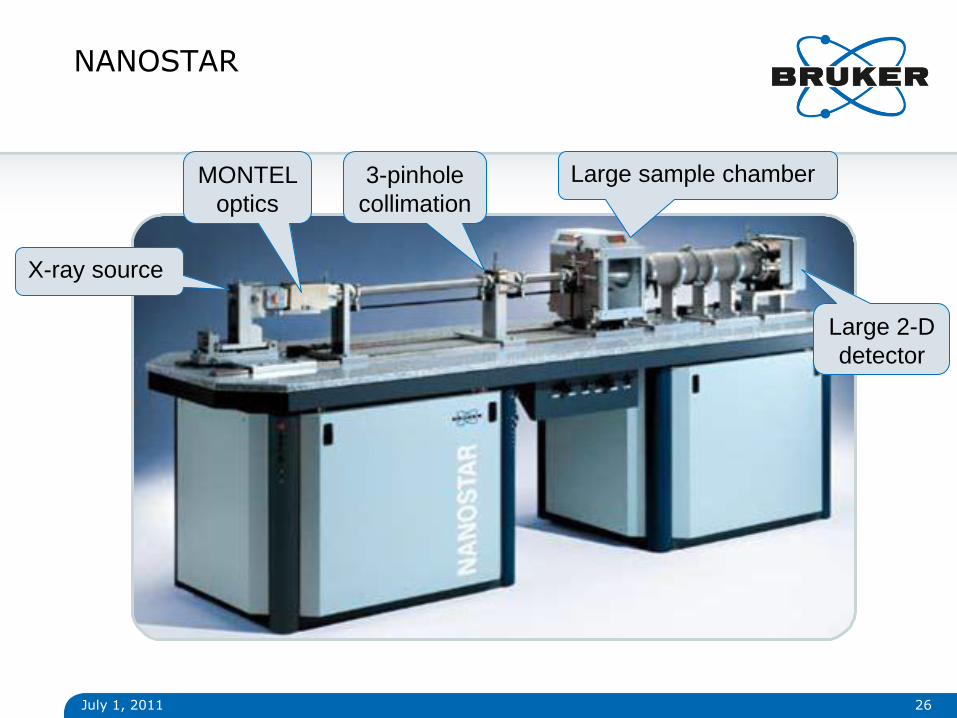
NANOSTAR
July 1, 2011 26
X-ray source
MONTEL
optics
3-pinhole
collimation
Large sample chamber
Large 2-D
detector
Detector
5/17/2012 27
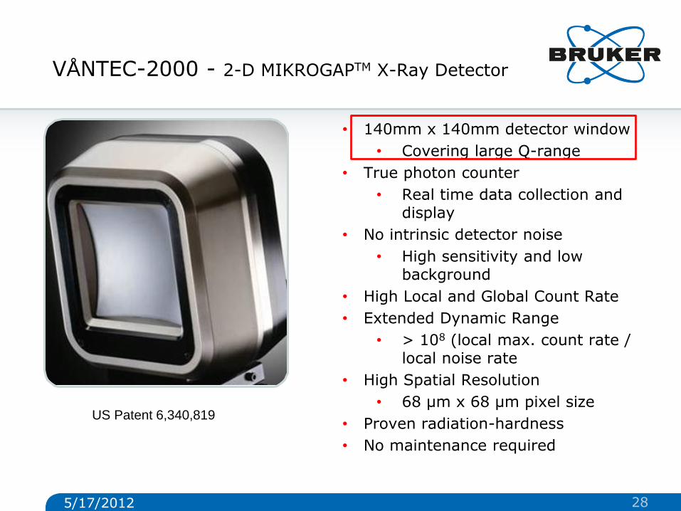
VÅNTEC-2000 - 2-D MIKROGAPTM X-Ray Detector
• 140mm x 140mm detector window
• Covering large Q-range
• True photon counter
• Real time data collection and display
• No intrinsic detector noise
• High sensitivity and low background
• High Local and Global Count Rate
• Extended Dynamic Range
• > 108 (local max. count rate / local noise rate
• High Spatial Resolution
• 68 µm x 68 µm pixel size
• Proven radiation-hardness
• No maintenance required
US Patent 6,340,819
5/17/2012 28

• A 2-D detector is essential for measuring anisotropic data, but also
enhances sensitivity for isotropic data
• Data evaluation is done on integrated 1-D data
July 1, 2011
2-D SAXS/WAXS Typical Data
2-D SAXS pattern of collagen fibrils 2-D WAXS pattern of Al2O3
29
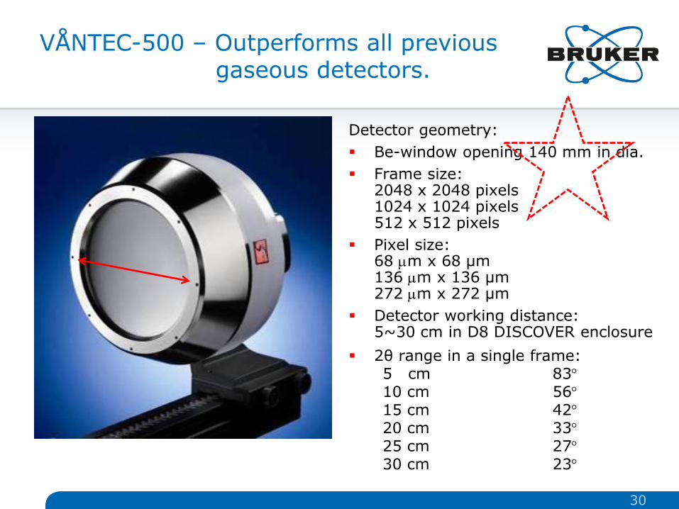
Detector geometry:
Be-window opening 140 mm in dia.
Frame size: 2048 x 2048 pixels 1024 x 1024 pixels 512 x 512 pixels
Pixel size: 68 mm x 68 µm 136 mm x 136 µm 272 mm x 272 µm
Detector working distance: 5~30 cm in D8 DISCOVER enclosure
2θ range in a single frame: 5 cm 83 10 cm 56 15 cm 42 20 cm 33 25 cm 27 30 cm 23
VÅNTEC-500 – Outperforms all previous gaseous detectors.
30
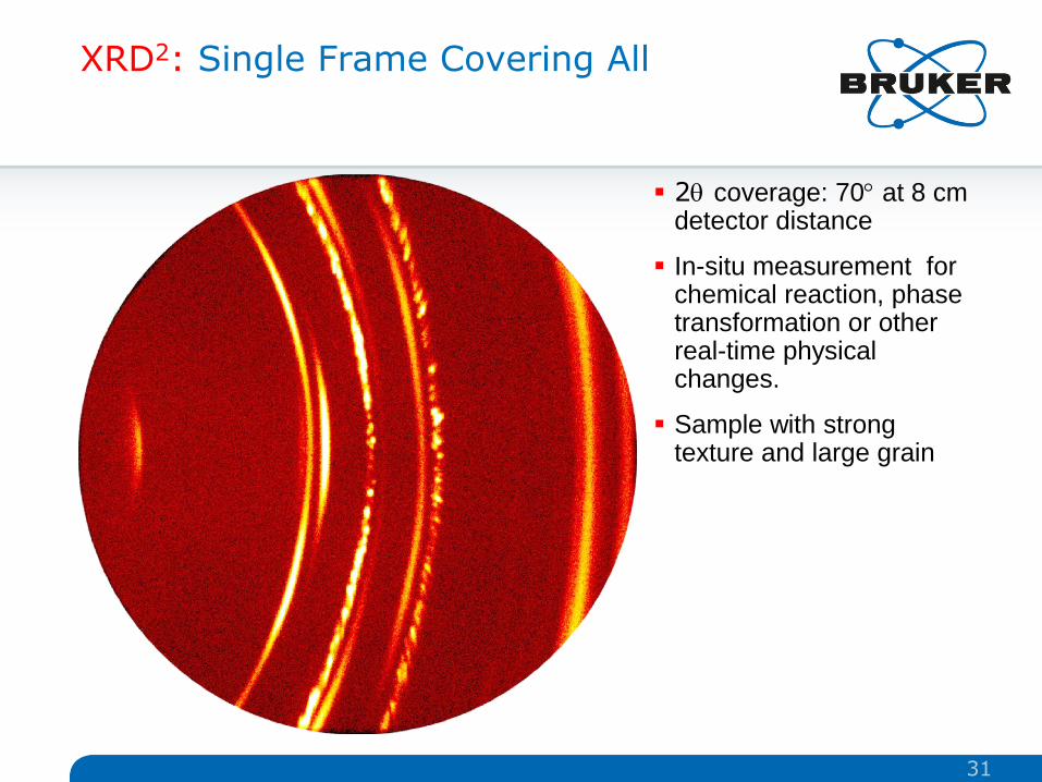
XRD2: Single Frame Covering All
2 coverage: 70 at 8 cm detector distance
In-situ measurement for chemical reaction, phase transformation or other real-time physical changes.
Sample with strong texture and large grain
31
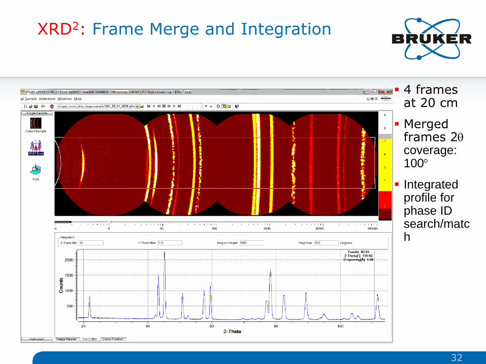
XRD2: Frame Merge and Integration
4 frames at 20 cm
Merged frames 2 coverage: 100
Integrated profile for phase ID search/match
32

The D8 DISCOVER with DAVINCI VÅNTEC-500 for texture measurement
Steel can
(200) & (110) rings
Intensity variation during
scan
33
17.05.2012
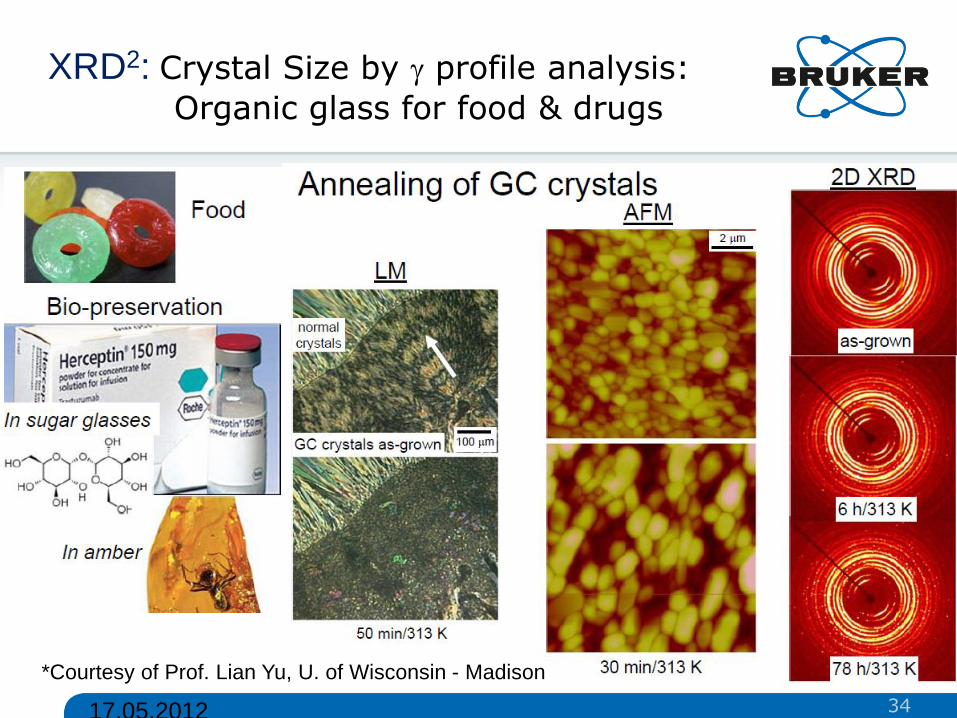
XRD2: Crystal Size by profile analysis:
Organic glass for food & drugs
*Courtesy of Prof. Lian Yu, U. of Wisconsin - Madison
34

17.05.2012
XRD2: Crystal Size by profile analysis:
Acetaminophen powder
The spotty diffraction ring is due to the large crystallites compared to the sampling volume (beam size).
The number of spots on the ring is determined by crystallite size, instrumental window (-range), multiplicity of the crystal plane, and effective diffraction volume.
The size of jelly beans and candy bin determines how many you can fill.
35
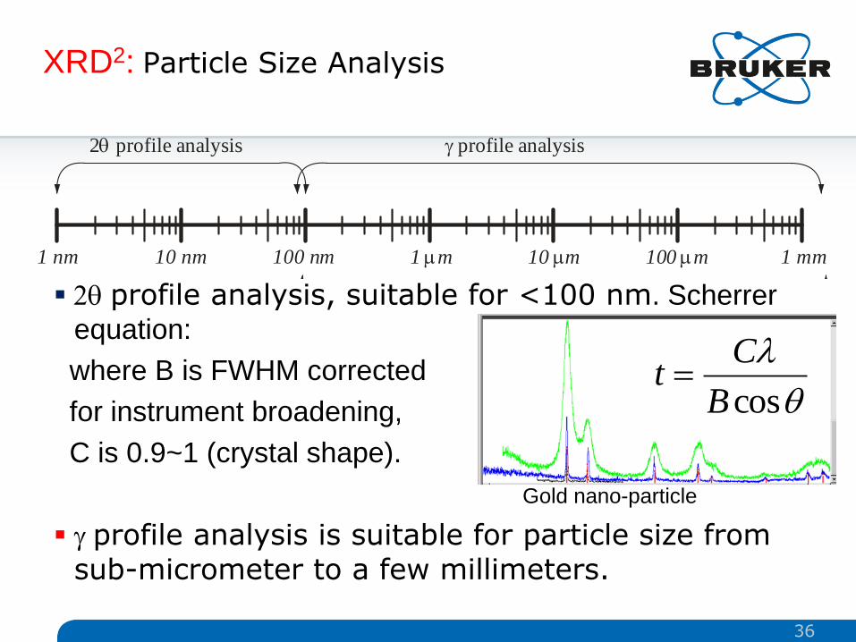
XRD2: Particle Size Analysis
1 nm 10 nm 100 nm 1 mm 10 mm 100 mm 1 mm
2 profile analysis profile analysis
particle size range in pharmaceutical systems
2 profile analysis, suitable for <100 nm. Scherrer
equation:
where B is FWHM corrected
for instrument broadening,
C is 0.9~1 (crystal shape).
profile analysis is suitable for particle size from sub-micrometer to a few millimeters.
cosB
Ct
Gold nano-particle
36
© Copyright Bruker Corporation. All rights reserved.
Innovation with Integrity
Copyright © 2011 Bruker Corporation. All rights reserved. www.bruker.com 17. Mai 2012 37 17. Mai 2012 37 © Copyright Bruker Corporation. All rights reserved
Thanks for your attention