network-on-chip (1/2) ben abdallah, abderazek the university of aizu e-mail: [email protected] 1...
TRANSCRIPT

Network-on-Chip(1/2)
Ben Abdallah, Abderazek
The University of Aizu
E-mail: [email protected]
1KUST University, March 2011

Part 1Part 1Application RequirementsApplication Requirements
Network on Chip: A paradigm Shift in Network on Chip: A paradigm Shift in
VLSIVLSI
Critical problems addressed by NoCCritical problems addressed by NoC
Traffic abstractions Traffic abstractions
Data AbstractionData Abstraction
Network delay modelingNetwork delay modeling
2

Application Requirements
Signal processingo Hard real timeo Very regular loado High quality
Typically on DSPs
Media processingo Hard real timeo Irregular loado High quality
SoC/media processors
Multimediao Soft real timeo Irregular loado Limited quality
PC/desktop
Very challenging!
3

What the Internet Needs?
• High processing power• Support wire speed• Programmable• Scalable• Specially for network applications
Increasing Huge Amount of Packets
&Routing,
Packet Classification, Encryption, QoS, New Applications
and Protocols, etc…..
General Purpose RISC (not capable enough)
ASIC(large,
expensive to develop, not flexible)
4
MCSoC

Example - Network Processor (NP)
5
IBM PowerNP

Example - Network Processor (NP)
6
NP can be applied in various network layers and applications Traditional apps – forwarding,
classification Advanced apps – transcoding, URL-
based switching, security etc. New apps

Telecommunication Systems and NoC Paradigm
The trend nowadays is to integrate telecommunication system on complex multicore SoC (MCSoC): Network processors, Multimedia hubs ,and base-band telecom circuits
These applications have tight time-to-market and performance constraints
7

Telecommunication Systems and NoC Paradigm
Telecommunication multicore SoC is composed of 4 kinds of components: Software tasks Processors executing software Specific hardware cores, and Global on-chip communication network
8

Telecommunication Systems and NoC Paradigm
Telecommunication multicore SoC is composed of 4 kinds of components: 1. Software tasks, 2. Processors executing software, 3. Specific hardware cores , and 4. Global on-chip communication
network
9
This is the most challenging part

Technology & Architecture Trends
Technology trends: Vast transistor budgets Relatively poor interconnect scaling Need to manage complexity and power Build flexible designs (multi-/general-
purpose)Architectural trends:
Go parallel !
10

Operation Delay(.13mico)
Delay(.05micro)
32-bit ALU Operation 650ps 250ps
32-bit Register read 325ps 125ps
Read 32-bit from 8KB RAM 780ps 300ps
Transfer 32-bit across chip (10mm)
1400ps 2300ps
Transfer 32-bit across chip (200mm)
2800ps 4600ps
2:1 global on-chip communication to operation delay 9:1 in 2010
Ref: W.J. Dally HPCA Panel presentation 2002
Wire Delay vs. Logic Delay
11

Information transfer is inherently unreliable at the electrical level, due to: Timing errors Cross-talk Electro-magnetic interference (EMI) Soft errors
The problem will get increasingly worse as technology scales down
Communication Reliability
12

Evolution of on-chip Communication
13

Traditional SoC Nightmare
Variety of dedicated interfaces Design and verification complexity Unpredictable performance Many underutilized wires
14
DMA CPU DSP
Bridge
IO IO IOC
A
BPeripheral Bus
CPU Bus
Control signals

Network on Chip: A paradigm Shift in VLSI
15
s
s
s
s
s s
s
s
Module
Module
s
Module
From: Dedicated signal wires To: Shared network
Point- To-point Link
Network switch
Computing Module

Network on Chip: A paradigm Shift in VLSI
NINI
DRAMDRAM
switchswitch
NINI
CPUCPU
AccelAccel
NINI
switchswitch
switchswitch
switchswitch
NoCNoC
switchswitch
switchswitch
NINI
DRAMDRAM
CoprocCoproc
I/OI/O
NINI
NINI
NINI
NINI
NINI
NINI
NINI
NINI
DSPDSP
DMADMA
MPEGMPEG
DMADMA
EthntEthnt
EthntEthnt
16

NoC Essential
Communication by packets of bits
Routing of packets through several hops, via switches
Efficient sharing of wires
Parallelism
17
s
s
s
s
s s
s
s
Module
Module
s
Module

NoC Operation Example
1.1. CPU requestCPU request
2.2. Packetization and trans.Packetization and trans.
3.3. RoutingRouting
4.4. Receipt and unpacketization (AHB, Receipt and unpacketization (AHB, OCP, ... pinout)OCP, ... pinout)
5.5. Device response (if needed)Device response (if needed)
6.6. Packetization and transmissionPacketization and transmission
7.7. RoutingRouting
8.8. Receipt and unpacketizationReceipt and unpacketization
CPUCPUCPUCPU
I/OI/O
18

Characteristics of a Paradigm Shift
Solves a critical problem Step-up in abstraction Design is affected:
Design becomes more restricted New tools The changes enable higher complexity
and capacity Jump in design productivity
19

Characteristics of a Paradigm shift
Solves a critical problem Step-up in abstraction Design is affected:
Design becomes more restricted New tools The changes enable higher complexity
and capacity Jump in design productivity
20

Origins of the NoC Concept The idea was talked about in the 90’s, but
actual research came in the new illenium. Some well-known early publications: Guerrier and Greiner (2000) “A generic architecture
for on-chip packet-switched interconnections” Hemani et al. (2000) “Network on chip: An
architecture for billion transistor era” Dally and Towles (2001) “Route packets, not wires:
on-chip interconnection networks” Wingard (2001) “MicroNetwork-based integration of
SoCs” Rijpkema, Goossens and Wielage (2001) “A router
architecture for networks on silicon” De Micheli and Benini (2002) “Networks on chip: A
new paradigm for systems on chip design”21

Don't we already know how to design interconnection
networks?
Many existing network topologies, router designs and theory has already been developed for high end supercomputers and telecom switches
Yes, and we'll cover some of this material, but the trade-offs on-chip lead to very different designs!!
2222

Critical problems addressed by NoC
23
1) Global interconnect design problem:delay, power, noise, scalability, reliability
2) System integrationproductivity problem
3) Chip Multi Processors(key to power-efficient computing

1(a): NoC and Global wire delay
24
Long wire delay is dominated by Resistance
Add repeaters
Repeaters become latches (with clock frequency scaling)
Latches evolve to NoC routers
NoC Router
NoC Router
NoC Router

1(b): Wire design for NoC
25
NoC links:
Regular Point-to-point (no fanout tree) Can use transmission-line layout Well-defined current return path
Can be optimized for
noise /speed/power ? Low swing, current mode, ….

1(c): NoC Scalability
26
NoC:O(n)
O(n)
Point –to-Point
O(n^2 √n)
O(n √n)
Simple BusO(n^3 √n)
O(n√n)
Segmented Bus:O(n^2 √n)
O(n√n)
For Same Performance, compare the wire area and power

1(d): NoC and Communication Reliability
27
Router
UMODEM
UMODEM
UMODEM
UMODEM
Router
UMODEM
UMODEM
UMODEM
UMODEM
Router
…
Error correction
Synchronization
ISI reduction
Parallel to Serial Convertor
Modulation
Link Interface
Interconnect
Input buffer
m
n
Fault tolerance & error correction
A. Morgenshtein, E. Bolotin, I. Cidon, A. Kolodny, R. Ginosar, “Micro-modem – reliability solution for NOC communications”, ICECS 2004

1(e): NoC and GALS
Modules in NoC System use different clocks May use different voltages
NoC can take care of synchronization
NoC design may be asynchronous No waste of power when the links and
routers are idle
28

2: NoC and Engineering Productivity
NoC eliminates ad-hoc global wire engineering
NoC separates computation from communication NoC supports modularity and reuse of
cores NoC is a platform for system
integration, debugging and testing
29

3: NoC and Multicore
Uniprocessors cannot provide Power-efficient performance growth Interconnect dominates dynamic power Global wire delay doesn’t scale Instruction-level parallelism is limited
30
Gate
Inte
rcon
nect
Diff.
Uniprocessordynamic power
(Magen et al., SLIP 200

3: NoC and Multicore
Power-efficiency requires many parallel local computations Chip Multi Processors (Multicore) Thread-Level Parallelism (TLP)
31
Uniprocessor Performance
Die Area (or Power)

3: NoC and Multicore Uniprocessors cannot provide Power-efficient
performance growth Interconnect dominates dynamic power Global wire delay doesn’t scale Instruction-level parallelism is limited
Power-efficiency requires many parallel local computations Chip Multi Processors (CMP) Thread-Level Parallelism (TLP)
Network is a natural choice for CMP!
32

3: NoC and Multicore Uniprocessors cannot provide Power-efficient
performance growth Interconnect dominates dynamic power Global wire delay doesn’t scale Instruction-level parallelism is limited
Power-efficiency requires many parallel local computations Chip Multi Processors (CMP) Thread-Level Parallelism (TLP)
Network is a natural choice for CMP!
33
Network is a
natural choice
for Multico
re

Why Now is the time for NoC?
34
Difficulty of DSM wire design
Productivity pressure
Multicore

Traffic AbstractionsTraffic model are generally captured from
actual traces of functional simulationA statically distribution is often assumed
for message
35
PE1 PE2PE3
PE4PE12
PE11
PE5
PE9PE7
PE8 PE6
PE10
Flow Bandwidth Packet size Latency1 ->10 400kb/s 1kb 5ns2->10 1.8Mb/s 3kb 12ns1->4 230kb/s 2kb 6ns4->10 50kb/s 1kb 3ns4->5 300kb/s 3kb 4ns3->10 34kb/s 0.5kb 15ns5->10 400kb/s 1kb 4ns6->10 699kb/s 2kb 1ns8->10 300kb/s 3kb 12ns9->8 1.8mb/s 5kb 7ns9->10 200kb/s 5kb 10ns7->10 200kb/s 3kb 12ns11->10 300kb/s 4kb 10ns12->10 500kb/s 5kb 12ns

Data Abstractions
36

Layers of Abstraction in Network Modeling
Software layers Application, OS
Network & transport layers Network topology e.g. crossbar, ring, mesh, torus, fat
tree,… Switching Circuit / packet switching(SAF, VCT),
wormhole Addressing Logical/physical, source/destination, flow,
transaction Routing Static/dynamic, distributed/source, deadlock
avoidance Quality of Service e.g. guaranteed-throughput,
best-effort Congestion control, end-to-end flow control
37

Layers of Abstraction in Network Modeling
Data link layer Flow control (handshake) Handling of contention Correction of transmission errors
Physical layer Wires, drivers, receivers, repeaters, signaling,
circuits,..
38

How to Select Architecture ?
Architecture choices depends on system needs.
39
ASIC
FPGA
ASSP
CMP/Multicor
e
ReconfigurationRate
During run time
At boot time
At design time
Single application General purpose or Embedded systems
Flexibility

How to Select Architecture ?
Architecture choices depends on system needs
40
ASIC
FPGA
ASSP
CMP/Multicor
e
ReconfigurationRate
During run time
At boot time
At design time
Single application General purpose or Embedded systems
Flexibility
A large range of solutions!

Example: OASIS NoC
41
A. Ben Abdallah, and M. Sowa, "Basic Network-on-Chip Interconnection for Future Gigascale MCSoCs Applications: Communication and Computation Orthogonalization", (TJASSST), Dec. 4-9th, 2006.

Perspective 1: NoC vs. Bus
Aggregate bandwidth grows
Link speed unaffected by N Concurrent spatial reuse Pipelining is built-in Distributed arbitration Separate abstraction layers
However: No performance
guarantee Extra delay in routers Area and power
overhead? Modules need NI Unfamiliar methodology 42
Bandwidth is shared Speed goes down as N grows No concurrency Pipelining is tough Central arbitration No layers of abstraction (communication and computation are coupled)
However: Fairly simple and familiar
NoC Bus

Perspective 2: NoC vs. Off-chip Networks
Cost is in the links Latency is tolerable Traffic/applications
unknown Changes at runtime Adherence to
networking standards
43
Sensitive to cost: area power
Wires are relatively cheap
Latency is critical
Traffic may be known a-
priori
Design time specialization
Custom NoCs are possible
Off-Chip NetworksNoC
VLSI CAD Problems
Application mapping Floorplanning / placement Routing Buffer sizing Timing closure Simulation Testing
44

VLSI CAD Problems in NoCApplication mapping (map tasks to cores) Floorplanning / placement (within the
network) Routing (of messages) Buffer sizing (size of FIFO queues in the
routers)Simulation (Network simulation,
traffic/delay/power modeling)Other NoC design problems (topology
synthesis, switching, virtual channels, arbitration, flow control,……)
45

Typical NoC Design Flow
46
Place Modules
Determine routing and adjust link capacities

Timing Closure in NoC
47
Define inter-
module traffic
Place modules
Increase link
capacities
QoS satisfie
d ?
No
Yes
Finish
Too long capacity results in poor QoS Too high capacity wastes area Uniform link capacities are a waste in ASIP system

NoC Design RequirementsHigh-performance interconnect
High-throughput, latency, power, areaComplex functionality (performance
again) Support for virtual-channels QoS
Synchronization Reliability, high-throughput, low-latency
48

Part 2
Routing algorithms Routing algorithms Flow control schemes Flow control schemes
Clocking Schemes Clocking Schemes QoS QoS
Putting it all together Putting it all together
49

NoC Routing Algorithms
They must prevent deadlock, livelock, and starvation
Choice of a routing algorithm depends on: Minimizing power required for routing Minimizing logic and routing tables
50
Responsible for correctly and efficiently routing packets or circuits from source to destination

Routing Algorithm Routing Algorithm ClassificationsClassifications3 different criteria:
Where the routing decision are taken ? Source routing Distributed routing
How a path is defined ? Static (deterministic) Adaptive
The path length Minimal Nonminimal
51
NoC Routing-Table
The Routing Table determines for each PE the route via which it will send packets to other PEs
The routing table directly influences traffic in the NoC
Here we can also distinguish between 2 methods: Static routing Dynamic (adaptive) routing
52

Static Routing
The Routing Table is constant. The route is embedded in the
packet header and the routers simply forward the packet to the direction indicated by the header
The routers are passive in their addressing of packets (simple routers)
53

Dynamic RoutingThe routing table can change
dynamically during operation Logically, a route is changed when
it becomes slow due to other trafficPossibly out-of-order arrival of
packets.Usually requires more virtual
channels
54

Dynamic Routing
More resources needed to monitor state of the network
55
3 2 1 2 1 3
X
Adaptive routing scheme
Packet Packet

Routing Algorithms Requirements
Routing algorithm must ensure freedom from deadlocks e.g. cyclic dependency shown below
Routing algorithm must ensure freedom from livelocks and starvation
56

Flow Control Schemes -STALL/GO
Low overhead schemeRequires only two control wires
One going forward and signaling data availability
the other going backward and signaling either a condition of buffers filled (STALL) or of buffers free (GO)
57

Repeaters are two-entry FIFOsNo retransmission allowed
SS RR
FLITFLIT
REQREQ
STALLSTALL
FLITFLIT
REQREQ
STALLSTALL
FLITFLIT
REQREQ
STALLSTALL
Flow Control Schemes -STALL/GO
58

Flow Control Schemes - T-Error
More aggressive scheme that can detect faults by making use of a second delayed clock at every
buffer stageDelayed clock re-samples input data to detect any
inconsistencies
59

Flow Control Schemes - Flow Control Schemes - ACK/NACKACK/NACK
When flits are sent on a link, a local copy is kept in a buffer by sender
When ACK received by sender, it deletes copy of flit from its local buffer
When NACK is received, sender rewinds its output queue and starts resending flits, starting from the corrupted one
60

Repeaters are pure registersBuffering and retransmission logic in
the sender
Flow Control Schemes - ACK/NACK
SS RR
FLITFLIT
REQREQ
ACKACK
FLITFLIT
REQREQ
ACKACK
FLITFLIT
REQREQ
ACKACK
61

ACK/NACK propagationMemory deallocation
NACK
RetransmissionGo-back-N
Transmission
Example: ACK/NACK Flow Control
ACK and buffering
62

Clocking SchemesFully synchronous
Single global clock is distributed to synchronize entire chiphard to achieve in practice, due to process variations and
clock skew
Mesochronous Local clocks are derived from a global clock Not sensitive to clock skew
Pleisochronous clock signals are produced locally
Asynchronous clocks do not have to be present at all
63
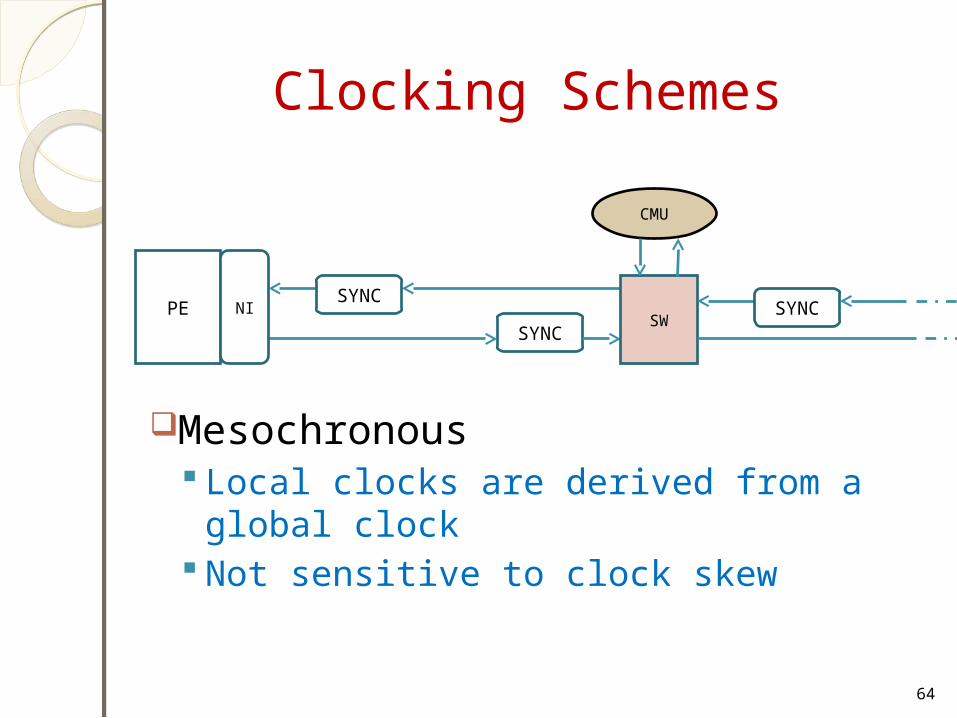
Clocking Schemes
Mesochronous Local clocks are derived from a global
clock Not sensitive to clock skew
64
PESYNC
NISYNC
SW
CMU
SYNC
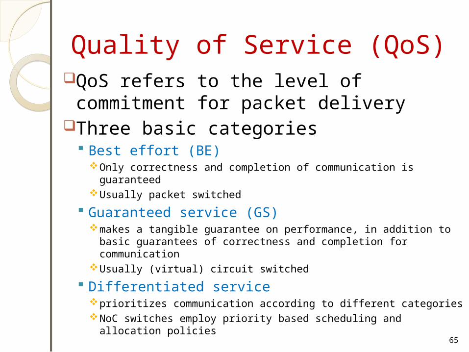
Quality of Service (QoS)QoS refers to the level of commitment
for packet deliveryThree basic categories
Best effort (BE) Only correctness and completion of communication is
guaranteedUsually packet switched
Guaranteed service (GS)makes a tangible guarantee on performance, in addition to
basic guarantees of correctness and completion for communication
Usually (virtual) circuit switched
Differentiated serviceprioritizes communication according to different categoriesNoC switches employ priority based scheduling and allocation
policies65

Putting it all Together
66

Packet Format
67
Message, Packet and Flit Formats

Size: Phit, Flit, Packet
There are no fixed rules for the size of phits, flits and packets Message: arbitrarily long Packets: restricted maximum length
Typical values Phits: 1 bit to 64 bits Flits: 16 bits to 512 bits Packets: 128 bits to 1024 bits
68

NoC Queuing Schemes
69
1 2 3 4
1 3 2 4
1 2 4 3
4 2 3 1
Output 0
Output 1
Output 2
Output 3
Input 1
Input 0
Input 3
Input 3
HOL blocking problem in Input Queuing

Flow Control Schemes -
70
Transmitter
Stop
Packet
Packetenable Receiver
Stop & Go Flow Control
Go threshold
Stop threshold
Buffer is occupied
Buffer is released
Minimum Buffer Size = Flit Size x ( Roverhead + Soverhead + 2 x Link delay)
Roverhead: the required time to issue the stop signal at the received router
Soverhead : the required time to stop sending a flit as soon as the stop signal is received

Flow Control Schemes - -
71
Transmitter
Stop
Packetenable Receiver
Credit Based (CB) Flow Control
Stop threshold
Buffer is released
Credit is decremented
A flit is transferred
Credit is incremented
CB makes the best use of channel buffers
Can be implemented regardless of the link length of the sender & receiver overhead

Queue and Buffer DesignEffective bandwidth of Data link later is
influenced by the traffic pattern and Q size
Q Buffers consume most of the area and power among all NoC building blocks.
72
D Q D QD Q D QD Q
sh shsh shsh
Packet out
Intermediate Empty Bubble
Packet IN
Conventional Shift Register Method

Network InterfaceDifferent interface shall be connected to
the networkThe network uses a specific protocol and all
traffic on the network has to comply to the format of this protocol
73

Network Interface
Open Core Protocol (OCP) Network Protocol
coreNetwork
Interface Network
PAYLOAD HEADERTAIL
FLITFLITFLIT…FLIT
Transmit– Access routing tables– Assemble packets– Split into flits
Receive– Synchronize– Drop routing information 74
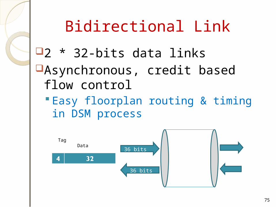
Bidirectional Link
2 * 32-bits data linksAsynchronous, credit based flow
control Easy floorplan routing & timing in DSM
process
75
36 bits
36 bits
Tag Data

Router Design
76

Router Design with Cross Point
77
OQ1 OQ1 OQ1 OQ1Output Queues (Optional)
1 2 3 4
IQ1
IQ1
IQ1
IQ1
Switch Fabric
Input Queues
Output port Schedulerrequest
grant
4-bit
Grant
ph-1:0
phit-1:0

Scheduler Design
78
PPE
n Grant
AnyGnt
INCIENC
log n
Simple PE
Simple PE
T.E.
anyGnt
n
n
Gnt
n
Termo encoder
log n
P_enc
n
Req
n
Round-roubin Algorithm circuits with 2 priority

Phit Size DeterminationThe phit size is the bit width of a link and
determines the switch area
79
PE
NI
phit size = packet size/SERR
Operation freq = SERR* fNORM
Switch
Buffers
PE
NI
phit size = packet size
Operation freq = fNORM
Switch
BuffersSER/DES

Part 3
Network TopologyNetwork-on-Chip topology
Direct topologyIndirect topology
Irregular topology
80

NoC Topology
Adopted from large-scale networks and parallel computing
Topology classifications: Direct topologies Indirect topologies
81
The connection map between PEs
Network Topology
A good topology allows to fulfill the requirements of the traffic at reasonable costs
Network topology can be compared with a network of roads
82

Direct Topology
Each switch (SW) is connected to a single PE
As the # of nodes in the system increases, the total bandwidth also increases
83
1 PE is connected to only a single SW
PE
PE PE
PE
SW
SW SW
SW

Direct Topology - Mesh
2D mesh is most popular All links have the same length
Eases physical design
Area grows linearly with the the # of nodes
844x4 Mesh

Direct Topology - Torus and Folded Torus
85
PE
R
PE
R
PE
R
PE
R
PE
R
PE
R
PE
R
PE
R
PE
R
PE
R
PE
R
PE
R
PE
R
PE
R
PE
R
PE
R
PE
RPE
RPE
RPE
RPE
RPE
RPE
RPE
R
PE
RPE
RPE
RPE
RPE
RPE
RPE
RPE
R
Folded TorusTorus
Overcomes the long link limitation of a 2-D torus
Links have the same size
Similar to a regular Mesh
Excessive delay problem due to long-end-around connection

Direct Topology - Octagon
Messages being sent between any 2 nodes require at most two hops
More octagons can be tiled together to accommodate larger designs
86
PE
PE
PE
PE PE
PE
PE
PE
SW

Indirect Topology
Fat tree Nodes are connected only to the leaves of the tree More links near root, where bandwidth
requirements are higher
87
A set of PEs are connected to a switch.
PE PEPEPE PE PE PEPE
SW
SW
SW
SW SW SW
SW

Indirect Topology- Indirect Topology- k-ary n-fly butterfly networkk-ary n-fly butterfly network
Blocking multi-stage network – packets may be temporarily blocked or dropped in the network if contention occurs
88
Example: 2-ary 3-fly butterfly network

Indirect topology - Indirect topology - (m, n, r) symmetric Clos (m, n, r) symmetric Clos
networknetwork3-stage
network in which each stage is made up of a number of crossbar switches
89

Indirect topology - Indirect topology - Benes NetworkBenes Network
90
Example: (2, 2, 4) re-arrangeable Clos network constructed using two (2, 2, 2) Clos networks with 4 x 4 middle switches.

Irregular Topology - Irregular Topology - CustomizedCustomized
Customized for an applicationUsually a mix of shared bus, direct, and
indirect network topologies
91
Example1: Reduced meshExample 2: Cluster-based hybrid topology
PE PE
PE PE PE
PE
PE PE
PE PE
PE PE
PE
PE
PE PE PE
PE
PE
PE
PE
PE PE
PE PEsw
sw
swsw
sw
sw
sw
sw sw
sw
sw sw
sw sw
sw sw
sw sw swsw
sw
sw sw
sw swsw

Example 1: Example 1: Partially Irregular 2D-Mesh Topology
92
R
PE
R
PE
R R
PE
R
PE
R
PE
R
PE
R R
PE
R
PE
R
PE ∆y
∆x
PE 2∆y
∆x
PE 2∆y
2∆x
PE
PE
PE
Contains oversized rectangularly shaped PEs.

Example 2: Irregular MeshExample 2: Irregular Mesh
93
R
R
R R
RR
R
R
R R
This kind of chip does not limit the shape of the PEs or the placement of the routers. It may be considered a "custom" NoC

How to Select a Topology ?Application decides the topology
typeIf PEs = few tens Star, Mesh topologies are
recommendedIf PEs = 100 or more Hierarchical Star, Mesh are
recommendedSome topologies are better for
certain designs than others94