nerc tpl-007-1: what you need to know - w3.usa.siemens.com · tpl-007-1 r4 – performance criteria...
TRANSCRIPT
NERC TPL-007-1: What you need to know Webinar February 7, 2017
usa.siemens.com/digitalgridUnrestricted © Siemens Industry, Inc. 2017
Page 2
Unrestricted © Siemens Industry, Inc. 201702-07-2017 EM DG PTI
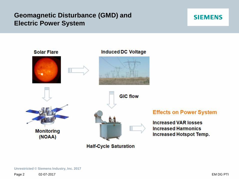
Geomagnetic Disturbance (GMD) and Electric Power System
Page 3
Unrestricted © Siemens Industry, Inc. 201702-07-2017 EM DG PTI
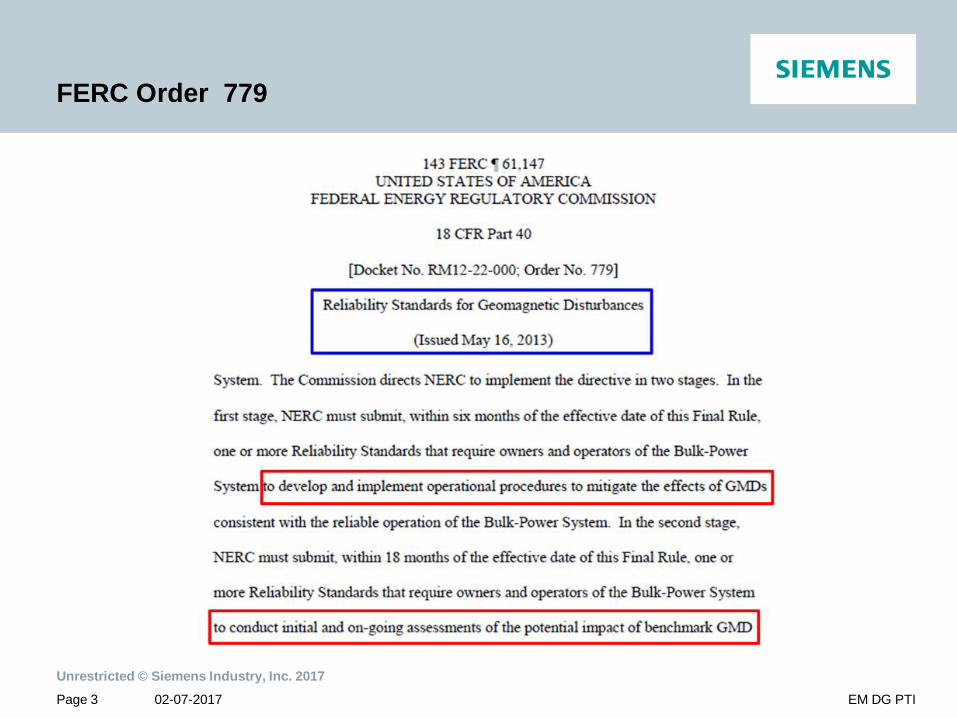
FERC Order 779
Page 4
Unrestricted © Siemens Industry, Inc. 201702-07-2017 EM DG PTI
FERC Order 779 (continued)
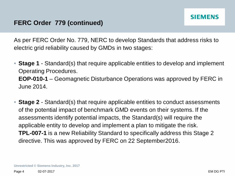
As per FERC Order No. 779, NERC to develop Standards that address risks to electric grid reliability caused by GMDs in two stages:
• Stage 1 - Standard(s) that require applicable entities to develop and implement Operating Procedures. EOP-010-1 – Geomagnetic Disturbance Operations was approved by FERC in June 2014.
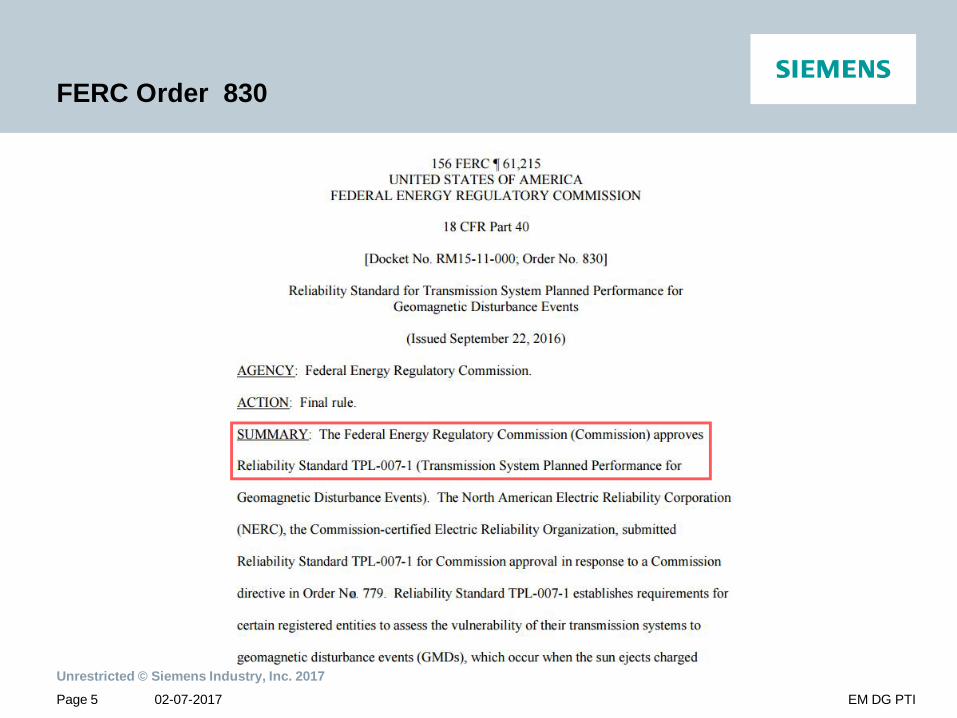
• Stage 2 - Standard(s) that require applicable entities to conduct assessments of the potential impact of benchmark GMD events on their systems. If the assessments identify potential impacts, the Standard(s) will require the applicable entity to develop and implement a plan to mitigate the risk.TPL-007-1 is a new Reliability Standard to specifically address this Stage 2 directive. This was approved by FERC on 22 September2016.
Page 5
Unrestricted © Siemens Industry, Inc. 201702-07-2017 EM DG PTI
FERC Order 830
Page 6
Unrestricted © Siemens Industry, Inc. 201702-07-2017 EM DG PTI
FERC Order 830 (continued)
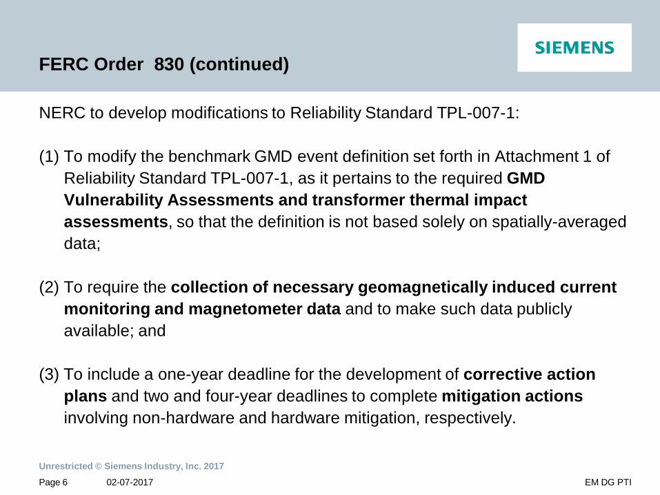
NERC to develop modifications to Reliability Standard TPL-007-1:
(1) To modify the benchmark GMD event definition set forth in Attachment 1 of Reliability Standard TPL-007-1, as it pertains to the required GMD Vulnerability Assessments and transformer thermal impact assessments, so that the definition is not based solely on spatially-averaged data;
(2) To require the collection of necessary geomagnetically induced current monitoring and magnetometer data and to make such data publicly available; and
(3) To include a one-year deadline for the development of corrective action plans and two and four-year deadlines to complete mitigation actions involving non-hardware and hardware mitigation, respectively.
Page 7
Unrestricted © Siemens Industry, Inc. 201702-07-2017 EM DG PTI
What is NERC TPL-007-1?
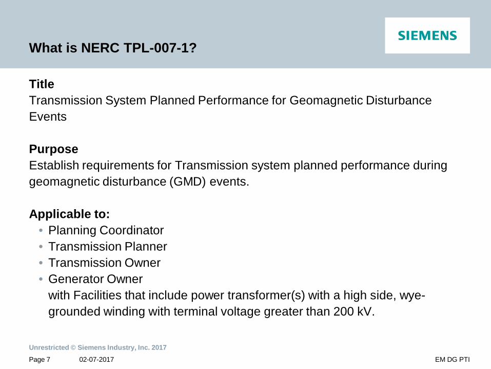
TitleTransmission System Planned Performance for Geomagnetic Disturbance Events
PurposeEstablish requirements for Transmission system planned performance during geomagnetic disturbance (GMD) events.
Applicable to:• Planning Coordinator• Transmission Planner• Transmission Owner• Generator Owner
with Facilities that include power transformer(s) with a high side, wye-grounded winding with terminal voltage greater than 200 kV.

Page 8
Unrestricted © Siemens Industry, Inc. 201702-07-2017 EM DG PTI
TPL-007-1Requirements and Measures – R1 and M1
Geomagnetic Disturbances (GMDs) Vulnerability Assessment: Documented evaluation of potential susceptibility to voltage collapse, Cascading, or localized damage of equipment due to GMD.
R1: Identify Responsible EntitiesIdentify individual or joint responsibilities of the Planning Coordinators and Transmission Planners in the Planning coordinator’s planning area for maintaining models and performing studies needed to complete GMD Vulnerability Assessment required in R4.
M1: Responsible entities provide documented information on roles and responsibilities.

Page 9
Unrestricted © Siemens Industry, Inc. 201702-07-2017 EM DG PTI
TPL-007-1Requirements and Measures – R2 and M2
R2: Grid and GIC system ModelsResponsible entities maintain System models and GIC System (DC) models of the responsible entity’s planning area for performing the studies needed to complete GMD Vulnerability Assessment(s).
M2: Responsible entities have System models and GIC system models in either electronic or hard copy format.

Page 10
Unrestricted © Siemens Industry, Inc. 201702-07-2017 EM DG PTI
TPL-007-1 Requirements and Measures – R3 and M3
R3: Acceptable Grid Steady State Voltage Limits criteriaResponsible entities have criteria for acceptable System steady state voltage performance for its System during the benchmark GMD event.
M3: Responsible entities have acceptable System steady state voltage performance criteria documented in either electronic or hard copy format.
Page 11
Unrestricted © Siemens Industry, Inc. 201702-07-2017 EM DG PTI
TPL-007-1Requirements – R4
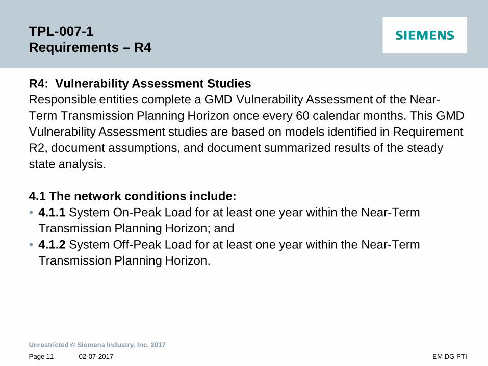
R4: Vulnerability Assessment StudiesResponsible entities complete a GMD Vulnerability Assessment of the Near-Term Transmission Planning Horizon once every 60 calendar months. This GMD Vulnerability Assessment studies are based on models identified in Requirement R2, document assumptions, and document summarized results of the steady state analysis.
4.1 The network conditions include:• 4.1.1 System On-Peak Load for at least one year within the Near-Term
Transmission Planning Horizon; and• 4.1.2 System Off-Peak Load for at least one year within the Near-Term
Transmission Planning Horizon.
Page 12
Unrestricted © Siemens Industry, Inc. 201702-07-2017 EM DG PTI
TPL-007-1Requirements and Measures – R4 (cont’d) and M4
4.2 The studies are conducted based on the benchmark GMD event to determine whether system meets performance requirements ( in Table 1).
4.3 Within 90 calendar days of completion of the studies, the GMD Vulnerability Assessment is provided to responsible entity’s Reliability Coordinator, adjacent Planning Coordinators, adjacent Transmission Planners and any functional entity that request it and has a reliability related need. • 4.3.1 Any documented comments by a recipient of these studies, the
responsible entity provide documented response within 90 calendar days.
M4: Responsible entities have dated evidence in either electronic or hard copy format of actions performed to fulfill requirements R4.

Page 13
Unrestricted © Siemens Industry, Inc. 201702-07-2017 EM DG PTI
TPL-007-1R4 – Performance Criteria
The vulnerability Assessment Studies shall meet following performance criteria.(Table 1 of TPL-007-1)• Voltage collapse, Cascading and uncontrolled islanding shall not occur.• Generation loss is acceptable as a consequence of the planning event.• Planned System adjustments such as Transmission configuration changes and
re-dispatch of generation are allowed if such adjustments are executable within the time duration applicable to the Facility Ratings.
• The GMD event could cause tripping of Reactive Power Compensation Devices and other Transmission Facilities as a result of Protection System operation or mis-operation due to harmonics during the GMD event, then load loss and/or interruption of firm transmission service allowed.
Page 14
Unrestricted © Siemens Industry, Inc. 201702-07-2017 EM DG PTI
TPL-007-1Requirements and Measures – R5 and M5
R5: GIC(t) Flow for Thermal Impact AssessmentResponsible entities provide GIC flow information to be used for the transformer thermal impact assessment specified in Requirement R6. The GIC flow information include:• 5.1 The maximum effective GIC value for the worst case geoelectric field
orientation for the benchmark GMD event. This value is provided to the Transmission Owner or Generator Owner that owns BES power transformer in the planning area.
• 5.2 Responsible entities provide the effective GIC time series, GIC(t), calculated using the benchmark GMD event upon request from Transmission Owner or Generator Owner within 90 calendar days.
M5: Responsible entities have dated evidence in either electronic or hard copy format of actions performed to fulfill requirements R5.
Page 15
Unrestricted © Siemens Industry, Inc. 201702-07-2017 EM DG PTI
TPL-007-1Requirements and Measures – R6 and M6
R6: Thermal Impact Assessment StudiesTransmission Owner and Generator Owner conduct a thermal impact assessment for applicable power transformers where the maximum effective GIC value provided in Requirement R5.1 is 75 A per phase or greater. The thermal impact assessment shall:• 6.1 Be based on the effective GIC flow information provided in R5• 6.2 Document assumptions used in the analysis;• 6.3 Describe suggested actions and supporting analysis to mitigate the impact
of GICs, if any• 6.4 Be performed and provided to responsibilities entities within 24 calendar
months of receiving GIC flow information.
M6: Transmission Owner and Generator Owner have dated evidence in either electronic or hard copy format of actions performed to fulfill requirements R6.

Page 16
Unrestricted © Siemens Industry, Inc. 201702-07-2017 EM DG PTI
TPL-007-1Requirements and Measures – R7 and M7
R7: Corrective Action PlanResponsible entities develop a Corrective Action Plan addressing how the performance requirements will be met in case of the GMD Vulnerability Assessment conducted as in R4 shows that the System does not meet the performance requirements of Table 1 (R4).• 7.1 List system deficiencies and the associated actions needed to achieve
required system performance. Examples of such actions include:• Installation, modification, retirement or removal of transmission and
generation facilities and any associated equipment.• Installation, modification, or removal of protection systems or special
protection systems.• Use of operating procedures, specifying how long they will be needed as part
of corrective action plan.• Use of demand-side management, new technologies etc.
Page 17
Unrestricted © Siemens Industry, Inc. 201702-07-2017 EM DG PTI
TPL-007-1Requirements and Measures – R7 (cont’d) and M7
• 7.2 Review corrective action plans in subsequent GMD vulnerability assessments until it is determined that system meets performance requirements
• 7.3 Provide corrective action plans to responsible entity’s Reliability Coordinator, adjacent Planning Coordinators, adjacent Transmission Planners and any functional entity that request it and has a reliability related need within 90 calendar days after completing GMD vulnerability assessments. (Note: FERC order 830: to include one-year deadline for the development of corrective action plans and two and four-year deadlines to complete mitigation actions involving non-hardware and hardware mitigation, respectively.)
• 7.3.1 Any documented comments by a recipient of these Corrective Action Plans, the responsible entity provide documented response within 90 calendar days.
M7: Responsible entity’s have dated evidence in either electronic or hard copy format of actions performed to fulfill requirements R7.
Earth Conductivity Models
usa.siemens.com/digitalgridUnrestricted © Siemens Industry, Inc. 2017
Page 19
Unrestricted © Siemens Industry, Inc. 201702-07-2017 EM DG PTI
The Earth Model
• The geomagnetic field variations experienced by power systems at the earth’s surface originate from electric currents flowing in the ionosphere or magnetosphere at heights of 100 km or greater.
• Compared to the heights of these source currents, the height of the transmission lines is insignificant and the electric field at the height of the transmission line can be assumed to be the same as the electric field at the earth’s surface.
• Given the range of frequencies relevant to GIC (1 mHz to 1 Hz) and the conductivity values within the earth, magnetic field variations can penetrate hundreds of kilometers below the surface.
• Thus, the conductivity down through the earth's crust and into the mantle must be taken into account when determining the electric field at the surface.
• Layered earth models with depths of up to 1000 km are considered.
Page 20
Unrestricted © Siemens Industry, Inc. 201702-07-2017 EM DG PTI
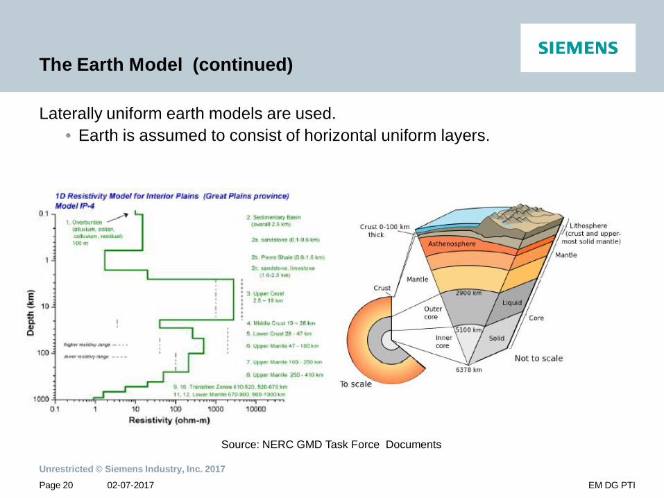
The Earth Model (continued)
Laterally uniform earth models are used.• Earth is assumed to consist of horizontal uniform layers.
Source: NERC GMD Task Force Documents

Page 21
Unrestricted © Siemens Industry, Inc. 201702-07-2017 EM DG PTI
1-D Earth Conductivity Models of US
• Developed by United States Geological Survey (USGS)http://geomag.usgs.gov/conductivity
• 20 Earth Models cover geographical area of U.S.
Source: NERC GMD Task Force Documents
Page 22
Unrestricted © Siemens Industry, Inc. 201702-07-2017 EM DG PTI
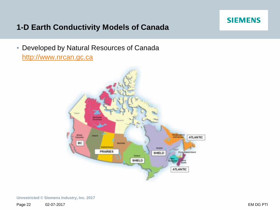
1-D Earth Conductivity Models of Canada
• Developed by Natural Resources of Canadahttp://www.nrcan.gc.ca
Benchmark GMD Eventusa.siemens.com/digitalgridUnrestricted © Siemens Industry, Inc. 2017
Page 24
Unrestricted © Siemens Industry, Inc. 201702-07-2017 EM DG PTI
Definition
The benchmark GMD event defines the geoelectric field values used to compute GIC flows that are needed to conduct a GMD Vulnerability Assessment as per TPL-007-1. It is composed of the following elements:
1. a reference peak geoelectric field amplitude of 8 V/km derived from statistical analysis of historical magnetometer data;
2. scaling factors to account for local geomagnetic latitude; 3. scaling factors to account for local earth conductivity; and 4. a reference geomagnetic field time series or waveshape to facilitate time-
domain analysis of GMD impact on equipment.
The data file of the benchmark geomagnetic field wave shape and its description is available on the NERC GMD Task Force project page:
http://www.nerc.com/comm/PC/Pages/Geomagnetic-Disturbance-Task-Force-(GMDTF)-2013.aspx
Note: This will be further revised as per FERC Order 830.
Page 25
Unrestricted © Siemens Industry, Inc. 201702-07-2017 EM DG PTI
Benchmark Geomagnetic Field Wave Shape
• The geomagnetic field measurement record of the March 13-14 1989 GMD event, measured at NR Canada’s Ottawa geomagnetic observatory is the basis for the reference geomagnetic field wave shape.
• The geomagnetic latitude of the Ottawa geomagnetic observatory is 55°therefore, the amplitude of the geomagnetic field measurement data were scaled up to the 60° reference geomagnetic latitude such that the resulting peak geoelectric field amplitude computed using the reference earth model was 8 V/km.
• Sampling rate for the geomagnetic field wave shape is 10 seconds.
Page 26
Unrestricted © Siemens Industry, Inc. 201702-07-2017 EM DG PTI
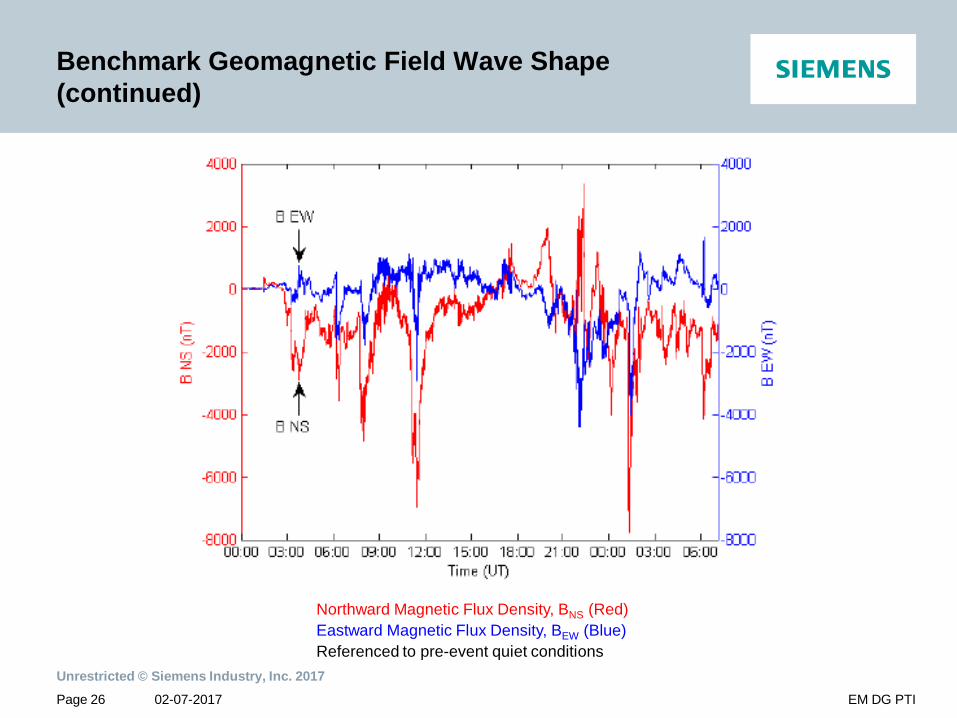
Benchmark Geomagnetic Field Wave Shape (continued)
Northward Magnetic Flux Density, BNS (Red)Eastward Magnetic Flux Density, BEW (Blue)Referenced to pre-event quiet conditions
Page 27
Unrestricted © Siemens Industry, Inc. 201702-07-2017 EM DG PTI
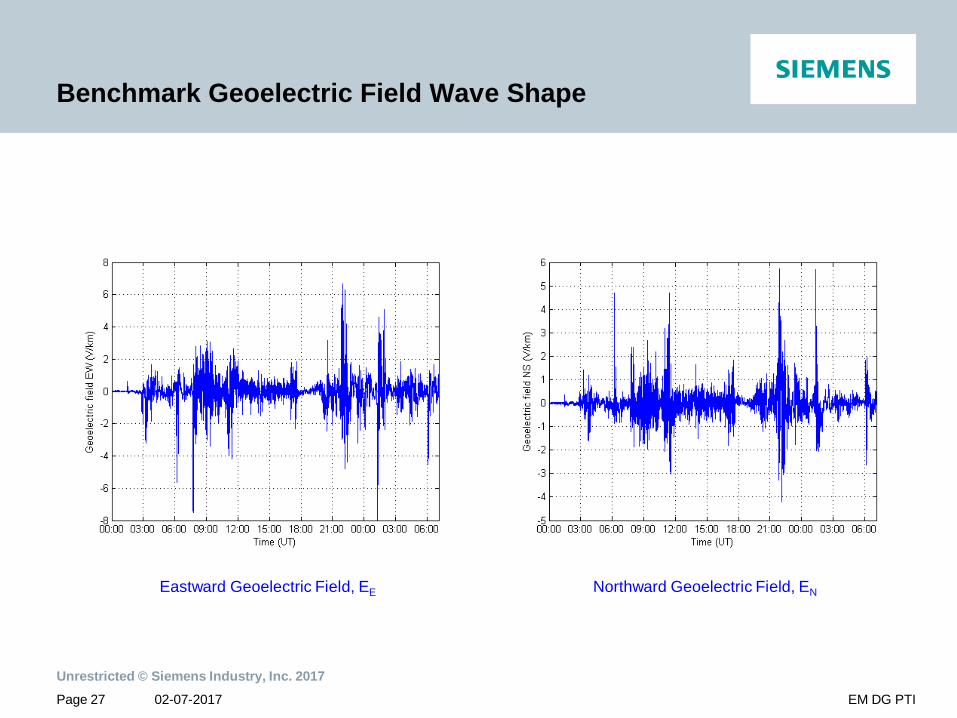
Benchmark Geoelectric Field Wave Shape
Eastward Geoelectric Field, EE Northward Geoelectric Field, EN
Page 28
Unrestricted © Siemens Industry, Inc. 201702-07-2017 EM DG PTI
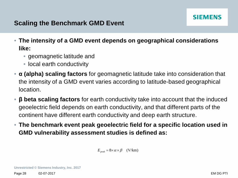
Scaling the Benchmark GMD Event
• The intensity of a GMD event depends on geographical considerations like:
• geomagnetic latitude and • local earth conductivity
• (alpha) scaling factors for geomagnetic latitude take into consideration that the intensity of a GMD event varies according to latitude-based geographical location.
• beta scaling factors for earth conductivity take into account that the induced geoelectric field depends on earth conductivity, and that different parts of the continent have different earth conductivity and deep earth structure.
• The benchmark event peak geoelectric field for a specific location used in GMD vulnerability assessment studies is defined as:
(V/km)8peakE
Page 29
Unrestricted © Siemens Industry, Inc. 201702-07-2017 EM DG PTI
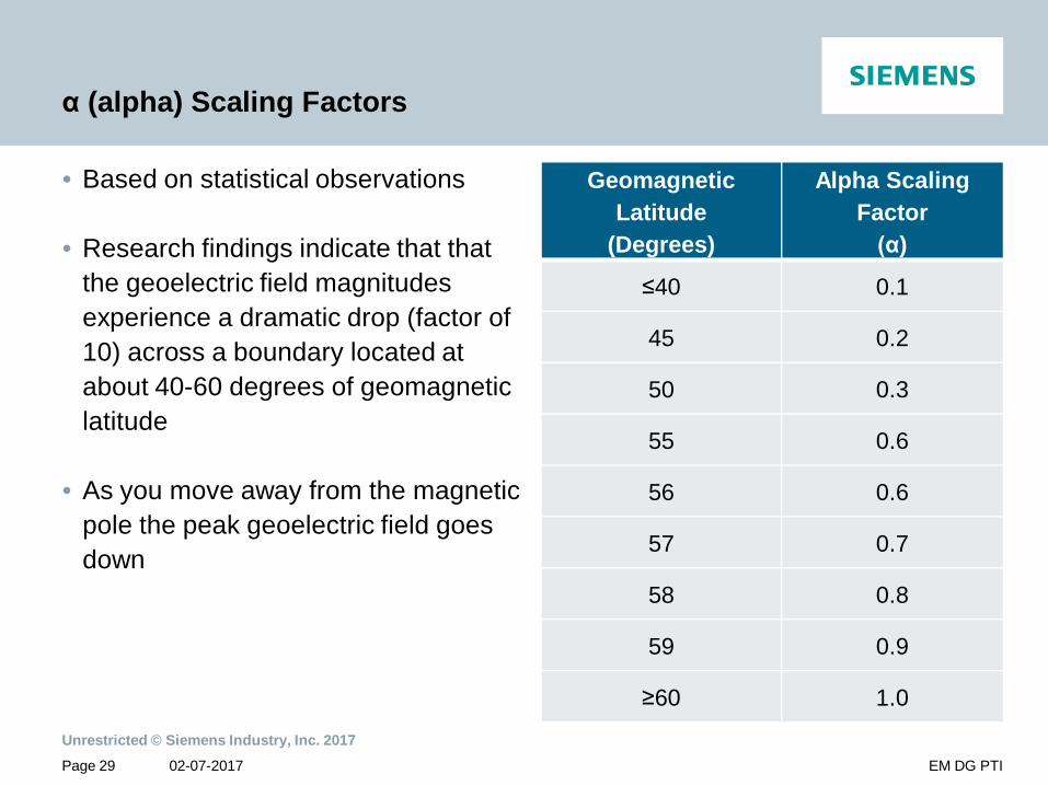
(alpha) Scaling Factors
• Based on statistical observations
• Research findings indicate that that the geoelectric field magnitudes experience a dramatic drop (factor of 10) across a boundary located at about 40-60 degrees of geomagnetic latitude
• As you move away from the magnetic pole the peak geoelectric field goes down
Geomagnetic Latitude
(Degrees)
Alpha Scaling Factor
)
40 0.1
45 0.2
50 0.3
55 0.6
56 0.6
57 0.7
58 0.8
59 0.9
60 1.0
Page 30
Unrestricted © Siemens Industry, Inc. 201702-07-2017 EM DG PTI
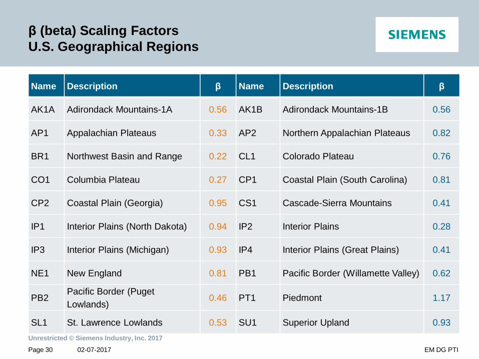
(beta) Scaling FactorsU.S. Geographical Regions
Name Description Name Description
AK1A Adirondack Mountains-1A 0.56 AK1B Adirondack Mountains-1B 0.56
AP1 Appalachian Plateaus 0.33 AP2 Northern Appalachian Plateaus 0.82
BR1 Northwest Basin and Range 0.22 CL1 Colorado Plateau 0.76
CO1 Columbia Plateau 0.27 CP1 Coastal Plain (South Carolina) 0.81
CP2 Coastal Plain (Georgia) 0.95 CS1 Cascade-Sierra Mountains 0.41
IP1 Interior Plains (North Dakota) 0.94 IP2 Interior Plains 0.28
IP3 Interior Plains (Michigan) 0.93 IP4 Interior Plains (Great Plains) 0.41
NE1 New England 0.81 PB1 Pacific Border (Willamette Valley) 0.62
PB2Pacific Border (Puget Lowlands)
0.46 PT1 Piedmont 1.17
SL1 St. Lawrence Lowlands 0.53 SU1 Superior Upland 0.93
Page 31
Unrestricted © Siemens Industry, Inc. 201702-07-2017 EM DG PTI
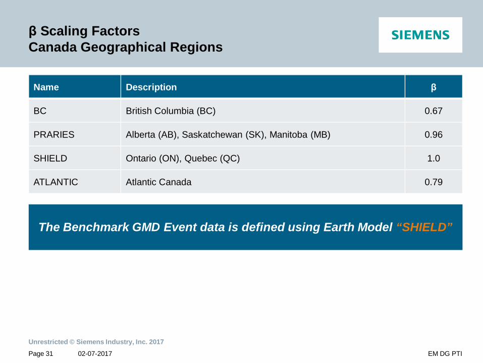
Scaling FactorsCanada Geographical Regions
Name Description
BC British Columbia (BC) 0.67
PRARIES Alberta (AB), Saskatchewan (SK), Manitoba (MB) 0.96
SHIELD Ontario (ON), Quebec (QC) 1.0
ATLANTIC Atlantic Canada 0.79
The Benchmark GMD Event data is defined using Earth Model “SHIELD”
Page 32
Unrestricted © Siemens Industry, Inc. 201702-07-2017 EM DG PTI
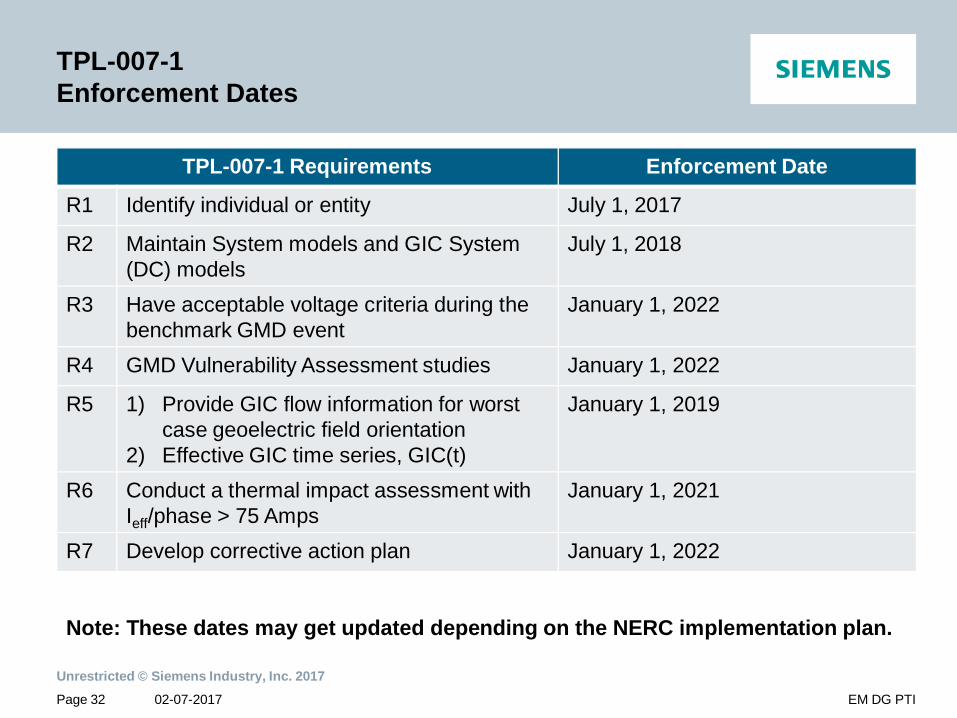
TPL-007-1 Enforcement Dates
TPL-007-1 Requirements Enforcement Date
R1 Identify individual or entity July 1, 2017
R2 Maintain System models and GIC System (DC) models
July 1, 2018
R3 Have acceptable voltage criteria during the benchmark GMD event
January 1, 2022
R4 GMD Vulnerability Assessment studies January 1, 2022
R5 1) Provide GIC flow information for worst case geoelectric field orientation
2) Effective GIC time series, GIC(t)
January 1, 2019
R6 Conduct a thermal impact assessment with Ieff/phase > 75 Amps
January 1, 2021
R7 Develop corrective action plan January 1, 2022
Note: These dates may get updated depending on the NERC implementation plan.
Page 33
Unrestricted © Siemens Industry, Inc. 201702-07-2017 EM DG PTI
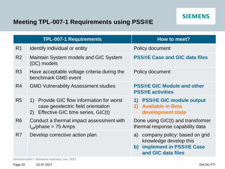
Meeting TPL-007-1 Requirements using PSS®E
TPL-007-1 Requirements How to meet?
R1 Identify individual or entity Policy document
R2 Maintain System models and GIC System (DC) models
PSS®E Case and GIC data files
R3 Have acceptable voltage criteria during the benchmark GMD event
Policy document
R4 GMD Vulnerability Assessment studies PSS®E GIC Module and other PSS®E activities
R5 1) Provide GIC flow information for worst case geoelectric field orientation
2) Effective GIC time series, GIC(t)
1) PSS®E GIC module output2) Available in Beta
development stateR6 Conduct a thermal impact assessment with
Ieff/phase > 75 AmpsDone using GIC(t) and transformer thermal response capability data
R7 Develop corrective action plan a) company policy: based on grid knowledge develop this
b) implement in PSS®E Case and GIC data files

Page 34
Unrestricted © Siemens Industry, Inc. 201702-07-2017 EM DG PTI
Siemens PTI Expertise in Meeting TPL-007-1 Requirements
Why should you partner with Siemens PTI to demonstrate compliance with TPL-007-1?• We are the developers and users of the PSS®E GIC module, with knowledge
of intricate details of the software tool and PSS®E network models• PTI consulting has performed GIC analysis study for a utility in Midwest• Our consultants are experts in power systems planning and are equipped to
make the necessary assumptions for missing data• 45+ years of proven industry experience• Provider of vendor neutral consulting services• PSS®E GIC Module has been actively used by many utilities and consultants
Resourcesusa.siemens.com/digitalgridUnrestricted © Siemens Industry, Inc. 2017

Page 36
Unrestricted © Siemens Industry, Inc. 201702-07-2017 EM DG PTI
Resources
• NERC Standard TPL-007-1: Transmission System Planned Performance for Geomagnetic Disturbance Events, Dec 2014
• NERC Geomagnetic Disturbance Planning Guide, Dec 2013• NERC Application Guide for Computing GIC in the Bulk Power System, Dec
2013• NERC 2012 Special Reliability Assessment Interim Report: Effects of
Geomagnetic Disturbances on the Bulk Power System, Feb 2012• NERC Transformer Thermal Impact Assessment White Paper• NERC GMD Task Force Resources• NERC Geomagnetic Disturbance Mitigation• IEEE Publications
Page 37
Unrestricted © Siemens Industry, Inc. 201702-07-2017 EM DG PTI
NERC – GMD Planning Guide
Provides guidance to planning engineers on how to incorporate and take into account the effects of GMD in system planning studies.Objectives of GMD planning studies are:1. Assess the behavior of the system in terms of voltage limits, potential voltage
collapse, and cascading outages during GMD events by taking into account transformer var absorption caused by half-cycle saturation. The system must perform within applicable limits under various contingencies – such as forced outage of a shunt capacitor bank or static var compensator (SVC).
2. Assess thermal impacts on equipment. Hot spot heating of transformers due to GIC during a GMD event is a primary concern since automatic protection systems are not likely to operate on this basis.
3. Assess the performance of protection and control (P&C) systems in terms of security and dependability.
Page 38
Unrestricted © Siemens Industry, Inc. 201702-07-2017 EM DG PTI
NERC – Application Guide for Computing GIC in the Bulk Power System
• Explains the theoretical background behind calculating geomagnetically-induced currents (GIC).
• Assumptions and techniques used in modern GMD simulation tools are provided.
• The BES network data that need to be considered in GIC analysis is described.
Page 39
Unrestricted © Siemens Industry, Inc. 201702-07-2017 EM DG PTI
NERC – Transformer Thermal Impact White Paper
• Process for performing Transformer Thermal Impact Assessment using GIC flow time series, GIC(t) and Transformer Thermal Capability Curves
• Method to calculate GIC flow time series, GIC(t) for each transformer for duration of GMD event

Page 40
Unrestricted © Siemens Industry, Inc. 201702-07-2017 EM DG PTI
Contact
Krishnat PatilSenior Staff Software EngineerSiemens PTI
Phone: +1 518 395 5081
E-mail:[email protected]
Jyothirmai ChittyreddyStaff ConsultantSiemens PTI
Phone: +1 972 621 5699
E-mail:[email protected]
usa.siemens.com/digitalgrid

Page 41
Unrestricted © Siemens Industry, Inc. 201702-07-2017 EM DG PTI
On to Step 3…
Live Demonstration: PSS®E GIC – Fundamentals DemonstrationNEW DATE
Thursday, February 16, 2017 | 2:00 p.m. EST
Siemens Power Technologies International experts will take you through the basics of analyzing geomagnetic disturbances on the grid including gathering/creating GIC data and running a GIC study in PSS®E.The results of a PSS®E GIC analysis include:
• Transmission line induced DC Voltages• DC voltages at network buses and substation ground buses• GIC flow in transmission lines, former windings and substation grounds• Reactive power losses in transformers• Substation ground and branch GIC flows• Bus voltages
Look for your exclusive invitation!