ncs 2000 product update
TRANSCRIPT
NCS 2000 Product Update Lorenzo Ghioni
March 3rd, 2015
Cisco Federal Packet Optical Networking Conference

126 100G Customers To Date
10,217 100G WDM Line Cards in 12 QRTs
80% of 100G WDM LCs are used for 10G Muxponders
IPoWDM LCs are about 6% of total
100G is not in a bubble and transition from 10G to 100G Clients expected soon
Is 100G For Real?!?

• Started shipping 100G SD-FEC Line cards in November 2014, with Release 10.1 • Leverages on Cisco’s 2nd generation nLight Silicon ASIC, which
integrates a Coherent DSP, Transmit Signal Shaping and Soft Decision FEC (20% OH)
• 2dB better B2B OSNR vs. HD-FEC Line Cards • Grid-less Tunability (0.1GHz steps) • <50ms Protection Switching
• Release 10.3 SW enables 200G operating mode on Multi-Rate line card
Available 100G/200G Line Card
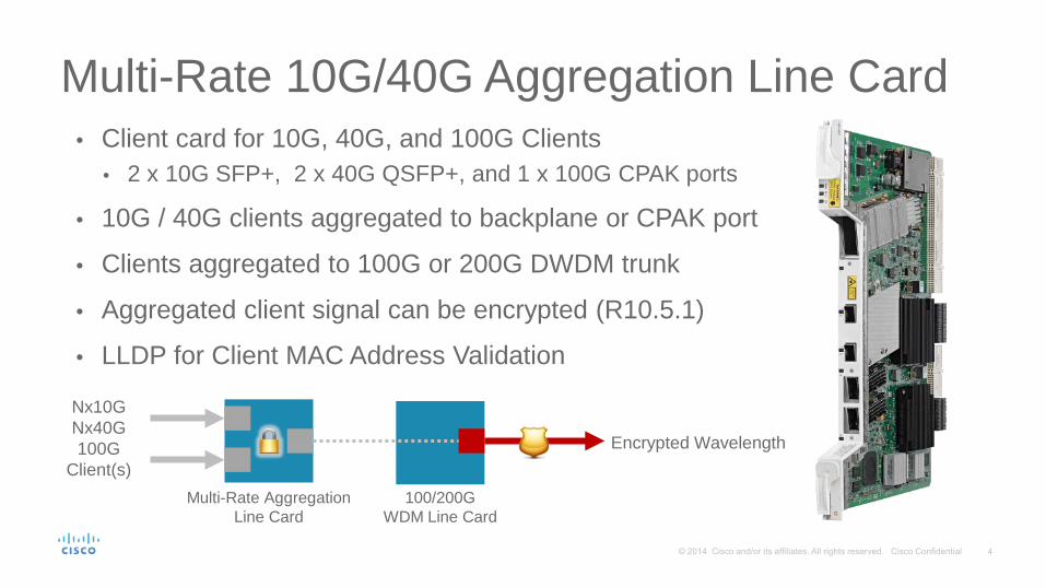
Multi-Rate 10G/40G Aggregation Line Card • Client card for 10G, 40G, and 100G Clients
• 2 x 10G SFP+, 2 x 40G QSFP+, and 1 x 100G CPAK ports
• 10G / 40G clients aggregated to backplane or CPAK port
• Clients aggregated to 100G or 200G DWDM trunk
• Aggregated client signal can be encrypted (R10.5.1)
• LLDP for Client MAC Address Validation
Multi-Rate Aggregation Line Card
Nx10G Nx40G 100G
Client(s) 100/200G
WDM Line Card
Encrypted Wavelength

10G/40G/100G Encryption Options
• 10G & 40G Clients can be Aggregated and then Encrypted over an OTU-4/200G Wavelength
• 100G Client(s) can be Encrypted over an OTU-4/200G Wavelength
• 10G & 40G Clients can be Aggregated and then Encrypted over an LR4 OTU-4 Signal
• 100G Client can be Encrypted over an LR4 OTU-4 Signal

200G Muxponding Configurations
10G/40G Multi-Rate
Muxponder
10x10G Line Card
200G LC Integrated
CPAK Client
1 1 0
2 0 0
1 0 1
200G Muxponder Configurations
10G SFP+
Chassis
Backplane
10x10G Client
Chassis
Backplane
CPAK
40G QSFP
10G SFP+
Multi-Rate Client
Chassis
Backplane
200G DWDM
CPAK
200G Trunk
Note: 2x CFP Line Card is not supported with SD-FEC WDM Line Card

Flexible Modulation – Reach vs. Capacity
BPSK 28 GBaud 56 Gbps 50 Gbps 10,000 km
QPSK 32 GBaud 112 Gbps 100 Gbps 6,800 km
16-QAM 35 GBaud 224 Gbps 200 Gbps 1,200 km
Modulation Baud Rate Line Rate Payload Rate Distance
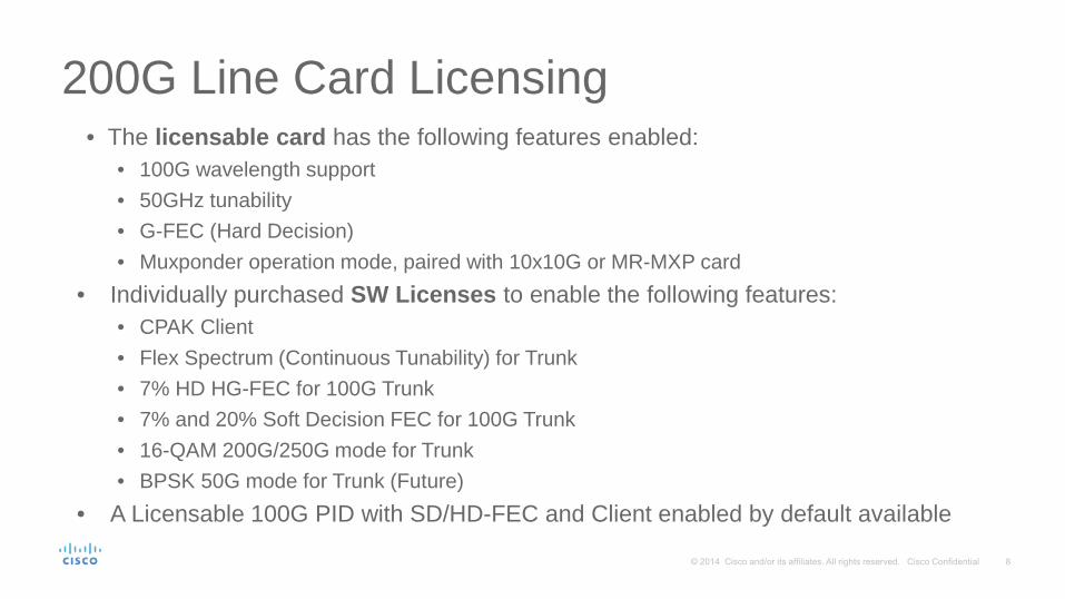
200G Line Card Licensing • The licensable card has the following features enabled:
• 100G wavelength support • 50GHz tunability • G-FEC (Hard Decision) • Muxponder operation mode, paired with 10x10G or MR-MXP card
• Individually purchased SW Licenses to enable the following features: • CPAK Client • Flex Spectrum (Continuous Tunability) for Trunk • 7% HD HG-FEC for 100G Trunk • 7% and 20% Soft Decision FEC for 100G Trunk • 16-QAM 200G/250G mode for Trunk • BPSK 50G mode for Trunk (Future)
• A Licensable 100G PID with SD/HD-FEC and Client enabled by default available

What Are We Working On?

• Pluggables-based 250G WDM Line Card • NCS 2015 (M15) Shelf • 9-Port and 20-Port Flex-Spectrum SMR Line Cards • 12-Port and 16-Port Contentionless Add/Drop Line Cards • OTDR & OSC Integration
Key Work-In-Progress Items

250G Muxponder Line Card Single wavelength supporting:
• 50G BPSK • 100G QPSK • 200G 16-QAM • 250G 16-QAM
Pluggable WDM CFP2 Interface CPAK client interfaces supporting:
• 100G LR4 • 100G SR10 • 10x10G LR / SR
100G, 10x10G
100G, 10x10G
50/100/200/250G

250G Wavelengths in NCS 2015 / 2006 CFP-2
250G WDM Trunk
CFP-2 250G WDM Trunk
CPAK 100G / 40G / 10G
Clients
• 2Tbps (Client + Trunk) as 4x 250G Wavelengths in M6 (6RU)
• 5Tbps (Client + Trunk) as 10x 250G Wavelengths in M15 (14RU)

NCS 2015 - New 15-Slot Shelf 17 Slots / 15 Line Card slots w/Redundant Controllers
14RU Height - 3 Shelves per 7’ Rack
Single Shelf to support ANSI & ETSI Standards - 300mm Depth
Front-To-Back Air Flow
Can be installed in 19” or 23” and 600mm Racks
Supports M6 / NCS 2000 Line Cards
Up to 900x 10GE or 90x 100GE per Rack
Designed to support up to 300W/slot
Redundant DC or AC Power (up to 3+1 configuration)
Can be subtended to existing M6 / NCS 2000 Multi-Shelf Nodes

AIR FLOW
NCS 2015 Shelf – DC Power Version
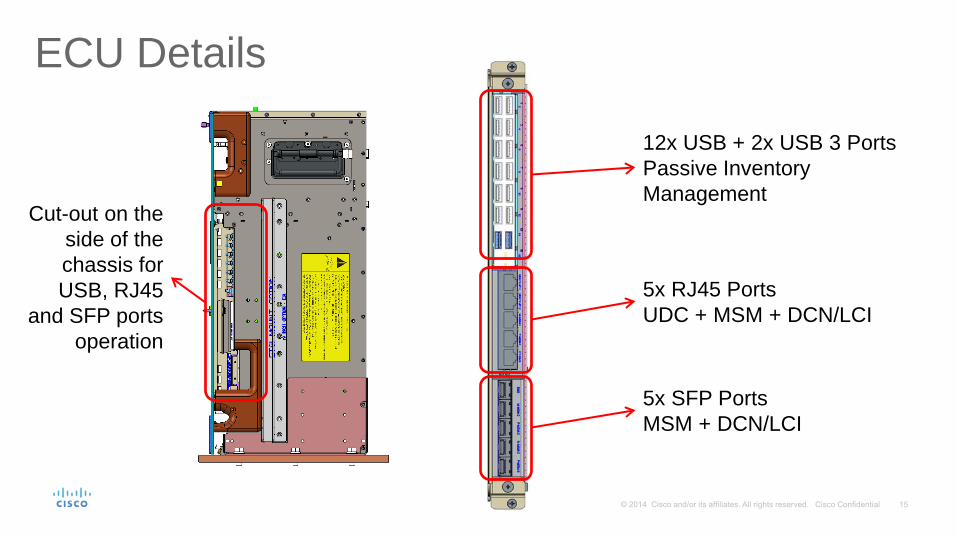
ECU Details
12x USB + 2x USB 3 Ports Passive Inventory Management
5x RJ45 Ports UDC + MSM + DCN/LCI
5x SFP Ports MSM + DCN/LCI
Cut-out on the side of the chassis for USB, RJ45
and SFP ports operation

Flex-Spectrum ROADM Node Block Diagram FS SMR
(Degree A)
FS SMR (Degree B)
FS SMR (Degree C)
FS SMR (Degree D)
CCOFS Add/Drop
COFS Add/Drop
CD Add/Drop
Mesh Patch Panel
WD
M
Interface
WD
M
Interface
WD
M
Interface
WD
M
Interface
WD
M
Interface
WD
M
Interface
WD
M
Interface
WD
M
Interface
WD
M
Interface

Flex Spectrum Single Module ROADMs
Improved Scalability: 25% More Ports vs. 16-WXC-FS
Greater Integration: ROADM + Pre-Amplifier + Booster Amplifier Combined in a Single Line Card
Better Density: From 4-slot to 1-slot per Degree
Next Generation Amplification: Switchable Gain Pre-Amplifier from 0dB to 35dB of Span Loss with a single Line Card

20-port Flex Spectrum SMR
3x MPOs For Degree Interconnection or Add/Drop TX & RX Monitor
Ports
Connection with Span Fibers Optical Service
Channel Add/Drop

9-port Flex Spectrum SMR
2x MPOs + 1x LCs for Degree Interconnection or Add/Drop
TX & RX Monitor Ports
Connection with Span Fibers
Optical Service Channel Add/Drop

Contentionless (CCOFS) Add/Drop CCOFS allows to completely de-couple Add/Drop ports from ROADM
Degrees – This was the last missing piece for WDM to replace SDH/SONET with Full Features Parity
Omni-Directional and Colorless Add/Drop solutions represented intermediate steps, still having limitations with the number of Degrees vs. number of Add/Drop wavelengths
Optimized solution for Coherent Transmission Systems

12-port / 4-degree CCOFS Line Card
4-channels Add/Drop Ports
4-degree Interconnection Ports
4-channels Add/Drop Ports
4-degree Interconnection Ports
4-channels Add/Drop Ports
4-degree Interconnection Ports

16-port / 4-degree CCOFS Line Card
16-channels Add/Drop Ports
4-degree Interconnection Ports
4-degree Expansion Ports

From 4-degree to 12-degree Scalability Directions #1 through #4
16-channels Add/Drop
Directions #5 through #8 Directions #9 through #12

Patch Panel Modules Details
DEG-1
UPG-4
4-fiber pair MPO connectors provide connectivity to: • DEG-5: 5 different degrees with an Any-to-Any pattern
• UPG-4: 4 different degrees with a Mesh pattern
DEG-5
DEG-2 DEG-3 DEG-4 DEG-5 DEG-1 DEG-2 DEG-3 DEG-4
DEG-5 DEG-6 DEG-7 DEG-8

Mesh Patch Panel Details • The 6RU Patch Panel is a passive device integrating an
USB 3.0 Hub
• Up to 14x DEG-5 and UPG-4 Optical Modules can be installed to fully build out the Fiber Shuffle to complete Node Scalability
• Single USB 3.0 cable allows to connect the Fiber Shuffle to the NCS 2000 shelf and to detect the presence and the position of each of the Optical Modules installed
• The Node can understand which Node configuration is being built and to perform checks and report errors or issues
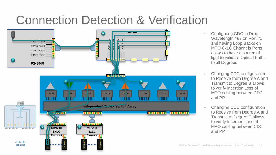
Connection Detection & Verification
TX/RX D
ir A
TX/RX D
ir B
UPG-4
TX/RX D
ir C
TX/RX D
ir D
1x16 1x16 1x16 1x16 1x16 1x16 1x16 1x16
Independent TX/RX Switch Array
MPO to 8xLC
Fan-out
MPO to 8xLC
Fan-out
Loop Back
16x LC Loopback
Loop Back
Loop Back
Loop Back
Direction A
TX/RX Port B
TX/RX Port C
TX/RX Port D
TX/RX Port E
FS-SMR PD
PD
PD
PD PD
PD PD PD
Direction B
Direction C
Direction D
• Configuring CDC to Drop Wavelength #97 on Port #1 and having Loop Backs on MPO-8xLC Channels Ports allows to have a source of light to validate Optical Paths to all Degrees
MPO – 8xLC
• Changing CDC configuration to Receive from Degree A and Transmit to Degree B allows to verify Insertion Loss of MPO cabling between CDC and PP
• Changing CDC configuration to Receive from Degree A and Transmit to Degree C allows to verify Insertion Loss of MPO cabling between CDC and PP

OTDR Integration • Integrated into NCS 20xx Controller Card
• 1 OTDR per Degree – No Sharing OTDR amongst 4-Degrees • Digital – Bit Stream instead of High Power Optical Pulse • In Band – Take measurements directly @ 1518nm, no extrapolations
• Able to support: • Hybrid OSC & OTDR Operation – Continuous monitoring of fiber with OSC connectivity • OTDR-only Operation – During system turn up for faster fiber scanning • OSC-only Operation – For maximum throughput (e.g. SW Download)
• OTDR Sensitivity SW Configurable: • Central Office (0 to 1Km) – Fiber Connectivity check through CO Patch Panels • Raman Active Region (1Km to 25Km) – Check Insertion Losses and Back Reflection • Regional (25Km to 80Km) – Measurement Accuracy to detect issues w/10m resolution • Long Haul (Above 80Km) – Maximum Length spanning w/20m resolution

OTDR Test Bench
Fiber Spools
Optical Switch
OTDR Sample
This is what will be integrated in an XFP package

OTDR Test: Central Office Setup & Results
• 1.2Km of SMF Fiber (Current SW Limitation for Launch Dead zone – to go down to 2meters) • 5-meter patch-cord • 25Km of SMF Fiber

OTDR Test: Raman Region Setup & Results
• 1.2Km of SMF Fiber (Current SW Limitation for Launch Dead zone – to go down to 2meters) • 5-meter patch-cord • 10Km of SMF Fiber • Optical Switch • 20Km of SMF Fiber

OTDR Test: Raman Region (Switch Open) Setup & Results
• 1.2Km of SMF Fiber (Current SW Limitation for Launch Dead zone – to go down to 2meters) • 5-meter patch-cord • 10Km of SMF Fiber • Optical Switch • 20Km of SMF Fiber
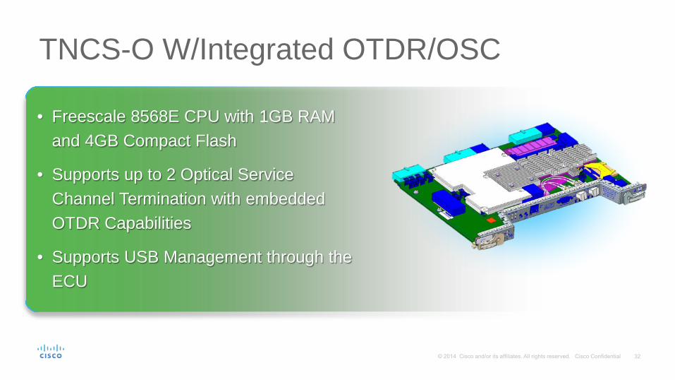
TNCS-O W/Integrated OTDR/OSC
• Freescale 8568E CPU with 1GB RAM and 4GB Compact Flash
• Supports up to 2 Optical Service Channel Termination with embedded OTDR Capabilities
• Supports USB Management through the ECU

OTDR XFP Details • Standard GE Ethernet pluggable Plus
extra component for OTDR functionalities
• Optical Circulator on TX Path to access backward propagating light, detected by a PIN PD and processed by dedicated FPGA
• I2C interface to configure OTDR operation modes and retrieve measured data
• Optical X/bar Switch for shooting both fibers of the link
Standard XFP
Electrical Connector
Signal/Data
Processing FPGA
TX1
TX2
RX1
RX2

OTDR & OSC Operations
• Using TX1 of Near-End XFP and TX2 on Far-End XFP allows to scope the Top Fiber Left-to-Right and the Bottom Fiber Right-to-Left
• OSC flows Left-to-Right in the Top Fiber and Right-to-Left in the Bottom fiber
• OSC can run in parallel with OTDR scans on the span fibers
• Using TX2 of Near-End XFP and TX1 on Far-End XFP allows to scope the Bottom Fiber Left-to-Right and the Top Fiber Right-to-Left
• OSC flows Left-to-Right in the Bottom Fiber and Right-to-Left in the Top fiber
• OSC can run in parallel with OTDR scans on the span fibers
OTDR OSC
OSC
OTDR Near-End Far-End OTDR OSC
OSC OTDR
Near-End Far-End
NCS 2K Roadmap
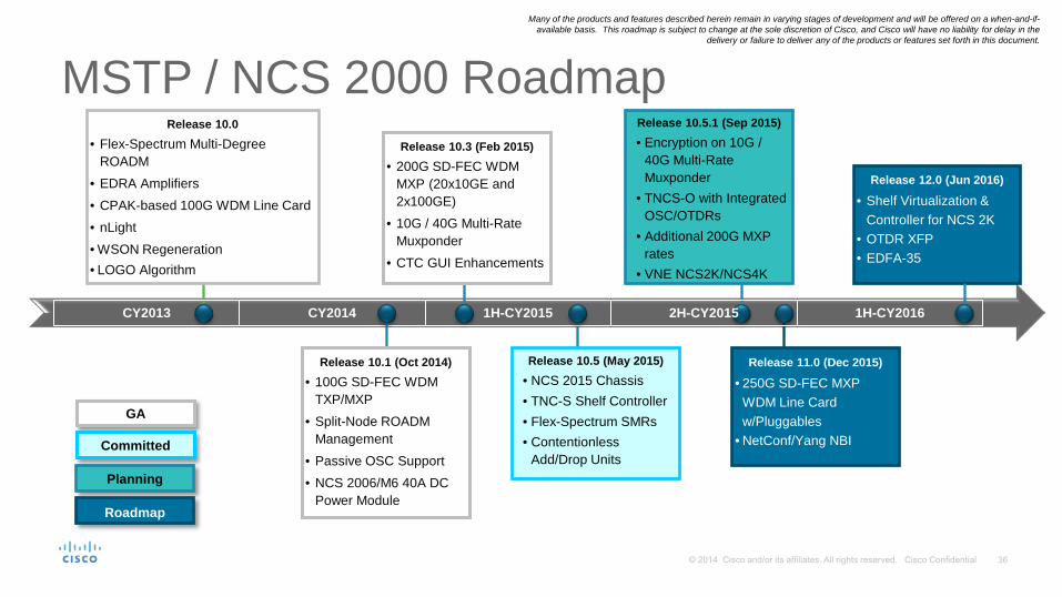
Many of the products and features described herein remain in varying stages of development and will be offered on a when-and-if-available basis. This roadmap is subject to change at the sole discretion of Cisco, and Cisco will have no liability for delay in the
delivery or failure to deliver any of the products or features set forth in this document.
MSTP / NCS 2000 Roadmap
Release 11.0 (Dec 2015)
• 250G SD-FEC MXP WDM Line Card w/Pluggables
• NetConf/Yang NBI
CY2014 1H-CY2016
Release 10.1 (Oct 2014) • 100G SD-FEC WDM
TXP/MXP • Split-Node ROADM
Management • Passive OSC Support • NCS 2006/M6 40A DC
Power Module
Release 10.5 (May 2015) • NCS 2015 Chassis • TNC-S Shelf Controller • Flex-Spectrum SMRs • Contentionless
Add/Drop Units
CY2013
Release 10.0 • Flex-Spectrum Multi-Degree
ROADM • EDRA Amplifiers • CPAK-based 100G WDM Line Card • nLight • WSON Regeneration • LOGO Algorithm
1H-CY2015
GA
Planning
Committed
Roadmap
Release 10.5.1 (Sep 2015) • Encryption on 10G /
40G Multi-Rate Muxponder
• TNCS-O with Integrated OSC/OTDRs
• Additional 200G MXP rates
• VNE NCS2K/NCS4K
Release 12.0 (Jun 2016)
• Shelf Virtualization & Controller for NCS 2K
• OTDR XFP • EDFA-35
2H-CY2015
Release 10.3 (Feb 2015) • 200G SD-FEC WDM
MXP (20x10GE and 2x100GE)
• 10G / 40G Multi-Rate Muxponder
• CTC GUI Enhancements