natural resources conservation service ia-1-1 07/13 natural resources conservation service...
TRANSCRIPT

Iowa IA-1-1 07/13
NATURAL RESOURCES CONSERVATION SERVICE CONSTRUCTION SPECIFICATION
IA-1 SITE PREPARATION
1. SCOPE Site preparation work shall consist of clearing, grubbing, stripping, refuse removal, bank sloping and structure removal on the site as necessary to rid the site of all undesirable materials on or near the surface and prepare the site for the structure. All woody growth within the construction area shall be cleared and all stumps and roots one inch in diameter or larger shall be grubbed from the site. In addition, all areas within 25 feet of the footprint of the structure shall be cleared and grubbed except as directed by NRCS. The work shall also consist of the removal and disposal of structures (including fences) that must be removed to perform other items of work.
For wetland restoration, enhancement, or creation projects, the wetland area shall be disturbed as little as possible and existing naturally vegetated spillway areas shall not be disturbed.
2. FOUNDATION PREPARATION The construction areas shall be stripped a minimum of 6 inches to remove all unsuitable materials such as organic matter, grasses, weeds, sod, debris, and stones larger than 6 inches in diameter.
In an earth embankment foundation area, all channel banks and sharp breaks shall be sloped to no steeper than 1.5 horizontal to 1 vertical.
The foundation area shall be thoroughly scarified before placement of fill material. The surface shall have moisture added or shall be compacted if necessary so that the first layer of fill material can be compacted and bonded to the foundation.
3. STRIPPED MATERIAL DISPOSAL Suitable soil material shall be stockpiled for use as topsoil. The other stripped materials shall be buried, removed from the site, or disposed of as directed by the owner or NRCS. Whenever possible, material shall not be disposed of in the pool area created by the structure.
Stockpiled materials around a construction site should be placed so as not to hinder subsequent construction operations.
4. DISPOSAL OF REFUSE MATERIALS Waste materials from clearing and structure removal shall be burned or buried at locations approved by the owner. Buried materials shall be covered with a minimum of 2 feet of earthfill. Whenever possible, material shall not be disposed of in any pool area created by the structure.
All refuse shall be disposed of in a manner which complies with all local and state regulations. 5. SALVAGE Items to be salvaged shall be as shown on the drawings. Structures and fencing materials that are designated to be salvaged shall be carefully removed and neatly placed in the specified storage areas.
Iowa IA-1-2 07/13
6. SPECIAL SPECIFICATIONS Items of work to be performed in conformance with this specification and the construction details therefore are:
A. Bid Item 1: Site Preparation
(1) Item consists of all work necessary to prepare the site for construction by removing and disposing of vegetation not otherwise described within the project.
(2) Payment will be on a lump sum basis.
B. Subsidiary Item: Tree Removal
(1) This item shall consist of clearing, grubbing, and disposal of trees within the designated borrow and soil waste area if needed. No separate payment will be made for tree removal.
(2) Any debris shall be buried with at least two feet of cover at a location approved by the Engineer, but not within the wetland pool.
Iowa IA-5-1 2/11
NATURAL RESOURCES CONSERVATION SERVICE CONSTRUCTION SPECIFICATION
IA-5 POLLUTION CONTROL 1. SCOPE The work shall consist of installing measures or performing work to control erosion and minimize the production of sediment and other pollutants to water and air during construction operations.
2. MATERIALS All materials furnished shall meet the requirements shown on the drawings or in the specifications. 3. EROSION AND SEDIMENT CONTROL MEASURES AND WORKS The measures and works shall include, but are not limited to, the following:
Staging of Earthwork Activities: The excavation and moving of soil materials shall be scheduled so that areas unprotected from erosion will be minimized. These areas will be unprotected for the shortest time feasible. Seeding: Structures and disturbed areas shall be seeded as soon as possible after construction is completed. Temporary seedings may be used as an alternative to other stabilization measures as approved by NRCS. Mulching: Initiate stabilization of disturbed areas immediately after clearing, grading, excavating, or other earth disturbing activities have:
Permanently ceased on any portion of the site, or Temporarily ceased on any portion of the site and will not resume for a period exceeding 14
calendar days. Stabilization may be mulching or other approved temporary measures. Construction areas shall not be left open during a winter shutdown period and shall be protected by mulching. All seeding and mulching shall be completed in accordance with the seeding plan and Iowa Construction Specification IA-6, Seeding and Mulching for Protective Cover.
The following works may be temporary. If they are installed as a temporary measure, they shall be removed and the area restored to its original state when they are no longer needed or when permanent measures are installed.
Diversions: Diversions may be required to divert clean runoff water away from work areas and to collect runoff from work areas for treatment and safe disposition. Stream Crossings: Culverts or bridges may be required where construction equipment must cross streams. Sediment Basins: Sediment basins may be required to settle and filter out sediment from eroding areas to protect properties and streams below the construction site. Sediment Filters: Straw bale filters, geotextile sediment fences, or other equivalent methods may be used to trap sediment from areas of limited runoff. Sediment filters shall be properly anchored to prevent erosion under them.
Iowa IA-5-2 2/11
Waterways: Waterways may be required for the safe removal of runoff from fields, diversions, and other structures or measures.
4. CHEMICAL POLLUTION The Contractor shall provide watertight tanks or barrels or construct a sump sealed with plastic sheets to be used to dispose of chemical pollutants, such as drained lubricating or transmission oils, greases, soaps, concrete mixer wash water, asphalt, etc., produced as a by-product of the construction work. At the completion of the construction work, sumps shall be removed and the area restored without causing pollution. Sanitary facilities such as chemical toilets or septic tanks shall not be placed adjacent to live streams, wells, or springs. They shall be located at a distance sufficient to prevent contamination of any water sources. At the completion of construction work, facilities shall be disposed of without causing pollution. 5. AIR POLLUTION The burning of brush or trash or disposal of other materials shall adhere to local and state regulations. Fire prevention measures shall be taken to prevent the start or the spreading of wild fires, which result from project work. Fire breaks or guards shall be constructed at locations shown on the drawings. All public access or haul roads used by the contractor during construction of the project shall be sprinkled or otherwise treated to fully suppress dust. All dust control methods shall insure safe operations at all times. If chemical dust suppressants are used, the material shall be a commercially available product specifically designed for dust suppression and the application shall follow manufacturer's requirements and recommendations. A copy of the product data sheet and manufacturer's recommended application procedures shall be provided to the Engineer five working days before use. 6. MAINTENANCE, REMOVAL, AND RESTORATION All pollution control measures and works shall be adequately maintained in a functional condition as long as needed during the construction operation. All temporary measures shall be removed and the site restored to as near original conditions as practical. 7. SPECIAL SPECIFICATIONS Items of work to be performed in conformance with this specification and the construction details therefore are:
A. Subsidiary Item: Pollution Control
(1) This item will consist of applying and performing all construction activities in a manner that will minimize water pollution, air pollution and soil erosion.
(2) This item includes all work to install, maintain, and remove sediment filters for the project. Sediment control measures include but are not limited to silt fences, silt socks, and stabilized construction entrances. Sediment control measures shall be removed at the completion of the project or when vegetation is established.
(3) No separate payment will be made for Pollution control.

Iowa IA-6-1 02/11
NATURAL RESOURCES CONSERVATION SERVICE CONSTRUCTION SPECIFICATION
IA-6 SEEDING AND MULCHING FOR PROTECTIVE COVER
1. SCOPE The work shall consist of seeding, mulching, and fertilizing all disturbed areas and other areas as indicated on the drawings or otherwise designated. 2. SEEDBED PREPARATION AND APPLICATION The entire area to be seeded shall be reasonably smooth and all washes and gullies shall be filled to conform to the desired cross-section before actual seedbed preparation is begun. At this stage of the operation, the required fertilizer and lime shall be applied uniformly and incorporated into the top 3 inches of the soil with suitable tillage equipment. The seedbed preparation operation shall be suspended when the soil is too wet or too dry. The seedbed shall be loosened to a depth of at least three inches. On side slopes steeper than 2-1/2 horizontal to 1 vertical, the 3 inch minimum depth of seedbed preparation is not required, but the soil shall be worked enough to insure sufficient loose soil to provide adequate seed cover. Unless otherwise specified, the seeding operation shall be performed immediately after preparation of the seedbed. The seed shall be drilled or broadcast by equipment that will insure uniform distribution of the seed. 3. MATERIALS Straw from cereal grains or hay will be used as mulching material. It shall be relatively free of weeds. 4. MULCH APPLICATION The required mulching shall be performed as soon as possible after seeding unless otherwise specified. The mulch shall be applied uniformly over the area. The type and rate shall be as specified. When mulching is required, all areas seeded during any one day shall be mulched within 24 hours. The mulch may be spread by any means that results in a uniform cover. The mulch shall be anchored. Anchoring of the mulch may be performed by a mulch anchoring tool or regular farm disk weighted and set nearly straight, by installation of mulch netting, or by other methods approved by NRCS. 5. SPECIAL SPECIFICATIONS Items of work to be performed in conformance with this specification and the construction details therefore are:
A. Bid Item 2: Structure Seeding
(1) This item will consist of: (a) Seeding the dike except the upstream side slope below elevation 954.2. (b) Any other disturbed areas as determined by the engineer.
Iowa IA-6-2 02/11
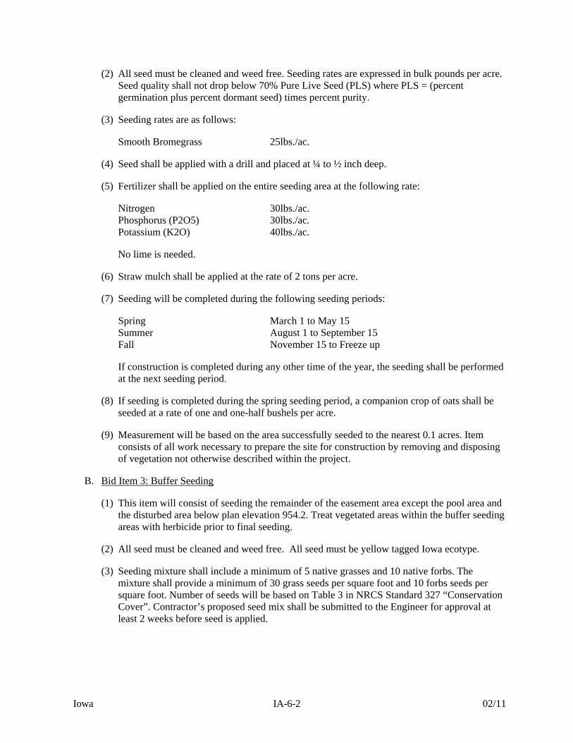
(2) All seed must be cleaned and weed free. Seeding rates are expressed in bulk pounds per acre. Seed quality shall not drop below 70% Pure Live Seed (PLS) where PLS = (percent germination plus percent dormant seed) times percent purity.
(3) Seeding rates are as follows:
Smooth Bromegrass 25lbs./ac.
(4) Seed shall be applied with a drill and placed at ¼ to ½ inch deep.
(5) Fertilizer shall be applied on the entire seeding area at the following rate:
Nitrogen 30lbs./ac. Phosphorus (P2O5) 30lbs./ac. Potassium (K2O) 40lbs./ac.
No lime is needed.
(6) Straw mulch shall be applied at the rate of 2 tons per acre.
(7) Seeding will be completed during the following seeding periods:
Spring March 1 to May 15 Summer August 1 to September 15 Fall November 15 to Freeze up
If construction is completed during any other time of the year, the seeding shall be performed at the next seeding period.
(8) If seeding is completed during the spring seeding period, a companion crop of oats shall be seeded at a rate of one and one-half bushels per acre.
(9) Measurement will be based on the area successfully seeded to the nearest 0.1 acres. Item consists of all work necessary to prepare the site for construction by removing and disposing of vegetation not otherwise described within the project.
B. Bid Item 3: Buffer Seeding
(1) This item will consist of seeding the remainder of the easement area except the pool area and the disturbed area below plan elevation 954.2. Treat vegetated areas within the buffer seeding areas with herbicide prior to final seeding.
(2) All seed must be cleaned and weed free. All seed must be yellow tagged Iowa ecotype.
(3) Seeding mixture shall include a minimum of 5 native grasses and 10 native forbs. The mixture shall provide a minimum of 30 grass seeds per square foot and 10 forbs seeds per square foot. Number of seeds will be based on Table 3 in NRCS Standard 327 “Conservation Cover”. Contractor’s proposed seed mix shall be submitted to the Engineer for approval at least 2 weeks before seed is applied.

Iowa IA-6-3 02/11
(4) Seeding will be completed during the following seeding periods:
Spring April 15 to June 1 Fall November 15 to freeze up
(5) Seed may be applied directly using a no-till native seed drill or prepare a firm seedbed for all other planting methods, as follows:
i) If the land was in soybeans, no additional tillage is required. If the land was in corn or other vegetation, till all areas to be seeded by disking or other approved method; thoroughly loosen and pulverize the soil to a depth of three (3) inches. This may require multiple passes of the disk or other approved equipment.
ii) After the disking operation, and prior to seed application, firm the seedbed with a cultipacker or similar piece of equipment.
(6) No lime or fertilizer will be applied.
(7) Sow seed with the contour using drill set for the specified seeding rates. The drill shall be equipped with double coulter furrow openers. The drill shall be subject to acceptance by Engineer. Overlap each successive seeding pass to ensure complete coverage.
(8) Plant seed no more than one-quarter inch deep; some seed may be seen on the surface after seeding.
(9) Broadcasting by centrifugal-type or hydroseeder broadcasters, or by hand shall also be allowed in areas not accessible to drills or other equipment. Once broadcast, the seed must be covered with soil to a depth no greater than one quarter (1/4) inch by means of hand rakes or other approved methods.
(10) Upon completions of the seeding operation, cultipack the seedbed to provide a positive seed-soil contact. If the drill seeder is equipped with an approved cultipacker or press wheels, separate operations shall not be necessary. The type of cultipacker/seeder to be used shall be subject to acceptance by Engineer.
(11) No mulch will be applied.
(12) Measurement will be based on the area successfully seeded to the nearest 0.1 acres.
Iowa IA-8-1 2/05
NATURAL RESOURCES CONSERVATION SERVICE CONSTRUCTION SPECIFICATION
IA-8 MOBILIZATION AND DEMOBILIZATION
1. SCOPE The work shall consist of the mobilization and demobilization of the Contractor’s forces and equipment necessary for performing the work required under the contract. The work shall not include mobilization and demobilization for specific items of work for which payment is provided elsewhere in the contract. Mobilization will not be considered as work in fulfilling the contract requirement for commencement of work. 2. EQUIPMENT AND MATERIALS Mobilization shall include all activities and costs for transportation of personnel, equipment, and operating supplies to the site; establishment of offices, buildings, and other necessary facilities for the Contractor’s operations at the site; premiums paid for performance and payment bonds, including coinsurance and reinsurance agreements as applicable; and other items specified in Section 4. Demobilization shall include all activities and costs for transportation of personnel, equipment, and supplies not included in the contract from the site; including the disassembly, removal and site cleanup of offices, buildings, and other facilities assembled for this contract. The work includes mobilization and demobilization activities required by the contract at the time of award. If additional mobilization and demobilization activities and costs are required during the performance of the contract as a result of changed, deleted or added items of work for which the contractor is entitled to an adjustment in contract price, compensation of such costs will be included in the price adjustment for the item or items of work changed or added. 3. PAYMENT Payment will be made as the work proceeds, after presentation of invoices by the contractor showing specific mobilization and demobilization costs and evidence of the charges of suppliers, subcontractors, and others. If the total of such payments is less than the lump sum contract price, the unpaid balance will be included in the final contract payment. Payment of the lump sum contract price for mobilization and demobilization will constitute full compensation for the completion of the work. Payment will not be made under this item for the purchase costs of materials having a residual value, the cost of materials to be incorporated in the project, or the purchase costs of operating supplies. 4. ITEMS OF WORK AND CONSTRUCTION DETAILS Items of work to be performed in conformance with this specification and the construction details therefore are:
A. Bid Item 4: Mobilization
(1) This item will consist of mobilizing and demobilizing personnel and equipment in preparation to perform the work within the scope of this contract.

Iowa IA-8-2 2/05
(2) Any work that is necessary to provide access to the site including, but not limited to, grading, temporary culverts, and clearing will be included in this item. When construction is completed access areas will be restored, as close as practical, to its original condition.
(3) Any fence removed for access and / or to provide work area shall be replaced with same or like materials as approved by the engineer.
(4) The Contractor shall exercise caution to minimize the amount of damage caused by the grading and clearing operations.
(5) Portable toilets shall be provided at the construction site and used for the sanitary facilities.
(6) This item shall not include transportation of personnel, equipment and operating supplies within the work limits areas of the contract.
(7) Payment will constitute full compensation for related subsidiary item, Pollution Control (IA-5).
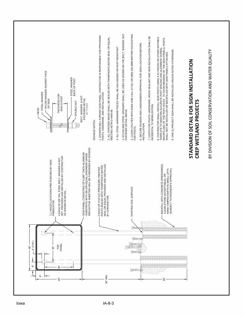
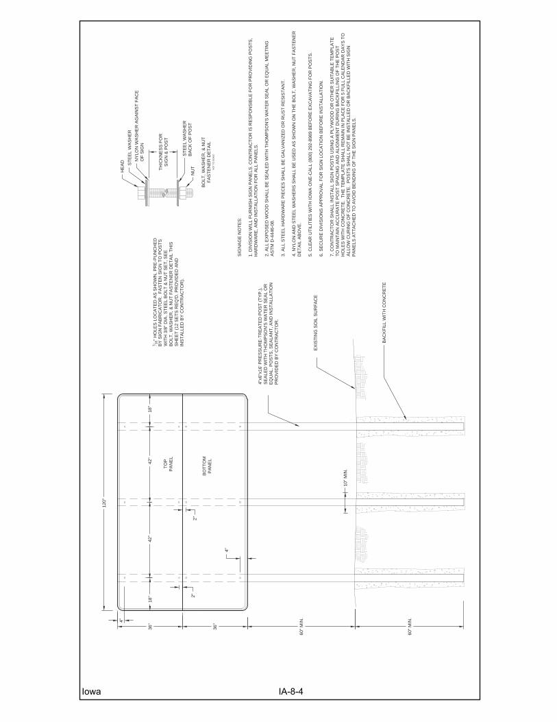
B. Subsidiary Item: Project Sign
(1) This item shall consist of furnishing and installing one large and one small project sign as shown in the sign details; see this section. Locations of the project signs will be determined in the field by the Engineer and the Division.
(2) Furnishing and installing the project signs are considered incidental to Mobilization. No
separate payment will be made for the signs.
STAN
DARD
DET
AIL
FOR
SIG
N IN
STAL
LATI
ON
CREP
WET
LAN
D PR
OJE
CTS
BY D
IVIS
ION
OF
SOIL
CO
NSE
RVAT
ION
AN
D W
ATER
QU
ALIT
Y
EX
IS
TIN
G S
OIL S
UR
FA
CE
7
16
" H
OLE
S LO
CA
TIO
NS
P
RE
-P
UN
CH
ED
B
Y S
IG
N
FA
BR
IC
AT
OR
.
4 E
AC
H O
F 3/8" D
IA
. S
TE
EL B
OLT
, W
AS
HE
R &
N
UT
SE
T P
RO
VID
ED
A
ND
IN
ST
ALLE
D B
Y C
ON
TR
AC
TO
R
AS
S
HO
WN
IN
D
ET
AIL.
SIG
N P
AN
EL C
ON
SIS
TIN
G O
F 0.080" T
HIC
K A
LU
MIN
UM
SU
BS
TR
AT
E W
IT
H 3M
(O
R E
QU
AL) E
NG
IN
EE
R G
RA
DE
RE
FLE
CT
IV
E S
HE
ET
IN
G W
ILL B
E F
UR
NIS
HE
D B
Y D
IV
IS
IO
N.
BA
CK
FILL W
IT
H C
ON
CR
ET
E (P
RE
FE
RR
ED
),
CLE
AN
S
TO
NE
(A
CC
EP
TA
BLE
), O
R
HA
ND
-T
AM
PE
D E
AR
TH
IN
S
MA
LL LIF
TS
(S
UB
JE
CT
T
O E
NG
IN
EE
R'S
A
PP
RO
VA
L)
2 E
AC
H O
F 4"x4"x12' P
RE
SS
UR
E-T
RE
AT
ED
PO
ST
S S
EA
LE
D W
IT
H T
HO
MP
SO
N'S
W
AT
ER
SE
AL O
R E
QU
AL P
RO
VID
ED
A
ND
IN
ST
ALLE
D
BY
C
ON
TR
AC
TO
R.
SIG
NA
GE
N
OT
ES
:
1. D
IV
IS
IO
N W
ILL F
UR
NIS
H S
IG
N P
AN
EL. C
ON
TR
AC
TO
R IS
R
ES
PO
NS
IB
LE
F
OR
P
RO
VID
IN
G
PO
ST
S, H
AR
DW
AR
E, A
ND
IN
ST
ALLA
TIO
N .
2. A
LL E
XP
OS
ED
W
OO
D S
HA
LL B
E S
EA
LE
D W
IT
H T
HO
MP
SO
N'S
W
AT
ER
S
EA
L O
R E
QU
AL
ME
ET
IN
G A
ST
M D
-4446-08.
3. A
LL S
TE
EL H
AR
DW
AR
E P
IE
CE
S S
HA
LL B
E G
ALV
AN
IZ
ED
O
R R
US
T R
ES
IS
TA
NT
.
4. N
YLO
N A
ND
S
TE
EL W
AS
HE
RS
S
HA
LL B
E U
SE
D A
S S
HO
WN
O
N T
HE
B
OLT
, W
AS
HE
R, N
UT
FA
ST
EN
ER
D
ET
AIL A
BO
VE
.
5. C
LE
AR
U
TILIT
IE
S W
IT
H IO
WA
O
NE
-C
ALL A
T 811 O
R (800) 292-8989 B
EF
OR
E E
XC
AV
AT
IN
G
FO
R P
OS
TS
.
6. S
EC
UR
E D
IV
IS
IO
N A
ND
LA
ND
OW
NE
RS
A
PP
RO
VA
L F
OR
S
IG
N LO
CA
TIO
N B
EF
OR
E
IN
ST
ALLA
TIO
N.
7. C
OS
TS
F
OR
P
OS
TS
, H
AR
DW
AR
E, W
OO
D S
EA
LA
NT
A
ND
S
IG
N IN
ST
ALLA
TIO
N S
HA
LL B
E
IN
CID
EN
TA
L T
O M
OB
ILIZ
AT
IO
N.
8. C
ON
TR
AC
TO
R S
HA
LL IN
ST
ALL S
IG
N P
OS
TS
U
SIN
G A
P
LY
WO
OD
O
R O
TH
ER
S
UIT
AB
LE
TE
MP
LA
TE
T
O M
AIN
TA
IN
A
CC
UR
AT
E P
OS
T S
PA
CIN
G A
ND
A
LIG
NM
EN
T D
UR
IN
G
BA
CK
FILLIN
G O
F T
HE
P
OS
T H
OLE
S. T
O A
VO
ID
B
EN
DIN
G O
F T
HE
S
IG
N P
AN
ELS
, P
OS
TS
SH
ALL N
OT
B
E IN
ST
ALLE
D O
R B
AC
KF
ILLE
D W
IT
H S
IG
N P
AN
ELS
A
TT
AC
HE
D.
9. O
NE
(1) P
RO
JE
CT
S
IG
N S
HA
LL B
E IN
ST
ALLE
D U
NLE
SS
N
OT
ED
O
TH
ER
WIS
E.
TO
P
PA
NE
L
9"
30"
48"
9"
30"
3" (T
YP
.)
48" M
IN
.
48"
BO
LT
, W
AS
HE
R, &
N
UT
FA
ST
EN
ER
D
ET
AIL
NO
T T
O S
CA
LE
ST
EE
L W
AS
HE
R
HE
AD
NY
LO
N W
AS
HE
R A
GA
IN
ST
F
AC
E
OF
S
IG
N
ST
EE
L W
AS
HE
R
BA
CK
O
F P
OS
T
DO
UB
LE
N
UT
TH
IC
KN
ES
S F
OR
SIG
N &
P
OS
T
48"
Iowa IA-8-3
EX
IST
ING
SO
IL S
UR
FA
CE
716
" H
OLE
S L
OC
AT
ED
AS
SH
OW
N, P
RE
-PU
NC
HE
DB
Y S
IGN
FA
BR
ICA
TO
R.
FA
ST
EN
SIG
N T
O P
OS
TS
WIT
H 3
/8"
DIA
. ST
EE
L B
OLT
& N
UT
SE
T, S
EE
BO
LT, W
AS
HE
R, &
NU
T F
AS
TE
NE
R D
ET
AIL
TH
ISS
HE
ET
(12
SE
TS
RE
Q'D
. PR
OV
IDE
D A
ND
INS
TA
LLE
D B
Y C
ON
TR
AC
TO
R).
4"x6
"x16
' PR
ES
SU
RE
-TR
EA
TE
D P
OS
T (
TY
P.)
,S
EA
LED
WIT
H T
HO
MP
SO
N'S
WA
TE
R S
EA
L O
RE
QU
AL.
PO
ST
S, S
EA
LAN
T, A
ND
INS
TA
LLA
TIO
NP
RO
VID
ED
BY
CO
NT
RA
CT
OR
.
SIG
NA
GE
NO
TE
S:
1. D
IVIS
ION
WIL
L F
UR
NIS
H S
IGN
PA
NE
LS. C
ON
TR
AC
TO
R IS
RE
SP
ON
SIB
LE F
OR
PR
OV
IDIN
G P
OS
TS
,H
AR
DW
AR
E, A
ND
INS
TA
LLA
TIO
N F
OR
ALL
PA
NE
LS.
2. A
LL E
XP
OS
ED
WO
OD
SH
ALL
BE
SE
ALE
D W
ITH
TH
OM
PS
ON
'S W
AT
ER
SE
AL
OR
EQ
UA
L M
EE
TIN
GA
ST
M D
-444
6-08
.
3. A
LL S
TE
EL
HA
RD
WA
RE
PIE
CE
S S
HA
LL B
E G
ALV
AN
IZE
D O
R R
US
T R
ES
IST
AN
T.
4. N
YLO
N A
ND
ST
EE
L W
AS
HE
RS
SH
ALL
BE
US
ED
AS
SH
OW
N O
N T
HE
BO
LT, W
AS
HE
R, N
UT
FA
ST
EN
ER
DE
TA
IL A
BO
VE
.
5. C
LEA
R U
TIL
ITIE
S W
ITH
IOW
A O
NE
-CA
LL (
800)
292
-898
9 B
EF
OR
E E
XC
AV
AT
ING
FO
R P
OS
TS
.
6. S
EC
UR
E D
IVIS
ION
S A
PP
RO
VA
L F
OR
SIG
N L
OC
AT
ION
BE
FO
RE
INS
TA
LLA
TIO
N.
7. C
ON
TR
AC
TO
R S
HA
LL IN
ST
ALL
SIG
N P
OS
TS
US
ING
A P
LYW
OO
D O
R O
TH
ER
SU
ITA
BLE
TE
MP
LAT
ET
O M
AIN
TA
IN A
CC
UR
AT
E P
OS
T S
PA
CIN
G A
ND
ALI
GN
ME
NT
DU
RIN
G B
AC
KF
ILLI
NG
OF
TH
E P
OS
TH
OLE
S W
ITH
CO
NC
RE
TE
. T
HE
TE
MP
LAT
E S
HA
LL R
EM
AIN
IN P
LAC
E F
OR
5 F
ULL
CA
LEN
DA
R D
AY
S T
OA
LLO
W C
UR
ING
OF
CO
NC
RE
TE
. P
OS
TS
SH
ALL
NO
T B
E IN
ST
ALL
ED
OR
BA
CK
FIL
LED
WIT
H S
IGN
PA
NE
LS A
TT
AC
HE
D T
O A
VO
ID B
EN
DIN
G O
F T
HE
SIG
N P
AN
ELS
.
BO
TT
OM
PA
NE
L
TO
PP
AN
EL
4"
42"
18"
60"
MIN
.
36"
36"
BO
LT, W
AS
HE
R, &
NU
TF
AS
TE
NE
R D
ET
AIL
NO
T T
O S
CA
LE
ST
EE
L W
AS
HE
R
HE
AD N
YLO
N W
AS
HE
R A
GA
INS
T F
AC
EO
F S
IGN
ST
EE
L W
AS
HE
RB
AC
K O
F P
OS
TN
UTTH
ICK
NE
SS
FO
RS
IGN
& P
OS
T
60"
MIN
.
18"
42"
2"
4"
BA
CK
FIL
L W
ITH
CO
NC
RE
TE
2"
120"
10"
MIN
.
Iowa IA-8-4
Iowa IA-9-1 12/14
NATURAL RESOURCES CONSERVATION SERVICE CONSTRUCTION SPECIFICATION
IA-9 SUBSURFACE DRAIN INVESTIGATION, REMOVAL, AND REPAIR
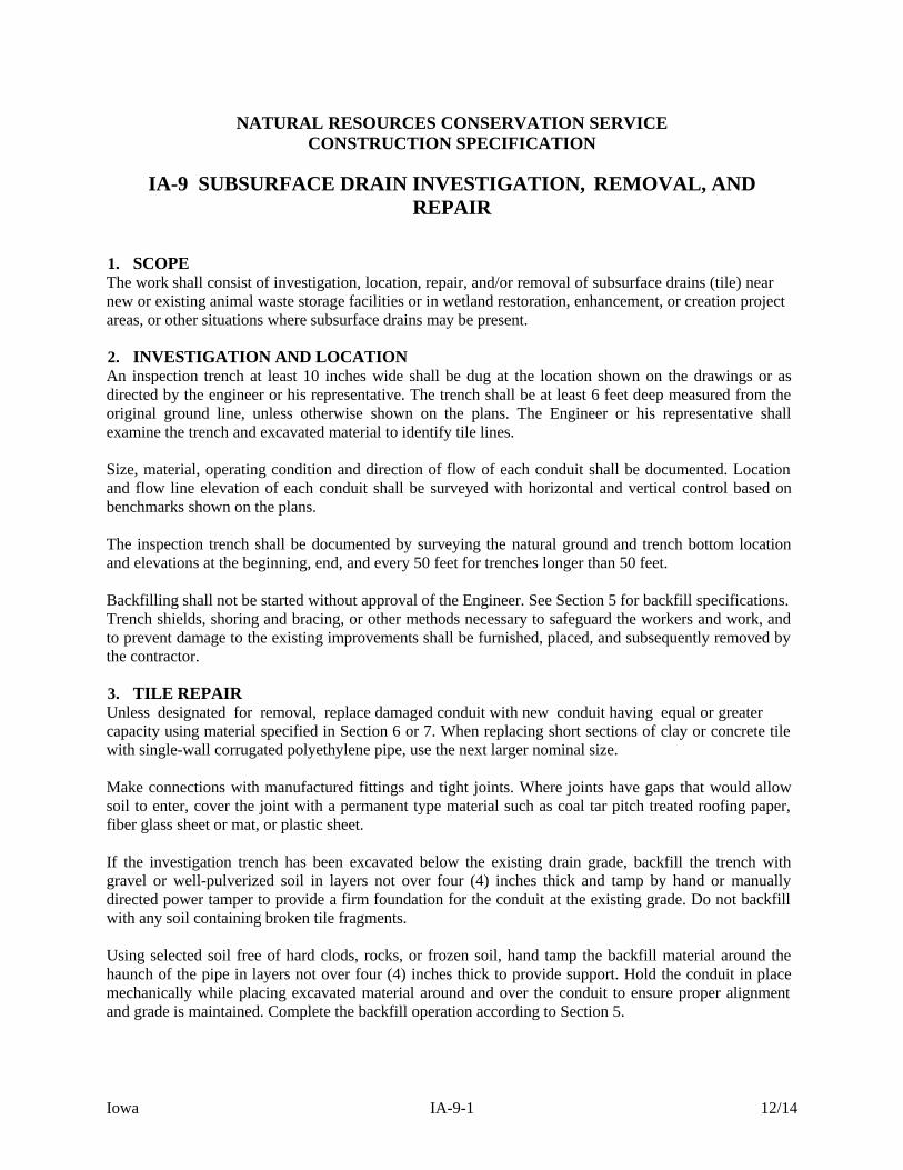
1. SCOPE The work shall consist of investigation, location, repair, and/or removal of subsurface drains (tile) near new or existing animal waste storage facilities or in wetland restoration, enhancement, or creation project areas, or other situations where subsurface drains may be present. 2. INVESTIGATION AND LOCATION An inspection trench at least 10 inches wide shall be dug at the location shown on the drawings or as directed by the engineer or his representative. The trench shall be at least 6 feet deep measured from the original ground line, unless otherwise shown on the plans. The Engineer or his representative shall examine the trench and excavated material to identify tile lines. Size, material, operating condition and direction of flow of each conduit shall be documented. Location and flow line elevation of each conduit shall be surveyed with horizontal and vertical control based on benchmarks shown on the plans. The inspection trench shall be documented by surveying the natural ground and trench bottom location and elevations at the beginning, end, and every 50 feet for trenches longer than 50 feet. Backfilling shall not be started without approval of the Engineer. See Section 5 for backfill specifications. Trench shields, shoring and bracing, or other methods necessary to safeguard the workers and work, and to prevent damage to the existing improvements shall be furnished, placed, and subsequently removed by the contractor. 3. TILE REPAIR Unless designated for removal, replace damaged conduit with new conduit having equal or greater capacity using material specified in Section 6 or 7. When replacing short sections of clay or concrete tile with single-wall corrugated polyethylene pipe, use the next larger nominal size. Make connections with manufactured fittings and tight joints. Where joints have gaps that would allow soil to enter, cover the joint with a permanent type material such as coal tar pitch treated roofing paper, fiber glass sheet or mat, or plastic sheet. If the investigation trench has been excavated below the existing drain grade, backfill the trench with gravel or well-pulverized soil in layers not over four (4) inches thick and tamp by hand or manually directed power tamper to provide a firm foundation for the conduit at the existing grade. Do not backfill with any soil containing broken tile fragments. Using selected soil free of hard clods, rocks, or frozen soil, hand tamp the backfill material around the haunch of the pipe in layers not over four (4) inches thick to provide support. Hold the conduit in place mechanically while placing excavated material around and over the conduit to ensure proper alignment and grade is maintained. Complete the backfill operation according to Section 5.

Iowa IA-9-2 12/14
4. TILE REMOVAL Remove conduits as shown on the plans or directed by the Engineer or his representative, including envelope filter material or other flow enhancing material when present. Cap or plug the open ends of the disconnected conduit to prevent soil entry when the conduit will continue to function downstream, or otherwise shown on the plans. For a minimum distance of two feet around each sealed conduit end, backfill in layers not over four (4) inches thick and tamp by hand or manually directed power tamper to a density equal to or greater than the surrounding undisturbed soil. Do not backfill with any soil containing broken tile fragments, large stones, frozen material, or large dry clods. Where tile are located beneath an existing animal waste facility, remove the tile or fill the entire length of tile with concrete or Portland cement grout as shown on the plans. When tile removal is specified, the owner shall contact the Iowa Department of Natural Resources (IDNR) for permission to remove the drainage tile under the structure. The structure shall be emptied of waste or lowered to a point below the tile prior to its removal. The structure must be retested for percolation and the results submitted to IDNR and approval received prior to reusing the structure. If shown on the plans or directed by the engineer, reroute upstream drain lines so the capacity of the upstream drainage system is maintained. Install conduit in accordance with Iowa Construction Specification IA-46, Tile Drains for Land Drainage. 5. BACKFILL Compact soil around disturbed tile as specified in Section 3 (Tile Repair) and Section 4 (Tile Removal). Keep the backfill within 5 feet of the conduit free from large stones, frozen material, and large dry clods. Unless otherwise shown on the plans, backfill the remainder of the trench as follows:
For trenches located under or near structures, backfill in 12 inch layers and compact each layer to a density equal to or greater than the surrounding undisturbed soil. For other locations, backfill the remainder of each trench with the excavated soil material which shall extend above the ground surface and be well rounded over the trench.
6. MATERIALS Unless otherwise shown on the plans, conduit and fittings used for repair shall conform to the specifications listed in Table 1. Perforated pipe shall have a water inlet area of at least 1 square inch per foot, provided by perforations spaced uniformly along the long axis of the pipe. The perforations shall be circular or slots. Circular perforations shall not exceed 3/16 inch in diameter. Slots shall not be more than 1/8 inch wide.
Iowa IA-9-3 12/14
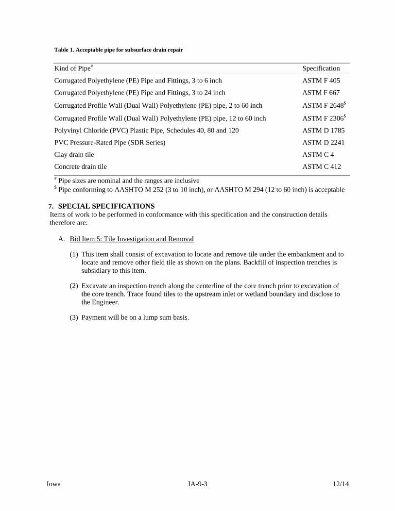
Table 1. Acceptable pipe for subsurface drain repair
Kind of Pipe# Specification
Corrugated Polyethylene (PE) Pipe and Fittings, 3 to 6 inch ASTM F 405
Corrugated Polyethylene (PE) Pipe and Fittings, 3 to 24 inch ASTM F 667
Corrugated Profile Wall (Dual Wall) Polyethylene (PE) pipe, 2 to 60 inch ASTM F 2648$
Corrugated Profile Wall (Dual Wall) Polyethylene (PE) pipe, 12 to 60 inch ASTM F 2306$
Polyvinyl Chloride (PVC) Plastic Pipe, Schedules 40, 80 and 120 ASTM D 1785
PVC Pressure-Rated Pipe (SDR Series) ASTM D 2241
Clay drain tile ASTM C 4
Concrete drain tile ASTM C 412
# Pipe sizes are nominal and the ranges are inclusive $ Pipe conforming to AASHTO M 252 (3 to 10 inch), or AASHTO M 294 (12 to 60 inch) is acceptable
7. SPECIAL SPECIFICATIONS Items of work to be performed in conformance with this specification and the construction details therefore are:
A. Bid Item 5: Tile Investigation and Removal
(1) This item shall consist of excavation to locate and remove tile under the embankment and to locate and remove other field tile as shown on the plans. Backfill of inspection trenches is subsidiary to this item.
(2) Excavate an inspection trench along the centerline of the core trench prior to excavation of the core trench. Trace found tiles to the upstream inlet or wetland boundary and disclose to the Engineer.
(3) Payment will be on a lump sum basis.

Iowa IA-11-1 02/11
NATURAL RESOURCES CONSERVATION SERVICE CONSTRUCTION SPECIFICATION
IA-11 REMOVAL OF WATER
1. SCOPE The work shall consist of the removal of surface water and ground water as needed to perform the required construction in accordance with the plans and specifications. 2. DIVERTING SURFACE WATER The Contractor shall build, maintain and operate all cofferdams, channels, diversions, flumes, sumps, and other temporary protective works needed to divert surface water away from the construction site while construction is in progress. 3. DEWATERING THE CONSTRUCTION SITE Foundations, cutoff trenches, borrow areas and other parts of the construction site shall be dewatered as needed for proper execution of the construction work. The Contractor shall furnish, install, operate and maintain all works and equipment needed to perform the dewatering. 4. EROSION AND POLLUTION CONTROL Removal of water from the construction site, including the borrow areas shall be accomplished in such a manner that erosion and the transmission of sediment and other pollutants are minimized. 5. REMOVAL OF TEMPORARY WORKS After temporary works have served their purposes and before the Contractor leaves the site, they shall be removed. 6. SPECIAL SPECIFICATIONS Items of work to be performed in conformance with this specification and the construction details therefore are:
A. Subsidiary Item: Removal of Water
(1) This item will consist of diverting surface water and dewatering the site as needed for construction. Ground water levels shall be maintained at least 2 feet below the trench bottom for installation of the draw down pipe and water control structure.
(2) No separate payment will be made for Removal of Water.
Iowa IA-13-1 02/11
NATURAL RESOURCES CONSERVATION SERVICE CONSTRUCTION SPECIFICATION
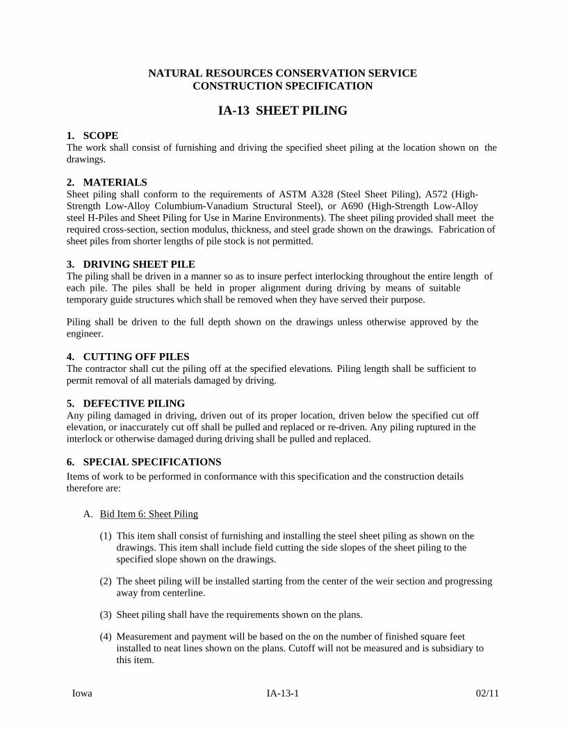
IA-13 SHEET PILING 1. SCOPE The work shall consist of furnishing and driving the specified sheet piling at the location shown on the drawings. 2. MATERIALS Sheet piling shall conform to the requirements of ASTM A328 (Steel Sheet Piling), A572 (High- Strength Low-Alloy Columbium-Vanadium Structural Steel), or A690 (High-Strength Low-Alloy steel H-Piles and Sheet Piling for Use in Marine Environments). The sheet piling provided shall meet the required cross-section, section modulus, thickness, and steel grade shown on the drawings. Fabrication of sheet piles from shorter lengths of pile stock is not permitted. 3. DRIVING SHEET PILE The piling shall be driven in a manner so as to insure perfect interlocking throughout the entire length of each pile. The piles shall be held in proper alignment during driving by means of suitable temporary guide structures which shall be removed when they have served their purpose. Piling shall be driven to the full depth shown on the drawings unless otherwise approved by the engineer. 4. CUTTING OFF PILES The contractor shall cut the piling off at the specified elevations. Piling length shall be sufficient to permit removal of all materials damaged by driving. 5. DEFECTIVE PILING Any piling damaged in driving, driven out of its proper location, driven below the specified cut off elevation, or inaccurately cut off shall be pulled and replaced or re-driven. Any piling ruptured in the interlock or otherwise damaged during driving shall be pulled and replaced. 6. SPECIAL SPECIFICATIONS Items of work to be performed in conformance with this specification and the construction details therefore are:
A. Bid Item 6: Sheet Piling
(1) This item shall consist of furnishing and installing the steel sheet piling as shown on the drawings. This item shall include field cutting the side slopes of the sheet piling to the specified slope shown on the drawings.
(2) The sheet piling will be installed starting from the center of the weir section and progressing away from centerline.
(3) Sheet piling shall have the requirements shown on the plans.
(4) Measurement and payment will be based on the on the number of finished square feet installed to neat lines shown on the plans. Cutoff will not be measured and is subsidiary to this item.

Iowa IA-21-1 07/13
NATURAL RESOURCES CONSERVATION SERVICE CONSTRUCTION SPECIFICATION
IA-21 EXCAVATION
1. SCOPE The work shall consist of the excavation required by the drawings and specifications and disposal of the excavated materials. The cutoff trench and any other required excavations shall be dug to the lines and grades shown on the drawings or as staked in the field. Structure or trench excavations will conform to all safety requirements of OSHA. 2. USE OF EXCAVATED MATERIALS Suitable materials from the specified excavations shall be used in the construction of required permanent earth fill. The suitability of materials for specific purposes shall be determined by the NRCS Inspector. 3. DISPOSAL OF WASTE MATERIAL All surplus or waste material shall be disposed of in areas shown on the drawings or as approved by the NRCS Inspector. The waste material shall be smoothed and sloped to provide drainage. 4. STRUCTURE AND TRENCH EXCAVATION Structure or trench excavations will conform to all safety requirements of OSHA. 5. BORROW EXCAVATION When the quantities of suitable materials obtained from specified excavations are insufficient to construct the specified fills, additional materials shall be obtained from the designated borrow areas as shown on the drawings or as approved by NRCS and the landowner. On wetland projects, borrow shall not be taken from the wetland area within 10 feet of the embankment or as shown on the drawings. Borrow areas shall be excavated and grading completed in a manner to eliminate steep or unstable side slopes or hazardous or unsightly conditions. 6. OVER-EXCAVATION Excavation beyond the specified lines and grades shall be corrected by filling the resulting voids with compacted earthfill, except that if the earth is to become the subgrade for riprap, sand or gravel bedding or drainfill, the voids shall be filled with material conforming to the specifications for the riprap, bedding or drainfill, as appropriate. 7. SPECIAL SPECIFICATIONS Items of work to be performed in conformance with this specification and the construction details therefore are:
A. Bid Item 7: Excavation
(1) Item consists of all work necessary for excavation and finish grading of the pool area, channels, core trench, stilling basins, auxiliary spillway, over excavation for placement of rip rap, and other miscellaneous items required to complete the project.
(2) Item includes hauling excavated material to be used as earthfill or spoiled on site in designated waste areas.
Iowa IA-21-2 07/13
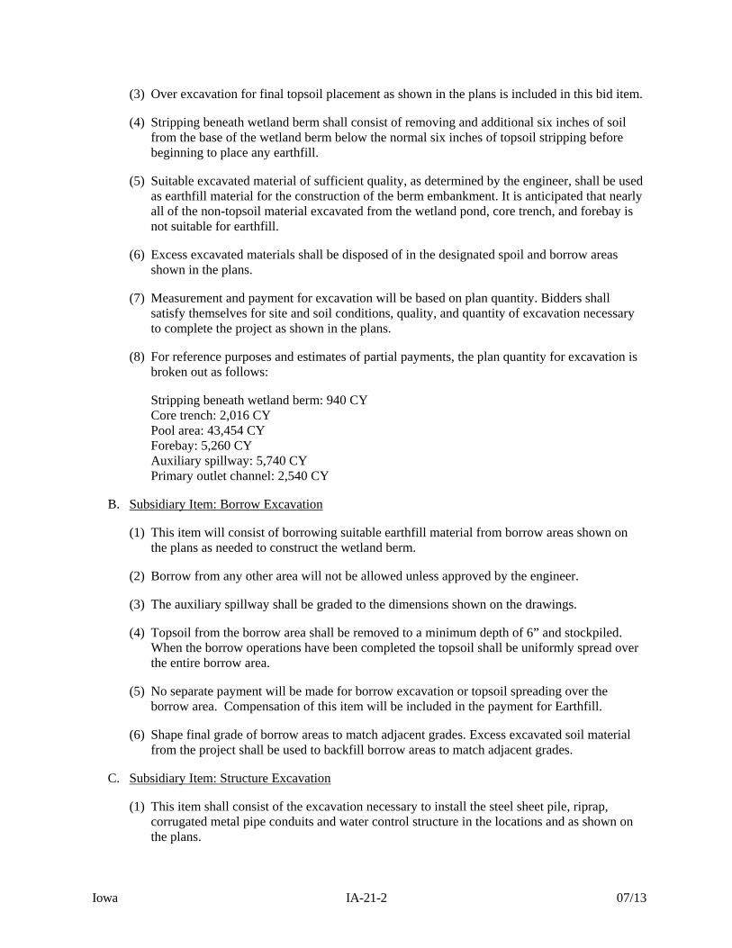
(3) Over excavation for final topsoil placement as shown in the plans is included in this bid item.
(4) Stripping beneath wetland berm shall consist of removing and additional six inches of soil from the base of the wetland berm below the normal six inches of topsoil stripping before beginning to place any earthfill.
(5) Suitable excavated material of sufficient quality, as determined by the engineer, shall be used as earthfill material for the construction of the berm embankment. It is anticipated that nearly all of the non-topsoil material excavated from the wetland pond, core trench, and forebay is not suitable for earthfill.
(6) Excess excavated materials shall be disposed of in the designated spoil and borrow areas shown in the plans.
(7) Measurement and payment for excavation will be based on plan quantity. Bidders shall satisfy themselves for site and soil conditions, quality, and quantity of excavation necessary to complete the project as shown in the plans.
(8) For reference purposes and estimates of partial payments, the plan quantity for excavation is broken out as follows:
Stripping beneath wetland berm: 940 CY Core trench: 2,016 CY Pool area: 43,454 CY Forebay: 5,260 CY Auxiliary spillway: 5,740 CY Primary outlet channel: 2,540 CY
B. Subsidiary Item: Borrow Excavation
(1) This item will consist of borrowing suitable earthfill material from borrow areas shown on the plans as needed to construct the wetland berm.
(2) Borrow from any other area will not be allowed unless approved by the engineer.
(3) The auxiliary spillway shall be graded to the dimensions shown on the drawings.
(4) Topsoil from the borrow area shall be removed to a minimum depth of 6” and stockpiled. When the borrow operations have been completed the topsoil shall be uniformly spread over the entire borrow area.
(5) No separate payment will be made for borrow excavation or topsoil spreading over the borrow area. Compensation of this item will be included in the payment for Earthfill.
(6) Shape final grade of borrow areas to match adjacent grades. Excess excavated soil material from the project shall be used to backfill borrow areas to match adjacent grades.
C. Subsidiary Item: Structure Excavation
(1) This item shall consist of the excavation necessary to install the steel sheet pile, riprap, corrugated metal pipe conduits and water control structure in the locations and as shown on the plans.

Iowa IA-21-3 07/13
(2) No separate payment will be made for Structure Excavation. Compensation for this item will be included in payment for Corrugated Metal Pipe, 15”; Water Control Structure; Sheet Piling; and Riprap.
Iowa IA-23-1 12/15
NATURAL RESOURCES CONSERVATION SERVICE CONSTRUCTION SPECIFICATION
IA-23 EARTHFILL
1. SCOPE The work shall consist of the construction of earth fills required by the drawings and specifications. The completed work shall conform to the lines, grades, and elevations shown on the drawings or as staked in the field. 2. MATERIALS All fill materials shall be obtained from required excavations and designated borrow areas. Fill materials shall contain no sod, brush, roots or other bio-degradable materials. Rocks larger than 6 inches in diameter shall be removed prior to compaction of the fill. 3. FOUNDATION PREPARATION Foundations for earthfill shall be stripped a minimum of 12 inches to remove vegetation and other unsuitable materials. Foundation surfaces shall be scarified to a minimum depth of 2 inches prior to placing fill material. Foundation and abutment surfaces shall not be sloped steeper than 1.5 horizontal to 1 vertical unless otherwise shown on the drawings. 4. PLACEMENT Fill shall not be placed until the required excavation and foundation preparation have been completed and the foundation has been inspected and approved by NRCS. Fill shall not be placed upon a frozen surface, nor shall snow, ice, or frozen material be incorporated in the fill. Adjacent to structures or pipes, fill shall be placed in a manner which will prevent damage. The height of the fill adjacent to structures or pipes shall be increased at approximately the same rate on all sides. The materials used throughout the earth fill shall be essentially uniform. Selective placement shall be as shown on the drawings or approved by NRCS. If the surface of any layer becomes too hard and smooth for proper bond with the succeeding layer, it shall be scarified to a minimum depth of 2 inches before the next layer is placed. The top surfaces of embankments shall be maintained approximately level during construction, except that a cross-slope of approximately 2% shall be maintained to ensure effective drainage. When moving fill material from the borrow area(s) to the embankment by use of bulldozers only, the following steps shall be followed:
Immediately after the borrow material is pushed to the embankment, it shall be spread in horizontal lifts placed parallel to the centerline of the embankment.
Compactive effort will then be applied by operating equipment parallel to the centerline of the fill or
embankment.
Lift thicknesses shall be in strict compliance with Clause 6, below. Sectional fills are not allowed unless they are shown on the construction drawings.
Iowa IA-23-2 12/15
5. CONTROL OF MOISTURE CONTENT The moisture content of the fill material shall be adequate for obtaining the required compaction. Material that is too wet shall be dried to meet this requirement, and material that is too dry shall have water added and mixed until the requirement is met. The moisture content of the fill material shall be such that a ball formed with the hands does not crack or separate when struck sharply with a pencil and will easily ribbon out between the thumb and finger. Earth foundations under and adjacent to concrete structures shall be prevented from drying and cracking before concrete and backfill are placed. The application of water to the fill materials shall be accomplished at the borrow areas insofar as possible. 6. COMPACTION Earth fill shall be compacted by one of the following methods as specified on the plans or in Section 8, Special Specifications. If no method is specified, compaction will be in accordance with Method 1.
Method 1 - Earthfill shall be placed so that the wheels or tracks of the loaded hauling equipment, traveling in a direction parallel to the centerline of fill, pass over the entire surface of each layer being placed. Low ground pressure vehicles shall not be used for this purpose.
Method 2 - Two (2) complete passes of a tamping-type roller will be made over each layer. The roller shall be capable of exerting a minimum force of two hundred (200) pounds per square inch.
Method 3 - Minimum density shall be 90% of the maximum density as determined by ASTM D 698
and as shown on the plans. The maximum thickness of a lift of fill before compaction shall be 9 inches, unless otherwise indicated on the drawings. Fill adjacent to structures, pipe conduits, and appurtenances shall be placed in layers not more than 4 inches thick and compacted to a density equivalent to that of the surrounding fill. Methods used to obtain compaction for fine or coarse grained materials are as follows:
For fine grained materials, hand tamping or manually directed power tampers may be used. Hand compaction only shall be used to compact the earthfill under the bottom half of circular pipes. Manually directed power tampers shall not be used in tight spaces where applying full compactive effort will result in direct contact of the tamper plate with the pipe. Care should be taken so that compaction around the spillway pipe does not cause uplift of the pipe resulting in a void beneath the pipe.
For coarse grained materials (sands and gravels), vibratory plate compactors shall be used for
obtaining compaction. However, hand tamping shall be used to compact the material under the bottom half of circular pipes.
In all cases, follow manufacturer instructions for the specific compaction equipment being used. Heavy equipment shall not be operated within 2 feet of any structure or pipe. Compacting of fill adjacent to concrete structures shall not be started until the concrete is 7 days old.

Iowa IA-23-3 12/15
7. ISLANDS, MOUNDS, AND LOAFING AREAS ON WETLAND RESTORATION, ENHANCEMENT, OR CREATION PROJECTS
Islands shall be randomly located within the wetland area at locations shown on the drawings or as staked in the field. The orientation of island shorelines shall be random with attention given to prevailing winds to limit wave damage. In general, the side of the island with the longest dimension shall be parallel to the prevailing wind direction. Side slopes of islands shall be as shown on the drawings, but in no case shall be steeper than 6 horizontal to 1 vertical. Island shapes shall be irregular.
Loafing areas shall be constructed in the areas shown on the drawings or as staked in the field and shall be graded to drain runoff water. The elevation of at least one loafing area should be above the maximum water level whenever possible. Excavated material not suitable for embankments, wetland dikes, or islands can be used to create mounds or blended into surrounding topography to create a natural appearance. Spoil material shall not be spread on existing wetland areas. Organic soils shall not be used to construct islands, loafing areas, dikes, or embankments. 8. SPECIAL SPECIFICATIONS Items of work to be performed in conformance with this specification and the construction details therefore are:
A. Bid Item 8: Earthfill
(1) This item shall consist of the earthfill necessary to construct the wetland berm including backfill of the stripping excavation and core trench.
(2) Earthfill material shall be from the auxiliary splilway excavation or designated borrow sources unless otherwise approved by the engineer.
(3) Compaction of the wetland berm and core trench shall be Method 2. All other earthfill areas shall be compacted with Method 1.
(4) Measurement and payment for earthfill will be based on plan quantity. Bidders shall satisfy themselves for site and soil conditions, quality, and quantity of earthfill necessary to complete the project as shown in the plans.
(5) For reference purposes and estimates of partial payments, the plan quantity for earthfill is broken out as follows:
Core trench: 2,620 CY Wetland berm: 5,150 CY The quantities listed above reflect the constructed, in-place compacted volumes plus a 30% shrink factor.
B. Subsidiary Item: Backfill of Required Excavation
(1) This item shall consist of backfilling the areas excavated to install the corrugated metal pipe, drawdown structure, and backfill tile removal trench.
(2) Compaction adjacent to the structures shall be as indicated above. All other compaction shall be Method 1 or equivalent.

Iowa IA-23-4 12/15
(3) No separate payment will be made for Backfill of Structure Excavation. Compensation for this item will be included in payment for Corrugated Metal Pipe, 15”; Water Control Structure; and Tile Investigation and Removal.
Iowa IA-24-1 12/15
NATURAL RESOURCES CONSERVATION SERVICE CONSTRUCTION SPECIFICATION
IA-24 DRAINFILL
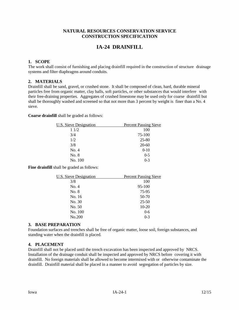
1. SCOPE The work shall consist of furnishing and placing drainfill required in the construction of structure drainage systems and filter diaphragms around conduits. 2. MATERIALS Drainfill shall be sand, gravel, or crushed stone. It shall be composed of clean, hard, durable mineral particles free from organic matter, clay balls, soft particles, or other substances that would interfere with their free-draining properties. Aggregates of crushed limestone may be used only for coarse drainfill but shall be thoroughly washed and screened so that not more than 3 percent by weight is finer than a No. 4 sieve. Coarse drainfill shall be graded as follows:
U.S. Sieve Designation Percent Passing Sieve 1 1/2 1003/4 75-1001/2 25-803/8 20-60No. 4 0-10No. 8 0-5No. 100 0-3
Fine drainfill shall be graded as follows:
U.S. Sieve Designation Percent Passing Sieve 3/8 100No. 4 95-100No. 8 75-95No. 16 50-70No. 30 25-50No. 50 10-20No. 100 0-6No.200 0-3
3. BASE PREPARATION Foundation surfaces and trenches shall be free of organic matter, loose soil, foreign substances, and standing water when the drainfill is placed. 4. PLACEMENT Drainfill shall not be placed until the trench excavation has been inspected and approved by NRCS. Installation of the drainage conduit shall be inspected and approved by NRCS before covering it with drainfill. No foreign materials shall be allowed to become intermixed with or otherwise contaminate the drainfill. Drainfill material shall be placed in a manner to avoid segregation of particles by size.
Iowa IA-24-2 12/15
5. COMPACTION A. Foundation Trench Drain
(1) No compaction will be required beyond that resulting from the placing and spreading
operations.
B. Filter Diaphragm
(1) Each layer of sand material shall be flooded with clean water prior to compaction.
(2) Compaction shall be accomplished while the material is wet from step (1) above.
(3) Each layer shall be compacted by a minimum of 2 passes of a hand directed vibratory plate compactor over the entire layer surface.
(4) Layer thickness shall not exceed 12 inches after compaction.
C. Filter Diaphragm Outlet
(1) Sand material shall be placed so the layer thickness does not exceed 4 inches after compaction.
(2) Each layer shall be compacted by a minimum of 2 passes of a hand directed vibratory plate
compactor over the entire layer surface. 6. SPECIAL SPECIFICATIONS Items of work to be performed in conformance with this specification and the construction details therefore are:
A. Bid Item 9: Drainfill
(1) Item consists of all work necessary to construct the filter diaphragm and filter outlet for the drawdown pipe as shown in the plans.
(2) Measurement and payment for drainfill will be based on plan quantity. The filter diaphragm and filter diaphragm outlet shall be comprised of fine drainfill as noted above. Bidders shall satisfy themselves for the quantity of drainfill necessary to complete the project as shown in the plans.
(3) For reference purposes and estimates of partial payments, the plan quantity for drainfill is broken out as follows:
Filter Diaphragm (Fine Drainfill): 7 CY Filter Diaphragm Outlet (Fine Drainfill): 28 CY Filter Diaphragm Outlet (Course Drainfill): 2 CY
The quantities listed above reflect the constructed, in-place compacted volumes.

Iowa IA-26-1 02/11
NATURAL RESOURCES CONSERVATION SERVICE CONSTRUCTION SPECIFICATION
IA-26 TOPSOILING
1. SCOPE The work shall consist of salvaging topsoil from borrow areas or required excavations and spreading it on the exposed disturbed areas.
2. QUALITY OF TOPSOIL Topsoil shall consist of friable surface soil reasonably free of grass, roots, weeds, sticks, stones, or other foreign materials.
3. EXCAVATION After the site has been cleared and grubbed, the topsoil shall be removed from borrow areas and required excavation areas to the depth as shown on the drawings. Topsoil shall be stockpiled at locations approved by NRCS.
4. SPREADING Spreading shall not be done when the ground or topsoil is frozen, excessively wet, or otherwise in a condition detrimental to the work. Surfaces designated to be covered shall be lightly scarified just prior to the spreading operation. Where compacted fills are designated to be covered by topsoil, the topsoil shall be placed concurrently with the fill and shall be bonded to the compacted fill with the equipment. Topsoil shall be placed to the minimum depth shown on the drawings. After the spreading operation is completed, the surface shall be finished to a reasonably smooth surface.
5. SPECIAL SPECIFICATIONS Items of work to be performed in conformance with this specification and the construction details therefore are:
A. Bid Item 10: Topsoil, Strip, Salvage, Respread
(1) Item consists of all work necessary to strip, salvage, stockpile, and respread a minimum of 6 inches of topsoil as the final surface layer to meet the grades shown in the plans that will receive seeding, including excavated areas within the wetland pool above elevation 951.2 feet.
(2) Measurement and payment for topsoil will be based on plan quantity. Bidders shall satisfy themselves for site and soil conditions, quality, and quantity of topsoil necessary to complete the project as shown in the plans.
(3) Maximum allowable topsoil stockpile height shall be 5 feet. Topsoil stripping beneath stockpile is not required.
Iowa IA-31-1 02/13
NATURAL RESOURCES CONSERVATION SERVICE CONSTRUCTION SPECIFICATION
IA-31 CONCRETE
1. SCOPE The work shall consist of furnishing, forming, placing, finishing, and curing Portland cement concrete including steel reinforcement. 2. MATERIALS Portland Cement shall conform to ASTM C 150 and shall be Type I or Type II. Fine Aggregates shall conform to ASTM C 33 and shall be composed of clean, uncoated grains of material. Coarse Aggregates shall be gravel or crushed stone conforming to ASTM C 33 and shall be clean, hard, durable and free from clay or coating of any character. The maximum size of coarse aggregate shall be 1 1/2 inches or as shown on the drawings. Water shall be clean and free from injurious amounts of oil, acid, salt, alkali, organic matter, or other deleterious substances. Air entraining agent shall conform to ASTM C 260. Fly ash may be used as a partial substitution for Portland cement and shall be in strict compliance with ASTM C 618, Class F or C. The loss by ignition shall not exceed 4.0 percent. Blast-furnace slag may be used as a partial substitution for Portland cement and shall be in conformance with ASTM C 989 for ground granulated blast-furnace slag (GGBF slag). Water-reducing admixtures shall conform to ASTM C 494 and may be the following types:
1. Type A - Water-reducing admixture 2. Type D - Water-reducing and retarding admixture 3. Type F - Water-reducing, high range admixture (superplasticizer). 4. Type G - water-reducing, high range, and retarding admixture (superplasticizer).
Type D or G admixture may be used when the air temperature is over 80 degrees F. at the time of mixing and/or placement.
Calcium Chloride or other antifreeze compounds or accelerators will not be allowed. Preformed expansion joint filler shall be a commercially available product made of bituminous, sponge rubber or closed cell foam materials with a minimum thickness of 1/2 inch. Reinforcing steel shall be free from loose rust, oil, grease, paint, or other deleterious matter. Reinforcing steel shall conform to one or more of the following:
1. Reinforcing Bars - ASTM A 615 or A 996 , Grade 40 or greater, deformed. 2. Welded Wire Fabric - ASTM A 185 or A 497.
Iowa IA-31-2 02/13
Waterstops shall be either metallic or nonmetallic. Metallic waterstops shall be fabricated from sheets of copper or galvanized steel. Nonmetallic waterstops shall be made of natural or synthetic rubber or vinyl chloride polymer or copolymer. Rubber, polymer and copolymer waterstops shall have ribbed or bulb-type anchor flanges and a hollow tubular center bulb, unless otherwise shown on the drawings. All waterstops shall be of the sizes shown on the drawings. Curing compound shall be a liquid membrane-forming compound suitable for spraying on the concrete surface. The curing compound shall meet the requirements of ASTM C 309 Type 2 (white pigmented).
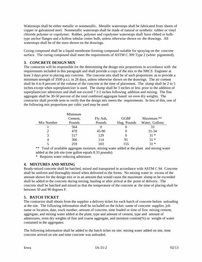
3. CONCRETE DESIGN MIX The contractor will be responsible for the determining the design mix proportions in accordance with the requirements included in this paragraph and shall provide a copy of the mix to the NRCS Engineer at least 3 days prior to placing any concrete. The concrete mix shall be of such proportions as to provide a minimum strength of 3500 p.s.i. in 28 days, unless otherwise shown on the drawings. The air content shall be 4 to 8 percent of the volume of the concrete at the time of placement. The slump shall be 2 to 5 inches except when superplasticizer is used. The slump shall be 3 inches or less prior to the addition of superplasticizer admixture and shall not exceed 7 1/2 inches following addition and mixing. The fine aggregate shall be 30-50 percent of the total combined aggregate based on oven dry weights. The contractor shall provide tests to verify that the design mix meets the requirements. In lieu of this, one of the following mix proportions per cubic yard may be used:
Mix Number
Minimum Cement, Pounds
Fly Ash, Pounds
GGBF Slag, Pounds
Maximum ** Water, Gallons
1 564 0 0 33 2 470 45-90 0 31-34 3 517 129 0 31 * 4 366 114 91 31 * 5 259 103 155 31 *
** Total of available aggregate moisture, mixing water added at the plant and mixing water added at the job site (one gallon equals 8.33 pounds). * Requires water reducing admixture.
4. MIXTURES AND MIXING Ready-mixed concrete shall be batched, mixed and transported in accordance with ASTM C 94. Concrete shall be uniform and thoroughly mixed when delivered to the forms. No mixing water in excess of the amount shown for the design mix or in an amount that would cause the maximum slump to be exceeded shall be added to the concrete during mixing, hauling or after arrival at the point of delivery. The concrete shall be batched and mixed so that the temperature of the concrete at the time of placing shall be between 50 and 90 degrees F.
5. BATCH TICKET The contractor shall obtain from the supplier a delivery ticket for each batch of concrete before unloading at the site. The following information shall be included on the ticket: name of concrete supplier, job name or location, date, truck number, amount of concrete, time loaded or time of first mixing cement, aggregate, and mixing water added at the plant, type and amount of cement, type and amount of admixtures, oven dry weights of fine and coarse aggregate, and moisture content(%) or weight of water contained in the aggregates. The following information shall be added to the batch ticket on site: mixing water added on site, time concrete arrived on site and time concrete was unloaded.
Iowa IA-31-3 02/13
Upon completion of the concrete placement, copies of all batch tickets shall be provided to NRCS. 6. REINFORCING STEEL Before reinforcement is placed, the surfaces of the bars or mesh shall be cleaned to remove any loose, flaky rust, mill scale, oil, grease, or other foreign substances. After placement, the reinforcement shall be maintained in a clean condition until it is completely embedded in the concrete. Reinforcing bars shall be cut and bent according to ACI Standard 315. Tack welding of bars shall not be permitted. Reinforcement shall be accurately placed as shown on the drawings and secured in position in a manner that will prevent its displacement during placement of concrete. Metal chairs, metal hangers, metal spacers or concrete chairs shall be used to support reinforcement. Precast concrete chairs shall be manufactured from concrete equal in quality to the concrete being placed. Precast concrete chairs shall be moist at the time concrete is placed Splices of reinforcing bars shall be made only at the locations shown on the drawings, unless otherw ise approved by the NRCS Engineer. All reinforcing splices and placement shall be in accordance with ACI 318 and shown on the drawings. After placement of the reinforcement, concrete shall not be placed until the reinforcement has been inspected and approved by NRCS.
7. PREPARATION OF FORMS AND SUBGRADE Prior to placement of concrete, the forms and subgrade shall be free of woodchips, sawdust, debris, water, ice, snow, extraneous oil, mortar, or other harmful substances or coatings. Any oil on the reinforcing steel or other surfaces required to be bonded to the concrete shall be removed. All surfaces shall be firm and damp prior to placing concrete. Placement of concrete on mud, dried earth, uncompacted fill, or frozen subgrade will not be permitted. The forms and associated false-work shall be substantial and unyielding and shall be constructed so that the finished concrete will conform to the specified dimensions and elevations. Forms will be mortar tight. Forms with torn surfaces, worn edges, dents or other defects will not be used. Forms shall be coated with a nonstaining form release agent before being set into place. Excess form coating material shall not stand in puddles in the forms or come in contact with the steel reinforcement or hardened concrete against which fresh concrete is to be placed. Form accessories to be partially or wholly embedded in the concrete, such as ties and hangers, shall be of a commercially manufactured type. Non fabricated wire shall not be used. Form ties shall be constructed so that the ends or end fasteners can be removed without causing spalling at the surface of the concrete. Metal form ties used within the forms on structures with a total volume of concrete exceeding fifteen cubic yards shall be equipped with cones or other devices that permit their removal to a depth of at least one inch without damage to the concrete. The holes resulting from cones and other devices shall be patched in accordance with Section 9. Form ties except those specifically covered by the preceding paragraph shall be broken off flush with the formed surface. Any surface areas which have been spalled or otherwise damaged shall be repaired in accordance with Section 9. Steel tying and form construction adjacent to new concrete shall not be started until concrete has cured at least 12 hours.
Iowa IA-31-4 02/13
Concrete joints shall be of the type and at the locations shown on the drawings. Splices in metal waterstops shall be brazed, welded or overlapped and bolted. Splices in nonmetallic waterstops shall be cemented or joined as recommended by the manufacturer.
8. PLACING CONCRETE Concrete shall not be placed until the subgrade, forms, and steel reinforcement have been inspected and approved by the NRCS Inspector. Any deficiencies are to be corrected before the concrete is delivered for placement. Concrete shall be delivered to the site and discharged into the forms within 1 1/2 hours after the introduction of the cement to the aggregates. When a superplasticizer is used, the concrete shall be discharged within the manufacturer's recommended time limit for discharge after addition of the admixture. In hot weather or under conditions contributing to quick setup of the concrete, discharge of the concrete shall be accomplished in 45 minutes unless a set-retarding admixture is used, in which case the manufacturer's recommended time limit will apply. Addition of water at the job site may be done at the beginning of placement of each load of concrete in order to obtain allowable slump, provided that the maximum water content and water/cement ratio in the design mix is not exceeded. Addition of water will not be permitted after placement of the load has started. The concrete shall be deposited as closely as possible to its final position in the forms and shall be worked into corners and around reinforcement and other embedded items in a manner which prevents segregation. Formed concrete shall be deposited in layers 24 inches or less in depth and shall be continuously deposited so that no concrete will be deposited on concrete which has hardened sufficiently to cause the formation of “cold joints”. Concrete containing superplasticizer shall be placed in lifts not exceeding 5 feet in depth. If the surface layer of concrete sets during placement to the degree that it will not flow and merge with the succeeding layer when tamped or vibrated, the contractor shall discontinue placing concrete and install a construction joint. Construction joints shall be completed as shown on the drawings or by one of the following methods:
1. The joint shall be constructed using a 6 inch wide by 1/4 inch steel plate. The surfaces of the construction joint shall be prepared by washing and scrubbing with a wire brush or wire broom to expose coarse aggregate. The steel plate shall be embedded 3” in the concrete.
2. The joint surface shall be cleaned to expose coarse aggregate by sandblasting or air-water cutting
after the concrete has gained sufficient strength to prevent displacement of the coarse aggregate or cement fines. The surface of the concrete shall not be cut so deep as to undercut the coarse aggregate. The joint shall be washed to remove all loose material after cutting.
The surfaces of all construction joints shall be kept continuously moist for at least 1 hour prior to placement of the new concrete. The new concrete shall be placed directly on the cleaned and washed surface. New concrete shall not be placed until the hardened concrete has cured at least 12 hours. Concrete shall not be dropped more than 5 feet vertically unless suitable equipment is used to prevent segregation. Concrete containing superplasticizer shall not be dropped more than 12 feet vertically. Immediately after the concrete is placed in the forms, it shall be consolidated by vibration, spading or hand tamping as necessary to insure smooth surfaces and dense concrete. Care should be taken not to over-vibrate concrete containing superplasticizer. Vibration shall not be supplied directly to the

Iowa IA-31-5 02/13
reinforcing steel, the forms or concrete which has hardened to the degree that it does not insure a monolithic bond with the preceding layer, The use of vibrators to transport concrete in the forms or conveying equipment will not be permitted. 9. FORM REMOVAL AND FINISHING Forms shall be left in place for at least 24 hours after placing concrete. Forms shall be removed in such a way as to prevent damage to the concrete. Supports shall be removed in a manner that will permit concrete to take the stresses due to its own weight uniformly and gradually. Immediately after removal of the forms, concrete which is honey combed, damaged or otherwise defective shall be repaired or replaced. All cavities or depressions resulting from form tie removal shall be patched with a non-shrink grout, mortar mix or epoxy-type sealer. Non-shrink grout consists of 1 part cement and 2-1/2 parts sand that will pass a No. 16 sieve. Only enough water shall be added to produce a filling which is at the point of becoming rubbery when the material is solidly packed. All repaired and patched areas shall be cured as required in Section 10.
10. CURING Concrete shall be cured for a period of not less than 7 consecutive days by one of the following approved methods:
A. Membrane Curing: Concrete shall be cured with white pigmented curing compound. The compound shall be sprayed on moist concrete as soon as free water has disappeared, but shall not be applied to any surface until patching, repairs and finishing of that surface are completed. Curing compound shall not be applied to surfaces requiring bond to subsequently placed concrete, such as construction joints, shear plates, reinforcing steel, and other embedded items. Surfaces subjected to heavy rainfall or running water within 3 hours after curing compound has been applied or surfaces damaged by subsequent construction operations during the curing period, shall be reapplied in the same manner as the original application.
B. Moist Curing: Concrete shall be cured by maintaining all surfaces continuously wet for the entire curing period.
C. Cover: Adequately cover an exposed structure with burlap mats, or other material and continually soak with water.
11. BACKFILLING Backfilling may begin when the curing period has ended. Backfill against the structure will be placed in no more than 4-inch layers and compacted by hand tamping or with manually directed power tampers or plate vibrators. Layers compacted in this manner shall extend not less than 2 feet from any part of the concrete structure.
12. HOT AND COLD WEATHER CONCRETING
When the atmospheric temperature may be expected to drop below 40o F. at the time concrete is delivered to the work site , during placement, or at any time during curing period, concrete shall be mixed, placed and protected in accordance with ACI Standard 306, “Recommended Practice for Cold Weather Concreting.” When climatic or other conditions are such that the temperature of the concrete may reasonably be
expected to exceed 90o F. at the time of delivery to the work site, during placement or during the first 24 hours after placement, concrete shall be mixed, placed and protected in accordance with ACI Standard
Iowa IA-31-6 02/13
305, “Recommended Practice for Hot Weather Concreting.” 13. SPECIAL SPECIFICATIONS Items of work to be performed in conformance with this specification and the construction details therefore are:
A. Subsidiary Item: Concrete
(1) This item shall consist of furnishing and placing poured concrete and reinforced concrete as shown in the plans.
(2) No separate payment will be made for concrete. Compensation for this item will be included in the payment for the drawdown structure.
Iowa IA-46-1 02/13
NATURAL RESOURCES CONSERVATION SERVICE CONSTRUCTION SPECIFICATION
IA-46 TILE DRAINS FOR LAND DRAINAGE
1. SCOPE The work shall consist of furnishing and installing drainage pipe (tubing) and tile and the necessary fittings and appurtenances. 2. MATERIALS Concrete drain tile shall conform to the requirements of ASTM C 412 and clay drain tile shall conform to the requirements of ASTM C 4. Corrugated polyethylene (PE) pipe (tubing) and fittings shall conform to ASTM F 405 (3” to 6”) or F 667 (3” to 24”), as appropriate. Corrugated profile wall (dual wall) polyethylene (PE) pipe shall meet or exceed the requirements of ASTM F 2648 (2” to 60”) or ASTM F 2306 (12” to 60”). Pipe conforming to AASHTO M 252 (3” to 10”), or AASHTO M 294 (12” to 60”) is acceptable. Perforated tubing shall have a water inlet area of at least 1 square inch per foot, provided by perforations spaced uniformly along the long axis of the tubing. The perforations shall be circular or slots. Circular perforations shall not exceed 3/16 inch in diameter. Slots shall not be more than 1/8 inch wide. 3. EXCAVATION Unless otherwise specified, excavation for and subsequent installation of each drain line shall begin at the outlet end and progress upstream. The trench or excavation for the conduit shall be constructed to the line, depth, cross section, and grade shown on the drawings, or as directed by the NRCS Inspector. The trench bottom shall be smooth and free of exposed rock. If rock is encountered in the trench bottom, over-excavate the trench and place at least 6 inches of compacted earth or sand bedding in the trench to bring it up to the conduit grade. If not otherwise shown on the drawings, trench width at the top of the conduit shall be the minimum required to permit installation and provide bedding conditions suitable to support the load on the conduit, but with not less than three (3) inches of clearance on each side of the conduit. Maximum trench width shall be the conduit diameter plus 12 inches measured at the top of the conduit, unless approved bedding is installed. Trench shields, shoring and bracing, or other methods, necessary to safeguard the workers and work, and to prevent damage to the existing improvements shall be furnished, placed, and subsequently removed by the contractor. Plow installation is allowed. Minimum trench width shall be two (2) inches wider than the conduit on each side. Grade control and bedding conditions shall be closely inspected during plow installation. Boulders, cobbles, or cemented soils can cause the plow to jump and lose grade. These hardpoints can also puncture or dimple and deform the pipe. 4. PREPARING THE BEDDING Unless otherwise specified, no filter or envelope is required. In stable soils, the bottom of the trench shall be shaped to form a semicircular, trapezoidal, or 90-degree “V” groove in its center. The groove shall be shaped to fit the size of tile. The 90-degree “V” groove shall not be used on conduits greater than 6 inches
Iowa IA-46-2 02/13
in diameter. If the bottom of the trench does not provide a sufficiently stable or firm foundation for the drain tile, a sand-gravel mix or other approved materials shall be used to stabilize the bottom of the trench. 5. FILTER OR ENVELOPE MATERIAL When a filter is specified, the shape of the bottom of the trench, gradation and the thickness of the filter or envelope material to be placed around the conduit will be as shown on the drawings. The envelope or filter material shall be placed in the bottom of the trench just prior to the laying of the conduit. The conduit shall then be laid and the envelope or filter material placed over the conduit. 6. PLACEMENT AND JOINT CONNECTIONS All drains shall be laid to grade. Joints between lateral concrete and clay drain tiles shall vary with soil type as follows:
a. Peat and muck - 1/4 inch preferred, 3/8 inch maximum b. Clay - 1/8 inch preferred, 1/4 inch maximum c. Silt and loam - 1/16 inch preferred, 1/8 inch maximum d. Sand - tightest possible fit.
Joints between main drain tile, which serve only to collect and transport drainage water from lateral tile lines, should be the tightest fit possible. Where the joint width exceeds the maximum above, the joint shall be covered with a permanent type material such as coal tar pitch treated roofing paper, fiber glass sheet or mat, or plastic sheet. After placement and blinding of plastic tubing, but prior to backfilling, sufficient time shall elapse to allow the tubing to reach the ambient temperature of the trench. All split fittings shall be securely tied with nylon cord before backfill is placed. When corrugated plastic tubing is used, no more than 5% stretch will be allowed. 7. CONNECTIONS Lateral connections will be made with manufactured appurtenances (wyes, tees, etc.) comparable in strength and durability with the specified conduit unless otherwise shown on the drawings. Existing drain lines not shown on the drawings but encountered during installation shall be bridged across the trench or connected into the new line, as directed by NRCS. Connections with the outlet pipe shall be made watertight. 8. OUTLETS A continuous section of non-perforated conduit at least 20 feet long shall be used at the outlet. At least two- thirds of the outlet pipe shall be buried in the ditch bank, and the cantilever section must extend to the toe of the ditch side slope or the side slope protected from erosion. Acceptable materials for use at the outlet include the following:
a. Corrugated metal pipe, galvanized or aluminum, 16 gauge minimum; b. Smooth steel pipe with a minimum wall thickness of 3/16 inch; c. Smooth plastic pipe, polyvinyl chloride (PVC), with a SDR of 26 or less or schedule 40 or
heavier; or

Iowa IA-46-3 02/13
d. Corrugated profile wall (dual wall) polyethylene pipe (PE). All plastic (PVC) and polyethylene pipe (PE) outlets shall include ultra-violet stabilizer. PVC and PE pipe outlets shall not be used where burning vegetation on the outlet ditch bank is likely to create a fire hazard. The outlet shall be equipped with a flap-gate type rodent guard. 9. BLINDING After the conduit is placed in the excavated groove, friable material from the sides of the trench shall be placed around the conduit, completely filling the trench to a depth of not less than six (6) inches over the top of the conduit. For material to be suitable it must not contain hard clods, rocks, frozen soil, or fine material which will cause a silting hazard to the drain. Conduit placed during any one day shall be blinded by the end of the day's work. 10. BACKFILLING The backfilling of the trench shall be completed as rapidly as consistent with the soil conditions. Automatic backfilling machines may be used. Backfill shall extend above the ground surface and be well rounded over the trench. Unless otherwise shown on the plans, in mineral soils, the minimum depth of cover over subsurface drains shall be 2.5 feet. In organic soils, the minimum depth of cover after initial subsidence shall be 3.0 feet. 11. SPECIAL SPECIFICATIONS Items of work to be performed in conformance with this specification and the construction details therefore are:
A. Bid Item 11: Drain Tile, 8”
Bid Item 12: Drain Tile, 12” Bid Item 13: Drain Tile, 15”
(1) Item consists of all work necessary to furnish and install corrugated polyethylene drain tile as shown on the plans. Install non-perforated pipe within the easement boundary. Corrugated metal pipe outlets are covered under their respective bid items.
(2) Payment will be based on linear feet of drain tile installed in the field. Unit price shall include all necessary appurtenances, fittings, adaptors, and connections to dissimilar pipe.
B. Subsidiary Item: Backfilling to increase cover
(1) Backfilling tile to achieve the desired minimum cover with excess soil from the wetland excavation is subsidiary to the excavation bid item.

Iowa IA-51-1 02/11
NATURAL RESOURCES CONSERVATION SERVICE CONSTRUCTION SPECIFICATION
IA-51 CORRUGATED METAL PIPE CONDUITS
1. SCOPE The work shall consist of furnishing and placing circular, arched or elliptical corrugated metal pipe and the necessary fittings. 2. MATERIALS Metallic-coated steel corrugated pipe and fittings shall be zinc-coated or aluminized, Type 2, and shall conform to the requirements of ASTM A 760 and A 929 for the specified type and size of pipe. Aluminum corrugated pipe shall conform to the requirements of ASTM B 745 for the specified type and size of pipe. All pipe is subject to the following additional requirements:
A. When polymer coating is specified, pipe, coupling bands and anti-seep collars shall be coated in accordance with ASTM A 762. All riveted joints shall be caulked as described in paragraph B.
B. Pipe with annular corrugations shall be furnished with caulked seams. Riveted pipe joints shall be caulked with a bituminous mastic material during fabrication to provide a watertight joint. All circumferential and longitudinal seams shall be caulked before riveting. This shall be accomplished by applying a uniform bead of the mastic compound to the inner lap surface before riveting such that when the rivets are in place, all voids are filled and a coating of mastic is between the lap surfaces. The inner surface of coupling bands shall be asphalt coated in the field prior to installation. A neoprene gasket having a minimum thickness of 3/8 inch and a minimum width of 7 inches may be used in lieu of mastic coated coupling bands.
C. Welded or lock seams in helical corrugated pipe are considered to be watertight.
D. When close riveted pipe is specified: (1) the pipe shall be fabricated so that the rivet spacing in the circumferential seams shall not exceed 3 inches, except that 12 rivets will be sufficient to secure the circumferential seams in 12-inch pipe, and (2) in those portions of the longitudinal seams that will be covered by the coupling bands, the rivets shall have finished flat heads or the rivets and holes shall be omitted and the seams shall be connected by welding to provide a minimum of obstruction to the seating off the coupling bands.
E. Double riveting or double spot welding of pipe less than 42 inches in diameter may be required. If specified, the riveting or welding shall be done in the manner specified for pipe 42 inches or greater in diameter.
3. COUPLING BANDS Coupling bands shall meet the requirements of the table below or have detailed drawings submitted for approval by the State Conservation Engineer. Coupling bands shall be of the same minimum thickness (gage) as the pipe being connected.
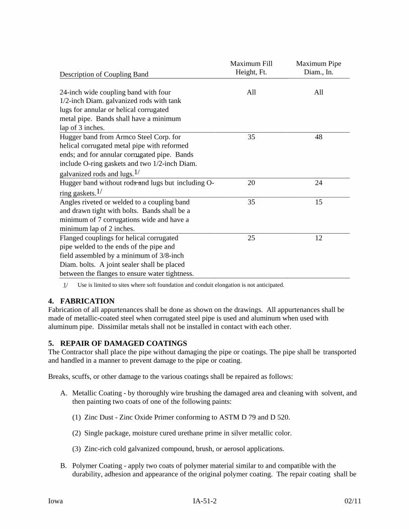
Iowa IA-51-2 02/11
Description of Coupling Band
Maximum Fill Height, Ft.
Maximum Pipe Diam., In.
24-inch wide coupling band with four
All
All
1/2-inch Diam. galvanized rods with tank lugs for annular or helical corrugated metal pipe. Bands shall have a minimum lap of 3 inches. Hugger band from Armco Steel Corp. for 35 48 helical corrugated metal pipe with reformed ends; and for annular corrugated pipe. Bands include O-ring gaskets and two 1/2-inch Diam.
galvanized rods and lugs.1/
Hugger band without rods and lugs but including O-
ring gaskets.1/
20 24
Angles riveted or welded to a coupling band 35 15 and drawn tight with bolts. Bands shall be a minimum of 7 corrugations wide and have a minimum lap of 2 inches. Flanged couplings for helical corrugated 25 12 pipe welded to the ends of the pipe and field assembled by a minimum of 3/8-inch Diam. bolts. A joint sealer shall be placed between the flanges to ensure water tightness.
1/ Use is limited to sites where soft foundation and conduit elongation is not anticipated. 4. FABRICATION Fabrication of all appurtenances shall be done as shown on the drawings. All appurtenances shall be made of metallic-coated steel when corrugated steel pipe is used and aluminum when used with aluminum pipe. Dissimilar metals shall not be installed in contact with each other. 5. REPAIR OF DAMAGED COATINGS The Contractor shall place the pipe without damaging the pipe or coatings. The pipe shall be transported and handled in a manner to prevent damage to the pipe or coating. Breaks, scuffs, or other damage to the various coatings shall be repaired as follows:
A. Metallic Coating - by thoroughly wire brushing the damaged area and cleaning with solvent, and then painting two coats of one of the following paints:
(1) Zinc Dust - Zinc Oxide Primer conforming to ASTM D 79 and D 520. (2) Single package, moisture cured urethane prime in silver metallic color. (3) Zinc-rich cold galvanized compound, brush, or aerosol applications.
B. Polymer Coating - apply two coats of polymer material similar to and compatible with the durability, adhesion and appearance of the original polymer coating. The repair coating shall be

Iowa IA-51-3 02/11
a minimum thickness of 0.010 (10 mils) after drying and shall bond securely to the pipe. 6. LAYING AND BEDDING THE PIPE The pipe shall be laid to the line and grade shown on the drawings and shall be firmly and uniformly bedded throughout its entire length. Details of the bedding are as shown on the drawings. The pipe shall be laid with the outside laps of circumferential joints pointing upstream and with longitudinal laps on the sides at approximately the vertical mid-height of the pipe. Field welding of corrugated galvanized steel pipe will not be permitted. The pipe sections shall be joined with coupling bands. 7. BACKFILLING Special care shall be taken during backfill operations not to disturb the grade and alignment. The pipe shall be tied down or loaded sufficiently during backfilling around the sides to prevent its being lifted from the bedding. Backfill material shall have sufficient moisture so that optimum compaction can be obtained. Backfill around the pipe shall be placed in layers not more than 4 inches thick before compaction. Each layer of backfill shall be compacted with power tampers, hand tampers, or plate vibrators to the same density requirements as specified for the adjacent embankment. Backfill over and around the pipe shall be brought up uniformly on all sides. The passage of earth moving equipment will not be allowed over the pipe until backfill has been placed above the top of the pipe surface to a depth of two (2) feet. 8. SPECIAL SPECIFICATIONS Items of work to be performed in conformance with this specification and the construction details therefore are:
A. Bid Item 14: Corrugated Metal Pipe, 10” x 20’ Outlet Bid Item 15: Corrugated Metal Pipe, 15” x 20’ Outlet Bid Item 16: Corrugated Metal Pipe, 18” x 20’ Outlet Bid Item 17: Corrugated Metal Pipe, 15” Bid Item 18: Water Control Structure
(1) This item will consist of providing and installing the corrugated metal pipe, corrugated metal pipe aprons, corrugated metal pipe tile outlets, and water control structure as shown on the drawings.
(2) Pipe shall be closed riveted caulk seam (CRCS) round pipe with 2 2/3” x ½” annular corrugations and shall conform to ASTM A 760.
(3) Provide detailed shop drawings of the water control structure and appurtenances. Water control structure to include the following:
i) 48” diameter riser pipe with 15” diameter stubs. Riser pipe to be 14 gage, CRCS pipe with 2 2/3” X 1/2” annular corrugations. Stub pipe to be 16 gage CRCS pipe of same corrugations, 2’ minimum length.
ii) Embed riser pipe, 3” minimum, into poured concrete base. Concrete base shall have a minimum thickness of 6” and extend a minimum of 6” horizontally around edge of riser. No separate payment for concrete will be made for the concrete base and should be
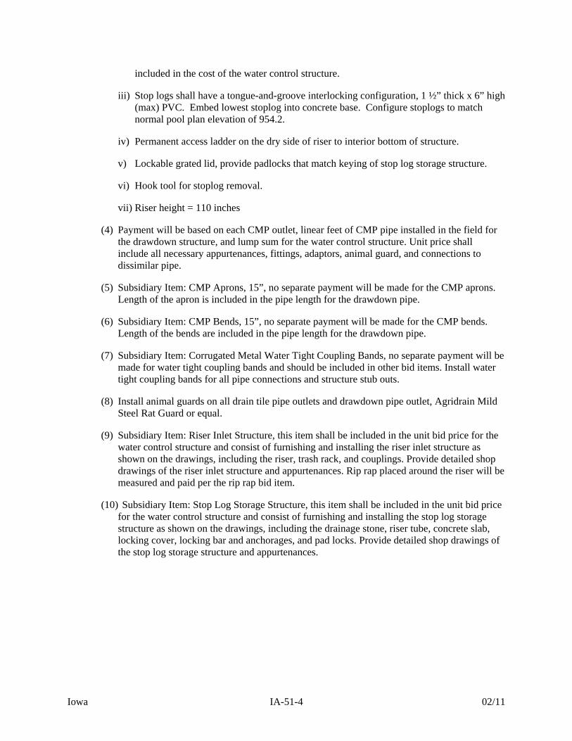
Iowa IA-51-4 02/11
included in the cost of the water control structure.
iii) Stop logs shall have a tongue-and-groove interlocking configuration, 1 ½” thick x 6” high (max) PVC. Embed lowest stoplog into concrete base. Configure stoplogs to match normal pool plan elevation of 954.2.
iv) Permanent access ladder on the dry side of riser to interior bottom of structure.
v) Lockable grated lid, provide padlocks that match keying of stop log storage structure.
vi) Hook tool for stoplog removal.
vii) Riser height = 110 inches
(4) Payment will be based on each CMP outlet, linear feet of CMP pipe installed in the field for the drawdown structure, and lump sum for the water control structure. Unit price shall include all necessary appurtenances, fittings, adaptors, animal guard, and connections to dissimilar pipe.
(5) Subsidiary Item: CMP Aprons, 15”, no separate payment will be made for the CMP aprons. Length of the apron is included in the pipe length for the drawdown pipe.
(6) Subsidiary Item: CMP Bends, 15”, no separate payment will be made for the CMP bends. Length of the bends are included in the pipe length for the drawdown pipe.
(7) Subsidiary Item: Corrugated Metal Water Tight Coupling Bands, no separate payment will be made for water tight coupling bands and should be included in other bid items. Install water tight coupling bands for all pipe connections and structure stub outs.
(8) Install animal guards on all drain tile pipe outlets and drawdown pipe outlet, Agridrain Mild Steel Rat Guard or equal.
(9) Subsidiary Item: Riser Inlet Structure, this item shall be included in the unit bid price for the water control structure and consist of furnishing and installing the riser inlet structure as shown on the drawings, including the riser, trash rack, and couplings. Provide detailed shop drawings of the riser inlet structure and appurtenances. Rip rap placed around the riser will be measured and paid per the rip rap bid item.
(10) Subsidiary Item: Stop Log Storage Structure, this item shall be included in the unit bid price for the water control structure and consist of furnishing and installing the stop log storage structure as shown on the drawings, including the drainage stone, riser tube, concrete slab, locking cover, locking bar and anchorages, and pad locks. Provide detailed shop drawings of the stop log storage structure and appurtenances.

Iowa IA-61-1 12/15
NATURAL RESOURCES CONSERVATION SERVICE CONSTRUCTION SPECIFICATION
IA-61 LOOSE ROCK RIPRAP
1. SCOPE The work shall consist of the construction of loose rock riprap revetments, structures and blankets, including filter layers or bedding where specified.
2. MATERIALS Rock for loose rock riprap, filter layers or bedding shall come from sources approved by NRCS. The rock shall be excavated, selected and handled as necessary to meet the quality and grading requirements of this specification and the construction drawings. Individual rock fragments shall be dense, sound and free from cracks, seams and other defects conducive to accelerated weathering. The rock fragments shall be angular to sub rounded in shape. The least dimension of an individual rock fragment shall not be less than 1/3 the greatest dimension of the fragment unless otherwise specified on the construction drawings.
3. SUBGRADE PREPARATION The subgrade surfaces on which the riprap or bedding is to be placed shall be cut or filled and graded to the lines and grades shown on the drawings. When fill to subgrade lines is required, it shall consist of approved materials and shall be compacted to a density equal to the adjacent existing soil material. Rock materials shall not be placed until the foundation preparation is completed and the subgrade surfaces have been inspected and approved by NRCS.
4. EQUIPMENT-PLACED ROCK RIPRAP Rock shall be placed by equipment on the surfaces and to the depths specified. The riprap shall be constructed to the full thickness in one operation and in such a manner as to avoid serious displacement of the underlying materials. The rock shall be delivered and placed in a manner that will insure that the riprap in place shall be reasonably homogeneous with the larger rocks uniformly distributed and firmly in contact, one to another, with the smaller rocks and spalls filling the voids between the larger rocks. Placement of rock shall begin at the bottom of the slope or downstream end of the structure. Riprap shall be placed in a manner to prevent damage to structures. Hand placing will be required to the extent necessary to prevent damage to adjacent structures.
5. HAND-PLACED RIPRAP Rock shall be placed by hand on the surfaces and to the depths specified. It shall be securely bedded with the larger rocks firmly in contact, one to another. Spaces between the larger rocks shall be filled with smaller rocks and spalls. Smaller rocks shall not be grouped as a substitute for larger rock. Flat slab rock shall be laid on edge unless otherwise specified. Placement of rock shall begin at the bottom of the slope or downstream end of the structure. 6. FILTER LAYERS OR BEDDING When the drawings specify filter layers or bedding beneath riprap, the filter or bedding material shall be spread uniformly on the prepared subgrade surfaces to the depth specified. Compaction of filter layers or bedding will not be required, but the surface of such layers shall be finished reasonably free of mounds, dips or windrows.
Iowa IA-61-2 12/15
7. SPECIAL SPECIFICATIONS Items of work to be performed in conformance with this specification and the construction details therefore are:
A. Bid Item 19: Riprap
(1) This item shall consist of furnishing and placing the rock riprap in the stilling basin downstream of the steel sheet pile structure, immediately upstream of the steel sheet pile and bank stabilization, as shown on the drawings.
(2) Rock shall be Class E Revetment Stone as defined by Iowa Department of Transportation.
(3) All riprap shall be screened by running the stone over a grizzly or plate screen with a minimum opening of 8 inches. This operation shall be done at the quarry. The portion of the stone that is removed by the screening operation will not be acceptable for use as riprap.
(4) Payment will be based on tons of riprap delivered and placed on site as measured by certified weight tickets. Measurement will be to the nearest 0.1 tons. Provide weight tickets to the engineer.
Iowa IA-62-1 02/11
NATURAL RESOURCES CONSERVATION SERVICE CONSTRUCTION SPECIFICATION
IA-62 CONCRETE GROUT FOR RIPRAP
1. SCOPE The work shall consist of furnishing, transporting, and placing concrete grout in the construction of grouted rock riprap sections as shown on the drawings.
2. MATERIALS Cement shall be Type I or Type II Portland cement conforming to ASTM C 150. Fly ash shall be in strict compliance with ASTM C 618, Class F or C. It may be used as a partial substitution for Portland cement for amounts not to exceed 20 percent of the total amount of cementitious material in the grout. The loss by ignition shall not exceed 4.0 percent. Fine aggregate shall conform to ASTM C 33 and shall be composed of clean, uncoated grains of material. Water shall be clean and free of harmful chemicals. Air entraining admixtures shall conform to ASTM C 260.
3. GROUT MIX The grout mix shall be as follows:
a) Cement: 10 sacks or 940 pounds per cubic yard b) Fine concrete aggregate: 2,100 pounds per cubic yard c) Water: 45 gallons per cubic yard or enough to provide a thick creamy consistency d) Air content: 6 to 10 percent.
When ready-mixed grout is furnished, the contractor shall furnish to NRCS a delivery ticket showing the time of loading and the quantities of materials used for each load of grout mix. No mixing water in excess of the amount called for in the grout mix shall be added during mixing, hauling or after arrival of the mix at the delivery point.
4. CONVEYING AND PLACING Grout mix shall be delivered to the site and placed within 1 1/2 hours after the introduction of the cement to the aggregates. In hot weather or under conditions contributing to quick setup of the grout mix, discharge of the concrete shall be accomplished in 45 minutes unless a set-retarding admixture is used, in which case the manufacturer's recommended time limit will apply. Grout mix shall not be dropped more than 5 feet vertically unless suitable equipment is used to prevent segregation. The grout mix shall not be placed until the rock riprap has been inspected and approved. Rock to be grouted shall be kept wet for at least 2 hours immediately prior to grouting. Grout shall not be placed in standing or flowing water. The grout shall be consolidated by spading or mechanical vibration. The grout shall not be forced to flow laterally to its final location. The average rate of grout application shall be 5.4 cubic feet per square yard of riprap (0.6 cubic feet per square foot).
Iowa IA-62-2 02/11
8. CURING CONCRETE Concrete shall be cured for 7 days by either:
a) Applying white pigmented curing compound at a rate of 1 gallon per 150 square feet or as recommended by the manufacturer.
b) Water soak exposed surface for the entire 7 days. c) Cover with burlap, mats or other material and maintain in a moist condition. d) Cover with four (4) mil plastic sheeting while concrete is still wet.
Grout mix shall not be placed when daily minimum temperatures are expected to be lower than 40 degrees F unless facilities are provided to maintain the temperature of the materials at 50 to 90 degrees F during the placement and curing period. Grout may not be placed on frozen surfaces. When freezing conditions are expected, rock shall be heated to 50 to 90 degrees F for at least 24 hours prior to placing grout.
9. SPECIAL SPECIFICATIONS Items of work to be performed in conformance with this specification and the construction details therefore are:
A. Bid Item 20: Concrete Grout
(1) This item shall consist of furnishing, placing, and curing concrete grout on those portions of the riprap shown in the plans.
(2) The grout shall be consolidated into the voids with the use of concrete vibrator. A smooth surface is not to be created by the grouting operation. Concrete should also fill the annular space between the riprap and the face of the sheet pile wall, no voids are allowed.
(3) Grouting operation shall not be performed except in the presence of the Engineer.
(4) Measurement and payment for concrete grout will be based on plan quantity. Plan quantity was based on the average grout rate shown above for the area of grouted riprap show in the plans. Bidders shall satisfy themselves for the quantity of concrete grout necessary to complete the project as shown in the plans.

Iowa IA-81-1 02/11
NATURAL RESOURCES CONSERVATION SERVICE CONSTRUCTION SPECIFICATION
IA-81 METAL FABRICATION AND INSTALLATION
1. SCOPE The work shall consist of furnishing, fabricating, and installing metalwork including metal parts of composite structures.
2. MATERIALS Steel shall be of structural quality. Finished surfaces shall be smooth and true to assure proper fit. Bolts, nuts, washers, rods, rivets, etc., shall be of a material equal to the steel being fastened. 3. PROTECTIVE COATINGS Protective coatings will consist of either galvanizing or painting and shall be applied by the fabricator. Galvanizing shall consist of a zinc coating by the hot dip process, except that bolts, nuts, and washers may have an electrodeposited zinc coating. Paint System for this specification shall consist of the application of one coat of Epoxy Polyamide Primer (lead and chromate free) and one or more coats of Epoxy Polyamide (intermediate or finish), lead free. When finished, it will have a minimum dry film thickness of 8.0 mils.
4. FABRICATION Materials shall be carefully fabricated as shown on the drawings. The fabrication shall be smooth and true to assure proper fit. Galvanized items shall not be cut, welded, or drilled after the zinc coating is applied.
5. ERECTION The metal shall be erected true and plumb, closely conforming to the drawings.
6. SPECIAL SPECIFICATIONS Items of work to be performed in conformance with this specification and the construction details therefore are:
A. Subsidiary Item: Waler
(1) This item will consist of furnishing and installing the waler as shown on the drawings. Steel channel shall be A36 structural steel.
(2) All nuts, bolts, and washers shall be galvanized, cadmium plated, or stainless steel.
(3) No separate payment will be made for the Waler. Compensation for this item will be included in payment for Sheet Piling.

Iowa IA-95-1 02/11
NATURAL RESOURCES CONSERVATION SERVICE CONSTRUCTION SPECIFICATION
IA-95 GEOTEXTILE
1. SCOPE This work shall consist of furnishing all materials, equipment, and labor necessary for the installation of geotextile. 2. MATERIAL QUALITY Geotextile shall be manufactured from synthetic long chain or continuous polymeric filaments or yarns, having a composition of at least 95 percent, by weight, of polypropylene, polyester or polyvinylidene-chloride. The geotextile shall be formed into a stable network of filaments or yarns that retain their relative position to each other, are inert to commonly encountered chemicals and are resistant to ultraviolet light, heat, hydrocarbons, mildew, rodents and insects. Unless otherwise specified, the class and type of geotextile shall be as shown on the drawings and shall meet the requirements for materials that follow:
a. Woven Geotextile shall conform to the physical properties listed in Table 1. The woven geotextile shall be manufactured from monofilament yarns that are woven into a uniform pattern with distinct and measurable openings. The geotextile shall be manufactured so that the yarns will retain their relative position with regard to each other. The yarns shall contain stabilizers and/or inhibitors to enhance their resistance to ultraviolet light or heat exposure. The edges of the material shall be selvaged or otherwise finished to prevent the outer yarn from unraveling.
b. Nonwoven Geotextile shall conform to the physical properties listed in Table 2. Nonwoven geotextile shall be manufactured from randomly oriented fibers that have been mechanically bonded together by the needle-punched process. In addition, one side may be slightly heat bonded. Thermally bonded, nonwoven geotextile, in addition to mechanically bonded, nonwoven geotextile, may be used for Road Stabilization. The filaments shall contain stabilizers and/or inhibitors to enhance their resistance to ultraviolet light or heat exposure.
c. The geotextile shall be shipped in rolls wrapped with a protective covering to keep out mud, dirt, dust, debris and direct sunlight. Each roll of geotextile shall be clearly marked to identify the brand, type and production run.
3. STORAGE Prior to use, the geotextile shall be stored in a clean dry place, out of direct sunlight, not subject to extremes of either hot or cold, and with the manufacturer's protective cover in place. Receiving, storage, and handling at the job site shall be in accordance with the requirements in ASTM D 4873. 4. SURFACE PREPARATION The surface on which the geotextile is to be placed shall be graded to the neat lines and grades as shown on the drawings. The surface shall be reasonably smooth and free of loose rock and clods, holes, depressions, projections, muddy conditions and standing or flowing water (unless otherwise shown on the drawings). 5. PLACEMENT Prior to placement of the geotextile, the soil surface will be inspected for quality assurance of design and construction. The geotextile shall be placed on the approved prepared surface at the locations and in
Iowa IA-95-2 02/11
accordance with the details shown on the drawings. The geotextile shall be unrolled along the placement area and loosely laid (not stretched) in such a manner that it will conform to the surface irregularities when material is placed on or against it. The geotextile may be folded and overlapped to permit proper placement in the designated area. The geotextile shall be joined by overlapping a minimum of 18 inches (unless otherwise specified), and secured against the underlying foundation material. Securing pins, approved and provided by the geotextile manufacturer, shall be placed along the edge of the panel or roll material to adequately hold it in place during installation. Pins shall be steel or fiberglass formed as a "U", "L", or "T" shape or contain "ears" to prevent total penetration. Steel washers shall be provided on all but the "U" shaped pins. The upstream or up-slope geotextile shall overlap the abutting down-slope geotextile. At vertical laps, securing pins shall be inserted through both layers along a line through approximately the midpoint of the overlap. At horizontal laps and across slope laps, securing pins shall be inserted through the bottom layer only. Securing pins shall be placed along a line approximately 2 inches in from edge of the of the placed geotextile at intervals not to exceed 12 feet unless otherwise specified. Additional pins shall be installed as necessary and where appropriate, to prevent any undue slippage or movement of the geotextile. The use of securing pins will be held to the minimum necessary. Pins are to be left in place unless otherwise specified. Should the geotextile be torn or punctured, or the overlaps disturbed, as evidenced by visible geotextile damage, subgrade pumping, intrusion, or grade distortion, the backfill around the damaged or displaced area shall be removed and restored to the original approved condition. The repair shall consist of a patch of the same type of geotextile being used, overlaying the existing geotextile. The patch shall extend a minimum of 2 feet from the edge of any damaged area. The geotextile shall not be placed until it can be anchored and protected with the specified covering within 48 hours or protected from exposure to ultraviolet light. In no case shall material be dropped on uncovered geotextile from a height greater than 3 feet. 6. SPECIAL SPECIFICATIONS Items of work to be performed in conformance with this specification and the construction details therefore are:
A. Bid Item 21: Geotextile
(1) This item shall consist of furnishing and placing geotextile on all earth surfaces that contact the rock riprap as shown on the drawings.
(2) Geotextiles shall be Class I nonwoven as described herein.
(3) The geotextile shall be placed with the long dimension parallel to the channel.
(4) Measurement and payment will be based on geotextile installed in the field. Overlap and cutoff material will not be measured.
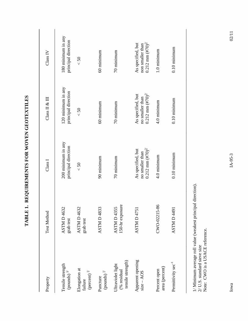
TA
BL
E1.
RE
QU
IRE
ME
NT
SF
OR
WO
VE
N G
EO
TE
XT
ILE
S
Iow
a IA
-95-
302
/11
Pro
pert
y T
est M
etho
d C
lass
I
Cla
ss I
I &
III
C
lass
IV
T
ensi
le s
tren
gth
(pou
nds)
1/
A
STM
D 4
632
grab
test
20
0 m
inim
um in
any
pr
inci
pal d
irec
tion
12
0 m
inim
um in
any
pr
inci
pal d
irec
tion
18
0 m
inim
um in
any
pr
inci
pal d
irec
tion
Elo
ngat
ion
at
AST
M D
463
2 <
50
< 5
0 <
50
fail
ure
(per
cent
) 1/
grab
test
Pun
ctur
e A
STM
D 4
833
90 m
inim
um
60 m
inim
um
60 m
inim
um
(pou
nds)
1/
Ultr
avio
let l
ight
A
STM
D 4
355
70 m
inim
um
70 m
inim
um
70 m
inim
um
(% r
esid
ual
150-
hr e
xpos
ure
te
nsil
e st
reng
th)
App
aren
t ope
ning
A
STM
D 4
751
As
spec
ifie
d, b
ut
As
spec
ifie
d, b
ut
As
spec
ifie
d, b
ut
size
– A
OS
no
sm
alle
rth
an0.
212
mm
(#7
0)2/
no s
mal
ler
than
0.21
2 m
m (
#70)
2/
non
smal
ler
than
0.21
2 m
m (
#70)
2/
Perc
ent o
pen
CW
O-0
2215
-86
4.0
min
imum
4.
0 m
inim
um
1.0
min
imum
ar
ea (
perc
ent)
Perm
ittiv
ity s
ec-1
A
STM
D 4
491
0.10
min
imum
0.
10 m
inim
um
0.10
min
imum
1/ M
inim
um a
vera
ge r
oll v
alue
(w
eake
st p
rinc
ipal
dir
ecti
on).
2/
U.S
. sta
ndar
d si
eve
size
N
ote:
CW
O is
a U
SAC
E r
efer
ence
.

Iow
a IA
-95-
402
/11
TA
BL
E2.
RE
QU
IRE
ME
NT
SF
OR
NO
NW
OV
EN
GE
OT
EX
TIL
ES
Pro
pert
y T
est M
etho
d C
lass
I
Cla
ss I
I C
lass
III
C
lass
IV
3/
Ten
sile
str
engt
h (p
ound
s) 1/
A
STM
D 4
632
grab
test
18
0 m
inim
um
12
0 m
inim
um
90
min
imum
115
min
imum
Elo
ngat
ion
at
fail
ure
(%)
1/
AST
M D
463
2 >
50
> 5
0 >
50
> 5
0
Pun
ctur
e (p
ound
s)
AST
M D
483
3 80
min
imum
60
min
imum
40
min
imum
40
min
imum
Ultr
avio
let l
ight
A
STM
D 4
355
70 m
inim
um
70 m
inim
um
70 m
inim
um
70 m
inim
um
(% r
esid
ual
150-
hr e
xpos
ure
te
nsil
e st
reng
th)
App
aren
t ope
ning
si
ze –
AO
S A
STM
D 4
751
As
spec
ifie
d m
ax. #
40
2/
As
spec
ifie
d m
ax. #
40
2/
As
spec
ifie
d m
ax. #
40
2/
As
spec
ifie
d m
ax. #
40
2/
Perm
ittiv
ity s
ec-1
A
STM
D 4
491
0.70
min
imum
0.
70 m
inim
um
0.70
min
imum
0.
10 m
inim
um
1/ M
inim
um a
vera
ge r
oll v
alue
(w
eake
st p
rinc
ipal
dir
ecti
on).
2/ U
.S. s
tand
ard
siev
e si
ze
3/ H
eat-
bond
ed o
r re
sin
bond
ed g
eote
xtil
e m
ay b
e us
ed f
or c
lass
es I
II a
nd I
V.
The
y ar
e pa
rtic
ular
ly w
ell s
uite
d to
cla
ss I
V.
Nee
dle
punc
hed
geot
exti
les
are
requ
ired
for
all
oth
er c
lass
es.