national type evaluation program (ntep) weighing … type evaluation program (ntep) weighing sector...
TRANSCRIPT

NTEP 2014 Interim Meeting Agenda
Weighing Sector Meeting Summary
NTEP - 1
National Type Evaluation Program (NTEP)
Weighing Sector Meeting Summary
August 27-28, 2013 / Albany, NY
INTRODUCTION
The charge of the NTEP Weighing Sector is important in providing appropriate type evaluation criteria based on
specifications, tolerances and technical requirements of NIST Handbook 44 Specifications, Tolerances, and Other
Technical Requirements for Weighing and Measuring Devices Sections 1.10. General Code, 2.20 Scales, 2.22
Automatic Bulk Weighing Systems, and 2.24 Automatic Weighing Systems. The Sector’s recommendations will be
presented to the National Type Evaluation Program (NTEP) Committee each January for approval and inclusion in
NCWM Publication 14 Technical Policy, Checklists, and Test Procedures for national type evaluation.
The Sector is also called upon occasionally for technical expertise in addressing difficult NIST Handbook 44 issues
on the agenda of National Conference on Weights and Measures (NCWM) Specifications and Tolerances (S&T)
Committee. Sector membership includes industry, NTEP laboratory representatives, technical advisors and the
NTEP Administrator. Meetings are held annually, or as needed and are open to all NCWM members and other
registered parties.
Suggested revisions are shown in bold face print by striking out information to be deleted and underlining
information to be added. Requirements that are proposed to be nonretroactive are printed in bold faced italics.
Table A
Table of Contents
Title of Contents Page
INTRODUCTION ....................................................................................................................................................... 1
CARRY-OVER ITEMS .............................................................................................................................................. 3
Recommended Changes to NCWM Publication 14 Based on Actions at the 2013 NCWM Annual 1.
Meeting .................................................................................................................................................... 3 1.a. Item 320-1 S.6.4. Railway Track Scales and Appendix D – Definitions....................................... 3 1.b. Item 320-4 Appendix C – Units of Mass (ton) .............................................................................. 6
Acceptable Symbols/Abbreviations to Display the CC Number Via a Device’s User Interface ........... 10 2.
DES Section 70. - Performance and Permanence Tests for Railway Track Scales Used to Weigh In-3.
Motion .................................................................................................................................................... 14 NCWM Publication 14 Load Cell Table 6 – Summary Table Examples ............................................... 15 4.
NEW ITEMS .............................................................................................................................................................. 19
Item 360-7 NIST Handbook 44 Appendix D – Definitions: Remote Configuration Capability ............ 19 5.
NCWM Publication 14 DES Section 76 Digital Controller Element for Load Cells Checklists and Test 6.
Procedures .............................................................................................................................................. 21 NCWM Publication 14 DES Checklists and Test Procedures Section 1 Marking – Applicable to 7.
Indicating, Weighing/Load-Receiving Elements and Complete Scales ................................................. 22 NCWM Publication 14 Load Cells - National Type Evaluation Program Terminology for Load Cell 8.
Parameters .............................................................................................................................................. 23 Identification of Certified Software ....................................................................................................... 24 9.
Software Protection / Security ................................................................................................................ 25 10.
Software Maintenance and Reconfiguration .......................................................................................... 29 11.
ATTACHMENTS ...................................................................................................................................................... 31
Appendix A - 2013 NTEP Weighing Sector Attendees (to be included in the Sector report) .......................... 31

NTEP 2014 Interim Meeting Agenda
Weighing Sector Meeting Summary
NTEP - 2
Table B
Glossary of Acronyms and Terms
Acronym Term Acronym Term
ABWS Automatic Bulk Weighing Systems NEWMA Northeastern Weights and Measures
Association
AREMA American Railway Engineering
Maintenance-of-Way Association NTEP National Type Evaluation Program
AWS Automatic Weighing Systems OIML International Organization of Legal
Metrology
CC Certificate of Conformance OWM Office of Weights and Measures
DES Digital Electronic Scales R Recommendation
LMD Liquid Measuring Device S&T Specifications and Tolerances
Committee
MC Measurement Canada SMA Scale Manufacturers Association
MRA Mutual Recognition Agreement WS National Type Evaluation Program
Weighing Sector
NCWM National Conference on Weights
and Measures

NTEP 2014 Interim Meeting Agenda
Weighing Sector Meeting Summary
NTEP - 3
Details of All Items
(In order by Reference Key)
CARRY-OVER ITEMS
Recommended Changes to NCWM Publication 14 Based on Actions at the 2013 NCWM 1.
Annual Meeting
Mr. Harshman, National Institute of Standards and Technology (NIST) Technical Advisor, provided the Sector with
specific recommendations for incorporating test procedures and checklist language based upon actions of the 2013
NCWM Annual Meeting. The Sector was asked to briefly discuss each item and, if appropriate, provide general
input on the technical aspects of the issues.
1.a. Item 320-1 S.6.4. Railway Track Scales and Appendix D – Definitions
Source: 2013 S&T Committee Final Report
Background / Discussion:
At the 2013 NCWM Annual Meeting, the NCWM voted to amend NIST Handbook 44 Scales Code paragraph S.6.4.
Railway Track Scales and to add a new definition for “weigh module” to Appendix D. The following changes,
included below in 1) and 2), were adopted:
1) Amend NIST Handbook 44 Scales Code paragraph S.6.4. Railway Track Scales. as follows:
S.6.4. Railway Track Scales. – A railway track scale shall be marked with the maximum capacity of each
section of the load-receiving element of the scale. Such marking shall be accurately and conspicuously
presented on, or adjacent to, the identification or nomenclature plate that is attached to the indicating element of
the scale. The nominal capacity of a scale with more than two sections shall not exceed twice its rated section
capacity. The nominal capacity of a two section scale shall not exceed its rated section capacity.*
The nominal capacity marking shall satisfy the following.
(a) For scales manufactured from January 1, 2002 through December 31, 2013:
(1) The nominal capacity of a scale with more than two sections shall not exceed twice its rated
section capacity.
(2) The nominal capacity of a two section scale shall not exceed its rated section capacity.
(b) For scales manufactured on or after January 1, 2014, the nominal scale capacity shall not exceed
the lesser of:
(1) The sum of the Weigh Module Capacities as shown in Table S.6.4.M. or Table S.6.4, or;
(2) Rated Sectional Capacity (RSC) multiplied by the Number of Sections (Ns) minus the
Number of Dead Spaces (Nd) minus 0.5. As a formula this is stated as RSC x (Ns - Nd - 0.5);
or
(3) 290 300 kg (640,000 lb).

NTEP 2014 Interim Meeting Agenda
Weighing Sector Meeting Summary
NTEP - 4
[*Nonretroactive as of January 1, 2002]
(Amended 1988, 2001, and 2002, and 2013)
Table S.6.4.M.
Railway Track Scale – Weigh Module Capacity
Weigh Module Length (m) Weigh Module Capacity (kg)
< 1.5 36 300
1.5 to < 3.0 72 600
3.0 to < 4.5 108 900
4.5 to < 7.0 145 100
7.0 to < 9.0 168 700
9.0 to < 10.5 192 300
10.5 to < 12.0 234 100
12.0 to < 17.0 257 600
Note: The capacity of a particular module is based on its length and determined from corresponding
capacity values specified in Table S.6.4.M.
(Table Added 2013)
Table S.6.4.
Railway Track Scale – Weigh Module Capacity
Weigh Module Length (ft) Weigh Module Capacity (lb)
<5 80 000
5 to < 10 160 000
10 to < 15 240 000
15 to < 23 320 000
23 to < 29 372 000
29 to < 35 424 000
35 to < 40 516 000
40 to < 56 568 000
Note: The capacity of a particular module is based on its length and determined from corresponding
capacity values specified in Table S.6.4.
(Table Added 2013)
2) Add the following definition for the term “weigh module” to NIST Handbook 44, Appendix D:
weigh module - The portion of a load-receiving element supported by two sections. The length of a module is
the distance to which load can be applied. [2.20]
See the Final Report of the 2013 NCWM S&T Committee Agenda Item 320-1 for additional background
information on this item to amend NIST Handbook 44 Scales Code paragraph S.6.4. Railway Track Scales and add a
new definition for “weigh module” to NIST Handbook 44 Appendix D.
Conclusion: The WS agreed to recommend two changes to NCWM Publication 14 DES as follows:
Change 1: Modify Section 1, the paragraph titled “For railway track and livestock scales” on page DES 17 of
the 2013 edition as follows:

NTEP 2014 Interim Meeting Agenda
Weighing Sector Meeting Summary
NTEP - 5
For railway track and livestock scales:
The nominal capacity of a scale with more than two sections shall not exceed twice its rated section capacity.
The nominal capacity of a two-section scale shall not exceed its rated section capacity.
For railway track scales the nominal scale capacity shall not exceed the lesser of:
(1) The sum of the Weigh Module Capacities as shown in Table S.6.4.M. or Table S.6.4, or;
(2) Rated Sectional Capacity (RSC) multiplied by the Number of Sections (Ns) minus the
Number of Dead Spaces (Nd) minus 0.5. As a formula this is stated as RSC x (Ns - Nd - 0.5);
or
(3) 290 300 kg (640,000 lb).
Table S.6.4.M.
Railway Track Scale – Weigh Module Capacity
Weigh Module Length (m) Weigh Module Capacity (kg)
< 1.5 36 300
1.5 to < 3.0 72 600
3.0 to < 4.5 108 900
4.5 to < 7.0 145 100
7.0 to < 9.0 168 700
9.0 to < 10.5 192 300
10.5 to < 12.0 234 100
12.0 to < 17.0 257 600
Note: The capacity of a particular module is based on its length and determined from corresponding
capacity values specified in Table S.6.4.M.
Table S.6.4.
Railway Track Scale – Weigh Module Capacity
Weigh Module Length (ft) Weigh Module Capacity (lb)
<5 80 000
5 to < 10 160 000
10 to < 15 240 000
15 to < 23 320 000
23 to < 29 372 000
29 to < 35 424 000
35 to < 40 516 000
40 to < 56 568 000
Note: The capacity of a particular module is based on its length and determined from corresponding
capacity values specified in Table S.6.4.
Devices designed for special applications…
Change 2: Add a new Section 5.5. and accompanying checkboxes to the checklists and test procedures as shown
below:
5.5 The nominal scale capacity for railway track scales shall not exceed the
lesser of (1) The sum of the Weigh Module Capacities as shown in Table
S.6.4.M. or Table S.6.4, or (2) the Rated Sectional Capacity (RSC)
multiplied by the Number of Sections (Ns) minus the Number of Dead
Spaces (Nd) minus 0.5. As a formula this is stated as RSC x (Ns - Nd - 0.5),
Yes No N/A

NTEP 2014 Interim Meeting Agenda
Weighing Sector Meeting Summary
NTEP - 6
or (3) 290 300 kg (640,000 lb).
NIST Technical Advisor’s note: With respect to Change 1, the WS concluded that it was not necessary in NCWM
Publication 14 to differentiate between railway track scales manufactured as of January 1, 2014 and those
manufactured prior to this date because Publication 14 checklists and procedures is only intended to apply to new
equipment submitted for type evaluation. Thus, there is no need to include in Publication 14 the portion of the
language that was adopted into NIST Handbook 44 at the 2013 NCWM Annual Meeting intended to apply to
equipment manufactured from January 1, 2002 through December 31, 2013. With respect to Change 2, the Sector
agreed that it was important to add a new Section 5.5. and accompanying checkboxes to alert NTEP evaluators of
the changes that were adopted and to provide an area on the evaluation form to record whether or not equipment
being evaluated complies.
1.b. Item 320-4 Appendix C – Units of Mass (ton)
Source:
Mr. Paul Lewis, Rice Lake Weighing Systems, Inc. (2011 NTETC Weighing Sector Agenda Item 8 and 2012
Weighing Sector Agenda Item 5)
Background / Discussion:
At its 2013 Annual meeting, the NCWM voted in favor of amending Appendix C – General Tables of Units of
Measurement to recognize “tn” as an acceptable abbreviation for “net” or “short” ton and to add a new footnote,
where appropriate, to make clear that abbreviations for “net” or “short” ton other than “tn” are considered acceptable
for use with older equipment. The following changes were adopted:
1) Amend the Units of Mass Table on pages C-19 and C-20 of NIST Handbook 44 Appendix C to recognize “tn”
as an acceptable abbreviation for “net” or “short” ton, and add a footnote to the table to make clear that
abbreviations for “net” or “short” ton other than “tn” are considered appropriate for use with older equipment as
follows:
Units of Mass
1 assay ton17
(AT) 29.167 grams
1 carat (c) 200 milligrams (exactly)
3.086 grains
1 dram apothecaries (dr ap or 3) 60 grains (exactly)
3.888 grams
1 dram avoirdupois (dr avdp) 27
11/32 (= 27.344) grains
1.772 grams
1 gamma (γ) 1 microgram (exactly)
1 grain 64.798 91 milligrams (exactly)
1 gram (g) 15.432 grains
0.035 ounce, avoirdupois
1 hundredweight, gross or long18
(gross cwt)
112 pounds (exactly)
50.802 kilograms
1 hundredweight, gross or short
(cwt or net cwt)
100 pounds (exactly)
45.359 kilograms
1 kilogram (kg) 2.205 pounds
1 milligram (mg) 0.015 grain

NTEP 2014 Interim Meeting Agenda
Weighing Sector Meeting Summary
NTEP - 7
1 ounce, avoirdupois (oz avdp)
437.5 grains (exactly)
0.911 troy or apothecaries ounce
28.350 grams
1 ounce, troy or apothecaries
(oz t or oz ap or ℥)
480 grains (exactly)
1.097 avoirdupois ounces
31.103 grams
1 pennyweight (dwt) 1.555 grams
1 point 0.01 carat
2 milligrams
1 pound, avoirdupois (lb avdp)
7000 grains (exactly)
1.215 troy or apothecaries pounds
453.592 37 grams (exactly)
1 micropound (µlb) [the Greek letter mu
in combination with the letters lb] 0.000 001 pound (exactly)
1 pound, troy or apothecaries
(lb t or lb ap)
5760 grains (exactly)
0.823 avoirdupois pound
373.242 grams
1 scruple (s ap or ℈) 20 grains (exactly)
1.296 grams
1 ton, gross or long19
2240 pounds (exactly)
1.12 net tons (exactly)
1.016 metric tons
1 ton, metric (t)
2204.623 pounds
0.984 gross ton
1.102 net tons
1 ton, net or short (tn)x
2000 pounds (exactly)
0.893 gross ton
0.907 metric ton
17 Used in assaying. The assay ton…18 The gross or long ton and hundredweight are used commercially in the United States
to only a very limited extent, usually in restricted industrial fields. The units are the same as the British “ton” and
“hundredweight.” 19
The gross or long ton… xAs of January 1, 2014, “tn” is the required abbreviation for short ton. Devices manufactured between
January 1, 2008 and December 31, 2013 may use an abbreviation other than “tn” to specify short ton.
2. Amend the abbreviation “t” for 1 ton (20 hundredweights) beneath the Avoirdupois Units of Mass heading on
page C-6 of NIST Handbook 44 Appendix C to “tn” and add the same footnote as is being added to the Units of
Mass table to again make clear that abbreviations for “net” or “short” ton other than “tn” are considered
appropriate for use with older equipment as follows:
Avoirdupois Units of Mass6
[The “grain” is the same in avoirdupois, troy, and apothecaries units of mass.]
1 µlb = 0.000 001 pound (lb)
2711/32 grains (gr) = 1 dram (dr)
16 drams = 1 ounce (oz)
= 437½ grains
16 ounces = 1 pound (lb)
= 256 drams
= 7000 grains
100 pounds = 1 hundredweight (cwt)7

NTEP 2014 Interim Meeting Agenda
Weighing Sector Meeting Summary
NTEP - 8
20 hundredweights = 1 ton (t) (tn)x
= 2000 pounds7
In “gross” or “long” measure, the following values are recognized:
112 pounds (lb) = 1 gross or long hundredweight (cwt)7
20 gross or long hundredweights = 1 gross or long ton
= 2240 pounds7
6 When necessary to distinguish… 7 When the terms “hundredweight” and…
xAs of January 1, 2014, “tn” is the required abbreviation for short ton. Devices manufactured between
January 1, 2008 and December 31, 2013 may use an abbreviation other than “tn” to specify short ton.
Additional background information relating to this item is available from the following:
2012 and 2013 NCWM Final Reports: http://www.ncwm.net/meetings/annual/archive
2012 Weighing Sector Summary (Agenda Item 5) at:
http://www.ncwm.net/resources/dyn/files/1060841z7afe16a7/_fn/2012_Weighing_Sector_Meeting+Summ
ary.pdf
Conclusion:
In discussing this item, the Sector agreed that the word “ton,” when used by itself (i.e., without further clarification
identifying which ton is meant) to define a value indicated or recorded by a scale is intended solely to represent the
U.S. short ton. Thus, the word “ton,” when used by itself, is not intended, nor should it be permitted, to define any
other version (e.g. long ton, metric ton, etc.) of the ton unit. Based on this premise, the WS agreed to recommend
amending NCWM Publication 14 DES Section 12. Values Defined as follows:
12. Values Defined
Code References: G-S.5.2.4., G-S.5.3.1., G-S.5.6. and G-S.5.6.1.
Graduations, indications, and recorded values that are intended to have specific values shall be adequately
identified by a sufficient number of figures, words, and symbols. These defining terms shall be uniformly
placed relative to the graduations, indications, and recorded values and as close as practical to them without
interfering with their readability. When SI units are used, the symbols shall comply with those in Appendix C
(General Tables of Units of Measurement) in NIST Handbook 44 or NIST Special Publication SP 811 Guide for
the Use of International System of Units (SI). Other symbols shall comply with the abbreviations given in
Appendix C (General Tables of Units of Measurement) in NIST Handbook 44. Exceptions are the abbreviations
for "carat" (c or ct), U.S. short ton (ton or TN), U.S. "long ton" (LT), and "grain" in NCWM Publication 14,
DES Section 76.
Additionally, the WS reviewed the list of acceptable abbreviations/symbols in Appendix C of NCWM Publication
14 DES and agreed to forward the following proposed changes to the NTEP Belt-Conveyor Scale (BCS) Sector for
additional input with the understanding that these proposed changes, if adopted, would likely have a more
significant impact on BCS manufacturers than manufacturers of other types of scales:
Appendix C
Acceptable Abbreviations/Symbols
This list does not standardize the abbreviations/symbols that must be used, rather, it identifies
abbreviations/symbols that are routinely acceptable. This list is not limiting or all-inclusive; other
abbreviations/symbols may be acceptable.
Additionally, the following lists of abbreviations and symbols should be used as a guide; style differences

NTEP 2014 Interim Meeting Agenda
Weighing Sector Meeting Summary
NTEP - 9
are acceptable (e.g. shapes of arrows,)
Device
Application Term Acceptable NOT Acceptable
General
value of scale division
(displayed)
d
value of verification scale
division
e
number of scale divisions n
gross gross, G, GR
Semi-automatic (push-
button) tare
tare, T, TA
Keyboard, Programmable
and Stored tare
tare, T, TA, PT
net net, N, NT
pieces pieces pc, pcs
count count cnt or pc(s)
is encouraged or ct symbol
for pieces ct is acceptable
NIST Handbook 130
c
carat or carat troy – 200 mg c
NIST Handbook 44 and
NIST Guide for the Use of
International System of Units
(SI)
ct
not permitted if used as the
abbreviation for carat and
count on a scale with an
enable count feature
short ton
ton or tn
Values Defined
SI Units
Notes: Lower case "kg" on
display panels and keys.
Lower case "kg" shall be
used for printing.
NIST Guide for the Use of
International System of
Units (SI)
upper case "KG"
Other Symbols NIST Handbook 44
Appendix C – General
Tables of Units of
Measurement
*Exceptions to
General Tables
of NIST
Handbook 44
carat or carat troy – 200 mg ct
common jewelry industry
abbreviation and is the only
acceptable abbreviation in
Canada
ct
not permitted if used as the
abbreviation for carat and
count on a scale with an
enable count feature
U.S. short ton
ton, TN, or tn
for belt-conveyor scales the
abbreviation "T" is
acceptable
U.S. long ton LT
Grain grain, GRN, grn, GN
Weighing and
Indicating
Elements
accuracy class I, II, III, III L, IIII
or symbols enclosed in an
ellipse such as:
1, 11, 111, 111 L, 1111, 1, 2,
3 L, 4
maximum number of scale
divisions
nmax N
section capacity Sec C, Sec Cap SC

NTEP 2014 Interim Meeting Agenda
Weighing Sector Meeting Summary
NTEP - 10
Weighing/Load
Receiving
Elements
minimum value of
verification scale division
emin E
Load Cells
maximum number of scale
divisions
nmax N
single or multiple cell
applications
S = Single
M = Multiple
load cell verification interval vmin V
ECRs,
Indicating and
Recording
Elements
manual weight entry Manual weight, MAN, WT,
MANUAL WT, MAN
WEIGHT, similar statement
"M" or "MW"
symbols for kilogram Same as noted in Section
11. Values Defined
mixed upper and lower case
letters are not permitted
ECRs,
Recorded
Representations
net weight indication in
pounds
"pound" or "lb" "#" symbol for pound
Livestock and
Animal Scales
Head (sale by) HB, H
Weight (sale by) WT, W
other symbols recognized by
the Packers and Stockyards
Administration
Prescription
Filling Count
Feature for
Class I and II
Scales
minimum piece weight MPW
minimum sample size MSS
minimum sample size in
weight
MSSW
Belt-Conveyor
Scales
U.S. short ton (different from
"General" application)
T
Acceptable Symbols/Abbreviations to Display the CC Number Via a Device’s User Interface 2.
Sources:
2009 NTETC Software Sector Agenda Item 3 and 2010 S&T Item 310-3 G-S.1. Identification. (Software)
2010 Final Report of the S&T Committee: ncwm.net/content/annual-archive
2010 Software Sector summary: http://www.ncwm.net/committees/ntep/sectors/software/archive
2011 Software Sector summary: http://www.ncwm.net/committees/ntep/sectors/software/archive
2011 Final Report of the S&T Committee (Publication 16 and addendum sheets): ncwm.net/content/annual-
archive
2012 Software Sector summary: http://www.ncwm.net/committees/ntep/sectors/software/archive
2012 and 2013 Final Report of the S&T Committee: ncwm.net/content/annual-archive
Background / Discussion:
Local weights and measures inspectors need a means to determine whether equipment discovered in the field has
been evaluated by NTEP. If so, the inspector needs to know at a minimum the CC number. From this starting point,
other required information can be ascertained. NIST Handbook 44 currently includes three options for marking of
the CC:
1. Permanent marking

NTEP 2014 Interim Meeting Agenda
Weighing Sector Meeting Summary
NTEP - 11
2. Continuous display
3. Recall using a special operation
The following draft summary was provided by the chairman of the Software Sector and is being provided to update
members of the Weighing Sector regarding the discussions/actions taken by the Software Sector during their 2013
meeting:
Since its inception the Sector has wrestled with the issue of software identification and marking requirements. See
the 2012 Software Sector Meeting Summary and the 2013 Interim Meeting S&T Agenda Item 360-2 for more
background on this item.
NIST OWM had been adding items to the S&T Agendas that confused matters since the perception was that this
sector had contributed to this input. Most of the confusion arose in the 1990’s, due to some items being approved,
and others, such as the definitions for “Built for Purpose” and “Not Built for Purpose,” not being approved.
Mr. Truex, NTEP Administrator, discussed the difficulty there has been in coming to a consensus on these issues
with a representative of the NTEP Committee. Suggestions from NTEP to come to some resolution has been to
write an article for the newsletter (which Mr. Bliss, Mettler-Toledo, LLC, had already done, to no effect), sending a
questionnaire to the NTEP community, asking what they’d like to see, and sending a representative from this sector
to the S&T Committee.
Mr. Roach, California Division of Measurement Standards, is concerned that some people may want to interpret G-
S.1.c as requiring a serial number for software. Mr. Lewis, Rice Lake Weighing Systems, Inc. pointed out that the
computer that the software was running on could have the serial number, not the software itself. That shouldn’t
matter, regardless.
Mr. Bliss, Mettler-Toledo, LLC, pointed out that the terminology in G-S.1. “All equipment”, could be interpreted to
mean that it doesn’t apply to software. It was proposed that G-S.1.c be amended to add “and software”. Mr. Bliss
suggested submitting a document explaining the reasoning behind the proposed changes, rather than assume that the
text is self-explanatory. Making a presentation to the various committees on the subject in addition would be
beneficial as well. If a document is written, perhaps the examples given in G-S.1.d.3.a can be
eliminated. “Metrologically significant” isn’t explicitly defined, but it’s been used since time immemorial.
Attempts to modify G-S.1.1. have been controversial, both in this meeting and in other committees. Unfortunately,
there has been little constructive feedback from the other committees. It would probably be easier to incorporate
specific examples given in G-S.1.1.b.3 in NCWM Publication 14. After some discussion, the previously proposed
language was modified slightly to address some of the concerns received via feedback from other sectors and
interested parties:
NIST Handbook 44 – Proposed changes:
G-S.1. Identification. – All equipment, except weights and separate parts necessary to the measurement process but not
having any metrological effect, shall be clearly and permanently marked for the purposes of identification with the following
information: (a) the name, initials, or trademark of the manufacturer or distributor;
(b) a model identifier that positively identifies the pattern or design of the device;
(1) The model identifier shall be prefaced by the word “Model,” “Type,” or “Pattern.” These terms may be followed
by the word “Number” or an abbreviation of that word. The abbreviation for the word “Number” shall, as a
minimum, begin with the letter “N” (e.g., No or No.). The abbreviation for the word “Model” shall be “Mod” or
“Mod.” Prefix lettering may be initial capitals, all capitals, or all lowercase.
[Nonretroactive as of January 1, 2003]
(Added 2000) (Amended 2001)
(c) a nonrepetitive serial number, except for equipment with no moving or electronic component parts and not-built-for-
purpose software-based software devices software;

NTEP 2014 Interim Meeting Agenda
Weighing Sector Meeting Summary
NTEP - 12
[Nonretroactive as of January 1, 1968]
(Amended 2003)
(1) The serial number shall be prefaced by words, an abbreviation, or a symbol, that clearly identifies the number as
the required serial number.
[Nonretroactive as of January 1, 1986]
(2) Abbreviations for the word “Serial” shall, as a minimum, begin with the letter “S,” and abbreviations for the word
“Number” shall, as a minimum, begin with the letter “N” (e.g., S/N, SN, Ser. No., and S. No.).
[Nonretroactive as of January 1, 2001]
(d) the current software version or revision identifier for not-built-for-purpose software-based electronic devices, which
shall be directly linked to the software itself;
[Nonretroactive as of January 1, 2004]
(Added 2003) (Amended 20XX)
(1) The version or revision identifier shall be prefaced by words, an abbreviation, or a symbol, that clearly
identifies the number as the required version or revision.
[Nonretroactive as of January 1, 2007]
(Added 2006)
(2) Abbreviations for the word “Version” shall, as a minimum, begin with the letter “V” and may be followed by
the word “Number.” Abbreviations for the word “Revision” shall, as a minimum, begin with the letter “R”
and may be followed by the word “Number.” The abbreviation for the word “Number” shall, as a minimum,
begin with the letter “N” (e.g., No or No.).
[Nonretroactive as of January 1, 2007]
(Added 2006)
(3) The version or revision identifier shall be accessible via the display. Instructions for displaying the version
or revision identifier shall be described in the CC. As an exception, permanently marking the version or
revision identifier shall be acceptable under the following conditions:
(a) The user interface does not have any control capability to activate the indication of the version or
revision identifier on the display, or the display does not technically allow the version or revision
identifier to be shown (analog indicating device or electromechanical counter) or
(b) the device does not have an interface to communicate the version or revision identifier.
(e) an NTEP CC number or a corresponding CC Addendum Number for devices that have a CC.
(1) The CC Number or a corresponding CC Addendum Number shall be prefaced by the terms “NTEP CC,”
“CC,” or “Approval.” These terms may be followed by the word “Number” or an abbreviation of that word.
The abbreviation for the word “Number” shall, as a minimum, begin with the letter “N” (e.g., No or No.)
[Nonretroactive as of January 1, 2003]
The required information shall be so located that it is readily observable without the necessity of the disassembly of a part
requiring the use of any means separate from the device.
(Amended 1985, 1991, 1999, 2000, 2001, 2003, and, 2006 and 201X)
G-S.1.1. Location of Marking Information for Not-Built-For-Purpose All Software-Based Devices. – For not-built-for-
purpose, software-based devices, either:
(a) The required information in G-S.1. Identification. (a), (b), (d), and (e) shall be permanently marked or continuously
displayed on the device; or
(b) The CC Number shall be:
(1) permanently marked on the device;

NTEP 2014 Interim Meeting Agenda
Weighing Sector Meeting Summary
NTEP - 13
(2) continuously displayed; or
(3) accessible through an easily recognized menu and, if necessary, a submenu. Examples of menu and submenu
identification include, but are not limited to, “Help,” “System Identification,” “G-S.1. Identification,” or “Weights
and Measures Identification.”
Note: For (b), clear instructions for accessing the information required in G-S.1. (a), (b), and (d) shall be listed on the CC,
including information necessary to identify that the software in the device is the same type that was evaluated.
[Nonretroactive as of January 1, 2004]
(Added 2003) (Amended 2006 and 20XX)
The new language in G-S.1.1 reflects that the sector reached consensus on the following positions:
The software version/revision should (with very few exceptions – see D-31 5.1.1) be accessible via the user
interface.
The means by which the software version is accessed must be described in the Certificate of Conformance
(CC).
The Sector promoted this item following the meeting via several means to try and address the concerns of other
interested parties. A presentation was generated and shared with the S.M.A. at their meeting. The regions had access
to this information, as it was posted on the NCWM website. Unfortunately, based on the comments in the 2013
NCWM Publication 15 item 360-2, some regions were not aware that this information had been provided.
During the 2013 NCWM Interim Meeting, no comments were received relative to this item during the Open
Hearings. In considering the item, the Committee questioned whether or not the Software Sector was still actively
working the item. It was reported that the Software Sector believed they had developed the item as much as
possible, yet the different stakeholders affected by the proposal could not agree on the changes that the Sector had
proposed. Based upon that update, the Committee agreed to add to its report a request that the Software Sector work
with the Weighing Sector and Measuring Sector to identify which portions of the proposal need to be modified in
order that they might be accepted by the entire community. The Committee acknowledges and appreciates the
efforts of the Software Sector and looks forward to being able to consider a proposal that addresses both the
identification of software and how it may be accessed.
Since the 2012 meeting, the Sector has attempted to promote this item via several means to try and address the
concerns of other interested parties. A presentation was generated and shared with the S.M.A. at their 2012 meeting.
Most of the regions had access to this information prior to their meetings, as it was posted on the NCWM website.
Unfortunately, based on the comments in the 2013 NCWM Publication 15 item 360-2, some regions were not aware
that this information had been made available. In addition, it was noted that it may be desirable to evaluate options
that would lead to fully eliminating GS-1.1. It was noted that this would be a more invasive modification to the
existing Handbook and perhaps should be put off until the first step of addressing software in all devices (not just
standalone) was accomplished.
The Sector considers this item sufficiently developed. The one response to our request for review/comment that
contained negative feedback was undeniably vague and non-constructive. The issue seems to be more one of
communication/understanding than disagreement with the intent or wording. We may want to consider more direct
methods, i.e. designating a representative to address the regional groups or other sectors at their meetings. The
annual meeting may be an appropriate venue for a presentation.
To move this forward, someone should address the regional groups. There are 5 – 6 potential venues for
presentations. The last slide from the current presentation should be eliminated, to avoid confusing matters, for the
time being. The two regional meetings in the fall (Western and Southern) and the interim meeting are probably more
critical than the ones in May. Dr. Thompson was asked to relay that we have a presentation available and would like
to push our proposal as a voting item in 2014. To be part of the January 2014 Annual S&T committee’s hearings /
agenda, this needs to be brought to Rick Harshman’s attention. Dr. Thompson volunteered to speak with him.

NTEP 2014 Interim Meeting Agenda
Weighing Sector Meeting Summary
NTEP - 14
After removing the “and inseparably” terminology from the proposal, the concerns on the possibility of controversy
were reduced.
The Sector’s opinion on the interpretation of “directly linked” is that it means that you can’t change the
version/revision without changing the software.
It was recommended that a couple examples be added to the current slide presentation, to illustrate the intent of the
proposed changes. One example might be supermarket-specific software designed to run upon a cash register.
Another example might be, after a software change, noting that the new software version/revision number is no
longer the same, and the operator was not prompted to enter a version/revision number.
Additional background information relative to this item can be found in:
2013 NCWM Publication 16 (S&T Agenda Item 360-2) at:
http://www.ncwm.net/resources/dyn/files/1025938z8fff0401/_fn/2013_ST_Pub16.pdf
2012 Software Sector Meeting Summary at:
http://www.ncwm.net/resources/dyn/files/981563zdcfef44f/_fn/12_Software_Sector_Summary.pdf
Conclusion: The WS was asked to review the updated draft summary provided by the chairman of the 2013 NTEP Software
Sector and consider providing additional input as necessary. In considering the item, a comment was heard
regarding whether or not a nonrepetitive serial number is needed for software. The example provided was two
software applications running on a single PC interfaced with two weighing elements. The concern is how would an
inspector know which weighing system he/she is evaluating. The Sector discussed this concern and agreed to
forward it to the Software Sector and the S&T Committee for consideration.
DES Section 70. - Performance and Permanence Tests for Railway Track Scales Used to Weigh 3.
In-Motion
Source:
Mr. Ed Luthy, Stock Equipment Company, Inc. (2011 Weighing Sector Agenda Item 6 and 2012 Weighing Sector
Agenda Item 3)
Background / Discussion:
During the 2011 NTEP Weighing Sector Meeting, the Sector discussed a weigh-in-motion system using new
technology that utilizes continuous rails (no “rail gaps”) on the approaches and weighing areas of the scale. The
submitter stated that the manufacturer is currently unable to offer this device for sale in the U.S. in commercial
applications because current NTEP type evaluation criteria and NIST Handbook 44 requirements are written in such
a way that makes it impossible for devices incorporating this new technology to comply. For example, NIST
Handbook 44 Scales Code paragraph UR.2.4. Foundations, Supports, and Clearance requires clearance be provided
around all live parts to the extent that no contacts may result. NCWM Publication 14, DES Section 70, Inspect the
Scale, Item 4 Rail Gaps states that “the rail gaps should be set at 3/8 inch.” The AAR Scale Handbook includes
language that allows 1/8 inch to 5/8 inch rail gaps.
Members of the Sector agreed that they were not willing to recommend deleting references to the required gaps in
the rail until it is proven that the new technology complies with the tolerances in NIST Handbook 44. Thus, the
Sector recommended that the applicant move forward with performance testing to confirm that the new technology
complies with the tolerances in NIST Handbook 44. The Sector agreed that data resulting from the performance
testing needed to be submitted to the Sector prior to the time that the 2012 NTEP Weighing Sector Agenda was
developed or the item should not be included as a Carry-over item on that agenda. However, the Sector later agreed

NTEP 2014 Interim Meeting Agenda
Weighing Sector Meeting Summary
NTEP - 15
to retain the item on its agenda in 2012, and again in 2013, even though no data had been submitted because it was
reported that there existed an open NTEP application for the equipment and that testing was still ongoing.
For additional background information relative to this item and actions taken by the NTEP Weighing Sector during
its 2011 and 2012 meetings go to: http://www.ncwm.net/meetings/ntep/weighing/archive
Conclusion: During the 2013 WS meeting, Mr. Luthy provided an update to members of the Sector on the progress of the NTEP
evaluation of the equipment. He reported that an NTEP evaluator had recently completed both static and in-motion
tests and that the device conformed to NIST Handbook 44 tolerances for both tests. Permanence testing was
expected to take place in approximately 30 days.
Upon learning that the device complied with applicable tolerances for both static and in-motion tests, the Sector
agreed to recommend the requirement for 3/8 inch rail gaps specified in NCWM Publication 14, DES Section 70,
“Inspect the Scale” 4. Rail Gaps (Page DES-115, 2013 Edition) be deleted and subsequent sections of NCWM
Publication 14 renumbered.
Mr. Luthy was reminded by Mr. Harshman, NIST Technical Advisor, that in addition to NCWM Publication 14
needing to be changed, there were also requirements in NIST Handbook 44 that would likely need amending in
order to support the use of continuous rails in the approaches and weighing areas of the scale. Mr. Harshman
offered to assist Mr. Luthy in completing the forms necessary to propose changes to NIST Handbook 44 and cited
General Code paragraph G-UR.2.1. Installation and Scales Code paragraph UR.2.4. Foundation, Supports, and
Clearance as paragraphs possibly needing to be changed in order to allow for the use of continuous rails. Mr. Truex,
NTEP Administrator, commented that NIST Handbook 44 would likely need to be changed before NTEP would
issue a certificate of conformance (CC) for the device, noting that an NTEP evaluation is intended to verify
conformance with NIST Handbook 44 requirements.
NCWM Publication 14 Load Cell Table 6 – Summary Table Examples 4.
Source:
NTEP Administrator (2012 Weighing Sector Agenda Item 7)
Background / Discussion:
The NTEP Administrator was contacted by an individual questioning tolerance values for repeatability and creep
shown in the example summary table in NCWM Publication 14 – Load Cells Table 6 “Example of a Summary Table
for a Class III 3000 Single Load Cell” (the reported errors are shown in Table 6 in shaded text). The individual
reported that:
1. The tolerance listed on the table should be the value from Table 3 - Tolerance for Class III Load Cells, page
LC-10. That is, the repeatability error of a Class III 3000 single cell requirement (from Table 3) should be
0.7v (0-500v); 1.4v (501-2000v); 2.1v (2001-4000v); 3.5v (4001-10 000v), so the value of repeatability
error shown on Table 6 should be other than 0.35v.
2. Similar error on Creep (time dependence) of Table 6, the value should follow the mpe Table T.N.4.6., the
value of creep shown on Table 6 should be 1.05v other than 1.5v.
3. Same error on Creep change ( I20min-I30min) of Table 6, according to Table T.N.4.6., it should be 0.1575v
(0.15 x mpe) other than 0.225v.
Table 6 - 2012 NTEP Publication 14 Load Cell Values (Page LC-17)
Summary Table

NTEP 2014 Interim Meeting Agenda
Weighing Sector Meeting Summary
NTEP - 16
(As requested in Item 12 of the load cell data format paper)
a. Critical Result4
Tolerance5
Result/Tolerance
Load Cell Error 0.68 v 0.7 v 0.97
b. Repeatability Error 0.19 v 0.35 v 0.55
c. Temperature Effect on MDLO 0.57 vmin/5 C 0.7 vmin/5 C 0.82
d. Creep (time dependence) 0.98 v 1.5 v 0.65
e. Δ Creep = I20 min – I 30 min 0.09 v 0.15 x |mpe| = 0.225
v
0.40
f. Creep Recovery 0.17 v 0.5 v 0.34
g. Effect of Barometric Pressure 0.185 vmin/kPa 1.0 vmin/kPa 0.15
Table 3.
Tolerance for Class III Load Cells
NIST Handbook 44
Reference Single Cell Requirement Multiple Cell Requirement
Load Cell Error
Table 6., Class III;
T.N.3.2. and
T.N.8.1.1.
0.7 Factor Applied 1.0 Factor Applied
Load Tolerance Load Tolerance
0 – 500v 0.35v 0 – 500v 0.50v
501 – 2000v 0.70v 501 – 2000v 1.00v
2001 – 4000v 1.05v 2001 – 4000v 1.50v
4001 – 10 000v 1.75v 4001 – 10 000v 2.50v
Repeatability Error;
T.N.5. and
T.N.8.1.1.
0.7 Factor Applied 1.0 Factor Applied
Load Tolerance Load Tolerance
0 – 500v 0.70v 0 – 500v 1.00v
501 – 2000v 1.40v 501 – 2000v 2.00v
2001 – 4000v 2.10v 2001 – 4000v 3.00v
4001 – 10 000v 3.50v 4001 – 10 000v 5.00v
Temperature Effect
on Minimum Dead
Load Output;
T.N.8.1.3. and
T.N.8.1.1.
0.7 vmin/5 C 0.7 vmin/5 C
Effects of
Barometric
Pressure; T.N.8.2.
Applicable only to specified
load cells
1 vmin/1kPA
Applicable only to specified
load cells
1 vmin/1kPA
During the 2012 WS Meeting, members voted unanimously in favor of approving the following corrections to Table
6 - 2012 NCWM Publication 14 Load Cell Values (Page LC-17):
Table 6 Corrected Version 2012 NCWM Publication 14 Load Cell Values (Page LC-17)
Summary Table
(As requested in Item 12 of the load cell data format paper)
a.
Critical Result4
Tolerance5
Result/Tolerance
Load Cell Error 0.68 v 0.7 v 0.97
b. Repeatability Error 0.19 v 0.35 v 0.7 v 0.55 0.27
c. Temperature Effect on MDLO 0.57 vmin/5 C 0.7 vmin/5 C 0.82
d. Creep (time dependence) 0.98 v 1.5 v 1.05 v 0.65 0.93
e. Δ Creep = I20 min – I 30 min 0.09 v 0.15 x |mpe| = 0.225 v
0.1575 v
0.40 0.57
f. Creep Recovery 0.17 v 0.5 v 0.34
g. Effect of Barometric Pressure 0.185 vmin/kPa 1.0 vmin/kPa 0.15

NTEP 2014 Interim Meeting Agenda
Weighing Sector Meeting Summary
NTEP - 17
4The critical test result is the test result that gives the greatest ratio of result to tolerance. There may be other errors
of greater absolute value but that give smaller ratios of result to tolerance. 5The tolerance is the value from the tolerance table of the NTEP procedure that corresponds to the critical test result.
There were three load cell manufacturer representatives present at the 2012 WS Meeting, who, for unknown reason,
did not vote. Because those three represented the majority of the load cell manufacturers present at that meeting, it
was decided that the Sector recommend to the 2012 NTEP Committee that the changes approved by the Sector be
made to the table, but that the item also remain as a Carry-over item on the 2013 WS agenda to allow for additional
consideration of the changes.
The NTEP Committee accepted all proposed changes to the table and a corrected version of the table was added to
2013 NCWM Publication 14 Load Cells to replace the previous existing table. The following two summary tables,
the lower of which reflects the changes recommended by the WS and approved by 2012 NTEP Committee, appear
beneath the title “Table 6” on page LC-17 of 2013 Publication 14 Load Cells:
Table 6.
Example of a Summary Table for a Class III 3000 Single Load Cell
Summary Table
(As requested in Item 12 of the load cell data format paper)
Critical Result2
Tolerance3
Result/Tolerance
Load Cell Error 0.68 v 0.7 v 0.97
Repeatability Error 0.19 v 0.35 v 0.55
Temperature Effect on
MDLO 0.57 vmin/5 C 0.7 vmin/5 C 0.82
Creep (time dependence) 0.98 v 1.5 v 0.65
Effect of Barometric
Pressure
0.185 vmin/kPa 1.0 vmin/kPa 0.15
Summary Table
(As requested in Item 12 of the load cell data format paper)
a.
Critical Result4
Tolerance5
Result/Tolerance
Load Cell Error 0.68 v 0.7 v 0.97
b. Repeatability Error 0.19 v 0.7 v 0.27
c. Temperature Effect on MDLO 0.57 vmin/5 C 0.7 vmin/5 C 0.82
d. Creep (time dependence) 0.98 v 1.05 v 0.93
e. Δ Creep = I20 min – I 30 min 0.09 v 0.15 x |mpe| =
0.1575 v
0.57
f. Creep Recovery 0.17 v 0.5 v 0.34
g. Effect of Barometric Pressure 0.185 vmin/kPa 1.0 vmin/kPa 0.15
2The critical test result is the test result that gives the greatest ratio of result to tolerance. There may be other errors
of greater absolute value but that give smaller ratios of result to tolerance. 3The tolerance is the value from the tolerance table of the NTEP procedure that corresponds to the critical test result.
4The critical test result is the test result that gives the greatest ratio of result to tolerance. There may be other errors
of greater absolute value but that give smaller ratios of result to tolerance. 5The tolerance is the value from the tolerance table of the NTEP procedure that corresponds to the critical test result.

NTEP 2014 Interim Meeting Agenda
Weighing Sector Meeting Summary
NTEP - 18
For additional background information relative to this item and actions taken by the NTEP Weighing Sector during
its 2012 meeting go to: http://www.ncwm.net/meetings/ntep/weighing/archive
Conclusion: The Sector agreed that the changes approved in 2012 to the values in the lower of the two tables beneath the heading
“Table 6” are correct. In reviewing this item, it was pointed out that the values in the upper table were not changed
to reflect the corrections that had been made to the values in the lower table and that the upper table also seemed
redundant. After comparing the information included in the two tables, the Sector agreed, and consequently,
recommended that the upper table be deleted and the footnotes in the lower table and all subsequent footnotes in
NCWM Publication 14 Load Cells be renumbered. The following reflects the changes agreed to by the Sector at
their 2013 meeting concerning this item:
Table 6.
Example of a Summary Table for a Class III 3000 Single Load Cell
Summary Table
(As requested in Item 12 of the load cell data format paper)
Critical Result2
Tolerance3
Result/Tolerance
Load Cell Error 0.68 v 0.7 v 0.97
Repeatability Error 0.19 v 0.35 v 0.55
Temperature Effect on MDLO 0.57 vmin/5 C 0.7 vmin/5 C 0.82
Creep (time dependence) 0.98 v 1.5 v 0.65
Effect of Barometric Pressure 0.185 vmin/kPa 1.0 vmin/kPa 0.15
Summary Table
(As requested in Item 12 of the load cell data format paper)
a.
Critical Result4 2
Tolerance5 3
Result/Tolerance
Load Cell Error 0.68 v 0.7 v 0.97
b. Repeatability Error 0.19 v 0.7 v 0.27
c. Temperature Effect on MDLO 0.57 vmin/5 C 0.7 vmin/5 C 0.82
d. Creep (time dependence) 0.98 v 1.05 v 0.93
e. Δ Creep = I20 min – I 30 min 0.09 v 0.15 x |mpe| =
0.1575 v
0.57
f. Creep Recovery 0.17 v 0.5 v 0.34
g. Effect of Barometric Pressure 0.185 vmin/kPa 1.0 vmin/kPa 0.15
2The critical test result is the test result that gives the greatest ratio of result to tolerance. There may be other errors
of greater absolute value but that give smaller ratios of result to tolerance. 3The tolerance is the value from the tolerance table of the NTEP procedure that corresponds to the critical test result.
4The critical test result is the test result that gives the greatest ratio of result to tolerance. There may be other
errors of greater absolute value but that give smaller ratios of result to tolerance. 5The tolerance is the value from the tolerance table of the NTEP procedure that corresponds to the critical
test result.
Renumber all subsequent footnotes in NCWM Publication 14 Load Cells.

NTEP 2014 Interim Meeting Agenda
Weighing Sector Meeting Summary
NTEP - 19
NEW ITEMS
Item 360-7 NIST Handbook 44 Appendix D – Definitions: Remote Configuration Capability 5.
Source
2013 NCWM S&T Committee (2012 Grain Analyzer Sector Meeting Summary)
Background / Discussion:
At the 2012 NTEP Grain Analyzer Sector meeting, the Sector agreed to forward a proposal to amend the definition
of “remote configuration capability” in NIST Handbook 44 to the S&T Committee for consideration. The following
changes were proposed:
remote configuration capability. – The ability to adjust a weighing or measuring device or change its
sealable parameters from or through some other device that is not may or may not itself be necessary to
the operation of the weighing or measuring device or is not may or may not be a permanent part of that
device.[2.20, 2.21, 2.24, 3.30, 3.37, 5.56(a)]
(Added 1993, Amended 20XX)
The Grain Analyzer Sector noted in their proposal that removable digital storage devices containing the latest grain
calibrations can be used in grain moisture meters (GMMs) as either data transfer devices that are not necessary to
the operation of the GMM or as data storage devices which are necessary to the operation of the GMM. If
removable data storage devices are necessary to the operation of the device, they are not covered by the current
definition of remote configuration capability.
A USB flash drive is most likely to be used as a data transfer device. In a typical data transfer application, the USB
flash drive is first connected to a computer with access to the GMM manufacturer’s web site to download the latest
grain calibrations that are then stored in the USB flash drive. The USB flash drive is removed from the computer
and plugged into a USB port on the GMM. The GMM is put into remote configuration mode to copy the new grain
calibration data into the GMM’s internal memory. When the GMM has been returned to normal operating
(measuring) mode the USB flash drive can be removed from the GMM.
Although a Secure Digital (SD) memory card could also be used as a data transfer device it is more likely to be used
as a data storage device. In a typical “data storage device” application, the SD memory card stores the grain
calibrations used on the GMM. The SD memory card must be plugged into an SD memory card connector on a
GMM circuit card for the GMM to operate in measuring mode. To install new grain calibrations the GMM must be
turned “off” or put into a mode in which the SD memory card can be safely removed. The SD memory card can
either be replaced with an SD memory card that has been programmed with the new grain calibrations or the original
SD memory card can be re-programmed with the new grain calibrations in much the same way as that described in
the preceding paragraph to copy new grain calibrations into a USB flash drive. In either case, the SD memory card
containing the new calibrations must be installed in the GMM for the GMM to operate in measuring mode. In that
regard, the SD memory card (although removable) can be considered a permanent part of the GMM in that the
GMM cannot operate without it.
Note: In the above example SD memory card could be any removable flash memory card such as the Secure Digital
Standard-Capacity, the Secure Digital High-Capacity, the Secure Digital Extended-Capacity, and the Secure Digital
Input/Output, which combines input/output functions with data storage. These come in three form factors: the
original size, the mini size, and the micro size. A Memory Stick is a removable flash memory card format, launched
by Sony in 1998, and is also used in general to describe the whole family of Memory Sticks. In addition to the
original Memory Stick, this family includes the Memory Stick PRO, the Memory Stick Duo, the Memory Stick PRO
Duo, the Memory Stick Micro, and the Memory Stick PRO-HG.

NTEP 2014 Interim Meeting Agenda
Weighing Sector Meeting Summary
NTEP - 20
During its Open Hearings at the 2013 NCWM Interim Meeting, the S&T Committee heard comments from Ms.
Juana Williams (NIST OWM). OWM suggested the Committee consider this item as a Developing item to allow
other Sectors to discuss how a change to the definition may affect other device types of similar design and to
consider changes if needed. OWM recognizes that the current definition for “remote configuration capability” may
not address those grain moisture meters (GMMs) which can only be operated with a removable data storage device,
containing, among other things, the grain calibrations intended for use with the GMM, inserted in the device (as was
described by the Grain Analyzer Sector). As such, OWM noted that current sealing requirements were developed at
a time when such technology likely didn’t exist, nor could be envisioned, and are based on the current definition of
remote configuration capability. Because the current definition was never intended to apply to this “next
generation” technology, OWM suggested that those charged with further development of this item may wish to
revisit the five philosophies of sealing and consider whether a new paragraph, completely separate from current
sealing requirements, might be appropriate and a better option, than the one currently proposed. The five
philosophies of sealing are included in the 1992 Report of the 77th
National Conference on Weights and Measures
(Report of the Specifications and Tolerances Committee). Another option, preferred over the changes currently
proposed, would be to add a separate statement to the current definition of “remote configuration capability” to
address removable storage devices. For example, the following sentence might be considered as an addition to the
current definition for “remote configuration capability:”
Devices which are programmed using removable media (such as SD cards, flash drives, etc.) that
may or may not be required to remain with the device during normal operation are also considered
to be remotely configured devices.
The Committee also heard comments from Dmitri Karimov (LC), speaking on behalf of the MMA, who made two
points: (1) Flow computers may already have these capabilities, thus it may be more appropriate to consider adding
requirements to the General Code so that the requirements will be uniformly applied to all device types; and (2) the
Committee should look ahead and consider other capabilities that may or already have emerged such as wireless
communication and configuration.
The Committee acknowledged the comments indicating that the current definition of “remote configuration
capability” was developed at a time when certain technologies, such as blue tooth, SD storage devices, flash drives,
etc., didn’t exist. The Committee recognized that it may be difficult to modify the existing definition and associated
requirements to be flexible enough to address emerging and future technologies without having a significant (and
possibly detrimental impact) on existing devices. Consequently, rather than modifying the current definition, the
Committee concluded that a better approach might be to develop an entirely separate set of security requirements
that would apply to emerging technologies. The Committee believes that additional work is needed to develop
proposed definition(s) and associated requirements and decided to designate the item as Developmental. The
Committee requests other Sectors review the Grain Sector’s proposed modification to the definition as well as
OWM’s suggestions and provide input.
During the 2013 NTEP Laboratory Meeting, the NTEP evaluators were asked if they were aware of or had observed
during any of their evaluations of a weighing or measuring device, one which required some form of memory card
or data storage device be installed in order for the device to be operational in the measuring or weighing mode. A
weighing representative from Measurement Canada reported that he had observed scales having flash drives (some
of which were micro in size) that are sealed via physical seal that contain calibration information and possibly even
the operating system stored on a card, which must remain in the device in order for the device to be operational.
The US NTEP evaluators (i.e., on both the weighing and measuring side) reported they had no knowledge of such
technology being used in devices they had evaluated, but they also acknowledged that it could have been present
without them noticing it during the evaluation process.
At the 2013 NCWM Annual meeting, OWM reiterated comments it made at the 2013 Interim meeting suggesting
that it may be appropriate to develop separate requirements to address new and future technologies which can be
remotely configured with removable media. OWM indicated it plans to develop draft language and request input
from the various sectors at their upcoming meetings. Two additional comments were made in support of possibly
including requirements in the General Code of NIST Handbook 44 to address newer and emerging technologies.

NTEP 2014 Interim Meeting Agenda
Weighing Sector Meeting Summary
NTEP - 21
See Final Report of the 2013 NCWM S&T Committee Agenda Item 356-3 for additional background information on
this item to amend the definition for “remote configuration capability” in HB 44 Appendix D.
Conclusion: At the 2013 WS meeting, OWM requested members of the Sector help identify the various types of
removable storage media (e.g., USB flash drives, SD memory cards, etc.) currently in use with weighing equipment
and to describe the functionality of that media. The information provided would likely be used by OWM to develop
some draft proposals to amend NIST Handbook 44 to adequately address the security of the metrological significant
parameters of devices using such media.
The following feedback was provided by members of the Sector to OWM:
I am not in favor of changing standards for advances in technology.
Both SD cards and USB Flash drives can be used for data transfer and data storage. It would be difficult to
address all devices by changing the General Code.
There are other technologies besides SD and Flash digital storage devices that must be considered, e.g.
Eprom and EEE, etc,
Several members commented that they felt it would likely be necessary to separate requirements in the
various codes of NIST Handbook 44.
It is not reasonable to expect manufacturers to share the technologies used in a public forum such as this
meeting and it might be better to speak individually with representatives of the different manufacturers.
At the end of the discussion, a few Sector members offered to provide technical expertise to assist OWM in
answering any questions that might arise during future development of proposed requirements to address this issue.
NCWM Publication 14 DES Section 76 Digital Controller Element for Load Cells Checklists 6.
and Test Procedures
Source
NTEP Weighing Labs (2013 NTEP Lab Meeting)
Background / Discussion:
Section 76 Digital Controller Element for Load Cells Checklists and Test Procedures was first added to NCWM
Publication 14 DES in 2013. During a review of the new checklists and test procedures at the April 2013 NTEP Lab
Meeting, NTEP weighing evaluators questioned whether or not the nominal capacity, scale division d, value of e (if
different than d), and CLC should be required marking on a Digital Controller Element that does not output a
calibrated weight value as specified on page DES-134 of 2013 Publication 14 DES. The evaluators noted that
values corresponding to such marking on a DCE would likely vary depending upon other components used to create
the scale system, e.g., the weighing/load-receiving element, load cells, etc., in which a DCE is but one part. For this
reason, the evaluators don’t believe this information should necessarily be required on a DCE and requested that the
NIST Technical Advisor include a new item on the 2013 WS agenda to determine if the WS shared their view.
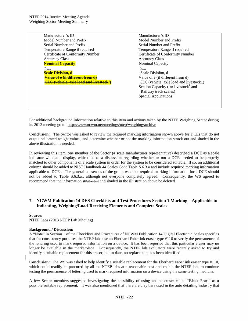
Marking Requirements for DCEs that Do Not Output a Calibrated Weight Values
Mark with: Mark with:
DIGITAL CONTROLLER
ELEMENT
Converts outputs from one or more
load cells to a calibrated digital
weight value ready for display
DIGITAL WEIGHT
INDICATING ELEMENT
Accepts input from Digital Controller
Element and displays calibrated weight
value
NTEP 2014 Interim Meeting Agenda
Weighing Sector Meeting Summary
NTEP - 22
Manufacturer’s ID Manufacturer’s ID
Model Number and Prefix Model Number and Prefix
Serial Number and Prefix Serial Number and Prefix
Temperature Range if required Temperature Range if required
Certificate of Conformity Number Certificate of Conformity Number
Accuracy Class Accuracy Class
Nominal Capacity Nominal Capacity
nmax nmax
Scale Division, d Scale Division, d
Value of e (if different from d) Value of e (if different from d)
CLC (vehicle, axle load and livestock1) CLC (vehicle, axle load and livestock1)
Section Capacity (for livestock1 and
Railway track scales)
Special Applications
For additional background information relative to this item and actions taken by the NTEP Weighing Sector during
its 2012 meeting go to: http://www.ncwm.net/meetings/ntep/weighing/archive
Conclusion: The Sector was asked to review the required marking information shown above for DCEs that do not
output calibrated weight values, and determine whether or not the marking information struck out and shaded in the
above illustration is needed.
In reviewing this item, one member of the Sector (a scale manufacturer representative) described a DCE as a scale
indicator without a display, which led to a discussion regarding whether or not a DCE needed to be properly
matched to other components of a scale system in order for the system to be considered suitable. If so, an additional
column should be added to NIST Handbook 44 Scales Code Table S.6.3.a and include required marking information
applicable to DCEs. The general consensus of the group was that required marking information for a DCE should
not be added to Table S.6.3.a., although not everyone completely agreed. Consequently, the WS agreed to
recommend that the information struck out and shaded in the illustration above be deleted.
NCWM Publication 14 DES Checklists and Test Procedures Section 1 Marking – Applicable to 7.
Indicating, Weighing/Load-Receiving Elements and Complete Scales
Source:
NTEP Labs (2013 NTEP Lab Meeting)
Background / Discussion:
A “Note” in Section 1 of the Checklists and Procedures of NCWM Publication 14 Digital Electronic Scales specifies
that for consistency purposes the NTEP labs use an Eberhard Faber ink eraser type #110 to verify the permanence of
the lettering used to mark required information on a device. It has been reported that this particular eraser may no
longer be available in the marketplace. Consequently, the NTEP lab evaluators were recently asked to try and
identify a suitable replacement for this eraser; but to date, no replacement has been identified.
Conclusion: The WS was asked to help identify a suitable replacement for the Eberhard Faber ink eraser type #110,
which could readily be procured by all the NTEP labs at a reasonable cost and enable the NTEP labs to continue
testing the permanence of lettering used to mark required information on a device using the same testing medium.
A few Sector members suggested investigating the possibility of using an ink eraser called “Black Pearl” as a
possible suitable replacement. It was also mentioned that there are clay bars used in the auto detailing industry that

NTEP 2014 Interim Meeting Agenda
Weighing Sector Meeting Summary
NTEP - 23
Load Cell
Specifications
Zero
Load
Minimum Dead Load
of Load Cell (Emin)
Maximum Measuring Range
Maximum Capacity
of Load Cell (Emax)
Safe Load
Limit (Elim)
Use or Test
might prove satisfactory. Mr. Truex agreed to look into the possibility of replacing the current eraser with one of the
products mentioned and to continue searching until a suitable replacement is found.
NCWM Publication 14 Load Cells - National Type Evaluation Program Terminology for Load 8.
Cell Parameters
Source: Mr. Steve Langford, Cardinal Scale (2013)
Background / Discussion: Mr. Steve Langford has discovered what he believes to be an editorial error in some of
the text included in Figure 1. Illustration of Load Cell Parameters on page LC-19 of NCWM Publication 14 Load
Cells. The illustration uses the term “Maximum Dead Load” in association with Dmax to identify the upper extreme
of the load cell measuring range. Mr. Langford believes the word “Dead” should be removed so that the term reads
“Maximum Load.” This change would align the text with footnote 7 of the illustration, the definition of Dmax in
NIST Handbook 44, and OIML R60 Section 2.3.6.
The WS was asked to review NCWM Publication 14 Load Cells Figure 1. Illustration of Load Cell Parameters and
determine whether or not the change suggested by Mr. Langford is appropriate and whether or not additional
changes to any of the text included in Figure 1. are needed. Figure 1. Illustration of Load Cell Parameters has been
copied from Publication 14 and pasted below with the change suggested by Mr. Langford shaded. Included for
reference are definitions of “Dmax” and “Dmin,” which were copied from NIST Handbook 44 and Section 2.3.6.,
copied from OIML R60.
Figure 1.
Illustration of Load Cell Parameters
Load Cell Measuring Range6
Maximum Dead Load
During Test or Use7 (Dmax)
6The limiting conditions for the measuring range for use or test are the minimum dead load and maximum capacity of the
load cell. 7Maximum load for National Type Evaluation Program test must be at least 90% of the maximum capacity of the load cell,
National Institute of Standards and Technology testing will not go beyond the maximum capacity of the load cell. If the
manufacturer test equipment limits the loads that may be applied, the manufacturer may test to a load in excess of the
maximum capacity of the load cell.
Appendix D – Definitions NIST Handbook 44:
Dmax (maximum load of the measuring range). – Largest value of a quantity (mass) which is applied to a load cell
during test or use. This value shall not be greater than Emax.[2.20]
(Added 2005)
Minimum Dead Load
During Test or Use (Dmin)

NTEP 2014 Interim Meeting Agenda
Weighing Sector Meeting Summary
NTEP - 24
Dmin (minimum load of the measuring range). – Smallest value of a quantity (mass) which is applied to a load cell
during test or use. This value shall not be less than Emin.[2.20]
(Added 2006)
OIML R 60 Metrological regulation for load cells:
2.3.6 Maximum load of the measuring range (Dmax) Largest value of a quantity (mass) which is applied to a
load cell during test or use. This value shall not be greater than Emax (see 2.3.5). For the limits on Dmax during
testing, see A.3.2.4.
Conclusion: The Sector agreed with Mr. Langford’s assertion that the word “Dead” should not appear in
association with Dmax and recommends that the word be removed from the illustration as suggested.
Identification of Certified Software 9.
Source: NTEP Software Sector (2013 Software Sector Meeting)
Background: This item originated as an attempt to answer the question “How does the field inspector know that
the software running in the device is the same software evaluated and approved by the lab?” In previous meetings it
was shown that the international community has addressed this issue (both WELMEC and OIML).
At the 2012 NTEP Software Sector Meeting, there was some discussion as to where the terminology regarding
inextricably linking the software version or revision to the software itself belonged. The Software Sector
recommended adding the following to NCWM Publication 14 and forward to NTEP Weighing, Measuring, and
Grain Analyzer Sectors for feedback:
Identification of Certified Software:
Note: Manufacturers may choose to separate metrologically significant software from non-metrologically
significant software. Separation would allow the revision of the non-metrological portion without the need for
further evaluation. In addition, non-metrologically significant software may be updated on devices without
breaking a seal, if so designed. Separation of software requires that all software modules (programs,
subroutines, objects, etc.) that perform metrologically significant functions or that contain metrologically
significant data domains form the metrologically significant software part of a measuring instrument (device or
sub-assembly). If the separation of the software is not possible or needed, then the software is metrologically
significant as a whole. The conformity requirement applies to all parts and parts shall be marked according to
Section G-S-X.X.
The manufacturer must describe and possibly demonstrate how the version or revision identifier is directly and
inseparably linked to the metrologically significant software. Where the version revision identifier is comprised
of more than one part, the manufacturer shall describe which portion represents the metrological significant
software and which does not.
Conclusion: Members of the Weighing Sector reviewed the two paragraphs shown above for which the
Software Sector requested feedback and after agreeing that the last sentence of the first paragraph should be
deleted, agreed to recommend that both paragraphs (minus the last sentence of the first paragraph) be added to
the following Sections of NCWM Publication 14:
DES Section 3;
ECRS Section 5.11;
ABWS Section 17.5.; and

NTEP 2014 Interim Meeting Agenda
Weighing Sector Meeting Summary
NTEP - 25
AWS Section 1.2.
The following text, less the struck out sentence shown, is recommended by the Sector for insertion into the
Sections of Publication 14 identified above:
Identification of Certified Software:
Note: Manufacturers may choose to separate metrologically significant software from non-metrologically
significant software. Separation would allow the revision of the non-metrological portion without the
need for further evaluation. In addition, non-metrologically significant software may be updated on
devices without breaking a seal, if so designed. Separation of software requires that all software modules
(programs, subroutines, objects, etc.) that perform metrologically significant functions or that contain
metrologically significant data domains form the metrologically significant software part of a measuring
instrument (device or sub-assembly). If the separation of the software is not possible or needed, then the
software is metrologically significant as a whole. The conformity requirement applies to all parts and
parts shall be marked according to Section G-S-X.X.
The manufacturer must describe and possibly demonstrate how the version or revision identifier is
directly and inseparably linked to the metrologically significant software. Where the version revision
identifier is comprised of more than one part, the manufacturer shall describe which portion represents
the metrological significant software and which does not.
Software Protection / Security 10.
Source:
NTEP Software Sector (2013 Software Sector Meeting)
Background
The NTEP Software Sector agreed that NIST Handbook 44 already has audit trail and physical seal, but these may
need to be enhanced.
From the WELMEC Document:
Protection against accidental or unintentional changes
Metrologically significant software and measurement data shall be protected against accidental or unintentional
changes.
Specifying Notes:
Possible reasons for accidental changes and faults are: unpredictable physical influences, effects caused by user
functions and residual defects of the software even though state of the art of development techniques have been
applied.
This requirement includes consideration of:
a) Physical influences: Stored measurement data shall be protected against corruption or deletion when a
fault occurs or, alternatively, the fault shall be detectable.
b) User functions: Confirmation shall be demanded before deleting or changing data.
c) Software defects: Appropriate measures shall be taken to protect data from unintentional changes that
could occur through incorrect program design or programming errors, e.g. plausibility checks.
Required Documentation:

NTEP 2014 Interim Meeting Agenda
Weighing Sector Meeting Summary
NTEP - 26
The documentation should show the measures that have been taken to protect the software and data against
unintentional changes.
Example of an Acceptable Solution:
The accidental modification of software and measurement data may be checked by calculating a checksum
over the relevant parts, comparing it with the nominal value and stopping if anything has been modified.
Measurement data are not deleted without prior authorization, e.g. a dialogue statement or window asking
for confirmation of deletion.
For fault detection see also Extension I.
The Software Sector continued to develop a proposed checklist for NCWM Publication 14. The numbering will still
need to be added. This is based roughly on R 76 – 2 checklist and discussions beginning as early as the October
2007 NTEP Software Sector Meeting. The information requested by this checklist is currently voluntary, however,
it is recommended that applicants comply with these requests or provide specific information as to why they may
not be able to comply. Based on this information, the checklist may be amended to better fit with NTEP's need for
information and the applicant's ability to comply.
The California, Maryland, and Ohio laboratories agreed to use this check list on one of the next devices they have in
the lab and report back to the Sector on what the problems may be. In February 2011, the North Carolina laboratory
was also given a copy of the check list to try.
1. Devices with Embedded Software TYPE P (aka built-for-purpose)
1.1. Declaration of the manufacturer that the software is used in a fixed hardware
and software environment. AND
Yes No N/A
1.2. Cannot be modified or uploaded by any means after securing/verification. Yes No N/A
Note: It is acceptable to break the "seal" and load new software, audit trail is also
a sufficient seal.
1.3 The software documentation contains:
1.3.1. Description of all functions, designating those that are considered
metrologically significant.
Yes No N/A
1.3.2. Description of the securing means (evidence of an intervention). Yes No N/A
1.3.3. Software Identification, including version / revision Yes No N/A
1.3.4. Description how to check the actual software identification. Yes No N/A
1.4. The software identification is:
1.4.1. Clearly assigned to the metrologically significant software and functions. Yes No N/A
1.4.2. Description how to check the actual software identification. Yes No N/A
1.4.3. Provided by the device as documented. Yes No N/A
1.4.4. Directly linked to the software itself. Yes No N/A
2. Personal Computers, Instruments with PC Components, and Other Instruments, Devices, Modules, and
Elements with Programmable or Loadable Metrologically Significant Software TYPE U (aka not built-
for-purpose)
2.1. The metrologically significant software is:
2.1.1. Documented with all relevant (see below for list of documents)
information.
Yes No N/A
2.1.2. Protected against accidental or intentional changes. Yes No N/A

NTEP 2014 Interim Meeting Agenda
Weighing Sector Meeting Summary
NTEP - 27
2.2. Evidence of intervention (such as, changes, uploads, circumvention) is
available until the next verification / inspection (e.g., physical seal, Checksum,
Cyclical Redundancy Check (CRC), audit trail, etc. means of security).
Yes No N/A
3. Software with Closed Shell (no access to the operating system and/or programs possible for the user)
3.1. Check whether there is a complete set of commands (e.g., function keys or
commands via external interfaces) supplied and accompanied by short
descriptions.
Yes No N/A
3.2. Check whether the manufacturer has submitted a written declaration of the
completeness of the set of commands.
Yes No N/A
4. Operating System and / or Program(s) Accessible for the User
4.1 Check whether a checksum or equivalent signature is generated over the
machine code of the metrologically significant software (program module(s)
subject to legal control Weights and Measures jurisdiction and type-specific
parameters).
Yes No N/A
4.2 Check whether the metrologically significant software will detect and act upon
any unauthorized alteration of the metrologically significant software using
simple software tools (e.g., text editor).
Yes No N/A
5. Software Interface(s)
5.1 Verify the manufacturer has documented:
5.1.1. The program modules of the metrologically significant software are
defined and separated.
Yes No N/A
5.1.2. The protective software interface itself is part of the metrologically
significant software.
Yes No N/A
5.1.3. The functions of the metrologically significant software that can be
accessed via the protective software interface.
Yes No N/A
5.1.4. The parameters that may be exchanged via the protective software
interface are defined.
Yes No N/A
5.1.5. The description of the functions and parameters are conclusive and
complete.
Yes No N/A
5.1.6. There are software interface instructions for the third party (external)
application programmer.
Yes No N/A
The Maryland laboratory had particular questions regarding 3.1 and 5.1. The information for 3.1 could be acquired
from an operator’s manual, a training video, or in-person training. The items in 5.1 were confusing to the
evaluators. The terminology is familiar to software developers, but not necessarily others. It was indicated that
manufacturers were typically quick to return the filled out questionnaire, but he didn’t know how his laboratory was
supposed to verify that it was true. Generally, the laboratories wouldn’t be expected to verify things to that level.
For example, if the manufacturer states that a checksum is used to ensure integrity, the laboratories wouldn’t be
expected to evaluate the algorithm used.
The intent was to see whether the manufacturer had at least considered these issues, not for evaluators to become
software engineers. Perhaps a glossary or descriptive paragraphs might be added to assist the evaluators for if the
manufacturer has questions for the evaluators.
OIML makes use of supplementary documents to explain the checklist they use. Below are links:

NTEP 2014 Interim Meeting Agenda
Weighing Sector Meeting Summary
NTEP - 28
http://www.oiml.org/publications/D/D031-e08.pdf
http://www.welmec.org/latest/guides/72.html
http://www.welmec.org/fileadmin/user_files/publications/2-3.pdf
WELMEC document 2.3 is the original source for our checklist, but it’s been significantly revised and simplified.
Mr. Payne, Maryland Department of Agriculture, is going to review the other documents and come up with some
suggestions for the checklist. Mr. Roach, California Division of Measurement Standards, is going to begin using
the checklist. The international viewpoint is that any device running an operating system is considered to be Type
U. Mr. Roach mentioned that they’re having lots of problems with “skimmers” stealing PIN’s. Is there some way
they can detect this?
Mr. Lewis, Rice Lake Weighing Systems, Inc., mentioned that he liked Measurement Canada’s website. When
answering similar questions, different pages would appear, based on answers to those questions:
http://www.ic.gc.ca/eic/site/mc-mc.nsf/eng/lm00573.html
At the 2011 NTEP Software Sector Meeting, the laboratories were polled to obtain any feedback on the use of the
checklist. Maryland attempted to use this checklist a few times. They had some difficulty obtaining answers from
the manufacturers because the individual(s) interacting with the Maryland evaluator didn’t always have the required
information on hand. More experience in using the checklist will help determine what needs to be revised.
It was suggested that the checklist could be sent to manufacturers for their feedback as well, with the stipulation that
it be a completely voluntary exercise and purely informational at this point. The laboratories will coordinate with
willing manufacturers to obtain feedback.
Work is ongoing on this item with the intent that it eventually will be incorporated as a checklist in NCWM
Publication 14; again the laboratories are requested to try utilizing this checklist for any evaluations on software-
based electronic devices.
The checklist has been reviewed with an eye to making its terminology clearer to laboratories. Some examples and
clarifications have been added as shown in the discussion section of this item. The revised checklist will be
distributed to the laboratories for additional review. Maryland and California laboratories agreed to use the checklist
on a trial basis.
Discussion:
Over the past year, attempts to use the current checklist did not meet with many difficulties. The checklists were
given to the manufacturers to fill out, and that seemed to work rather well. Minor modifications (in red above) were
made to clarify certain confusing areas or eliminate redundancy.
Conclusion:
The WS was asked to consider whether or not it is appropriate to add the proposed software checklist to NCWM
Publication 14, and if so, to identify which of the checklists within Publication 14 Weighing Devices it is be
included, e.g., DES, AWS, etc.
Feedback to the Software Sector. The WS reviewed the checklist and is opposed to adding it to any of the
Weighing Device checklists within NCWM Publication 14 for the following reasons:
nonretroactive application: i.e., a concern was raised concerning applying the checklist to existing
equipment with software.
metrological and nonmetrological software issue: i.e., Subsection 1.2. of the checklist implies that you
cannot load any software without breaking a seal.
The checklist is not supported by NIST Handbook 44.
The meaning of some terms included in the checklist is not clear, e.g., “fixed hardware,” “software
environment.”

NTEP 2014 Interim Meeting Agenda
Weighing Sector Meeting Summary
NTEP - 29
Software Maintenance and Reconfiguration 11.
Source:
NTEP Software Sector (2013 Software Sector Meeting)
Background
After the software is completed, what do the manufacturers use to secure their software? The following items were
reviewed by the NTEP Software Sector. Note that agenda Item 3 also contains information on Verified and Traced
updates and Software Log.
1. Verify that the update process is documented (OK)
2. For traced updates, installed Software is authenticated and checked for integrity
Technical means shall be employed to guarantee the authenticity of the loaded software (i.e., that it originates
from the owner of the type approval certificate). This can be accomplished (e.g., by cryptographic means like
signing). The signature is checked during loading. If the loaded software fails this test, the instrument shall
discard it and either use the previous version of the software or become inoperative.
Technical means shall be employed to guarantee the integrity of the loaded software, i.e., that it has not been
inadmissibly changed before loading. This can be accomplished, for example, by adding a checksum or hash
code of the loaded software and verifying it during the loading procedure. If the loaded software fails this test,
the instrument shall discard it and either use the previous version of the software or become inoperative.
Examples are not limiting or exclusive.
3. Verify that the sealing requirements are met
The Software Sector asked “What sealing requirements are we talking about?”
This item is only addressing the software update. It can be either verified or traced. It is possible that there
are two different security means, one for protecting software updates (software log) and one for protecting the
other metrological parameters (Category I, II, or III method of sealing). Some examples provided by the Sector
members include but are not limited to:
Physical Seal, software log
Category III method of sealing can contain both means of security
4. Verify that if the upgrade process fails, the device is inoperable or the original software is restored
The question before the group is, Can this be made mandatory?
The manufacturer shall ensure by appropriate technical means (e.g. an audit trail) that traced updates of
metrologically significant software are adequately traceable within the instrument for subsequent verification
and surveillance or inspection. This requirement enables inspection authorities, which are responsible for the
metrological surveillance of legally controlled instruments, to back-trace traced updates of metrologically
significant software over an adequate period of time (that depends on national legislation). The statement in
italics will need to be reworded to comply with US weights and measures requirements.
The Software Sector agreed that the two definitions below for Verified update and Traced update were acceptable.
Verified Update
A verified update is the process of installing new software where the security is broken and the device must be
re-verified. Checking for authenticity and integrity is the responsibility of the owner/user.
Traced Update
A traced update is the process of installing new software where the software is automatically checked for
authenticity and integrity, and the update is recorded in a software update log or audit trail.

NTEP 2014 Interim Meeting Agenda
Weighing Sector Meeting Summary
NTEP - 30
Note: It’s possible that the Philosophy of Sealing section of NCWM Publication 14 may already address the above
IF the definitions of Verified and Traced Updates (and the statement below) were to be added. The contrary
argument was that it may be better to be explicit).
Use of a Category 3 audit trail is required for a Traced Update. A log entry representing a traced
software update shall include the software identification of the newly installed version.
The Sector recommended consolidating the definitions with the above statement thus:
Verified Update
A verified update is the process of installing new software where the security is broken and the device must be
re-verified. Checking for authenticity and integrity is the responsibility of the owner/user.
Traced Update
A traced update is the process of installing new software where the software is automatically checked for
authenticity and integrity, and the update is recorded in a software update log or Category 3 audit trail. The
audit trail entry shall include the software identification of the newly installed version.
In 2012, the Sector recommended that as a first step, the following be added to NCWM Publication 14:
The updating of metrologically significant software, including software that checks the authenticity
and integrity of the updates, shall be considered a sealable event.
Mr. Truex, NTEP Administrator, indicated that, in his opinion, the above sentence is unnecessary since it’s self-
evident. It was agreed by the group however to ask the other sectors for feedback on the value of this addition.
Though the Software Sector is currently considering only the single sentence be incorporated into NCWM
Publication 14 for the time being, ultimately, the Sector may wish to advance the remaining language of the original
item submission.
Discussion: The Software Sector had no information indicating that the other Sectors had yet been approached for feedback on
the value of the addition of the proposed sentence.
Recommendation:
The Software Sector is requesting each of the NTEP Sectors review and provide feedback on the following draft
language it developed for consideration of adding it to NCWM Publication 14:
The updating of metrologically significant software, including software that checks the authenticity
and integrity of the updates, shall be considered a sealable event.
The Software Sector is also requesting feedback from the NTEP Sectors regarding whether or not additional
language is needed in NCWM Publication 14 to make clear that an existing audit trail should be protected during a
software update. In the background information provided for this item, it was noted that the Software Sector noted
that this does already seem to be addressed in the Requirements for Metrological Audit Trails in Publication 14.
NIST Technical Advisor’s note: NCWM Publication 14 DES Appendix B item 5 b. on page DES – 156 of General
Requirements for Metrological Audit Trails addresses the protection of audit trail data as follows and may be why
the Software Sector has indicated that this issue already seems to be addressed in Publication 14:
5.1.6.1. The audit trail data shall be:
a. Stored in non-volatile memory and shall be retained for at least 30 days if power is removed from the
device. AND
b. Protected from unauthorized erasure, substitution, or modification.

NTEP 2014 Interim Meeting Agenda
Weighing Sector Meeting Summary
NTEP - 31
This same provision also appears in Publication 14 AWS Appendix B.
Conclusion: The WS is opposed to adding the proposed sentence into NCWM Publication 14 at this time for the
following reasons:
If this statement were added into Publication 14, it would change the existing sealing requirements for
devices with category 1, 2, and 3 methods of sealing. Category 1, 2, and 3 sealing does not currently
require identification of software changes to event counters or event loggers. This would require a change
to NIST Handbook 44.
It’s not clear that the requirement for authenticity and integrity of the updates is limited to only
metrological significant software.
The WS currently believes that Publication 14 is not clear on whether or not an existing audit trail should be
protected during a software update. This issue will need to be addressed as software requirements are added to
NIST Handbook 44.
ATTACHMENTS
2014 Weighing Sector Meeting: NTEP Weighing Sector / August 26-27, 2014 / Site TBD [CA, Chicago, Atlanta,
Denver]
Appendix A - 2013 NTEP Weighing Sector Attendees (to be included in the Sector report)