digital weighing indicator si 200 - sewha cnm · 2014-10-28 · wall mounting type digital weighing...
TRANSCRIPT
Digital Weighing Indicator
SI 200 Instruction Manual
Ver. 1.18
WALL Mounting Type DIGITAL WEIGHING INDICATOR SI 200
2
CONTENTS
1. Before Installation ----------------- 3 Page
2. Introduction ----------------- 4 Page
3. Installation ----------------- 6 Page
4. Set-up ----------------- 10 Page
4-1. Calibration ----------------- 10 Page
4-2. Test Weight Calibration ----------------- 10 Page
4-3. Simulating Calibration ----------------- 13 Page
4-4. TEST mode ----------------- 16 Page
4-5. F-FUNCTION Setting ----------------- 18 Page
4-6. F-FUNCTION List ----------------- 20 Page
4-7. F-FUNCTION explanation ----------------- 21 Page
5. Interface ----------------- 24 Page
5-1. RS-232C ----------------- 24 Page
5-2. RS-485 ----------------- 24 Page
5-3 Data format ----------------- 25 Page
5-4.Command mode ----------------- 26 Page
5-5.Command mode ex ----------------- 30 Page
5-6.Print Interface ----------------- 32 Page
6. Error & Treatment ----------------- 35 Page
Warrantee Certificate ----------------- 37Page

WALL Mounting Type DIGITAL WEIGHING INDICATOR SI 200
3
1. BEFORE INSTALLATION
1-1. Caution / Warning Marks
Warning
This mark warns the possibility to arrive death or serious injury
in case of wrongly used.
Cautions
This mark cautions the possibility to arrive serious human body
injury or product lose in case of wrongly used.
1-2. Copy Rights
① All Right and Authority for this Manual is belonged to SEWHA CNM CO., LTD.
② Any kinds of copy or distribution without permission of SEWHA CNM CO., LTD. will be
prohibited.
③ This manual may be changed as the version is upgraded, without previous notice.
You can get the information at our website.
1-3. Inquiries
If you have any kinds of inquiries for this model, please contact your local agent or
Head Office.
Head Office : SEWHA CNM CO., LTD.
Website : http://www.sewhacnm.co.kr
Email : [email protected]
!

WALL Mounting Type DIGITAL WEIGHING INDICATOR SI 200
4
2. INTRODUCTION
2-1. Features
- As a Wall / Rail Mounting type Indicator, it is convenient to set them at the narrow
site because of the small size. Especially at the control panel it is very easy and
gives you enough spaces.
- Polycarbonate film panel, strong for dust and water.
- RS-232/485 is standard for more serial interface.(Selectable)
- Data Back-up function for case of that when the power suddenly off.
2-2. Specification
Content Specification
Performance
External Resolution 1/20,000
Internal Resolution 1/2,097,152 (±1,048,576)
Input Sensitivity Min 0.1µV/V
Max. Signal Input Voltage 3.00mV/V
Load cell Excitation DC +5V
A/D Conversion Method Sigma-Delta
Decimal Point 0, 0.0, 0.00, 0.000
Drift Offset 10PPM/
Span 10PPM/
Linearity 0.001% of Full Scale
Analogue Sampling(sec) 60times / sec
Environment
Operating Temperature Range -10 ~ +40 [14 ~ 104]
Operation Humidity Range 40% ~ 85% RH, Non-condensing
Function
Test Weight Calibration Mode / Simulation Calibration Mode (Without Test Weight)
Display 6 digit, 7.6mm(0.3inch)Yellow green FND
4ea standard Key
Comm. Serial Interface
(RS-232C/RS-485 selectable)
Data Transference Command Mode
Serial Printer Mode
Power Input Power DC 9 ~ 12VPower Consumption MAX 8W
Size 49mm(W)ⅹ96mm(H)ⅹ41mm(D) -body , Weight : 140g

WALL Mounting Type DIGITAL WEIGHING INDICATOR SI 200
5
2-3. Application
2-4. SEWHACNM ‘s other indicators
SI 4000series
SI 4000 SI 4010/R SI 4100 SI 4200
Simple
type
Simple
/Controller
Universal
Controller Counter
SI 4300 SI 4400 SI 4410 SI 4500
SI 4630Simple/
Wall mounting
Checker Packer Filler Accumulation
Controller
SI 480 SI 580 SI 480/580 DIN Size
Simple
Din size
Din size
Controller
WALL Mounting Type DIGITAL WEIGHING INDICATOR SI 200
6
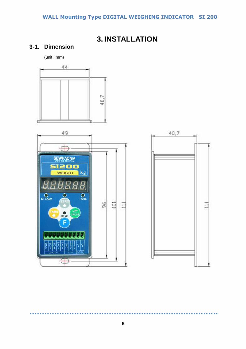
3. INSTALLATION 3-1. Dimension
(unit : mm)

WALL Mounting Type DIGITAL WEIGHING INDICATOR SI 200
7
3-2. Front Panel 3-2-1. Image
3-2-1. State Lamp
STEADY When the weight is “STEADY”, Lamp is ON.
ZERO When the current weight is ”ZERO”, Lamp is ON.
TARE “TARE” function is set, Lamp is ON.
RTxD RxD–Red, TxD-Green [F-39 setting]
3-2-2. Connectors
LOAD CELL Serial Interface POWER
1 2 3 4 5 6 7 8 9 10
SHLD SIG
- SIG
+ EXC
- EXC
+ GND
RS485 RS232C RS485 RS232C
GND DC
+12V RTx -
TxD RTx
+ RxD
Please check the Comm. and other specification in the label, attached
on the cover plate first, and make connection according to that
information.
State lamp
4ea Key pad
Load cell/Serial/Power
connector
Calibration Switch
Comm. Lampp
RS232C/485 Side switch
Up : RS232C(default) Down: RS485(F39-01)
Weight display

WALL Mounting Type DIGITAL WEIGHING INDICATOR SI 200
8
3-2-3. Key Operation
- Make Weight value as Zero.
- Refer to F-07,F-08
- Set the TARE Function .(F09 setting)
- Refer to F-14
- Press this key 4times, within 2secs, enter “SET-UP” mode.
-Refer to F14, F15
- Under “TARE” setting, you can select weight display mode.
- First input, Gross Weight will be displayed, second input, Net weight
will be displayed.
※ This key will be activated only under “TARE” set.
In this caseG g 580 set G(gross weight) will display in front of
the value.
-TARE RESET key (refer to F14)
HOT Key (with F key)
- TARE RESET (Refer to F 15)
- PRINT (Refer to F15)
If the Printer is installed,
You can print out the “Grand-total data”.
(GRAND-total data can be checked though Print output).
Max. accumulated weighing count : 999,999 times
Over 999,999times return to “0” time Max. accumulated weight display : 999,999,999
Over 999,999,999 return to “0”
!
WALL Mounting Type DIGITAL WEIGHING INDICATOR SI 200
9
!
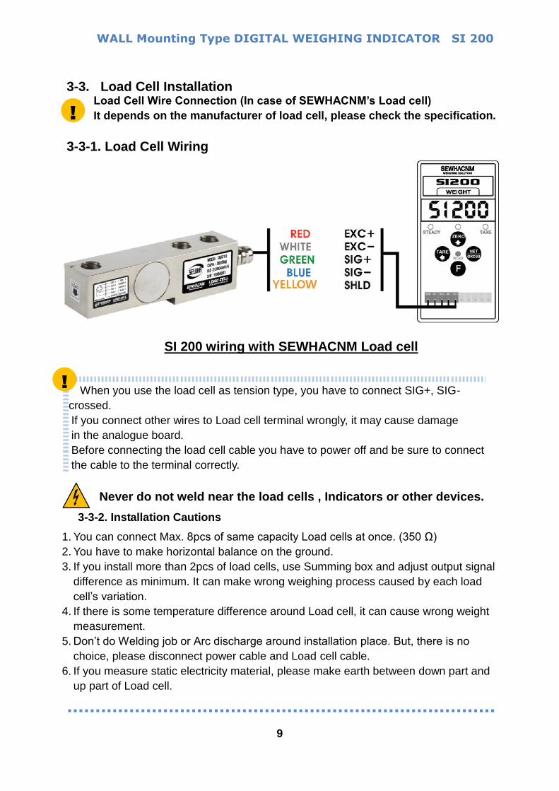
3-3. Load Cell Installation Load Cell Wire Connection (In case of SEWHACNM’s Load cell)
It depends on the manufacturer of load cell, please check the specification.
3-3-1. Load Cell Wiring
When you use the load cell as tension type, you have to connect SIG+, SIG-
crossed.
If you connect other wires to Load cell terminal wrongly, it may cause damage
in the analogue board.
Before connecting the load cell cable you have to power off and be sure to connect
the cable to the terminal correctly.
Never do not weld near the load cells , Indicators or other devices.
3-3-2. Installation Cautions
1. You can connect Max. 8pcs of same capacity Load cells at once. (350 Ω)
2. You have to make horizontal balance on the ground.
3. If you install more than 2pcs of load cells, use Summing box and adjust output signal
difference as minimum. It can make wrong weighing process caused by each load
cell’s variation.
4. If there is some temperature difference around Load cell, it can cause wrong weight
measurement.
5. Don’t do Welding job or Arc discharge around installation place. But, there is no
choice, please disconnect power cable and Load cell cable.
6. If you measure static electricity material, please make earth between down part and
up part of Load cell.
SI 200 wiring with SEWHACNM Load cell
!
WALL Mounting Type DIGITAL WEIGHING INDICATOR SI 200
10
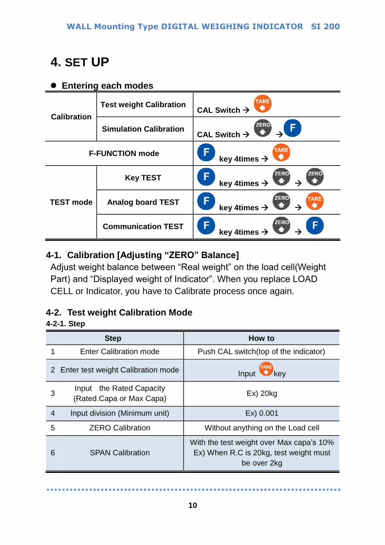
4. SET UP
Entering each modes
Calibration
Test weight Calibration CAL Switch
Simulation Calibration CAL Switch
F-FUNCTION mode key 4times
TEST mode
Key TEST key 4times
Analog board TEST key 4times
Communication TEST key 4times
4-1. Calibration [Adjusting “ZERO” Balance]
Adjust weight balance between “Real weight” on the load cell(Weight
Part) and “Displayed weight of Indicator”. When you replace LOAD
CELL or Indicator, you have to Calibrate process once again.
4-2. Test weight Calibration Mode
4-2-1. Step
Step How to
1 Enter Calibration mode Push CAL switch(top of the indicator)
2 Enter test weight Calibration mode Input key
3 Input the Rated Capacity
(Rated.Capa or Max Capa) Ex) 20kg
4 Input division (Minimum unit) Ex) 0.001
5 ZERO Calibration Without anything on the Load cell
6 SPAN Calibration
With the test weight over Max capa’s 10%
Ex) When R.C is 20kg, test weight must
be over 2kg
WALL Mounting Type DIGITAL WEIGHING INDICATOR SI 200
11
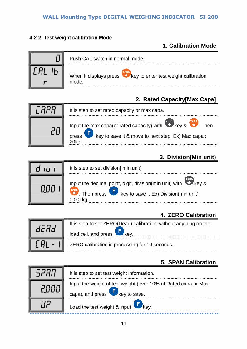
4-2-2. Test weight calibration Mode
1. Calibration Mode
0 Push CAL switch in normal mode.
Cal1br
When it displays press key to enter test weight calibration mode.
2. Rated Capacity[Max Capa]
Capa It is step to set rated capacity or max capa.
20
Input the max capa(or rated capacity) with key & . Then
press key to save it & move to next step. Ex) Max capa : 20kg
3. Division[Min unit)
diui It is step to set division[ min unit].
0.001
Input the decimal point, digit, division(min unit) with key &
. Then press key to save .. Ex) Division(min unit) 0.001kg.
4. ZERO Calibration
dead It is step to set ZERO(Dead) calibration, without anything on the
load cell. and press key.
Cal-1 ZERO calibration is processing for 10 seconds.
5. SPAN Calibration
5paN It is step to set test weight information.
2.000 Input the weight of test weight (over 10% of Rated capa or Max
capa), and press key to save.
Up Load the test weight & input key.

WALL Mounting Type DIGITAL WEIGHING INDICATOR SI 200
12
Cal-1 SPAN Calibration is processing for about 10 seconds.
0.42607
After calculation, when span value shows input key to save.
end All of the calibration step is over.
Pressing key means calcel, pressing key means saving or going next.
4-2-3. Test weight calibration cause & treatment
err-1 It shows in case of .
Ex) When Rated capa[Max capa] is 20,000kg , division[Min unit]
cannot be under 1kg
err-4 It shows when the Test weight > Rated capa[Max capa]
Then please re-input right value again.
The more heavy test weight makes the more accurate
measurement.
err-5 It shows when the Test weight < 10% of Rated capa[Max capa]
Then Please re-input right value agian.
err-6 Amp. Gain is too big
Sig+/- wiring is connected wrongly.
The test weight is not loaded.
err-7 Amp. Gain is too small
Sig+/- wiring is connected wrongly.
The test weight is not loaded.
err-a there is vibration on the load cell or load cell wire, the indicator
cannot calculate
calibration anymore.
WALL Mounting Type DIGITAL WEIGHING INDICATOR SI 200
13
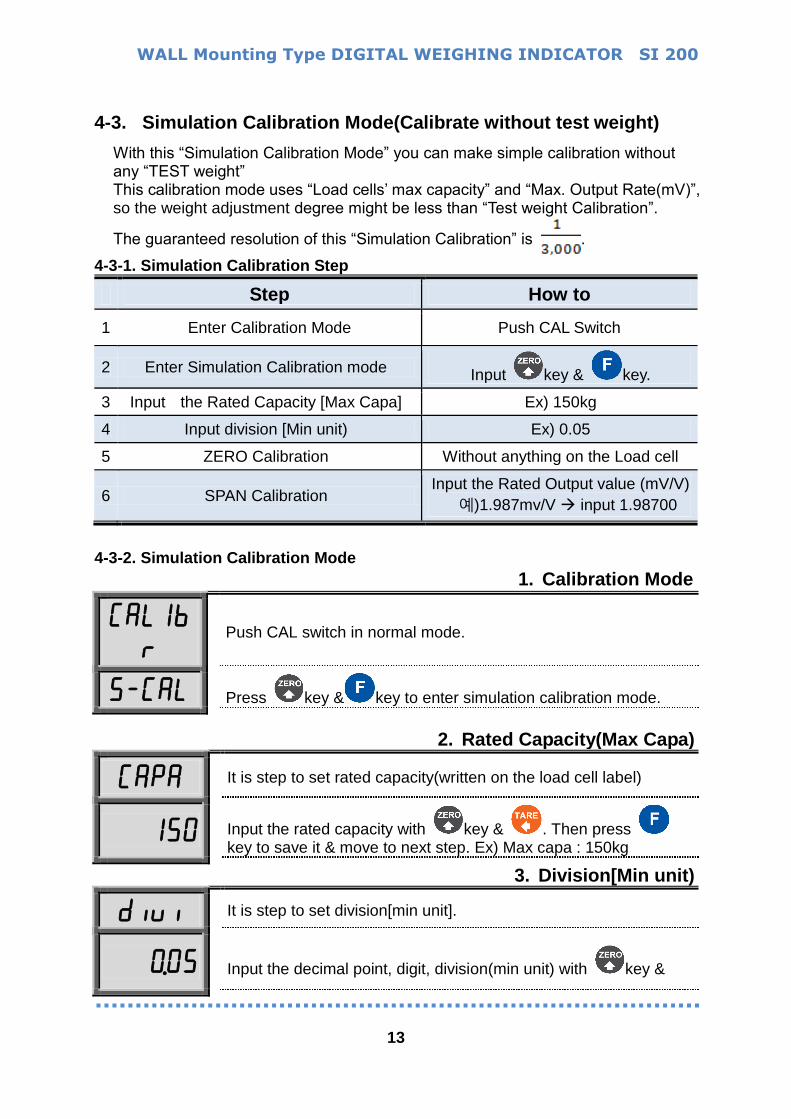
4-3. Simulation Calibration Mode(Calibrate without test weight)
With this “Simulation Calibration Mode” you can make simple calibration without any “TEST weight” This calibration mode uses “Load cells’ max capacity” and “Max. Output Rate(mV)”, so the weight adjustment degree might be less than “Test weight Calibration”.
The guaranteed resolution of this “Simulation Calibration” is .
4-3-1. Simulation Calibration Step
Step How to
1 Enter Calibration Mode Push CAL Switch
2 Enter Simulation Calibration mode Input key & key.
3 Input the Rated Capacity [Max Capa] Ex) 150kg
4 Input division [Min unit) Ex) 0.05
5 ZERO Calibration Without anything on the Load cell
6 SPAN Calibration Input the Rated Output value (mV/V)
예)1.987mv/V input 1.98700
4-3-2. Simulation Calibration Mode
1. Calibration Mode
Cal1br
Push CAL switch in normal mode.
5-Cal Press key & key to enter simulation calibration mode.
2. Rated Capacity(Max Capa)
Capa It is step to set rated capacity(written on the load cell label)
150
Input the rated capacity with key & . Then press key to save it & move to next step. Ex) Max capa : 150kg
3. Division[Min unit)
diui It is step to set division[min unit].
0.05
Input the decimal point, digit, division(min unit) with key &
WALL Mounting Type DIGITAL WEIGHING INDICATOR SI 200
14
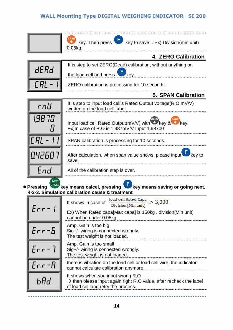
key. Then press key to save .. Ex) Division(min unit) 0.05kg.
4. ZERO Calibration
dead It is step to set ZERO(Dead) calibration, without anything on
the load cell and press key.
Cal-1 ZERO calibration is processing for 10 seconds.
5. SPAN Calibration
rnU It is step to input load cell’s Rated Output voltage(R.O mV/V) written on the load cell label.
1.98700
Input load cell Rated Output(mV/V) with key & key. Ex)In case of R.O is 1.987mV/V Input 1.98700
Cal-11 SPAN calibration is processing for 10 seconds.
0.42607
After calculation, when span value shows, please input key to save.
end All of the calibration step is over.
Pressing key means calcel, pressing key means saving or going next. 4-2-3. Simulation calibration cause & treatment
err-1 It shows in case of .
Ex) When Rated capa[Max capa] is 150kg , division[Min unit] cannot be under 0.05kg.
err-6 Amp. Gain is too big
Sig+/- wiring is connected wrongly. The test weight is not loaded.
err-7 Amp. Gain is too small
Sig+/- wiring is connected wrongly. The test weight is not loaded.
err-a there is vibration on the load cell or load cell wire, the indicator cannot calculate calibration anymore.
bad It shows when you input wrong R.O then please input again right R.O value, after recheck the label of load cell and retry the process.
WALL Mounting Type DIGITAL WEIGHING INDICATOR SI 200
15
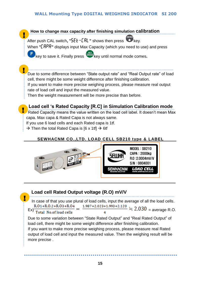
How to change max capacity after finishing simulation calibration
After push CAL switch, "5et-Cal" shows then press key.
When "Capa" displays input Max Capacity (which you need to use) and press
key to save it. Finally press key until normal mode comes.
Due to some difference between “State output rate” and “Real Output rate” of load
cell, there might be some weight difference after finishing calibration.
If you want to make more precise weighing process, please measure real output
rate of load cell and input the measured value.
Then the weight measurement will be more precise than before.
Load cell ‘s Rated Capacity [R.C] in Simulation Calibration mode
Rated Capacity means the value written on the load cell label. It doesn’t mean Max
capa. Max capa & Rated Capa is not always same.
If you use 6 load cells and each Rated capa is 1tf.
Then the total Rated Capa is [6 x 1tf] 6tf
SEWHACNM CO.,LTD. LOAD CELL SB210 type & LABEL
Load cell Rated Output voltage (R.O) mV/V
In case of that you use plural of load cells, input the average of all the load cells.
Ex) = average R.O.
Due to some variation between “State Rated Output” and “Real Rated Output” of
load cell, there might be some weight difference after finishing calibration.
If you want to make more precise weighing process, please measure real Rated
output of load cell and input the measured value. Then the weighing result will be
more precise .
!
!
!
!
WALL Mounting Type DIGITAL WEIGHING INDICATOR SI 200
16
!
!
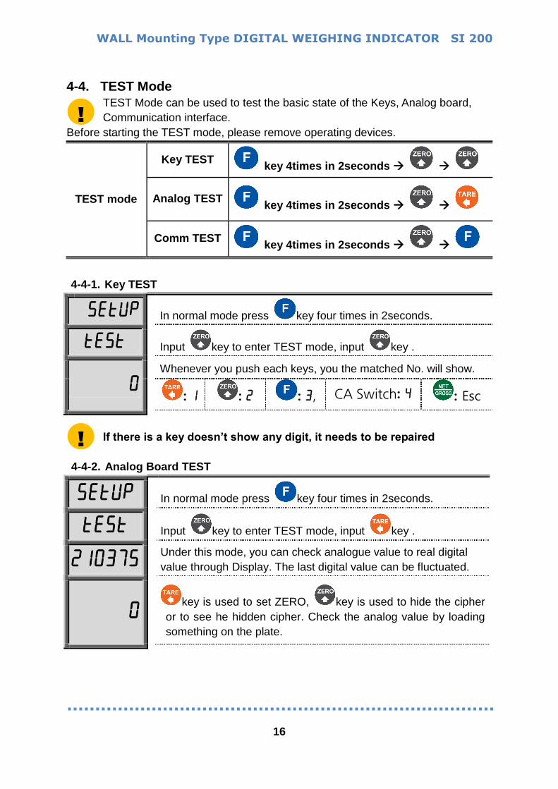
4-4. TEST Mode
TEST Mode can be used to test the basic state of the Keys, Analog board,
Communication interface.
Before starting the TEST mode, please remove operating devices.
TEST mode
Key TEST key 4times in 2seconds
Analog TEST key 4times in 2seconds
Comm TEST key 4times in 2seconds
4-4-1. Key TEST
5etUp In normal mode press key four times in 2seconds.
te5t Input key to enter TEST mode, input key .
0 Whenever you push each keys, you the matched No. will show.
: 1 : 2 : 3, CA Switch: 4 : Esc
If there is a key doesn’t show any digit, it needs to be repaired
4-4-2. Analog Board TEST
5etUp In normal mode press key four times in 2seconds.
te5t Input key to enter TEST mode, input key .
210375 Under this mode, you can check analogue value to real digital
value through Display. The last digital value can be fluctuated.
0
key is used to set ZERO, key is used to hide the cipher
or to see he hidden cipher. Check the analog value by loading
something on the plate.
WALL Mounting Type DIGITAL WEIGHING INDICATOR SI 200
17
!
If there is no change although pressing keys or loading some force on/in
weighing part , it may something wrong with load cell, cable, connector or A/D
board
This Analog test mode can be used to keep the balance at the wide platform.
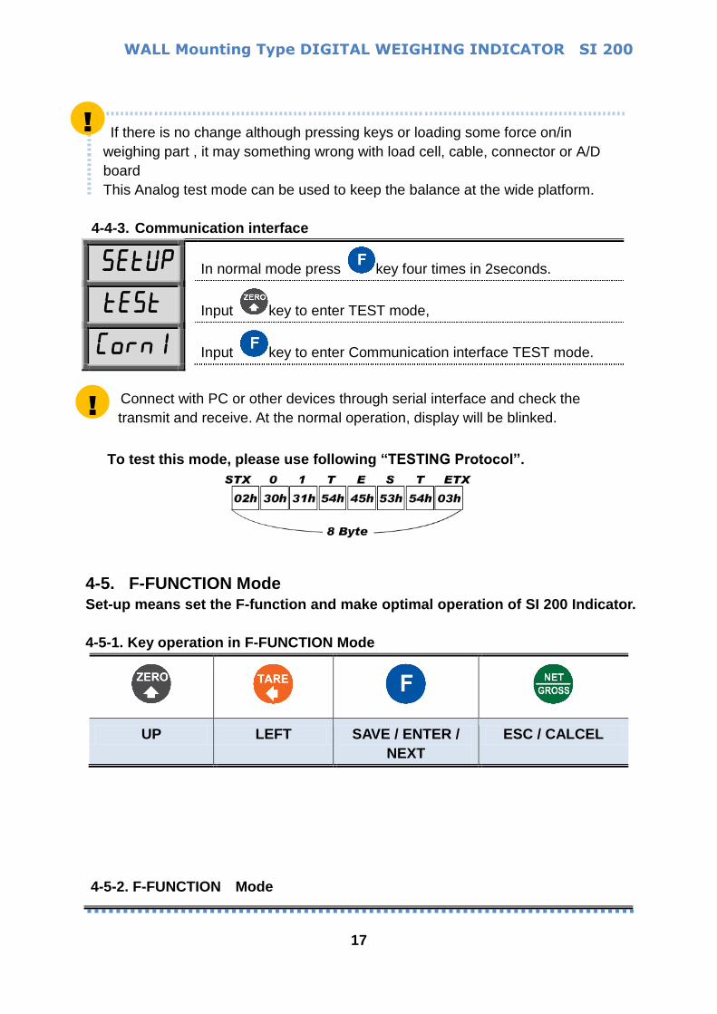
4-4-3. Communication interface
5etUp In normal mode press key four times in 2seconds.
te5t Input key to enter TEST mode,
Corn1 Input key to enter Communication interface TEST mode.
Connect with PC or other devices through serial interface and check the
transmit and receive. At the normal operation, display will be blinked.
To test this mode, please use following “TESTING Protocol”.
4-5. F-FUNCTION Mode
Set-up means set the F-function and make optimal operation of SI 200 Indicator.
4-5-1. Key operation in F-FUNCTION Mode
UP LEFT SAVE / ENTER /
NEXT
ESC / CALCEL
4-5-2. F-FUNCTION Mode
!
WALL Mounting Type DIGITAL WEIGHING INDICATOR SI 200
18
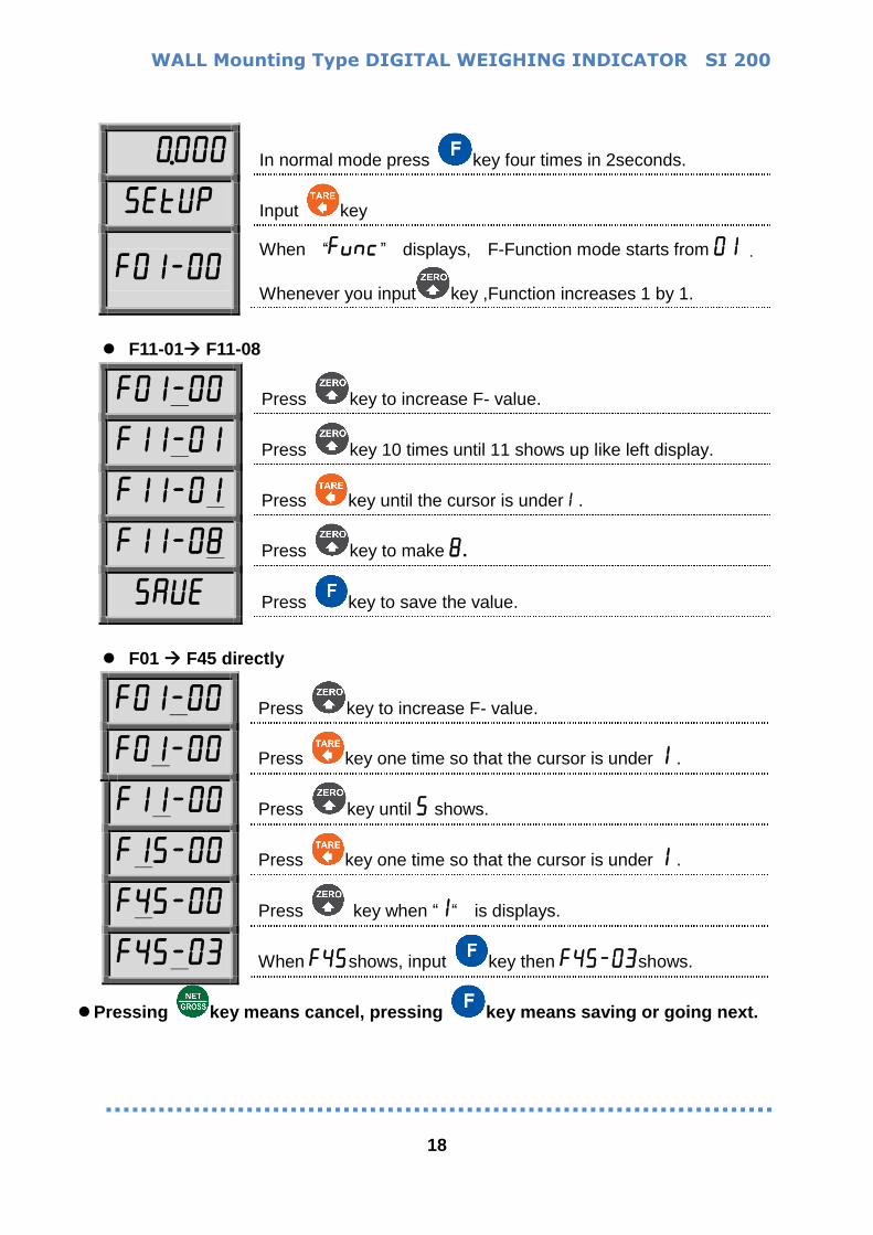
0.000 In normal mode press key four times in 2seconds.
5etUp Input key
f01-00 When “func” displays, F-Function mode starts from 01 .
Whenever you input key ,Function increases 1 by 1.
F11-01 F11-08
f01-00 Press key to increase F- value.
f11-01 Press key 10 times until 11 shows up like left display.
f11-01 Press key until the cursor is under1 .
f11-08 Press key to make 8.
5aUe Press key to save the value.
F01 F45 directly
f01-00 Press key to increase F- value.
f01-00 Press key one time so that the cursor is under 1 .
f11-00 Press key until 5 shows.
f15-00 Press key one time so that the cursor is under 1 .
f45-00 Press key when “1“ is displays.
f45-03 When f45shows, input key then f45-03shows.
Pressing key means cancel, pressing key means saving or going next.
WALL Mounting Type DIGITAL WEIGHING INDICATOR SI 200
19
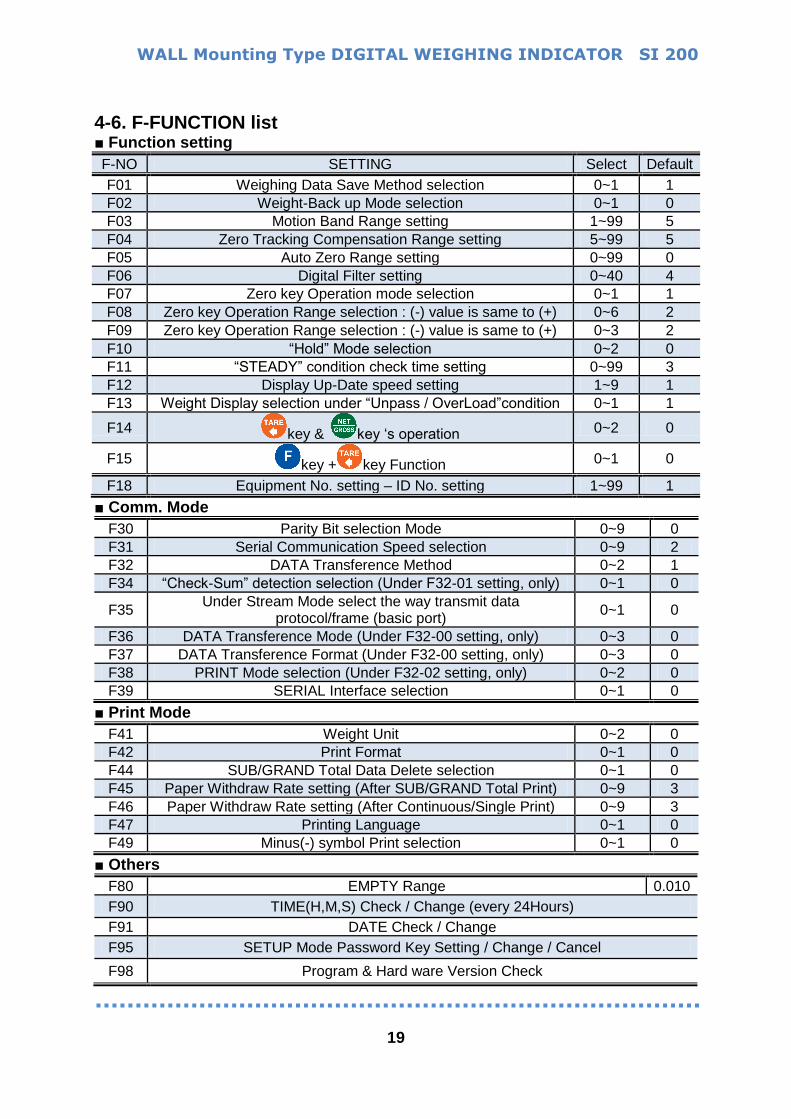
4-6. F-FUNCTION list Function setting
F-NO SETTING Select Default
F01 Weighing Data Save Method selection 0~1 1
F02 Weight-Back up Mode selection 0~1 0
F03 Motion Band Range setting 1~99 5
F04 Zero Tracking Compensation Range setting 5~99 5
F05 Auto Zero Range setting 0~99 0
F06 Digital Filter setting 0~40 4
F07 Zero key Operation mode selection 0~1 1
F08 Zero key Operation Range selection : (-) value is same to (+) 0~6 2
F09 Zero key Operation Range selection : (-) value is same to (+) 0~3 2
F10 “Hold” Mode selection 0~2 0
F11 “STEADY” condition check time setting 0~99 3
F12 Display Up-Date speed setting 1~9 1
F13 Weight Display selection under “Unpass / OverLoad”condition 0~1 1
F14 key & key ‘s operation 0~2 0
F15 key + key Function 0~1 0
F18 Equipment No. setting – ID No. setting 1~99 1
Comm. Mode
F30 Parity Bit selection Mode 0~9 0
F31 Serial Communication Speed selection 0~9 2
F32 DATA Transference Method 0~2 1
F34 “Check-Sum” detection selection (Under F32-01 setting, only) 0~1 0
F35 Under Stream Mode select the way transmit data
protocol/frame (basic port) 0~1 0
F36 DATA Transference Mode (Under F32-00 setting, only) 0~3 0
F37 DATA Transference Format (Under F32-00 setting, only) 0~3 0
F38 PRINT Mode selection (Under F32-02 setting, only) 0~2 0
F39 SERIAL Interface selection 0~1 0
Print Mode
F41 Weight Unit 0~2 0
F42 Print Format 0~1 0
F44 SUB/GRAND Total Data Delete selection 0~1 0
F45 Paper Withdraw Rate setting (After SUB/GRAND Total Print) 0~9 3
F46 Paper Withdraw Rate setting (After Continuous/Single Print) 0~9 3
F47 Printing Language 0~1 0
F49 Minus(-) symbol Print selection 0~1 0
Others
F80 EMPTY Range 0.010
F90 TIME(H,M,S) Check / Change (every 24Hours)
F91 DATE Check / Change
F95 SETUP Mode Password Key Setting / Change / Cancel
F98 Program & Hard ware Version Check
WALL Mounting Type DIGITAL WEIGHING INDICATOR SI 200
20
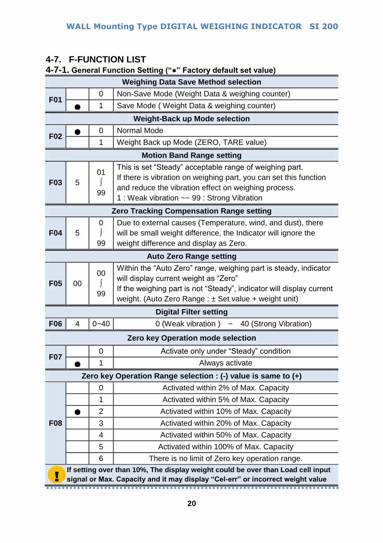
4-7. F-FUNCTION LIST 4-7-1. General Function Setting (“” Factory default set value)
Weighing Data Save Method selection
F01 0 Non-Save Mode (Weight Data & weighing counter)
1 Save Mode ( Weight Data & weighing counter)
Weight-Back up Mode selection
F02 0 Normal Mode
1 Weight Back up Mode (ZERO, TARE value)
Motion Band Range setting
F03 5
01
∫
99
This is set “Steady” acceptable range of weighing part.
If there is vibration on weighing part, you can set this function
and reduce the vibration effect on weighing process.
1 : Weak vibration ~~ 99 : Strong Vibration
Zero Tracking Compensation Range setting
F04 5
0
∫
99
Due to external causes (Temperature, wind, and dust), there
will be small weight difference, the Indicator will ignore the
weight difference and display as Zero.
Auto Zero Range setting
F05 00
00
∫
99
Within the “Auto Zero” range, weighing part is steady, indicator
will display current weight as “Zero”
If the weighing part is not “Steady”, indicator will display current
weight. (Auto Zero Range : ± Set value + weight unit)
Digital Filter setting
F06 4 0~40 0 (Weak vibration ) ~ 40 (Strong Vibration)
Zero key Operation mode selection
F07 0 Activate only under “Steady” condition
1 Always activate
Zero key Operation Range selection : (-) value is same to (+)
F08
0 Activated within 2% of Max. Capacity
1 Activated within 5% of Max. Capacity
2 Activated within 10% of Max. Capacity
3 Activated within 20% of Max. Capacity
4 Activated within 50% of Max. Capacity
5 Activated within 100% of Max. Capacity
6 There is no limit of Zero key operation range.
If setting over than 10%, The display weight could be over than Load cell input
signal or Max. Capacity and it may display “Cel-err” or incorrect weight value !
WALL Mounting Type DIGITAL WEIGHING INDICATOR SI 200
21
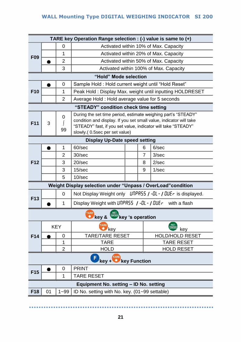
TARE key Operation Range selection : (-) value is same to (+)
F09
0 Activated within 10% of Max. Capacity
1 Activated within 20% of Max. Capacity
2 Activated within 50% of Max. Capacity
3 Activated within 100% of Max. Capacity
“Hold” Mode selection
F10
0 Sample Hold : Hold current weight until “Hold Reset”
1 Peak Hold : Display Max. weight until inputting HOLDRESET
2 Average Hold : Hold average value for 5 seconds
“STEADY” condition check time setting
F11 3
0
∫
99
During the set time period, estimate weighing part’s “STEADY”
condition and display. If you set small value, indicator will take
“STEADY” fast, if you set value, indicator will take “STEADY”
slowly.( 0.5sec per set value)
Display Up-Date speed setting
F12
1 60/sec 6 6/sec
2 30/sec 7 3/sec
3 20/sec 8 2/sec
3 15/sec 9 1/sec
5 10/sec
Weight Display selection under “Unpass / OverLoad”condition
F13 0 Not Display Weight only UNpa55 / –0l- / 0Uer is displayed.
1 Display Weight with UNpa55S/ –0l- / 0Uer with a flash
key & key ‘s operation
F14
KEY key key
0 TARE/TARE RESET HOLD/HOLD RESET
1 TARE TARE RESET
2 HOLD HOLD RESET
key + key Function
F15 0 PRINT
1 TARE RESET
Equipment No. setting – ID No. setting
F18 01 1~99 ID No. setting with No. key. (01~99 settable)

WALL Mounting Type DIGITAL WEIGHING INDICATOR SI 200
22
4-7-1. Communication Mode Setting
Parity Bit selection Mode
F30
0 DATA Bit (8 Bit) STOP Bit (1 Bit) Parity Bit (Non)
1 DATA Bit (8 Bit) STOP Bit (1 Bit) Parity Bit (Odd)
2 DATA Bit (8 Bit) STOP Bit (1 Bit) Parity Bit (Even)
3 DATA Bit (8 Bit) STOP Bit (2 Bit) Parity Bit (Non)
4 DATA Bit (8 Bit) STOP Bit (2 Bit) Parity Bit (Odd)
5 DATA Bit (8 Bit) STOP Bit (2 Bit) Parity Bit (Even)
6 DATA Bit (7 Bit) STOP Bit (1 Bit) Parity Bit (Odd)
7 DATA Bit (7 Bit) STOP Bit (1 Bit) Parity Bit (Even)
8 DATA Bit (7 Bit) STOP Bit (2 Bit) Parity Bit (Odd)
9 DATA Bit (7 Bit) STOP Bit (2 Bit) Parity Bit (Even)
Serial Communication Speed selection
F31
0 2,400bps
1 4,800bps
2 9,600bps
3 14,400bps
4 19,200bps
5 28,800bps
6 38,400bps
7 57,600bps
8 76,800bps
9 115,200bps
DATA Transference Method
F32
0 Simplex Mode / Stream Mode
1 Duplex Mode / Command Mode
2 PRINT Mode
“Check-Sum” detection selection (Under F32-01 setting, only)
F34 0 Check-Sum Not Use
1 Check-Sum Use
Under Stream Mode select the way transmit data protocol/frame (basic port)
F35 0 Transmit by Protocol
1 Transmit by frame (in case of using specific utility)
In case of “Transmit by frame” & under 14,400bps setting(F31), the speed of
system will be slow.

WALL Mounting Type DIGITAL WEIGHING INDICATOR SI 200
23
DATA Transference Mode (Under F32-00 setting, only)
F36
0 Always
1 Single time data transference, Whenever the weight is steady
over Empty range.
2 Single time data transference, at first steady point, over Empty
range.
3 Data transference, Whenever INPUT “Print” key input
DATA Transference Format (Under F32-00 setting, only)
F37
0 Format 1 (recommended when use external display)
1 Format 2. (Format 1 + ID No.)
2 Format 3. (recommended when connecting to PLC or PC)
3 CAS Format
PRINT Mode selection (Under F32-02 setting, only)
F38
0 Manual
PRINT When inputting Key + Key
1 Auto
When inputting
Key + Key
At the first Steady point over
“EMPTY” range
2 Every Steady state at over
“EMPTY” range
SERIAL Interface selection
F39 0 RS-232C. (Side Switch UP)
1 RS-485 (Side Switch DOWN)
Print Mode Setting
Weight Unit
F41
0 Kg
1 g
2 t
Print Format
F42 0
Continuous Print - Serial No. and Weight will be printed
continuously.
1 Single Print - Date, Time, S/N, ID No. Weighing Data will be print
SUB/GRAND Total Data Delete selection
F44 0 Not deleted (= manual Delete mode)
1 Automatically Deleted.-After print out SBU/GRAND Total.
Paper Withdraw Rate setting (After SUB/GRAND Total Print)
F45 3 0~9 Whenever set value increased as 1, then 1 line will be added.
WALL Mounting Type DIGITAL WEIGHING INDICATOR SI 200
24
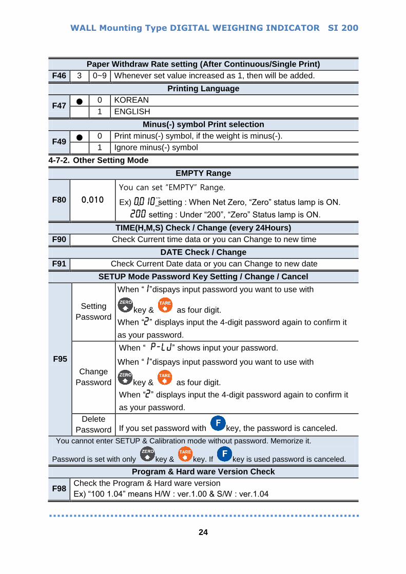
Paper Withdraw Rate setting (After Continuous/Single Print)
F46 3 0~9 Whenever set value increased as 1, then will be added.
Printing Language
F47 0 KOREAN
1 ENGLISH
Minus(-) symbol Print selection
F49 0 Print minus(-) symbol, if the weight is minus(-).
1 Ignore minus(-) symbol
4-7-2. Other Setting Mode
EMPTY Range
F80 0.010
You can set “EMPTY” Range.
Ex) 0.010" setting : When Net Zero, “Zero” status lamp is ON.
200 setting : Under “200”, “Zero” Status lamp is ON.
TIME(H,M,S) Check / Change (every 24Hours)
F90 Check Current time data or you can Change to new time
DATE Check / Change
F91 Check Current Date data or you can Change to new date
SETUP Mode Password Key Setting / Change / Cancel
F95
Setting
Password
When “1”dispays input password you want to use with
key & as four digit.
When “2” displays input the 4-digit password again to confirm it
as your password.
Change
Password
When “Pp-lj” shows input your password.
When “1”dispays input password you want to use with
key & as four digit.
When “2” displays input the 4-digit password again to confirm it
as your password.
Delete
Password If you set password with key, the password is canceled.
You cannot enter SETUP & Calibration mode without password. Memorize it.
Password is set with only key & key. If key is used password is canceled.
Program & Hard ware Version Check
F98 Check the Program & Hard ware version
Ex) “100 1.04” means H/W : ver.1.00 & S/W : ver.1.04

WALL Mounting Type DIGITAL WEIGHING INDICATOR SI 200
25
5. INTERFACE
5-1. Serial Interface RS – 232C (F39-00 setting – Side switch up - standard)
5-2. Serial Interface RS-485 (F39-01 setting – Side switch down )
Serial communication interface is sensitive to electric noise.
Install isolated place from Power cable or other electric cables and wires,
and please use shielded cable for better performance.
OR
OR
MAX 32 pcs of Indicators are connectable
!
PCL
WALL Mounting Type DIGITAL WEIGHING INDICATOR SI 200
26
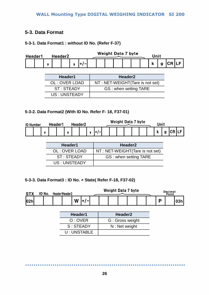
5-3. Data Format 5-3-1. Data Format1 : without ID No. (Refer F-37)
Header1 Header2
OL : OVER LOAD NT : NET-WEIGHT(Tare is not set)
ST : STEADY GS : when setting TARE
US : UNSTEADY
5-3-2. Data Format2 (With ID No. Refer F- 18, F37-01)
Header1 Header2
OL : OVER LOAD NT : NET-WEIGHT(Tare is not set)
ST : STEADY GS : when setting TARE
US : UNSTEADY
5-3-3. Data Format3 : ID No. + State( Refer F-18, F37-02)
Header1 Header2
O : OVER G : Gross weight
S : STEADY N : Net weight
U : UNSTABLE
WALL Mounting Type DIGITAL WEIGHING INDICATOR SI 200
27
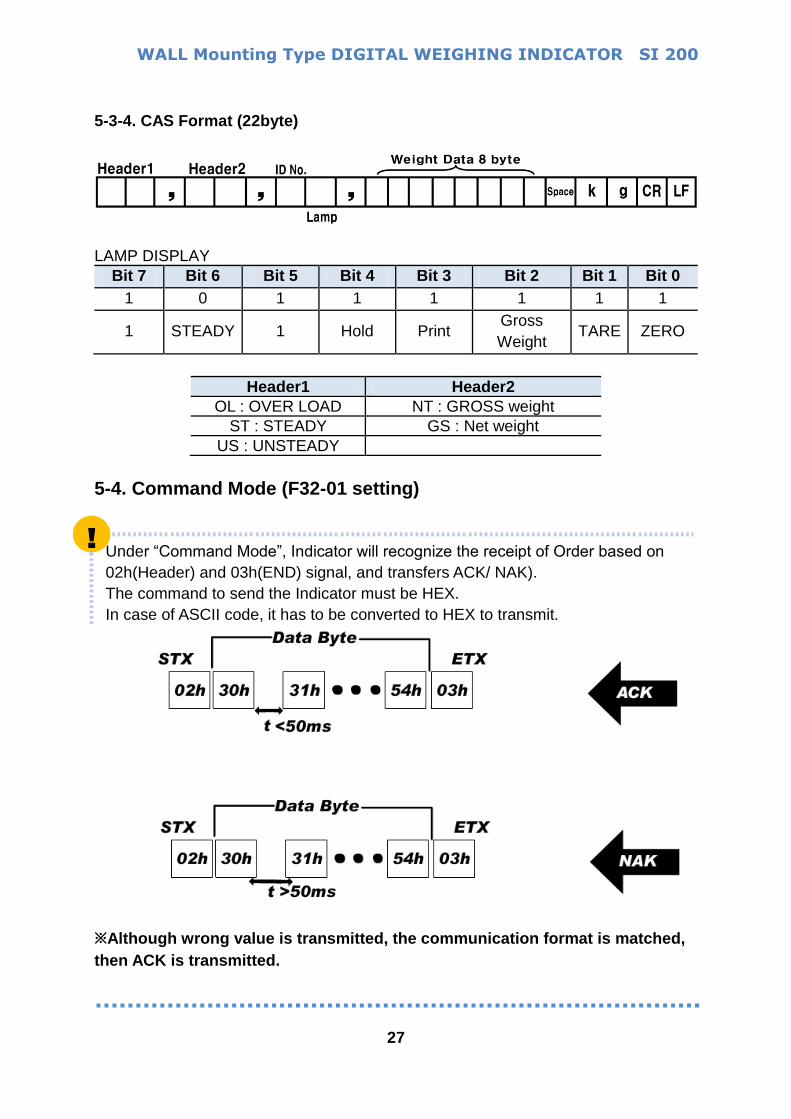
5-3-4. CAS Format (22byte)
LAMP DISPLAY
Bit 7 Bit 6 Bit 5 Bit 4 Bit 3 Bit 2 Bit 1 Bit 0
1 0 1 1 1 1 1 1
1 STEADY 1 Hold Print Gross
Weight TARE ZERO
Header1 Header2
OL : OVER LOAD NT : GROSS weight
ST : STEADY GS : Net weight
US : UNSTEADY
5-4. Command Mode (F32-01 setting)
Under “Command Mode”, Indicator will recognize the receipt of Order based on
02h(Header) and 03h(END) signal, and transfers ACK/ NAK).
The command to send the Indicator must be HEX.
In case of ASCII code, it has to be converted to HEX to transmit.
※Although wrong value is transmitted, the communication format is matched,
then ACK is transmitted.
!

WALL Mounting Type DIGITAL WEIGHING INDICATOR SI 200
28
5-4-1. Read Command The min. interval of read command is 100ms. (In case of check-sum 150ms)
Current Weight data
PC SI200
Read
ASCII STX ID(2Byte) RCWT ETX
HEX 02 30 31 52 43 57 54 03
SI 200 PC
Respond
STX ID RCWT State1(1byte) State2(1byte) P decimal point(1byte) +/-
(1byte) Current weight(7byte) Weight unit(2byte) ETX
State1 : O(Over load) , S(Steady), U(Unsteady)
State2 : N(Net weight), G(Gross weight)
Ex) Steady(S), TARE not used(N), 0.000kg
Indicator memory data
PC SI200
Read
ASCII STX ID(2Byte) RCWD ETX
HEX 02 30 31 52 43 57 44 03
SI 200 PC
Respond
STX ID RCWD P decimal point(1byte)DATE(6byte) TIME(6byte) the no. of
weighing (6byte) +/- TARE(7Byte) +/- current weight(7byte) unit(2byte) ETX
Ex) DATE : Aug 12th,2009, TIME : 12:00:00, the no. of weighing : 10, TARE : 2.000kg,
current weight : 3.000kg
Grand Total
PC SI200
Read
ASCII STX ID(2Byte) RGRD ETX
HEX 02 30 31 52 43 57 44 03
SI 200 PC
Respond
STX ID RGRD P decimal point(1byte)Accumulated S/N count (6byte)
Accumulated weight(10byte) weight unit(2byte) ETX
Ex) the no. of weighing : 10 , Accumulated Weight : 10.000kg
Current Time
PC SI200
Read
ASCII STX ID(2Byte) RTIM ETX
HEX 02 30 31 52 54 49 4D 03
SI 200 PC Respond STX ID RDAT Current Date(6byte) ETX
Ex) Time : 12:00:00
WALL Mounting Type DIGITAL WEIGHING INDICATOR SI 200
29
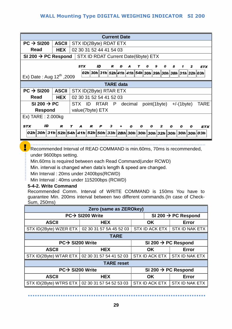
Current Date
PC SI200
Read
ASCII STX ID(2Byte) RDAT ETX
HEX 02 30 31 52 44 41 54 03
SI 200 PC Respond STX ID RDAT Current Date(6byte) ETX
Ex) Date : Aug 12th ,2009
TARE data
PC SI200
Read
ASCII STX ID(2Byte) RTAR ETX
HEX 02 30 31 52 54 41 52 03
SI 200 PC
Respond
STX ID RTAR P decimal point(1byte) +/-(1byte) TARE
value(7byte) ETX
Ex) TARE : 2.000kg
Recommended Interval of READ COMMAND is min.60ms, 70ms is recommended,
under 9600bps setting.
Min.60ms is required between each Read Command(under RCWD)
Min. interval is changed when data’s length & speed are changed.
Min Interval : 20ms under 2400bps(RCWD)
Min Interval : 40ms under 115200bps (RCWD)
5-4-2. Write Command Recommended Comm. Interval of WRITE COMMAND is 150ms You have to guarantee Min. 200ms interval between two different commands.(In case of Check-Sum, 250ms)
Zero (same as ZEROkey)
PC SI200 Write SI 200 PC Respond
ASCII HEX OK Error
STX ID(2Byte) WZER ETX 02 30 31 57 5A 45 52 03 STX ID ACK ETX STX ID NAK ETX
TARE
PC SI200 Write SI 200 PC Respond
ASCII HEX OK Error
STX ID(2Byte) WTAR ETX 02 30 31 57 54 41 52 03 STX ID ACK ETX STX ID NAK ETX
TARE reset
PC SI200 Write SI 200 PC Respond
ASCII HEX OK Error
STX ID(2Byte) WTRS ETX 02 30 31 57 54 52 53 03 STX ID ACK ETX STX ID NAK ETX
!
WALL Mounting Type DIGITAL WEIGHING INDICATOR SI 200
30
!
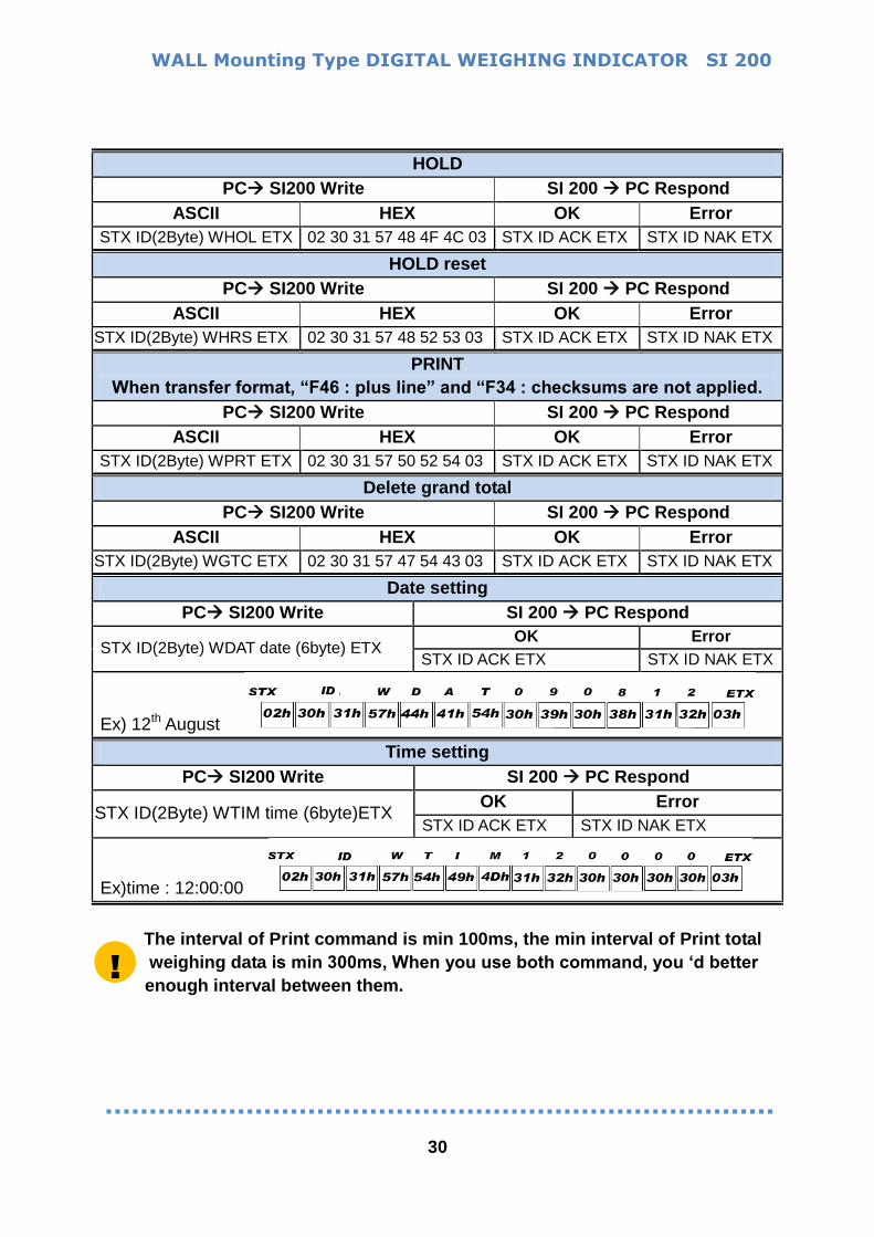
HOLD
PC SI200 Write SI 200 PC Respond
ASCII HEX OK Error
STX ID(2Byte) WHOL ETX 02 30 31 57 48 4F 4C 03 STX ID ACK ETX STX ID NAK ETX
HOLD reset
PC SI200 Write SI 200 PC Respond
ASCII HEX OK Error
STX ID(2Byte) WHRS ETX 02 30 31 57 48 52 53 03 STX ID ACK ETX STX ID NAK ETX
When transfer format, “F46 : plus line” and “F34 : checksums are not applied.
PC SI200 Write SI 200 PC Respond
ASCII HEX OK Error
STX ID(2Byte) WPRT ETX 02 30 31 57 50 52 54 03 STX ID ACK ETX STX ID NAK ETX
Delete grand total
PC SI200 Write SI 200 PC Respond
ASCII HEX OK Error
STX ID(2Byte) WGTC ETX 02 30 31 57 47 54 43 03 STX ID ACK ETX STX ID NAK ETX
Date setting
PC SI200 Write SI 200 PC Respond
STX ID(2Byte) WDAT date (6byte) ETX OK Error
STX ID ACK ETX STX ID NAK ETX
Ex) 12th August
Time setting
PC SI200 Write SI 200 PC Respond
STX ID(2Byte) WTIM time (6byte)ETX OK Error
STX ID ACK ETX STX ID NAK ETX
Ex)time : 12:00:00
The interval of Print command is min 100ms, the min interval of Print total
weighing data is min 300ms, When you use both command, you ‘d better
enough interval between them.
WALL Mounting Type DIGITAL WEIGHING INDICATOR SI 200
31
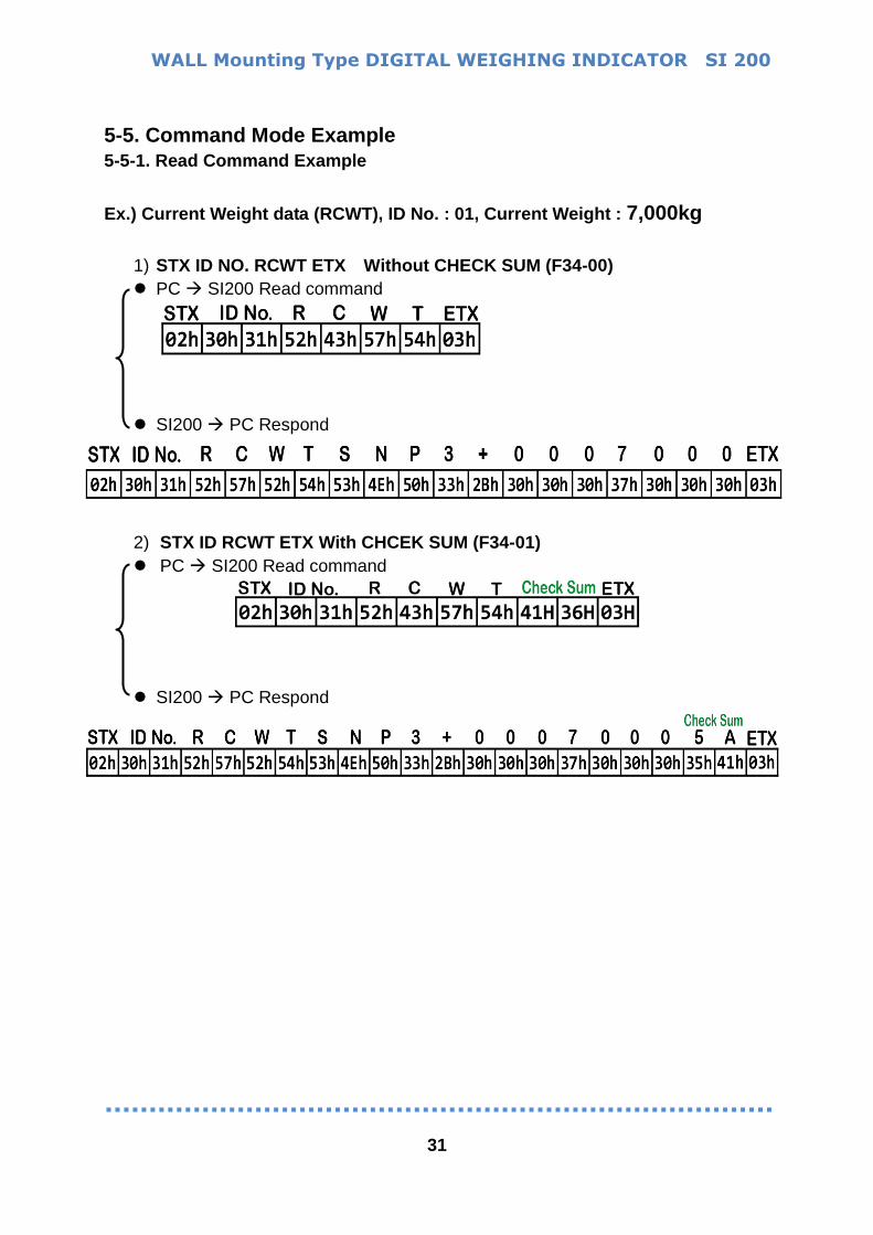
5-5. Command Mode Example
5-5-1. Read Command Example
Ex.) Current Weight data (RCWT), ID No. : 01, Current Weight : 7,000kg
1) STX ID NO. RCWT ETX Without CHECK SUM (F34-00)
PC SI200 Read command
SI200 PC Respond
2) STX ID RCWT ETX With CHCEK SUM (F34-01)
PC SI200 Read command
SI200 PC Respond
WALL Mounting Type DIGITAL WEIGHING INDICATOR SI 200
32
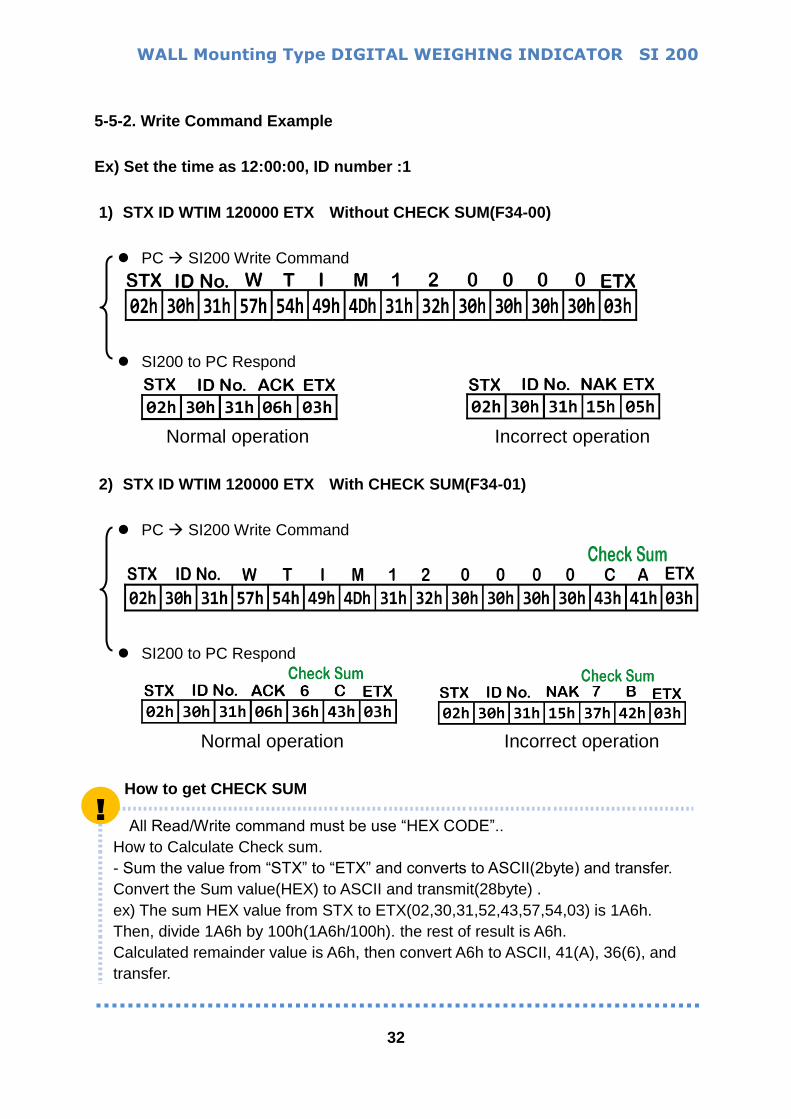
5-5-2. Write Command Example
Ex) Set the time as 12:00:00, ID number :1
1) STX ID WTIM 120000 ETX Without CHECK SUM(F34-00)
PC SI200 Write Command
SI200 to PC Respond
Normal operation Incorrect operation
2) STX ID WTIM 120000 ETX With CHECK SUM(F34-01)
PC SI200 Write Command
SI200 to PC Respond
Normal operation Incorrect operation
How to get CHECK SUM
All Read/Write command must be use “HEX CODE”..
How to Calculate Check sum.
- Sum the value from “STX” to “ETX” and converts to ASCII(2byte) and transfer.
Convert the Sum value(HEX) to ASCII and transmit(28byte) .
ex) The sum HEX value from STX to ETX(02,30,31,52,43,57,54,03) is 1A6h.
Then, divide 1A6h by 100h(1A6h/100h). the rest of result is A6h.
Calculated remainder value is A6h, then convert A6h to ASCII, 41(A), 36(6), and
transfer.
!

WALL Mounting Type DIGITAL WEIGHING INDICATOR SI 200
33
5-6. Print interface
It can be connected with all kinds of Serial interface printer, but the printing format is already programmed and fixed with our SE7200/7300 model.
Printing Format (F32-02 under setting)
KOREAN (F47-00) ENGLISH (F47-01)
Continuous
Format
F42-00
Single Print
Format
F42-01
Grand Total
F44-00

WALL Mounting Type DIGITAL WEIGHING INDICATOR SI 200
34
6. Error & Treatment 6-1. Load Cell Installation
Error Cause Treatment Remark
Unstable
display
1) Load cell problem
2)Load cell isolation
resistance error
3)Contact, touch problem
4) Summing box problem
1) Measure input or
output resistance of
Load cell.
2) Measure Load
cell isolation
resistance
1. Input Resistance of “EXC+”
and “EXC-“ is about 400Ω. ±3
2. Output Resistance of
“SIG+“ and “SIG-” is about
350Ω. ±3.5
3. Isolate Resistance is more
than 100Ω
Weight doesn’t
return to “Zero”
1) Load cell problem
2) Load cell wiring contact
problem
1) Check Load cell connection
2) Measure Load cell Resistance
Display under(-
) zero although
you load
something
the switched Load cell output wires (SIG+,SIG-) Load cell Check
Load cell connection
Check
Calibrate weight again
right after
calibration
display
“UNpa55"
Load cell broken or Indicator connection Error
Power was “ON” when some weight is on the load cell.
display
“-0l-””0Uer”
(OVER LOAD)
1) Load cell broken or
Indicator connection Error
2) Loading over than
Max. Capacity.
1) Load cell or connection
Check
3) Remove the loaded weight
4) Calibrate again
Double TARE(F
key+ TARE key) is
applied too many.
(over limit capa)
6-2. Calibration Process
Display Cause
err-1 It shows in case of .
Ex) Rated capa[Max capa] is 20,000 , division[Min unit] cannot be under 1
err-4 It shows when the Test weight > Rated capa[Max capa]
Then please re-input right value again.
The more heavy test weight makes the more accurate measurement.
err-5 It shows when the Test weight < 10% of Rated capa[Max capa]
Then Please re-input right value agian.
err-6 Amp. Gain is too big / Sig+/- wiring is connected wrongly. / The test weight is not
loaded.
err-7 Amp. Gain is too small / Sig+/- wiring is connected wrongly. /
The test weight is not loaded.
err-8 Under “F-function” model, set value is appropriate.
err-a there is vibration on the load cell or load cell wire, the indicator cannot calibrate
anymore.

WALL Mounting Type DIGITAL WEIGHING INDICATOR SI 200
35
6-3. Digital Weighing Indicator
Display Cause Treatment
Cell-er
OR
0Uer
1. Load cell Error
2. Load cell cable Error
3.Load cell connection Error
4. A/D Board Error
5.If Analogue value
is over 1,040,000.
※ When weigh “-“ value,
If it is over set max capa,
“OVER” is displayed.
Ex) Even though set max capa
is “100” and it is over “-100”,
“0Uer” is displayed.
1. Under “TEST” mode 1, check
analogue value. If you cannot get
any analogue value or there is no
change although adding load,
please check load cell, load cell
cable, connection conditions first.
2. Replace another load cell, and
check the indicator condition. If
you have same problem, please
replace new indicator and check
A/D board error.
3. Try to connect the indicator’s A/D
with the other indicator.
4. Check the power and load cell
connection of terminal.
※ In this situation ZERO key & PRINT
key are not activated.
UNpa55
1. Power is ON, when some
materials are on weighing
part.
※ Under “Normal Mode”, if
there are more than 20%
loading of Max. capacity,
“UNpa55” display will be
appeared and indicator will
stay until removing the load.
※Setting Back-up mode it can
memory empty value, and it
becomes set value without
displaying” Un-pass”)
1. If you set “Normal Mode”, please
check weighing part empty or not
before turn on the power. If there
are some materials in/on weighing
part, please remove those
materials and turn on the power.
2. Please try to set F02-01(Back-up)
mode so that the indicator can
remember first empty value.
5et EEPROM problem Please contact the distributor or
Head Office. Halt H/W Problem
5t-err The Error about Time
WALL Mounting Type DIGITAL WEIGHING INDICATOR SI 200
36
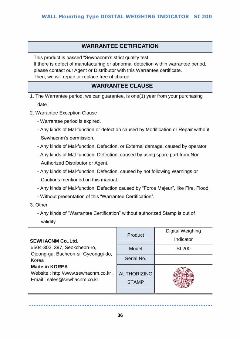
WARRANTEE CETIFICATION
This product is passed “Sewhacnm’s strict quality test.
If there is defect of manufacturing or abnormal detection within warrantee period,
please contact our Agent or Distributor with this Warrantee certificate.
Then, we will repair or replace free of charge.
WARRANTEE CLAUSE
1. The Warrantee period, we can guarantee, is one(1) year from your purchasing
date
2. Warrantee Exception Clause
- Warrantee period is expired.
- Any kinds of Mal-function or defection caused by Modification or Repair without
Sewhacnm’s permission.
- Any kinds of Mal-function, Defection, or External damage, caused by operator
- Any kinds of Mal-function, Defection, caused by using spare part from Non-
Authorized Distributor or Agent.
- Any kinds of Mal-function, Defection, caused by not following Warnings or
Cautions mentioned on this manual.
- Any kinds of Mal-function, Defection caused by “Force Majeur”, like Fire, Flood.
- Without presentation of this “Warrantee Certification”.
3. Other
- Any kinds of “Warrantee Certification” without authorized Stamp is out of
validity
SEWHACNM Co.,Ltd.
#504-302, 397, Seokcheon-ro,
Ojeong-gu, Bucheon-si, Gyeonggi-do,
Korea
Made in KOREA
Website : http://www.sewhacnm.co.kr ,
Email : [email protected]
Product Digital Weighing
Indicator
Model SI 200
Serial No.
AUTHORIZING
STAMP