nasa - stockflightsystems.com · revision 1.7, 12.1.2006 3/57 (c) 1998-2006 stock flight systems...
TRANSCRIPT

Interfacespecification for airborne CANapplications
V 1.7
NASAAGATE data bus

Revision 1.7, 12.1.2006 1/57 (C) 1998-2006 Stock Flight Systems
Revision history
Ver. Who When What
1.0 M. Stock 10.10.98 Initial Version
1.05 M. Stock 5.11.98 Identifier lists modified
1.1 M. Stock 10.01.99 MIL connector definitionsadded
1.2 M. Stock 20.01.99 Navigation identifiers added
1.3 M. Stock 14.04.99 Engine/Fuel system parame-ter definitions changed, multi-ple data type support added
1.4 M. Stock 12.07.99 NAV section rearranged, newdata types added
1.5 M. Stock 02.02.00 Connector definitions up-dated, some data normalized
1.6 M. Stock 13.03.01 Redundancy support andtime triggered bus schedulingadded
1.7 M. Stock 12.01.06 Identifier distribution listexpanded, several nodeservices added, clarifications
Copyright statement
CANaerospace is an interface standard open to everyone. No copy-rights are reserved and no licenses are necessary for its implementati-on, use or distribution. Consequently, the author explicitely refusesany responsibility arising from the use of this standard in any applicati-on. This document in its current version is available from:
www.canaerospace.com
Comments to this standard are welcome:
Stock Flight SystemsSchützenweg 8a82335 Berg/FarchachGermanyphone.: +49-8151-9607-0fax: +49-8151-9607-30Email: [email protected]
Front cover photograph: NASA test pilot Rogers Smith flying the X-29 research aircraftover Mojave Desert, California

Revision 1.7, 12.1.2006
Table of Contents
Section Page
1 Introduction 4
2 Message data types and identifier assignment 4
2.1 Message types 4
2.2 Data types 5
3 Message structure 7
3.1 General message format 8
3.2 Emergency event data (EED) format 9
3.3 Normal operation data (NOD) message format 9
3.4 Node service data (NSH/NSL) message format 9
3.5 Debug service data (DSD) message format 9
3.6 User-defined data (UDH/UDL) message format 9
4 Node service protocol 10
4.1 Identification service (IDS) 13
4.2 Node synchronisation service (HSS) 14
4.3 Data download service (DDS) 15
4.4 Data upload service (DUS) 16
4.5 Simulation control service (SCS) 17
4.6 Transmission interval service (TIS) 17
4.7 FLASH programming service (FPS) 18
4.8 State transmission service (STS) 19
4.9 Filter setting service (FSS) 19
4.10 Test control service (TCS) 19
4.11 Baudrate setting service (BSS) 20
4.12 Node-ID setting service (NIS) 20
4.13 Module information service (MIS) 21
4.14 Module configuration service (MCS) 21
4.15 CAN-ID setting service (CSS) 22
4.16 CAN-ID distribution setting service (DIS) 22
5 CANaerospace default identifier distribution 24
5.1 Flight state/air data 26
5.2 Flight controls data 28
5.3 Aircraft engine/fuel system data 31
2/57 (C) 1998-2006 Stock Flight Systems

Revision 1.7, 12.1.2006
Table of Contents
Section Page
5.4 Power transmission system data 35
5.5 Hydraulic system data 35
5.6 Electric system data 36
5.7 Navigation system data 36
5.8 Landing gear system data 44
5.9 Miscellaneous data 44
5.10 Reserved data 45
6 Time-triggered bus scheduling 46
6.1 Baseline system 46
6.2 The transmission slot concept 47
6.3 Bus load computation 52
7 System redundancy support 53
7.1 Redundant message identifier assignment 53
7.2 Redundancy and the CANaerospace header 54
8 Physical connector definition 55
3/57 (C) 1998-2006 Stock Flight Systems

Revision 1.7, 12.1.2006
2.1 Message types
1 Introduction
CANaerospace is an extremely lightweight protocol/data format defini-tion which was designed for the highly reliable communication ofmicrocomputer-based systems in airborne applications via CAN (Con-troller Area Network). The purpose of this definition is to create a stan-dard for applications requiring an efficient data flow monitoring andeasy time-frame synchronisation within redundant systems. The defi-nition is kept widely open to allow implementation of user-definedmessage types and protocols. CANaerospace can be used with CAN2.0A and 2.0B (11-bit and 29-bit identifiers) and any bus data rate.
2 Message/data types and identifier assignment
The data format definition specifies 6 basic message types, which areused for different network services. Each message type has an asso-ciated CAN-ID range defining the message priority. Generally, theidentifier distribution within the specified ranges is at the user’s discre-tion. A standard CANaerospace identifier distribution addressing com-monly used data objects and devices in aerospace applications ismade in section 5, however. The use of this standard distribution sche-me is highly encouraged for interoperability reasons.
Message TypeCAN-IDRange
Explanation
EmergencyEvent Data(EED)
0 - 127
($000 - $07F)
Transmitted asynchronously whe-never a situation requiring imme-diate action occurs.
High PriorityNode ServiceData (NSH)
128 - 199
($080 - $0C7)
Transmitted asynchronously orcyclic with defined transmissionintervals for operational com-mands (36 channels)
High Priority-User-DefinedData (UDH)
200 - 299
($0C8 -$12B)
Message/data format and trans-mission intervals entirely user-de-fined
Normal Opera-tion Data(NOD)
300 - 1799
($12C - $707)
Transmitted asynchronously orcyclic with defined transmissionintervals for operational and sta-tus data.
Low Priority-User-DefinedData (UDL)
1800 - 1899
($708 - $76B)
Message/data format and trans-mission intervals entirely user-de-fined
4/57 (C) 1998-2006 Stock Flight Systems

Revision 1.7, 12.1.2006
2.2 Data types
For data representation, the most commonly used basic data typesare defined. Additionally, combined data types (i.e. two, three and four16 bit and 8 bit data types in one CAN message) and aggregate datatypes (64-bit double float) are supported. Other data types can be ad-ded to the type list as required. The type number in the range of 0-255is used for data type specification as described in section 3.1.DebugService Data(DSD)
1900 - 1999
($76C -$7CF)
Transmitted asynchronously orcyclic for debug communication &software download actions.
Low PriorityNode ServiceData (NSL)
2000 - 2031
$7D0 - $7EF
Transmitted asynchronously orcyclic for test & maintenance ac-tions (16 channels).
Data Type Range Bits Explanation Type #
NODATA n.a. 0 “No data” type 0($00)
ERROR n.a. 32 Emergency eventdata type
1($01)
FLOAT 1-bit sign23-bit fraction8-bit exponent
32 Single precisionfloating-point va-lue according toIEEE-754-1985
2($02)
LONG -2147483647 to+2147483648
32 2’s complementinteger
3($03)
ULONG 0 to4294967295
32 unsigned integer 4($04)
BLONG n.a. 32 Each bit defines adiscrete state. 32bits are coded intofour CAN data by-tes
5($05)
SHORT -32768 to+32767
16 2’s complementshort integer
6($06)
USHORT 0 to 65535 16 unsigned short in-teger
7($07)
Message TypeCAN-IDRange
Explanation
5/57 (C) 1998-2006 Stock Flight Systems

Revision 1.7, 12.1.2006
BSHORT n.a. 16 Each bit defines adiscrete state. 16bits are coded intotwo CAN data by-tes
8($08)
CHAR -128 to +127 8 2’s complementchar integer
9($09)
UCHAR 0 to 255 8 unsigned char in-teger
10($0A)
BCHAR n.a. 8 Each bit defines adiscrete state. 8bits are coded intoa single CAN databyte
11($0B)
SHORT2 -32768 to+32767
2 x16
2 x 2’s comple-ment short integer
12($0C)
USHORT2 0 to 65535 2 x16
2 x unsigned shortinteger
13($0D)
BSHORT2 n.a. 2 x16
2 x discrete short 14($0E)
CHAR4 -128 to +127 4 x8
4 x 2’s comple-ment char integer
15($0F)
UCHAR4 0 to 255 4 x8
4 x unsigned charinteger
16($10)
BCHAR4 n.a. 4 x8
4 x discrete char 17($11)
CHAR2 -128 to +127 2 x8
2 x 2’s comple-ment char integer
18($12)
UCHAR2 0 to 255 2 x8
2 x unsigned charinteger
19($13)
BCHAR2 n.a. 2 x8
2 x discrete char 20($14)
MEMID 0 to4294967295
32 Memory ID forupload/download
21($15)
CHKSUM 0 to4294967295
32 Checksum forupload/download
22($16)
ACHAR 0 to 255 8 ASCII character 23($17)
Data Type Range Bits Explanation Type #
6/57 (C) 1998-2006 Stock Flight Systems

Revision 1.7, 12.1.2006
3 Message structure
The coding of the data into the CAN message bytes is according to the“Big Endian” definition as used by Motorola 68K, SPARC, PowerPC,MIPS and other major processor architectures. All CAN messagesconsist of 4 header bytes for identification and between 1 and 4 databytes for the actual data.
ACHAR2 0 to 255 2 x8
2 x ASCIIcharacter
24($18)
ACHAR4 0 to 255 4 x8
4 xASCIIcharacter
25($19)
CHAR3 -128 to +127 3 x8
3 x 2’s comple-ment char integer
26($1A)
UCHAR3 0 to 255 3 x8
3 x unsigned charinteger
27($1B)
BCHAR3 n.a. 3 x8
3 x discrete char 28($1C)
ACHAR3 0 to 255 3 x8
4 xASCIIcharacter
29($1D)
DOUBLEH 1-bit sign52-bit fraction11-bit exponent
32 Most significant 32bits of double pre-cision floating-point value accor-ding to IEEE-754-1985
30($1E)
DOUBLEL 1-bit sign52-bit fraction11-bit exponent
32 Least significant32 bits of doubleprecision floating-point value accor-ding to IEEE-754-1985
31($1F)
RESVD n.a. xx Reserved for fu-ture use
32-99
($20-$63)
UDEF n.a. xx User-defined datatypes
100-255
($64-$FF)
Data Type Range Bits Explanation Type #
7/57 (C) 1998-2006 Stock Flight Systems

Revision 1.7, 12.1.2006
3.1 General messa-ge format
The general message format uses a 4 byte message header for nodeidentification, data type, message code and service code (for normaloperation data (NOD) , the service code field is user-defined). This al-lows identification of each message by any receiving unit without theneed for additional information. Every message type uses the samelayout for the CAN data bytes 0-3, while the number and the data typeused for CAN data bytes 4-7 is user-defined:
The header data fields have the following meaning:
• The node-ID is in the range of 0-255 with node-ID “0” beingthe broadcast-ID referring to “all nodes”. Note that for emer-gency event data (EED) and normal operation data (NOD)messages, the node-ID identifies the transmitting station,while for node service data (NSH/NSL) messages the node-ID identifies the addressed station.
• The data type specifies the coding of the data transportedwith the corresponding message. The number is taken fromthe data type list (see section 2.2).
• For normal operation data (NOD) messages, the messagecode is incremented by one for each message and may beused to monitor the sequence of incoming messages. Themessage code then rolls over to zero after passing 255. Thisfeature allows any node in the network to determine the ageof a signal and the proper sequence for monitoring purposes.For node service data (NSL/NSH) messages, however, themessage code is used for extended specification of the ser-vice.
• For normal operation data (NOD) messages, the servicecode consists of 8 bits which may be used as required by thespecific data (should be set to zero if unused). For node ser-vice data (NSL/NSH) messages, the service code containsthe node service code for the current operation.
Byte 4 Byte 5 Byte 6 Byte 7Byte 0 Byte 1 Byte 2 Byte 3
Message Data (message type specific)
Message Code (UCHAR)Service Code (xCHAR*)
Node-ID (UCHAR)
Message header
Data Type (UCHAR)
*: xCHAR may be CHAR, ACHAR, BCHAR or UCHAR
8/57 (C) 1998-2006 Stock Flight Systems

Revision 1.7, 12.1.2006
3.2 Emergency EventData (EED) mes-sage format
3.3 Normal Operati-on Data (NOD)message format
3.4 Node ServiceData (NSH/NSL)message format
3.5 Debug ServiceData (DSD) mes-sage format
3.6 User-DefinedData (UDL/UDH)message format
Emergency Event Data (EED) is transmitted asynchronously by the af-fected unit whenever an error situation occurs. The correspondingdata contains information about the location within the unit at whichthe error ocurred, the offending operation and the error code:
Normal Operation Data (NOD) is transmitted during normal operation,either cyclic or asynchronously. The data type (and therefore the mes-sage byte count) is taken from the data type list:
Node Service Data (NSH/NSL) is data associated to the node serviceprotocol as specified in section 4. The message format is similar toNOD. Node service data, however, is transmitted on specific identi-fiers only:
The Debug Service Data message format is entirely user-defined be-cause of the specific requirements resulting from the various host/tar-get communication protocols. Aside from using the specified identifierrange, no restrictions apply. To maximize flexibility, the message layoutand the data types must not follow any of the CANaerospace definiti-ons. It is encouraged, however, to use the proposed standard.
User-Defined Data message formats may be created for specific pur-poses. Aside from using the specified identifier range, no restrictionsapply. To maximize flexibility, the message layout and the data typesmust not follow any of the CANaerospace definitions. It is encouraged,however, to use the proposed standard.
Byte 4 Byte 5 Byte 6 Byte 7Byte 0 Byte 1 Byte 2 Byte 3
Message Header Message data (type/length as required)
Byte 4 Byte 5 Byte 6 Byte 7Byte 0 Byte 1 Byte 2 Byte 3
Message Header Error code (SHORT)OperationID (CHAR)LocationID (CHAR)
(Byte 1 = $01)
Byte 4 Byte 5 Byte 6 Byte 7Byte 0 Byte 1 Byte 2 Byte 3
Message Header Message data (type/length as required)
9/57 (C) 1998-2006 Stock Flight Systems

Revision 1.7, 12.1.2006
4 Node service protocol
In parallel to the data transfer during normal operation (EmergencyEvent Data, Normal Operation Data), the node service protocol provi-des a connection-oriented communication using a handshake mecha-nism. This protocol has been implemented to support command/response type connections between two nodes for specific operations,i.e. for data download or client/server actions. Note that node servicerequests requiring action but no response are possible as well. Re-quests of this type may be sent to a specific or all nodes (broadcast).
The node service protocol may be run either in high priority or lowpriority mode, selected by identifier. For the high priority mode, 36node service communication channels are available, while the lowpriority mode offers 16 communication channels. Each communicationchannel consists of one CAN identifier for the node service requestand the immediately following one for the node service response. Theidentifier assignment for the high priority node service channels is asfollows:
This is the identifier assignment for the low priority node service chan-nels:
Node ServiceChannel
Node ServiceRequest ID
Node ServiceResponse ID
0 128 ($080) 129 ($081)
1 130 ($082) 131 ($083)
2 132 ($084) 133 ($085)
....... ....... ......
....... ....... ......
33 194 ($0C2) 195 ($0C3)
34 196 ($0C4) 197 ($0C5)
35 198 ($0C6) 199 ($0C7)
Node ServiceChannel
Node ServiceRequest ID
Node ServiceResponse ID
100 2000 ($7D0) 2001 ($7D1)
101 2002 ($7D2) 2003 ($7D3)
10/57 (C) 1998-2006 Stock Flight Systems

Revision 1.7, 12.1.2006
A node service is initiated by a node service request message, trans-mitted on the corresponding identifier. All nodes attached to the net-work are obliged to continously monitor these identifiers and check ifreceived messages contain the own personal node-ID. If a match isdetected, the corresponding node has to react by performing the re-quired action and transmitting a node service response message onthe corresponding identifier within 100ms (if this was required by therequest type). The node service response must again contain the per-sonal node-ID of the addressed node. Any node in the network is allo-wed to initiate node services. It is recommended, however, that eachnode in the network initiating node service requests uses a dedicatednode service channel to avoid potential hand-shaking conflicts. Thechannel on which a particular node service is run may be defined bythe user. If only one service channel is used, node services must berun on channel 0 by default. Some frequently used types of node ser-vices are already specified below, other services may be added as re-quired.
Each CANaerospace unit must support at least the IdentificationService (IDS) on Node Service Channel 0. This makes sure that aCANaerospace network can be scanned for attached units to de-termine their status, header type and identifier assignment. Notethat within a CANaerospace network, other header types than thestandard CANaerospace header and several identifier assign-ment schemes (including entirely user-defined ones) are suppor-ted. Whenever possible, it is strongly recommended to use theproposed standard header and identifier assignment, however.
102 2004 ($7D4) 2005 ($7D5)
....... ....... ......
115 2030($7EE) 2031 ($7EF)
NodeService
ServiceCode
ResponseRequired
Action
IDS 0 Yes Identification service. Requestsa “sign-of-life” response togetherwith configuration informationfrom the addressed node.
NSS 1 No Node synchronisation service,used to trigger a specific node orto perform a network wide timesynchronisation.
Node ServiceChannel
Node ServiceRequest ID
Node ServiceResponse ID
11/57 (C) 1998-2006 Stock Flight Systems

Revision 1.7, 12.1.2006
DDS 2 Yes Data download service. Sends ablock of data to another node.
DUS 3 Yes Data upload service. Receives ablock of data from another node.
SCS 4 Yes Simulation Control Service. Al-lows to change the behaviour ofthe addressed node by con-trolling internal simulation soft-ware functions.
TIS 5 Yes Transmission Interval Service.Sets the transmission rate of aspecific CAN message transmit-ted by the addressed node.
FPS 6 Yes FLASH Programming Service.Triggers a node-internal routineto store configuration data per-mantently into non-volatile me-mory.
STS 7 No State Transmission Service.Causes the addressed node totransmit all its CAN messagesonce.
FSS 8 Yes Filter Setting Service. Used tomodify the limit frequencies ofnode-internal highpass, lowpassor bandpass filters.
TCS 9 Yes Test Control Service. Triggers in-ternal test functions of theaddressed node.
BSS 10 No/Yes(result de-pendant)
CAN Baudrate Setting Service.Sets the CAN baudrate ot theaddressed node.
NIS 11 Yes Node-ID Setting Service. Setsthe Node-ID of the addressednode.
MIS 12 Yes Module Information Service. Ob-tains information about installedmodules within the addressednode.
NodeService
ServiceCode
ResponseRequired
Action
12/57 (C) 1998-2006 Stock Flight Systems

Revision 1.7, 12.1.2006
4.1 IdentificationService (IDS)
The identification service is a client/server type service. It is used toobtain a “sign-of-life” indication from the addressed node and check ifits identifier distribution and message header format is compliant withthe network that it is attached to. The addressed node returns a 4 bytestatus information which contains information about hardware/soft-ware revision of the system, together with the identifier distribution andmessage header format the node is programmed for. Consequently,the data type of the response message is UCHAR4.
The term “identifier distribution” refers to the assignment of CAN iden-tifiers to physical data objects. This distribution may either be as des-cribed in section 5 (CANaerospace standard) or of a different type:
Likewise, a CANaerospace network may choose to deviate from thestandard CANaerospace header format as described in section 3.1. Ifthis is the case, byte 3 of the message must inform an interrogatingnode about this fact by returning a non-zero (user-defined) value inbyte 3 of the IDS response. Note that in this case the IDS service muststill be supported using the CANaerospace standard header format:
MCS 13 Yes Module Configuration Service.Configures installed moduleswithin the addressed node.
CSS 14 Yes CAN-ID setting service. Sets theCAN-ID of a specific messagethe addressed node transmits.
DSS 15 Yes CAN-ID Distribution Setting Ser-vice. Sets the identifier distributi-on code transmitted as Byte 2 ofthe response to an IDS request.
XXS 16-99 Reserved for future use.
100-255
User-defined services.
Distribution ID (Byte 2of IDS response)
Identifier Distribution
0 CANaerospace standard
1-99 Reserved for future use
100-255 User-defined distribution schemes
NodeService
ServiceCode
ResponseRequired
Action
13/57 (C) 1998-2006 Stock Flight Systems

Revision 1.7, 12.1.2006
4.2 Node Synchroni-sation Service(NSS)
The node synchronisation service is a connectionless service (no ser-vice response required) used to perform time synchronisation of allnodes attached to the network. Therefore, the node-ID is set to 0. Thetime stamp may be used to submit a 32 bit value for clock settings:
MessageData Byte
Data FieldDescription
ServiceRequest
ServiceResponse
0 Node-ID <node-ID> <node-ID>
1 Data Type NODATA UCHAR4
2 ServiceCode
0 0
3 MessageCode
<0> <as in request>
4-7 MessageData
n.a. Byte 0: HardwareRevisionByte 1: SoftwareRevisionByte 2: IdentifierDistribution (0 =CANaerospacestandard distribu-tion)Byte 3: HeaderType (0 = CAN-aerospace stan-dard header)
MessageData Byte
Data FieldDescription
ServiceRequest
0 Node-ID 0
1 Data type ULONG
2 ServiceCode
1
3 MessageCode
0
4-7 MessageData
<time stamp>
14/57 (C) 1998-2006 Stock Flight Systems

Revision 1.7, 12.1.2006
4.3 Data DownloadService (DDS)
The data download is a connection-oriented service and is used tosend a block of data to another node. The size of the data block maybe in the range of 1-1020 bytes, specified by the message numberfield of the header. To initiate the service, the requesting station sendsa “start download request message” to the addressed node, spe-cifying a memory destination identifier and the number of messageswhich will be transmitted (the data type may change during the down-load to allow structured data to be sent). It then waits for the response.If the service response is received within 100ms and the messagedata is XON, the requesting station may transmit the specified numberof data messages:
The addressed node now accepts data until the final message numberhas been reached. To control download speed, the addressed nodemay send a service response at any time during the download pro-cess, specifying the current message number and XOFF or XON. Byspecifying ABORT or INVALID, the download is cancelled immediatelywithout further action. The transmitting station has to react correspon-dingly by stopping or resuming data transmission.
After the last message has been received, the addressed node trans-mits a service response with a checksum calculated from summing upall received data. This allows the requesting node to determine if alldata has been received properly:
MessageData Byte
Data FieldDescription
ServiceRequest
ServiceResponse
0 Node-ID <node-ID> <node-ID>
1 Data Type MEMID LONG
2 ServiceCode
2 2
3 MessageCode
<0-255> <as in request>
4-7 MessageData
<memory desti-nation identifier>
-2 = INVALID-1 = ABORT0 = XOFF1 = XON
15/57 (C) 1998-2006 Stock Flight Systems

Revision 1.7, 12.1.2006
4.4 Data Upload Ser-vice (DUS)
The data upload is a connection-oriented service and is used to recei-ve a block of data from another node. The size of the data block maybe in the range of 1-1020 bytes, specified by the message numberfield of the header. To initiate the service, the requesting station sendsa “start upload request message” to the addressed node, specifyingthe source memory identifier and the number of messages which isexpected to be received. It then waits up to 100ms for a service re-sponse. After having transmitted the service response, the addressedstation waits 10ms and then transmits the requested number of datamessages:
The requesting node now accepts data at the maximum transmissionspeed until the final message number has been reached. After the lastdata message, the addressed node transmits a service response witha checksum calculated from summing up all transmitted data. This al-lows the requesting node to determine if all data has been received
MessageData Byte
Data FieldDescription
ServiceRequest
ServiceResponse
0 Node-ID <node-ID> <node-ID>
1 Data type <any> CHKSUM
2 ServiceCode
2 2
3 MessageCode
<last number> <last number>
4-7 MessageData
<download data> <checksum>
MessageData Byte
Data FieldDescription
ServiceRequest
ServiceResponse
0 Node-ID <node-ID> <node-ID>
1 Data Type MEMID LONG
2 ServiceCode
3 3
3 MessageCode
<0-255> <as in request>
4-7 MessageData
<source memoryidentifier>
-1 = ABORT0 = OK
16/57 (C) 1998-2006 Stock Flight Systems

Revision 1.7, 12.1.2006
4.5 Simulation Con-trol Service(SCS)
4.6 Transmission In-terval Service(TIS)
properly. Additionally, the requesting node continously checks the pro-per message number sequence during the process to detect failures:
The simulation control service is a connection-oriented service and isused to change the behaviour of the addressed node by controlling in-ternal simulation software functions. Those functions are usually im-plemented to support the use of the equipment in a simulatedenvironment where not all external interfaces are available and varywidely between systems. Consequently, the format of this service ismostly user-defined:
The transmission interval service is a connection-oriented service andis used to set the transmission rate of a specific CAN message trans-mitted by the addressed node. This is accomplished by specifying thecorresponding CAN identifier and the desired transmission rate for thisdata in milliseconds. The allowed range for the CAN identifier and the
MessageData Byte
Data FieldDescription
ServiceResponse
0 Node-ID <node-ID>
1 Data Type CHKSUM
2 ServiceCode
3
3 MessageCode
<last number>
4-7 MessageData
<checksum>
MessageData Byte
Data FieldDescription
ServiceRequest
ServiceResponse
0 Node-ID <node-ID> <node-ID>
1 Data Type <user-defined> <user-defined>
2 ServiceCode
4 4
3 MessageCode
<user-defined> <user-defined>
4-7 MessageData
<user-defined> <user-defined>
17/57 (C) 1998-2006 Stock Flight Systems

Revision 1.7, 12.1.2006
4.7 FLASH Pro-gramming Ser-vice (FPS)
transmission rate is user-defined:
The FLASH programming service is a connection-oriented serviceused to store configuration data (i.e. settings made through BSS, NIS,CSS or similar services) into internal non-volatile memory. It usuallytriggers a node-internal software programming routine. A user-definedsecurity code (transmitted as the message code) makes sure that thisservice can only be issued by “authorized” nodes in the network:
MessageData Byte
Data FieldDescription
ServiceRequest
ServiceResponse
0 Node-ID <node-ID> <node-ID>
1 Data Type SHORT2 NODATA
2 ServiceCode
5 5
3 MessageCode
0 0 = OK-6 = CAN identi-fier or transmissi-on rate out ofrange
4-5 MessageData
<CAN identifier> n.a.
6-7 MessageData
<transmissionrate in ms>
n.a.
MessageData Byte
Data FieldDescription
ServiceRequest
ServiceResponse
0 Node-ID <node-ID> <node-ID>
1 Data Type NODATA NODATA
2 ServiceCode
6 6
3 MessageCode
<security code> 0 = OK-3 = invalid secu-rity code
4-7 MessageData
n.a. n.a.
18/57 (C) 1998-2006 Stock Flight Systems

Revision 1.7, 12.1.2006
4.8 State Transmissi-on Service (STS)
4.9 Filter Setting Ser-vice (FSS)
4.10 Test Control Ser-vice (TCS)
The state transmission service is a connectionless service which cau-ses the addressed node to transmit all its CAN messages once. Thisservice is used by other nodes in the network which need to to obtaincurrent data that is normally transmitted upon state change only:
The filter setting service is a connection-oriented service used to setthe limit frequency for node-internal highpass, lowpass or bandpassfilter functions:
The test control is a connection-oriented service and is used to controlinternal test functions of the addressed node. Such functions areusually implemented to support in-service testing of the equipmentand vary widely between systems. Consequently, the format of thisservice is mostly user-defined:
MessageData Byte
Data FieldDescription
ServiceRequest
0 Node-ID <node-ID>
1 Data Type NODATA
2 ServiceCode
7
3 MessageCode
0
4-7 MessageData
n.a.
MessageData Byte
Data FieldDescription
ServiceRequest
ServiceResponse
0 Node-ID <node-ID> <node-ID>
1 Data Type FLOAT NODATA
2 ServiceCode
8 8
3 MessageCode
<filter number> 0 = OK-6 = limit frequen-cy or filter numberout of range
4-7 MessageData
<limit frequency> n.a.
19/57 (C) 1998-2006 Stock Flight Systems

Revision 1.7, 12.1.2006
4.11 Baudrate SettingService (BSS)
4.12 Node-ID SettingService (NIS)
The baudrate setting service is a (normally) connectionless servicethat modifies the CAN baudrate of the addressed node. The baudratechange becomes effective immediately and therefore no response tothis service is transmitted in case of success. In case of failure, howe-ver, the node maintains its original baudrate and returns an error code:
The Node-ID setting service is a connection-oriented service used toset the ID of the addressed node. The new ID becomes effective im-
MessageData Byte
Data FieldDescription
ServiceRequest
ServiceResponse
0 Node-ID <node-ID> <node-ID>
1 Data Type <user-defined> <user-defined>
2 ServiceCode
9 9
3 MessageCode
<user-defined> <user-defined>
4-7 MessageData
<user-defined> <user-defined>
MessageData Byte
Data FieldDescription
ServiceRequest
ServiceResponse
(not transmittedwhen request
was successful)
0 Node-ID <node-ID> <node-ID>
1 Data Type SHORT NODATA
2 ServiceCode
10 10
3 MessageCode
0 -1 = baudratecode unknown
4-5 MessageData
<baudrate code>
0 = 1 MBit/s1 = 500 kBit/s2 = 250 kBit/s3 = 125 kBit/s....
n.a.
20/57 (C) 1998-2006 Stock Flight Systems

Revision 1.7, 12.1.2006
4.13 Module Informati-on Service (MIS)
4.14 Module Configu-ration Service(MCS)
mediately and is used by the affected node a.) to identify itself in theNode-ID field for all normal operation data (NOD) messages and b.) todetermine if it is addressed by received node service requests:
The module information service is a connection-oriented service thatreturns information about modules installed in the addressed node.The nature of these “modules” varies widely between systems. Conse-quently, the format of this service is mostly user-defined:
The module configuration service is a connection-oriented service thatconfigures modules installed in the addressed node. The nature ofthese “modules” varies widely between systems. Consequently, theformat of this service is mostly user-defined:
MessageData Byte
Data FieldDescription
ServiceRequest
ServiceResponse
0 Node-ID <node-ID> <node-ID>
1 Data Type NODATA NODATA
2 ServiceCode
11 11
3 MessageCode
<new node-ID>1 <= ID <= 199
0 = OK-6 = node-ID outof range
4-7 MessageData
n.a. n.a.
MessageData Byte
Data FieldDescription
ServiceRequest
ServiceResponse
0 Node-ID <node-ID> <node-ID>
1 Data Type <user-defined> <user-defined>
2 ServiceCode
12 12
3 MessageCode
<user-defined> <user-defined>
4-7 MessageData
<user-defined> <user-defined>
21/57 (C) 1998-2006 Stock Flight Systems

Revision 1.7, 12.1.2006
4.15 CAN IdentifierSetting Service(CSS)
4.16 CANaerospaceIdentifier Distri-bution SettingService (DSS)
The CAN identifier setting service is a connection-oriented serviceused to set the CAN identifier of a specific CAN message transmittedby the addressed node. This is accomplished by specifying the mes-sage through a unique “message number” together with the desiredCAN identifier for this message. The allowed range for the messagenumber and the CAN identifier is user-defined:
The CANaerospace identifier distribution setting service is a connec-tion-oriented service used to set the identifier distribution ID of theaddressed node. The new distribution ID becomes effective immedia-tely and will be returned by the affected node in byte 2 of the response
MessageData Byte
Data FieldDescription
ServiceRequest
ServiceResponse
0 Node-ID <node-ID> <node-ID>
1 Data Type <user-defined> <user-defined>
2 ServiceCode
13 13
3 MessageCode
<user-defined> <user-defined>
4-7 MessageData
<user-defined> <user-defined>
MessageData Byte
Data FieldDescription
ServiceRequest
ServiceResponse
0 Node-ID <node-ID> <node-ID>
1 Data Type SHORT2 NODATA
2 ServiceCode
14 14
3 MessageCode
0 0 = OK-6 = messagenumber or CANidentifier out ofrange
4-5 MessageData
<message num-ber>
n.a.
6-7 MessageData
<CAN identifier> n.a.
22/57 (C) 1998-2006 Stock Flight Systems

Revision 1.7, 12.1.2006
to an identification service (IDS) request:
MessageData Byte
Data FieldDescription
ServiceRequest
ServiceResponse
0 Node-ID <node-ID> <node-ID>
1 Data Type NODATA NODATA
2 ServiceCode
15 15
3 MessageCode
<new distributionID>0<= ID <= 240
0 = OK-6 = distributionID out of range
4-7 MessageData
n.a. n.a.
23/57 (C) 1998-2006 Stock Flight Systems

Revision 1.7, 12.1.2006
5 CANaerospace default identifier distribution
In addition to basic message formats and the node service protocol,CANaerospace defines an “identifier distribution” (also referred to as a“profile”) as a means to effectively support interoperability between no-des. Together with the self-identifying message format and the time-triggered bus scheduling, this concept makes sure that nodes desi-gned by different vendors may be integrated into an already existingCANaerospace network quickly and with minimum effort.
By default, an identifier distribution scheme addressing the most com-monly used data for aerospace applications has been specified. Forthis purpose, the available identifiers for normal operation data havebeen grouped for the various aircraft systems, thereby reserving theidentifier range 300-1499. The identifiers from 1500-1799 are unassi-gned and may be used for other data at the user’s discretion.
Note that other identifier distribution schemes besides this de-fault one may be developed and will eventually be added in futurereleases of the CANaerospace specification. Likewise, user-defi-ned identifier distribution schemes, derived from the default, orwith entirely different content are supported by CANaerospace. Itis therefore extremely important that every node provides infor-mation about the identifier distribution it uses in response to anidentification (IDS) node service request. This allows any node inthe network to interrogate the entire range of node-IDs (1 to 255)and determine if its own identifier distribution scheme is compa-tible with the one used in the network.
Parameters may support several data types if indicated in the “sugge-sted data types” field. If this is the case, the user may select the appro-priate type with respect to system requirements, processorperformance, etc. If analogue parameters are transmitted as SHORT2using this identifier distribution, the first SHORT variable contains thecurrent value, while the second SHORT variable contains the maxi-mum value of this parameter (to support parameter scaling for the re-ceiving nodes) as described in the following example:
SensorValue = AnalogValue/(32767/AnalogScale)
Example:EGT range: 0-1500KAnalogScale = 1500 ($05DC)AnalogFactor = 32767/1500 = 21.84AnalogValue = 16384 ($4000)SensorValue = 16384/21.84 = 750K
$40 $00 $05 $DC$7C $0C $00 $4A
Message Header AnalogScale(constant)
AnalogValue(variable)
AnalogFactor
24/57 (C) 1998-2006 Stock Flight Systems

Revision 1.7, 12.1.2006
The data units are SI units according to ISO 1000 with some excepti-ons (hPa, deg/s). All data referring to aircraft axis systems are basedon ISO 1151-1 and ISO 1151-2 (equivalent to LN9300) as shown inthe picture below:
These axis systems define the signs used for flight state data. Thesigns used for the cockpit flight controls are not specified in ISO 1151and therefore defined according to international conventions.
Symbol Definition
xf, yf, zf Body axis system
xa, ya, za Airpath axis system
xe, ye, ze Intermediate axis system
V Velocity vector
A Lift vector
Qe Transverse force vector
We Drag vector
α Angle of attack
β Angle of sideslip
airflow
25/57 (C) 1998-2006 Stock Flight Systems

Revision 1.7, 12.1.2006
5.1 Flight state/airdata
CANidentifierFlight state
parameter nameSuggesteddata types
Units Notes
300($12C)
Body longitudinalacceleration
FLOATSHORT2
g forward: +aft: -
301($12D)
Body lateralacceleration
FLOATSHORT2
g right: +left: -
302($12E)
Body normalacceleration
FLOATSHORT2
g up: +down: -
303($12F)
Body pitch rate FLOATSHORT2
deg/s nose up: +nose down: -
304($130)
Body roll rate FLOATSHORT2
deg/s roll right: +roll left: -
305($131)
Body yaw rate FLOATSHORT2
deg/s yaw right: +yaw left: -
306($132)
Rudder position FLOATSHORT2
deg. clockwisedeflection: +counterclock-wisedeflection: -
307($133)
Stabilizer position FLOATSHORT2
deg. deflectiondownward: +deflectionupward: -
308($134)
Elevator position FLOATSHORT2
deg. deflectiondownward: +deflectionupward: -
309($135)
Left aileron position FLOATSHORT2
deg. deflectiondownward: +deflectionupward: -
310($136)
Right aileronposition
FLOATSHORT2
deg. deflectiondownward: +deflectionupward: -
311($137)
Body pitch angle FLOATSHORT2
deg. nose up: +nose down: -
312($138)
Body roll angle FLOATSHORT2
deg. roll right: +roll left: -
26/57 (C) 1998-2006 Stock Flight Systems

Revision 1.7, 12.1.2006
313($139)
Body sideslip FLOATSHORT2
deg. yaw right: +yaw left: -
314($13A)
Altitude rate FLOATSHORT2
m/s
315($13B)
Indicated airspeed FLOATSHORT2
m/s
316($13C)
True airspeed FLOATSHORT2
m/s
317($13D)
Calibrated airspeed FLOATSHORT2
m/s
318($13E)
Mach number FLOATSHORT2
Mach
319($13F)
Baro Correction FLOATSHORT2
hPa
320($140)
Baro correctedaltitude
FLOATSHORT2
m
321($141)
Heading angle FLOATSHORT2
deg +/- 180o
322($142)
Standard altitude FLOATSHORT2
m
323($143)
Total air temperature FLOATSHORT2
K
324($144)
Static airtemperature
FLOATSHORT2
K
325($145)
Differential pressure FLOATSHORT2
hPa
326($146)
Static pressure FLOATSHORT2
hPa
327($147)
Heading rate FLOATSHORT2
deg/s
328($148)
Port side angle-of-attack (AOA)
FLOATSHORT2
deg nose up: +
nose down: -
329($149)
Starbord side angle-of-attack (AOA)
FLOATSHORT2
deg nose up: +
nose down: -
CANidentifier
Flight stateparameter name
Suggesteddata types
Units Notes
27/57 (C) 1998-2006 Stock Flight Systems

Revision 1.7, 12.1.2006
5.2 Flight controlsdata
The flight controls section also contains aircraft engine controls. Thisdata is divided into sections A and B to support dual redundant enginecontrol systems (ECS). All engine data is available with two differentCAN identifiers so that it may be transmitted on the same bus withoutinterference.
In case this feature is not used, ECS channel A may also be interpre-ted as “starboard engines” and ECS channel B as “port engines” sothat in total, up to eight engines per aircraft may be supported.
330($14A)
Density altitude FLOATSHORT2
m
331($14B)
Turn coordinationrate
FLOATSHORT2
deg/s
332($14C)
True altitude FLOATSHORT2
m
333($14D)
Wind speed FLOATSHORT2
m/s
334($14E)
Wind direction FLOATSHORT2
deg +/- 180o
335($14F)
Outside airtemperature (OAT)
FLOATSHORT2
K
336($150)
Body normalvelocity
FLOATSHORT2
m/s
337($151)
Body longitudinalvelocity
FLOATSHORT2
m/s
338($152)
Body lateralvelocity
FLOATSHORT2
m/s
339($153)
Total pressure FLOATSHORT2
hPa
CANidentifier
Flight controlsparameter name
Suggesteddata types
Units Notes
400($190)
Pitch control position FLOATSHORT2
Norm-1/+1
aft: +forward: -
CANidentifier
Flight stateparameter name
Suggesteddata types
Units Notes
28/57 (C) 1998-2006 Stock Flight Systems

Revision 1.7, 12.1.2006
401($191)
Roll control position FLOATSHORT2
Norm-1/+1
right: +left: -
402($192)
Lateral stick trim po-sition command
FLOATSHORT2
Norm-1/+1
right: +left: -
403($193)
Yaw control position FLOATSHORT2
Norm-1/+1
left pedal: -right pedal: +
404($194)
Collective controlposition
FLOATSHORT2
Norm-1/+1
down: -up: +
405($195)
Longitudinal sticktrim position com-mand
FLOATSHORT2
Norm-1/+1
aft: +forward: -
406($196)
Directional pedalstrim position com-mand
FLOATSHORT2
Norm-1/+1
left pedal: -right pedal: +
407($197)
Collective lever trimposition command
FLOATSHORT2
Norm-1/+1
down: -up: +
408($198)
Cyclic control stickswitches
BLONGBSHORT
409($199)
Lateral trim speed FLOATSHORT2
Norm-1/+1
410($19A)
Longitudinal trimspeed
FLOATSHORT2
Norm-1/+1
411($19B)
Pedal trim speed FLOATSHORT2
Norm-1/+1
412($19C)
Collective trim speed FLOATSHORT2
Norm-1/+1
413($19D)
Nose wheel stee-ring handle position
FLOATSHORT2
Norm-1/+1
right: +left: -
414 -417($19E -$1A1)
Engine #n throttle le-ver position(1 <= n <= 4)ECS channel A
FLOATSHORT2
Norm-1/+1
418 -421($1A2 -$1A5)
Engine #n conditionlever position(1 <= n <= 4)ECS channel A
FLOATSHORT2
Norm-1/+1
CANidentifier
Flight controlsparameter name
Suggesteddata types
Units Notes
29/57 (C) 1998-2006 Stock Flight Systems

Revision 1.7, 12.1.2006
422 -425($1A6 -$1A9)
Engine #n throttle le-ver position(1 <= n <= 4)ECS channel B
FLOATSHORT2
Norm-1/+1
426 -429($1AA -$1AD)
Engine #n conditionlever position(1 <= n <= 4)ECS channel B
FLOATSHORT2
Norm-1/+1
430($1AE)
Flaps lever position FLOATSHORT2
Norm-1/+1
431($1AF)
Slats lever position FLOATSHORT2
Norm-1/+1
432($1B0)
Park brake lever po-sition
FLOATSHORT2
Norm-1/+1
433($1B1)
Speedbrake leverposition
FLOATSHORT2
Norm-1/+1
434($1B2)
Throttle max leverposition
FLOATSHORT2
Norm-1/+1
435($1B3)
Pilot left brake pedalposition
FLOATSHORT2
Norm-1/+1
436($1B4)
Pilot right brake pe-dal position
FLOATSHORT2
Norm-1/+1
437($1B5)
Copilot left brake pe-dal position
FLOATSHORT2
Norm-1/+1
438($1B6)
Copilot right brakepedal position
FLOATSHORT2
Norm-1/+1
439($1B7)
Trim systemswitches
BLONGBSHORT
440($1B8)
Trim system lights BLONGBSHORT
441($1B9)
Collective controlstick switches
BLONGBSHORT
helicoptersonly
442($1BA)
Stick shaker stallwarning device
BLONGBSHORT
CANidentifier
Flight controlsparameter name
Suggesteddata types
Units Notes
30/57 (C) 1998-2006 Stock Flight Systems

Revision 1.7, 12.1.2006
5.3 Aircraft engine/fuel supply sy-stem data
Aircraft engine data is divided into sections A and B to support dualredundant engine control systems (ECS). All engine data is availablewith two different CAN identifiers so that it may be transmitted on thesame bus without interference.
In case this feature is not used, ECS channel A may also be interpre-ted as “starboard engines” and ECS channel B as “port engines” sothat in total, up to eight engines per aircraft can be supported.
CANidentifier
Engine parametername
Suggesteddata types
Units Notes
500 -503($1F4 -$1F7)
Engine #n N1(1 <= n <= 4)ECS channel A
FLOATSHORT2
1/min N1 for jet engi-nes, cranks-haft RPM forpiston engines
504 -507($1F8 -$1FB)
Engine #n N2(1 <= n <= 4)ECS channel A
FLOATSHORT2
1/min N2 for jet engi-nes, propellerRPM for pi-ston engines
508 -511($1FC -$1FF)
Engine #n torque(1 <= n <= 4)ECS channel A
FLOATSHORT2
Norm-1/+1
512 -515($200 -$203
Engine #n turbine in-let temperature(1 <= n <= 4)ECS channel A
FLOATSHORT2
K TIT
516 -519($204 -$207)
Engine #n interturbi-ne temperature(1 <= n <= 4)ECS channel A
FLOATSHORT2
K ITT
520 -523($208 -$20B)
Engine #n turbineoutlet temperature(1 <= n <= 4)ECS channel A
FLOATSHORT2
K TOT
524 -527($20C -$20F)
Engine #n fuel flowrate(1 <= n <= 4)ECS channel A
FLOATSHORT2
l/h
528 -531($210 -$213)
Engine #n manifoldpressure(1 <= n <= 4)ECS channel A
FLOATSHORT2
hPa piston engi-nes only
31/57 (C) 1998-2006 Stock Flight Systems

Revision 1.7, 12.1.2006
532 -535($214 -$217)
Engine #n oilpressure(1 <= n <= 4)ECS channel A
FLOATSHORT2
hPa
536 -539($218 -$21B)
Engine #n oiltemperature(1 <= n <= 4)ECS channel A
FLOATSHORT2
K
540 -543($21C -$21F)
Engine #n cylinderhead temperature(1 <= n <= 4)ECS channel A
FLOATSHORT2
K piston engi-nes only
544 -547($220 -$223)
Engine #n oilquantity(1 <= n <= 4)ECS channel A
FLOATSHORT2
l
548 -551($224 -$227)
Engine #n coolandtemperature(1 <= n <= 4)ECS channel A
FLOATSHORT2
K
552 -555($228 -$22B)
Engine #n powerrating(1 <= n <= 4)ECS channel A
FLOATSHORT2
Norm-1/+1
556 -559($22C -$22F)
Engine #n Status 1(1 <= n <= 4)ECS channel A
BSHORTBLONG
bit encodinguser defined
560 -563($230 -$233)
Engine #n Status 2(1 <= n <= 4)ECS channel A
BSHORTBLONG
bit encodinguser defined
564 -567($234 -$237)
Engine #n N1(1 <= n <= 4)ECS channel B
FLOATSHORT2
1/min N1 for jet engi-nes, cranks-haft RPM forpiston engines
568 -571($238 -$23B
Engine #n N2(1 <= n <= 4)ECS channel B
FLOATSHORT2
1/min N2 for jet engi-nes, propellerRPM for pi-ston engines
CANidentifier
Engine parametername
Suggesteddata types
Units Notes
32/57 (C) 1998-2006 Stock Flight Systems

Revision 1.7, 12.1.2006
572 -575($23C -$23F)
Engine #n torque(1 <= n <= 4)ECS channel B
FLOATSHORT2
Norm-1/+1
576 -579($240 -$243)
Engine #n turbine in-let temperature(1 <= n <= 4)ECS channel B
FLOATSHORT2
K TIT
580 -583($244 -$247)
Engine #n interturbi-ne temperature(1 <= n <= 4)ECS channel B
FLOATSHORT2
K ITT
584 -587($248 -$24B)
Engine #n turbineoutlet temperature(1 <= n <= 4)ECS channel B
FLOATSHORT2
K TOT for jet en-gines, exhaustgas tempera-ture for pistonengines
588 -591($24C -$24F)
Engine #n fuel flowrate(1 <= n <= 4)ECS channel B
FLOATSHORT2
l/h
592 -595($250 -$253)
Engine #n manifoldpressure(1 <= n <= 4)ECS channel B
FLOATSHORT2
hPa piston engi-nes only
596 -599($254 -$257)
Engine #n oilpressure(1 <= n <= 4)ECS channel B
FLOATSHORT2
hPa
600 -603($258 -$25B)
Engine #n oiltemperature(1 <= n <= 4)ECS channel B
FLOATSHORT2
K
604 -607($25C -$25F)
Engine #n cylinderhead temperature(1 <= n <= 4)ECS channel B
FLOATSHORT2
K pistonengines only
608 -611($260 -$263)
Engine #n oilquantity(1 <= n <= 4)ECS channel B
FLOATSHORT2
l
CANidentifier
Engine parametername
Suggesteddata types
Units Notes
33/57 (C) 1998-2006 Stock Flight Systems

Revision 1.7, 12.1.2006
612 -615($264 -$267)
Engine #n coolanttemperature(1 <= n <= 4)ECS channel B
FLOATSHORT2
K
616 -619($268 -$26B)
Engine #n powerrating(1 <= n <= 4)ECS channel B
FLOATSHORT2
Norm-1/+1
620 -623($26C -$26F)
Engine #n Status 1(1 <= n <= 4)ECS channel B
BSHORTBLONG
bit encodinguser defined
624 -627($270 -$273)
Engine #n Status 2(1 <= n <= 4)ECS channel B
BSHORTBLONG
bit encodinguser defined
628 -659($274 -$293)
Reserved for futureuse
660 -667($294 -$29B)
Fuel pump #n flowrate(1 <= n <= 8)
FLOATSHORT2
l/h
668 -675($29C -$2A3)
Fuel tank #n quantity(1 <= n <= 8)
FLOATSHORT2
kg
676 -683($2A4 -$2AB)
Fuel tank #n tempe-rature(1 <= n <= 8)
FLOATSHORT2
K
684 -691($2AC -$2B3)
Fuel system #npressure(1 <= n <= 8)
FLOATSHORT2
hPa
CANidentifier
Engine parametername
Suggesteddata types
Units Notes
34/57 (C) 1998-2006 Stock Flight Systems

Revision 1.7, 12.1.2006
5.4 Power transmis-sion system data
5.5 Hydraulic systemdata
CANidentifier
Transmissionsystem
parameter name
Suggesteddata types
Units Notes
700 -703($2BC -$2C0)
Rotor #n RPM(1 <= n <= 4)
FLOATSHORT2
1/min helicoptersonly
704 -711($2BD -$2C7)
Gearbox #n speed(1 <= n <= 8)
FLOATSHORT2
1/min
712 -719($2BC -$2CF)
Gearbox #n oilpressure(1 <= n <= 8)
FLOATSHORT2
hPa
720 -727($2D0 -$2D7)
Gearbox #n oiltemperature(1 <= n <= 8)
FLOATSHORT2
K
728 -735($2D8 -$2DF)
Gearbox #n oilquantity(1 <= n <= 8)
FLOATSHORT2
l
CANidentifier
Hydraulic systemparameter name
Suggesteddata types
Units Notes
800 -807($320 -$327)
Hydraulic system #npressure(1 <= n <= 8)
FLOATSHORT2
hPa
808 -815($328 -$32F)
Hydraulic system #nfluid temperature(1 <= n <= 8)
FLOATSHORT2
K
816 -823($330 -$337)
Hydraulic system #nfluid quantity(1 <= n <= 8)
FLOATSHORT2
l
35/57 (C) 1998-2006 Stock Flight Systems

Revision 1.7, 12.1.2006
5.6 Electric systemdata
5.7 Navigation systemdata
CANidentifier
Electric systemparameter name
Suggesteddata types
Units Notes
900 -909($384 -$38D)
AC system #nvoltage(1 <= n <= 10)
FLOATSHORT2
volt
910 -919($38E -$397)
AC system #ncurrent(1 <= n <= 10)
FLOATSHORT2
am-pere
920 -929($398 -$3A1)
DC system #nvoltage(1 <= n <= 10)
FLOATSHORT2
volt
930 -939($3A2 -$3AB)
DC system #ncurrent(1 <= n <= 10)
FLOATSHORT2
am-pere
940 -949($3AC -$3B5)
Prop #n iceguardDC current(1 <= n <= 10)
FLOATSHORT2
am-pere
CANidentifier
Navigation systemparameter name
Suggesteddata types
Units Notes
1000($3E8)
Active nav systemwaypoint latitude
FLOATSHORT2
deg service codefield containswaypoint #
1001($3E9)
Active nav systemwaypoint longitude
FLOATSHORT
deg service codefield containswaypoint #
1002($3EA)
Active nav systemwaypoint heightabove ellipsoid
FLOATSHORT2
m service codefield containswaypoint #
1003($3EB)
Active nav systemwaypoint altitude
FLOATSHORT2
m service codefield containswaypoint #
36/57 (C) 1998-2006 Stock Flight Systems

Revision 1.7, 12.1.2006
1004($3EC)
Active nav systemground speed (GS)
FLOATSHORT2
m/s service codefield containswaypoint #
1005($3ED)
Active nav systemtrue track (TT)
FLOATSHORT2
deg service codefield containswaypoint #
1006($3EE)
Active nav systemmagnetic track (MT)
FLOATSHORT2
deg service codefield containswaypoint #
1007($3EF)
Active nav systemcross track error(XTK)
FLOATSHORT2
m service codefield containswaypoint #
1008($3F0)
Active nav systemtrack error angle(TKE)
FLOATSHORT2
deg service codefield containswaypoint #
1009($3F1)
Active nav systemtime-to-go
SHORT min service codefield containswaypoint #
1010($3F2)
Active nav systemestimated time ofarrival (ETA)
SHORT min service codefield containswaypoint #
1011($3F3)
Active nav systemestimated enroutetime (ETE)
SHORT min service codefield containswaypoint #
1012($3F4)
NAV waypointidentifier(char 0-3)
ACHAR4 service codefield containswaypoint #
1013($3F5)
NAV waypointidentifier(char 4-7)
ACHAR4 service codefield containswaypoint #
1014($3F6)
NAV waypointidentifier(char 8-11)
ACHAR4 service codefield containswaypoint #
1015($3F7)
NAV waypointidentifier(char 12-15)
ACHAR4 service codefield containswaypoint #
CANidentifier
Navigation systemparameter name
Suggesteddata types
Units Notes
37/57 (C) 1998-2006 Stock Flight Systems

Revision 1.7, 12.1.2006
1016($3F8)
NAV waypointtype identifier
LONGSHORT
service codefield containswaypoint #
1017($3F9)
NAV waypointlatitude
FLOATSHORT2
deg service codefield containswaypoint #
1018($3FA)
NAV waypointlongitude
FLOATSHORT2
deg service codefield containswaypoint #
1019($3FB)
NAV waypointminimum altitude
FLOATSHORT2
m service codefield containswaypoint #
1020($3FC)
NAV waypointminimum flight level
FLOATSHORT2
m service codefield containswaypoint #
1021($3FD)
NAV waypointminimum radarheight
FLOATSHORT2
m service codefield containswaypoint #
1022($3FE)
NAV waypointminimum heightabove ellipsoid
FLOATSHORT2
m service codefield containswaypoint #
1023($3FF)
NAV waypointmaximum altitude
FLOATSHORT2
m service codefield containswaypoint #
1024($400)
NAV waypointmaximum flight level
FLOATSHORT2
m service codefield containswaypoint #
1025($401)
NAV waypointmaximum radarheight
FLOATSHORT2
m service codefield containswaypoint #
1026($402)
NAV waypointmaximum heightabove ellipsoid
FLOATSHORT2
m service codefield containswaypoint #
1027($403)
NAV waypointplanned altitude
FLOATSHORT2
m service codefield containswaypoint #
CANidentifier
Navigation systemparameter name
Suggesteddata types
Units Notes
38/57 (C) 1998-2006 Stock Flight Systems

Revision 1.7, 12.1.2006
1028($404)
NAV waypointplanned flight level
FLOATSHORT2
m service codefield containswaypoint #
1029($405)
NAV waypointplanned radar height
FLOATSHORT2
m service codefield containswaypoint #
1030($406)
NAV waypointplanned heightabove ellipsoid
FLOATSHORT2
m service codefield containswaypoint #
1031($407)
Distance toNAV waypoint
FLOATSHORT2
m service codefield containswaypoint #
1032($408)
Time-to-go toNAV waypoint
SHORT min service codefield containswaypoint #
1033($409)
NAV waypointestimated time ofarrival (ETA)
SHORT min service codefield containswaypoint #
1034($40A)
NAV waypointestimated enroutetime (ETE)
SHORT min service codefield containswaypoint #
1035($40B)
NAV waypointstatus information
BLONGBSHORT
service codefield containswaypoint #
1036($40C)
GPS aircraftlatitude
DOUBLEL/DOUBLEHFLOATSHORT2
deg
1037($40D)
GPS aircraftlongitude
DOUBLEL/DOUBLEHFLOATSHORT
deg
1038($40E)
GPS aircraft heightabove ellipsoid
FLOATSHORT2
m
1039($40F)
GPS ground speed(GS)
FLOATSHORT2
m/s
1040($410)
GPS true track (TT) FLOATSHORT2
deg
CANidentifier
Navigation systemparameter name
Suggesteddata types
Units Notes
39/57 (C) 1998-2006 Stock Flight Systems

Revision 1.7, 12.1.2006
1041($411)
GPS magnetic track(MT)
FLOATSHORT2
deg
1042($412)
GPS cross trackerror (XTK)
FLOATSHORT2
m
1043($413)
GPS track errorangle (TKE)
FLOATSHORT2
deg
1044($414)
GPS glideslopedeviation
FLOATSHORT2
m
1045($415)
GPS predictedRAIM
ULONGUSHORT
1046($416)
GPS vertical figureof merit
FLOATSHORT2
m
1047($417)
GPS horizontalfigure of merit
FLOATSHORT2
m
1048($418)
GPS mode ofoperation
SHORT
1049($419)
INS aircraft latitude FLOATSHORT2
deg
1050($41A)
INS aircraftlongitude
FLOATSHORT
deg
1051($41B)
INS aircraft heightabove ellipsoid
FLOATSHORT2
m
1052($41C)
INS aircraft groundspeed (GS)
FLOATSHORT2
m/s
1053($41D)
INS aircraft truetrack (TT)
FLOATSHORT2
deg
1054($41E)
INS aircraftmagnetic track (MT)
FLOATSHORT2
deg
1055($41F)
INS aircraft crosstrack error (XTK)
FLOATSHORT2
m
1056($420)
INS aircraft trackerror angle (TKE)
FLOATSHORT2
deg
1057($421)
INS vertical figure ofmerit
FLOATSHORT2
m
CANidentifier
Navigation systemparameter name
Suggesteddata types
Units Notes
40/57 (C) 1998-2006 Stock Flight Systems

Revision 1.7, 12.1.2006
1058($422)
INS horizontalfigure of merit
FLOATSHORT2
m
1059($423)
Auxiliary navsystem aircraftlatitude
FLOATSHORT2
deg
1060($424)
Auxiliary navsystem aircraftlongitude
FLOATSHORT
deg
1061($425)
Auxiliary navsystem aircraftheight aboveellipsoid
FLOATSHORT2
m
1062($426)
Auxiliary navsystem aircraftground speed (GS)
FLOATSHORT2
m/s
1063($427)
Auxiliary navsystem aircraft truetrack (TT)
FLOATSHORT2
deg
1064($428)
Auxiliary navsystem aircraftmagnetic track (MT)
FLOATSHORT2
deg
1065($429)
Auxiliary navsystem aircraft crosstrack error (XTK)
FLOATSHORT2
m
1066($42A)
Auxiliary navsystem aircraft trackerror angle (TKE)
FLOATSHORT2
deg
1067($42B)
Auxiliary navsystem vertical figu-re of merit
FLOATSHORT2
m
1068($42C)
Auxiliary navsystem horizontalfigure of merit
FLOATSHORT2
m
1069($42D)
Magnetic heading(MH)
FLOATSHORT2
deg
1070($42E)
Radio Height FLOATSHORT2
m
CANidentifier
Navigation systemparameter name
Suggesteddata types
Units Notes
41/57 (C) 1998-2006 Stock Flight Systems

Revision 1.7, 12.1.2006
1071 -1074($42F -$432)
DME #n distance(1 < n <= 4)
FLOATSHORT2
m
1075 -1078($433 -$436)
DME #n time-to-go(1 < n <= 4)
SHORT min
1079 -1082($437 -$43A)
DME #nground speed(1 < n <= 4)
FLOATSHORT2
m/s
1083 -1086($43B -$43E)
ADF #n bearing(1 < n <= 4)
FLOATSHORT2
deg
1087 -1090($43F -$442)
ILS #n localizedeviation(1 < n <= 4)
FLOATSHORT2
deg
1091 -1094($443 -$446)
ILS #n glideslopedeviation(1 < n <= 4)
FLOATSHORT2
deg
1095 -1096($446 -$447)
Flight director #npitch deviation(1 < n <= 2)
FLOATSHORT2
deg
1097 -1098($448 -$449)
Flight director #nroll deviation(1 < n <= 2)
FLOATSHORT2
deg
1099($44A)
Decision height FLOATSHORT2
m
1100 -1103($44B -$44F)
VHF #n COMfrequency(0 < n < 4)
FLOATACHAR4
MHz
CANidentifier
Navigation systemparameter name
Suggesteddata types
Units Notes
42/57 (C) 1998-2006 Stock Flight Systems

Revision 1.7, 12.1.2006
1104 -1107($450 -$453)
VOR/ILS #nfrequency(1 < n <= 4)
FLOATACHAR4
MHz
1108 -1111($454 -$457)
ADF #n frequency(1 < n <= 4)
FLOATACHAR4
KHz
1112 -1115($458 -$45B)
DME #n channel(1 < n <= 4)
FLOATACHAR4
1116 -1119($45C -$45F)
Transponder #ncode(1 < n <= 4)
FLOATACHAR4
1120($460)
Desired track angle FLOATSHORT2
deg
1121($461)
Magnetic variation FLOATSHORT2
deg
1122($462)
Selected glidepathangle
FLOATSHORT2
deg
1123($463)
Selected runwayheading
FLOATSHORT2
deg
1124($464)
Computed verticalvelocity
FLOATSHORT2
m/s
1125($465)
Selected course FLOATSHORT2
deg
1126 -1129($466 -$469)
VOR #n radial(1 < n <= 4)
FLOATSHORT2
deg
1130($46A)
True east velocity FLOATSHORT2
m/s
1131($46B)
True north velocity FLOATSHORT2
m/s
CANidentifier
Navigation systemparameter name
Suggesteddata types
Units Notes
43/57 (C) 1998-2006 Stock Flight Systems

Revision 1.7, 12.1.2006
5.8 Landing gearsystem data
5.9 Miscellaneousdata
1132($46C)
True up velocity FLOATSHORT2
m/s
1133($46D)
true heading FLOATSHORT2
deg +/- 180o
CANidentifier
Landing gearsystem
parameter name
Suggesteddata types
Units Notes
1175($497)
Gear lever switches BLONGBSHORT
1176($498)
Gear lever lights/WOW solenoid
BLONGBSHORT
1177 -1180($499 -$49C)
Landing gear #n tirepressure(1 < n <= 4)
FLOATSHORT2
hPa service codefield containstire number
1181 -1184($49D -$4A0)
Landing gear #n bra-ke pad thickness(1 < n <= 4)
FLOATSHORT2
mm service codefield containsbrake padnumber
CANidentifier
Miscellaneousparameter name
Suggesteddata types
Units Notes
1200($4B0)
UTC CHAR4 format:13h43min22s13 43 22 00
1201($4B1)
Cabin pressure FLOATSHORT2
hPa
1202($4B2)
Cabin altitude FLOATSHORT2
m
1203($4B3)
Cabin temperature FLOATSHORT2
K
CANidentifier
Navigation systemparameter name
Suggesteddata types
Units Notes
44/57 (C) 1998-2006 Stock Flight Systems
Revision 1.7, 12.1.2006
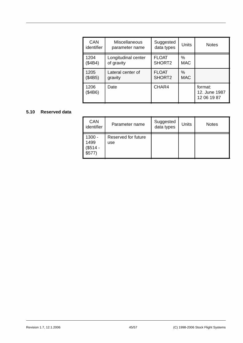
5.10 Reserved data
1204($4B4)
Longitudinal centerof gravity
FLOATSHORT2
%MAC
1205($4B5)
Lateral center ofgravity
FLOATSHORT2
%MAC
1206($4B6)
Date CHAR4 format:12. June 198712 06 19 87
CANidentifier
Parameter nameSuggesteddata types
Units Notes
1300 -1499($514 -$577)
Reserved for futureuse
CANidentifier
Miscellaneousparameter name
Suggesteddata types
Units Notes
45/57 (C) 1998-2006 Stock Flight Systems

Revision 1.7, 12.1.2006
6.1 Baseline system
6 Time-Triggered Bus Scheduling
This section describes a sample avionics system for a general aviationaircraft and the resulting CANaerospace bus implementation.
The purpose of this example is to serve as a guideline for the evaluati-on of system requirements, CANaerospace bus load and transmissionrates based on the basic systems installed in modern technology ge-neral aviation aircraft.
The baseline system reflects the avionic system as installed in a IFR-equipped single engine general aviation aircraft using flat panel prima-ry flight and navigation displays. This architecture was chosen as itcan potentially support “highway in the sky” (HITS) technology. Eventhough it was kept rather simple, however, to better serve its purposeas explanatory example:
To determine the CANaerospace bus schedule, it will be assumed thatthe maximum transfer rate of parameters is 80Hz (12.5ms). We couldtransmit data at a much higher rate but this would make no sense un-less there is equipment installed which can make use of this.
CANaerospaceNode-ID
System Description
1 Attitude/heading reference system (AHRS)
2 Air data computer (ADC)
3 VHF communication transceiver #1
4 VHF communication transceiver #2
5 NAV/ILS/Marker receiver #1
6 NAV/ILS/Marker receiver #2
7 ATC transponder
8 ADF receiver
9 GPS receiver
10 Distance measuring equipment (DME)
11 Engine monitoring system (EMS)
12 Electrical trim system
13 Electric system
46/57 (C) 1998-2006 Stock Flight Systems

Revision 1.7, 12.1.2006
6.2 The transmissionslot concept
The concept of the time-triggered bus scheduling uses a “minor timeframe” (12.5ms in our case) and takes advantage of the fact that notall messages in a given system have to be transmitted at this interval.Specifying multiples of the minor time frame transmission interval andassociated “transmission slots” allow a substantially larger number ofparameters to be transmitted on a single bus:
With this transmission slot concept, either 100 parameters transmittedeach 12.5ms or 8000 parameters transmitted once a second wouldgenerate 100% bus load. More likely, however, a combination of para-meters in the various transmission slot groups from this table (A-G)will be used. For our baseline system, we identified the following dataand assigned them the transmission slot groups A,D and G:
Transmissioninterval
Parameters/Transmission
Slot
Number ofTransmission
Slots (equalling100% bus load)
TransmissionSlot
Identification
12.5ms(80Hz)
1 100 A0 - A99
25ms(40Hz)
2 200 B0[0] - B99[1]
50ms(20Hz)
4 400 C0[0] - C99[3]
100ms(10Hz)
8 800 D0[0] - D99[7]
200ms(50Hz)
16 1600 E0[0] - E99[15]
400ms(2.5Hz)
32 3200 F0[0] - F99[31]
1000ms(1.0Hz)
80 8000 G0[0] - G99[79]
TxSlot
Parameter Name UnitTrans-
missionInterval
CAN-IDDataType
A0 Body longitudinalacceleration
g 12.5ms 300($12C)
FLOAT
A1 Body lateralacceleration
g 12.5ms 301($12D)
FLOAT
47/57 (C) 1998-2006 Stock Flight Systems

Revision 1.7, 12.1.2006
A2 Body normalacceleration
g 12.5ms 302($12E)
FLOAT
A3 Body pitch rate deg/s 12.5ms 303($12F)
FLOAT
A4 Body roll rate deg/s 12.5ms 304($130)
FLOAT
A5 Body yaw rate deg/s 12.5ms 305($131)
FLOAT
A6 Body pitch angle deg 12.5ms 311($137)
FLOAT
A7 Body roll angle deg 12.5ms 312($138)
FLOAT
A8 Heading angle deg 12.5ms 321($141)
FLOAT
D0[0] Altitude rate m/s 100ms 314($13A)
FLOAT
D0[1] True airspeed m/s 100ms 316($13C)
FLOAT
D0[2] Computed (calibrated)airspeed
m/s 100ms 317($13D)
FLOAT
D0[3] Baro correction hPa 100ms 319($13F)
FLOAT
D0[4] Baro corrected altitude m 100ms 320($140)
FLOAT
D0[5] Standard altitude m 100ms 322($142)
FLOAT
D0[6] Lateral stick trim posi-tion command
% 100ms 402($192)
FLOAT
D0[7] Longitudinal stick trimposition command
% 100ms 405($195)
FLOAT
D1[0] Engine RPM 1/min 100ms 500($1F4)
FLOAT
D1[1] Propeller RPM 1/min 100ms 504($1F8)
FLOAT
D1[2] Engine exhaust gastemperature (EGT)
K 100ms 520($208)
FLOAT
D1[3] Engine fuel flow rate l/h 100ms 524($20C)
FLOAT
TxSlot
Parameter Name UnitTrans-
missionInterval
CAN-IDDataType
48/57 (C) 1998-2006 Stock Flight Systems

Revision 1.7, 12.1.2006
D1[4] Engine manifoldpressure
hPa 100ms 528($210)
FLOAT
D1[5] Engine oilpressure
hPa 100ms 532($214)
FLOAT
D1[6] Engine oiltemperature
K 100ms 536($218)
FLOAT
D1[7] Engine cylinder headtemperature (CHT)
K 100ms 540($21C)
FLOAT
D2[0] Fuel tank #1 quantity kg 100ms 668($29C)
FLOAT
D2[1] Fuel tank #2 quantity kg 100ms 669($29D)
FLOAT
D2[2] Fuel system pressure hPa 100ms 684($2AC)
FLOAT
D2[3] DC voltage V 100ms 920($398)
FLOAT
D2[4] DC current A 100ms 930($3A2)
FLOAT
D2[5] GPS height aboveellipsoid
m 100ms 1030($40E)
FLOAT
D2[6] GPS aircraft latitude deg 100ms 1036($40c)
FLOAT
D2[7] GPS aircraft longitude deg 100ms 1037($40D)
FLOAT
D3[0] GPS ground speed m/s 100ms 1039($40F)
FLOAT
D3[1] GPS true track deg 100ms 1040($410)
FLOAT
D3[2] DME distance m 100ms 1071($42F)
FLOAT
D3[3] DME time-to-station min 100ms 1075($433)
FLOAT
D3[4] DME ground speed m/s 100ms 1079($437)
FLOAT
D3[5] ILS #1 localizer devia-tion
deg 100ms 1087($43F)
FLOAT
D3[6] ILS #2 localizer devia-tion
deg 100ms 1088($440)
FLOAT
TxSlot
Parameter Name UnitTrans-
missionInterval
CAN-IDDataType
49/57 (C) 1998-2006 Stock Flight Systems

Revision 1.7, 12.1.2006
A transmission interval of “1s/event” means that the respective para-meter is transmitted once upon every state change and additionallyonce a second if the state is unchanged.
Analyzing the “Tx Slot” fields, we find out that our baseline system re-quires 9 parameters to be transmitted each 12.5ms, 32 parameters tobe transmitted each 100ms and 10 parameters to be transmitted oncea second. This results in the following transmission slot allocation:
D3[7] ILS #1 glideslopedeviation
deg 100ms 1091($443)
FLOAT
D4[0] ILS #2 glideslopedeviation
deg 100ms 1092($444)
FLOAT
D4[1] VOR #1 radial deg 100ms 1126($466)
FLOAT
D4[2] VOR #2 radial deg 100ms 1127($467)
FLOAT
D4[3] ADF #1 relative bear-ing
deg 100ms 1083($43B)
FLOAT
G0[0] Static air temperature K 1s 324($144)
FLOAT
G0[1] Trim system switches 1sevent
439($1B7)
BSHORT
G0[2] Trim system lights 1sevent
440($1B8)
BSHORT
G0[3] Engine status 1sevent
556($22C)
BSHORT
G0[4] VHF COM #1 fre-quency
MHz 1sevent
1100($44B)
FLOAT
G0[5] VHF COM #2 fre-quency
MHz 1sevent
1101($44C)
FLOAT
G0[6] Transponder #1 code BCD 1sevent
1116($45C)
FLOAT
G0[7] ADF #1 frequency kHz 1sevent
1108($454)
FLOAT
G0[8] VOR/ILS #1 frequency MHz 1sevent
1104($450)
FLOAT
G0[9] VOR/ILS #2 frequency MHz 1sevent
1105($451)
FLOAT
TxSlot
Parameter Name UnitTrans-
missionInterval
CAN-IDDataType
50/57 (C) 1998-2006 Stock Flight Systems

Revision 1.7, 12.1.2006
51/57(C
) 1998-2006 Stock F
light System
s
A0 A1 A2 A3 A4
9 variable
variables transmitte
minor time
subsequent minor t
transmitteeach 12.5
D1A5 A6 A7 A8 D0 D2 D3 G0
s 8 parameters transmitted each 100ms8 parameters transmitted each 100ms8 parameters transmitted each 100ms8 parameters transmitted each 100ms64 parameters transmitted each 1s
minor time frame (n)
minor time frame (n+2)
minor time frame (n+3)
minor time frame (n+1)
d in
frame 12.5ms
D0[0]
imeframes
dms
D0[1]
D0[2]
D0[3]
D0[4]
D0[5]
D0[6]
D0[7]
D1[0]
D1[1]
D1[2]
D1[3]
D1[4]
D1[5]
D1[6]
D1[7]
minor time frame (n+4)
minor time frame (n+5)
minor time frame (n+6)
minor time frame (n+7)
D2[0]
D2[1]
D2[2]
D2[3]
D2[4]
D2[5]
D2[6]
D2[7]
D3[0]
D3[1]
D3[2]
D3[3]
D3[4]
D3[5]
D3[6]
D3[7]
G0[0]
G0[1]
G0[2]
G0[3]
G0[4]
G0[5]
G0[6]
G0[7]
G0[8] minor time frame (n+8)D0[0] D1[0] D2[0] D3[0]
. . . . .. . . . .

Revision 1.7, 12.1.2006
6.3 Bus load compu-tation
1111
start of frame
message id
interframe space (>= 3
The CAN bus data frame (11-bit identifier) has the following outline:
Most CANaerospace messages use all 8 bytes of the data field whichresults in a message length of 44bits + 64bits = 108bits. To computethe maximum bus capacity, we have to add the interframe space(3bits) and a number of stuff bits (a maximum of 18 additional bits, weassume an average of 14) which gives a message length of 108bits +3bits + 14bits = 125bits. Assuming the maximum data transfer rate of1Mbit/s, a CANaerospace message takes 125µs to transmit. Hence,the CANaerospace bus capacity is 8.000 messages/second.
Defining a minor time frame of 12.5ms (80Hz) results in 100 parame-ters which can be transmitted during this interval. This number can beconsidered 100% bus load:
CANaerospace message time: 125µsSelected minor time frame: 12.5ms100% bus load: 12.5ms/125µs = 100 messages
For 29-bit identifier CAN messages (CAN 2.0B), the message time is145µs, which results in 16% less bus capacity than for 11-bit identifierCAN messages. If both 11-bit and 29-bit messages are used at thesame time, the calculation should be done for each identifier type se-perately and combined afterwards to assemble the resulting bus sche-dule data.
Our baseline system uses the following parameter/transmission inter-val matrix:
Byte 4 Byte 5 Byte 6 Byte 7Byte 0 Byte 1 Byte 2 Byte 3
Message Header
The CAN bus data frame (11-bit identifier) has the following outline:
Most CANaerospace messages use all 8 bytes of the data field whichresults in a message length of 44bits + 64bits = 108bits. To computethe maximum bus capacity, we have to add the interframe space(3bits) and a number of stuff bits (a maximum of 18 additional bits, weassume an average of 14) which gives a message length of 108bits +3bits + 14bits = 125bits. Assuming the maximum data transfer rate of1Mbit/s, a CANaerospace message takes 125µs to transmit. Hence,the CANaerospace bus capacity is 8.000 messages/second.
Defining a minor time frame of 12.5ms (80Hz) results in 100 parame-ters which can be transmitted during this interval. This number can beconsidered 100% bus load:
CANaerospace message time: 125µsSelected minor time frame: 12.5ms100% bus load: 12.5ms/125µs = 100 messages
For 29-bit identifier CAN messages (CAN 2.0B), the message time is145µs, which results in 16% less bus capacity than for 11-bit identifierCAN messages. If both 11-bit and 29-bit messages are used at thesame time, the calculation should be done for each identifier type se-perately and combined afterwards to assemble the resulting bus sche-dule data.
Our baseline system uses the following parameter/transmission inter-val matrix:
data frame (44 + 0 ... 64 bit)
6 15 71 1 1
entifier
CRC delimiter
CRC sequence field
data field (0 ... 8 data bytes)
control field (number of data bytes)
RTR (remote transmission request) bit
end of frame
ACK delimiter
ACK slot
bits)
52/57 (C) 1998-2006 Stock Flight Systems

Revision 1.7, 12.1.2006
7.1 Redundant mes-sage identifierassignment
As the baseline system uses 13.625 out of 100 available transmissionslots, the corresponding CANaerospace bus load is:
13.625%
Keeping in mind that asynchronous event data or node service datamight require additional bus capacity, we should leave some marginfor this (around 20%). Therefore, our system should not continouslyexceed 80% bus load. Even though, this analysis shows that CANae-rospace offers adequate growth capability for general aviation aircraftavionics.
7 System redundancy support
The probability of an undetected data corruption in a CAN network isaround 1 * 10-13 per message transmission. Assuming 100% bus load(around 8.000 messages per second), this will result in a probability of2.9 * 10-6 undetected failures per flight hour, making CANaerospace acandidate for mission and flight critical systems.
While this figure is better than for any other bus system available to-day, it shows that a single CANaerospace bus (like all other buses) willmost likely not be adequate for flight critical systems, especially forthose requiring fail-operational behaviour. For those applications, sy-stem redundancy is inevitable to demonstrate a required level offunctional safety.
A system architecture as used by many modern integrated avionicsand electronic flight control systems is shown below. In this architecu-re, two redundant units of the same type communicate via an equalnumber of communication channels. Proper design provided, this sy-stem will prevent a single failure to cause a complete loss of function:
Transmissioninterval
ParametersRequired
TransmissionSlots
Parameters/Transmission Slot
12.5ms 9 9 1
100ms 36 5 (4.5) 8 (0.1s/12.5*10-3s)
1s 10 1 (0.125) 80 (1s/12.5*10-3s)
total 55 15 (13.625)
53/57 (C) 1998-2006 Stock Flight Systems
AHRS 1 AHRS 2 ADC 1 ADC 2 FCC 1 FCC 2
Bus 1
Bus 2

Revision 1.7, 12.1.2006
7.2 System redun-dancy and theCANaerospaceheader
Using the standard identifier distribution, each CANaerospace databus parameter has assigned a single, unique identifier (i.e. 304 forbody roll rate). This means that only one unit would be allowed totransmit a particular parameter on the bus. A redundant system archi-tecture as described is supported by CANaerospace, however, if the29-bit identifiers are used. In this case, a “redundancy level offset” inmultiples of 65536 ($10000) is added to each identifier so that thesame parameter can be transmitted by several units using multipleunique identifiers:
Unlike other buses like ARINC429, ARINC629 or MIL-STD-1553B,CANaerospace is a dynamic network with a bus schedule that varieswithin certain limits. Certification in flight safety critical applications,however, requires to demonstrate the proper function of the data trans-mission under all conditions. Monitoring CANaerospace messagesduring normal operation and processing the header information deli-vers the required information for certification. Additionally, the headerinformation improves flexibility and supports dynamic network reconfi-guration. Power down/up situations are handled gracefully, units maybe added to the network without software changes. Taking advantageof the header information, CANaerospace bus analyzers and simula-tors can be inserted even into a running network and will immediatelyhave all information about network structure, units and data. This en-sures fast and cost-effective maintenance:
• Node-ID (Byte 0): Some system architectures employ backupunits which become active if the main unit fails. The Node-IDallows to immediately identify this situation and react accor-dingly (i.e. mode change within redundancy management).
• Data Type (Byte 1): CANaerospace supports multiple data ty-
RedundancyChannel #
RedundancyLevel Offset
Example: BodyRoll Rate ID
(decimal)
Example: BodyRoll Rate ID
(hexadecimal)
0 0 304 $130
1 65536 65840 $10130
2 131072 131376 $20130
3 196608 196912 $30130
n 65536 * n 65536 * n + 304 $[10*n]130
Byte 4 Byte 5 Byte 6 Byte 7Byte 0 Byte 1 Byte 2 Byte 3
Message Header
54/57 (C) 1998-2006 Stock Flight Systems
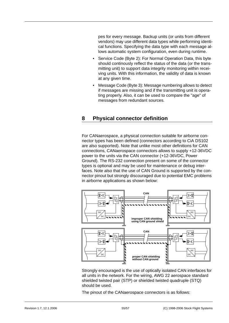
Revision 1.7, 12.1.2006
pes for every message. Backup units (or units from differentvendors) may use different data types while performing identi-cal functions. Specifying the data type with each message al-lows automatic system configuration, even during runtime.
• Service Code (Byte 2): For Normal Operation Data, this byteshould continously reflect the status of the data (or the trans-mitting unit) to support data integrity monitoring within recei-ving units. With this information, the validity of data is knownat any given time.
• Message Code (Byte 3): Message numbering allows to detectif messages are missing and if the transmitting unit is opera-ting properly. Also, it can be used to compare the "age" ofmessages from redundant sources.
8 Physical connector definition
For CANaerospace, a physical connection suitable for airborne con-nector types has been defined (connectors according to CiA DS102are also supported). Note that unlike most other definitions for CANconnections, CANaerospace connectors allows to supply +12-36VDCpower to the units via the CAN connector (+12-36VDC, PowerGround). The RS-232 connection present on some of the connectortypes is optional and may be used for maintenance or debug inter-faces. Note also that the use of CAN Ground is supported by the con-nector pinout but strongly discouraged due to potential EMC problemsin airborne applications as shown below:
Strongly encouraged is the use of optically isolated CAN interfaces forall units in the network. For the wiring, AWG 22 aerospace standardshielded twisted pair (STP) or shielded twisted quadruple (STQ)should be used.
The pinout of the CANaerospace connectors is as follows:
DC
DC
DC
DC
DC
DC
DC
DC
CAN
CAN
improper CAN shielding
proper CAN shielding
using CAN ground shield
without CAN ground
55/57 (C) 1998-2006 Stock Flight Systems

Revision 1.7, 12.1.2006
MIL-24308/8 connector (similar to CiA DS102)
MIL-C-26482 connector s MS3470L1006PN (wall mount recepta-cle) and MS3476L1006SN (mating straight plug)
Pin A Power GndPin B +12-36VDCPin C ShieldPin D CAN HighPin E CAN LowPin F CAN Gnd
MIL-C-38999 connector s D38999/20FB35PN (wall mount recepta-cle) and D38999/26FB35SN (mating straight plug)
Pin 1 +12-36VDC Pin 6 RS-232 RxDPin 2 CAN Low Pin 7 CAN HighPin 3 CAN Gnd Pin 8 ShieldPin 4 RS-232 TxD Pin 9 RS-232 GndPin 5 DC Gnd Pin 10-13 unused
6
7
8
9
1
2
3
4
5
RS-232 RxD
CAN High
Shield
RS-232 Gnd
Power +12-36VDC
CAN Low
CAN Ground
RS-232 TxD
Power Gnd
A
B
C
DE
F
4
3
2
1
6
5
7
8
9
1011
12 13
56/57 (C) 1998-2006 Stock Flight Systems

Revision 1.7, 12.1.2006
1 n
MIL-C-38999 connector D38999/20F A35PN (wall mount recepta-cle) and D38999/26FA35SN (mating straight plug)
Pin 1 +12-36VDC Pin 4 CAN HighPin 2 CAN Low Pin 5 DC GndPin 3 CAN Gnd Pin 6 Shield
A sample interconnection of multiple CANaerospace systems usingD38999/20FB35PN wall mount receptacles and D38999/26FB35SNstraight plugs is shown here:
Note: The RS-232 lines defined for this connector type are optionaland may be used for device programming, configuration, etc. Theyhave no relationship to CAN or CANaerospace.
CANaerospace systems requiring high reliability or life-insertion capa-bilities should be connected as shown below. The preferred CAN bustopology is a shielded, twisted pair single line, terminated at bothends. Units are connected via simple stubs within the connector.Using this method, removing a unit from the bus (or reattaching it) willnot adversely affect the others: The bus is not opened by unpluggingthe connectors:
1
4
3
26
5
Pinout Signal
Pin 1/B +12-36VDCPin 2/E CAN LowPin 3/F CAN GndPin 4 RS-232 TxDPin 5/A DC GndPin 6 RS-232 RxDPin 7/D CAN HighPin 8/C ShieldPin 9 RS-232 GndPin 10 +12-36VDCPin 11 DC GndPin 12 CAN LowPin 13 CAN High
shielded twistedpair or quadruple(CAN or CAN/power)
shielded twistedpair or quadruple(CAN or CAN/power)
CAN High
CAN Low
Unit 1 Unit 2 Unit 3 Unit 4 Unit n-1 Unit n
20Ω termination 120Ω terminatiostub withinconnector
57/57 (C) 1998-2006 Stock Flight Systems