naomi wfs ccd camera controldocs/wht/naomi/wht-naomi-1/wht-naomi-1.pdfthe wfs system has two ccd...
TRANSCRIPT

Royal Observatory, Edinburgh Blackford Hill Edinburgh, EH9 3HJ United Kingdom Telephone: +44 (0)131 668 8100 Facsimile: 668 8264 (Central)
662 1668 (West Wing) 668 1130 (Villas) 662 1654 (Directorate)
Email: [email protected] WWW: http://www.roe.ac.uk/
UK
Astronomy Technology Centre
NAOMI WFS CCD CAMERA CONTROL Derek Ives wht-naomi-1
Version 3 - 7/1/2000

1. Introduction
The following notes give a brief description of the readout modes which have been implemented in the CCD Camera system used in the NAOMI WFS. It also gives a detailed description of the commands required to execute these different readout modes.
The system implemented in NAOMI consists of two CCD camera systems, a VME control system and an array of C40 DSPs (ELECTRA to be built in Durham). The image data is fed from the CCD cameras directly to the ELECTRA system, by-passing the VME bus in the WFS VME control System. The ELECTRA system then performs the image centroiding calculations. Appendix A shows the image and control paths for the WFS system. A system has also been implemented where the image data can be sent across the VME bus, then via a LAN to a display system such as SAOTNG. This has been implemented for test purposes at the ATC; the frame rate will be much lower for the VME implementation than for the C40 implementation.
The two CCD cameras in the system can be operated in a MASTER and SLAVE mode where one camera is designated the MASTER and the other the SLAVE. They read out together synchronously with the MASTER supplying the Master clock and control signals to both the Master and Slave cameras. They can also be readout in a SINGLE CAMERA mode where either or both the MASTER or the SLAVE are readout but they are not synchronised. If both cameras are run asynchronously then there may be severe problems with clock cross talk and increased noise. This two camera concept was implemented to increase system throughput.
The CCDs are themselves also electronically divided into apertures in which some pixels are skipped over and dumped and others are read out. This again has been done to increase system throughput. These apertures are fixed on the CCD, that is their X-start, Y-start and X and Y sizes are fixed in the system software and never change. The CCDs are also binned, depending on the readout mode selected. Figure 1 shows one quadrant of the CCD and how it is sub-divided into these apertures. Each CCD consists of four such quadrants, divided as shown.
40 pixels
40 pixels
8 x 8 pixels per Aperture Figure 1 - CCD Quadrant (4 per CCD)
5 x 5 Apertures per quadrant
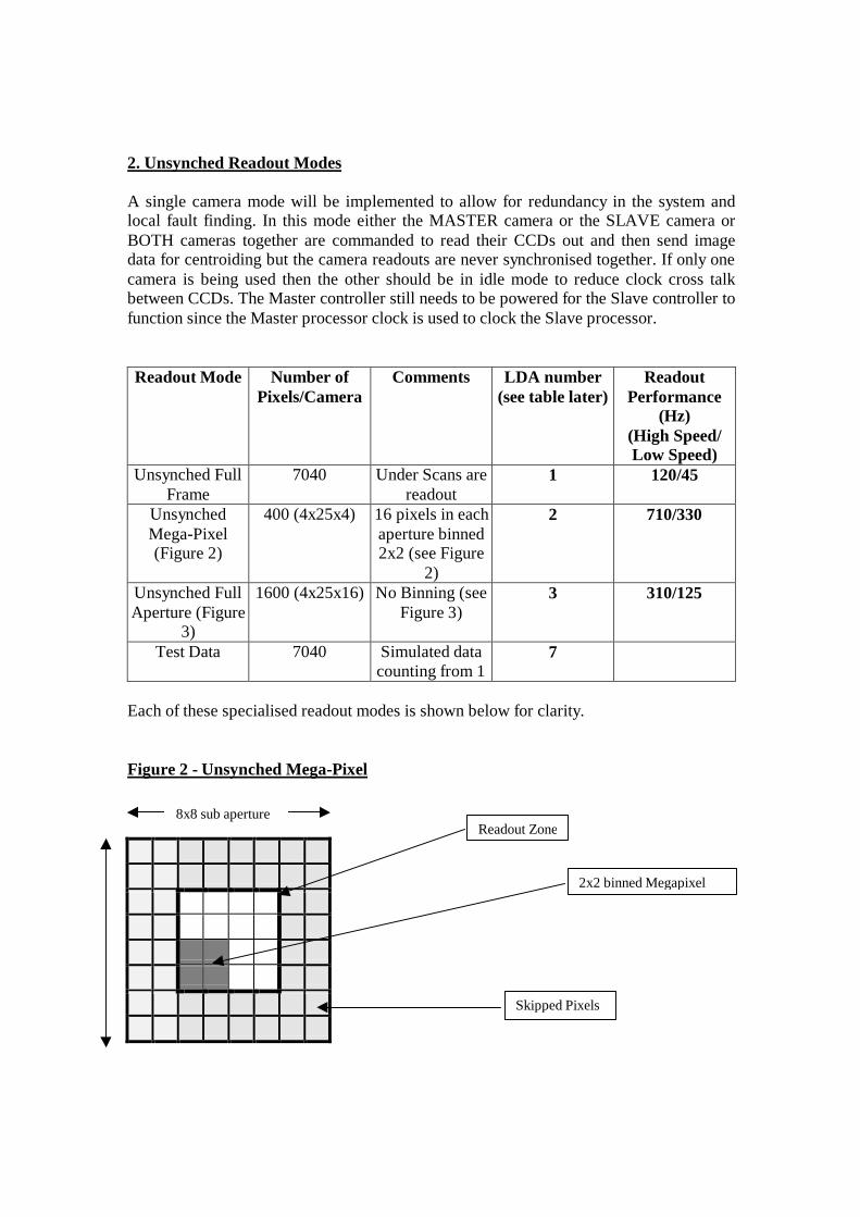
2. Unsynched Readout Modes A single camera mode will be implemented to allow for redundancy in the system and local fault finding. In this mode either the MASTER camera or the SLAVE camera or BOTH cameras together are commanded to read their CCDs out and then send image data for centroiding but the camera readouts are never synchronised together. If only one camera is being used then the other should be in idle mode to reduce clock cross talk between CCDs. The Master controller still needs to be powered for the Slave controller to function since the Master processor clock is used to clock the Slave processor. Readout Mode Number of
Pixels/Camera Comments LDA number
(see table later) Readout
Performance (Hz)
(High Speed/ Low Speed)
Unsynched Full Frame
7040 Under Scans are readout
1 120/45
Unsynched Mega-Pixel (Figure 2)
400 (4x25x4) 16 pixels in each aperture binned 2x2 (see Figure
2)
2 710/330
Unsynched Full Aperture (Figure
3)
1600 (4x25x16) No Binning (see Figure 3)
3 310/125
Test Data 7040 Simulated data counting from 1
7
Each of these specialised readout modes is shown below for clarity. Figure 2 - Unsynched Mega-Pixel
8x8 sub aperture Readout Zone
2x2 binned Megapixel
Skipped Pixels
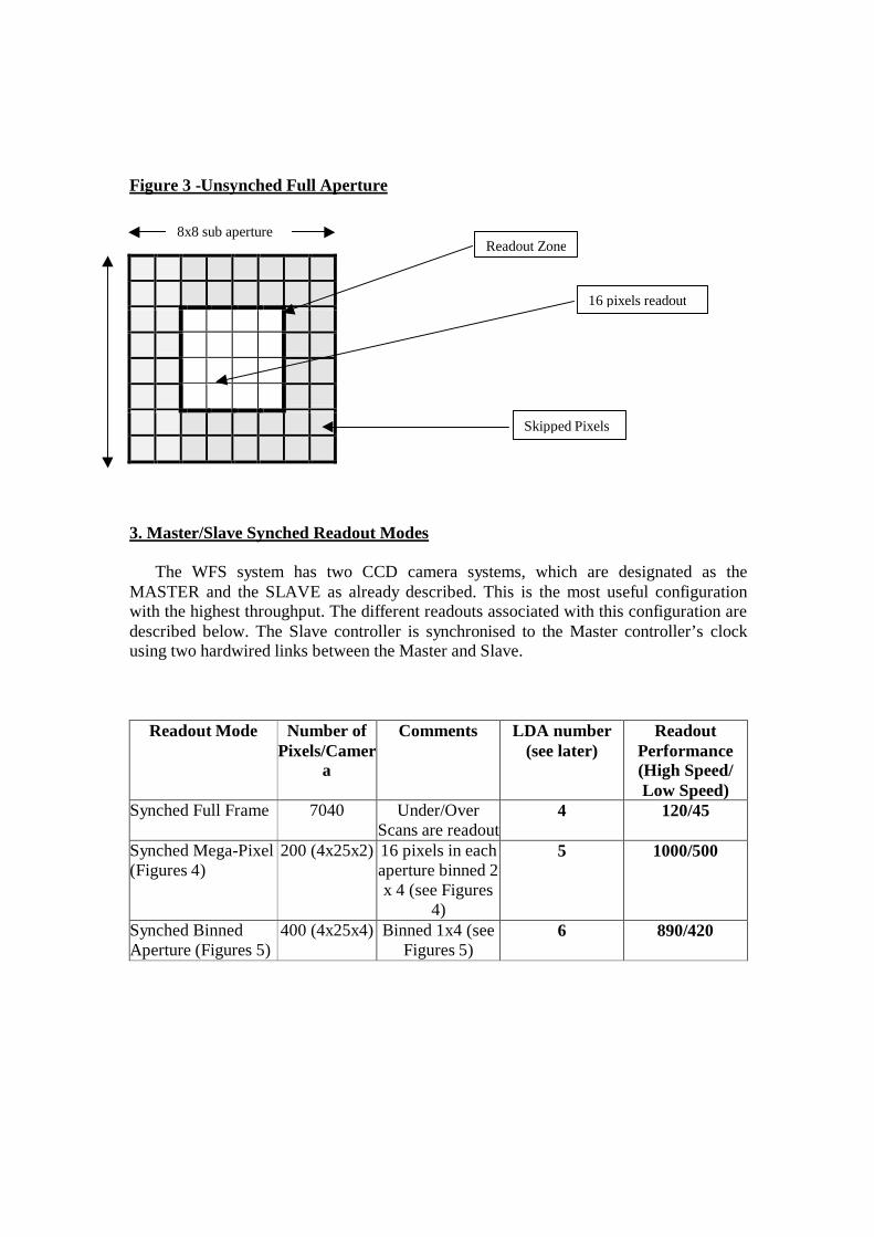
Figure 3 -Unsynched Full Aperture
3. Master/Slave Synched Readout Modes
The WFS system has two CCD camera systems, which are designated as the MASTER and the SLAVE as already described. This is the most useful configuration with the highest throughput. The different readouts associated with this configuration are described below. The Slave controller is synchronised to the Master controller’s clock using two hardwired links between the Master and Slave.
Readout Mode Number of Pixels/Camer
a
Comments LDA number (see later)
Readout Performance (High Speed/ Low Speed)
Synched Full Frame 7040 Under/Over Scans are readout
4 120/45
Synched Mega-Pixel (Figures 4)
200 (4x25x2) 16 pixels in each aperture binned 2 x 4 (see Figures
4)
5 1000/500
Synched Binned Aperture (Figures 5)
400 (4x25x4) Binned 1x4 (see Figures 5)
6 890/420
8x8 sub aperture
16 pixels readout
Skipped Pixels
Readout Zone

Figure 4 – Synched Slave Mega-Pixel
Figure 5 – Synched Slave Binned Aperture 4. SDSU Controller Software Design Philosophy
The same boot code software will be used to run on both the Master and the Slave controllers. Different Application code will be running on the Master and Slave controllers but this will have been derived from the same source. The differences are mainly due to flags being set to indicate to the ELECTRA system which is a Master and which is a Slave. A Master or Slave assembly time switch will be set to determine for which system the code will be used.
2x4 binned Megapixel
Skipped Pixels
Readout Zone 8x8 pixels per aperture
Y
8x8 sub aperture
4 pixels binned vertically
Skipped Pixels
Readout Zone
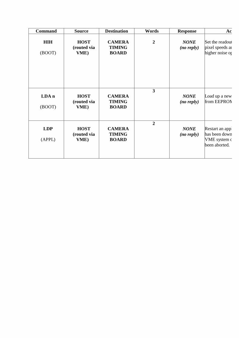
At present there are seven different readout modes to be implemented as already described above. My design approach will be to produce highly optimised code for each readout mode. When a new readout mode is selected then a new piece of application code is loaded into the SDSU controllers' internal memory and executed. This is instead of having one large program which offers all readout modes and which is running all the time. The advantage of this approach is that highly optimised code can be written for each readout mode. It also allows the system to change to a new readout mode in the minimum of time, typically very much less than 1 ms. There is also only a very small on-board address space and it will be easier to fit small optimised programs into this address space. This approach should also offer best noise and readout speed performance. Each application will be stored in on board EEPROM memory. When required it will be read from EEPROM into on-board DSP memory and then executed. Separate applications can also be run to allow built in test functions or to allow testing of the clocks etc. We still offer the option of also being able to download new application programs from the fibre link. The disadvantage of this is that it will take very much longer to download. Also the controller will have to be commanded to abort its present operation before the download takes place. It will then have to be commanded to execute the new downloaded code. This is different to when the code is internally downloaded from the on board EEPROM when auto execution of the new program occurs. 5. SDSU Controller Commands The commands required to operate the NAOMI CCD camera systems are described in the following table. Commands to the SDSU controllers can only be made via the VME system. Likewise, replies to commands can only be seen via the VME system. However image data with associated header information is directed to the ELECTRA system, without going onto the VME backplane. This data path is made via a front panel parallel ribbon cable link to a RS422 module and thence to the ELECTRA. In terms of the commands themselves, each command consists of 2,3 or 4 of 24 bit words. “BOOT” commands are available on power-up or reset. "APPL" commands after an application has been downloaded. Commands sourced as HOST come from the VxWorks operating system or some higher level system such as ELECTRA.
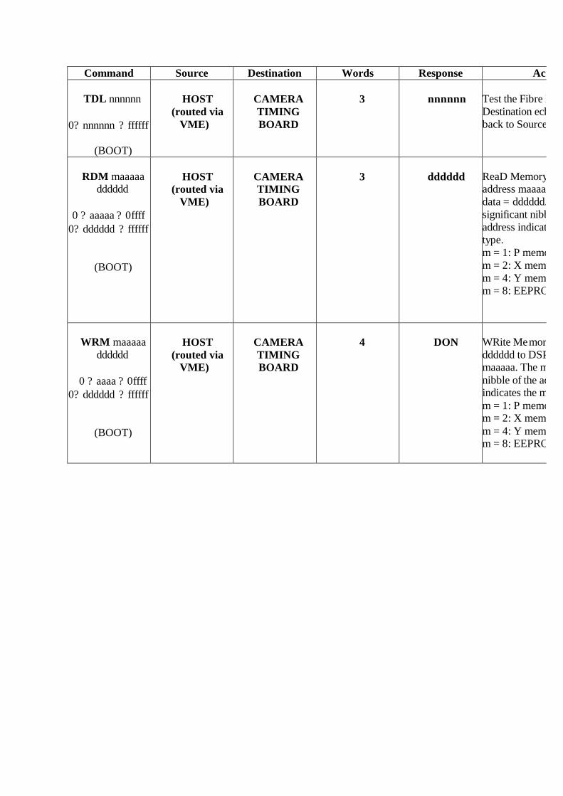
Command Source Destination Words Response Action
TDL nnnnnn
0? nnnnnn ? ffffff
(BOOT)
HOST
(routed via VME)
CAMERA TIMING BOARD
3
nnnnnn
Test the Fibre Data LDestination echoes nnnnnn back to Source.
RDM maaaaa
dddddd
0 ? aaaaa ? 0ffff 0? dddddd ? ffffff
(BOOT)
HOST
(routed via VME)
CAMERA TIMING BOARD
3
dddddd
ReaD Memory. Read DSP address maaaaa. Returned data = dddddd. The most significant nibble of the address indicates the memory type. m = 1: P memorym = 2: X memorym = 4: Y memorym = 8: EEPROM
WRM maaaaa
dddddd
0 ? aaaa ? 0ffff 0? dddddd ? ffffff
(BOOT)
HOST
(routed via VME)
CAMERA TIMING BOARD
4
DON
WRite Memory. Write dddddd to DSP address maaaaa. The most significant nibble of the address indicates the memory type.m = 1: P memorym = 2: X memorym = 4: Y memorym = 8: EEPROM

Command Source Destination Words Response Action
CHK
(BOOT)
HOST
(routed via VME)
CAMERA TIMING BOARD
2
xxxxxx
Checksum Timimemory areas where xxxxxx is calculated checksum value.
SYC H L
H is top 14 bits of synched frame counter L is lower 14 bits of frame counter
(BOOT)
HOST
(routed via VME)
CAMERA TIMING BOARD
4
NONE
(no reply)
This command is used to execute a previously received command such as HIH,SLW,SET or LDA. The new command is implemented on the specified frame counter.If H=L=0 then the action occurs immediately.
PON
(BOOT)
HOST
(routed via VME)
CAMERA TIMING BOARD
2
DON
This command causes the SDSU to apply the voltages to the CCD in a controlled manner - use at start up.
POF
(BOOT)
HOST
(routed via VME)
CAMERA TIMING BOARD
2
DON
This comma nd causes the SDSU to disable the voltages to the CCD - use at end.

Command Source Destination Words Response Action
SET nnnnnn
(BOOT)
HOST
(routed via VME)
CAMERA TIMING BOARD
2
NONE
(no reply)
Change integration time to nnnnnn where each unit is 25us. Integration time can therefore be set between 0
ABT
(BOOT)
HOST
(routed via VME)
CAMERA TIMING BOARD
3
DON
Abort execution of present application
SLW
(BOOT)
HOST
(routed via VME)
CAMERA TIMING BOARD
2
NONE
(no reply)
Set the readout rate to slow pixel speeds and low noise operation.
Command Source Destination Words Response Action
HIH
(BOOT)
HOST
(routed via VME)
CAMERA TIMING BOARD
2
NONE
(no reply)
Set the readout rate to high pixel speeds and therefore higher noise operation
LDA n
(BOOT)
HOST
(routed via VME)
CAMERA TIMING BOARD
3 NONE
(no reply)
Load up a new application n from EEPROM
LDP
(APPL)
HOST
(routed via VME)
CAMERA TIMING BOARD
2 NONE
(no reply)
Restart an application after it has been down loaded from VME system or after it has been aborted.

Command Source Destination Words Response Action
SYR (BOOT)
CAMERA TIMING BOARD
HOST (routed via
VME)
2 NONE (is a response)
Response from SDSU control after a power up, system reset or reboot sequence.
DON (BOOT)
CAMERA TIMING BOARD
HOST (routed via
VME)
2 NONE (is a response)
Usual response to most commands
ERR (BOOT)
CAMERA TIMING BOARD
HOST (routed via
VME)
2 NONE (is a response)
Response to an incorrect Word 2 received
WHR (BOOT)
CAMERA TIMING BOARD
HOST (routed via
VME)
NONE (is a response)
Response to an incorrect Word 1 received
6 VME System Commands
The commands required to operate the NAOMI VME system are described in the following table. Commands tomade via the Host, that is, over the network from ELECTRA etc. Likewise replies to commands can only be seen via the Host system. However image data with associated header information can be directed to the VME system which then feeds this data via a QI server to a display tool such as SAOTNG running on a UNIX station. The display tool only displays images at the rate of a few Hertz. This is very useful for set up and test purposes only.

Command Source Destination Words Response ActionLDA n
(BOOT)
HOST VME 3 DON Load application program from EEPROM into the VME memory area.
RDM Maaaaa
(BOOT)
HOST VME 3 Dddddd
ReaD Memory. Read Daddress maaaaadata = dddddd. The most significant nibble of the address indicates the memory type. m = 1: P memory memory m = 4: Y memory EEPROM
WRM maaaaa dddddd
(BOOT)
HOST VME
4 DON
Write Memory. Write dddddd to DSP address maaaaa. The most significant nibble of the address indicates the memory type. See RDM
TDL Nnnnnn
(BOOT)
HOST VME 3 Nnnnnn Test Data Link. Destination DSP echoes nnnnnnsource.
SRA hiaddr loaddr
(BOOT)
HOST VME 4 DON Set Reply Address. Defines the start of a circular buffer in VME memory that receives replies from the VME interface DSP.

Command Source Destination Words Response ActionRRS
(APPL)
HOST VME 2 SYR (fromTiming)
Remote Reset System. Reset the Timing DSP.
ABT
(APPL)
HOST VME 2 DON (from VME)
AborT. Abort the previous RDC/RDS command.
RDC
(APPL)
HOST VME
2 DON (from VME)
ReaD CCD. Put the VME DSP board in readout mode using the current readout sequence and loaded parameters. Waits for data frame from camera controller.
RDS
(APPL)
HOST VME 2 DON (from VME)
Same as RDC but data sent out to C40 through
FBA Aaaa,bbbb
(APPL)
HOST VME 4 Aaaa,bbbb=Frame buffer address
CHK
(BOOT)
HOST
VME
2
xxxxxx
Checksum VME board memory areas where xxxxxx is calculated check

Image Data Format A header packet and footer packet are also transmitted by the SDSU controllers to the VME system and hence ELEpacket. These packets are used to inform the higher level system of key information about the image type etc. This header and footer are described below. Header Packet This packet consists of 10 x 16 bit words which are transmit ted just before each frame of data is transmitted. The top 2 bits of each word are not used and do not have any significance, only the bottom 14 bits of each word are used. This is because most the header words with the data words are retransmitted by the VME board to the C40 link and the link to the C40 is only 14 bits wide. These words are described in the table below. Footer Packet The image data then follows these first 10 x 16 bit words and is also in 16 bit format. The controller then sends out a ftransmitting the image data. The footer consists of one 16 bit word set to the value 00. Notes :- ?? In the NAOMI - ELECTRA implementation, the image data is fed direct from the SDSU VME card via a ribbon cable to an ELECTRA i
card which uses RS422 logic to allow it to drive long cable runs. This card only transmits the lower 14 bits of each 16 bit word. ?? Note also that some words are stripped off the header packet before being transmitted to the ELECTRA system. These w
NAOMI usage only. Word 1, Word 2 and Word 3 are sent from the SDSU Timing board to the VME board to allow it to determine a start of frame. They are stripped off the header by the VME board and are NOT re -transmitted by the VME to thewhich is also set to 000000 is stripped off and not transmitted to the C40 system.

Word Number Name Value
1 Start of Frame Word 1 0000 (not seen by ELECTRA)
2 Start of Frame Word 2 0000 (not seen by ELECTRA) 3 Operation Mode Bit 1 to Bit 14 set
(not seen by ELECTRA) 4 Operation Mode
5 Frame Counter High Word
0 - 3FFF (top 14 bits)
6 Frame Counter Low Word 0 - 3FFF (bottom 14 bits)
7 Integration Time High Word 0 - 03FF
8 Integration Time Low Word 0 - 3FFF
9 Number of Pixels readout in a complete ROW of the CCD (note per CCD not per quadrant)
1 - 1000
10 Number of pixels readout in a complete COLUMN of the CCD (note per CCD not per quadrant)
1 - 1000

Operation Mode bits set significance (Bits 0, the LSB to Bits 14, the MSB) Bit 0 set - SET => Application 1 is running Bit 1 set - SET => Application 2 is running Bit 2 set - SET => Application 3 is running Bit 3 set - SET => Application 4 is running Bit 4 set - SET => Application 5 is running Bit 5 set - SET => Application 6 is running Bit 6 set - SET => Application 7 is running Bit 7 set - SET => A Downloaded Application is running (downloaded from fibre link as opposed to internal EEPROM)Bit 8 - SET => New Integration Timing, Readout Speed or Readout Mode has been requested, cleared on SYC executionBit 9 - SET => SYC command frame counter INVALID, counter already past this countBit 10 - unused Bit 11 - NOT SET => MASTER Controller SET => SLAVE Controller Bit 12 - NOT SET => NOT SYNCHRONISED - unsynched readout mode SET => SYNCHRONISED READOUT MODE - pulse seen from MASTER Bit 13 - NOT SET => SLOW speed is operational SET => HIGH speed is operational Example data stream from Timing Board to VME System Example - consider a Master controller, using synchronised readout, running application 6 at high speed (400 pixels of data per frame). It has an integration time of 5ms (200 units) and is already at frame number 1000000. It has received a new SET command bframe data would be the following (all hex format): - 0000 0000 3120 3120 00F1 0240 0000 00C8 0028 000A… .400 of 16 bit image data words… .0000 Data Stream from VME to C40 array 3120 00F1 0240 0000 00C8 0028 000A… .400 of 14 bi t image data words…

Command Sequences To control the NAOMI system correctly, which consists of a VME system and two CCD camera systems, requires that particular sequences of commands are sent to either the VME system or the SDSU camera controllers or both . However the ELECTRA system cannot communicate with the camera controller directly; its only link to the WFS system is via the LAN to the VME crate. However the VME system passes through all messages from the ELECTRA system to the SDSU controllers if the correct addresses have been specified. Startup Sequence At power on or system reset, the voltages to the CCDs are disabled for purposes of protection of the detector. These voltages must be switched on to the detector before valid images can be readout. The VME system must also be started up and the correct application got running before anything else can occur. Typically a startup script will be used to ensure that the WFS VME and SDSU cameras initialise as required. No other user interaction should be required for system initialisation. The startup script will also test the system functionality as much as is practically possible, for example, by using the TDL commands to test the data links to both VME and camera systems and by executing the CHK command to ensure that the correct boot code is running. The startup commands might be as follows: - 103 TDL xxxxxx - test VME communications link, xxxxxx is test data 102 CHK - check boot code installation, returns with checksum word 103 LDA 1 - load up applic ation 1 into VME memory, doesn't require SYC to execute 203 TDL xxxxxx - test SDSU MASTER camera communications link 202 CHK - check boot code installation 202 PON - switch voltages to CCD 203 LDA 1 - command load application 1 204 SYC 0 0 - execute LDA command - now reading out in application mode 1 repeat above sequence for SDSU SLAVE controller Synchronisation of both controllers Synchronisation is that mode of operation where both the Master and Slave controllers are able to integrate the sig nal and then readout the CCDs at the same time, to within a few tens of nanoseconds. This is achieved by feeding the 50 MHz Master DSP clock to both the DSP in the Master controller and also to the DSP in the Slave controller. A synchronisation pulse is al so fed from the Master controller to the Master DSP and also at the same time to the Slave DSP. This synchronisation pulse is sent out at the start of every frame. If synchronisation is functioning correctly then both controllers should be sending back the same frame counter at the start of each image data set sent to the ELECTRA system. The Master and Slave controllers will lose synchronisation if the controllers have different integration times as setup using the SET command or if they are running differe ntly in Slow or Fast readout mode. The higher level system must ensure that in the synchronised modes, the controllers use the same integration time and run at the same pixel speed.
Comments In the Synchronised modes, commands need still to be sent to both Master and Slave controllers. Having received a new mode command then the controllers will change from one readout mode to another and auto execute the new readout mode. However in the synchronised case the Slave controller would not auto run the new readout mode until it receives a synched pulse from the Master controller which has itself also auto executed the new code. The Master controller uses the same synch pulse to start itself. This then allows both controllers to readout in a synchronised state. The controllers will then continue to synchronise to each other at the start of every new frame. Some thought needs to be put into how the C40 system commands the camera systems to change readout modes and still ensure synchronisation. The command seque nce required to ensure this and other operation modes is also described in this document. Synchronise Master and Slave (Modes 4,5 and 6) - (previously unsynchronised) It is assumed that both cameras are already reading out in an unsynchronised mode. Command Slave to load up new synchronised Mode and await Master's start pulse. Commands to Slave :- 203 LDA n - command load application n (where n=4,5 or 6) Commands to Master :- 203 LDA n - command load application n is the same as above Commands to Slave :- 204 SYC 0 0 - execute LDA n command at once and await start pulse Slave controller now sits in a tight loop awaiting the start pulse from the Master. Commands to Master :- 204 SYC 0 0 - execute LDA n command and start. If both controllers have the same integration time and are running at the same pixel speed then they both will be synchronised from this point. The commands described above must take place in the order described above to ensure synchronisation. The above sequence of commands must also be used to synchronise the controllers only when the controllers were previously unsynchronised. Change from one synchronised mode to another and remain synchronised. This assumes that the controllers have previously been synchronised using the sequ ence of commands as described above. However if the system requires to change from one synchronised readout mode to another in a time of less than 1 millisecond and remain synchronised after this readout mode change then the following sequence of commands needs to be transmitted to the controllers. Again it must be emphasised that the commands must be sent in the order given here to ensure synchronisation. Commands to Slave :- 203 LDA n - command load application n (where n=4,5 or 6)
Commands to Master :- 203 LDA n - command load application n (where n=4,5 or 6) Commands to Slave :- 204 SYC H L - execute LDA n command at frame number H L and await start pulse Slave controller now sits in a tight loop awaiting the start pulse from the Master. Commands to Master :- 204 SYC H L - execute LDA n command at frame H L and start. where H is the frame counter high word and L is the frame counter low word The controllers will change over to the new synchronised readout mode on the frame counter number H and L given in the SYC command. The high level system must ensure that the SYC frame counter is greater than the present frame counter for each of the controllers. The easiest way to achieve this is to ensure the new counter would take at least 10 seconds to b e reached in the present readout mode of the controllers. This will then ensure that both controllers will have received the new LDA and SYC commands in good time. Change Integration Time whilst Synchronised The host may be required to change to a new in tegration time but still ensure synchronisation time between controllers. This is possible using a similar sequence to that for changing readout modes using the following command sequence. Commands to Slave :- 203 SET xxxxxx - Set new integration time to xxxxxx but await SYC command Commands to Master :- 203 SET xxxxxx - Set new integration time to xxxxxx but await SYC command Commands to Slave :- 204 SYC H L - Cause new SET time to be used at frame counter H L Slave controller now sits in a tight loop awaiting the start pulse from the Master. Commands to Master :- 202 SYC H L - Cause new SET time to be used at frame counter H L where H is the frame counter high word and L is the frame counter low word The controllers will change over to the new syn chronised integration time on the frame counter H and L given in the SYC command. The high level system must ensure that the SYC frame counter is greater than the present frame counter for the controllers. The easiest way to achieve this is to ensure the n ew counter would take at least 10 seconds to reach in the present readout mode of the controllers. This will ensure that both controllers will have received the command in good time.
Change Pixel Readout Speed whilst Synchronised The host may be required to change to a new pixel readout speed ( Slow or High) but still ensure synchronisation time between controllers. This is possible using a similar sequence to that for changing readout modes using the following command sequence. Commands to Slave :- 202 SLW (or HIH) - Set new readout speed to Slow or High. Commands to Master :- 202 SLW (or HIH) - Set new readout speed to Slow or High. Commands to Slave :- 204 SYC H L - Cause new SLW to be used at frame counter H L Slave controller now sits in a tight loop awaiting the start pulse from the Master. Commands to Master :- 202 SYC H L - Cause new SLW to be used at frame counter H L where H is the frame counter high word and L is the frame counter low word The controllers will change over to the new sync hronised readout speed on the frame counter H and L given in the SYC command. The high level system must ensure that the SYC frame counter is greater than the present frame counter for the controllers. The easiest way to achieve this is to ensure the new c ounter would take at least 10 seconds to be reached in the present readout mode of the controllers. This will ensure that both controllers will have received the command in good time. Comment It must be emphasised that if only one controller is commanded to a new readout mode, new integration time or new readout speed then synchronisation will be lost between the two controllers. It is the responsibility of the host system to ensure that the correct command sequence as described above is transmitted to the respective controllers at the right time. Shutdown Sequence At shutdown, the voltages to the CCDs are disabled for purposes of protection of the detector. These voltages must be explicitly switched off to the detector. The sequence for shutting down ma y also be used to command the controllers to stop sending out image data. This sequence of commands should be sent to both controllers if appropriate. The commands for this shutdown sequence are as follows: - 202 ABT - abort reading out the CCD 202 POF - switch voltages OFF to CCD repeat above sequence for both controllers. Only use the POF command if shutting down at the end of observations etc.

Appendix A - Data Paths for NAOMI Camera System
C40 C40
ELECTRA CONTROL SYSTEM
SDSU VME
SDSU VME
SDSU MASTER
SDSU SLAVE
FIBRE LINK FIBRE LINK
14 bit wide PARALLEL LINKS ETHERNET
WFS VME DAS