multi-disciplinary design and feasibility study of
TRANSCRIPT
28TH
INTERNATIONAL CONGRESS OF THE AERONAUTICAL SCIENCES
1
Abstract
This paper discusses pre-design and integration
considerations involved when implementing
distributed propulsion for future aircraft
concepts. In this context, distributed propulsion
is achieved by utilization of multiple or a single
(large) fan. The distributed integration of the
propulsion system leads to strong coupling
between airframe aerodynamics and motive
power performance, which is addressed with
high-end, low-fidelity and interlaced fidelity
methods. As a first step, representative
integrated and distributed propulsion system
configurations were qualitatively evaluated in
terms of power system integration, operational
aspects, weight, noise, and efficiency. Selection
of the distributed propulsion solution for further
investigation was based upon identification of
the greatest potential to realize quantitatively
benefits of boundary layer ingestion at aircraft
system level. With regards to the multi-
disciplinary aircraft-level analysis, input from
all relevant technical sub-spaces were
examined, and the chosen configuration then
compared to an advanced reference aircraft
reflecting evolution in the state-of-the-art.
Finally, comparative trade studies were
performed in order to identify a best and
balanced solution for the chosen configuration.
1 Introduction
The European Union (EU) unveiled an array of
ambitious emission reduction goals for
implementation by the year 2050 going far
beyond near-term objectives such as those
espoused by the Advisory Council for
Aeronautics Research in Europe (ACARE) in
2001. Although near-term objectives declared
by the ACARE Vision 2020 [1] with 80% and
50% reduction in nitrous oxide (NOx) and
carbon dioxide (CO2) emissions, respectively,
have been adopted by the European research
community at large for over a decade now, the
EU “Flightpath 2050” agenda [2] stipulates a
reduction of 90% in NOx-emissions, and of 75%
in CO2 emissions. All quoted values are relative
to the capabilities of typical aircraft in-service
during year 2000.
With the expressed intent of realizing these
ambitious goals, technical solutions beyond
those of innovative aircraft configurations, flow
control devices and adaptive systems need to be
offered. One such idea is to break up the
classical separation of airframe and engine and
fully exploit possible synergy effects by closely
coupling the propulsors with the airframe.
Possible synergy effects may cover
aerodynamics (reduction of wetted area,
reduction of flow dissipation by wake filling),
propulsion system aspects (realization of
optimum fan pressure ratios, boundary layer
ingestion), and structural improvements.
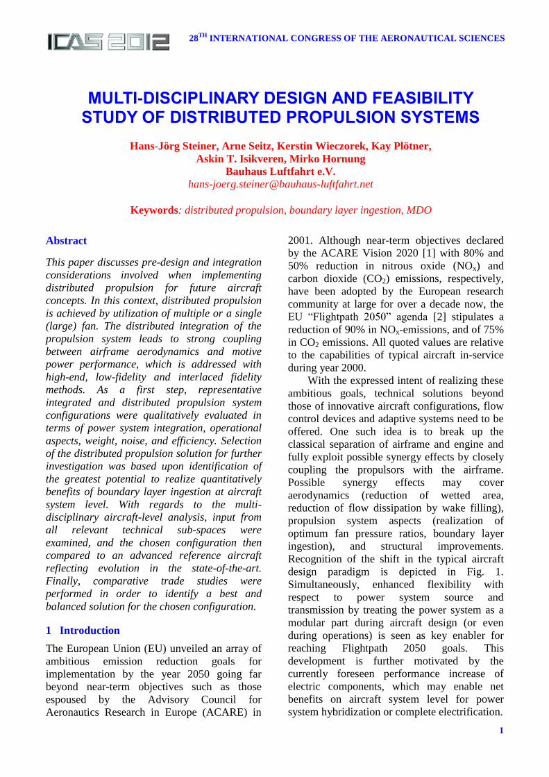
Recognition of the shift in the typical aircraft
design paradigm is depicted in Fig. 1.
Simultaneously, enhanced flexibility with
respect to power system source and
transmission by treating the power system as a
modular part during aircraft design (or even
during operations) is seen as key enabler for
reaching Flightpath 2050 goals. This
development is further motivated by the
currently foreseen performance increase of
electric components, which may enable net
benefits on aircraft system level for power
system hybridization or complete electrification.
MULTI-DISCIPLINARY DESIGN AND FEASIBILITY STUDY OF DISTRIBUTED PROPULSION SYSTEMS
Hans-Jörg Steiner, Arne Seitz, Kerstin Wieczorek, Kay Plötner,
Askin T. Isikveren, Mirko Hornung
Bauhaus Luftfahrt e.V.
Keywords: distributed propulsion, boundary layer ingestion, MDO
Hans-Jörg Steiner, Arne Seitz, Kerstin Wieczorek, Kay Plötner, Askin T. Isikveren, Mirko Hornung
2
Fig. 1. Shift in aircraft design paradigm moti-
vating integrated [distributed] propulsion.
1.1 Overview of Distributed Propulsion
The investigation of aircraft concepts with
distributed propulsion is gaining increased
attention. An overview of the different types of
distributed propulsion vehicles has been given
by Kim [3] using the following classification:
Jet flaps (blowing engine exhaust out of
the wing trailing edge) [4],[5]
Cross-flow fan (2D propulsor integrated
within the wing trailing edge) [6],[7]
Multiple discrete engines (driven by
their own power source) [8],[9],[10]
Distributed multi-fans driven by a
limited number of engine cores;
transmission approaches include
o Gas-driven (pneumatic)
o Gear-driven (mechanic)
o Electrically driven
Common to all of those concepts is the idea of
distributing the thrust-producing jet stream in
order to increase overall vehicle efficiency. In
the context of this paper, a new type of concept
will be added, which is justified by targeting the
same goal. This configuration is characterized
by a single-rotating or counter-rotating fan
encircling the fuselage with intent to entrain the
fuselage boundary layer and distribute the thrust
along the viscous wake generated by the
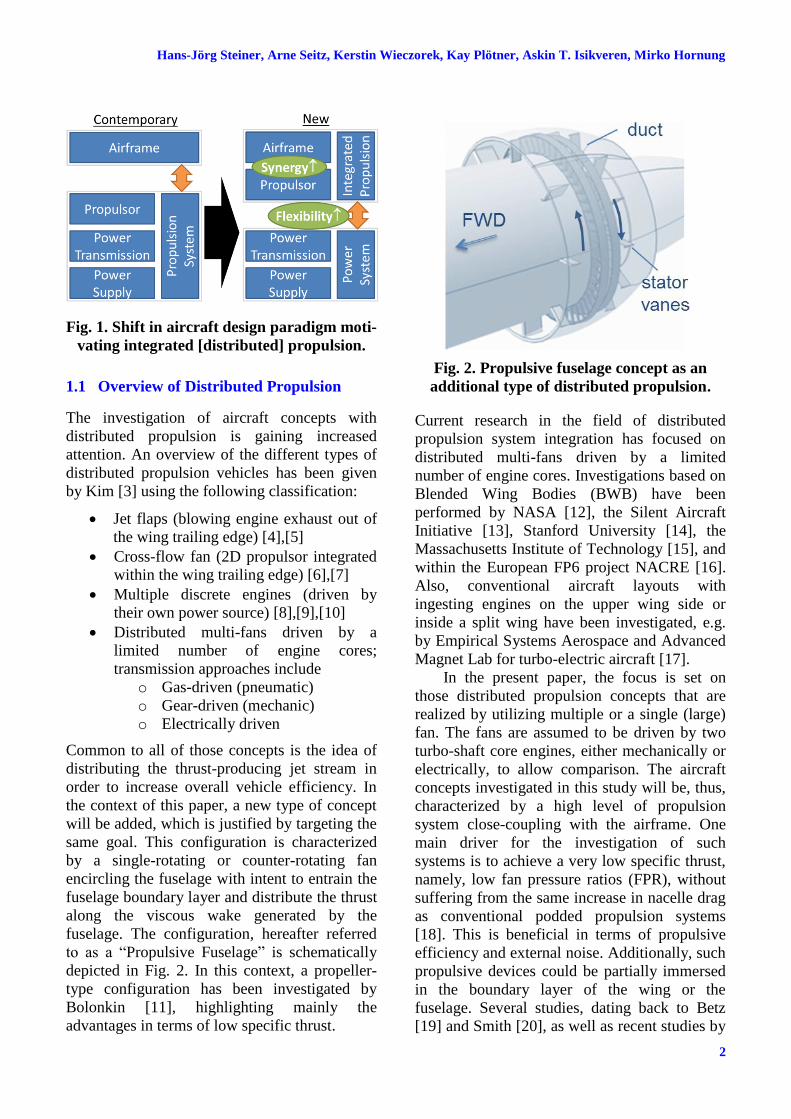
fuselage. The configuration, hereafter referred
to as a “Propulsive Fuselage” is schematically
depicted in Fig. 2. In this context, a propeller-
type configuration has been investigated by
Bolonkin [11], highlighting mainly the
advantages in terms of low specific thrust.
Fig. 2. Propulsive fuselage concept as an
additional type of distributed propulsion.
Current research in the field of distributed
propulsion system integration has focused on
distributed multi-fans driven by a limited
number of engine cores. Investigations based on
Blended Wing Bodies (BWB) have been
performed by NASA [12], the Silent Aircraft
Initiative [13], Stanford University [14], the
Massachusetts Institute of Technology [15], and
within the European FP6 project NACRE [16].
Also, conventional aircraft layouts with
ingesting engines on the upper wing side or
inside a split wing have been investigated, e.g.
by Empirical Systems Aerospace and Advanced
Magnet Lab for turbo-electric aircraft [17].
In the present paper, the focus is set on
those distributed propulsion concepts that are
realized by utilizing multiple or a single (large)
fan. The fans are assumed to be driven by two
turbo-shaft core engines, either mechanically or
electrically, to allow comparison. The aircraft
concepts investigated in this study will be, thus,
characterized by a high level of propulsion
system close-coupling with the airframe. One
main driver for the investigation of such
systems is to achieve a very low specific thrust,
namely, low fan pressure ratios (FPR), without
suffering from the same increase in nacelle drag
as conventional podded propulsion systems
[18]. This is beneficial in terms of propulsive
efficiency and external noise. Additionally, such
propulsive devices could be partially immersed
in the boundary layer of the wing or the
fuselage. Several studies, dating back to Betz
[19] and Smith [20], as well as recent studies by

3
MULTI-DISCIPLINARY DESIGN AND FEASIBILITY STUDY OF
DISTRIBUTED PROPULSION SYSTEMS
Felder [21], indicate an increase of propulsive
efficiency for propulsors utilizing boundary
layer ingestion (BLI). Also, recent
investigations conducted by Sato [15] seem to
confirm the benefit of BLI, which was found to
be primarily due to the reduction of jet and
wake dissipation, and increases with the amount
of boundary layer ingested into the propulsor.
This paper contributes to the research on
distributed propulsion aircraft by proposing
methods and models for estimating
aerodynamic, propulsive, and structural aspects
necessary for a pre-design, multi-disciplinary
assessment of integrated propulsion systems.
Notably, the study aims to investigate the
possible benefit of BLI at aircraft system level
by selecting a “best suited” aircraft
configuration for realizing BLI-borne benefits.
This configuration is to be subsequently
analyzed using higher order methods as part of
future research activities, and thus, may act as
an established upper bound case for BLI
applications.
1.2 Approach of this Study
The content of the presented paper is divided in
two main parts. The first part (Section 2)
presents the documentation of the down-
selection process, which has been carried out to
determine the best suited distributed propulsion
configuration for the specified requirements. It
has to be noted that the individual weighting of
these requirements reflects rather the scientific
goals of this study, as opposed to offering a
realistic economic evaluation. Preceding the
down-selection the basic principles of BLI are
described, which allow for an estimation of the
performance of distributed propulsion systems.
The second part (Section 3) consists of a multi-
disciplinary analysis of the selected propulsion
concept, showing the design trade-off between
the involved disciplines, and a comparison of
the design result against that of an advanced
reference aircraft.
2 Qualitative Concept Down-Selection
The following section describes the formal
down-selection process that was carried out in
order to identify the most promising concept,
i.e. one that can realize maximum efficiency
benefits associated with distributed propulsion.
The first two sub-sections are dedicated to the
estimation of the potential efficiency benefit
related to BLI, since this has been declared as
one of the main motivators for distributed
propulsion concepts. It is pointed out that using
the Power Saving Coefficient (PSC, as
introduced by Smith [20] in earlier work) as a
metric allows for a suitable quantification of
BLI benefits even at a pre-design stage. The
results are shown and discussed in Section 2.2.
2.1 Boundary Layer Ingestion - Overview
The potential for increasing the efficiency of an
integrated propulsion system by ingesting slow
boundary layer flow can be illustrated by the
application of basic zero-dimensional actuator
disk theory. Neglecting pressure contributions
(assuming a fully expanded nozzle), the ideal
propulsive efficiency p (ratio of usable power
TV compared to the kinetic power P added to
the flow) of a propulsor with inlet velocity V1,
outlet velocity V2, and flight (freestream)
velocity V∞ is given by
22
12
1
2
2
12
VV
V
VVm
VVVm
P
VTP
(1)
As Equation (1) indicates, possibilities to
enhance the propulsive efficiency are on the one
hand the reduction of specific thrust, i.e. the
reduction of V = V2 - V1, or a reduction of V1.
The first option implies an increase of mass
flow ̇ for a required thrust T and correlates to
an increase of bypass ratio for turbofan engines.
The second option equals a reduction in ram
drag as achieved through BLI.
A physical explanation for this efficiency
increase is given by the consideration of energy
losses in the flow field, as described by Drela
[22]. In general, propulsive efficiency loss is a
consequence of any net kinetic energy left in the
wake (characterized by non-uniformities in the
velocity profile) compared to that of a uniform
velocity profile [23]. These non-uniformities are
the reason for fluid friction, and hence, for
dissipation of energy in the trailing wake until
the velocity field is uniform again. These energy

Hans-Jörg Steiner, Arne Seitz, Kerstin Wieczorek, Kay Plötner, Askin T. Isikveren, Mirko Hornung
4
losses due to friction can be reduced by
designing an integrated propulsion system such
that velocity profile non-uniformities are
minimized by filling the wake. Fig. 3 illustrates
the basic principle of wake filling for different
levels of propulsion system integration.
Fig. 3. Illustration of the basic principle for
wake filling.
The classical case of separated body and engine
is shown in the upper most portion of Fig. 3. For
the simplification of a self-propelled case (no
additional drag components like induced drag or
wave drag) the momentum excess of the jet
must equal the momentum deficit in the wake
due to viscous body drag. The propulsive
efficiency of the overall system is improved if
the jet “fills in” the wake directly behind the
body. This is shown with the two cases for
integrated propulsion systems in the bottom
portion of Fig. 3. In the ideal system, the jet
perfectly fills in the wake, creating a uniform
velocity profile. In this case, there are no losses
due to dissipation occurring in the wake of the
integrated system. However, the jet does not
fully fill in the wake in practice, but rather
creates smaller non-uniformities in the velocity
profile, as illustrated in the middle part of Fig.
3. The resulting velocity profile contains a
smaller net kinetic energy than that of the case
where the body and engine are independent.
However, for any closely coupled propulsion
system it may become necessary to assess the
overall system efficiency by evaluating the
losses in the complete flowfield.
2.2 Boundary Layer Ingestion - Methods
A first detailed quantification of the concept of
wake ingestion was investigated by Smith [20].
He applied an incompressible actuator disk
model and described the wake by integral wake
properties like wake displacement area. These
wake parameters together with the ratio of
ingested drag to total thrust can be used to
calculate the propulsive efficiency and a PSC
indicating the wake ingestion benefit. The PSC
used in the following is defined as the reduction
in power due to BLI relative to the total power
requirement without BLI, viz.
NoBLI
BLINoBLI
P
PPPSC
(2)
The analysis of Smith shows that the main
impact on PSC correlates well with the ratio of
ingested drag to total thrust, Ding/T. The Ding
parameter “Ingested drag” in this context
describes the amount of viscous drag generated
on that part of the airframe surface, which is
wetted by the flow entering the propulsive
device.
The following down-selection takes
advantage of the fact that this property can be
easily estimated for a given aircraft
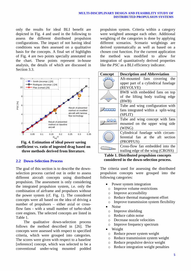
configuration. The PSC derived by Smith [20] is
depicted in Fig. 4 assuming typical values of a
turbulent boundary layer profile, a wake
recovery factor of R = 0.90 (this describes the
capability of the propulsor to flatten the wake),
and a thrust coefficient of CT = 0.70, which is a
reasonable value for an integrated propulsion
system and corresponds to a FPR = 1.35 at
typical cruise conditions. CT is defined as the
specific thrust per propulsor area AP, normalized
by freestream dynamic pressure q∞:
qA
TC
P
T
(3)
Additionally, Fig. 4 shows results derived by
Rodriguez [24] and Plas [25] that confirm the
achievable ideal benefit determined by Smith
[20]. Plas used a compressible parallel
compressor model with FPR = 1.50. Even if he
also calculated PSC values for non-ideal
conditions (non-ideal fan, distortion transfer),
5
MULTI-DISCIPLINARY DESIGN AND FEASIBILITY STUDY OF
DISTRIBUTED PROPULSION SYSTEMS
only the results for ideal BLI benefit are
depicted in Fig. 4 and used in the following to
assess the different distributed propulsion
configurations. The impact of not having ideal
conditions was then assessed on a qualitative
basis for the concepts. A final set of highlights
of Fig. 4 are two points specially annotated on
the chart. These points represent in-house
analysis, the details of which are discussed in
Section 3.3.
Fig. 4. Estimation of ideal power saving
coefficient vs. ratio of ingested drag based on
three methods derived from literature.
2.2 Down-Selection Process
The goal of this section is to describe the down-
selection process carried out in order to assess
different aircraft concepts using distributed
propulsion. The assessment is only considering
the integrated propulsion system, i.e. only the
combination of airframe and propulsors without
the power system (cf. Fig. 1). The considered
concepts were all based on the idea of driving a
number of propulsors – either axial or cross-
flow fans - with a small number of turbo-shaft
core engines. The selected concepts are listed in
Table 1.
The qualitative down-selection process
follows the method described in [26]. The
concepts were assessed with respect to specified
criteria, which were grouped into categories.
The scores were given with respect to a baseline
[reference] concept, which was selected to be a
conventional under-wing mounted podded
propulsion system. Criteria within a category
were weighted amongst each other. Additional
weighting of the categories is done by applying
different scenarios. Scenario weightings are
derived systematically as well as based on a
chosen cost function. For the current application
the method was modified to allow for
integration of quantitatively derived properties
like the PSC as a BLI efficiency indicator.
Concept Description and Abbreviation
Aft-mounted fans covering the
upper part of a cylindrical fuselage
(REVOLVE)
BWB with embedded fans on top
of the lifting body trailing edge
(BWB)
Tube and wing configuration with
fans integrated within a split-wing
(SPLIT)
Tube and wing concept with fans
mounted on the upper wing side
(WING)
Cylindrical fuselage with circum-
ferential fan at the aft section
(PROPFUS)
Cross-flow fan embedded into the
trailing edge of the wing (CROSS)
Table 1. Distributed propulsion concepts
considered in the down-selection process.
The criteria used for assessing the distributed
propulsion concepts were grouped into the
following categories:
Power system integration
o Improve volume restrictions
o Improve accessibility
o Reduce thermal management effort
o Improve transmission system flexibility
Noise
o Improve shielding
o Reduce cabin noise
o Decrease nozzle velocities
o Improve frequency spectrum
Weight
o Reduce power system weight
o Reduce transmission system weight
o Reduce propulsive device weight
o Reduce integration weight penalties
0 0.05 0.1 0.15 0.2 0.25 0.3 0.350
2
4
6
8
10
12
Ding
/T
PS
C [
%]
Smith (incompr.) [20]
Rodriguez (incompr.) [24]
Plas (compr) [25]
Result of presented
method on baseline
aircraft
Result of presented
method on modified
aircraft with laminar
flow technology
Hans-Jörg Steiner, Arne Seitz, Kerstin Wieczorek, Kay Plötner, Askin T. Isikveren, Mirko Hornung
6
Operability (technical)
o Relax geometric constraints
o Improve controllability
o Improve operational robustness
o Improve robustness against Foreign-
Object-Damage
o Reduce impact of propulsor failure
Operability (non-technical)
o Improve passenger attractiveness
o Improve ramp safety
o Improve loadability
o Augment high-lift
o Improve maintenance
Efficiency potential
o Maximize feasible intake area
o Improve efficiency due to BLI (PSC)
o Reduce integration drag
o Improve propulsor pressure recovery
o Reduce propulsor inflow distortion
All criteria except the BLI benefit were
qualitatively assessed with respect to the
baseline configuration using scores out of -3, -1,
0 [parity with baseline], +1, and +3. The BLI
benefit potential was estimated using the PSC as
described in the next section.
2.3 Estimation of the BLI potential
The potential of the selected concepts to achieve
an efficiency increase due to BLI was estimated
based on Fig. 4 yielding the ideal PSC. The ratio
of Ding/T was estimated with the following
equation
D
D
D
ingD
D
ingDing
C
C
C
C
C
C
T
D0
0
,0,0
(4)
Minimum and maximum values for the
proportion of viscous drag that is ingested by
the propulsor are determined based on
geometric considerations for each of the
concepts depicted in Table 1. The ratio of
viscous drag to total drag CD0/CD was assumed
to be 55-65% for all concepts in order to reflect
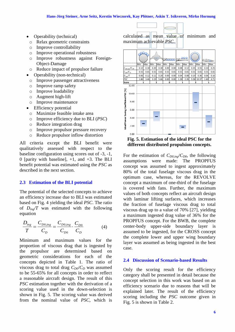
a reasonable aircraft design. The result of this
PSC estimation together with the derivation of a
scoring value used in the down-selection is
shown in Fig. 5. The scoring value was derived
from the nominal value of PSC, which is
calculated as mean value of minimum and
maximum achievable PSC.
Fig. 5. Estimation of the ideal PSC for the
different distributed propulsion concepts.
For the estimation of CD0,ing/CD0, the following
assumptions were made: The PROPFUS
concept was assumed to ingest approximately
80% of the total fuselage viscous drag in the
optimum case, whereas, for the REVOLVE
concept a maximum of one-third of the fuselage
is covered with fans. Further, the maximum
values of both concepts reflect an aircraft design
with laminar lifting surfaces, which increases
the fraction of fuselage viscous drag to total
viscous drag up to a value of 70% [27], yielding
a maximum ingested drag value of 36% for the
PROPFUS concept. For the BWB, the complete
center-body upper-side boundary layer is
assumed to be ingested, for the CROSS concept
the complete lower and upper wing boundary
layer was assumed as being ingested in the best
case.
2.4 Discussion of Scenario-based Results
Only the scoring result for the efficiency
category shall be presented in detail because the
concept selection in this work was based on an
efficiency scenario due to reasons that will be
explained later. The result of the efficiency
scoring including the PSC outcome given in
Fig. 5 is shown in Table 2.
Min Max Min Max Min Max Min Max Min Max Min Max
C D0,ing /C D0 0.12 0.18 0.20 0.30 0.00 0.00 0.08 0.12 0.35 0.55 0.10 0.25
C D0 /C D 0.55 0.65 0.55 0.65 0.55 0.65 0.55 0.65 0.55 0.65 0.55 0.65
D ing /T 0.06 0.12 0.11 0.20 0.00 0.00 0.04 0.08 0.19 0.36 0.06 0.16
PSC 1.86 3.46 3.19 5.66 0.00 0.00 1.28 2.26 5.58 10.37 1.60 4.71
Score 3 11 2 0 1
Airframe
Propulsor
Power Supply
Power Transmission
Pro
pu
lsio
n
Syst
em
Airframe
Propulsor
Power Supply
Power Transmission
Po
we
rSy
ste
mIn
tegr
ate
d
Pro
pu
lsio
n
Synergy
Flexibility

7
MULTI-DISCIPLINARY DESIGN AND FEASIBILITY STUDY OF
DISTRIBUTED PROPULSION SYSTEMS
Table 2. Scores of the category “Efficiency”.
The first criterion reflects the possibility to shift
the optimum value of the propulsor area to
higher values by embedding the propulsors
within the airframe, thereby reducing the
specific thrust and increasing ηP [28]. The BLI
efficiency was scored based on the PSC analysis
discussed before. The possible reduction of
integration drag includes nacelle drag as well as
interference drag. Propulsor pressure recovery
has a major impact on the efficiency of the
integrated propulsion system. A degradation of
pressure recovery is expected for all integrated
propulsion concepts due to necessary ducting
and mixing. Also the increased inflow distortion
compared to the podded reference case has to be
accounted for when assessing a concept.
The scoring and weighting as shown in
Table 2 resulted in the PROPFUS being
assessed as the most promising concept from an
efficiency point of view due to the significant
BLI benefit, combined with low losses due to
pressure recovery and inflow distortion. The
BWB ranked second due to lower PSC and
higher losses accompanied with BLI.
REVOLVE and CROSS concepts are third due
to lower PSC potential.
The final result of the down-selection using
a normalized score and applying different
weighting scenarios is given in Fig. 6. The score
of the reference case (2 podded wing-mounted
engines) is 0.50 for all scenarios and not shown
in the figure. The first scenario reflects a cost
oriented scenario which aims at assessing the
concepts with respect to operating costs. In this
scenario the BWB yields the best result,
followed by the PROPFUS and the REVOLVE
concepts. The remaining scenarios are defined
by a systematic variation of the category
weights, such that one category is weighted with
0.50 and the remaining weights are equally
distributed amongst the other categories. From
this analysis it can be deduced that the
PROPFUS concept is scoring best from an
efficiency perspective. However, the concept is
also showing a very high deviation amongst the
different scenarios with less good scoring of the
operational scenarios (including geometric
constraints for tail-strike, high impact of
propulsor failure, and Foreign Object Damage
due to icing and debris).
Nonetheless, it was decided to further
investigate the PROPFUS concept with the
intention of quantitatively assessing the possible
benefit of BLI at aircraft system level for an
aircraft configuration that features the highest
Efficiency Potential Ref
REV
OLV
EBW
B
SPLI
T
WIN
G
PRO
PFU
SCR
OSS
Weight
Maximize feasible intake area 0 3 3 0 0 3 1 0.30
Improve BLI Efficiency (PSC) 0 1 2 0 1 3 1 0.35
Reduce integration drag 0 0 0 -1 -3 1 1 0.10
Improve propulsor pressure recovery 0 -3 -3 0 -1 -1 -1 0.20
Reduce propulsor inflow distortion 0 -3 -3 0 -3 -1 -1 0.05
Score 0.00 0.50 0.85 -0.10 -0.30 1.80 0.50
Normalized Score 0.50 0.58 0.64 0.48 0.45 0.80 0.58
Fig. 6. Results of the down-selection of distributed propulsion concepts. Shown are normalized
scores for different scenarios (score of the podded reference concept is 0.50).

Hans-Jörg Steiner, Arne Seitz, Kerstin Wieczorek, Kay Plötner, Askin T. Isikveren, Mirko Hornung
8
potential to realize the BLI benefit. The
identified issues with respect to the chosen
PROPFUS concept emphasizes the need for
delivering amenable engineering solutions
during detailed integration and sizing activities
(to be conducted at a later stage).
3 Propulsive Fuselage Design Study
The Propulsive Fuselage concept consists of a
single-rotating or counter-rotating ducted fan
encircling the rear part of a cylindrical fuselage
section (cf. Fig. 2). A large share of the fuselage
boundary layer flow can be ingested into the
propulsor without encountering severe
circumferential flow distortion. The share of
BLI depends on the position of the propulsor
relative to the fuselage length.
The goal of this pre-design study was to set
up a multi-disciplinary model allowing for a
first estimate of the potential benefit compared
to a reference podded configuration. This
involved the execution of sensitivity analyses
with purpose to quantify the influence of main
aircraft and propulsion system design
parameters, such as fuselage type (narrow-body,
wide-body, short wide-body) and FPR, on the
achievable benefit to vehicular efficiency.
3.1 Estimation of Propulsor Efficiency and
Power Saving Coefficient
A zero-dimensional performance model of a
ducted fan with the ability to predict design and
off-design performance was created in order to
estimate the propulsive device efficiency Prop.
Propulsive device efficiency is defined as the
ratio of usable propulsion power (net thrust
times flight speed, TV∞) to fan shaft power,
hence covering propulsive efficiency p, fan
polytropic efficiency, as well as intake, ducting
and nozzle losses. The model is based on basic
gas-dynamic relationships and standard
compressor theory [29]. The fan model is
coupled with a numerically achieved boundary
layer representation to estimate the BLI benefit
by applying a simple equivalent intake velocity
model.
The equivalent mean velocity as well as the
equivalent total pressure at the propulsor intake
is derived from the local boundary layer
properties, which are measured from numerical
CFD simulations performed for the clean
fuselage [30]. The equivalent value is dependent
upon the height of the propulsor intake, h, and is
calculated as a mass flow averaged mean value.
In Fig. 7 the equivalent velocity is shown
for three different investigated fuselage types:
typical narrow-body (L = 43.0 m, D = 4.00 m);
typical wide-body (L = 56.0 m, D = 5.50 m);
and, a short wide-body (L = 43.0 m, D = 5.50
m). In all cases the propulsor intake is located at
75% of the fuselage length, representative of the
point at which the constant cross-section due to
cabin requirements terminates.
Fig. 7. Equivalent velocity as a function of
propulsor intake height for three different
fuselage types (numerical CFD results [30]).
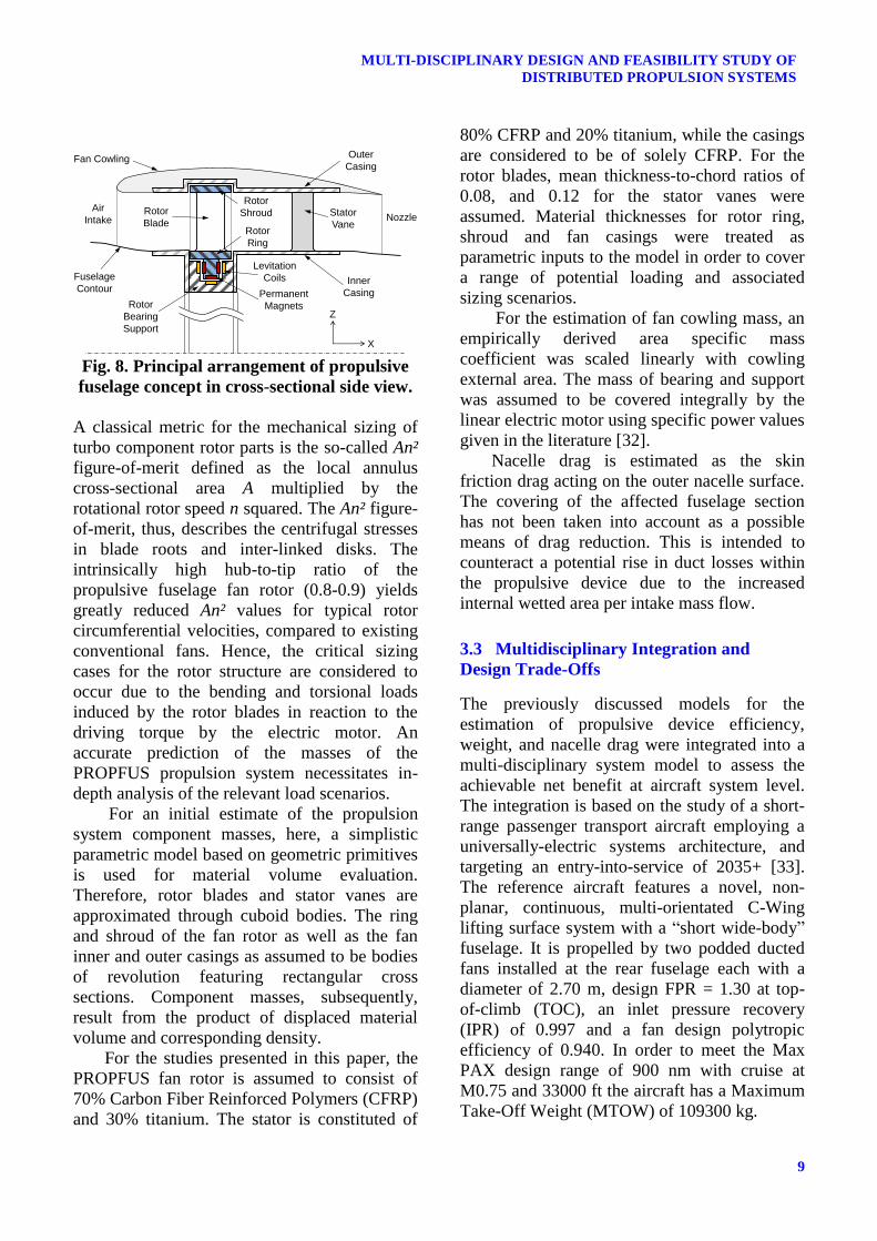
3.2 Estimation of Weight and Drag
In Fig. 8, a simplified cross-sectional side view
of a possible integrated propulsive fuselage
concept is shown. The fan rotor is considered to
be a shrouded BLaded rING (BLING), powered
by a quasi-linear electric motor arrangement
analogous to the design described in Reference
[31]. The electromagnetic fields induced by the
indicated levitation coils offer a convenient
rotor bearing solution since friction losses can
be minimized. It should be noted that the
feasibility of the rotor BLING as a single piece
design requires a more detailed evaluation in
terms of manufacturing, maintenance as well as
assembly and disassembly procedures.
0.5 0.55 0.6 0.65 0.7 0.75 0.8 0.85 0.9 0.95 10
0.2
0.4
0.6
0.8
1
1.2
1.4
1.6
1.8
2In
take H
eig
ht
h [
m]
Equivalent velocity V/V0
Narrow-Body (75%)
Wide-Body (75%)
Short Wide-Body (75%)
9
MULTI-DISCIPLINARY DESIGN AND FEASIBILITY STUDY OF
DISTRIBUTED PROPULSION SYSTEMS
Fig. 8. Principal arrangement of propulsive
fuselage concept in cross-sectional side view.
A classical metric for the mechanical sizing of
turbo component rotor parts is the so-called An²
figure-of-merit defined as the local annulus
cross-sectional area A multiplied by the
rotational rotor speed n squared. The An² figure-
of-merit, thus, describes the centrifugal stresses
in blade roots and inter-linked disks. The
intrinsically high hub-to-tip ratio of the
propulsive fuselage fan rotor (0.8-0.9) yields
greatly reduced An² values for typical rotor
circumferential velocities, compared to existing
conventional fans. Hence, the critical sizing
cases for the rotor structure are considered to
occur due to the bending and torsional loads
induced by the rotor blades in reaction to the
driving torque by the electric motor. An
accurate prediction of the masses of the
PROPFUS propulsion system necessitates in-
depth analysis of the relevant load scenarios.
For an initial estimate of the propulsion
system component masses, here, a simplistic
parametric model based on geometric primitives
is used for material volume evaluation.
Therefore, rotor blades and stator vanes are
approximated through cuboid bodies. The ring
and shroud of the fan rotor as well as the fan
inner and outer casings as assumed to be bodies
of revolution featuring rectangular cross
sections. Component masses, subsequently,
result from the product of displaced material
volume and corresponding density.
For the studies presented in this paper, the
PROPFUS fan rotor is assumed to consist of
70% Carbon Fiber Reinforced Polymers (CFRP)
and 30% titanium. The stator is constituted of
80% CFRP and 20% titanium, while the casings
are considered to be of solely CFRP. For the
rotor blades, mean thickness-to-chord ratios of
0.08, and 0.12 for the stator vanes were
assumed. Material thicknesses for rotor ring,
shroud and fan casings were treated as
parametric inputs to the model in order to cover
a range of potential loading and associated
sizing scenarios.
For the estimation of fan cowling mass, an
empirically derived area specific mass
coefficient was scaled linearly with cowling
external area. The mass of bearing and support
was assumed to be covered integrally by the
linear electric motor using specific power values
given in the literature [32].
Nacelle drag is estimated as the skin
friction drag acting on the outer nacelle surface.
The covering of the affected fuselage section
has not been taken into account as a possible
means of drag reduction. This is intended to
counteract a potential rise in duct losses within
the propulsive device due to the increased
internal wetted area per intake mass flow.
3.3 Multidisciplinary Integration and
Design Trade-Offs
The previously discussed models for the
estimation of propulsive device efficiency,
weight, and nacelle drag were integrated into a
multi-disciplinary system model to assess the
achievable net benefit at aircraft system level.
The integration is based on the study of a short-
range passenger transport aircraft employing a
universally-electric systems architecture, and
targeting an entry-into-service of 2035+ [33].
The reference aircraft features a novel, non-
planar, continuous, multi-orientated C-Wing
lifting surface system with a “short wide-body”
fuselage. It is propelled by two podded ducted
fans installed at the rear fuselage each with a
diameter of 2.70 m, design FPR = 1.30 at top-
of-climb (TOC), an inlet pressure recovery
(IPR) of 0.997 and a fan design polytropic
efficiency of 0.940. In order to meet the Max
PAX design range of 900 nm with cruise at
M0.75 and 33000 ft the aircraft has a Maximum
Take-Off Weight (MTOW) of 109300 kg.
Fuselage
Contour
Fan Cowling
Stator
Vane
Inner
Casing
Outer
Casing
Rotor
Bearing
Support
Levitation
Coils
Permanent
Magnets
Air
Intake Nozzle
Rotor
Shroud
X
Z
Rotor
BladeRotor
Ring

Hans-Jörg Steiner, Arne Seitz, Kerstin Wieczorek, Kay Plötner, Askin T. Isikveren, Mirko Hornung
10
Prior to showing the integrated results, a
discussion of the isolated propulsor
characteristics is worthwhile. The propulsor
device efficiency ηProp as a function of design
FPR and IPR is shown in Fig. 9.
Fig. 9. Propulsor device efficiency vs design
FPR for different IPR (no BLI, 17% and
30% ingested drag ratio).
The depicted design point in Fig. 9 shows that
the podded fans of the reference aircraft without
BLI are designed for a higher FPR than the
optimum due to the counteracting influence of
propulsor weight and drag at aircraft level. The
efficiency for the BLI case is shown for Ding/T
ratios of 17% and 30%. For a baseline
PROPFUS configuration directly derived from
the reference aircraft by replacing the
propulsion system (with a relative propulsor
position at 75% fuselage length) a Ding/T = 17%
was calculated, yielding an increase of 1.6% in
ηProp. Here, an IPR = 0.990 was assumed for the
BLI case, i.e. three times higher intake pressure
loss compared to the podded reference case. The
low Ding/T for this aircraft is due to a high wing
loading (leading to a high induced drag ratio)
and a low fuselage viscous drag fraction due to
the complex wing system with high sweep angle
featuring no laminar flow. However, for an
aircraft design with laminar wing technology
and lower wing loading, an ingested drag ratio
of 30% could be achieved (based on [27]),
increasing the possible ηProp benefit to 5.2%.
The corresponding PSC values of the results
achieved with the presented method are plotted
in Fig. 4 for comparison with existing methods
(using a constant FPR of 1.35). It can be seen
that the results agree with literature with a
gradually widening extent of under-prediction
for higher Ding/T.
Referring again to Fig. 9, it should also be
noted that the optimum FPR for the BLI case
shifts to higher values and exhibits a lower
slope towards higher FPR. This results from the
beneficial reduction of propulsor inlet velocity
if the propulsor height is reduced, and hence,
the boundary layer constitutes a larger fraction
of the inflow (cf. Fig. 7). In addition, the
expected larger inlet pressure losses for BLI
shift the optimum to higher FPR.
The net benefit at aircraft system level is
predicted using a linearized equation for the
design range R derived from the reference
aircraft at constant MTOW, viz.
NacD
NacD
Prop
Prop
Prop
Prop
SCSC
R
Rm
m
RRR
0
(5)
where R0 is the reference aircraft range, mProp is
the propulsor device mass, “Nac” denotes
nacelle, and S is the reference wing area. If this
is normalized by the total mission energy
demand E, which is derived accordingly, a
figure-of-merit referred to as the energy specific
air range R/E can be estimated. The possible
relative increase of R/E is shown in Fig. 10.
Fig. 10. Energy specific air range increase as
a function of design FPR and IPR.

11
MULTI-DISCIPLINARY DESIGN AND FEASIBILITY STUDY OF
DISTRIBUTED PROPULSION SYSTEMS
It can be seen that the derived optimum FPR
values at aircraft level are considerably higher
than for the non-BLI case. With Ding/T = 17% a
FPR of 1.4 yields the most efficient design with
a 3.1% benefit over the reference [non-BLI]
configuration. Assuming Ding/T = 30%, an
improvement over the baseline of up to 9.4%
was predicted. Here, nominal values for the
weight estimation model were assumed.
The calculated relative increase in range
compared to the reference aircraft is shown in
Fig. 11. In order to maximize range, the analysis
indicates higher FPRs in the range of 1.45-1.50
are necessary. This is due to the direct impact of
weight on the available battery mass for the
specified condition of constant MTOW. Aircraft
range can be increased by 2.9% assuming a
Ding/T of 17%. If design modifications can be
implemented for an optimized aircraft design
with Ding/T = 30% a possible relative range
increase of up to 10.6% is predicted.
Fig. 11. Range increase as a function of
design FPR and IPR.
4 Summary and Outlook
The purpose of this technical paper was to
investigate the merits of distributed propulsion
for future aircraft concepts. Initially, from a
pool of five different integration approaches,
whether involving single or multiple rotating
fans, a relatively comprehensive qualitative
evaluation was performed in order to down-
select the best candidate. Categories included
power system integration, operational aspects,
weight, noise and efficiency. The greatest
weighting in the selection procedure was
assigned to a quantitatively analyzed category
that addressed greatest potential to realize the
benefits of boundary layer ingestion (BLI). The
exercise showed that although the so-called
“Propulsive Fuselage” did exhibit shortcomings
regarding a number of operational attributes, the
significant potential for efficiency gains
compared to the other candidates was the
deciding factor in its choice. Utilizing a set of
high-end, low-fidelity and interlaced fidelity
numerical tools a series of engineering trade-
studies took place in order to identify an upper
limit of vehicle efficiency and range
improvement compared to an advanced
reference passenger transport aircraft not
employing BLI. One major finding of this study
was that BLI is able to increase aircraft
efficiency not just simply by increasing the
propulsive efficiency of the fans, but also by
shifting the optimum fan pressure ratio to higher
values, hence allowing for a smaller propulsor
size, and thus, lower weight and drag of the
propulsion system. Results showed that
integration emphasizing a BLI-focused
approach could yield as much as 10.6%
improvement in range. Less emphasis on a BLI-
centric design philosophy produced a range
improvement of 2.9%. Looking ahead, based
upon the pre-design work discussed above, next
steps will involve design and integration at a
more detailed level. The implementation of an
advanced toolset will be done in order to
capture functional sensitivities between primary
design variables associated with closely coupled
systems found in the Propulsive Fuselage.
References
[1] Advisory Council for Aeronautical Research in
Europe (ACARE). European aeronautics: A vision
for 2020. January 2001.
[2] European Commission (EC). Flightpath 2050:
Europe’s vision for aviation, report of the high level
group on aviation research. Publications Office of
the European Union, Luxembourg, 2011.
[3] Kim H D. Distributed propulsion vehicles. 27th
International Congress of the Aeronautical Sciences,
Nice, 2010.
[4] Schetz J A, Hosder S, et al. Propulsion and
aerodynamic performance evaluation of jet-wing
distributed propulsion. Aerospace Science and
Technology, Vol. 14, pp. 1-10, 2010.
Hans-Jörg Steiner, Arne Seitz, Kerstin Wieczorek, Kay Plötner, Askin T. Isikveren, Mirko Hornung
12
[5] Ko A, Leifsson L T, Schetz J A, Mason W H and
Grossman B. MDO of a blended-wing-body transport
aircraft with distributed propulsion. AIAA’s 3rd
Annual Aviation Technology, Integration, and
Operations (ATIO) Technical Forum, Denver, 2003.
[6] Dang T and Bushnell P. Aerodynamics of cross-flow
fans and their application to aircraft propulsion and
flow control. Progress in Aerospace Sciences, Vol.
45, Issues 1-3, pp 1-29, 2009.
[7] Gologan C, Mores S, Steiner H-J, and Seitz A.
Potential of the cross-flow fan for powered-lift
regional aircraft applications. 9th AIAA Aviation
Technology, Integration, and Operations Conference
(ATIO), 2009.
[8] Ameyugo G, Taylor M and Singh R. Distributed
propulsion feasibility studies. 25th International
Congress of the Aeronautical Sciences, 2006.
[9] Kim H D, Berton J J and Jones S M. Low noise
cruise efficient short take-off and landing transport
vehicle study. AIAA-2006-7738, 2006.
[10] Kok H J M. Quantitative assessment of a distributed
propulsion system featuring boundary layer ingestion
turbofan engines applied to a blended wing body
aircraft. Master Thesis, Delft University of
Technology, 2008.
[11] Bolonkin A. A high efficiency fuselage propeller
(“Fusefan”) for subsonic aircraft. World Aviation
Conference, San Francisco, 1999.
[12] Felder J L, Kim H D and Brown G V. Turboelectric
distributed propulsion engine cycle analysis for
hybrid-wing-body aircraft. 47th AIAA Aerospace
Sciences Meeting Including The New Horizons
Forum and Aerospace Exposition, Orlando, 2009.
[13] Hall C A. Low noise engine design for the silent
aircraft initiative. The Aeronautical Journal, Vol.
113, No. 1147, pp 599-607, 2009.
[14] Rodriguez D L, Multidisciplinary optimization
method for designing boundary-layer-ingesting inlets.
Journal of Aircraft, Vol. 46, pp 883-894, 2009.
[15] Sato S, Mody P C, Hall D K, Blanco E R, and
Hileman J I. Assessment of propulsion system
configuration and fuel composition on hybrid wing
body fuel efficiency. 49th AIAA Aerospace Sciences
Meeting, Orlando, 2011.
[16] Godard J L. Semi-buried engine installation: The
NACRE project experience. 27th International
Congress of the Aeronautical Sciences (ICAS), 2010.
[17] Gibson A R, Hall D, et al. The potential and
challenge of turboelectric propulsion for subsonic
transport aircraft. 48th AIAA Aerospace Sciences
Meeting, Orlando, Florida, 2010.
[18] Hall C A and Crichton D, Engine and installation
configurations for a silent aircraft. 17th International
Symposium on Airbreathing Engines, Munich, 2005.
[19] Betz A. Introduction to the theory of flow machines.
Pergamon Press, New York, 1966.
[20] Smith Jr. L H. Wake ingestion propulsion benefit.
Journal of Propulsion and Power, Vol. 9, pp 74-82,
1993.
[21] Felder J L, Kim H D and Brown G V. An
examination of the effect of boundary layer ingestion
on turboelectric distributed propulsion systems. 49th
AIAA Aerospace Sciences Meeting, Orlando, 2011.
[22] Drela M. Power balance in aerodynamic flows. AIAA
Journal, Vol. 47, Issue 7, pp 1761-1771, 2009.
[23] Schetz J A, Hosder S, et al. Propulsion and
aerodynamic performance evaluation of jet-wing
distributed propulsion. Aerospace Science and
Technology, Vol. 14, No. 1, pp 1-10, 2010.
[24] Rodriguez D L. A multidisciplinary optimization
method for designing boundary layer ingesting inlets.
Dissertation, Stanford University, 2001.
[25] Plas A. Performance of a boundary layer ingesting
propulsion system. Master Thesis, Massachusetts
Institute of Technology, 2006.
[26] Mistree F, Lewis K, Stonis L. Selection in the
conceptual design of aircraft, AIAA 94-8342, 1994.
[27] Quast A and Horstmann K H. Profilauslegung für
Tragflügel und Propeller. Problems and Development
Trends in General Aviation, Symposium,
Friedrichshafen, March 24-25, 1983.
[28] Hall, C A and Crichton D. Engine and installation
configurations for a silent aircraft. 17th International
Symposium on Airbreathing Engines, 2005.
[29] Steiner H-J, Schmitz O. Ducted fan model. Internal
Report IB-11013, Bauhaus Luftfahrt e.V., 2011.
[30] Van Dyck L. Design study of a boundary layer
ingesting Propulsive Fuselage concept. Master
Thesis, Delft University of Technology, 2012.
[31] Eichenberg D J, Gallo C A, Solano P A, Thompson
W K, and Vrnak D R. Development of a 32 inch
diameter levitated ducted fan conceptual design.
NASA/TM—2006-214481, Glenn Research Center,
Cleveland, Ohio, 2006.
[32] Masson P J, Nam T, at al. Superconducting ducted
fan design for reduced emissions aeropropulsion.
IEEE Transactions on Applied Superconductivity,
Vol. 19, No. 3, pp. 1662-1668, 2009.
[33] Visionary Aircraft Concepts Group. Concept 002:
Initial technical assessment of an electrically-
powered, medium-capacity, short-haul transport
aircraft, Internal Report IB-12021, Bauhaus Luftfahrt
e.V., 2012.
Copyright Statement
The authors confirm that they, and/or their company or
organization, hold copyright on all of the original material
included in this paper. The authors also confirm that they
have obtained permission, from the copyright holder of
any third party material included in this paper, to publish
it as part of their paper. The authors confirm that they
give permission, or have obtained permission from the
copyright holder of this paper, for the publication and
distribution of this paper as part of the ICAS2012
proceedings or as individual off-prints from the
proceedings.